advantages of rafpentafloor.co.za/downloads/advantages of raf.pdf · · 2012-10-22to show the...
TRANSCRIPT

The advantages of raised access flooring 1
Note to the reader: The below is NOT a unique work or study, but rather an informative compilation of various studies done around the world to show the advantages of using a raised access floor from concetion phase right through to the recycling of the product after its lifespan as well as the duration in between. _________________________________________________________________________________________________________ The advantages of raised access flooring The use of access floors in the workplace is rapidly gaining popularity since they present a solution that is specifically designed to support information-rich and highly computerised business environments. Owners and developers, along with building designers and facility managers, face the challenges of constantly changing space needs, technology-driven operations, high churn rates and the almost impossible task of maintaining flexibility while keeping life-cycle costs down. All of these challenges demand a new outlook on planning and constructing buildings and some insight into assuring that all building systems are integrated so they become mutually supporting. The costs of both change and maintenance are exceptionally high in traditionally planned buildings, and in many instances users defer needed changes at the cost of organisational comfort and efficiency. In fact, many traditionally designed facilities become obsolete due to wiring and wiring distribution problems created by organisational changes and advances in technology. If the building is planned correctly though, with enough thought and creativity, changes can become almost routine and technology can be easily integrated. A well-designed, intelligent building not only has the flexibility and the capacity to accommodate change, it actually promotes change. The concept behind access floors An access floor is a floor placed upon a floor, thus creating an accessible plenum for the distribution of building services such as power, voice and data and the distribution of heating and cooling services. The floor can be raised by as little at 65 mm to more than 1,8 metres. The system is modular with the ability to plug and unplug any of the electrical components in the entire system from the panel board to the receptacle. The finished floor surface can be carpet tile, vinyl tile, laminate, finished concrete or natural materials such as wood or cork. The underfloor HVAC system not only eliminates most of the ductwork and insulation requirements associated with the overhead systems, but also enhances mechanical system flexibility because the non-ducted diffusers can be easily removed and relocated. Floor-mounted diffusers or workstation-mounted solutions distribute conditioned air from the access floor directly to the occupant’s level. From there the air gently mixes with the room air and rises to return grilles at ceiling level. The integrated access floor system also boosts the flexibility of telecommunications, data and electrical power delivery in the workstation. Simply by removing the access floor panels, building managers can now accommodate space and workstation changes as people relocate into, out of and around the office space. Benefits of access floors Integrated access floors for telecommunication, power and air distribution offer several economic and environmental benefits. Ease of reconfiguration, and easy access The integrated access floor system is engineered to permit fast, easy installation and quick wire and cable changes, enhancing the ability to reconfigure the offices without disrupting power, voice and data services, as well as the air distribution system.
The advantages of raised access flooring 2
Variable Air Volume (VAV) Terminals can be easily added, removed or rearranged to respond to changes in occupancy or heating and cooling loads. Even in workplaces with very low churn rates, constantly evolving technologies in the communications and networking sectors may demand occasional updating of the cabling and wiring systems. These updates are quite simple with access floors. Energy savings The use of an access floor plenum for conditional air distribution can significantly reduce energy use in many possible ways, such as a reduced fan power requirement. The underfloor supply plenum with the large cross-sectional flow areas can supply air with very low overall pressure drops. It also provides higher chiller efficiency. Underfloor systems can use warmer supply air, which permits a warmer cooling coil and warmer evaporator temperature in dry climates. In mild climates, the use of warmer supply air significantly expands the opportunity to use free cooling or the direct use of outside air, without operating a chiller. Also, since the airflow is from floor to ceiling, most of the heat generated from ceiling-mounted lights is removed before it can enter the occupied zone. The cooling load is therefore reduced, allowing warmer air to condition the space. In turn, the concrete slab becomes an active thermal mass, thus reducing temperature swings and peak cooling requirements, and permitting the realisation of benefits such as night precooling in underfloor air applications. Capital (First Cost) savings In new construction, the use of an access floor for service distribution can considerably reduce the overall building height, since floor plenums are usually shallower than ceiling plenums. Access floors can lower structural costs by allowing architects to reduce the floor-to-floor (slab-to-slab) height. In addition, the adjustable access floor pedestals accommodate imperfections in the floor slab, allowing the floor to be laser-levelled. The construction schedule can also be tightened by eliminating the need for slab screeding. Occupant health and comfort Reportedly, the most common complaints among employees are thermal discomfort and indoor air quality. With floor-mounted diffusers or workstation-mounted solutions such as task air modules or personal environment systems, the air is distributed directly to the workstation. The occupants have the ability to control both the volume and the direction of the incoming air, and the fan units can be turned off to accommodate reduced cooling requirements. As a result, personal comfort complaints are virtually eliminated. Case studies also show reduced absenteeism levels, since the system improves the indoor environmental conditions in other ways as well. These include air quality improvements due to better pollutant removal – the upward flow of the supply air draws the pollutants upward rather than letting them swirl around with the room air. All these benefits could result, under certain conditions, in substantial overall cost savings. However, access floors are often eliminated from the building planning out of concern for higher first costs, but capital costs for the integrated system are comparable to traditional construction, while many other benefits detailed earlier result in significantly reduced life-cycle costs that are hard to overlook. Access floors are widely used throughout many countries and are a standard in Europe, UK, USA, Japan and the Middle East. For the majority of South African building professionals though, access floors still represent a relatively new and unfamiliar technology. The picture is now changing as we see growing acceptance of access floors by these building professionals. While access floors are most often used in new buildings, they have started to be utilised in renovation projects as well, with a greater role in structures being totally rehabilitated. In cases where the building interior is completely stripped, access floors become an excellent renovation tool, construction goes much faster, and pre-engineering work required to locate supply duct-work does not have to be performed. Developers have also begun to embrace the idea that the flexibility of integrated access floor systems, can and often do, cut move-in times and make generically designed office space suitable for a wide range of potential tenants.

The advantages of raised access flooring 3
Conclusions Pentafloor’s range of access floors present a practical opportunity to economically accommodate the service distribution changes demanded by today’s workplace. Use of access floors throughout an entire office building is the key – not only to flexibility, but also to the ability to forestall building obsolescence. Pentafloor’s range of access floors afford building owners and managers the capability to economically respond to tenant turnover, deliver superior flexibility and reduce labour, maintenance and energy costs while improving occupancy health, comfort and productivity. LEED : Credit Contribution Taking all the above into consideration, installing Pentafloor’s range of access flooring can contribute towards achieving credits towards a LEED certification:
• Optimize energy performance • Material re use • Recycling of access flooring • Re use of access flooring components • Increases ventilation • Thermal comfort • Controllability of systems • Reduced building height and construction materials
Ease of reconfiguration, and easy access Installing an access floor system in your workplace allows for increased flexibility and brings with it a number of benefits. When you’re able to house your power, data and telecommunications underneath your access floor, you will find that your workplace is much more flexible. You can create functional open plan areas with a flexible environment. All sorts of workplaces can benefit from installing an access floor, such as: • Data centres and other computer rooms • Office buildings • Banks • Schools and universities • Call centres • Television and film studios • Museums • Exhibition areas and showrooms

The advantages of raised access flooring 4
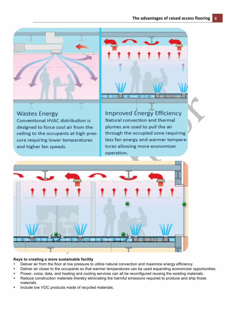
Energy savings In operation, an underfloor HVAC system operates at much lower pressure and warmer temperature than a traditional ducted overhead system, boosting indoor air quality, energy efficiency, and personal comfort control. These features help improve energy efficiency through the reduction of mechanical equipment and longer economizer hours. Reusing service supply materials such as wires, cables, outlets and diffusers during reconfiguration further improves the life-time sustainability of any facility. See some examples showing how they're used in high performance buildings.
The advantages of raised access flooring 5
Keys to creating a more sustainable facility • Deliver air from the floor at low pressure to utilize natural convection and maximize energy efficiency. • Deliver air closer to the occupants so that warmer temperatures can be used expanding economizer opportunities. • Power, voice, data, and heating and cooling services can all be reconfigured reusing the existing materials. • Reduce construction materials thereby eliminating the harmful emissions required to produce and ship those
materials. • Include low VOC products made of recycled materials.

The advantages of raised access flooring 6
Capital (First Cost) savings
In the construction phase, the Underfloor Service Distribution System allows a reduction in slab-to-slab height, decreasing construction materials required, eliminating ducts, wire and cable drop down lengths, and building shell materials.

The advantages of raised access flooring 7
Design phase guidelines and considerations
Although the number of publications on underfloor technology has been on the increase in recent years, until recently there were no standardized design guidelines for use by the industry. Designers having experience with underfloor systems had largely developed guidelines and practices of their own.
To address this situation, the American Society of Heating, Refrigerating, and Air-Conditioning Engineers (ASHRAE) initiated a research project to develop and publish a design guide on underfloor air distribution (UFAD) and task/ambient conditioning (TAC) systems. CBE completed this project in December of 2003, and the design guide is now available from ASHRAE. This section was developed before the completion of the Underfloor Air Distribution (UFAD) Design Guide published by ASHRAE. Please refer to the design guide for the most comprehensive and up-to-date guidelines.
UFAD vs. Conventional Overhead System Design
UFAD systems are quite similar to conventional overhead systems in terms of the types of equipment used at the cooling and heating plants and primary air handling units (AHU). Key differences arise with UFAD systems in their use of an underfloor air supply plenum, localized air distribution (with or without individual control) and the resulting floor-to-ceiling air flow pattern, and the solutions used for perimeter systems.
Although the methods used to calculate cooling and heating loads for a building with an UFAD system are similar to those used for conventional overhead systems, the calculation of design cooling air supply volumes requires different considerations. This is primarily due to the fact that overhead systems assume a single well-mixed temperature throughout the space (floor-to-ceiling), while UFAD systems assume that some amount of stratification occurs. The stratified floor-to-ceiling air flow pattern in UFAD systems allows most convective heat gains from sources outside the occupied zone (up to 1.8 m [6 ft]) to be exhausted directly at ceiling level, and therefore to not be included in the air-side load (see further discussion below). In order to successfully employ an UFAD and raised access floor system, it is essential that the implications of these differences be considered, starting at an early stage in the design process.

The advantages of raised access flooring 8
The following is a step-by-step list of issues to be considered, and decisions to be made, during the design process.
UFAD System Design Process:
1. Initial Building Design Considerations
1A. Building Section
In new construction, underfloor air distribution can achieve a 5-10% reduction in floor-to-floor heights compared to projects with ceiling-based air distribution. This is accomplished by reducing the overall height of service plenums and/or by changing from standard steel beam construction to a concrete (flat slab) structural approach (see example table and figure below). A single large overhead plenum to accommodate large supply ducts can be replaced with a smaller ceiling plenum for air return combined with a lower height underfloor plenum for unducted air flow and other building services. Concrete flat slab construction is more expensive than steel beam construction, but is preferred for underfloor systems due to thermal storage benefits as well as significantly reduced vertical height requirements. In the example shown in the figure, the underfloor/concrete configuration allows 0.25 m (10 in.) to be saved in floor-to-floor height compared to overhead/steel beam system design.
Even greater savings (up to 0.56 m [22 in.]) can be realized if the ceiling plenum is completely eliminated, exposing the concrete ceilings and providing an opportunity for greater architectural creativity. In this case, proper acoustic treatment must be incorporated into the new design.
Underfloor plenums accommodating both cable/electrical distribution and an UFAD system are often deeper than those employed solely for cable management purposes. However, the additional height required for acceptable air flow performance is not large, based on recent CBE research results [6].
The advantages of raised access flooring 9
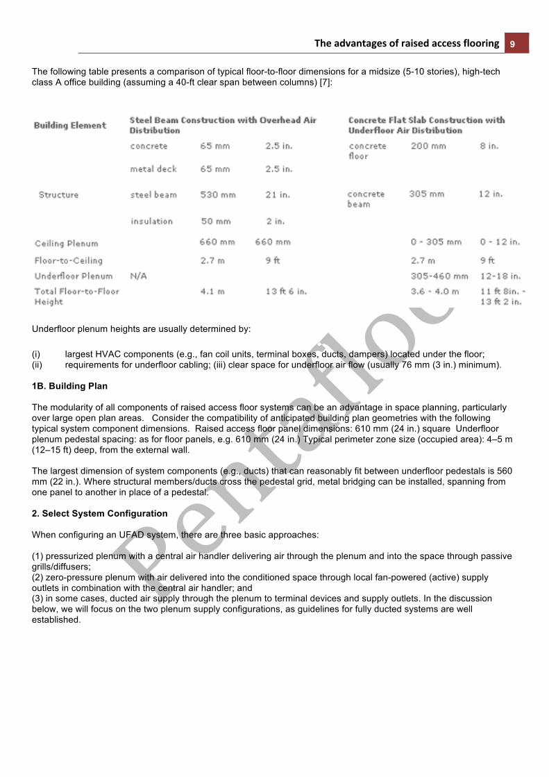
The following table presents a comparison of typical floor-to-floor dimensions for a midsize (5-10 stories), high-tech class A office building (assuming a 40-ft clear span between columns) [7]:
Underfloor plenum heights are usually determined by:
(i) largest HVAC components (e.g., fan coil units, terminal boxes, ducts, dampers) located under the floor; (ii) requirements for underfloor cabling; (iii) clear space for underfloor air flow (usually 76 mm (3 in.) minimum).
1B. Building Plan The modularity of all components of raised access floor systems can be an advantage in space planning, particularly over large open plan areas. Consider the compatibility of anticipated building plan geometries with the following typical system component dimensions. Raised access floor panel dimensions: 610 mm (24 in.) square Underfloor plenum pedestal spacing: as for floor panels, e.g. 610 mm (24 in.) Typical perimeter zone size (occupied area): 4–5 m (12–15 ft) deep, from the external wall. The largest dimension of system components (e.g., ducts) that can reasonably fit between underfloor pedestals is 560 mm (22 in.). Where structural members/ducts cross the pedestal grid, metal bridging can be installed, spanning from one panel to another in place of a pedestal. 2. Select System Configuration When configuring an UFAD system, there are three basic approaches: (1) pressurized plenum with a central air handler delivering air through the plenum and into the space through passive grills/diffusers; (2) zero-pressure plenum with air delivered into the conditioned space through local fan-powered (active) supply outlets in combination with the central air handler; and (3) in some cases, ducted air supply through the plenum to terminal devices and supply outlets. In the discussion below, we will focus on the two plenum supply configurations, as guidelines for fully ducted systems are well established.

The advantages of raised access flooring 10
2A. Pressurized Underfloor Plenum
Supply air that has been filtered and conditioned to the required temperature and humidity, and includes at least the minimum required volume of outside air, is delivered by a conventional air handling unit through a minimum amount of ductwork to the underfloor plenum. The number of plenum inlet locations is a function of the size of control zones, access points available in the building, amount of distribution ductwork used under the floor, and other design issues. Within the underfloor plenum, it is always desirable to the extent possible to have the supply air flow freely to the supply outlets. Pressurized plenums are designed to deliver supply air at constant temperature and volume to all passive outlets of the same size and control setting within the conditioned space. Because the supply air in the underfloor plenum is in direct contact with the concrete structural slab, a number of energy- and cost-saving strategies are possible with UFAD systems. Such thermal storage strategies should be implemented with great care. See further discussion under section 12 - Develop a Control Strategy. The underfloor thermal mass also has the effect of providing a consistent cool air temperature reservoir (for cooling applications), making UFAD systems extremely stable in their operation. Almost all available floor diffusers allow some amount of individual control (usually volume and in some cases direction) by nearby occupants. There are several approaches to address zones with significantly different thermal loads:
• plenum partitioning with ducted VAV devices supplying air to each zone; • plenum partitioning with fan-powered terminal devices supplying air to each zone; • thermostatically controlled VAV diffusers may be used in both partitioned and open plenums; • local fan-driven supply outlets may be used in both partitioned and open plenums; • open plenums with mixing boxes and ducted outlets.
Zoning and partitioning of the underfloor plenum should be kept to the minimum necessary to optimize UFAD performance and efficiency, as this helps to maintain the plenum for it's intended purpose: to serve as a highly flexible and accessible service plenum.
There is some evidence from completed projects that uncontrolled air leakage from the pressurized plenum can impair system performance. It is important that proper attention be given to the sealing of junctions between plenum partitions, slab, access floor panels, and exterior or interior permanent walls during the construction phase of the project. Due to the relatively low pressure (12.5 - 50 Pa [0.05 - 0.2 in. H2O]) used in pressurized plenums, proponents of pressurized plenums claim that leakage into adjacent zones is minimal, and much of the leakage (between raised floor panels) will be into the same conditioned zone of the building [5]. This is a design issue that is still in need of further investigation.
If access panels are removed for long periods of time, or the distance between primary air inlets and supply diffusers is too great, control of air flow will be diminished. Although not a requirement, some designers recommend limiting the size of underfloor zones (partitioned or otherwise) that are served by a single ducted primary air inlet, from the air handler (see below). This ensures the system's ability to avoid unacceptable variations in supply air temperature (due to heat gain from or loss to the concrete slab and raised floor structure) and quantity (due to pressure loss, obstructions, or friction) within the zone.
In some system designs, using multiple medium or small-sized (floor-by-floor) AHU’s can minimize or totally eliminate ductwork; and improve zone control when AHU capacities correspond to the specific requirements of each plenum zone. Some designs have resulted in higher pressures in the plenum on the order of 125 Pa (0.5 in. H2O); these have resulted in problems with over-conditioning, lifting of carpets, and problems with diffusers. Typical plenum pressure: 12.5 - 50 Pa (0.05 - 0.2 in. H2O) In some cases, maximum floor area served by each free-discharge supply air duct: 300 m2 (3,200 ft2)

The advantages of raised access flooring 11
2B. Zero-Pressure Underfloor Plenum
Primary supply air from the central air handler is delivered to the underfloor plenum in much the same manner as with pressurized plenums. In this case, since the plenum is maintained at very nearly the same pressure as the conditioned space, local fan-powered supply outlets are required to supply the air into the occupied zone of the space. Zero-pressure plenums pose no risk of uncontrolled air leakage to the conditioned space/adjacent zones. The removal of floor panels does not disrupt overall supply-air flow. Local fan-powered outlets under thermostatic or individual control allow supply air conditions to be controlled over a wide range as necessary. This controllability can be used to handle zones with significantly different thermal loads without underfloor partitioning. The use of partitioning for zone control can also be applied in a similar way as for pressurized plenums. Zoning and partitioning of the underfloor plenum should be kept to the minimum necessary to optimize UFAD performance and efficiency, as this helps to maintain the plenum for it's intended purpose: to serve as a highly flexible and accessible service plenum. Since the supply air in the underfloor plenum is in direct contact with the concrete structural slab, the same thermal storage strategies as with pressurized systems can be used (see section 12 - Develop a Control Strategy). Similarly, the frequency of ducted primary air inlets to the plenum must take into consideration the heat exchange between the supply air and the underfloor plenum structural mass.
By relying on both a primary air handler and local fan-powered outlets to draw air from the plenum into the space, zero-pressure configurations can more reliably maintain some amount of cooling effect if the chillers are off due to the thermal inertia of the concrete slab. The greater ability of zero-pressure systems to provide localized cooling suggests their suitability in projects involving high and diversified heat loads. In some system designs, using multiple medium or small-sized (floor-by-floor) AHU’s can minimize or totally eliminate ductwork; and improve zone control when AHU capacities correspond to the specific requirements of each plenum zone. Compliance with local Fire Codes may require sprinklers and partitioning to be installed in all plenum configurations.
3. Determine space cooling and heating loads
Cooling and heating loads for a building with an UFAD system are calculated in much the same manner as for a conventional overhead system. However, the determination of design cooling air quantities must take into account key differences between these systems.
3A. Cooling
The stratified floor-to-ceiling air flow pattern in UFAD systems allows most convective heat gains from sources outside the occupied zone (up to 1.8 m [6 ft]) to be exhausted directly at ceiling level, and therefore to not be included in the air-side load. Air supply volumes therefore only consider heat sources that enter and mix with air in the occupied zone. Heat sources must be analyzed based on their convective and radiative components, a subject addressed by [8]. Depending on the location of the heat source in the space, some amount of the convective portion can be neglected in this calculation. An overview of this design approach is described in [9]. Other issues that can affect load calculations include the heat exchange between the concrete slab and the supply air as it flows through the underfloor plenum. If the slab has absorbed heat, particularly from warm return air from the next floor down flowing along the underside of the slab, then supply temperature will increase with distance from the primary air inlet to the plenum. Supply air in the plenum will also be warmed by heat transfer from the room through the raised floor panels. Estimates of supply air temperature rise as a function of air travel distance in an underfloor plenum are given in [10]. This is also the subject of ongoing CBE research. Another difference between UFAD design and overhead systems is consideration of heat loss through the access floor. This adds another component to the space cooling load calculation –- estimated to be as high as 0.1 W/m2 (1 W/ft2). Most of this heat transferred through the floor into the supply air stream will reenter the conditioned space, although not instantaneously due to the mass of the floor panels. Research indicates that stratification for UFAD systems can result in overall delta T's (return-supply temperature difference) in the range of 8-11°C (15-20°F), for properly designed systems. However, these values are not what determine the air flow requirement. The heat gain to the occupied zone and the air flow required to maintain a given comfort condition in that zone is what determines the actual air flow requirements, and consequently the overall delta T that will be developed. Typically this results in air flow rates that can be equal to or less than that for overhead systems, even for higher supply air temperatures.

The advantages of raised access flooring 12
3B. Heating
In most applications, heating is primarily needed only near the building envelope where cold downdrafts from perimeter glass may cause discomfort. Heating may also be needed in some top floor interior zones and during periods of low occupancy (e.g., nights and weekends). Effective heating systems isolate the source of warm air from the thermal lag effect of the concrete slab (which is usually slightly cooler than room temperature). This can be done, for example, by ducting from an underfloor fan coil unit, or by using baseboard radiation or convection units. Quick response on heating can be very important during morning startup.
4. Zoning
4A. Perimeter Zones
The largest loads typically occur near the skin of the building. Since these areas are influenced by climatic variations, rapid fluctuations in heating and cooling demands can happen, with peak loads often occurring only for several hours per day and relatively few days of the year. Energy-efficient envelope design is always the first stage of defense against excessive perimeter loads. Under cooling conditions, the warm interior surface temperatures at the perimeter (due to either highly absorptive glazing or intercepted solar radiation if blinds are present) will form a strong vertical plume that can be removed with only part of the load contributing to the air-side load. Perimeter zone considerations often lead to hybrid system designs in which active, fan-powered supply units are used to increase the rate at which the system can respond to changes in load. Many perimeter zone solutions have been successfully applied in practice (see Plan Views for a few examples). Some manufacturers offer equipment and recommended configurations for perimeter systems [10, 11].
4B. Interior Zones
Interior zones (defined as areas located further than 5 m (15 ft) from exterior walls) are usually exposed to relatively constant and lower (compared to perimeter zones) thermal loads (almost always cooling in typical office buildings). However, with modern energy efficient office equipment and high diversity rates of personnel, these loads can fluctuate significantly; control strategies and system design need to be well thought out to accommodate these conditions. These zones can often be well served by a constant volume, or constant pressure in a pressurized system, control strategy. The need for dynamic control of these (typically) large zones is minimized due to the ability of occupants to make small local adjustments to individual diffusers. This configuration with a minimum amount of underfloor partitioning helps to maintain flexibility in the relocation of other services (e.g., cabling). The interaction between interior and perimeter systems needs careful consideration. For example, if plenum air is used to supply cooling for perimeter zones, reset of SAT for the core zones may militate against being able to satisfy perimeter load conditions.
4C. Other Special Zones
Other special zones having large and rapid changes in cooling load requirements, such as conference rooms or lecture halls, should incorporate fan-powered or VAV air supply solutions. This can require underfloor partitioning for these areas. Automatic controls to these zones should be capable of meeting both peak demand and significant turndown during periods of little or no occupancy. Manual control of these zones has also been used in some installations. Partition construction: Vertical sheet metal dividers Perimeter zone dimensions: Typically extending 4 – 5 m (12 – 15 ft) from external wall.
The advantages of raised access flooring 13
5. Determine ventilation air requirements
Minimum outside air requirements should be determined according to applicable codes (e.g., ASHRAE Standard 62-1999). Some improvement in ventilation effectiveness is expected by delivering the fresh supply air near the occupant at floor or desktop level, allowing an overall floor-to-ceiling air flow pattern to more efficiently remove contaminants from the occupied zone of the space. An optimized strategy is to control supply outlets to allow mixing of supply air with room air up to a height no higher than head level (6 ft [1.8 m]). Above this height, stratified and more polluted air is allowed to occur. The air that the occupant breathes will have a lower percentage of pollutants compared to conventional uniformly mixed systems. If an enhanced air change effectiveness can be shown to exist in comparison to well-mixed overhead systems (see ASHRAE Standard 129-1997) future versions of ASHRAE Standard 62 may allow some credit to be taken, thereby allowing reduced ventilation air quantities. The magnitude of this improved air change effectiveness will be largest during times of outside-air economizer use. The fact that the number of hours of economizer operation is typically greater for UFAD systems also contributes to overall increased ventilation effectiveness.
6. Determine zone supply air temperature and flow rate
Because the air is supplied directly into the occupied zone, supply air temperatures must be warmer than that used for conventional overhead system design. For cooling applications, supply air temperatures at the diffusers should be maintained no lower than in the range of 17 – 20°C (63 – 68°F) to avoid overcooling nearby occupants. This supply temperature can be reset even higher under partial load conditions. Mixed air temperature after the cooling coil, or plenum inlet temperature, must be determined by taking into account temperature increase (or decrease, depending on the slab temperature) as the air flows through the underfloor plenum. Current estimates for typical air flow rates in an underfloor plenum with a slab that is 3°C (5°F) warmer than the plenum inlet air temperature call for a 1°C (2°F) increase for every 10 m (33 ft) of distance traveled through the plenum. In temperate climates, where high humidity is not a problem, these warmer supply air temperatures increase the potential for economizer use, and allow higher cooling coil temperatures to be set, if desired. Cooling air quantities for UFAD systems should be carefully determined. Higher supply air temperatures would suggest that higher supply air volumes are required, but the higher return temperatures created by stratification reduce the required increase in volume. Finally, as previously described, a calculation of the portion of heat sources that bypass the occupied zone in the space allows cooling air quantities to be further reduced. The net effect is that for most designs, controlled stratification in the space allows cooling air quantities for UFAD systems to be equal to or less than those required under the same conditions using overhead air distribution. As discussed further below under controls, control strategies for temperature and flow rate will vary depending on the magnitude and variability of loads in each control zone, as well as other system design issues. Supply air temperature - Return air temperature UFAD 17-20°C (63-68°F) - 25-30°C (77-86°F) Systems Overhead 13°C (55°F) - 24°C (75°F) Systems
7. Determine return air configuration
For optimal cooling operation of a UFAD system, it is important to locate return grills at ceiling level, or at a minimum, above the occupied zone (1.8 m [6 ft]). Air is typically returned through grilles located in a suspended ceiling or through high side-wall grilles if no ceiling plenum is present. This supports an overall floor-to-ceiling air flow pattern that takes advantage of the natural buoyancy produced by heat sources in the office and more efficiently removes heat loads and contaminants from the space. A certain portion of return air is mixed with primary air from the AHU to achieve desired air temperatures and humidity, and enable reduced energy costs. In many climates to achieve proper humidity control, conventional cooling coil temperatures must be used (producing a coil leaving temperature of 12.8°C (55°F)). In this situation, a return air bypass control strategy can be employed in which a portion of the return air is bypassed around the cooling coil and then mixed with the air leaving the coil to produce the desired warmer supply air temperature (17-20°C [63-68°F]). In some cases, a percentage of return air can be re-circulated directly back into the underfloor plenum via return shafts near the ceiling or from the ceiling plenum. Room air flowing back into the plenum through open floor grills can also serve as make-up air for zero pressure plenum designs when local fan-powered outlets require more air than that being supplied from the central AHU. If re-circulation takes place directly in the underfloor plenum, the supply and return air streams must be well mixed within the underfloor plenum before delivery to the conditioned space. This can usually be achieved by distributing the primary air at regularly spaced intervals throughout the plenum, and/or employing fan-powered local supply units to aid mixing of primary supply air with the return air.

The advantages of raised access flooring 14
8. Calculate cooling coil load
The calculation of cooling coil load is done in much the same manner as for a conventional mixing-type air distribution system. All of the loads in the space (some of which have bypassed the occupied zone, allowing a reduction in cooling air-side loads) must be handled at the coil. Humidity control considerations require that, in more humid climates the cooling coil be operated to produce the necessary dehumidification of outside air resulting in a coil leaving air temperature of 12.8°C (55°F). This air is then mixed with warmer bypassed return air to produce the desired plenum inlet air temperature. It is important that these systems use enthalpy based economizer control to ensure proper supply air humidity control. In temperate climates, the warmer supply air temperatures of UFAD systems increase the potential for economizer use and may also allow higher cooling coil temperatures than for conventional overhead systems, thereby increasing chiller efficiencies.
9. Layout ducts and plenum configuration
Underfloor ducts serving specific zones should be sized to accommodate peak cooling loads. The capacity of the central chiller plant, air handlers and main duct risers can generally be reduced by accounting for time variations and load diversity (up to 50%). The design and layout of main ducts from the central plant to plenum inlet locations is similar to that of conventional overhead systems except that access must be provided for the ducts to reach the underfloor plenum. The amount of main ductwork can be reduced in designs using medium to small-sized air handlers (floor-by-floor units) that are located closer to the point of use. However, ductwork for ventilation air is still required and must be sized accordingly if the use of an outside-air economizer will be an important operating strategy. The amount of re-circulation ductwork can be reduced by taking some of the return air at ceiling level directly back into the underfloor plenum without returning to the air handler. For example, return air can be brought down induction shafts formed with furring spaces along structural columns. This alternative configuration of bypass control can be used as long as proper dehumidification is maintained back at the air handler and complete blending of return and supply air is achieved within the underfloor plenum. The height of underfloor plenums is generally determined by the largest HVAC components located under the floor. These components can typically be distribution ductwork, fire dampers at plenum inlets, fan coil units, and terminal boxes. Commercially available HVAC products allow plenum configurations as low as 0.2 m (8 in.), although heights in the range of 0.31-0.46 m (12-18 in.) are more common. In pressurized plenums as low as 0.2 m (8 in.), full-scale experiments have demonstrated that static pressure remains very uniform across the entire plenum, making balancing of individual diffusers unnecessary [6]. These same experiments also showed that solid obstructions, even with only 38 mm (1.5 in.) of clear space above them, may be located in a 0.2-m (8-in.) or higher plenum and have very little impact on the uniformity of the overall pressure and air flow distribution. In both zero-pressure and pressurized plenums, the delivery of air through fan-powered outlets is even more reliable than that through passive diffusers in pressurized plenums. Active diffusers are less susceptible to pressure variations (such as when access floor panels are removed) and other flow restrictions.
10. Select primary HVAC equipment
Due to the low operational static pressures in underfloor air supply plenums (typical pressures are around 25 Pa (0.1 in. H2O)), central fan energy use and sizing can potentially be reduced relative to traditional ducted overhead air distribution systems depending on the design strategy adopted (see [12] for a more complete discussion of this issue). As discussed earlier, cooling air quantities, and therefore air handler capacities, for UFAD systems should be carefully determined and may be equal to or less than those required under the same conditions using overhead systems. Although the total space cooling load is similar for both UFAD and conventional overhead systems, higher supply and return air temperatures in UFAD systems allow higher efficiency chillers to be used, when suitable weather conditions, and in particular humidity conditions, prevail. Thermal storage strategies using nighttime precooling of the concrete slab in the plenum can reduce peak demand for mechanical cooling during the following day, thereby allowing refrigeration equipment to be downsized.
11. Select and locate diffusers
The flexibility of mounting supply diffusers in movable raised access floor panels is a major advantage for UFAD systems. The inherent ability to easily move diffusers to more closely match the distribution of loads in the space makes the placement of diffusers a much easier task. In fact, initial layout can be done quite crudely. Final placement can take place after the location of furniture and loads, as well as the preferences of individual occupants, are more accurately determined.
The advantages of raised access flooring 15
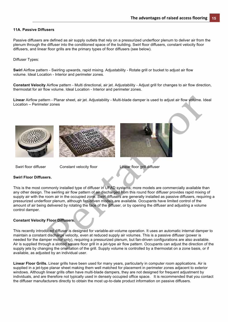
11A. Passive Diffusers
Passive diffusers are defined as air supply outlets that rely on a pressurized underfloor plenum to deliver air from the plenum through the diffuser into the conditioned space of the building. Swirl floor diffusers, constant velocity floor diffusers, and linear floor grills are the primary types of floor diffusers (see below).
Diffuser Types:
Swirl Airflow pattern - Swirling upwards, rapid mixing. Adjustability - Rotate grill or bucket to adjust air flow volume. Ideal Location - Interior and perimeter zones.
Constant Velocity Airflow pattern - Multi directional, air jet. Adjustability - Adjust grill for changes to air flow direction, thermostat for air flow volume. Ideal Location - Interior and perimeter zones.
Linear Airflow pattern - Planar sheet, air jet. Adjustability - Multi-blade damper is used to adjust air flow volume. Ideal Location – Perimeter zones
Swirl floor diffuser Constant velocity floor Linear floor grill diffuser
Swirl Floor Diffusers.
This is the most commonly installed type of diffuser in UFAD systems; more models are commercially available than any other design. The swirling air flow pattern of air discharged from this round floor diffuser provides rapid mixing of supply air with the room air in the occupied zone. Swirl diffusers are generally installed as passive diffusers, requiring a pressurized underfloor plenum, although fan-driven models are available. Occupants have limited control of the amount of air being delivered by rotating the face of the diffuser, or by opening the diffuser and adjusting a volume control damper.
Constant Velocity Floor Diffusers.
This recently introduced diffuser is designed for variable-air-volume operation. It uses an automatic internal damper to maintain a constant discharge velocity, even at reduced supply air volumes. This is a passive diffuser (power is needed for the damper motor only), requiring a pressurized plenum, but fan-driven configurations are also available. Air is supplied through a slotted square floor grill in a jet-type air flow pattern. Occupants can adjust the direction of the supply jets by changing the orientation of the grill. Supply volume is controlled by a thermostat on a zone basis, or if available, as adjusted by an individual user.
Linear Floor Grills. Linear grills have been used for many years, particularly in computer room applications. Air is supplied in a jet-type planar sheet making them well matched for placement in perimeter zones adjacent to exterior windows. Although linear grills often have multi-blade dampers, they are not designed for frequent adjustment by individuals, and are therefore not typically used in densely occupied office space. It is recommended that you contact the diffuser manufacturers directly to obtain the most up-to-date product information on passive diffusers.
The advantages of raised access flooring 16
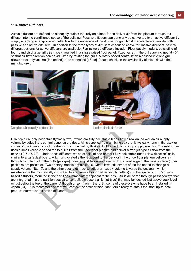
11B. Active Diffusers
Active diffusers are defined as air supply outlets that rely on a local fan to deliver air from the plenum through the diffuser into the conditioned space of the building. Passive diffusers can generally be converted to an active diffuser by simply attaching a fan-powered outlet box to the underside of the diffuser or grill. Most manufacturers provide both passive and active diffusers. In addition to the three types of diffusers described above for passive diffusers, several different designs for active diffusers are available. Fan-powered diffusers include: Floor supply module, consisting of four round discharge grills (jet-type) mounted in a single raised floor panel. Fixed vanes in the grills are inclined at 40°, so that air flow direction can be adjusted by rotating the grills. A rotary speed control knob recessed into one grill allows air supply volume (fan speed) to be controlled [13-19]. Please check on the availability of this unit with the manufacturer.
Desktop air supply pedestals (typically two), which are fully adjustable for air flow direction, as well as air supply volume by adjusting a control panel on the desk. Air is supplied from a mixing box that is typically hung in the back or corner of the knee space of the desk and connected by flexible duct to the two desktop supply nozzles. The mixing box uses a small variable-speed fan to pull air from the underfloor plenum and deliver a free-jet-type air flow from the nozzles [15, 18-22]. Under-desk diffusers, which consist of one or more fully adjustable (for air flow direction) grills, similar to a car's dashboard. A fan unit located either adjacent to the desk or in the underfloor plenum delivers air through flexible duct to the grills (jet-type) mounted just below and even with the front edge of the desk surface (other positions are possible). Two primary models are available. One allows adjustment of the fan speed to change air supply volume [18, 19], and the other uses a damper to adjust air supply volume towards the occupant while maintaining a thermostatically controlled total volume (through other supply outlets) into the space [23]. Partition-based diffusers, mounted in the partitions immediately adjacent to the desk. Air is delivered through passageways that are integrated into the partition design to controllable supply grills (jet-type) that may be located just above desk level or just below the top of the panel. Although uncommon in the U.S., some of these systems have been installed in Japan [24]. It is recommended that you contact the diffuser manufacturers directly to obtain the most up-to-date product information on active diffusers.

The advantages of raised access flooring 17
12. Develop control strategy
12a Temperature, humidity, and volume control
As described earlier, since air is supplied directly into the occupied zone near floor level, supply outlet temperatures should be maintained no cooler than in the range of 17-20°C (63-68°F) to avoid overcooling nearby occupants. To achieve the required higher supply air temperatures while still maintaining humidity control the following approach, called side-stream bypass, is often used. Cooling coil temperatures are typically in the range of 10-13°C (50-55°F) for dehumidification purposes. Only the incoming outside air and a portion of the return air is dehumidified (minimum amount needed for humidity control). The remaining return air is bypassed around the coil, if done at the air handler, and mixed with the cool primary air to produce supply air of the proper temperature and humidity before being delivered directly into the underfloor plenum. In this configuration, a range of coil temperatures can be produced, including low temperature air systems with or without ice storage. An alternative bypass configuration involves re-circulating some of the return air directly back into the underfloor plenum where it is mixed with the cool primary air from the air handler. In this case, it is very important to ensure thorough mixing of primary and return air in the plenum. In less humid climates, the warmer supply air temperatures increase the potential for economizer use and may also allow higher cooling coil temperatures to be used, thereby increasing chiller efficiencies. A variety of operating strategies have been used in existing installations. A preferred method for interior zones is constant air volume, variable temperature (CAV-VT). Supply temperature is controlled based on zone thermostats. Occupants can make minor changes to local comfort conditions by adjusting a diffuser. Due to temperature stratification that naturally occurs with UFAD systems, thermostats should be carefully placed and their readings correlated with acceptable comfort conditions in the occupied zone. For example, if stratification is large, an acceptable temperature at the five-foot level may in fact coincide with uncomfortably cool temperatures at the ankle level. While the floor supply system is very well matched to the stable load profiles in most interior building zones, it is incompatible with the more rapidly varying loads found in perimeter and other special zones. These zones require a separate system, or at least a hybrid solution in which fan-powered outlets and/or additional equipment are used to address the extra heating and cooling requirements of these zones. Perimeter zone operation can be either variable air volume (VAV) or CAV-VT, but in either case must be able to respond to the special cooling and heating demands of these zones. Perimeter zone solutions have not been standardized in existing UFAD installations; many different approaches have been used.
12B. Thermal storage control strategies
Since supply air flowing through the underfloor plenum is in direct contact with the concrete floor slab of the building, control strategies must consider thermal storage in the slab as well as other mass in the plenum (e.g., floor panels). UFAD systems are very stable in operation with only gradual (usually unnoticeable to occupants) changes in supply temperature over time, unless the supply air is isolated from the mass. Energy and operating cost savings can be achieved using a thermal storage strategy in the concrete slab. In temperate climates, cool nighttime air can be brought into the underfloor plenum where it effectively cools the slab overnight. During the following day's cooling operation, higher supply air temperatures can be used to meet the cooling demand, thereby reducing refrigeration loads for at least part of the day. This 24-hour thermal storage strategy benefits from lower off-peak utility rates and extends the hours of economizer operation. For this strategy to be successful, the following issues must be addressed:
• Heating night setback must be used. • Since a precooled slab will be at its coolest temperature in the morning, the design, capacity, and response
rate of the heating system, if needed, will be particularly important under morning startup conditions. • Enthalpy-based economizer control must be used to maintain proper humidity levels of the incoming nighttime
air and to protect against condensation in the plenum. • Lower limit control switches for both slab and space temperatures must be activated to prevent overcooling. • Preliminary estimates indicate that a precooled slab is most effective at reducing daytime cooling loads during
morning hours only. • If the slab is not pre-cooled at night, then supply outlet temperatures will likely increase with distance from the
primary air inlet to the plenum due to the effects of stored heat in the slab (particularly from warm return air from the next floor down flowing along the underside of the slab). CBE is currently conducting research to investigate the thermal storage performance of underfloor air supply plenums.
The advantages of raised access flooring 18
13. References [1] Bauman, F.S., and E.A. Arens. 1996. “Task/ambient conditioning systems: Engineering and application guidelines.” Center for Environmental Design Research, University of California, Berkeley. [2] McCarry, B.T. 1995. “Underfloor air distribution systems: Benefits and when to use the system in building design.” ASHRAE Transactions, Vol. 101 (2). [3] Shute, R.W. 1995. “Integrated access floor HVAC: Lessons learned.” ASHRAE Transactions, Vol. 101 (2). [4] Houghton, D. 1995. “Turning air conditioning on its head: Underfloor air distribution offers flexibility, comfort, and efficiency.” E Source Tech Update TU-95-8, E Source, Inc., Boulder, Colo., August, 16 pp. [5] Sodec, F., and R. Craig. 1991. Underfloor air supply system: Guidelines for the mechanical engineer. Report No. 3787A. Aachen, West Germany: Krantz GmbH & Co., January. [6] Bauman, F., P. Pecora, and T. Webster. 1999. How low can you go? Air flow performance of low-height underfloor plenums. Center for the Built Environment, University of California, Berkeley, October. [7] John Kerley. 2000. Personal communication. Webcor Builders, San Mateo, CA. [8] Hosni, M.H., B.W. Jones, and H. Xu. 1999. “Experimental results for heat gain and radiant/convective split from equipment in buildings.” ASHRAE Transactions, 105 (1). [9] Loudermilk, K. 1999. "Underfloor air distribution solutions for open office applications." ASHRAE Transactions, Vol. 105 (1). [10] York International. 1999. York Modular Integrated Terminals: Convection Enhanced Ventilation – Technical Manual. York International, York, PA. [11] Trox International. 2000. Trox Underfloor Air Design Manual. Trox USA, Alpharetta, GA. [12] Webster, T., E. Ring, and F. Bauman. 2000. "Supply fan energy use in pressurized underfloor plenum systems." Center for the Built Environment, University of California, Berkeley, October. [13] Bauman, F.S., L. Johnston, H. Zhang, and E. Arens. 1991. "Performance testing of a floor-based, occupant-controlled office ventilation system." ASHRAE Transactions, Vol. 97, Pt. 1. [14] Fisk, W.J., D. Faulkner, D. Pih, P. McNeel, F. Bauman, and E. Arens. 1991. "Indoor air flow and pollutant removal in a room with task ventilation." Indoor Air, No. 3, pp. 247-262. [15] Fountain, M., E. Arens, R. de Dear, F. Bauman, and K. Miura. 1994. "Locally controlled air movement preferred in warm isothermal environments." ASHRAE Transactions, Vol. 100, Pt. 2, 14 pp. [16] Bauman, F.S., E.A. Arens, S. Tanabe, H. Zhang, and A. Baharlo. 1995. "Testing and optimizing the performance of a floor-based task conditioning system." Energy and Buildings, Vol. 22, No. 3, pp. 173-186. [17] Faulkner, D., W.J. Fisk, and D.P. Sullivan. 1995. "Indoor air flow and pollutant removal in a room with floor-based task ventilation: results of additional experiments." Building and Environment, Vol. 30, No. 3, pp. 323-332. [18] Tsuzuki, K., E.A. Arens, F.S. Bauman, and D.P. Wyon. 1999. "Individual thermal comfort control with desk-mounted and floor-mounted task/ambient conditioning (TAC) systems." Proceedings of Indoor Air 99, Edinburgh, Scotland, 8-13 August. [19] Bauman, F., K. Tsuzuki, H. Zhang, T. Stockwell, C. Huizenga, E. Arens, and A. Smart. 1999. "Experimental Comparison of Three Individual Control Devices: Thermal Manikin Tests." Final Report. Center for Environmental Design Research, University of California, Berkeley. [20] Bauman, F.S., H. Zhang, E. Arens, and C. Benton. 1993. "Localized comfort control with a desktop task conditioning system: laboratory and field measurements." ASHRAE Transactions, Vol. 99, Pt. 2. [21] Bauman, F., G. Carter, A. Baughman, and E. Arens. 1998. "Field Study of the Impact of a Desktop Task/Ambient Conditioning System in Office Buildings." ASHRAE Transactions, Vol. 104, Pt. 1. [22] Faulkner, D., W.J. Fisk, and D.P. Sullivan. 1993. "Indoor air flow and pollutant removal in a room with desktop ventilation." ASHRAE Transactions, Vol. 99, Pt. 2. [23] Bauman, F., V. Inkarojrit, and H. Zhang. 2000. "Laboratory test of the Argon personal air-conditioning system (APACS)." Center for Environmental Design Research, University of California, Berkeley, April. [24] Matsunawa, K., H. Iizuka, and S. Tanabe. 1995. "Development and application of an underfloor air conditioning system with improved outlets for a smart building in Tokyo." ASHRAE Transactions, Vol. 101, Pt. 2.

The advantages of raised access flooring 19
Construction Phase Guidelines
Underfloor air distribution (UFAD) systems require good coordination between all building trades throughout the design and construction process. Shute (1995) provides an excellent list of recommendations for the design and construction of underfloor air distribution systems. McCarry (1995) also describes some guidelines based on his experiences with UFAD system installation. More recently, Bauman (2003) discusses guidelines for a well-coordinated construction sequence.
Shown below is a partial list of recommendations for design and construction.
• It is essential that the implications of the raised access floor be considered early in the design process. • The concrete slab surface must be sealed to reduce dust, and the underfloor plenum and floor panels must be
thoroughly • cleaned both during installation of the access floor and again before occupancy. • The height of the access floor and the placement of the 0.6 m x 0.6 m (2 ft x 2 ft) raised floor pedestal grid is
critical with respect to locating all underfloor service installations. • It is important to lay out underfloor equipment requiring regular maintenance to be located in accessible areas,
such as corridors, not underneath furniture and partitions. • In partitioned office spaces, offset the partition grid from the floor grid so that partitions do not cover joints
between floor panels, thereby preventing access to the underfloor plenum on both sides of the partition. • Consider dead load allowance and seismic bracing of the access floor. • Determine areas in the building with no access floor and allow for transitions to areas with access flooring. • In pressurized underfloor air distribution systems, greater care must be taken during construction to seal the
underfloor plenum to prevent uncontrolled air leakage. • Designers must consider that fan rooms or access for HVAC distribution will be required at more frequent intervals
than with conventional air distribution systems. • If called for, return air shafts must be designed between the ceiling and the underfloor plenum, usually around
columns or other permanent building elements. • The main structural slab, the traditional working platform, will not be available continuously during construction,
and therefore a well coordinated construction sequence is necessary (see Shute 1995).
The advantages of raised access flooring 20
References [1] Bauman, F. 2003. Underfloor air distribution (UFAD) design guide. Atlanta: ASHRAE, Inc. [2] McCarry, B.T. 1995. Underfloor air distribution systems: Benefits and when to use the system in building design. ASHRAE Transactions 101 (pt. 2). [3] Shute, R.W. 1995. Integrated access floor HVAC: Lessons learned. ASHRAE Transactions 101 (pt. 2). Occupant health and comfort Thermal Comfort in UFAD Systems
Background
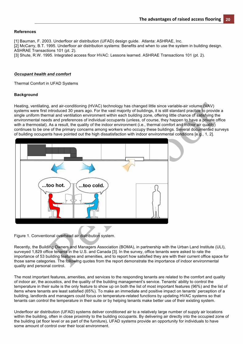
Heating, ventilating, and air-conditioning (HVAC) technology has changed little since variable-air volume (VAV) systems were first introduced 30 years ago. For the vast majority of buildings, it is still standard practice to provide a single uniform thermal and ventilation environment within each building zone, offering little chance of satisfying the environmental needs and preferences of individual occupants (unless, of course, they happen to have a private office with a thermostat). As a result, the quality of the indoor environment (i.e., thermal comfort and indoor air quality) continues to be one of the primary concerns among workers who occupy these buildings. Several documented surveys of building occupants have pointed out the high dissatisfaction with indoor environmental conditions [e.g., 1, 2].
Figure 1. Conventional overhead air distribution system.
Recently, the Building Owners and Managers Association (BOMA), in partnership with the Urban Land Institute (ULI), surveyed 1,829 office tenants in the U.S. and Canada [3]. In the survey, office tenants were asked to rate the importance of 53 building features and amenities, and to report how satisfied they are with their current office space for those same categories. The following quotes from the report demonstrate the importance of indoor environmental quality and personal control.
The most important features, amenities, and services to the responding tenants are related to the comfort and quality of indoor air, the acoustics, and the quality of the building management’s service. Tenants’ ability to control the temperature in their suite is the only feature to show up on both the list of most important features (96%) and the list of items where tenants are least satisfied (65%). To make an immediate and positive impact on tenants’ perception of a building, landlords and managers could focus on temperature-related functions by updating HVAC systems so that tenants can control the temperature in their suite or by helping tenants make better use of their existing system.
Underfloor air distribution (UFAD) systems deliver conditioned air to a relatively large number of supply air locations within the building, often in close proximity to the building occupants. By delivering air directly into the occupied zone of the building (at floor level or as part of the furniture), UFAD systems provide an opportunity for individuals to have some amount of control over their local environment.

The advantages of raised access flooring 21
Figure 2. Underfloor air distribution system
Thermal Comfort Standards
Current comfort standards, ASHRAE Standard 55-1992 [4] and ISO Standard 7730 [5], specify a “comfort zone,” representing the optimal range and combinations of thermal factors (air temperature, radiant temperature, air velocity, humidity) and personal factors (clothing and activity level) with which at least 80% of the building occupants are expected to express satisfaction. These standards are based on a large number of laboratory studies in which subjects (primarily university students) were asked to evaluate their comfort in steady-state environments over which they had little or no control. The standards were developed for mechanically conditioned buildings typically having overhead air distribution systems designed to maintain uniform temperature and ventilation conditions throughout the occupied space.
Given the high value placed on the quality of indoor environments, it is rather astonishing that a building HVAC system can be considered in compliance with thermal comfort standards, and yet provide a thermal environment with which up to 20% of the building population will be dissatisfied. This is, however, exactly the case in the conventional "one-size-fits-all" approach to environmental control in buildings. The primary scientific justification for this seemingly low level of occupant satisfaction is clearly revealed in the large body of thermal comfort research on human subjects in a laboratory setting. These tests, which form the basis for the ASHRAE Standard 55 comfort zone, demonstrate that on average at least 10% of a large population of subjects will express dissatisfaction with their thermal environment, even when exposed to the same uniform thermal environment considered acceptable by the majority of the population. In practice, the standard uses a 20% dissatisfaction rating by adding an additional safety factor of 10% dissatisfaction that might arise from locally occurring non-uniform thermal conditions in the space (e.g., stratification, draft, radiant asymmetry). Furthermore, there is an ongoing debate about the degree of relevance of laboratory-based research for occupants in real buildings, where the range of individual thermal preferences will likely be even greater (see discussion below).

The advantages of raised access flooring 22
The bottom line is that no matter how well controlled an HVAC system is in a building using overhead air distribution, there may be a surprisingly large number of occupants who will not be satisfied with the thermal environment. Air velocity is one of the six main factors affecting human thermal comfort. Because of its important influence on skin temperature, skin wettedness, convective and evaporative heat loss, and thermal sensation, it has always been incorporated into thermal comfort standards. In ASHRAE Standard 55, there are two recommendations for allowable air velocities in terms of (1) minimizing draft risk and (2) providing desirable occupant cooling [6]. The elimination of draft is addressed by placing rather stringent limits on the allowable mean air speed as a function of air temperature and turbulence intensity (defined as the standard deviation of fluctuating velocities divided by their mean for the measuring period). As an example, the draft risk data (representing 15% dissatisfaction curves) for a turbulence intensity of 40% (typical of indoor office environments) would restrict the mean air speed to 0.12 m/s (24 fpm) at 20°C (68°F) and 0.2 m/s (40 fpm) at 26°C (78.8°F). These extremely low velocity limits taken by themselves would make it very difficult for UFAD systems to be considered acceptable due to the higher local air velocities that are possible when air is introduced directly into the occupied zone. The draft risk data are based solidly on laboratory research conducted over the lower end of the comfort zone temperature range (23°C [73.5°F] and below), but are represented as extrapolations to conditions where data were not collected at higher temperatures. Although it is still under debate, the draft risk velocity limits in Standard 55 appear to be most suitable for eliminating undesirable air movement under cooler (heating mode) environmental conditions, a more frequent situation in European climates.
In warmer climates, such as those frequently found in the U.S. (and South Africa), air motion is often considered as highly desirable for both comfort (cool breeze for relief) and air quality (preventing stagnant air) reasons. ASHRAE Standard 55 allows local air velocities to be higher than the low values specified for draft avoidance if the affected occupant has individual control over these velocities. By allowing personal control of the local thermal environment, UFAD systems satisfy the requirements for higher allowable air velocities contained in Standard 55 and have the potential to satisfy all occupants.
Personal Control
One of the greatest potential improvements of UFAD systems over conventional overhead systems is in the area of occupant thermal comfort, in that individual preferences can be accommodated. In today’s work environment, there can be significant variations in individual comfort preferences due to differences in clothing, activity level (metabolic rate), and individual preferences. In terms of clothing variations, if a person reduced their level of clothing from a business suit (0.9 clo) to slacks and a short-sleeved shirt (0.5 clo), the room temperature could be increased by approximately 2°C (4°F) and still maintain equivalent comfort. As an example of the variations in activity level that commonly occur, a person walking continuously around in an office (1.7 met) will experience an effective temperature of the environment that is approximately 2 to 3°C (3 to 5°F) warmer than that for a person sitting quietly at their desk (1.0 met), depending on clothing level.
How much control is needed?
Considering the magnitude of variations described above, a range of control up to 3°C (5°F) is probably enough for most applications. Recent laboratory tests have shown that commercially available fan-powered supply outlets provide personal cooling control of equivalent whole-body temperature over a sizable range: up to 7°C (13°F) of sensible cooling for desktop-mounted outlets (Figure 3) and up to 5°C (9°F) of sensible cooling for floor-based outlets (Figure 4) [7, 8]. This amount of control is clearly more than enough to allow individual thermal preferences to be
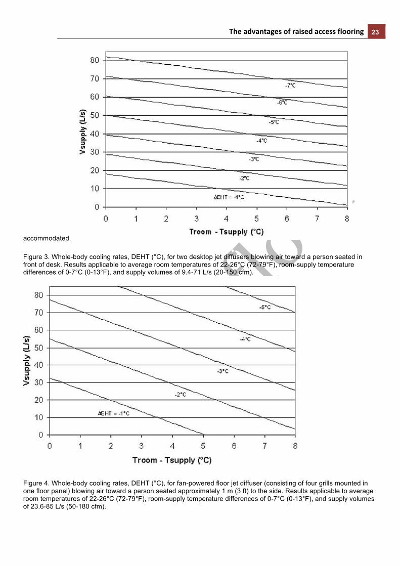
The advantages of raised access flooring 23
accommodated.
Figure 3. Whole-body cooling rates, DEHT (°C), for two desktop jet diffusers blowing air toward a person seated in front of desk. Results applicable to average room temperatures of 22-26°C (72-79°F), room-supply temperature differences of 0-7°C (0-13°F), and supply volumes of 9.4-71 L/s (20-150 cfm).
Figure 4. Whole-body cooling rates, DEHT (°C), for fan-powered floor jet diffuser (consisting of four grills mounted in one floor panel) blowing air toward a person seated approximately 1 m (3 ft) to the side. Results applicable to average room temperatures of 22-26°C (72-79°F), room-supply temperature differences of 0-7°C (0-13°F), and supply volumes of 23.6-85 L/s (50-180 cfm).

The advantages of raised access flooring 24
The tests described in refs. 7 and 8 were conducted using an advanced thermal manikin to measure the rate of heat loss from a person under realistic conditions. The manikin was dressed in typical clothing and it maintained a constant skin temperature distribution that was characteristic of a person in thermal neutrality at all times. Whole-body rates of heat loss from the manikin are represented in terms of an Equivalent Homogeneous Temperature (EHT).
EHT is defined as the temperature of a uniform space, in which all surface temperatures are equal to air temperature, there is no air movement other that the self-convection of the manikin, and the rate of heat loss would be the same as was actually measured. In Figures 3 and 4, a value of DEHT = -3°C (-5°F) is the same amount of cooling that would be obtained by walking out of one room with homogeneous temperature and still-air conditions into a second cooler room, also with homogeneous temperature and still-air conditions, but maintained 3°C (5°F) cooler than the first room.
The sensible cooling results shown in Figure 3 indicate that desktop fan-powered jet diffusers can achieve a 3°C (5°F) cooling rate at a flow rate of only about 25-35 L/s (50-75 cfm), depending on room-supply temperature difference. Since the desktop diffusers deliver air directly toward the front of the person, it is the air speed that is the most important cooling mechanism; the room-supply temperature difference has a relatively small effect. A velocity measurement taken in front of the chest of the manikin in direct line with the focused air jet was 0.85 m/s (170 fpm) at a supply volume of 35 L/s (75 cfm).
The floor jet diffuser (Figure 4) is not quite as effective since it is mounted to the side of the person and requires a higher flow rate of about 40-70 L/s (85-150 cfm), depending on temperature difference. In this case the room-supply temperature difference plays a relatively more important role in determining the cooling rate. For the floor diffuser, a velocity measurement taken near the left arm of the manikin in direct line with the focused air jet was 0.28 m/s (55 fpm) at a supply volume of 43 L/s (90 cfm).
Swirl diffusers have not been tested under these same test conditions, but they will not provide as much direct occupant cooling as the jet-type diffusers described above will. Swirl diffusers are designed to provide rapid mixing with the room air and thus minimize any high velocity air movement, except within a small imaginary cylinder (approximately 1.2 m (4 ft) high and 0.6 m (2 ft) in diameter) directly above the floor diffuser. Unless an occupant chooses to move within this cylinder, often referred to as the clear zone, room air velocities will be less than 0.25 m/s (50 fpm). In addition to sensible cooling, evaporative cooling rates caused by air motion over a person with wet skin can be significant. For a person having a typical skin wettedness of 0.20 (this corresponds to a person having wet skin over 20% of their skin surface area), evaporative heat loss can more than double the sensible whole-body cooling rates shown in Figures 3 and 4.
As further support for the benefits of providing personal control, recent field research has found that building occupants who have no individual control capabilities are twice as sensitive to changes in temperature compared to occupants who do have individual thermal control [9, 10]. What this indicates is that people who know they have control are more tolerant of temperature variations, making it easier to satisfy their comfort preferences. This important topic is now the subject of a new ASHRAE-sponsored research project (1161-RP) being conducted by the Center for the Built Environment [11].

The advantages of raised access flooring 25
References
[1] Schiller, G., E. Arens, F. Bauman, C. Benton, M. Fountain, and T. Doherty. 1988. "A field study of thermal environments and comfort in office buildings." ASHRAE Transactions, Vol. 94 (2). [2] Harris, L., and Associates. 1989. Office environment index 1989. Grand Rapids, MI: Steelcase, Inc. [3] Building Owners and Managers Association (BOMA) International and ULI-the Urban Land Institute. 1999. What office tenants want: 1999 BOMA/ULI office tenant survey report. Washington, D.C.: BOMA International and ULI-the Urban Land Institute. [4] ASHRAE. 1992. ANSI/ASHRAE Standard 55-1992, "Thermal environmental conditions for human occupancy." Atlanta: American Society of Heating, Refrigerating, and Air-Conditioning Engineers, Inc. [5] ISO. 1994. International Standard 7730, "Moderate thermal environments-determination of the PMV and PPD indices and specification of the conditions for thermal comfort." Geneva: International Standards Organization. [6] Fountain, M.E., and E.A Arens. 1993. "Air movement and thermal comfort." ASHRAE Journal, Vol. 35, No. 8, August, pp. 26-30. [7] Tsuzuki, K., E.A. Arens, F.S. Bauman, and D.P. Wyon. 1999. "Individual thermal comfort control with desk-mounted and floor-mounted task/ambient conditioning (TAC) systems." Proceedings of Indoor Air 99, Edinburgh, Scotland, 8-13 August. [8] Bauman, F., K. Tsuzuki, H. Zhang, T. Stockwell, C. Huizenga, E. Arens, and A. Smart. 1999. "Experimental Comparison of Three Individual Control Devices: Thermal Manikin Tests." Final Report. Center for Environmental Design Research, University of California, Berkeley. [9] Bauman, F.S., T.G. Carter, A.V. Baughman, and E.A. Arens. 1998. "Field study of the impact of a desktop task/ambient conditioning system in office buildings." ASHRAE Transactions, Vol. 104 (1), pp. 125-142. [10] de Dear, R., and G.S. Brager. 1999. "Developing an adaptive model of thermal comfort and preference." ASHRAE Transactions, Vol. 104 (1). [11] Brager, G., R. de Dear, and C. Huizenga. 2000. " The effect of personal control and thermal variability on comfort and acceptability." Proposal submitted to ASHRAE in response to ASHRAE 1161-TRP.
Benefits of Integrated UFAD (Underfloor Air Distribution) Systems
Overview
The level of technological integration established within a building management system (BMS) plays an important role in determining a building's performance. Although systems-integration can in theory simplify a building's operation, the full benefits will only be realized following the implementation of a well-designed strategy. In order to do this designers, facility managers, and engineers need an understanding of the parameters of this new approach to the control and management of building services.
The following sections provide an outline of various topics relevant to integrated building systems in the context of the relationship between UFAD systems, raised floors and cable management. In addition, the appendix offers further information on specific issues such as cable distribution options, modular cabling and systems integration.
Flexibility
The fast pace of workplace evolution in today’s office environment, symbolized by high personnel- and equipment-churn rates, demands office buildings with flexible spatial configurations and adaptable technological infrastructure. It is becoming increasingly difficult for conventional, centralized, mechanical and electrical systems to meet tenants’ demands for a number of reasons, among them:
• frequent personnel restructuring, • changing office tenants or multi-tenancies, • variations in office hours, • increased overtime occupancy, and • regular technological upgrading or expansion.

The advantages of raised access flooring 26
For a typical office building, it is estimated that 45-50% of occupants will change their location or require an upgrading of their computer and/or telecommunications connections every year [1]. The advent of the Information Age resulted in the need for each and every workstation to be equipped with access to computer and telecommunications power sources and networks, often creating an unsightly abundance of cables, outlets and extension cords. The role of any building’s cabling infrastructure is to provide occupants with voice, power and data connections capable of meeting not only present requirements but also the inevitable yet unpredictable future equipment upgrades, expansions and innovations. According to Moore’s Law the computing power of microprocessors doubles every 18 months. Consequently, it is difficult, if not impossible, to plan with any certainty the technological restructuring a company will undergo over a period of, say, 5 years. It is possible, however, to install a cabling distribution system whose inherent flexibility and routing options provide the potential for accommodating such unanticipated changes.
Facility Managers look for economical, practical and aesthetic means of routing cables throughout a building. Cable distribution options include loose cabling, surface raceways or baseboards, overhead cable trays, poke-through’s, and raised floors. Often a combination of methods may be utilized. In addition, facility managers must also accommodate the ducts, grilles and other air-distribution equipment related to a building’s HVAC system.
When raised floors are employed solely for cable management, thereby necessitating the installation of a conventional ceiling-based air distribution system, floor to ceiling heights, space planning and future maintenance are restricted by the need to accommodate both an underfloor plenum and ceiling plenum within a typical office floor. Alternatively, consider the use of an underfloor air distribution (UFAD) system.
Integrating mechanical and electrical infrastructure within a single underfloor plenum, readily accessible and adjustable via the raised access floor system, offers advantages at all stages in a building’s life cycle, from planning to construction to occupancy - most notably in the area of flexibility.
Versatility
Raised access floor systems consist of modular floor panels typically 600 mm (24 in.) square, mounted on pedestals secured to the structural slab. The height of the floor panels above the slab determines the plenum depth. Installations devoted only to cable distribution could be as low as 75 mm (3 in.); when incorporating air distribution systems, typical plenum depths range from 200 mm – 460 mm (8 in. – 18 in.). Cables can be run in any direction within the plenum, either freely or contained within flexible conduits (according to fire code requirements). At various locations the cables are accessed via openings in the floor panels, floor mounted terminal boxes, or are integrated within modular office furniture. Raised access floor systems thus provide a multi-functional floor plane with access to the telecommunications and HVAC connections necessary to any workspace, without compromising the aesthetics of the finished-floor, enabling a building’s infrastructure to be both versatile and visually unobtrusive. With the prevalence of speculative office buildings, a problem facing many designers is how to ensure occupants’ needs are catered for when little or no information is known about the future tenants. When assessing which cabling system will best meet present and future tenant needs, facility managers/building owners typically try to determine:
• Current network requirements • A realistic estimate of future upgrading/expansion tenants will undertake to incorporate new technology • Changes in tenancy likely to occur in the foreseeable future, say 1-5 years, and • the implications regarding tenants’ technological requirements.
The difficulty in resolutely answering any of the above highlights the need for a building services infrastructure that is as adaptable as currently possible.
Cable Distribution
Traditional cabling systems consist of fixed outlets, connections and long cable runs for which changes usually involved contracting outside labor, and considerable disruption within the workplace. Contemporary systems are much more user friendly, such as the latest trend towards ‘modular cabling’ (also called universal, unified, or structured cabling) whereby all telecommunications functions –power, data and audio/video- are contained within a single wiring infrastructure. Vertical wiring runs from the main equipment room to satellite rooms or closets serving each floor/zone. Horizontal cabling handles transmissions between these closets and each individual workstation. Modular cabling, particularly when installed within a raised floor system, is popular for offering improvements in building operations efficiency, meeting tenants’ needs for advanced cabling and owners’ interests in reasonable costs.

The advantages of raised access flooring 27
All telecommunications services are run within a modular cable unit and each outlet offers the option of access to any combination of power, data and audio/video. In terms of efficiency and low-cost operation or maintenance, when modular cabling is installed as part of a raised floor system in-house personnel using simple tools and standardized connector pieces can easily carry out reconfiguration. The process of removing/replacing carpet tiles and floor panels is a relatively ‘dry construction’ requiring no repair paintwork or plastering and can be carried out by in-house personnel, avoiding the need to hire professional labor. In addition, day-to-day business suffers minimum interruption as the process can be carried out quickly and cleanly. In comparison to conventional loose cabling the first costs of raised floors –in terms of cable management only- are likely to be higher. However, in the face of today’s high churn rates where the ability to rapidly upgrade technology and re-route cable networks is both necessary and expensive, investing in a higher-cost system which offers maximum flexibility and minimizes the frequency of required system upgrades can be the most cost-effective option in the long term. Beyond the basic wiring requirements, it is estimated that every $1 of additional expense, in the name of additional flexibility, will translate into a $5 savings over the building’s life cycle [2]. As an example, a case study carried out in 1999 by Carnegie Mellon University reported that although the first costs of an UFAD system (including raised floor) were $0.27/ft2 greater than a ceiling based poke-through system, savings at first churn with the UFAD system were estimated as $4.66/ft2, significantly overriding any initial expense [3].
Integration
Cable management is not the only area in which facility managers seek to optimize financial investments. Many of the occupancy-related demands placed on, say, a lighting system are similar to those of the HVAC and security systems. In fact, maximizing overall building performance is the facility manager’s aim, and the driving force behind the increase in integrated building systems – a recent survey among members of the building industry showed 75% of building owners had impending projects incorporating systems integration [4]. Based on the premise that the ability to control and monitor building systems from any point within the overall network is the key to peak operation performance and efficiency, systems integration establishes a means of electronic communication between the numerous systems, and their control mechanisms, in a building. This involves an understanding of how information from one source can benefit the performance of another (security sensors activating the lighting network, for example) and the ability to recognize common parameters in the operation of the different systems.
Raised access floor systems offer the perfect opportunity for integration by providing, for the most part, an unrestricted plenum zone capable of accommodating a variety of building services and components. In a survey of the top ten systems building owners and managers generally integrate first, HVAC was the most popular, chosen by 91% of respondents, and electrical monitoring / management came in third, after fire safety, with a 50% scoring. These choices are logical considering the similarities in parameters for the flow of conditioned air and the flow of electronic information around a building. Both involve a distribution network, running from supply to user that needs to be as cost effective, efficient and versatile as possible. In the same way that each workspace is equipped with access to voice, power and data outlets, localized distribution of conditioned air –particularly when occupants are given individual control of the air supply to their own workspace- can be a highly valued component of modern office environments. Underfloor air distribution (UFAD) systems make use of raised floors to provide an accessible and adjustable HVAC network that shares its distribution space with a cable management network, thus reducing the problems of accommodating both separately. There are many benefits associated with integrating occupant-controlled infrastructure within one accessible zone, potentially reducing the first costs of the air distribution systems, for example, as the floor plenum will already be required for cable management purposes and is thus not solely an HVAC expense. In terms of space planning such integration simplifies the job of the architect traditionally faced with reconciling the numerous grids of components in a typical office building, from HVAC grilles to desk units. The most significant advantages of integration become apparent during a workplace’s first churn, when the high level of coordination and compatibility of various systems’ networks noticeably reduces costly downtime.
Space Planning
Rather than surrendering interior design intentions to the parameters of a pre-determined building services layout, the flexibility of an integrated underfloor plenum allows the layout of floor diffusers and cable outlets to be determined once an office furniture configuration has been decided upon. Furthermore, in the same way as the location of present day furniture assemblies is rarely considered immovable or permanent, initial diffuser layouts can be easily altered in future reconfigurations.
The removal / insertion / relocation of a floor diffuser is a simple process involving the removal of carpet tiles and a floor panel –using a suction grip, or similar tools- and the laying down of an alternative panel and corresponding carpet tile (i.e. with or without a diffuser aperture). Since the majority of carpet manufacturers rely on adhesives to secure their tiles to the floor surface, some problems may be encountered if a tile is repeatedly pulled up and reaffixed.
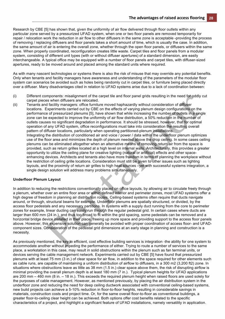
The advantages of raised access flooring 28
Research by CBE [5] has shown that, given the uniformity of air flow delivered through floor outlets within any particular zone served by a pressurized UFAD system, when one or two floor panels are removed temporarily for repair / relocation work the reduction in air flow to other diffusers in the same zone is acceptable -providing the process of removing / replacing diffusers and floor panels takes a short amount of time, which is usually the case. In addition, the same amount of air is entering the overall zone, whether through the open floor panels, or diffusers within the same zone. When properly coordinated, reconfiguration creates little waste. Carpet tiles and floor panels from a modular system, consisting of different unit types (with or without diffuser apertures) of a standard dimension, are easily interchangeable. A typical office may be equipped with a number of floor panels and carpet tiles, with diffuser-sized apertures, ready to be moved around and placed among the standard units where required.
As with many nascent technologies or systems there is also the risk of misuse that may override any potential benefits. Only when tenants and facility managers have awareness and understanding of the parameters of the modular floor system can scenarios be avoided such as holes being randomly cut in carpet tiles, or furniture being placed directly over a diffuser. Many disadvantages cited in relation to UFAD systems arise due to a lack of coordination between:
(i) Different components: misalignment of the carpet tile and floor panel grids resulting in the need for oddly cut carpet pieces when diffusers are relocated.
(ii) Tenants and facility managers: office furniture moved haphazardly without consideration of diffuser locations. Experiments carried out by CBE on the effects of varying plenum design configurations on the performance of pressurized plenums [5], have shown that while increasing the number of outlets in a single zone can be expected to improve the uniformity of air flow distribution, a 50% reduction in the number of outlets causes no significant degradation in performance. It should be stressed, however, that for optimal operation of any UFAD system, office reconfigurations must take into consideration the resulting overall pattern of diffuser locations, particularly when operating partitioned-plenum installations. Integrating the distribution of conditioned air and voice / power / data within the underfloor plenum optimizes use of the floor area and minimizes the depth of plenum needed above the drop ceiling. In some cases ceiling plenums can be eliminated altogether when an alternative means of removing return air from the space is provided, such as return grilles located at a high level on internal walls. Architecturally, this provides a greater opportunity to utilize the ceiling plane for creative lighting (natural or artificial) effects and other space-enhancing devices. Architects and tenants also have more freedom in terms of planning the workplace without the restriction of ceiling grille locations. Consideration must still be given to other issues such as lighting layouts, and the proximity of return air grilles to high heat sources –yet with successful systems integration, a single design solution will address many problems simultaneously.
Underfloor Plenum Layout
In addition to reducing the restrictions conventionally placed on office layouts, by allowing air to circulate freely through a plenum, whether over an entire floor area or within defined interior and perimeter zones, most UFAD systems offer a high degree of freedom in planning air distribution routes. Ceiling-based systems often require that ducts navigate around, or through, structural beams for example. Underfloor plenums are spatially structured, or divided, by the access floor pedestals and any necessary partitions. In systems with a supply duct running from the core to perimeter zones for example, linear ducting can easily run through the regular pedestal grid. In certain cases where ducts are larger than 600 mm (24 in.), and thus too broad to fit within the grid spacing, some pedestals can be removed and a horizontal bridge device installed in their place, freeing up more space and providing support to the access floor panels above. However, this expensive solution can generally be avoided with proper coordination of access floor- and UFAD-component sizes. Consideration of the pedestal grid dimensions at an early stage in planning and construction is a necessity.
As previously mentioned, the key to efficient, cost effective building services is integration -the ability for one system to accommodate another without impeding the performance of either. Trying to route a number of services to the same place, a workstation in this case, may result in solid obstructions within the plenum such as fan terminal units, or devices serving the cable management network. Experiments carried out by CBE [5] have found that pressurized plenums with at least 75 mm (3 in.) of clear space for air flow, in addition to the space required for other elements such as cable runs, are capable of maintaining a uniform distribution of airflow to diffusers, in a 300 m2 (3,200 ft2) zone. In situations where obstructions leave as little as 38 mm (1.5 in.) clear space above them, the risk of disrupting airflow is minimal providing the overall plenum depth is at least 180 mm (7 in.). Typical plenum heights for UFAD applications are 200 mm – 460 mm (8 in. – 18 in.). This exceeds the required plenum height when raised floors are used solely for the purposes of cable management. However, as mentioned previously, by placing the air distribution system in the underfloor zone and reducing the need for deep ceiling ductwork associated with conventional ceiling-based systems, new build projects can achieve a 5-10% reduction in floor-to-floor heights, resulting in considerable savings in materials, construction costs and project time. Or, for the same overall floor-to-floor as conventional buildings, a greater floor-to-ceiling clear height can be achieved. Both options offer cost benefits related to the specific characteristics of a project, and highlight a significant feature of UFAD installations, namely versatility in application.

The advantages of raised access flooring 29
Modular Components
Many of the advantages of both raised floors and, by extension, UFAD arise from the characteristics of the modular components involved. From pedestal spacing to carpet tile sizes, coordination between the various parameters is less complicated when design decisions are made with respect to the various modular dimensions involved, particularly when these dimensions are equal to, or multiples of, each other. In buildings with orthogonal floor plans this task is straightforward, non-orthogonal plans may require a number of custom sized panels or tiles at certain locations. Modular systems have the greatest potential for facilitating quick modifications within an office environment. These modifications typically fall into the following categories:
1. Spatial Configuration Changes in office hierarchy, layout or number of personnel may necessitate a rearrangement of workstations. Responding to new layouts of furniture simply requires substituting one type of floor panel (with floor diffuser/cable outlet) for another (without), as all panels will be of the same modular dimensions. Provisions should then be made for connecting into the nearest run of cables if the panel in question contains an information outlet. In plenums with fan terminal units the zoning layout should be consulted in order to maintain an even distribution of diffusers within that particular zone.
2. Load Distribution The addition of equipment or an increase in occupancy -both of which constitute heat sources- within any defined office zone will increase the demand for cooling in the proximity and may require additional floor diffusers. To increase the amount of air delivered to that zone standard floor panels could be replaced by diffuser-equipped panels placed in suitable locations (i.e. at an acceptable distance from occupants and unobstructed by furniture). UFAD systems employing fan terminal units may require minor adjustments to maintain a minimum airflow rate to all diffusers. Facility managers may wish to stock a surplus number of carpet tiles that are pre-cut with diffuser apertures for the purpose of meeting future reconfigurations involving an expansion in the total number of outlets required in the office space.
3. Occupant Preference The ability to accommodate varying occupant preferences is a key characteristic of UFAD systems. In addition to the option of adjusting the airflow rate, a person may request that a diffuser be located closer to/farther from their workstation locale. As described above for spatial configuration changes, this procedure involves removing the carpet tiles and floor panel at the location in question, and replacing them with an alternative panel and tiles. For example, if an occupant requests that a diffuser be moved closer to their workstation, a standard panel is removed and replaced by a panel fitted with a diffuser aperture. Once the diffuser components are installed, a carpet tile, cut according to the location of the diffuser, is placed as the finished floor surface and surrounding tiles are reaffixed. Consideration may need to be given to the location of plenum partitions, VAV boxes and the overall distribution of diffusers within a particular zone. When carpet tiles form the finished floor surface of a raised access floor system the issue of coordinating the modular sizes and grid dimensions of floor panels and carpet tiles must be addressed. Some manufacturers provide a composite unit of floor panel-plus-carpet tile so architects need only work with one modular dimension, as pedestal spacing is a function of the floor panel size. As components can be ordered on a supply-on-demand basis this potentially reduces material waste. When additional diffusers need to be installed, floor-and-panel composites can be ordered instead of necessitating the cutting of holes in existing carpet tiles that may later become redundant when, say, following a future reconfiguration new diffuser locations do not match those of the present. However, the majority of UFAD installations comprise floor panel and carpet components from separate manufacturers. As floor panels are typically 600 mm (24 in.) and carpet tiles 450 mm (18 in.) or 900 mm (36 in.), this raises the question of whether carpet joints and floor panel joints should align where possible, or be consistently staggered. Differences in opinion exist, yet many UFAD system installers recommend staggering joints between the two surfaces to avoid problems with uplift.
Summary
In summary, raised floors offer a cost-effective means of addressing the key factors characterizing 21st century workplaces, namely the need for an infrastructure flexible enough to meet high churn rates in our multi-tenant, multi-technology environments where the pace of future expansion is guaranteed, yet the nature of the expansion unpredictable. When properly coordinated and factored into decisions at the design, construction and occupancy stages, integrating cable management and air distribution services within the plenum of a raised access floor can increase the potential versatility of a workplace; and the ability to quickly meet occupant preferences contributes to a more dynamic work environment at all levels.

The advantages of raised access flooring 30
Appendix
Summarized below are a number of options for power and communications distribution in both new-build and retrofit projects. Often a combination of methods forms the overall cable management system in order to overcome the particular limitations of each.
Raised Floor Systems
The most flexible and versatile option in terms of unrestricted routing, potential for reconfiguration and ease of accessibility. Cables are run freely through the plenum created between a structural slab and raised access floor installation. Each workstation can connect into the cable network either via outlet boxes flush-mounted into floor panels, or openings provided in selected floor panels that enable cables to extend up to outlets integrated within modular furniture systems. Raised access floor systems accommodating modular cabling networks are the best example of a cabling innovation with the ability to support the multi-vendor, multi-technology infrastructure demanded by present day workplace environments. See modular cabling for more information. Consideration should be given to the structural, spatial, and visual impact of any cable distribution option. Factors influencing one of these parameters will undoubtedly have consequences for the others.
Loose Cabling
Cables (copper/fiber optic) are routed to workstations through wall and ceiling cavities. Although the least expensive option on a first cost basis, changing cable routes, increasing the number of cables, or carrying out maintenance work is disruptive both to the building’s structure and occupants. In the event of a faulty connection or cable breakage, tracing cables along their route can be difficult due to their concealment within the building’s cavities. This problem is compounded by the high risk of physical damage to the unsupported cables that must run around structural members and sharp corners, resulting in poor data transmission performance. In retrofit projects where there is a lack of space for accommodating the components of ceiling- or floor-based ducting, loose cabling may be a feasible option, providing the structural intrusion of routing through cavities can be minimized.
Cable Trays
A commonly used system whereby cable trays installed in the ceiling plenum are used to distribute cabling from telecommunications closets to workstations throughout an office floor or zone. At required locations a vertical conduit brings cables from the trays down to workstation outlet boxes. When properly designed, in terms of routing and sizing, cable trays can accommodate potential re-routing and upgrading, and their location above a removable-tile drop ceiling system facilitates access for maintenance. Disadvantages include the need to accommodate vertical conduits at workstations, and the need for a clear space of 200-300 mm (8-12 in.) above the ceiling plane.
Surface Raceways
As an alternative to concealing cabling in the ceiling / underfloor plenum, surface raceways are conduits installed around the perimeter of defined workspaces; affixed to a building’s external or internal walls for example. Although the cabling, and associated components, within raceways are accessible, and relatively inexpensive to install, routing options are limited to the location of walls. Workstations at a distance from the perimeter zone must rely on an alternative means of distribution to be connected to the cable network. Some modular furniture systems incorporate provisions for integrating cables within their partitions or desk units for example. Consideration should also be given to minimizing the visual and spatial impact of the raceways.
Poke-Through
In this system, cabling serving a particular floor runs within the ceiling plenum of the floor below. Where required, penetrations are made through the structural slab enabling the cables to enter the workspace for connections. Due to the significant structural implications associated with drilling through the floor slab, and the disruption caused to occupants of the floor below when accessing the cabling (implying this system is not so feasible for multi-tenant buildings), reconfiguration can be costly and complicated. When locating points of penetration, consideration must also be given to maintaining the structural integrity of the slab.

The advantages of raised access flooring 31
Modular Cabling
Described as a multi-vendor, multi-technology infrastructure, modular cabling installations can accommodate multiple cable systems comprising different media –voice, power and data- and originating from different manufacturers. The result is, effectively, a platform, or framework, upon which the building’s technological infrastructure is formed. Typical installations comprise three basic cabling components: riser cabling, workstation cabling, and, in a campus environment, outside plant cabling; and are subject to industry standards regulating performance- and physical-characteristics. For example, distinguishing between these three cable routes, and types, enables the infrastructure system to comply with standard ANSI/EIA/TIA-568-A Commercial Building Telecommunications Wiring Standard, which restricts the distance between active equipment (PCs and network equipment, for example) to a maximum of 90 m (295 ft) for copper cabling [6].
System Layout and Components
Network equipment is housed in telecommunications closets (TCs), which are distributed around a building according to the particular zoning or organization of the cable management system. A central TC is designated as the main distribution point, and is connected to all other secondary TCs by copper/fiber optic backbone cabling, also known as riser, or vertical, cabling. This results in a star-shaped, or ‘star-wired’, network with the central TC forming a nucleus from which backbone cabling radiates outwards. From each secondary TC, horizontal cabling transmits information to and from information outlets, the points of communication for cabling in the proximity of each workstation. Patch cable assemblies –cables with connectors attaching equipment at workstations to information outlets- facilitate easy technological reconfigurations or equipment additions at a later stage. By linking each workstation back to a main distribution TC, all equipment located within the system is effectively interconnected, improving both communication between devices, and overall system management. In addition, each information outlet can be separately reconfigured from a central location, in terms of the media connections offered, without disrupting other outlets within the entire system. This reduces the downtime (time during which office functions may need to be suspended) typically experienced in offices at great expense. The key to an effective modular cabling system is the implementation of a good cable management strategy. At this stage, once the cable wiring structure has been defined –location of main distribution points, TCs and cable routes- the specific requirements tenants will place on the user systems should be identified. All cables are categorized relative to their cable bandwidth per distance, a measure of how much information a particular cable can carry. For example category 3, sufficient for voice-grade applications, has the capacity of a bandwidth up to 16 MHz; category 5 is the most common (bandwidths up to 100 MHz) or 5E, a non-standard category, is used for bandwidths up to 200 MHz and distances over 100 m (328 ft). To maintain the level of communications performance specified by the cables, cable connections and terminating devices should have an equivalent rating. ANSI/EIA/TIA (the bodies regulating commercial building telecommunications) require that each workstation be supplied with at least two telecommunications cables, whose specific categories are also regulated by standards. In this way every workstation will support the most fundamental and commonly used telecommunications applications -such as voice and data for example.
Systems Integration
Integration is a means of optimizing overall building performance by monitoring and controlling a range of building systems and functions that effectively communicate with each other to ensure a high level of operational quality and efficiency. For example, a security system may be linked to: a time-of-day schedule, to allow entry at specific times the building maintenance system (BMS), to turn on the HVAC once occupants have arrived electronic building usage records, for monitoring tenancy/occupancy. There are many different modes of systems integration, the fundamental requirement being the ability to establish communications between the different devices and controls comprising a building’s services. This communication can be set up in a number of ways, for example: Control devices transmitting data electronically within their system. Control devices transmitting data electronically to other systems within the building. Hard-wired connections, a very common method of linking data from different building systems within a central BMS. Building systems operating independently but communicating electronically with a common BMS. This is a popular option in today’s buildings following the introduction of BMS-software packages. Building systems electronically communicating information to the entire controls network, exemplifying the highest level of ‘integration’. This option developed following networking innovations in the building industry, and offers the greatest potential for future expansion. Benefits One of the key components of an effective BMS is that of building operation monitoring. The benefits of implementing an integrated building system are immediately quantifiable:
Single, user-friendly interface.
Any number of systems within the BMS network can be accessed via a single interface. Simplifying the time and level of expertise needed to operate the network can result in increased productivity and reduced training costs.

The advantages of raised access flooring 32
Centralized monitoring.
Centralizing the controls and operational information of the many systems comprising the BMS enables comprehensive monitoring, and analysis at the general level of energy usage and/or, more specifically, parameters such as operational temperatures, for example.
Lower maintenance and repair costs.
System-wide monitoring enables breakdowns and operational faults to be quickly identified, and diagnosed, reducing office downtime due to failure of any particular system. A recent survey among members of the building industry showed 75% of building owners had impending projects incorporating systems integration [4]. In addition, an integrated BMS brings many qualitative benefits to the workplace, such as:
• Improved BMS monitoring. • Reducing both major system breakdowns and periods during which the workplace experiences sub-standard
operation of various building services. • Centralized and coordinated programming. • Synchronizing the operation and control of different systems for maximum effect with minimum effort -for example,
time of day-based lighting and HVAC schedules. All of the above, both qualitative and quantitative, contribute to improving the satisfaction and comfort of both occupants and owners. References [1] Piper, J., P.E., PhD. 1999. “Winning the information race.” Building Operating Management Online. [2] Germershausen, M. 2000. “Wired for success.” Buildings vol. 94, No. 7, July pp. 53-58. [3] Loftness, V., and P. Matthew. 1999. “Sustainable development alternatives for speculative office buildings: A case study of the soffer tech office building”. Center for Building Performance and Diagnostics, Carnegie Mellon University, Pittsburgh, PA. [4] BOMA International Foundation, 2000. “Integrated systems: Increasing building and workplace performance.” Buildings vol.94, NO. 4, April. [5] Bauman, F., P. Pecora, and T. Webster. 1999. “How low can you go?” Air flow performance of low-height underfloor plenums. Center for the Built Environment, University of California, Berkeley CA. [6] Viszoki, J.S., 1998."Designinga path to the future. "Building Operating Management Online. The standard referred to is ANSI/EIA/TIA-568-A Commercial Building Telecommunications Wiring Standard.