advantages of decorrugation of aeromagnetic data using … · advantages of decorrugation of...
TRANSCRIPT
1
Advantages of Decorrugation of Aeromagnetic Data using the Naudy-Fuller Space Domain Filter
Saad Mogren King Saud University, College of Sciences, Geology & Geophysics Department, Riyadh, Saudi Arabia ([email protected]) and J. Derek Fairhead GETECH, School of Earth and Environment, University of Leeds, Leeds, LS2 9JT, England ([email protected])
Abstract. Microlevelling or decorrugation methods used to remove line-to-line leveling errors of aeromagnetic data which are visible as linear anomalies parallel to the flight lines are explained in this study showing the advantages of using the Naudy-Fuller space domain filter. In this study three methods of microlevelling were tested, the first is microlevelling using Bi-directional line gridding, the second using FFT frequency domain procedures which is based on a directional cosine filter and Butterworth filters, and the third, and most preferable by the authors, is a combination of Naudy non-linear filter and the Fuller Hanned band pass convolution filter, that works in the space domain. Keywords:, Microlevelling, Decorrugation, aeromagnetic, Naudy-Fuller filter 1 Introduction Corrugation is a low amplitude element of flight line noise still remaining in the aeromagnetic survey data after tie line leveling. These residual errors show significant streaking or corrugations when the grid is visualized using shaded relief methods. If uncorrected then the computation of derivatives becomes dominated by these line-orientated noise effects. Therefore the gridded dataset should be filtered to reduce or remove non-geological effects caused by long-wavelength noise along survey lines. Some sources of corrugations are not very clear, however, in this case study the most important source of errors in the aeromagnetic data is due to line to line differences in flying heights. Another source of error arises from; inaccuracy in the measured positions of crossover points of acquisition and tie lines. If an error arises here, it may introduce an error covering a region that extends one line spacing in each direction. The dimensions of this region would therefore be twice the tie line separation by twice the acquisition line separation. A further error could arise from inadequate compensation for the magnetic field resulting from the aircraft.
43°45’
43°45’
43°30’
43°30’
43°15’
43°15’
23°30’ 23°30’
23°15’ 23°15’
23°0’ 23°0’0 10 20
Kilometres
MetreHigh : 1319
Low : 830
Flightlines
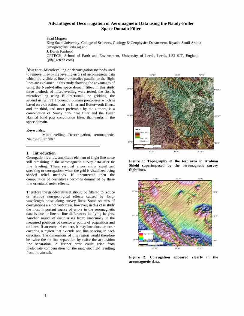
Figure 1: Topography of the test area in Arabian Shield superimposed by the aeromagnetic survey flightlines.
43°45’
43°45’
43°30’
43°30’
43°15’
43°15’
23°30’ 23°30’
23°15’ 23°15’
23°0’ 23°0’0 10 20
Kilometres
nTHigh : 427.383
Low : -898.339
Figure 2: Corrugation appeared clearly in the aeromagnetic data.

2
Corrugation also occurs if the (time-varying) diurnal fluctuations are not accurately measured at the base station, thus affecting part of the measurements along an acquisition line. Finally, corrugation can occur when adjacent flight lines are in opposite flight directions. Although the contractor performed standard compensation and diurnal corrections and leveling, the rugged terrain and widely spaced tie lines prevented complete removal of flight line noise as seen in (Figure 2). 2 Tested Microlevelling Methods In this study three methods of microlevelling were tested, the first is microlevelling using Bi-directional line gridding, the second using FFT frequency domain procedures which is based on a directional cosine filter and Butterworth filters, and the third, and most preferable by the author, is a combination of Naudy non-linear filter and the Fuller hanned band pass convolution filter, that works in the space domain and is implemented by the Intrepid™ software. These three methods of decorrugation are described briefly in the following sections.
2.1 Microlevelling using Bi-directional line Gridding
There are many methods for microlevelling of dataset collected along survey lines, and the success of any method is largely data-dependant. Microlevelling using the Bi-directional line Gridding, can be applied to gridded dataset alone, however for optimum results it should be applied to the original line data. In brief, the procedure involves a grid of leveling errors derived from a magnetic grid. These data are then subtracted from the original line data if available, or from the grid. The Bi-directional microlevelling method obtains the error grid by assuming that the gridded data consist of geology, a regional field, and leveling errors, these are separated out at various stages by low pass filtering during the gridding process.
43°45’
43°45’
43°30’
43°30’
43°15’
43°15’
23°30’ 23°30’
23°15’ 23°15’
23°0’ 23°0’0 10 20
Kilometres
Figure 3: Decorrugation using Bi-Directional Gridding. Leveling using Bi-directional line gridding involves rotating the aeromagnetic survey lines to E-W or N-S directions. For aeromagnetic data of this study,
decorrugation by Bi-directional line gridding did not show perfect results (Figure 3) probably due to the specification of aeromagnetic surveys as it was mentioned previously that decorrugation is largely data dependent.
2.2 FFT Decorrugation
Basically this method is a Fast Fourier Transform technique employing a high-pass Butterworth filter in conjunction with a directional cosine filter in the frequency domain. The technique can retain anomalies, from gridded data, in the flight line direction only. These anomalies are further filtered to remove geologically significant signal and to generate a correction grid. The corrections are subtracted from the original data. However, in this method it is difficult to distinguish between leveling errors and true geological anomalies of similar wavelength parallel to the flight lines. Therefore, the amount of corrugations removed were kept to a minimum by setting the Butterworth filter to four times the line spacing so that only frequencies on the order of the flight line spacing can be passed, and the directional cosine filter to pass wavelength only in the direction of the flight lines.
43°45’
43°45’
43°30’
43°30’
43°15’
43°15’
23°30’ 23°30’
23°15’ 23°15’
23°0’ 23°0’0 10 20
Kilometres
Figure 4: FFT Decorrugation. FFT decorrugation can be applied to gridded data but as for any decorrugation method, the best results are achieved by applying the resultant correction on the flight line database after removing any geological anomalies from the errors. This method demonstrates a reasonable outcome (Figure 4), although in some areas there were some remaining obvious corrugations.
2.3 Decorrugation by Naudy-Fuller filters
After removing the noise and spikes from the flight line data and gridding the test area (with rotating the flight line if they are oblique in direction to E-W or N-

3
S directions), an input grid for the decorrugation tools is produced. Grid were decorrugated using Intrepid™ Decorrugation tools, which were designed to remove anomalies (in these case errors) with precisely defined characteristics, and to specify corrections for corrugation. These correction do not remove geophysical information related to the geology since they extract residual errors with: the longest possible wavelength along the flight lines, the shortest wavelength perpendicular to the lines and the smallest dynamic range.
43°45’
43°45’
43°30’
43°30’
43°15’
43°15’
23°30’ 23°30’
23°15’ 23°15’
23°0’ 23°0’0 10 20
Kilometres
Figure 5: Decorrugation using Naudy-Fuller filters. In this study, the filter parameters applied a width twice the flight line spacing and length of at least twice the tie line spacing. However due to the nature of some of the aeromagnetic surveys data sets of this study the width had in some cases to be increased but not to exceed 25 % of the suggested length. The theory behind the above filter parameters is that a corrugation caused by differences between acquisition lines should have a wavelength of twice the acquisition line spacing. Corrugations can also be caused by errors in tie line leveling. If crossover points between tie line and acquisition line have errors then the total extent of the corrugation may extend as far as the next tie line on each side. Thus, the corrugation must have a length (wavelength) of at least twice the tie line spacing. This decorrugation method utilizes two types of filter: a high pass and low pass filters. The high pass filter is applied perpendicular to the acquisition lines direction, whereas the low pass filter is applied in the acquisition line direction. The aeromagnetic data have been decorrugated by applying the Naudy filter (Dreyer and Naudy, 1968) first followed by a Fuller filter (Fraser et al., 1966) for the high pass filter, and smoothed Fuller for the low pass filter as it will remove any introduced high frequency noise. Decorrugation by this method (Figure 5) removes almost all corrugations and produces well leveled grids.
3 Closer inspection of the methods. First vertical derivative (FVD) was applied on the decorrugated gridded data as seen in Figures 6-8 for closer inspection, which confirms that the best results were obtained by using a combination of Naudy and Fuller filters (Figure 8). This method removed (minimized) almost all the corrugation errors, whilst retaining the geological induced magnetic anomalies allowing the maximum resolution of the data to be retained.
43°45'
43°45'
43°30'
43°30'
43°15'
43°15'
23°30' 23°30'
23°15' 23°15'
23°0' 23°0'0 10 20
Kilometres
Figure 6: FVD of the Bi-directional decorrugation.
43°45’
43°45’
43°30’
43°30’
43°15’
43°15’
23°30’ 23°30’
23°15’ 23°15’
23°0’ 23°0’0 10 20
Kilometres
Figure 7: FVD of the FFT decorrugation.

4
43°45’
43°45’
43°30’
43°30’
43°15’
43°15’
23°30’ 23°30’
23°15’ 23°15’
23°0’ 23°0’0 10 20
Kilometres
Figure 8: FVD of the Naudy-Fuller decorrugation.