advantages and problems
TRANSCRIPT

The Advantages and Problems of
Torque Converters
as Used on Logging Equipment
on the Pacific Coast
by
J. David Waterhouse
A Thesis
Presented to the Faculty
of the
School of Forestry
Oregon State College
In Partial Fulfillment
of the Reg'uirements for the Degree
Bachelor of Science
May 1942
approved:
Professtr ofLoggIng Engineer

TÎBLE OF CONIENTS
Introduction . . . . . . . . . . . . . . . . . . i
Part I . . . . . . . . . . . . . . . . . . . . . 4
Iuustrations for Torque CLnverters . . . 14
Part II . . . . . . . . . . . . . . . . . . i7
Lo g LOcd e r s ,
Yarding Meckunes . . . . . . , . . . . . . 18
Conciusion . ,.... . . . . . . . 21
iterture Citea . . . . . . . . . . . . . . .
Tab les
rp T . . . . . . . . . . . . . . . . . ........
Tdbie II . . . . . . . . . . . . . . . . . 19

:1-.
INTRODUCTION
With ali its inherent advantages and economies, mech-
anicai engineers are usuaLLy willing to admit that the inter-
na! combustion engine lacks the smooth flexibility and high
starting torque of the steam engine. This is due to the diff-
erent torque characteristics of the two prime iovers, easy
to understand when one remembers that the impulses driving
the craxushaft of the internal combustion engine corne from a
series of explosions rather than from the application of a
vapor and a relatively constant pressure as in the case of
steam. Thus, the internal combustion engine relies upon
speed for the development of power and the overlapping of
the rapid explosions for smooth performance. To compensate
for its lack of lugging ability as increasing loads are im-
posed, the internal combustion engine requires a selective
transission between the crankshaft and final drive.
For years mechanical engineers have sought to provide
an intermediary device that would enable the internal com-
bustion engine to approach the torque characteristics of the
steam engine. The ideal device must be simple; it must work
without selection; and it must deliver rapid, smooth accel-
eration.
In attempting the solution, a great number of different
transmissions have been developed with varying degrees of
success. Many of them involve some ap.iication of air or oil
controls. Few,if any, have succeeded in overcoming all the
disadvantages coimìcn to these types of power transmission.
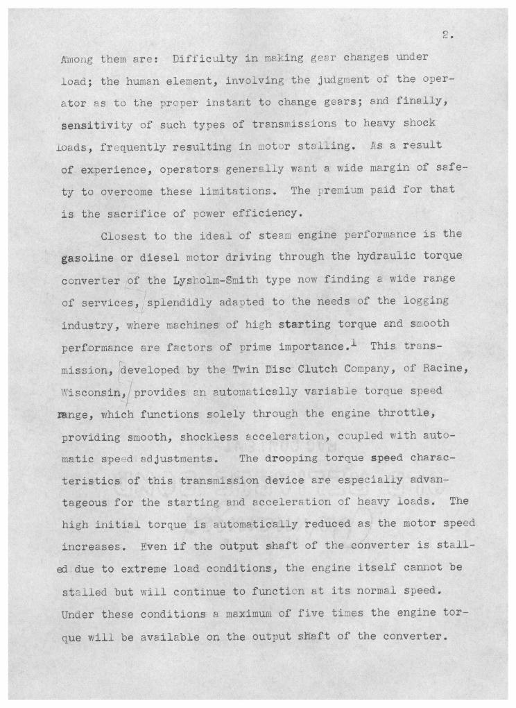
Ämoiig them are: Difficulty in making gear changes under
load; the human element, involving the judgment of the oper-
ator as to the proper instant to change gears; and finally,
sensitivity of such types of transmissions to heavy shock
..Loads, frequently resulting in iotor stiling. As a result
of experience, operators generally want a wide margin of safe-
ty to overcome these limitations. The .remium paid for that
is the sacrifice of power efficiency.
Closest to the ideal of stea engine performance is the
gasoline or diesel motor driving through the hydraulic torque
converter of the Lyshoim-Smith type now finding a wide range
of services, splendidly adapted to the needs of the logging
industry, where machines of high starting torque and smooth
performance are factors of prime importance.1 This trans-
mission, developed by the Twin Disc Clutch Company, of Racine,
',isconsin, provides rì automatically variable torque speed
mnge, which functions solely through the engine throttle,
providing smooth, shockless acceleration, coupled with auto-
matic speed adjustments. The drooping torque speed charac-
teristics of this transmission device are especially advan-
tageous for the starting and acceleration of heavy loads. The
high initial torque is automatically reduced as the motor speed
increases. Even if the output shaft of the converter is stall-
e1 due to extreme load conditions, the engine itself cannot be
stalled but will continue to function at its normal speed.
Under these conditions a maximum of five tLes the engine tor-
que will be available on the output shaft of the converter.

'7
Iiportrìt advant.es accruing to users ol' torque con-
verters cannot fail to impress orerators of logging machinery,
whose equipment is constantly subjected to shock loads and
variable speeds. The device is especisi-Ly desirable on yard-
ers and skidders, where evexy turn of logs nresents a differ-
ent problem in weight snd starUng torque. Pnother desirable
feature of the torque converter on the yarder is the fact
that high speed is available autoLaticaliy on the hauiback.
The torque converter works extremely well on loaders where
the operator can raise and lower his load by merely opening
and closing the throttle. Other logical applications would
£ncude draglines, locomotive cranes, etc. Equipment on which torcue c;nverters are instlied will
operate at a higher power factor, because the engixe speed
ratio is automatically adjusted to the work to be done, speed-
Ing up and slowing down as load conditions demand. Such en-
gifles in logging service, for example, will unquestionably
run longer without expensive overhauls and definitely excel
i_n the quantity of logs produced.
This introduction intends to give a brief summary of
torque converters and their apT'ication to logging equip-
ment.
The ¡nain part of this thesis which follows is an ex-
planation of the principles of torque converters together
with their application in the field with the benefits and
disadvantages listed. The largest part of this information was obtained from

4.
the Twin Disc C-iutch Cbrnpany and sorne of the equipment manu-
facturers who use torque converters on their products. Mr.
N. I. Matson, District Manager for the Twin Disc Clutch Com-
pany, and Mr. Dön McNeil, Chief Engineer for the V.iUamette
Hyster Company, supiied most of the material here assembled,
as well as helping with interviews and letters on the subject.
Part I
PRINCiPLES AND DESIGN F TORQUE CONVERTERS
Sèveral years ago, the Twin Disc Clutch Company. foresaw
the need for hydraulic drives in connection with iiitrnai corn-
bustion engines for oil field, railroad, logging and dirt moving machinery, and general industrial service, and immed-
iately began the development of both types: (1) The Hydrau-
lic Torque converter, under patents owned by Lyshoim-Sinith,
arid (2) The Hydraulic Clutch and Hydraulic Power Take-off.
As anticipated, the demand for hydraulic drives hs steadily increaed. This is conclusively shown by the pres-
ent widespreod use of Hydraulic Torque Converters and Hydrau-
lic Clutches in a wide variety of applications, ranging from
drilling rigs in the oli fields of Trinidad to loaders and
yarder in the logging camps of the Pacific Coast; in railcar and marine service, in locomotive and construction cranes,
and many others.
The process of. perfecting the hydraulic drives, like the development of any other essential piece of machinery,
was necessarily slow. The fie1 was new and comparatively

5.
undeveloped, and. there were few guiding precedents or estab-
lished practices to follow. Research and development were
further impeded by the fact that there was no test equipment
or laboratory facilities available to meet the needs imposed
by the job to be done. It was necessary, therefore, to dey-
eiop both the methods for testing and the ap:aratus with
which to make the tests, and to eqtup secial laboratories
for the necessary research, and to build up a personiel fam-
iliar with this type of work. Once these faci'ities were
provided, the many probLemns of production still remained to
be solved. Because each part was new to the production tine,
special machinery---dies, tools, guages, jigs, fixtures----had
to be designed to produce the various units in sufficient
nuribers to meet the anticipated demand, as well as to assure
ease of assembly, proper maintenance in the field, and the
complete interchangeability of parts.
All of these obstacles were ultimately hurdled, however,
and in December, 1938, the first of the Twin Disc Hydraulic
Drives, a torque converter, WE:S shipped to the oi± fields for
application to a cable tool drilling rig. The torque conver-
ter's advantages were soon recognized by the drilling industry
and, as additional units were shipped to this and other fields,
of industry, the desirability and superior performance of
hydraulic drives ws soon established.2
Before attempting to consider the design of the torque
converters or to compare the power and torque characteristics
of steam and internai combustion engines, it is necessary to
understand the relation of torque and speed to horsepower.

6.
Torque can be defined, briefly, as the effort producing
or attempting to produce, rotation or torsion. Torque may
be broken down into the product of two components.: (1) force
usually measured in pounds; and (2) lever arm distance, usu-
ally measured in feet. In other words, assume that a line
is pulled from a drum one foot in diameter by a force of 100
pounds. The force of 100 pounds is exerted at the end of a
lever arm of 0.5 feet (drum radius), thus producing a torque
of 100 x 0.5 or 50 ft. lbs. which is the effort tending to
rotate the drum.
P = loo LBS.
Torque = PxR
R =0.5 FT. I - lOOxO.5
Figure 1.
Further, assume that the above torque on the drum is
sufficient to rotate the drum (Figure i.) at a giveD number
of revolutions per minute. When torque is delivered at a
given r.te of speed, horsepower is developed arid, within
the elapsed time, work is accomplished. The relation of
horsepower to torque and speed is such that for a given aii-
ount of horsepower an increase in torque will be compensated
by a decrease in speed.
An automatically-variable, torque-speed type transmis-
sion will, without any help or guessvvork on the part of the


9.
Figure 3 shows the schematic diagram of fluid circu-
.Lation in the Hydraulic Torque Converter.
Then the reactionary blades are mounted in the station-
ary. housing and the housing assembled to the engine or to a
solid base, these blades cannot move when the fluid is forced
against them, so the fluid flov is re-directed aùd the fluid's
resistance to this change results in torque muitiplication.
Were it not for these stationary blades, there would be no
torque mdltiplication and the output torque would be equal
to that put into the unit by the engine. Due to the fact,
however, that the stationary blades, be re-directing the fluid
flow, do multiply the torque delivered by the motor, the unit
becomes a torque converter.
u,
Z4OC
u-
w 200C
o
600
200
801
40
'J
DO
lO
10
o o o o
n
200 400 600 800 1000 1200 OUTPUT RPM
Figure 4.
Before attempting a successful application of the Torque
cnverter, it is necessary to consider certain performance
characteristics which can be presented best in graphic form.
( Figure 4..) A tyical performance curve is shown above :?nd

10.
it applies to a stendard, plain Torque Converter. The curve
indicated output toraue obtained with an engine delivering
500 foot pounds of torque aL1800 RPM, which is the full
throttle speed of the engine. No prtia1 throttle charac-
teristics are shown. The top efficiency is a broad, practic-
ally fi&t curve with a peak of approximately 85 per cent. Ps
the output shaft speed approaches two-thirds of the engine's
spetd, the engine snd converter torques become equal.
Viewed solely from the theoretical standpoint, the Torque
Conveiter does not ap ear to be ss efficient a unit as it is
in actual operation.
To apireciate its tx'ue efficiency, in the full practi-
cal sense of the word, it is necessery to observe the Torque
Converter at work on the job, because its performance in the
field---the all-important factor to the operator---fQr out-
strips the performance indicated by the efficiency curve.
The Torque Converter's efficiency characteristic is not
the mostimportant considerafion in making an application.
It is far more important to analyze carefully the job the
converter is expected to do. Once this is done, and the con-
verter is then applied so that it will be able to do rost of
the work within its best operating range, maximum efficiency,
as interpreted in terms of work done, is assured. By taking
these precautionary steps, the efficiency and torque-speed
characteristics of the converter can be tailored to the work
requireiients of the job to be done.
Consider, for example, the case of a tractor equipped with

II.
s four speed transmission. The horsepower available in each
gear plotted against the respective speed in MPH is repre-
sented by curves in Figure 5. Even with the ablest operator
shifting gears at the most opportune times, it is evident
that the average work that can be performed. under varying
load conditions cannot exceed the shaded ares shown in Fig-
ure 5.
If a hydraulic transmission of the torque converter
type were applied, the horsepower available plotted against
the speed in MPH wouid result in the curves sbwn in Figure
HP
HP
FIG. 1 MPH
Figure 5
FIG. 2 MPH
Figure 6

At first g1nce, it appears that the lower peak efiic-
iency of the hydrauLic unit is overshadowed by a more favor-
able performance of the gear transmission. This coraparson
is incorrect because al four speeds of tbe transmission sre
being compared collectively.
In actual service, gear shifts usually cannot be made
without coming to a complete standstill; therefore, in order
to ueasure the ariount of work done, the conditions in each of
the four speeds must be compared separately vnith the corres-
ponding ccnditions prevailing in the hydraulic drive. Such a
campari..son is shown in Figure 7. This comparison brings out
clearly that the gear transmission permits the delivery of a
higher peak output in each speed. In actual operation, how-
ever, it is very seldom possible to make use of this pea.k
output becuse of the very narrow range of the peak during
which it is available in each case.
HP
FIG. 3 MPI-I
Figure 7
A thorough analysis of the conditions under which a trans-
ission-equipced unit is operated shows that the power factor

is generally betv.reen 50 and 60 per cent. In other words, it
is necessary to run at partial loads with the engine operating
against the governor in order to have a certain atouflt cf
power reserve available for contingent increaes of load.
A converter-equipped unit will be operatied of necessity
at "Unity Power Factor" because it will always operate at the
highest speed at which the load can be pulled, automatically
slowing down and speeding up as è1oad varies.
From the above analysis, it is evident that the Torque
Converter-equipped unit will produce slightly lower output
peaks, but at the end of a working period in actual service,
it will have excelled in the nount of work done.
An actual proof of the above statements is substantiated
by the test results tabulated below which were obtained with
a standard tractor and one of the same model equipped with a
Torque Converter operating under the same conditions.4
Table 1
Torque tandard Converter Per Cent Tractor Tractor Increase
'- 1,2 ::.Lu
ourly mileage fOr 2.85 3.95 equivalent loads. 3.52 4.95 40
4.40 5.35 22

14.
Illustrations of Torque Converters:
The Direct LriVe Converter (Figure e) . This type of
converter is intended for app1icìtions such s rail cars and
other sii1sr enuiprnent where the hydraulic drive is used dur-
Ing the acceleration period and the direct drive during the
normai full speed operation. With this combination it is
possible, by merely shifting the clutch, to provide for the
high starting torque developed in hydraulic drive and requir-
ed for ouick, smooth acceleration, and also to take advan-
tage of the dditional speed range arid rriximum efficiency
in direct drive for normal propulsion and high speed operation.
The Plain Converter (Figure 9). This type of converter
is intended for industrial installations where a continuous
hydraulic drive is desirable. The drooping torque charac-
teristics and automatic torque-speed adjustment render these
models particularly adaptable to any service where heavy loads
have to be continuously started and acceierated (hoists,
cranes, switching locomotives, oil field and logging equip-
ment, etc.).5

15.
Figure 8.
ectiona1 rawing of
Direct Drive Converter -- Model DF

NQORMO.O I
SA 4OUSIIG
EQUAlLY SPAtD
V - IS.7! l8.7O,
Ill 4
'+-*---- H-'---- ' -r- 8 - I. I Y--- OUTLINEOFCOOIINGWATEP. JAcKET WATEP OUTLET JACKET ASSEMBLY
.
l$TD. PIPE TAP Z MOLES I
SUPU!D AS OPTiosAL I
EQUIPMENT IF CPE(IPIEO ,
II INJECTOP. MIlI PROM
- I '---IS' JACKET WATER INLET
' ,- j - I STD. PIPE TAP REÇVE TANK
( r STO.PIPETAP
'.._._) :
OUTLET TOCOOLE -J USEDONLYON UNIT
WITMOUT WATER JACKET
r____________________ I" STD. PIPE TAP
I
- - -11F
00
ASPIRATOR CONNI
-9 STD. PIPE TAP
16.
't
3ó0o 2-999
b _ .
t ,. \\I
Figure 9.
Section1 Drawing of the
Plain Oonverter -- Model F

17.
Part II
APPICATIONS OF FYDRTLJIC TOR')UE CONVEPLTEHS
Due to the diesel engine's limited speed range, the prob-
iClu of providing e satisftctory operating speed range in in-
dustrial service s :nore acute than any previously encoun-
tered in gas or gasoline engine applications. Therefore, a
power transiiission that will permit
gifle at its normal and most efficie:
gardiess of the speed of the driven
tae and an asset which is nov' more
ever before.
It is a conceded fact that in
the operation of en en-
at operating range, re-
n&chiriery, is an advan-
commonly appreciated than
many types of irdstria1
installations, engines are being installed which are larger
than wouid nor1:eliy be required to carry the average operat-
Ing lo,d. This is done solely for the purpose of providing
a means to take c're of momentary overload conditions. How-
ever, by using a Torque Converter in connection with an in-
ternal combustion engine it is possible in most cases to use
a smaller engine operating at sorde what higher seeds to do
the saine work which normally wbuld require a larger, heavier,
sìow-sped enine.
In addition to new machinery equipped with the Torque
Converter, there is a tremendous field for Torque Converters
in machinery which has been designed for operation with steam
engines. For example, by providing an internal combustion
engine with the characteristics of a steam engine, direct
replacement of the steam engine can be accomplished without

la.
any major changes in the balance of the machinery.
Log Loaders:
In this type of application, the Torque Converter is
the sole power transmitting unit, supplying power to the
jackshaf t from which all operations originate.
Regardless of the size of the log, the machine will
handle it at the fastest speed possible. The operator has on..y
to open and close the throttle to raise and lower the load.
This ability to control the load with the throttle makes
good brakes less important and gives the loader ali the ad-
vantages of a steam loading machine.
Yarding Machines:
Appiied to this type of equipment, the Torque Converter
has rendered invaluable service or many of the Northwest's
logging operations, particularly where the yarding job is
complicated by excessive undergrowth, stunips, and other obsta-
eles. On shows of this type, operators have been quick to
recognize the converter' no-stall and shock-cushioning char-
acteristics as important factors in maintainin a high rate
of production and extending the life of allied equipment.
For example, on a British Columbia show where two twin
engine yarders, powered with identical engines, one using a
standard gear-type transmission, and the other equipped with
a Torque Converter, daily production figures showed an ad-
vantage of 17 to 20 per cent in favor of the converter- equip-
ped unit.
Jiother time study was recently made for purposes of

19.
caniparing a four-speed three-drum ysrder with a converter-
equipped yarder. The results of this study, an shown in
Table II below, reveal that besides the converter-yarder br-
ing in more logs in less time, the rig also showed a 58.5%
increase in line speed when yarding over a 30% greater dis-
tance.
Table II
4-Speed Transmission Yarder
Total Hang-up Dis- Log Size Time Time tance Rate No. (Feet) (Min.) (Min.) (Feet) (Ft./ixi.)
1 4,000 11 1/2 2 700 74 2 500 2 1/2 0 750 300 3 1,000 9 3/4 3 700 104 4 1,000 6 z/4 3 750 200 5 2,500 18 1/2 9 750 79 6 800 4 1/2 0 800 178 7 3,030 6 o 800 134 8 3,000 6 0 800 134 9 3,000 61/4 i 750 143
10 1,000 3 1/2 0 750 214 11 3,200 4 1/4 0 750 134 Total 23,000 79 1/2 18 8,300 1,694
Twin Disc Torgue Converter Equipped Yarder
1 1,575 5 1/2 0 900 163 2 2,250 5 0 900 180 3 3,400 8 0 900 U.3 4 1,000 2 1/2 0 900 360 5 2,000 4 1/2 0 900 200 6 3,000 6 0 900 150 7 1,000 3 0 900 300 8 1,800 4 3/4 0 900 190 9 2,000 II 1/2 5 900 139
10 1,000 2 1/4 0 900 400 II 1,500 3 3/4 1 900 327 12 2,000 5 1/2 0 900 164 Total 22,525 62 1/4 10,800 2,686
Percentage gained by Converter-Yarder 27.6 00 30 58.5

Aplied to twin engine ysrders, the Torque Converter
gives that added sdvantage of providing for proper distri-
bution of the load and preventing one engine from fighting
the other. Two-speed drums are sometimes used to increase the
operating range.
That the Torque Converter is firmly entrenched as esa-
ential equipment in the logging industry is plainly indic-
ated by the connents of both operstors and :nanufectures, three
of whom are quoted at random as follows:
?: British Columbia logger says, "This machine will pull as large a log out of a bd hole as she forerly wouid as a stear unit. lt.hen running in the haulback line and the straw- line, tachometer tests on the crankshaft showed that this machine is running 12 per cent faster on the light pulls than when she was a steam unit. e stalled the output shaft of the converter against s stump for a full minute. The engines v:ere then idled for thirty seconds and the stalling pull again exerted for a full minute. This operation was continued three tiLlies atid we found it as impossible to raise the tei- perature in the converter or engines over 160 degrees."6
A washington logger says, "In 36 days, averaging 70M a day, we wore out---didn't brEak---three cabie chokers, us- .ng a converter-equipoed gas yarder. With a geared trans- mission yarder, we would have broken at least a choker a day ---would have spent $1,170 for chokers against the 97.5O actually spent. Furthermore, e didn't lose any time for broken riggîng---all the crew's time was productive time."7
A yarder manufacturer says, "There seems to be an ever increasing appreciation of the value of the Torque Converter in the logging machinery field. Constant motor speed and freedom from gear changing give the Torque Converter all the advantages of steam with many added economies----ve see great possibilities for the Torque Converter in logging appli- cations.

C-
CONCLUS IOi'
Although, in the brief space of a few years, the use of
h;drauiic drives has effected startling improvements n uLany
dïffernt applications, it is conceded among the men who are
familiar with this new development in transmissions that the
gains aiready made are nothing as c;iu:aredwith those iii store
for the future. Tils generally-held belief is based on the fact that,
u ufltil the present tiie, hydruíc drves have been applied
almost exclusively on already existing equipment, as an after- thought. In st cases, they have been attached to a prime
mover---normally an internal combustion engine----which was
designed to accommodate an entirely different type of trans- mission. Due to this fact, it hs usually been necessary to
make coniproses md sacrifices which made it impossible to
obtain the best results and optimum perforrrnce characteris-
tics from the hydraulic units. A survey of the development work now going on among many
manufacturers, hovever, indicated that this period of make-
shift installations is nearing an end and that in the near
future, hydraulic drives will be given a real opportunity to
show what they csn do. Vith the new designs now on the draft- .- ing boards, taking into consideration the performance cilarac-
teristics of hydraulic drives, it will soon be possible to ut
matched units into the field; units vhich have b-:en designed
and engineered throughout to complement all the desirable
features of the other.

The future of hydraulic drives is further brightened by
the fact that the Twin Disc Ciutch Company's faciities for
research, desgn, and production are being constantly ihiproved
and exuarged as additional operating data from the field be-
comes avai.Lable.
In addition, both anufcturers of allied equipment and
the men who will operate that equiìment on the job are stead-
uy gaining a wider knov;iedge of the ooeraton and care of
hydraulic drives and this, too, wlil be a factor conducive
to improved performance.
In view of ali these fcts, it can be reasonably assumed
that hydraulic drives 7:jjj be the means of effecting greatly
improved performance of any machine or any job of which they
are a part, from the standpoint of more work done, at a
iöwer cost, in less time, with less wear and tear on the
equipment.

2.
Figure 10.
'ililarnetter Hyster three-drum yirder eouipped vith Twin Disc Hydraulic Torcue
Converter owned by C. D. Johnson at Toledo, Oregon.

Figure ii.
Close-up of Wi11amette. Ryster
three-druir yarder with Torque Convertr
Figure 12.
hydrauLic Power Take-off s insta iled
in a Lorin Shovel

Figure 13.
One of two Gunderson Brothers tvn ied
yrders built for the C. D. Ray oggirig Coiupany,
Fairview, Oregon. Units are powered ith GM Die-
sels equiti:ed vith Twin Disc Toroue Converters.
Figure 14.
Vashington Iron orks Loader
equiped with Twiri Disc Converter.
25.

26.
LITERATURE CITED
1. R. i. Schaffer, The Timberman, May 1940, Page 48.
2. Hydraulic Drives, 3. Twin Disc Clutch Company,
Racine, \isconsin.
4. The Story About Vork Done, Hydraulic Department, Twin Disc Clutch Company, Racine, Wisconsin.
5. Laintenance Uandbook--HydrauiC Torque Converters, Twin Disc Clutch Company, Racine, isconsin.
6. Hydraulic Drives, 7. Twin Disc Clutch Sompany, 8. Racine, ijSCOflSifl
Anyone desiring further ínforrnstion on this topic
will find M N. I. Matson, District Manager, Twin Disc
Clutch Company, 539 First Avenue, South, Seattle,
.ashington, very friendly and cooperative in supplying
ìnforLlat ion.