advances in crush analysis -...
TRANSCRIPT

Advances in crush analysis
Klaus-JuÈ rgen Bathea,*, Jan Walczakb, Olivier Guillerminb, Pavel A. Bouzinovb,Heng-Yee Chenc
aMassachusetts Institute of Technology, Mechanical Engineering Dept., Cambridge, MA 02139, USAbADINA R&D, Inc., 71 Elton Avenue, Watertown, MA 02472, USA
cFord Motor Company, 20000 Rotunda Drive, Dearborn, MI 48121, USA
Abstract
Advances in capabilities for the crush analysis of structures are presented. Such analyses are di�cult to performand require state-of-the-art analysis procedures: e�cient and reliable shell elements, an e�ective and general contactalgorithm, e�cient procedures to calculate the element stresses in elasto-plasticity, the use of consistent tangentmatrices, e�ective nonlinear incremental solution strategies and the e�cient solution of the algebraic ®nite element
equations. Moreover, the e�ectiveness of the complete analysis process can only be achieved by ensuring that eachof the above solution procedures is in an e�ective manner integrated into a complete solution scheme. This paperfocuses on the advances developed in ADINA and presents various analysis cases solved with the program. # 1999
Elsevier Science Ltd. All rights reserved.
1. Introduction
Nonlinear ®nite element analysis of structures, ¯uids
and ¯uid-structure interactions is conducted to an
increasing extent. While in certain areas nonlinear
analysis can now be performed in almost a routine
manner, in many other areas, the state-of-the-art is
continuously being advanced. One such area in which
recently signi®cant advances have taken place is the
crush analysis of structures.
An important application area of such analysis capa-
bilities is the crush analysis of motor car models.
While frequently the same analysis procedures are
used for a crush analysis as for a crash analysis, it is
important to recognize the fundamental di�erences in
the crash and crush phenomena. Crash analyses simu-
late fast phenomena requiring a transient analysis. For
example, in the crash analysis of a motor car, the
crashing of the car at about 30 mph into a rigid wall is
simulated. The main event takes place during a few
milliseconds. These analyses are generally conducted
using explicit analysis procedures with shell elements
and assumptions speci®cally developed for modeling
the transient solution. On the other hand, crush ana-
lyses simulate slow phenomena that are appropriately
analysed using static analysis procedures or implicit
dynamic techniques. For example, in the crush analysis
of a motor car, the purpose is to establish the ultimate
strength of the car body in a static situation. The ulti-
mate strength a�ects the behavior of the car in various
operating conditions, including when the car overturns
in an accident. The laboratory experiment to identify
the crush behavior is performed by crushing the car
slowly, at about 0.02 mph and for about 10±30 s using
a device to push a thick steel plate onto the car roof
and measuring the load-deformation relation.
Computers and Structures 72 (1999) 31±47
0045-7949/99/$ - see front matter # 1999 Elsevier Science Ltd. All rights reserved.
PII: S0045-7949(99 )00041-3
* Corresponding author. Tel.: +1-617-253-6645; fax: +1-
617-253-2275.

In general, a crush analysis is rather di�cult toachieve. The reasons for the di�culties lie in that a
slow speed almost static analysis requires particularrobustness and e�ciency of the solution algorithms.The shell elements must be of high predictive capa-
bility, be robust and computationally e�cient for largedeformation static analysis. The stress conditions mustbe evaluated e�ciently including the plasticity and rup-
ture conditions. The contact algorithm must allowthree-dimensional multiple body and self-body contacton the outer and inner surfaces of the car shell, be
robust and give fast convergence in the iterations forstatic equilibrium at the di�erent deformation states.Consistent tangent matrices must be formed for thelarge deformation elasto-plastic and contact con-
ditions, and the nonlinear incremental solution strategywith the solution of the algebraic ®nite elementequations must be e�ective [1].
Frequently, a crush analysis is performed using anexplicit crash analysis code, because the problem withthe strong nonlinearities cannot be solved with implicit
analysis options. However, such an analysis approachmay not be appropriate as was already discussed inRef. [2].
The objective of this paper is to summarize somethoughts regarding crush analysis and report on someanalysis procedures that can be employed e�ectivelyfor crush simulations. Since crash analysis codes are
frequently used for crush analysis, outlined in the nextsection are the di�culties that can arise in a crushsimulation when a crash analysis code is used. Section
3 then focuses on e�ective analysis procedures forcrush solutions with particular emphasis on the speci®crequirements for such analyses. This discussion is fol-
lowed in Section 4 by the presentation of some analysiscases. These analyses represent in many respects thecurrent state-of-the-art of the nonlinear analysis ofstructures. Finally, in Section 5, conclusions regarding
the current state of crush analysis and comments onfurther developments in the ®eld are presented.
2. Crush analysis with crash analysis programs
As was pointed out above, the basic physical di�er-ence between crash and crush conditions is that acrash event (taking a few milliseconds) requires a
dynamic solution, whereas a crush event (takingseconds) requires a static (or implicit dynamic)solution. However, the nonlinearities in a crush event
are very large and the static solution algorithms usedmust be particularly powerful. For this reason, fre-quently, an explicit dynamic solution is performed to
assess the crush behavior of the structure under con-sideration. The governing equations considered for atypical time step are then, using the central di�erence
method [1],
Mt ÈU � t Rÿ tF �1�
t ÈU � 1
�Dt�2 �t�DtUÿ 2tU� tÿDtU� �2�
DtRDtcr � 2
o n
�3�
where tR is the vector of externally applied nodalloads, tF is the vector of nodal point forces corre-sponding to the element stresses, M denotes the
lumped mass matrix, and tU, tUÈ are the vectors ofnodal point displacements and accelerations. Thesuperscripts (tÿDt, t, t+Dt ) denote the times con-
sidered. With the conditions known at times tÿDt andt, Eqs. (1) and (2) can directly be solved for the displa-cements at time t+Dt, and since M is a diagonal
matrix, the solution is very e�ective for each time step.Special equations are used involving the initial con-ditions to start the integration process. In Eqs. (1) and(2), velocity-dependent damping forces are neglected
and a constant time step size is assumed. These restric-tions can of course easily be removed [1].Eq. (3) expresses the fact that for a stable inte-
gration, the time step Dt must be smaller than the criti-cal time step Dtcr given by the largest frequency in themesh, on.
As seen in Eqs. (1) and (2), in the explicit time inte-gration solution, a sti�ness matrix is not formed, iter-ations for equilibrium at the time steps considered are
not carried out, and instead a simple time-marching-forward solution is produced. This analysis approachis attractive because di�culties with respect to conver-gence in equilibrium iterations do not arise.
This explicit analysis approach can be used, butrequires many time-marching steps, because the explicitsolution scheme is only conditionally stable: that is,
the time step used must be smaller than the criticalstep size Dtcr. Usually, in shell analyses, the criticaltime step size is of the order of a microsecond.
Therefore, millions of time steps must be carried outto obtain a physically correct solution. The compu-tational time for such a solution is very high, and waysto reduce the required number of time steps have been
sought. In one approach, the speed of the event isincreased, resulting in a smaller number of time stepsrequired for solution. In another, somewhat equivalent
approach, the density of the material is arti®ciallyincreased, resulting in a larger critical time step size,and hence also into a smaller number of required sol-
ution steps. Some success with these approaches hasbeen reported in metal-forming analysis, largelybecause the structures analysed are highly constrained
K.J. Bathe et al. / Computers and Structures 72 (1999) 31±4732

by displacement boundary conditions. However, in acrush analysis, the crushing device is typically applied
to a structure largely free from displacement con-straints, and then these approaches result in arti®cialinertia forces that can have a signi®cant e�ect on the
structural response and the crushing force. Of course,the magnitudes of the arti®cial inertia forces can bemeasured, which will give an indication of the error in
the solution. However, for this error to be acceptablysmall, in essence the actual physical conditions must beused. For an example analysis in which these solution
di�erences have been studied in detail, see Ref. [2].Of course, if the explicit solution is carried out at
the physical conditions of the problem (that is, with-out, for example, arti®cially increasing the speed of
crushing or the material density), it is also necessary touse solution algorithms that are stable and accurateduring the time integration [1]. Since the conditions
then correspond to a static analysis, the shell elements,contact algorithms and other procedures used in theexplicit dynamic solution must be applicable to these
analysis conditions (which is not necessarily the casewhen a crash analysis program is employed, seeSection 4.2).
Considering an implicit dynamic crush analysis,which reduces to an incremental static analysis if thetime steps are large, the following equations are solvedin a Newton±Raphson iteration for a typical time
t+Dt considered [1]
M t�Dt ÈU � t�Dt Rÿ t�DtF �4�
where the matrices and vectors are as de®ned belowEq. (3), but a consistent mass matrix is usually used
because more accurate results can then be expected.The Newton±Raphson iteration to solve Eq. (4) is, fori=1, 2, . . . , until convergence measures are satis®ed,
M t�Dt ÈU�i � � t�DtK�iÿ1�DU�i � � t�Dt Rÿ t�DtF�iÿ1� �5�
where
t�DtU�i � � t�Dt U�iÿ1� � DU�i � �6�
and the `initial conditions' correspond to the state cal-
culated for time t
t�DtU�0� � t U, t�DtF�0� � t F, t�DtK�0� � t K �7�
In Eq. (5), K is the tangent sti�ness matrix and theiteration counter is given by the superscript (i ). Eqs.
(4) and (5) are used with a time integration scheme(typically the trapezoidal rule is used), and the iter-ation is continued until convergence to a speci®ed tol-
erance is reached. Note that in Eqs. (4) and (5), thecontact conditions are not explicitly indicated. If apenalty-type procedure is used, the sti�ness matrix K
and force vector F are appropriately modi®ed, whereasif a Lagrange multiplier technique is employed, ad-
ditional (tangent matrix) equations are assembled andsolved [1].Considering the implicit solution approach, the
major computational di�erences to the explicitdynamic solution lie in that tangent sti�ness matricesare established, equilibrium iterations are performed
and, of course, much larger incremental load (or time)steps are used. Typically, for a crush analysis, about100±200 steps are only required. In addition, it is im-
portant to note that there is also signi®cantly morephysical insight that can be gained in the analysis.Namely, if an incremental static analysis is carried out,the solution indicates bifurcation points that in an
explicit dynamic solution are not detected, because nosti�ness matrix is calculated and the arti®cial inertiae�ects mask these physical instabilities. It can be im-
portant that such bifurcation points are detectedbecause they indicate that additional equilibriumpaths, beyond those calculated are actually possible. In
general, one of these additional equilibrium paths, andnot the path calculated, may actually be observed in aphysical experiment or in the ®eld.
3. On ®nite element procedures for crush analysis
As pointed out in the previous section, the ®nite el-ement procedures must be particularly robust and
e�ective for a crush analysis. The objective in this sec-tion is to give some thoughts to the techniques that areconsidered suitable for crush solutions.
3.1. Shell elements
An important ingredient of a ®nite element modelfor crush analysis is the shell element employed. Any
elements used must ful®ll the reliability and e�ective-ness criteria enumerated by the authors for some time[1±4]: the elements must not contain any spurious zero
energy modes, must not be based on arti®cial numeri-cal factors, must not lock in membrane and shearactions, should be applicable to general shell geome-tries, and ideally should display, independent of the
shell geometry, the optimal convergence rate consistentwith the interpolations used. The MITC shell elementsseem to represent the state-of-the-art according to
these criteria as evidenced in references [5] and [6]. Inparticular, the element formulations are not based onany numerical factors (as are used in stabilized ®nite
element formulations) and show good convergencebehavior for membrane and bending dominated pro-blems.
K.J. Bathe et al. / Computers and Structures 72 (1999) 31±47 33
The general applicability, reliability and e�ectivenessreferred to above are di�cult to achieve, but much
progress has been made through physical intuition,mathematical analysis and well-chosen numerical ex-periments. The mathematical model underlying the
general shell elements used in practice (which arebased on three-dimensional continuum mechanics the-ory degenerated to shell behavior), and the consider-
ations for stability, convergence and optimality of shellelements for general applications are discussed in Refs.[4±7].
A crucial part of the evaluation of shell elements isto solve judiciously chosen problems in a study of theconvergence behavior. Such problem solutions are pre-sented in Ref. [5], where it is shown that the MITC
shell elements perform well for the spectrum of typesof practical analyses encountered.
3.2. Large deformations and plasticity
The classical total and updated Lagrangian formu-lations are e�ective for the solution of very large defor-mations of solids and structures [1]. These
formulations have the advantage that they are totaland not rate-type formulations, which means that nointegration process is required in the kinematic updat-
ing process. The formulations are also e�cientlyemployed with a fully implicit scheme to calculate theplasticity variables, and the e�ective-stress-function
(ESF) algorithm to solve for the stresses is used [1,8±11]. The Lagrangian formulations with the elasto-plas-ticity ESF solution technique admit relatively large
incremental steps and consistent tangent matrices canbe evaluated [1].The details of the MITC shell element formulation
for large deformation analysis are given in Ref. [1]. A
key ingredient in the formulation is that nodal pointdirector vectors are used whose positions and direc-tions are updated in each incremental solution step.
This procedure allows for very large displacements androtations, in elastic and elasto-plastic conditions.Of particular signi®cance is that elements with spur-
ious zero energy modes (for example, due to reducedintegration) should not be used in practice. Anexample solution, in which due to reduced integration,element zero energy modes result in nonzero ghost fre-
quencies of the complete structure is presented in Ref.[1], p. 473.In elasto-plastic analysis, there is a tendency to use
simple reduced integration to relieve the lockingphenomenon due to the incompressibility constraint(and the locking phenomena due to arti®cial mem-
brane and shear stresses). Such reduced-integrated el-ements should be employed with great care because ofthe unphysical solutions that can be generated.
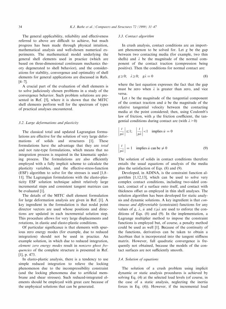
3.3. Contact algorithm
In crush analysis, contact conditions are an import-ant phenomenon to be solved for. Let g be the gapbetween two contacting media (for example, two thin
shells) and l be the magnitude of the normal com-ponent of the contact traction (compression beingpositive). Then the conditions for normal contact are:
gr0; lr0; gl � 0 �8�
where the last equation expresses the fact that the gapmust be zero when l is greater than zero, and vice
versa.Let t be the magnitude of the tangential component
of the contact traction and uÇ be the magnitude of the
relative tangential velocity between the contactingmedia at the point considered; then, using Coulomb'slaw of friction, with m the friction coe�cient, the tan-
gential conditions during contact are (with l>0)���� t
ml
����R1;
���� tml����<1 implies _u � 0
���� tml���� � 1 implies _u can be 6� 0 �9�
The solution of solids in contact conditions thereforeentails the usual equations of analysis of the mediaplus the satisfaction of Eqs. (8) and (9).
Developed, in ADINA, is the constraint function al-gorithm [1,12,13], which can be used to solve verycomplex contact conditions, including two-sided con-
tact, contact of a surface onto itself, and contact withthickness o�set as employed in thin shell analyses. Thesolution algorithm has been developed for static analy-sis and dynamic solutions. A key ingredient is that con-
tinuous and di�erentiable (constraint) functions for anyvalues of g, l, _u and t/ml are used to enforce the con-ditions of Eqs. (8) and (9). In the implementation, a
Lagrange multiplier method to impose the constraintfunctions is employed but, of course, a penalty methodcould be used as well [1]. Because of the continuity of
the functions, derivatives can be taken to obtain aJacobian that is incorporated into the tangent sti�nessmatrix. However, full quadratic convergence is fre-quently not obtained, because the models of the con-
tact surfaces are not su�ciently smooth.
3.4. Solution of equations
The solution of a crush problem using implicitdynamic or static analysis procedures is achieved by
solving Eq. (4) at the selected load levels (of course, inthe case of a static analysis, neglecting the inertiaforces in Eq. (4)). However, if the incremental load
K.J. Bathe et al. / Computers and Structures 72 (1999) 31±4734

level is too large, di�culties in the convergence of Eq.(5) are encountered. In this case, a solution strategy
must be employed that appropriately reduces and thenagain increases the incremental load level [1,8]. In theADINA program, a load-displacement-constraint
(LDC) procedure and an automatic-time-stepping(ATS) scheme can be used. These procedures havebeen employed abundantly for large deformation ana-
lyses.In each case, using the LDC method or the ATS
procedure, algebraic equations of the form given in
Eq. (5) must be solved. Until a few years ago, theseequations were most e�ciently solved using skyline orwave front techniques. However, during the recentyears, sparse solution techniques have been developed
[1,14] that are much more e�cientÐfrequently, theyare an order of magnitude faster than the earlieremployed skyline solution methods. It is clearly im-
perative that a sparse solver be used in a crush analy-sis. The ADINA sparse solver can be employed as anin-core or out-of-core solver, and in parallel-
processing. The solution of the algebraic equations isachieved in the following steps: the reordering of theequations using graph theory, the symbolic factoriz-
ation, the numerical factorization, and the vector for-ward reduction and back substitution. Table 1 givessome solution times obtained with the ADINA sparsesolver.
4. Illustrative solutions
While all the developments described above have im-portance in their own right, an e�ective solution to an
actual crush problem can only be achieved, if thesetechniques are implemented together in an overall
e�ective solution program. Our objective in this sectionis to illustrate the use of the solution schemes in the
ADINA program. Firstly, the solutions to two rathersimple illustrative crush problems are presented, merelyto show some of the features that need be available in
general applications. Secondly, the analyses of twomotor car models are presented, for which the crushanalysis procedures mentioned above are used to
obtain e�ective solutions.
4.1. Crush analyses of cylinder and box
To demonstrate the ADINA solution capabilities inthe analysis of some relatively simple problems, thecylinder and the box problems shown in Figs. 1 and 2
are considered. The analyses of these structurescorrespond to crush solutions, since the time scale ofapplying the displacements (d ) is longÐ1 second. and
1.45 second. in the case of the cylinder and the box,respectively.Figs. 3 and 4 show the calculated responses of the
structures. For the cylinder, an axisymmetric modelwas solved of 92 9-noded displacement/pressure (9/3)elements. No initial imperfection was imposed, and a
total of 200 implicit dynamic analysis steps were usedto calculate the response. The shown deformationsdeveloped `naturally' in the step-by-step solution pro-cess. The force-de¯ection diagram is interesting in that
the force drops every time a new wrinkle develops.For the closed square box, a three-dimensional
model representing one quarter of the box was solved.
The 27-noded displacement/pressure (27/4) elementwas employed. No initial imperfections were imposedand a total of 145 static analysis steps were used for
the solution. Fig. 4 shows the mesh and calculated de-formations, and also the calculated force-de¯ection
Table 1
Sparse solver solution time records
Number of equations: 571,966
In-core solution
MITC4 shell elements and self-contact used
Computer: SGI O2000
1 processor 2 processors 4 processors
338 s 228 s 165 s
Number of equations: 745,497
Out-of-core solution
10-node tetrahedral elements used
Computer: HP V-Class
1 processor 2 processors 4 processors
2336 s 1769 s 1472 s
K.J. Bathe et al. / Computers and Structures 72 (1999) 31±47 35

Fig. 1. Cylinder considered (not drawn to scale). Crush and crash axisymmetric analyses. d is applied linearly as a function of time.
Fig. 2. Box considered (not drawn to scale). Crush and crash analyses. d is applied linearly as a function of time.
K.J. Bathe et al. / Computers and Structures 72 (1999) 31±4736

Fig. 3. Crush response of cylinder. (a) Deformations (showing development of wrinkles) (b) Crushing force-displacement relation-
ship. (c) E�ective plastic strain in crushed position at d=1.9 in.
K.J. Bathe et al. / Computers and Structures 72 (1999) 31±47 37
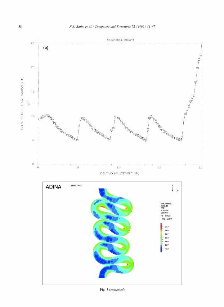
Fig. 3 (continued)
K.J. Bathe et al. / Computers and Structures 72 (1999) 31±4738

graph. In this case, the wrinkles do not get into con-tact, except in the corner of the box model, and hencethe force is almost constant after the initial maximum
value.In each case, for the cylinder and the box, large
strains are measured in the response solution, see Fig.3(c). The contact conditions were modeled by specify-ing contact surfaces at the outer and inner surfaces of
the structures and specifying that self-contact isallowed.
The two structures were also next analysed for theircrash behaviors by imposing the end displacements (d )to take place within 1 and 5 ms, respectively. Thesame ®nite element models were used and implicit timeintegration (the trapezoidal rule) was employed for the
transient solutions. Figs. 5 and 6 show the calculatedresults. It is seen that in these dynamic analyses, the
wrinkling takes place di�erently due to the signi®cantinertia forces, and of course, the calculated time vari-ations of end-forces are di�erent when compared with
the results given in Figs. 3 and 4. However, it isinteresting to note that the maximum forces reachedare almost the same in the static and dynamicanalyses.
Considering all the analyses reported upon above, itwas noted that while the overall response calculated inan analysis was not very sensitive to the mesh
employed, the actual response path (for example, themanner in which the wrinkles developed) was some-what sensitive to the ®nite element discretization used.
4.2. Crush analysis of small motor car model
The motor car ®nite element model shown in Fig. 7
Fig. 4. Crush response of box. (a) Original mesh and deformations. (b) Crushing force-time relationship.
K.J. Bathe et al. / Computers and Structures 72 (1999) 31±47 39

was analysed for its crush response. In the analysis, a
heavy steel plate, assumed to be rigid, is applied to the
front left corner of the car frame. The speed of crush-
ing is 10 mm/s (which is about 0.022 mph). These con-
ditions clearly correspond to a static analysis.
The ADINA ®nite element model was created from
a Nastran input deck from which 4-node MITC4 shell
elements were created to model the car structure and
the windshield. Spring elements are employed to model
connections between the doors and the windshield and
frame, respectively.
Fig. 7 shows the calculated crushing load using
ADINA as a function of the plate displacement. The
same model was analysed as well using the LS-DYNA
code (an explicit ®nite element program) and the calcu-
lated response is also shown in the ®gure. Considering
the LS-DYNA solution results, as expected, the calcu-
lated crushing load depends on the speed of load appli-
cation. Clearly, for a speed of 10 mph the crushing
load is much too high. This would be indicated by the
kinetic energy being too large in comparison to the
strain energy of the ®nite element system. For a speed
of 0.05 mph, which is deemed to be su�ciently close to
the actual physical speed, however, the calculated re-
sponse appears to be numerically unstable. Reasonable
results are obtained using a speed of 0.5 mph, which is
about 23 times larger than the actual physical speed of
load application. Hence, with su�cient experience in
the use of the program capabilities of an explicit code,
acceptable results can probably be obtained. However,
to reach these results some numerical experimentation
may be necessary, which can be costly. Also, for the
dynamic e�ects to be negligible, still many time steps
need to be used (of the order of 100,000 instead of the
order of one million for the actual physical speed of
load application).
Fig. 4 (continued)
K.J. Bathe et al. / Computers and Structures 72 (1999) 31±4740

Fig. 5. Crash response of cylinder. (a) Deformations. (b) Crashing force-displacement relationship. (c) E�ective plastic strain in
crashed position at d=1.9 in.
K.J. Bathe et al. / Computers and Structures 72 (1999) 31±47 41

Fig. 5 (continued)
K.J. Bathe et al. / Computers and Structures 72 (1999) 31±4742

For the ADINA solution 160 load steps were usedand the complete analysis took about 8 h on a SiliconGraphics O2000 machine.Unfortunately, for this analysis no physical test data
are available for comparison.
4.3. Crush analysis of Ford Taurus model
The Ford Taurus shell model shown in Fig. 8 wasalso analysed for its crush response. The same physical
conditions as in the above car crush analysis wereimposed.The model consists of 98,494 MITC4 shell elements,
and is governed by 580,183 ®nite element equations.The ADINA solution shown in Fig. 8 was obtainedusing a total of 120 static incremental steps with a
total run-time of about 48 h on a Hewlett Packard V-Class machine.As is seen, the calculated response is quite close to
the laboratory test data. It should be noted that only
one model was created, without any tuning, and thatmodel was run to obtain the results reported in Fig. 8.
5. Concluding remarks
The objective was to present some advances for thecrush analysis of structures. Crushing a structure is alow-speed, practically static event. However, because
of the solution di�culties with static analysis pro-grams, so far, largely transient analysis proceduresbased on explicit time integration have been used for
Fig. 6. Crash response of box. (a) Deformations. (b) Crashing force-time relationship.
K.J. Bathe et al. / Computers and Structures 72 (1999) 31±47 43

crush simulations. These analyses are computationally
very expensive, unless severe arti®cial modeling
assumptions regarding the speed of crushing, mass
density of the materials, or other analysis ingredients
are made. In addition, the transient analysis pro-
cedures may become numerically unstable at the cor-
rect physical conditions. Hence, arti®cial conditions
are frequently used with numerical experimentation to
`assure' a proper response prediction.
It is shown in this paper that, at the current state-of-
the-art, solution capabilities are available with which
the correct physical conditions can be modeled and the
static or low-speed dynamic solutions can be obtained
in an e�ective manner. Indeed, the solution times used
in the static analyses appear to be less than in the
explicit dynamic response calculations. Hence, there is
good reason to perform crush analyses in the manner
demonstrated in this paper. Of course, continued
e�orts will be made to strive for further improvements
in the static and implicit dynamic analysis capabilities,
such as provided by increasing the e�ciency of the
contact algorithm, using possibly higher-order MITC
shell elements, and through more e�ective parallel pro-
cessing. These improvements with the continuous
advances in computer hardware will render the sol-
ution of crush problems in the way demonstrated in
the paper even more attractive.
Fig. 6 (continued)
K.J. Bathe et al. / Computers and Structures 72 (1999) 31±4744
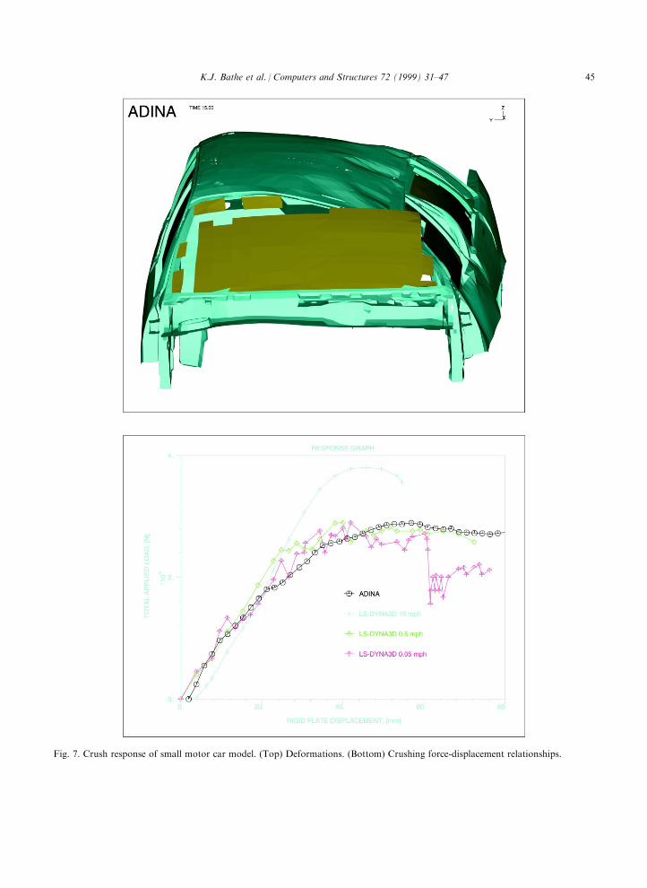
Fig. 7. Crush response of small motor car model. (Top) Deformations. (Bottom) Crushing force-displacement relationships.
K.J. Bathe et al. / Computers and Structures 72 (1999) 31±47 45

Fig. 8. Crush response of Ford Taurus car model. (Top) Mesh used (also rigid steel plate is shown). (Bottom) Deformations.
(Overleaf ) Crushing force-displacement relationship: calculated values and test data.
K.J. Bathe et al. / Computers and Structures 72 (1999) 31±4746

References
[1] Bathe KJ. Finite element procedures. Prentice Hall, 1996.
[2] Bathe KJ, Guillermin O, Walczak J, Chen H. Advances
in nonlinear ®nite element analysis of automobiles.
Computers & Structures 1997;64(5/6):881±91.
[3] Bathe KJ, Dvorkin EN. A formulation of general shell
elementsÐthe use of mixed interpolation of tensorial
components. Int J Numerical Methods in Engineering
1986;22:697±722.
[4] Chapelle D, Bathe KJ. Fundamental considerations for
the ®nite element analysis of shell structures. Computers
& Structures 1998;66(1):19±36.
[5] Bathe KJ, Iosilevich A, Chapelle D. An evaluation of the
MITC shell elements, Computers & Structures, sub-
mitted.
[6] Bathe KJ, Iosilevich A, Chapelle D. An inf-sup test for
shell ®nite elements, Computers & Structures, submitted.
[7] Chapelle D, Bathe KJ. The mathematical shell model
underlying general shell elements, Int J for Numerical
Methods in Engineering, submitted.
[8] Bathe KJ, Chaudhary AB, Dvorkin EN, Kojic M. On
the solution of nonlinear ®nite element equations. In:
Damjanic F, et al., editors. Proceedings, International
Conference on Computer-Aided Analysis and Design of
Concrete Structures I. Swansea, UK: Pineridge Press,
1984. p. 289±99.
[9] Kojic M, Bathe KJ. The `E�ective-Stress-Function' al-
gorithm for thermo-elasto-plasticity and creep.
International J for Numerical Methods in Engineering
1987;24:1509±32.
[10] Eterovic AL, Bathe KJ. A hyperelastic-based large strain
elasto-plastic constitutive formulation with combined iso-
tropic-kinematic hardening using the logarithmic stress
and strain measures. International J for Numerical
Methods in Engineering 1990;30:1099±114.
[11] Gabriel G, Bathe KJ. Some computational issues in large
strain elasto-plastic analysis. Computers & Structures
1995;56(2/3):249±67.
[12] Eterovic AL, Bathe KJ. On the treatment of inequality
constraints arising from contact conditions in ®nite el-
ement analysis. Computers & Structures 1991;40:203±9.
[13] Bathe KJ, Bouzinov PA. On the constraint function
method for contact problems. Computers & Structures
1997;64(5/6):1069±85.
[14] Graph theory and sparse matrix computation. In:
George A, Gilbert JR, Liu JWH, editors. Institute for
mathematics and its applications Vol. 56. Springer-
Verlag, 1993.
Fig. 8 (continued)
K.J. Bathe et al. / Computers and Structures 72 (1999) 31±47 47