advanced water treatment plant - un escap 2_09.00sd_case study...than 1% of the water supply on...
TRANSCRIPT

Advanced Water Treatment Plant
The case study of Ozonation and Granular Activated Carbon(GAC)
Mr.Sikvas Deesawasmongkol(Mickey)December, 2014.

o Mr.Sikvas Deesawasmongkol(Mickey)o Engineer. Engineering construction department.o B.Eng in Environmental Engineering (Chulalongkorn
University, Bangkok. Thailand)o M.Sc. in Water Resources and Environmental
Management (Faculty of Geo-Information Science and Earth Observation (ITC).University of Twente.The Netherlands.)
o MBA(Finance, Marketing, International business management)(Thammasat University, Bangkok. Thailand)
Hello! Sawasdee (krub)! Min-Ga-La-Ba!
Speaker

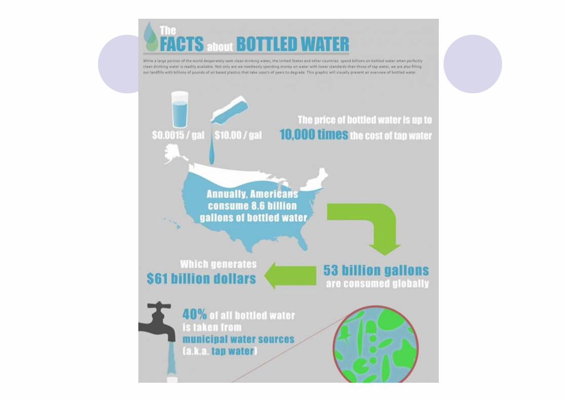
Some interesting facts about WATER!
How much water is there on earth?
Most of the earth consists of water, there is much more water than there is land.
About 70% of the earth's surface is covered in water. But water also exists in the air as vapour and in aquifers in the soil, as groundwater.
How much of the water can be found in oceans?
As oceans are very wide and there are multiple to be found on earth, oceans store most of the earth's water. This is apparently 97% of the total amount of water on earth, 2% of which is frozen.
How much freshwater is available?
Of all the water on earth, which is 97.14% of the total amount of surface water, only 2.59% is freshwater. Of this 2.59% another percentage is trapped in ice caps and glaciers, which is about 2%. The rest of the freshwater is either groundwater (0.592%), or readily accessible water in lakes, streams, rivers, etc. (0.014%)
How much water is suitable for drinking water?
From the quantities that came up in the questions listed above, one can conclude that less than 1% of the water supply on earth can be used as drinking water.

http://ga.water.usgs.gov/edu/earthwherewater.html


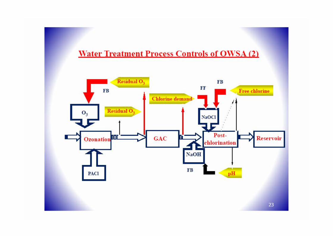
Water Supply System

Agenda
What is “our” Advanced water treatment plant means?OzonationGranular Activated Carbon(GAC)Some useful information of Japan and Korea Advanced Water Treatment plant

What is the conventional method to treat water? (1/2)
Many water treatment plants use a combination of coagulation, sedimentation, filtration and disinfection to provide clean, safe drinking water to the public. Worldwide, a combination of coagulation, sedimentation and filtration is the most widely applied water treatment technology, and has been used since the early 20th century.

What is the conventional method to treat water? (2/2)

Why? Advanced Water Treatment Plant (Advanced WTP)
Urbanization, Industrialization, Landuse, Climate, etc :
All change…change…change…Therefore;
Water pollution in rivers Water quality of raw water taken deteriorated Population affected by offensive taste and odor increasedChanges in “water preferences” over the last few decades
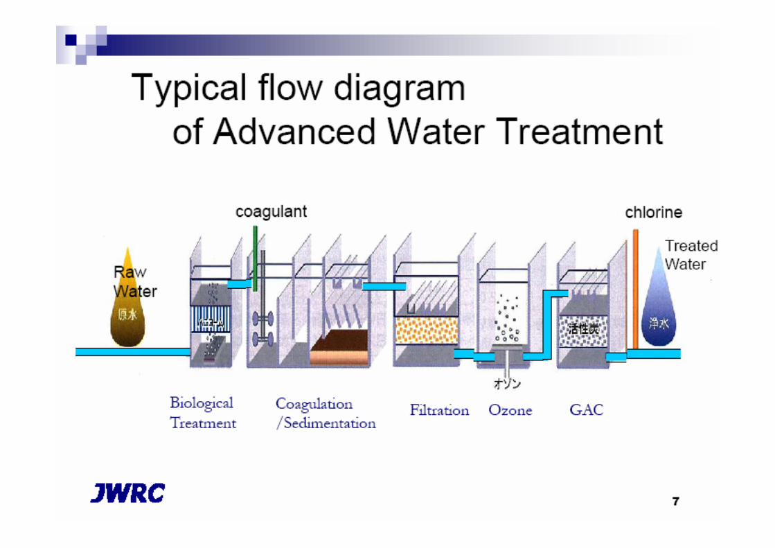
Advanced Water treatment plant…

Ozonation system
Facts: The ozonation process recently gained popularity as a treatment alternative in the united States after the regulatory agencies placed restrictions on the disinfection by-products, especially the acceptable levels of trihalomethaneOzonation system is an established and proven disinfection alternative, as well as a preoxidantfor the control of THM precursors
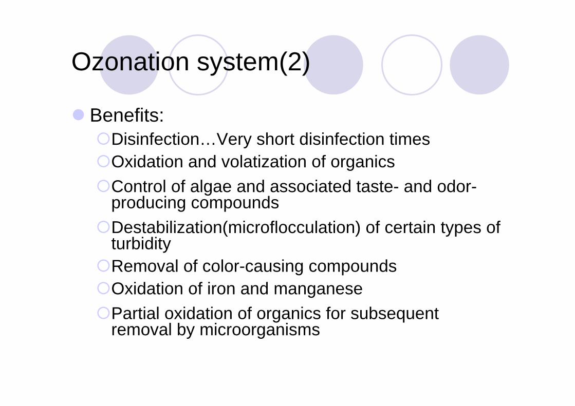
Ozonation system(2)
Benefits:Disinfection…Very short disinfection timesOxidation and volatization of organicsControl of algae and associated taste- and odor-producing compoundsDestabilization(microflocculation) of certain types of turbidityRemoval of color-causing compoundsOxidation of iron and manganesePartial oxidation of organics for subsequent removal by microorganisms
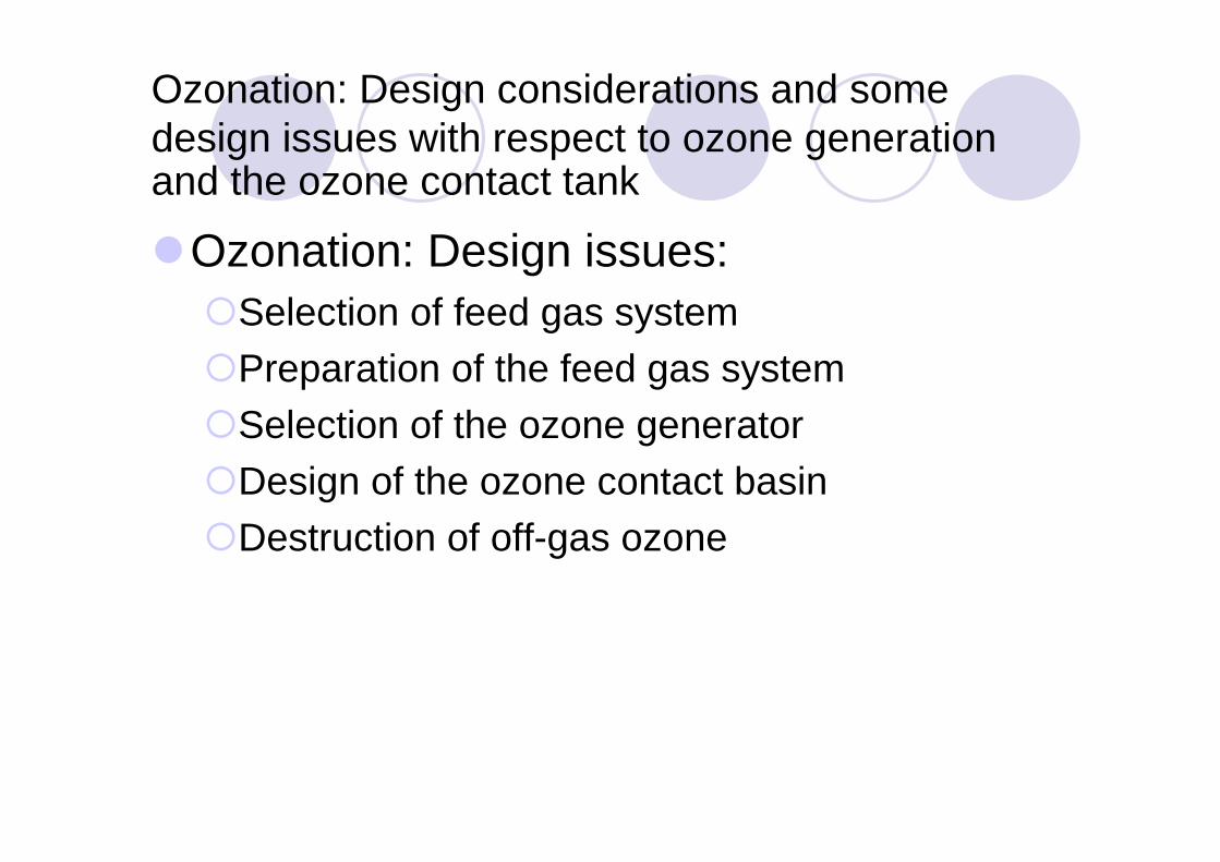
Ozonation: Design considerations and some design issues with respect to ozone generation and the ozone contact tank
Ozonation: Design issues:Selection of feed gas systemPreparation of the feed gas systemSelection of the ozone generatorDesign of the ozone contact basinDestruction of off-gas ozone

Ozone water treatment systems
have four basic components:
a gas feed systeman Ozone generatoran Ozone contactor/ Ozone contact tankan off-gas destruction system

Simplified Ozone System Schematic

A gas feed system
Table 3-2 presents a comparison of the advantages and disadvantages of each gas feed system.

Ozone Generators
The voltage required to produce ozone by corona discharge is proportional to the pressure of the source gas in the generator and the width of the discharge gap.
Theoretically, the highest yield (ozone produced per unit area of dielectric) would result from a high voltage, a high frequency, a large dielectric constant, and a thin dielectric.
However, there are practical limitations to these parameters. As the voltage increases, the electrodes and dielectric materials are more subject to failure. Operating at higher frequencies produces higherconcentrations of ozone and more heat requiring increased cooling to prevent ozone decomposition. Thin dielectrics are more susceptible to puncturing during maintenance.
The design of any commercial generator requires a balance of ozone yield with operational reliability and reduced maintenance.

Ozone Generators
Should know…In the overall production of ozone, the electrical power is a critical element because the greater the power consumption the greater the heat generation.Gas flow also affects the generation of heat; a gas flow that istoo low will cause the generator to heat up, whereas as excessively high gas flow rate will decrease ozone production.

Ozone Generators
After the type of ozone generation unit is selected, the design engineer must establish the following key design issues:
Size of the ozone generatorNumber of generatorsCost of energyAvailability and cost of oxygenType of feed gas treatment systemReliability of each componentOperation and maintenance costsOzone Contactor designDestruction of the off-gasUse of catalyst such as UV and hydrogen peroxide

An ozone contactor/ Ozone contact tank
Once ozone gas is transferred into water, the dissolved ozone reacts with the organic and inorganic constituents, including any pathogens.
Ozone not transferred into the process water during contacting is released from the contactor as off-gas.
Transfer efficiencies of greater than 80 percent typically are required for efficient ozone disinfection (DeMers and Renner, 1992).
The effective mixing of ozone and process water is critical in maximizing the performance of the ozonation system.

An ozone contactor/ Ozone contact tank
Common ozone dissolution methods include:
Bubble diffuser contactors/ Diffused bubblesConcurrentCountercurrent
InjectorsPositive pressure injection (U-tube)Negative pressure injection (Venturi tube)
Turbine mixers/ Turbine mixer tankPacked tower
The countercurrent bubble contactor is considered to be the mostefficient and cost effective of the alternatives and has been employed in the design of most ozonation systemDue to the rapid reaction kinetics of ozone, a contact time of only 3 –10 min is considered to be a practical detention time for the contactor

An ozone contactor/ Ozone contact tank
The tanks must be completely enclosedThey are composed of concrete and are primarily located outsideEach tank has two cells and is capable of handling 50% of the maximum daily flow of the plantEach cell should have a drain to allow periodic dewatering and cleaningStainless steel hatches should be provided to facilitate inspection and maintenanceA slight negative pressure(2 in. of water) should be maintained in the tank to ensure that there is no leakage of ozone above the water surfaceAll pipe(SS304 or SS316) connections should be welded or flanged inside the tank and a check valve should be installed in the gas feed line prior to the contactor to prevent the backflow of water into the gas lineThe water depth of the tank should be 18-20 ft (5.5 – 6 m.) to provide a minimum ozone transfer efficiency of 95%.

Bubble Diffuser Contactors
The bubble diffuser contactor is commonly used for ozone contacting in the United States and throughout the world (Langlais et al., 1991).
This method offers the advantages of no additional energy requirements, high ozone transfer rates, process flexibility,
operational simplicity, and no moving parts.
Figure 3-7 illustrates a typical three stage ozone bubble diffuser contactor. This illustration shows a countercurrent flow configuration (ozone and water flowing in opposite directions), an alternating cocurrent/countercurrent arrangement, and a cocurrent flow configuration(ozone and water flowing in the same direction).
Also, the number of stages can vary from two to six for ozone disinfection, with the majority of plants using two or three chambers for contacting and reaction (Langlais et al., 1991).

Bubble Diffuser Contactors

Schematic of a three-stage, bubble diffuser ozone contact basin.(Adaptedfrom EPA Design Manual, EPA/625/1-86/02, Oct. 1986)

Bubble Diffuser Contactors

Injector Dissolution
The injector contacting method is commonly used in Europe,
Canada, and the United States (Langlais et al., 1991).
Ozone is injected into a water stream under negative pressure,
which is generated in a venturi section, pulling the ozone into the water stream.
In many cases, a sidestream of the total flow is pumped to a higher pressure to increase the available vacuum for ozone injection. After the ozone is injected into this sidestream, the sidestream containing all the added ozone is combined with the remainder of the plant flow under high turbulence to enhance dispersion of ozone into the water.

Injector Dissolution

Injector Dissolution
Table 3-5 summarizes the advantages and disadvantages of injection contacting (Langlais et al., 1991).

Off-Gas Destruction
The ozone contact tank typically has a 90-95% transfer of ozone to the water, the remaining 5-10% result as off-gas.The ozone content of this off-gas must be reduced to levels below the OSHA and local Air Quality Management District(AQMD) standards prior to venting into the atmosphere.According to OSHA, the maximum allowable ambient concentration of ozone is 0.0002 g/m3 (0.1 ppm by volume) for an 8 hr working day.The off-gas normally contains levels greater than 1 g/m3 (500 ppmby volume).Three basic methods of destruction have been used: thermal destruction, thermal destruction with a catalyst, and catalytic destruction.

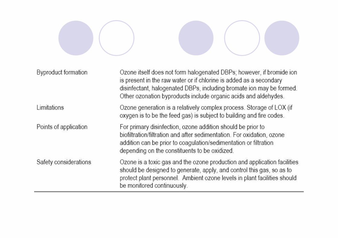
Safety
The issue of safety must be addressed because ozone is both a toxic gas and a fire hazard. Moreover, if the system uses oxygen as the feed gas, the situation becomes more dangerous.Although the ozonation system may be less hazardous than the chlorination system because it can be shut down if an ozone leakdevelops, it may also be more dangerous because the system must use high-voltage electrical power to generate the ozone.

Safety(2)
The American Industrial Hygiene Association(AIHA), OSHA, and other associations recommend the following permissable levels of ozone in the air:
Workers will not be exposed to ozone concentrations in excess of a time weighted average of 0.2 mg/m3 (0.1 ppm by volume) for eight hours or more per workday, and that no worker be exposed to a ceiling concentration of ozone in excess of 0.6 mg/m3 (0.3 ppm by volume) for more than 10 minutes
Local Air Quality Management Districts may have more stringent criteria that are part of the restrictions on smog.Other safety considerations:
Installation of self-contained breathing apparatuses in the event of a severe ozone leak,Installation of eyewashs and emergency showerComprehensive safety and operation and maintenance manuals
Ideally, the ozone generation building and ozone contact tanks are isolated from the operations building for obvious safety reasons

Design Criteria
The design criteria for the Ozonationsystem are numerous. They range from the ozone generator, to the contact tank, to the destruction unit. The requirements for these and many more issues are...

Design CriteriaOzone dosage 1.5 - 3 mg/L(normal) depending on the purpose
Number of ozone generators Minimum of two, and preferably three; one always acts as a standby
Ozone generator
Minimum production 10-20% of rated capacity
Maximum production 75% of rated capacity
Cooling water temperature Less than 75F(24C) at the inlet
Vessel construction Pressure vessel (15 psig) constructed with 304 LSS or 315 LSS with Hypalon or Teflon gaskets
Type of generator Low frequency with variable voltage, medium frequency with frequency control, or another type, depending on the selection
Compressor
Pressure 10-40 psig if heat reactive desiccant; 80-100 psig if pressure swing type desiccant
Number Minimum of two; one acts as standby
Type Liquid ring(<1000 lb/day ozone production),
Centrifugal(>1000 lb/day ozone production),
Piston type, oil-free, or oil lubricated with oil removal filters(<100 lb/day-small plant)

Design Criteria
Filters
Before compressor Regular filter with silencer
Before dryer 3-5 um
Before generator 0.3 um
Pressure drop 0.5 psi when clean, 2 psi for coalescing filter
Moisture removal
Refrigerant dryer 41F(5C) dewpoint (80% removal from air)
Desiccant dryer -76F(-60C) dewpoint (99.98% removal from air)

Design Criteria
Ozone contact tanks
Number of tanks Minimum of two
Transfer efficiency Minimum of 95% if possible; may range from 90 to 95%
Detention time 5-15 min(usually less than 8 min)
Stage of contact Normally two to three stages
Water depth 18-20 ft
Submergence of diffuser 16-18 ft
Freeboard 4-6 ft to allow the deposition of foam

Design CriteriaOzone diffuser
Material 304 LSS, glass, ceramic, or Teflon
Bubble size 2-5 mm
Gas flow 0.5 - 4 cfm depending on the diffuser:
(each difuser) Rod diffuser (2.5 in. x 24 in. L): 4 cfm maximum
Disk difuser (7 in. diameter): 1.25 cfm maximum
Disk difuser (9 in. diameter): 1.8 cfm maximum
Headloss Maximum of 0.5 psi
Permeability 8-20 cfm/ft2
Porosity 35-45%
Residualozone(ozonated water) UV ozone monitor (continuous monitoring)
monitoring Type such as PCI Model HC or potassium iodide monitoring

Design Criteria
Ozone destruction unit
Type Heat catalyst unit (most popular)
Temperature 80 - 100 F (27 - 38 C)
Catalyst Metal (platinum) or metal oxides: these catalysts are proprietary items
Primary Uses and Points of Application of Ozone
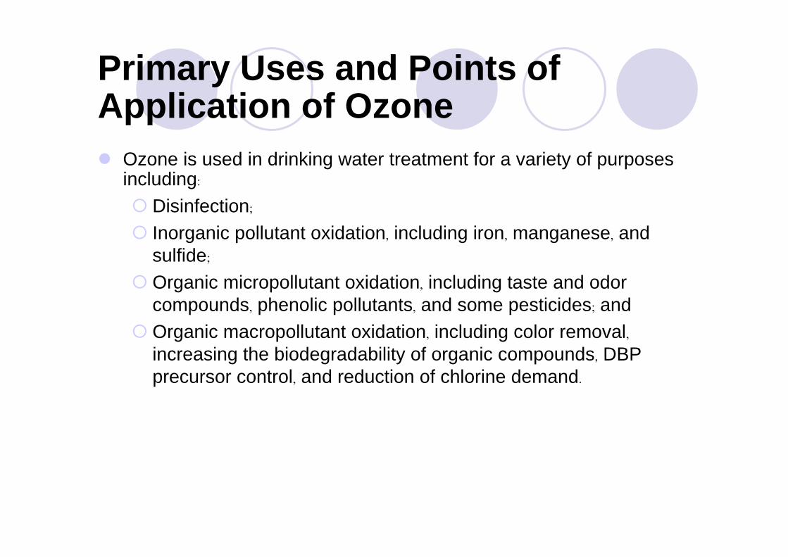
Ozone is used in drinking water treatment for a variety of purposes including:
Disinfection;
Inorganic pollutant oxidation, including iron, manganese, and sulfide;
Organic micropollutant oxidation, including taste and odor compounds, phenolic pollutants, and some pesticides; andOrganic macropollutant oxidation, including color removal,increasing the biodegradability of organic compounds, DBP precursor control, and reduction of chlorine demand.

Disinfection
Ozone is a powerful oxidant able to achieve disinfection with less contact time and concentration than all weaker disinfectants, such as chlorine, chlorine dioxide, and monochloramine (Demers and Renner, 1992).
However, ozone can only be used as a primary disinfectant since it cannot maintain a residual in the distribution system.
Thus, ozone disinfection should be coupled with a secondary disinfectant, such as chlorine, chloramine, or chlorine dioxide for a complete disinfection system.

Iron and Manganese Oxidation
Ozone will oxidize iron and manganese, converting ferrous (2+) iron into the ferric (3+) state and 2+ manganese to the 4+ state. The oxidized forms will precipitate as ferric hydroxide and manganese hydroxide (AWWA, 1990). The precise chemical composition of the precipitate will depend on the nature of the water, temperature, and pH.
The ozone dose required for oxidation is 0.43 mg/mg iron and 0.88
mg/mg manganese (Langlais et al., 1991). Iron oxidizes at a pH of 6-9
but manganese is more effective at a pH of around 8. Also, over-
ozonation has no effect on iron, but will resolubilize manganese,
which then should be reduced to manganese dioxide downstream.

Oxidation of Taste and Odor Compounds
Ozone is used to oxidize/destroy taste and odor-causing compounds because many of these compounds are very resistant to oxidation.
Suffet et al. (1986) confirmed that ozone is an effective oxidant for use in taste and odor treatment. They found ozone doses of 2.5 to 2.7 mg/L and 10 minutes of contact time (ozone residual of 0.2 mg/L) significantly reduced taste and odors in the specific waters they tested.
Most early U.S. water plants (i.e., 1940-1986) installed ozonation specifically for taste and odor removal.

Points of Application
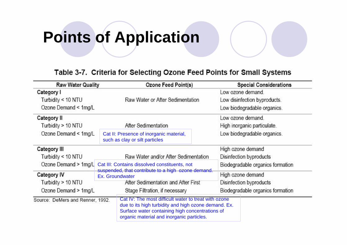
The typical locations for feeding ozone in a water treatment plant are at the head of the treatment plant (raw water) pre-ozonation and after sedimentation.
Raw water quality and turbidity and ozone demand (the amount of ozone required for all oxidation requirements of the water) can be used to assess how to use ozone in the treatment process.
Table 3-7 lists the criteria for selecting ozone feed points based on these two parameters.
By moving the ozonation process further downstream after sedimentation, the ozone demand and production of byproducts are reduced. The advantage of placing ozone ahead of filtration is that biodegradable organics produced during ozonation can be removed by subsequent biological activity in the filters.
Points of Application
Cat II: Presence of inorganic material, such as clay or silt particles
Cat III: Contains dissolved constituents, not suspended, that contribute to a high ozone demand. Ex. Groundwater
Cat IV: The most difficult water to treat with ozone due to its high turbidity and high ozone demand. Ex. Surface water containing high concentrations of organic material and inorganic particles.

Ozonation Disinfection Byproducts
Ozone does not form halogenated DBPs (TTHMs and HAA5s) when participating in oxidation/reduction reactions with NOM but it does form a variety of organic and inorganic byproducts.
Table 3-9 and Figure 3-11 show the principal known byproducts associated with ozonation.
However, if bromide ion is present in the raw water halogenated DBPs may be formed. These brominated DBPs appear to pose a greater health risk than non-brominated DBPs.

Ozonation Disinfection Byproducts
Although ozone is an effective oxidant and disinfectant, it should not be relied upon as a secondary disinfectant to maintain a residual in the distribution system.
Monochloramine is attractive for this purpose because it produces little to no halogenated DBPs.
Chlorine is a candidate for secondary disinfectant but the ozonated water may actually produce either more or less DBPs following the addition of free chlorine depending on the nature of the organicmaterial following ozonation unless biologically active filtration precedes the addition of chlorine.
The principal benefit of using ozone for controlling DBP formation is that it allows free chlorine to be applied later in the treatment process after precursors have been removed and at lower doses,
thereby reducing DBPFP.

Ozonation Disinfection Byproducts

Ozonation Disinfection Byproducts
Ozonation of a source water containing bromide ion can produce brominated byproducts, the brominated analogues of the chlorinated DBPs.Song et al. (1997) found that bromate ion formation is an important consideration for waters containing more than 0.10 mg/L bromide ion. These brominated byproducts include bromate ion, bromoform, the brominated acetic acids and acetonitriles, bromopicrin, and cyanogen bromide (if ammonia is present). An ozone dose of 2 mg/L produced 53 mg/L of bromoform and 17 mg/L of dibromoacetic acid in a water containing 2 mg/L of bromide ion (McGuire et al., 1990). Ozonation of the same water spiked with 2mg/L bromide ion showed cyanogen bromide formation of 10 mg/L (McGuire et al., 1990). Furthermore, ozone may react with the hypobromite ion to form bromate ion (Amy and Siddiqui, 1991; Krasner et al., 1993), a probable human carcinogen (Regli et al., 1992). Bromate ion concentrations in ozonated water up to 60 mg/L have been reported (Amy and Siddiqui, 1991; Krasner et al., 1993).
Note that the amount of bromide ion incorporated into the measured DBPs accounts for only one-third of the total raw water bromide ion concentration.
This indicates that other brominated DBPs exist that are not yet identified (Krasner et al., 1989; MWDSC and JMM, 1992). Figure 3-12 shows the major pathways for bromate ion formation.

Operational Considerations: Process Considerations
Because ozone is such a strong oxidant, it will react with many organic and inorganic compounds present in the water.
Ozone is used to remove tastes and odors by breaking down organic compounds, and to aid in the removal of iron and manganese by oxidizing these compounds to less soluble forms.
These demands should be satisfied before any ozone is available to satisfy primary disinfection requirements. The presence and concentration of these compounds can dictate the location of ozone addition, depending on the process goals.

Operational Considerations: Space Requirements
Storage of LOX is subject to regulations in building and fire codes.
These regulations will impact the space requirements and may dictate the construction materials of adjacent structures if the certain setback requirements cannot be met.
In general, the footprint for ozone generated from air is smaller than that required for chloramination and chloride dioxide applications.
However, the footprint area for ozone generated from pure oxygen is comparable to that of chlorine dioxide because of the additional area needed for storage.

Operational Considerations: Material Selection
Ozone-resistant materials should be used from the ozone generators through the off-gas destruct unit.
If oxygen is used for the feed gas, oxygen resistant materials should be used up to the generators.
Pure oxygen piping should be specially cleaned after installation for oxygen service, which increases construction cost.
Materials for air preparation systems can be those normally used for compressed air systems.
Langlais et al. (1991) recommended that piping beyond the desiccant dryers be ozoneresistant, as some backflow and ozone diffusion can occur.
If a receiver is provided following the desiccant dryer, the piping should be ozone-resistant, downstream of the pressure regulator.Ozoneresistant (oxygen resistant as well if high purity oxygen is the feed gas) check valves should be placed in the piping ahead of the generator.
Operational Considerations: Material Selection(2)
Ozone-resistant materials include the austenitic (300 series) stainless steels, glass and other ceramics, Teflon and Hypalon, and concrete.The 304 series stainless steels can be used for “dry” ozone gas (also for oxygen), 316 series should be used for “wet” service. Wet service includes piping in the contactors and all off-gas piping and the off-gas destruct unit. Teflon or Hypalon should be used for gasket materials. Concrete should be manufactured from Type II or Type IV cement.Typical practice in the United States is to provide 3 inches of cover for reinforcing to prevent corrosion by either ozone gas or ozone in solution, although Fonlupt (1979) reports that 4 cm (1.13 inches) is adequate for protection. Hatches for access into contactors should be fabricated from 316 series stainless steels and provided with ozone-resistant seals.

Operational Considerations: Ozone System Maintenance
Stolarik and Christie (1997) provide a good overview of the operational and maintenance requirements during the 10 years of operating the 600 mgd Los Angeles Aqueduct Filtration and Ozone Plant.
The ozone system has been available 97.1 percent of the time over the 10 year period.
Fuse failure and generator cleaning comprised the major maintenance chores on the ozone generators during the first years.
Fuse failure was caused by a malfunction when its glass dielectric tube failed.
Vessels are cleaned every three years or when exit gas temperatures rise due to Fe3O4 deposits on the ground electrode/heat exchanger surfaces.
Rod shaped ceramic diffusers worked well as ozone diffusers for the initial two years. These were replaced by sintered stainless steel and ultimately a modified ceramic diffuser.

Ozone Safety
Concern for safety even at the risk of being overcautious, would be to follow practices that have been successfully applied to otheroxidants over the years.
This would be to generally isolate the ozonation system from theremainder of the plant. This should not be interpreted to mean a separate building, but rather separate rooms, separate exterior entrances, separate heating and ventilation systems, noise control,etc. This method already is manifested in some of the European ozonation plants, but on a lesser scale.

Ozone Safety
Ozone generators should be housed indoors for protection from the environment and to protect personnel from leaking ozone in the case of a malfunction.
Ventilation should be provided to prevent excess temperature rise in the generator room, and to exhaust the room in the case of a leak.
Adequate space should be provided to remove the tubes from the generator shell and to service the generator power supplies. Air prep systems tend to be noisy; therefore, it is desirable to separate them from the ozone generators.
Off-gas destruct units can be located outside if the climate is not too extreme. If placed inside, an ambient ozone detector should be provided in the enclosure.
All rooms should be properly ventilated, heated, and cooled to match the equipment-operating environment.

Ozone SafetyContinuous monitoring instruments should be maintained to monitor levels of ozone in the rooms.
Self-contained breathing apparatuses should be located in hallways outside the rooms liable to ozone hazards. Ambient ozone exposure levels, which have been proposed by appropriate U.S. organizations, are summarized below.
The maximum recommended ozone levels are as follows:
Occupational Safety and Health Administration. The maximum permissible exposure to airborne concentrations of ozone not in excess of 0.1 mg/L (by volume) averaged over an eighthour work shift.
American National Standards Institute/American Society for testing Materials(ANSI/ASTM). Control occupational exposure such that the worker will not be exposed to ozone concentrations in excess of a time weighted average of 0.1 mg/L (by volume) for eight hours or more per workday, and that no worker be exposed to a ceiling concentration of ozone in excess of 0.3mg/L 9by volume) for more than ten minutes.
American Conference of Government Industrial Hygienists (ACGIH).Maximum ozone level of 0.1 mg/L (by volume) for a normal eight hour work day or 40 hour work week, and a maximum concentration of 0.3 mg/L (by volume) for exposure of up to 15 minutes.
American Industrial Hygiene Association. Maximum, concentration for eight hour exposure of 0.1 mg/L (by volume).

Ozone Safety
There is a question of whether prolonged exposure to ozone may impair a worker’s ability to smell or be aware of ozone levels at less than critical levels. Awareness of an odor of ozone should not be relied upon.
Instrumentation and equipment should be provided to measure ambient ozone levels and perform the following safety functions:
Initiate an alarm signal at an ambient ozone level of 0.1 mg/L (by volume).Alarms should include warning lights in the main control panel and at entrances to the ozonation facilities as well as audible alarms.
Initiate a second alarm signal at ambient ozone levels of 0.3 mg/L (by volume). This signal would immediately shut down ozone generation equipment and would initiate a second set of visual and audible alarms at the control panel and at the ozone generation facility entrances.
An emergency ventilation system capable of exhausting the room within a period of 2 to 3 minutesalso would be interconnected to the 0.3 mg/L ozone level alarm.

Ozone Safety
Ozone gas is a hazardous gas and should be handled accordingly.
Ambient ozone levels should be monitored and equipment shut-
down and alarmed when levels exceed 0.1 ppm.
Emergency ventilation is typically provided for enclosed areas.
Building and fire codes will provide additional guidance.
The OSHA exposure limit for an 8-hour shift is 0.1 ppm by volume.
The pungent odor of ozone will provide warning to operators of any possible ozone leak.

Summary: Advantages and Disadvantages of Ozone Use
AdvantagesOzone is more effective than chlorine, chloramines, and chlorine dioxide for inactivation of viruses,Cryptosporidium, and Giardia.
Ozone oxidizes iron, manganese, and sulfides.
Ozone can sometimes enhance the clarification process and turbidity removal.Ozone controls color, taste, and odors.
One of the most efficient chemical disinfectants, ozone requires a very short contact time.
In the absence of bromide, halogen-substitutes DBPs are not formed.
Upon decomposition, the only residual is dissolved oxygen.
Biocidal activity is not influenced by pH.

Summary: Advantages and Disadvantages of Ozone Use
DisadvantagesDBPs are formed, particularly by bromate and bromine-substituted DBPs, in the presence of bromide, aldehydes, ketones, etc.
The initial cost of ozonation equipment is high.
The generation of ozone requires high energy and should be generated on-site.
Ozone is highly corrosive and toxic.
Biologically activated filters are needed for removing assimilable organic carbon and biodegradable DBPs.
Ozone decays rapidly at high pH and warm temperatures.
Ozone provides no residual.Ozone requires higher level of maintenance and operator skill.

Granular Activated Carbon(GAC)
Facts & purposeUsed as a substitute for granular filter mediumUsed as an additional process in the conventional treatment process, for the removal of organic compounds, including disinfection by products, those producing taste and odor, pesticides, and other synthetic organic compounds.++ Has been proved to be effectively in removing these various organic compounds and even organic mercury++ Not only capable of functioning in the same manner as ordinary filters-removal of suspended matter but also removes organic compounds.

Characteristics of GAC
GAC may be manufactured from a variety of materials: wood, nut shells, coal, peat, or petroleum residues.GAC used in water treatment is usually produced from bituminous or lignite coal through slow furnace heating under anaerobic conditions. The absence of oxygen ensures that the coal does not burn but transformed into a porous carbon material.

GAC
According to the Calgon Bulletin, the physical properties of GAC are as follows:
Total surface area of GAC 890 – 900 m2/gBulk density of wetter GAC 30 lb/ft3Particle density 1.4 – 1.5 g/cm3Effective size 0.8 – 0.9 mm for Filtrasorb 100
0.55 – 0.65 mm for Filtrasorb200
Uniformity coefficient 1.9 for Filtrasorb 1001.7 for Filtrasorb 200
Iodine Number 850 – 875Abrasion number 70 – 86Moisture as packed 0.5 – 2 %

GAC : Design ConsiderationThe major design considerations of the GAC contactors are:
The designed flow rate and available headloss for this processThe nature and amount of all organic compounds in the water supplyThe MCLs of the regulated organic compoundsThe overall treatment process train and each unit processThe type of GACThe size of the GACThe filtration rate (superficial velocity)The empty bed contact time (EBCT)The type of contact unitThe location of the GAC contactor in the process trainThe regeneration frequency and the method to do it

Three important issues
Select the proper size and specific gravity of GAC so that both GAC bec and sand or anthracite layers are fluidized to the same degree during backwash; that is, both GAC and other types if media in a filter cell must be hydraulically matched during the filter washing period. Otherwise, GAC is either washed out or become dirty and clogged with suspended matter and biomass.

Three important issues
The second design issue is to provide a proper L/d ratio across the filter bed. Since the filter bed does not act as an adsorption bed but as a filtration and adsorption bed, the turbidity of the filter effluent should be less than 0.1 ntu as a goal.
Three important issues
The third issue is the size and gradation of the GAC grains. For the adsorption process, GAC of small size and with a high uniformity coefficient is preferable. The filtration process, however, requires a larger size with a small uniformity coefficient; this is essential for the longer filter run and to achieve good effluent quality

GAC
Modern filter beds, including GAC, are composed of media with an effective size of 1.2 to 1.5 mm, with a uniformity coefficient of less than 1.4, and have a bed depth of 6 to 7 ft.(1.8 to 2.1 m.) with or without a sand barrier at the bottom
GAC
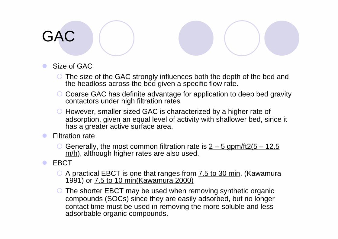
Size of GACThe size of the GAC strongly influences both the depth of the bed and the headloss across the bed given a specific flow rate.Coarse GAC has definite advantage for application to deep bed gravity contactors under high filtration ratesHowever, smaller sized GAC is characterized by a higher rate of adsorption, given an equal level of activity with shallower bed, since it has a greater active surface area.
Filtration rateGenerally, the most common filtration rate is 2 – 5 gpm/ft2(5 – 12.5 m/h), although higher rates are also used.
EBCTA practical EBCT is one that ranges from 7.5 to 30 min. (Kawamura 1991) or 7.5 to 10 min(Kawamura 2000)The shorter EBCT may be used when removing synthetic organic compounds (SOCs) since they are easily adsorbed, but no longer contact time must be used in removing the more soluble and less adsorbable organic compounds.
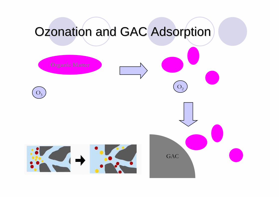
OzonationOzonation and GAC Adsorptionand GAC Adsorption
Organic Matter
O3O2
GAC

77
Criteria JAPAN KOREA MWA Propose
Ozonation
Ozone dosage (mg/l) 2.0 (max.) 2.0 2.5
Ozone : TOC 1:1 NA 1:1
Ozone contact time (min) 7.1-9.5 15.6 10
Oxygen supply Oxygen generator Oxygen gas Oxygen generator
Oxygen generator type Pressure swing
adsorption
Product from
industries
Pressure swing
adsorption
Mixing type Diffuser Side stream injection Diffuser
Of gas unit Manganese catalytic Metal catalyst Manganese catalytic
OzonationOzonation and GAC Criteriaand GAC Criteria
78
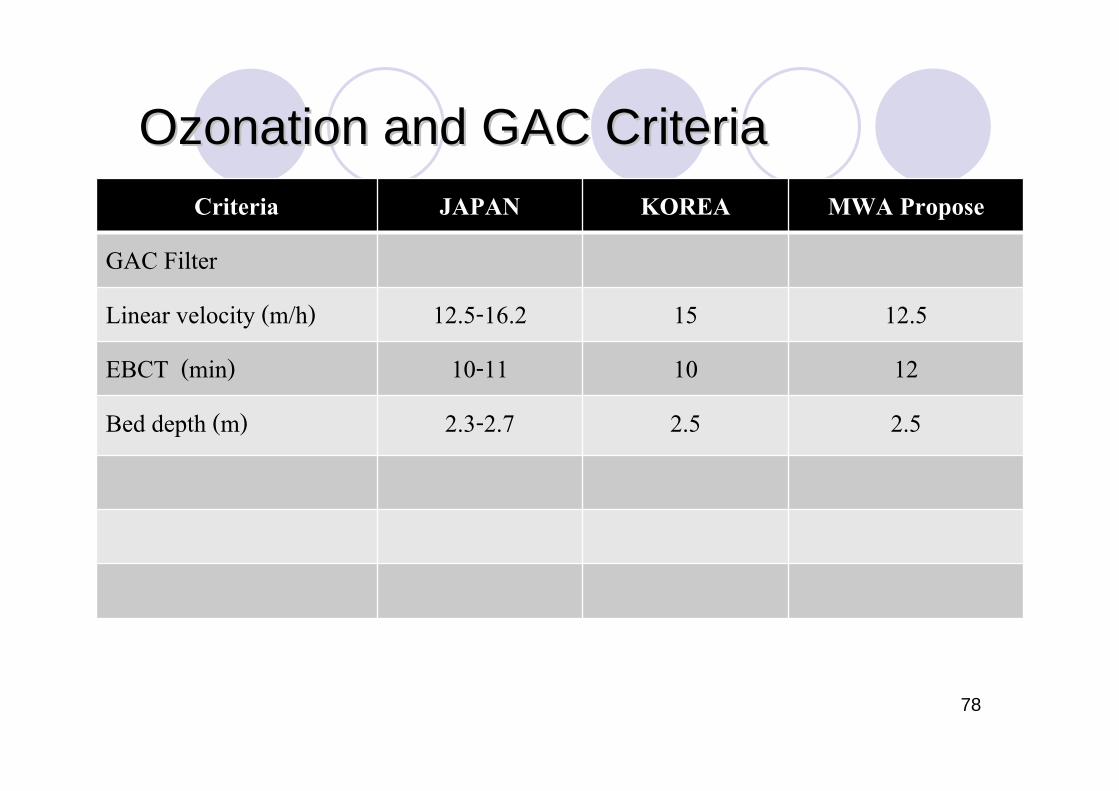
Criteria JAPAN KOREA MWA Propose
GAC Filter
Linear velocity (m/h) 12.5-16.2 15 12.5
EBCT (min) 10-11 10 12
Bed depth (m) 2.3-2.7 2.5 2.5
OzonationOzonation and GAC Criteriaand GAC Criteria

The WTP story from Japan
Osaka Murano WTP


Typical flow diagram of Advanced Water Treatment in Japan
Ozone GACFiltrationCoagulation/ Sedimentation
Biological Treatment
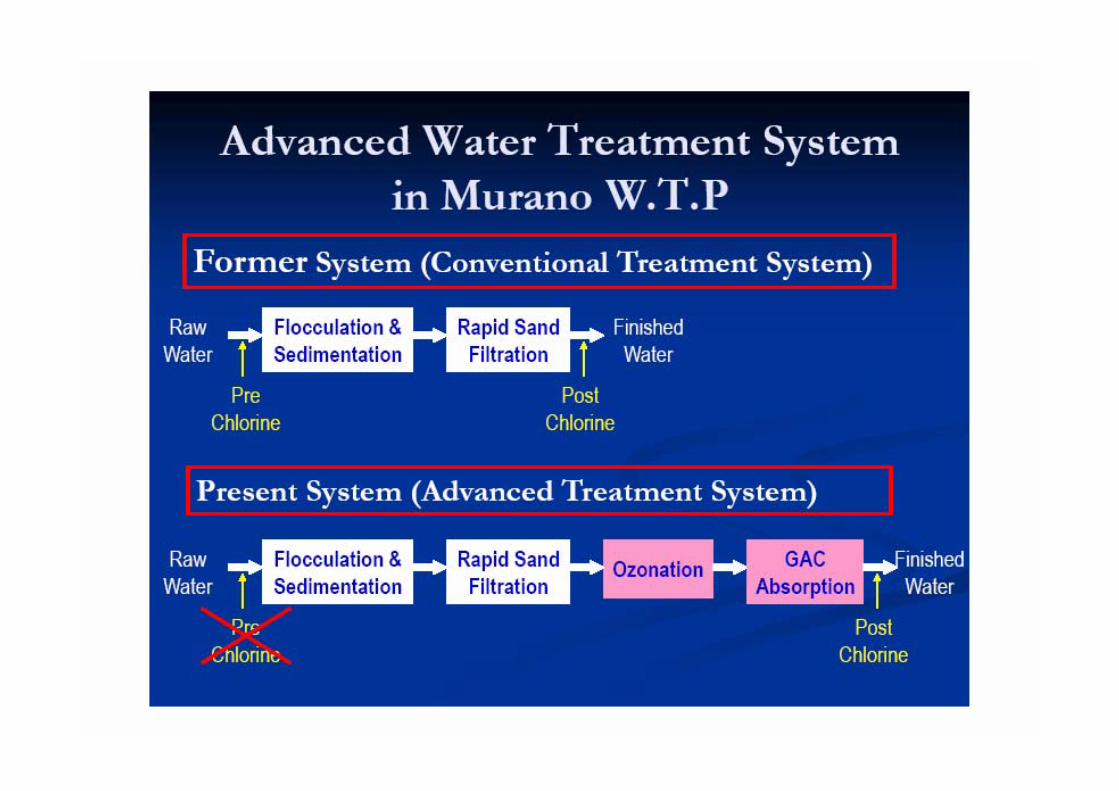


Advanced Water Advanced Water TreatmentTreatment
ถังตกตะกอน โรงงานผลิตน้ํา Murano

Advanced Water Advanced Water TreatmentTreatment

Advanced Water Advanced Water TreatmentTreatment

Advanced Water Advanced Water TreatmentTreatment
Rapid Sand FilterRapid Sand FilterMuranoMurano WTPWTP


Specification of Ozonation Facility (W+E Line)
Type of ozone generator Multiple-cylinder , corona discharge generator
Type of feed gas Air
Air treatment system Cooler and dryer
Ozone dosing ratio Maximum 2 mg/L
Ozone output 27.5 kg/h X 5 units
Ozone concentration 20 g/Nm3
Volume of ozonized air 1,375/ Nm3
Contact method Counter-current 3 stage contact
Contact time 7.5 min
Mixing system Vertical baffling
Capacity 6,900 m3/h per basin
Ozone contact basin 8 basin WxLxD = 11x12.3x6 m
Off-gas destruction Manganese dioxide catalytic decomposition
Diffuser type Ceramic cylindrical diffuser tube
Pore diameter 50-60 μm
Total number of diffuser tube 1,440
Power consumption Max 1,600 kW , Min 500 kW

Specification of GAC Treatment Facility (W+E Line)
Construction Downflow gravity natural equilibrium system
Space velocity Approx. 6.0 (1/h)
Linear velocity Approx. 16.2 (m/h)
Total basin area Approx. 113.6 m2 X 32 basins
Approx.(W) 4.0m x (L) 14.2m x 2
GAC bed depth 2.7m
Type Coal-base GAC
Granular diameter Average Approx. 1.0 mm
Hardness Over 90 (%)
Uniformity coefficient 1.5 – 1.9
Packing density Over 0.45 (g/ml)
Volume of GAC used Approx. 9,800 m3 (W+E Line)
Lower catchment unit Unit type porous plate system
Washing method Simultaneous air/water washing
Washing water Activated-carbon self-treated water
Exhaust ozone treatment Activated-carbon catalytic cracking method


Ozone Generator: Osaka Murano WTP

Ozone Generator: Osaka Murano WTP

ถัง Ozone Contact Basin

ถัง Ozone Contact Basin
Diffuser

ระบบกําจัด Ozone ส่วนที่เหลือจากถัง Ozone Contact Basin
ไม่ให้เกิน 0.06 ppm ก่อนปล่อยออกสู่บรรยากาศ


Granular Activated Carbon

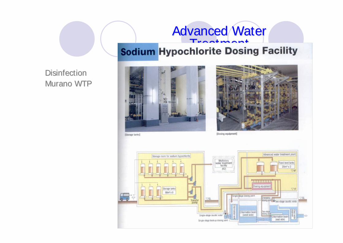
Advanced Water Advanced Water TreatmentTreatment
DisinfectionDisinfectionMuranoMurano WTPWTP

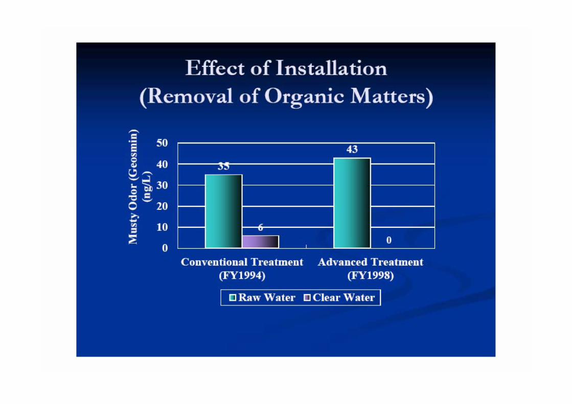
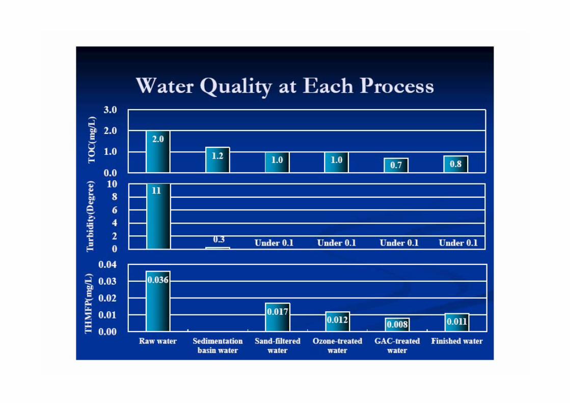


Effect on Water Quality of Advanced Water Treatment (Murano Plant, Osaka)
http://www.jwrc-net.or.jp/aswin/projects-activities/rd_files/jp-sg_symposium/2012_07_01.pdf

Advanced water treatment plant

After Advanced WTP is introduced…In Summary

The WTP story from Korea
K-water WTP
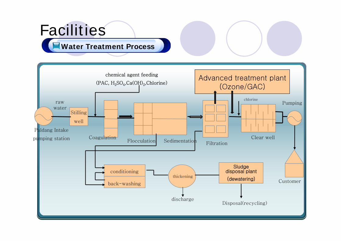
FacilitiesWater Treatment Process
Stilling
well
chemical agent feeding
(PAC, H2SO4,Ca(OH)2,Chlorine)
Disinfection
Paldang Intake
pumping station CoagulationFlocculation Sedimentation Filtration
Sludge disposal plant
(dewatering) Customerthickening
discharge
rawwater
conditioning
back-washing
Disposal(recycling)
Pumping
Advanced treatment plant(Ozone/GAC)
Clear well
chlorine
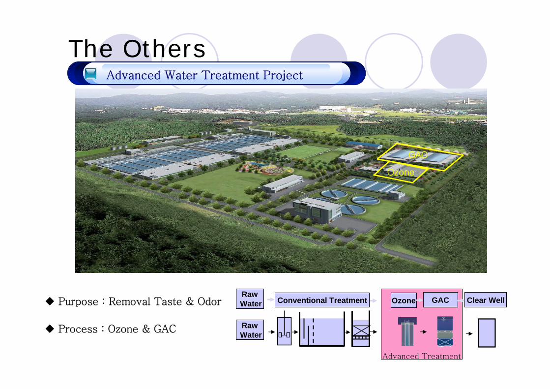
The OthersAdvanced Water Treatment Project
Purpose : Removal Taste & Odor
Process : Ozone & GAC
Ozone
GAC
Advanced Treatment
RawWater Conventional Treatment Ozone GAC Clear Well
RawWater

Ozone generator

Ozone generator

Side-stream Ozone Injection
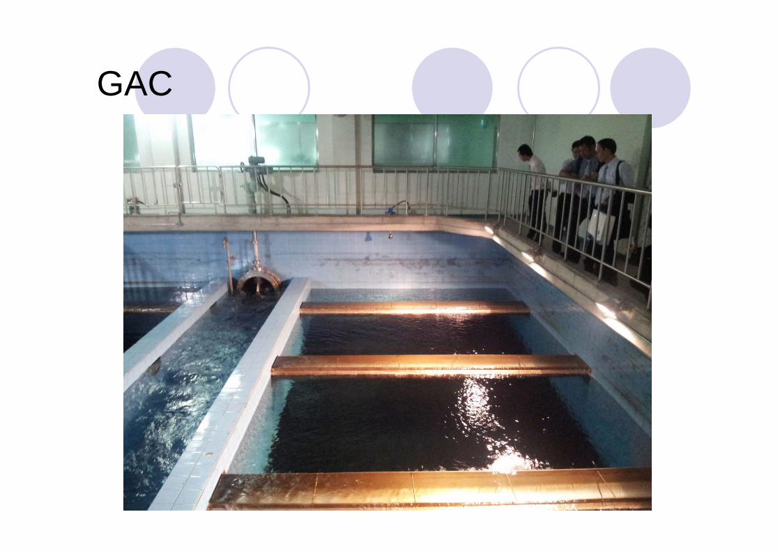
GAC
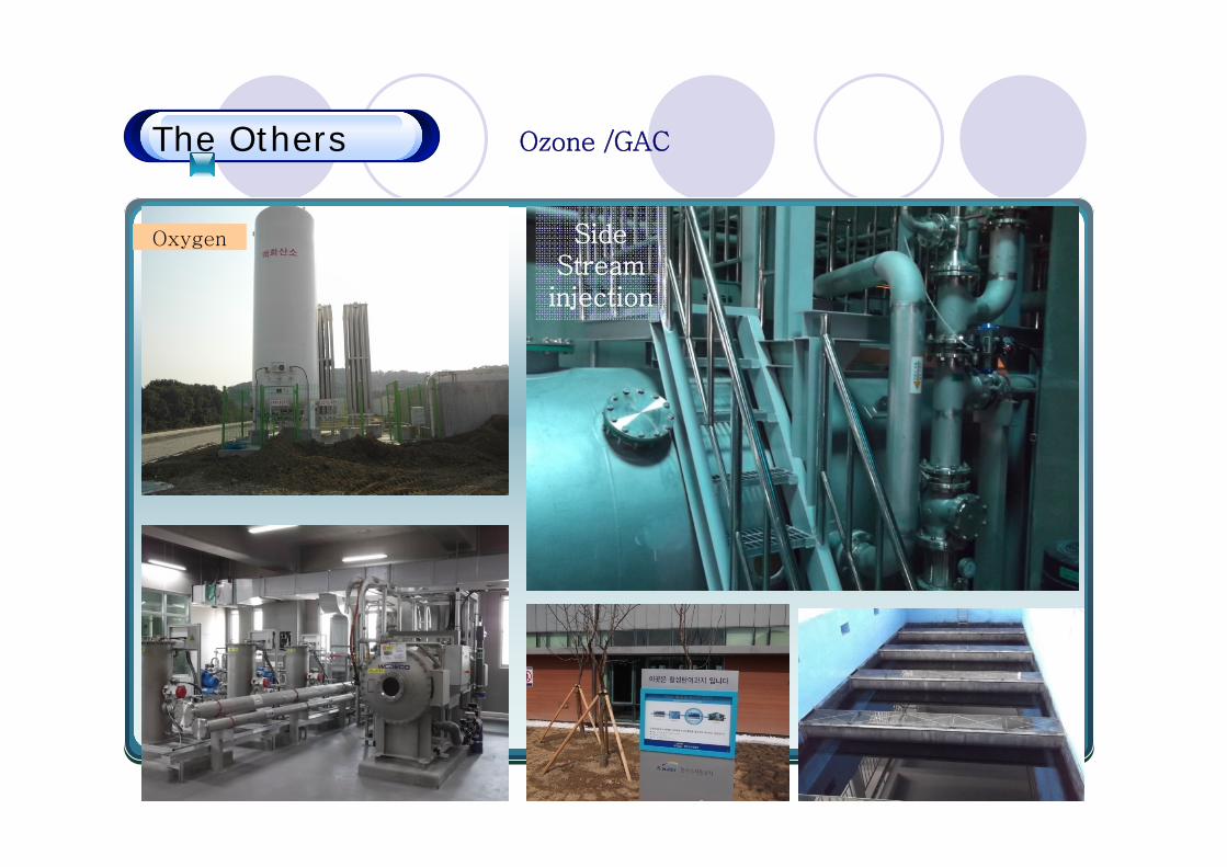
The Others Ozone /GAC
Ozone /GACOxygen Side
Streaminjection

Removal of OrganicsRemoval of Organics
Raw filtered Ozone Ozone+GAC Tap water
TOC (ppm) 2.15 1.47 1.41 0.20 0.25
Removal rate
- 31.5% 34.4% 90.6% 88.4%
Removal rate

Removal of Taste & OdorsRemoval of Taste & Odors
Treated Water
Raw Water

Average Max. Min
Ozone Dose(ppm)
0.56 1.3 0.3
Ozone DoseOzone Dose
Ozone Dose(ppm)
Geosmin Concentration (ppm)


So…Before making a decision…
Your CountryYour PeopleYour organization: Vision, Executive, Staffs, Strategy, etc.Your existing condition: Raw water, Water supply, water tariff rate…and…Your Financial !!!

Reference
Susumu Kawamura. Integrated Design and Operation of Water Treatment Facilities
http://www.safewater.org/PDFS/resourcesknowthefacts/Conventional_Water_Filtration.pdf (latest accessed
01112013)
http://water.epa.gov/learn/kids/drinkingwater/watertreatmentplant_index.cfm (latest accessed 01112013)
EPA Guidance Manual: Alternative Disinfectants and Oxidants
http://www.jwrc-net.or.jp/aswin/projects-activities/rd_files/jp-sg_symposium/2012_07_01.pdf (latest accessed
01112013)
http://www.water.ca.gov/education/images/watersupplyuse-l.jpg (latest accessed 01112013)
http://www.neatorama.com/wp-content/uploads/2009/12/water-500x287.jpg (latest accessed 01112013)
http://savethewater.org/wp-content/uploads/2012/06/Stock600-savethe-water-bottles-cost-to-the-envirement1.jpg
(latest accessed 01112013)
http://www.lenntech.com/water-quantity-faq.htm#ixzz2jNXiOLXe
(latest accessed 01112013)
http://ga.water.usgs.gov/edu/earthwherewater.html(latest accessed 01112013)

THANK YOU

1 psig(pound/square inch [gauge]) = 0.0689475728 bar = 0.689 meter1 scfm(standard cubic foot per minute) = 0.02831684659 cubic meter per minute

304 VS. 316 StainlessThe Differences Between Type 304 & Type 316 Stainless SteelTYPE 304 STAINLESS STEELType 304, with it’s chromium-nickel content and low carbon, is the most versatile and widely used of the austenitic stainless steels. Type 304 alloys are all modications of the 18% chromium, 8% nickel austenitic alloy. Applications for this group of alloys are varied and all possess somewhat similar characteristics in resistance to oxidation,corrosion, and durability. All provide ease of fabrication and cleaning, prevention of product contamination and over a variety of finishes and appearances.
GENERAL PROPERTIES – TYPE 304Type 304 stainless steels can meet a wide variety of physical requirements, making them excellent materials for applications including auto molding and trim, wheel covers,kitchen equipment, hose clamps, springs, truck bodies, exhaust manifolds, stainless atware, storage tanks, pressure vessels and piping.
TYPICAL ANALYSIS – TYPE 304Represented by ASTM-A240 AND ASME SA240.Elements by Percentage by Weight - Maximum Unless Range is Specified.C = .08 / Mn = 2.00 / P = .045 / S = .030 / Si = 1.00 / Cr = 18.00 - 20.00 / Ni = 8.00-12.00 / N = .10
RESISTANCE TO CORROSION – TYPE 304The 18% chromium, 8% nickel, provides good resistance to moderately acidic or caustic solutions. Type 304 may be considered to perform similarly in most non-severe applications. A notable exception is in the case of welding. Low carbon (304L) is the recommended alloy and provides increased resistance to intergranular corrosion.
MECHANICAL PROPERTIES OF TYPE 304 AT ROOM TEMPERATURETypical Mechanical Properties required for annealed material covered by ASTM A240.Yield Strength .2% offset = 30,000 / Ultimate Tensile Strength = 80,000 / Elongation = 50%. Hardness R = 90 max.
TYPE 316 STAINLESS STEELType 316 is an austenitic chromium-nickel stainless and heat-resisting steel with superior corrosion resistance as compared to other chromium-nickel steels when exposed to many types of chemical corrodents such as sea water, brine solutions, and the like.
GENERAL PROPERTIES – TYPE 316Type 316 alloy is a molybdenum bearing stainless steel. It has a greater resistance to chemical attack than the 304 family. Similarly, Type 316 is durable, easy-to-fabricate, clean, weld and finish.
TYPICAL ANALYSIS – TYPE 316Represented by ASTM-A240 and ASME SA240.C = .08 / Mn = 2.00 / P = .04 / S = .03 / Si = 1.00 / Cr = 16.00 - 18.00 / Ni = 10.00 - 14.00 / Mo = 2.00 - 3.00
RESISTANCE TO CORROSION – TYPE 316The addtion of 2% molybdenum makes 316 considerably more resistant to corrosion and oxidation than the 304 family of alloys.
MECHANICAL PROPERTIES OF TYPE 316 AT ROOM TEMPERATURETypical Mechanical Properties required for annealed material covered by ASTM-A240. Yield Strength .2% offset = 30,000 / Ultimate Tensile Strength = 80,000 / Elongation = 50%. Hardness R = 90 max.
Type 316 is considerably more resistant to solutions of sulfuric acid, chlorides, bromides, iodides and fatty acids at high temperature. In the manufacture of certain pharmaceuticals, stainless steels containing molybdenum are required in order to avoid excessive metallic contamination.