advanced water purification system for in situ resource ... · advanced water purification system...
TRANSCRIPT

Advanced Water Purification System for In Situ Resource Utilization
Stephen M. Anthony' National Aeronautics and Space Administration, John F. Kennedy Space Center, Florida 32899
Scott T. Jolle/ and James G. Captain3
QinetiQ North America, John F. Kennedy Space Center, Florida 32899
Abstract
Amain goal in the field of In Situ Resource Utilization is to develop technologies that produce oxygen from regolith to provide consumables to an extraterrestrial outpost. The processes developed reduce metal oxides in
the regolith to produce water, which is then electrolyzed to produce oxygen. Hydrochloric and hydrofluoric acids are byproducts of the reduction processes, which must be removed to meet electrolysis purity standards. We previously characterized Nation, a highly water selective polymeric proton-exchange membrane, as a filtration material to recover pure water from the contaminated solution. While the membranes successfully removed both acid contaminants, the removal efficiency of and water flow rate through the membranes were not sufficient to produce large volumes of electrolysis-grade water. In the present study, we investigated electrodialysis as a potential acid removal technique. Our studies have shown a rapid and significant reduction in chloride and fluoride concentrations in the feed solution, while generating a relatively small volume of concentrated waste water. Electrodialysis has shown significant promise as the primary separation technique in ISRU water purification processes.
I. Introduction The goal of In Situ Resource Utilization (ISRU) is to develop systems that allow for a long-term human presence
in space without the need for replenishment of materials from Earth. Lunar regolith is of particular interest to ISRU researchers as potential source of oxygen for fuel and life support1
•2
• Hydrogen, which has been detected in the permanently-shaded regions of craters near the lunar ~oles , can be used to reduce the metal oxides present in lunar regolith to produce water, and via electrolysis, oxygen .4.
Prior to electrolysis, the water generated as an intermediate product must be treated to remove absorbed hydrochloric and hydrofluoric acids, byproducts derived from trace amounts of fluoride and chloride present in lunar regolith5
. In terrestrial applications, removal of chloride and fluoride from water is a relatively trivial process due to the availability of consumable adsorbents, or by utilizing other processes that require frequent regeneration6
•8
. None of these processes are applicable in the lunar environment, however, where resources are scarce.
We previously studied Nation, a commercially-available sulfonated tetrafluoroethylene polymer membrane, as an ISRU filtration material because it can continuously facilitate water transport and acid rejection without the need for replacement or regeneration9
. While Nation showed promise as a filtration membrane, it was unable to remove sufficient quantities of contaminants, particularly fluoride, and would require very large membrane contact areas to generate appreciable quantities of clean water. Electrodialysis was chosen as an alternative water purification process for the present study, due to its extensive industrial pedigree and demonstrated ability to rapidly produce a clean water supply and concentrated waste brine10
-11
•
1 Aerospace Technologist, Engineering and Technology Directorate, Mail Code NE-F2. 2 Chemist, Applied Science and Technology, Mail Code ESC-55 . 3 Chemist, Applied Science and Technology, Mail Code ESC-55 .
1 American Institute of Aeronautics and Astronautics
https://ntrs.nasa.gov/search.jsp?R=20140002803 2018-06-25T05:05:54+00:00Z

Electrodialysis uses the principle of ion exchange as shown schematically ~igure 1. An electrodial:eY stack contains alternating cation and anion exchange membranes between two electrodes, with fluid-containing channels between each. Initially contaminated feed (diluent) and initially clean waste (concentrate) solutions are passed through every other chamber as direct current is applied across the electrodes. Anionic contaminants in the diluent solution diffuse across the anion exchange membrane toward the anode (positively charged electrode), while cationic contaminants diffuse across the cation exchange membrane toward the cathode (negatively charged electrode).
4j •
'8 • .r::
c3 :
The ionic species become Figure 1. Schematic representation of the electrodialysis process. trapped in the concentrate
+ + + + + .. + ..,
0 + = < + + + + + + +
Clean Water
solution, as the current directs anions toward cation exchange membranes through which they cannot diffuse, and vice-versa.
When dissolved in water, HCl and HF dissociate into their individual ionic species, i.e. H+, cr and F. As a strong acid, HCl fully dissociates into its respective ions, while HF, a weak acid, only partially dissociates in an equilibrium process. It is therefore expected that HCl will rapidly and nearly completely diffuse from the diluent to the concentrate stream, while HF will diffuse into the concentrate stream more slowly, as the gradual removal of fluoride ions will allow more HF to dissociate and be removed from the diluent stream. It is also expected that as the ion concentration in the concentrate stream increases, osmotic pressure will drive water from the diluent to the concentrate stream over time, reducing the yield of clean water. As a result, experiments focused on optimizing both the quantity of chloride and fluoride ions removed from the diluent stream, and the rapidity of ion transfer.
II. Experimental
A. Experimental Apparatus Figure 2 is an image of the apparatus used for all experiments. This small bench scale system was set up in a
fume hood using pumps to facilitate fluid flow, and polytetrafluoroethane (PTFE) diluent and concentrate reservoirs. A prefabricated stack ~sisting of 20 alternating anion and cation exchange membranes was used (EET Corporation). The mer&.nes consisted of polyamide fibers with polyethylene binder (Ralex). Anion exchange was facilitated by trimethylamine functional groups, while cation exchange was facilitated by sulfate functional groups. Two peristaltic pumps (Cole Parmer, Model 7553-70) were used to circulate the diluent and concentrate streams between the PTFE reservoir and electrodialysis stack, and one metering pump (Valcor Scientific, Model SVl 04) was used to circulate an electrode buffer solution to maintain consistent current throughout the process. Cole Parmer Bev-A-Line IV was used due to the corrosive nature of the contaminants. Direct current was applied using a GW Instek GPS-3303 power supply.
2 American Institute of Aeronautics and Astronautics
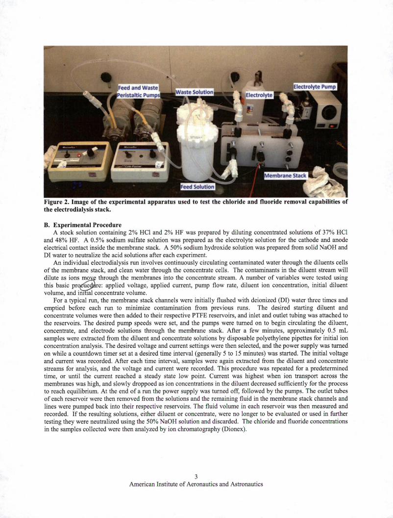
Figure 2. Image of the experimental apparatus used to test the chloride and fluoride removal capabilities of the electrodialysis stack.
B. Experimental Procedure A stock solution containing 2% HCl and 2% HF was prepared by diluting concentrated solutions of 37% HCl
and 48% HF. A 0.5% sodium sulfate solution was prepared as the electrolyte solution for the cathode and anode electrical contact inside the membrane stack. A 50% sodium hydroxide solution was prepared from solid NaOH and DI water to neutralize the acid solutions after each experiment.
An individual electrodialysis run involves continuously circulating contaminated water through the diluents cells of the membrane stack, and clean water through the concentrate cells. The contaminants in the diluent stream will dilute as ions~o through the membranes into the concentrate stream. A number of variables were tested using this basic pr e e: applied voltage, applied current, pump flow rate, diluent ion concentration, initial diluent volume, and im 1al concentrate volume.
For a typical run, the membrane stack channels were initially flushed with deionized (DI) water three times and emptied before each run to minimize contamination from previous runs. The desired starting diluent and concentrate volumes were then added to their respective PTFE reservoirs, and inlet and outlet tubing was attached to the reservoirs. The desired pump speeds were set, and the pumps were turned on to begin circulating the diluent, concentrate, and electrode solutions through the membrane stack. After a few minutes, approximately 0.5 mL samples were extracted from the diluent and concentrate solutions by disposable polyethylene pipettes for initial ion concentration analysis. The desired voltage and current settings were then selected, and the power supply was turned on while a countdown timer set at a desired time interval (generally 5 to 15 minutes) was started. The initial voltage and current was recorded. After each time interval, samples were again extracted from the diluent and concentrate streams for analysis, and the voltage and current were recorded. This procedure was repeated for a predetermined time, or until the current reached a steady state low point. Current was highest when ion transport across the membranes was high, and slowly droppoed as ion concentrations in the diluent decreased sufficiently for the process to reach equilibrium. At the end of a run the power supply was turned off, followed by the pumps. The outlet tubes of each reservoir were then removed from the solutions and the remaining fluid in the membrane stack channels and lines were pumped back into their respective reservoirs. The fluid volume in each reservoir was then measured and recorded. If the resulting solutions, either diluent or concentrate, were no longer to be evaluated or used in further testing they were neutralized using the 50% NaOH solution and discarded. The chloride and fluoride concentrations in the samples collected were then analyzed by ion chromatography (Dionex).
3 American Institute of Aeronautics and Astronautics
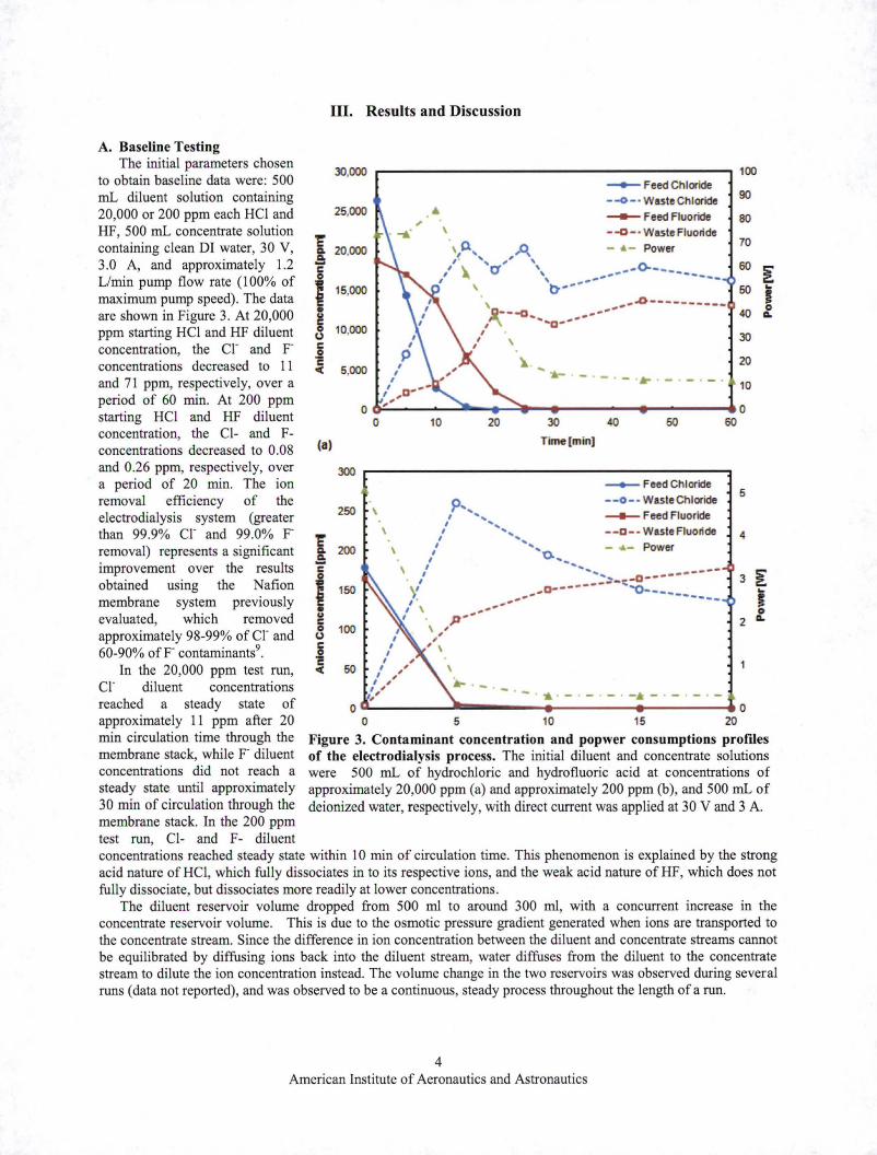
A. Baseline Testing The initial parameters chosen
to obtain baseline data were: 500 mL diluent solution containing 20,000 or 200 ppm each HCl and HF, 500 mL concentrate solution containing clean DI water, 30 V, 3.0 A, and approximately 1.2 L/min pump flow rate (1 00% of maximum pump speed). The data are shown in Figure 3. At 20,000 ppm starting HCl and HF diluent concentration, the cr and pconcentrations decreased to 11 and 71 ppm, respectively, over a period of 60 min. At 200 ppm starting HCl and HF diluent concentration, the Cl- and Fconcentrations decreased to 0.08 and 0.26 ppm, respectively, over a period of 20 min. The ion removal efficiency of the electrodialysis system (greater than 99.9% cr and 99.0% premoval) represents a significant improvement over the results obtained using the Nation membrane system previously evaluated, which removed approximately 98-99% of cr and 60-90% ofF contaminants9
.
In the 20,000 ppm test run, cr diluent concentrations reached a steady state of approximately 11 ppm after 20 min circulation time through the membrane stack, while F diluent concentrations did not reach a steady state until approximately 30 min of circulation through the membrane stack. In the 200 ppm test run, Cl- and F- diluent
III. Results and Discussion
'E' Q.
.!!: ~
I • & (,) c .2 c "(
{a)
30,000
25,000
20,000
15,000
10,000
5,000
0
300
250
150
100
50
~------------------------------------~ 100
0
\
\
\
- Feed Chloride --o-· w aste Chloride
- Feed Fluoride \ --a-· Waste Fluoride
,p., A - •- Power , ', ~' ' II \. r/ ', .,.~.,,_()-____ ., __
I ~ \ ,.,..- --\ b-~~ .. . ' ... ..o.---------... ~--a ........ -
, , I ' "" ........ '0 ___ _
\
- ·-·-···-·-·-
10 20 30 40 50
Time[minl
- Feed Chloride --0-· Waste Chloride p .... ,,
I " I .. , I .. ,
,' ',, ,' .. ~ ....
\ I ........ , .---11 .... ,~---o-------
\ 1 a.------- .... '()-~ .......... ---------1 .. -
I \ ,. .. .-I p-..
\ ,'
~Feed Fluoride
--a-- Waste Fluoride
- •- Power
, , \
-·-
90
80
70
60 ~ 50 ..
! 40 Q.
30
20
10
5
4
oG---------~--------~--------~--------~ 0 0 5 10 15 20
Figure 3. Contaminant concentration and popwer consumptions profiles of the electrodialysis process. The initial diluent and concentrate solutions were 500 mL of hydrochloric and hydrofluoric acid at concentrations of approximately 20,000 ppm (a) and approximately 200 ppm (b), and 500 mL of deionized water, respectively, with direct current was applied at 30 V and 3 A.
concentrations reached steady state within 10 min of circulation time. This phenomenon is explained by the strong acid nature of HCl, which fully dissociates in to its respective ions, and the weak acid nature of HF, which does not fully dissociate, but dissociates more readily at lower concentrations.
The diluent reservoir volume dropped from 500 ml to around 300 ml, with a concurrent increase in the concentrate reservoir volume. This is due to the osmotic pressure gradient generated when ions are transported to the concentrate stream. Since the difference in ion concentration between the diluent and concentrate streams cannot be equilibrated by diffusing ions back into the diluent stream, water diffuses from the diluent to the concentrate stream to dilute the ion concentration instead. The volume change in the two reservoirs was observed during several runs (data not reported), and was observed to be a continuous, steady process throughout the length of a run.
4 American Institute of Aeronautics and Astronautics

The drop in current values over time eventually reached a near steady state as the number of ions available for transport dropped. Monitoring the current level proved to be a valuable tool in signaling when a particular run had reached a steady state.
B. Variable Matrix Testing The initial concentrate volume, pump speed, applied voltage, and applied current were then changed to
determine which parameters had the greatest effect on contaminant removal. The initial diluent volume was held constant at 500 mL, as was the initial diluent acid concentration of20,000 ppm each HCl and HF. Table 1 highlights the results obtained when a single process variable was changed. The minimum cr and F diluent concentrations, as well as the final diluent and concentrate volumes are listed.
Table 1: Evaluation of electrodialysis process variables. In each case, the initial diluents solution contained 500 mL f 20 000 h h dr hi . d h dr fl . . d 0
' 1pm eac ty< oc one an ty~ o uonc act s.
Init. Cone. Pump Applied Applied Final F- Fianl cr
Final Dil. Final
Vol. (mL) Speed (% Voltage Current Cone. Cone.
Vol. (mL) Cone. Vol.
of max) M (A) (ppm) (ppm) (mL) 500 100 30 3.0 71 11 295 685 250 100 30 3.0 167 22 335 400 130 100 30 3.0 290 25 305 310 0 100 30 3.0 550 23 170 290
500 50 30 3.0 158 20 300 700 500 20 30 3.0 71 8.6 280 650 500 < 10 30 3.0 14,500 13,700 500 510 500 100 15 3.0 1,170 47 325 675 500 100 60 3.0 26 2.8 350 640 500 100 30 1.5 132 26 355 610 500 100 30 6.0 79 9.8 365 685
Ion transport decreased with decreasing initial concentrate volume. This is most likely due to higher concentration gradients inhibiting further ion transport at lower initial concentrate volumes. The lowest fluoride and chloride concentrations were achieved by applying a 60 V potential difference across the electrodes. This voltage represented the maximum voltage possible with the power supply used in this testing. The ion exchange membrane manufacturer recommends voltages no higher than 80 V, so no efforts were made to test at higher voltages.
Ion exchange appe~to nearly stop at extremely low flow rates. The pump speeds were able to be lowered to 20% of maximum without significantly affecting ion transfer from the diluent to the concentrate streams, but setting the pumps at their lowest possible speed, little to no ion exchange occurred. It is possible that at such low flow rates, there is not enough turbulence generated in the membrane channels to allow most of the ions to come in contact with the membranes. Relative proximity to the membranes is necessary for ions to be attracted by the oppositely-charged membrane functional groups.
C. ISRU Scenario Testing The previous results showed that while generating electrolysis-grade water was possible at lower starting
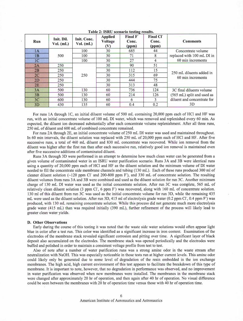
contaminant concentrations, a single pass through the electrodialysis stack was not sufficient at higher contaminant concentrations . Several tests were run in which periodic changes were made to either the feed or waste stream volumes. These runs were performed in an attempt to identify a multi-step operational concept for an actual ISRU scenario. Table 2 details the results obtained while making these periodic changes. For all runs, the pumps were set to maximum speed, and 3 A was applied across the electrodes.
5 American Institute of Aeronautics and Astronautics
a e : T bl 2 ISRU seenano es ng resu s. . t ti It
Init. Dil. lnit. Cone. Applied Final F- Final Cr
Run Vol. (mL) Vol. (mL)
Voltage Cone. Cone. Comments (\'} (ppm) (ppm)
1A 100 30 685 44 Concentrate volume 1B 500 100 30 71 8 replaced with 100 mL DI in lC 100 30 27 4 60 min increments 2A 250 30 90 51 2B 250 30 112 15
250 mL diluents added in 2C 250 250 30 315 69 20 250 30 444 75
60 min increments
2E 250 30 313 48 3A 500 130 60 736 124 3C final diluents volume 3B 500 130 60 214 126 (565 mL) split and used as 3C 600 130 60 6 3 diluent and concentrate for 30 430 135 60 0.4 0.2 30
For runs 1A through 1 C, an initial diluent volume of 500 mL containing 20,000 ppm each of HCl and HF was run, with an initial concentrate volume of 100 mL 01 water, which was removed and replenished every 60 min. As expected, the diluent ion decreased substantially after each concentrate volume replenishment. After all three runs, 250 inL of diluent and 600 mL of combined concentrate remained.
For runs 2A through 2E, an initial concentrate volume of250 mL DI water was used and maintained throughout. In 60 min intervals, the diluent solution was replaced with 250 mL of 20,000 ppm each of HCl and HF. After five successive runs, a total of 460 mL diluent and 830 mL concentrate was recovered. While ion removal from the diluent was higher after the first run than after each successive run, relatively good ion removal is maintained even after five successive additions of contaminated diluent.
Runs 3A through 3D were performed in an attempt to determine how much clean water can be generated from a given volume of contaminated water in an ISRU water purification scenario. Runs 3A and 3B were identical runs using a quantity of 20,000 ppm each of HCl and HF as the diluent solution and the minimum volume of DI water needed to fill the concentrate side membrane channels and tubing (130 mL). Each of these runs produced 300 ml of cleaner diluent solution (- 120 ppm cr and 200-800 ppm F), and 330 mL of concentrate solution. The resulting diluent volumes from runs 3A and 3B were combined and used as the diluent solution for run 3C. Another minimum charge of 130 mL DI water was used as the initial concentrate solution. After run 3C was complete, 565 mL of relatively clean diluent solution (3 ppm cr, 6 ppm F) was recovered, along with 160 mL of concentrate solution. 130 ml of this diluent from run 3C was used as the initial concentrate volume for run 3D, while the remaining 435 mL were used as the diluent solution. After run 3D, 415 ml of electrolysis grade water (0.2 ppm cr, 0.4 ppm F) was produced, with 130 mL remaining concentrate solution. While this process did not generate much more electrolysis grade water (415 mL) than was required initially (390 mL), further refinement of the process will likely lead to greater clean water yields.
D. Other Observations Early during the course of this testing it was noted that the waste side water solutions would often appear light
blue in color after a test run. This color was identified as a significant increase in iron content. Examination of the electrodes of the membrane stack revealed significant corrosion and pitting over time. A significant layer of black deposit also accumulated on the electrodes. The membrane stack was opened periodically and the electrodes were buffed and polished in order to maintain a consistent voltage profile from test to test.
Also of note after a number of water purification runs was a strong amine odor in the waste stream after neutralization with NaOH. This was especially noticeable in those tests run at higher current levels. This amine odor could likely only be generated due to some level of degradation of the resin embedded in the ion exchange membranes. The high acid, high current environment of this test appears to facilitate the breakdown of this type of membrane. It is important to note, however, that no degradation in performance was observed, and no improvement in water purification was observed when new membranes were installed. The membranes in the membrane stack were changed after approximately 20 hr of operation, and then again after 40 hr of operation. No visual difference could be seen between the membranes with 20 hr of operation time versus those with 40 hr of operation time.
6 American Institute of Aeronautics and Astronautics

IV. Conclusion This project has successfully demonstrated the purification of high ion content water via the use of
electrodialysis. The knowledge gained during the evaluation of this process indicates that electrodialysis represents an excellent choice as a primary water purification method in long duration exploration missions to locations such as the Moon or Mars. Although this work has resulted in excellent progress towards developing a method that can be used to purify water streams produced from extraterrestrial sources, much work needs to be done to establish the best electrodialysis system for use in this environment. Further effort will need to be made to set up and evaluate an automated system that can be operated in tandem with an ISRU water generation process.
Acknowledgments The authors thank the Kennedy Space Center Innovation Fund, and the NASA !dependent Research &
Technology Development and Core Technical Capabilities programs for their support of this work.
References 1Torasso, A. , "ISRU technologies and sustainable space exploration," AIAA 58'h International Astronautical Congress, 2007,
pp. 7115-7127. 2Vallerani, E., "ISRU: Perspectives for lunar development," AIAA 57'h International Astronautical Congress, 2006, pp. 1748-
1762. 3Hedge, U., Balasubramaniam, R. , Gokoglu, S., "Analysis of thermal and reaction times for hydrogen reduction of lunar
regolith," Space Technology and Applications International Forum, 2008, pp. 195-202. 4Maurice, S., Feldman, W.C., Lawrence, D.J., Gasnault, 0 ., Elphic, R.C., Chevrel, S. , "Distribution of hydrogen at the
surface of the moon," Lunar and Planetary Science, Vol. 34,2003, p. 1867. 5Schrader, C.M., Rickman, D.L., McLemore, C.A., Fikes, J.C. , "Lunar Regolith Simulant User' s Guide," NASA TM-2010-
216446, 2010. 6Dou, X., Zhang, Y., Wang, H. , Wang, T., Wang, Y., "Performance of granular zirconium-iron oxide in the removal of
fluoride from drinking water," Water Research, Vol. 45, 2011, pp. 3571-3578. 7Lu, N.C., Liu, J.C., "Removal of phosphate and fluoride fr.om wastewater by a hybrid precipitation-micro.filtration process,"
Separation and Purification Technology, Vol. 74, 2010, pp. 329-335. 8Unnkrishnan, E.K., Kumar, S.D., Maiti, B., "Permeation of inorganic anions through Nation ionomer membrane," Journal
of Membrane Science, Vol. 137, 1997, pp. 133-137. 9 Anthony, S.M., Santiago-Maldonado, E., Captain, J.G., Pawate, A.S., Kenis, P.J.A., "Contaminant removal from oxygen
production systems for in situ resource utilization," AlAA SPACE 2012 Conference and Exposition , AIAA, 2012-5167. 10Arda, M., Orban, E., Arar, 0 ., Yuksel, M., Kabay, N. , "Removal of fluoride from geothermal water by electrodialysis,"
Separation Science and Technology, Vol. 44, 2009, pp. 841-853 . 11Jones, C.P., Pierce, A.M., Roberts, B.R. , "Deionization: the use of EDI technology to recycle HR acid wastes from
scrubbers and thermal treatment units," Ultrapure Water, July/August 2006, pp. 34-38.
7 American Institute of Aeronautics and Astronautics