advanced turbomachinery methods · 2012-08-21 · © 2011 ansys, inc. september 14, 2011 1 advanced...
TRANSCRIPT

© 2011 ANSYS, Inc. September 14, 2011
1
Advanced Turbomachinery Methods
Brad Hutchinson
ANSYS, Inc. Industry Marketing

© 2011 ANSYS, Inc. September 14, 2011
2
1. Turbomachinery challenges
2. ANSYS TurboSystem
3. Blade row fluid dynamics solution methods
– Available methods
– Description of the ANSYS Transformation methods
4. Transient Blade Row applications
5. Other ANSYS blade row design tools
6. Summary
Presentation Overview
© 2011 ANSYS, Inc. September 14, 2011
3
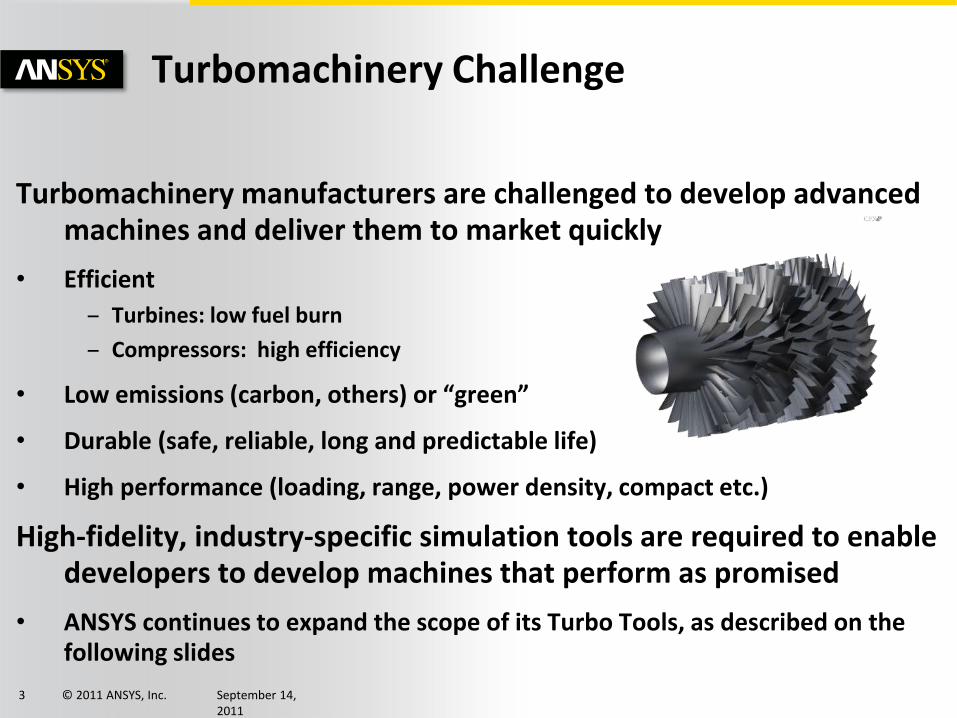
Turbomachinery manufacturers are challenged to develop advanced machines and deliver them to market quickly
• Efficient
– Turbines: low fuel burn
– Compressors: high efficiency
• Low emissions (carbon, others) or “green”
• Durable (safe, reliable, long and predictable life)
• High performance (loading, range, power density, compact etc.)
High-fidelity, industry-specific simulation tools are required to enable developers to develop machines that perform as promised
• ANSYS continues to expand the scope of its Turbo Tools, as described on the following slides
Turbomachinery Challenge

© 2011 ANSYS, Inc. September 14, 2011
4
ANSYS TurboSystem
Complete turbomachinery design and analysis in ANSYS Workbench • Geometry
• Throughflow
• Meshing
• CFD
• Thermal
• Combustion
• Structural mechanics
• Rotordynamics
• Post-processing
• Optimization
This presentation will focus on ANSYS blade row fluid dynamics tools

© 2011 ANSYS, Inc. September 14, 2011
5
1. Turbomachinery challenges
2. ANSYS TurboSystem
3. Blade row fluid dynamics solution methods
– Available methods
– Description of the ANSYS Transformation methods
4. Transient Blade Row applications
5. Other ANSYS blade row design tools
6. Summary
Presentation Overview

© 2011 ANSYS, Inc. September 14, 2011
6
Stage (Mixing-Plane)
Frozen Rotor
Transient Rotor/ Stator
Blade Row Methods
Steady Methods Single (or few) blade passages per row
Blade Row Fluid Dynamics: Steady
+ Proven, industry-standard workhorse tools + Fast and efficient + Good at design point - Do not account for unsteady phenomena

© 2011 ANSYS, Inc. September 14, 2011
7
Stage (Mixing-Plane)
Frozen Rotor
Transient Rotor/ Stator
Blade Row Methods
Blade Row Fluid Dynamics: Transient
+ Accurately captures unsteady interactions - Unequal pitch dictates full or partial wheel modeling - Requires large computing resource
S2
S1
R2
R1
ROTOR
STATOR
VR PR PS
unequal pitch
Phase-shifted boundaries a consequence of pitch change
Transient Method Full Domain Modeling

© 2011 ANSYS, Inc. September 14, 2011
8
Blade Row Fluid Dynamics: Transient
• Problem: How to obtain the full-wheel transient solution, but at low cost?
• Solution: The ANSYS TBR Transformation family of methods
+ New models minimize number of simulated passages, providing enormous efficiency gains and reduced infrastructure requirements

© 2011 ANSYS, Inc. September 14, 2011
9
Stage (Mixing-Plane)
Frozen Rotor
Transient Rotor/ Stator
Blade Row Methods
Blade Row Fluid Dynamics Solutions
Transient Method Full Domain Modeling
Steady Methods Single (or few) blade passages per row
Transient with
Pitch Change
TBR Transformation Methods
Profile Transformation
Time Transformation
Fourier Transformation
Harmonic Transformation
New
Existing Transient methods with pitch change
Single or few blade passages

© 2011 ANSYS, Inc. September 14, 2011
10
• Performs an interface profile transformation (stretching) • Maintains true blade geometry
• Accuracy increases as ensemble pitch ratio approaches unity
• Efficient and fast
• Available in CFX for many years
S2
S1
R2
R1
ROTOR STATOR
VR PR PS
PR PS
The ANSYS
TBR Transformation Methods Fast Blade Row Solutions
Profile Transformation Method

© 2011 ANSYS, Inc. September 14, 2011
11
• Transforms equations so that instantaneous periodicity applies
• Fast, low memory – Fully implicit + turbulent (unlike earlier methods)
– Ideal for inlet disturbance or single stage
• R14: released for single disturbance
– R14 (beta): combine with PT or Stage
S2
S1
R2
R1
ROTOR STATOR
VR PR PS
Pr
T,
Vr
PrPsT
0Y
G
X
E
t
Q
0'''
)(
Y
G
X
E
t
GQ
Yt't
Y'Y
X'X
Based on “Time-Inclining” (Giles, 1988)
The ANSYS
TBR Transformation Methods Fast Blade Row Solutions
Time Transformation Method

© 2011 ANSYS, Inc. September 14, 2011
12
• Fourier Series reconstructs solution on periodic/interface boundaries
• Efficient data storage
• No restriction on pitch-ratio/compressibility
• R14: released for inlet disturbance only
– R14 (beta): single stage
– Future: multiple perturbations/stages Based on L. He (1989) and Gerolymos et al. (2002)
The ANSYS
TBR Transformation Methods Fast Blade Row Solutions
Fourier Transformation Method
Sampling plane (GGI)
N
Nk
tkj
keAt )()( )( Tt
)( Tt
Accumulation of Fourier coefficients
k
R S
Solution Reconstruction
M
Ml
N
Nk
ltkj
lk eAt )(
,),(
© 2011 ANSYS, Inc. September 14, 2011
13
1. Turbomachinery challenges
2. ANSYS TurboSystem
3. Blade row fluid dynamics solution methods
– Available methods
– Description of the ANSYS Transformation methods
4. Transient Blade Row applications
5. Other ANSYS blade row design tools
6. Summary
Presentation Overview

© 2011 ANSYS, Inc. September 14, 2011
14
# of nodes for one stator + one rotor passage
LPT – Description (more details in GT2011- 46635)
• Low pressure turbine stage designed by PCA Engineers (UK)
• Typical of stages sometimes used in the low pressure section of an aircraft engine
• High loading
– Work coefficient (ΔH/U2) = 2.8
• High lift coefficient
– Rotor Zweifel coefficient = 1.35
• 88 stators : 76 rotors
– Quarter wheel periodicity
• Flared casing
• Shrouded rotor blades
• No tip gap or leakage flows
• Hexahedral meshes from ANSYS TurboGrid
Coarse: 478K
Medium: 1.2M
Fine: 2.3M
© 2011 ANSYS, Inc. September 14, 2011
15
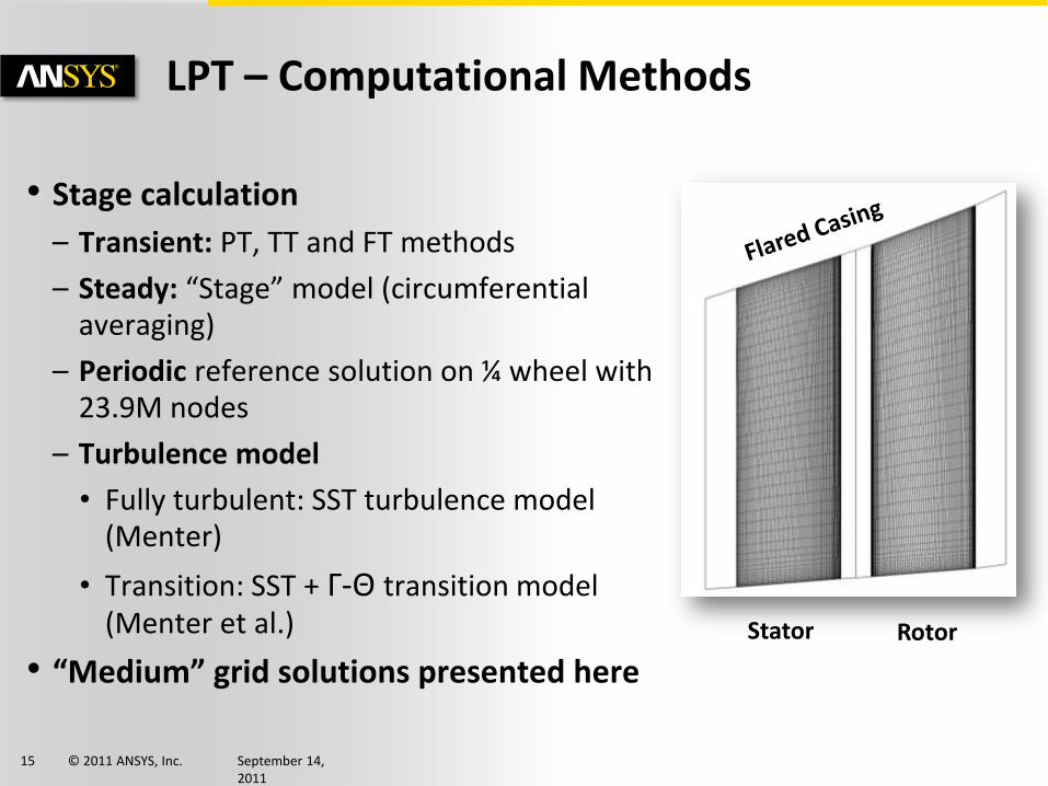
• Stage calculation
– Transient: PT, TT and FT methods
– Steady: “Stage” model (circumferential averaging)
– Periodic reference solution on ¼ wheel with 23.9M nodes
– Turbulence model
• Fully turbulent: SST turbulence model (Menter)
• Transition: SST + Γ-Θ transition model (Menter et al.)
• “Medium” grid solutions presented here
LPT – Computational Methods
Stator Rotor
© 2011 ANSYS, Inc. September 14, 2011
16
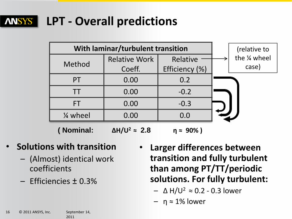
LPT - Overall predictions
With laminar/turbulent transition
Method Relative Work
Coeff. Relative
Efficiency (%)
PT 0.00 0.2
TT 0.00 -0.2
FT 0.00 -0.3
¼ wheel 0.00 0.0
• Solutions with transition – (Almost) identical work
coefficients
– Efficiencies ± 0.3%
• Larger differences between transition and fully turbulent than among PT/TT/periodic solutions. For fully turbulent: – Δ H/U2 ≈ 0.2 - 0.3 lower
– η ≈ 1% lower
( Nominal: ΔH/U2 ≈ 2.8 η ≈ 90% )
(relative to the ¼ wheel
case)

© 2011 ANSYS, Inc. September 14, 2011
17
LPT - Flow details (1)
Instantaneous midspan entropy almost identical (with transition)
Time-averaged mid-span Mach # almost identical (no transition)
TT
PT
Reference
Reference TT
© 2011 ANSYS, Inc. September 14, 2011
18
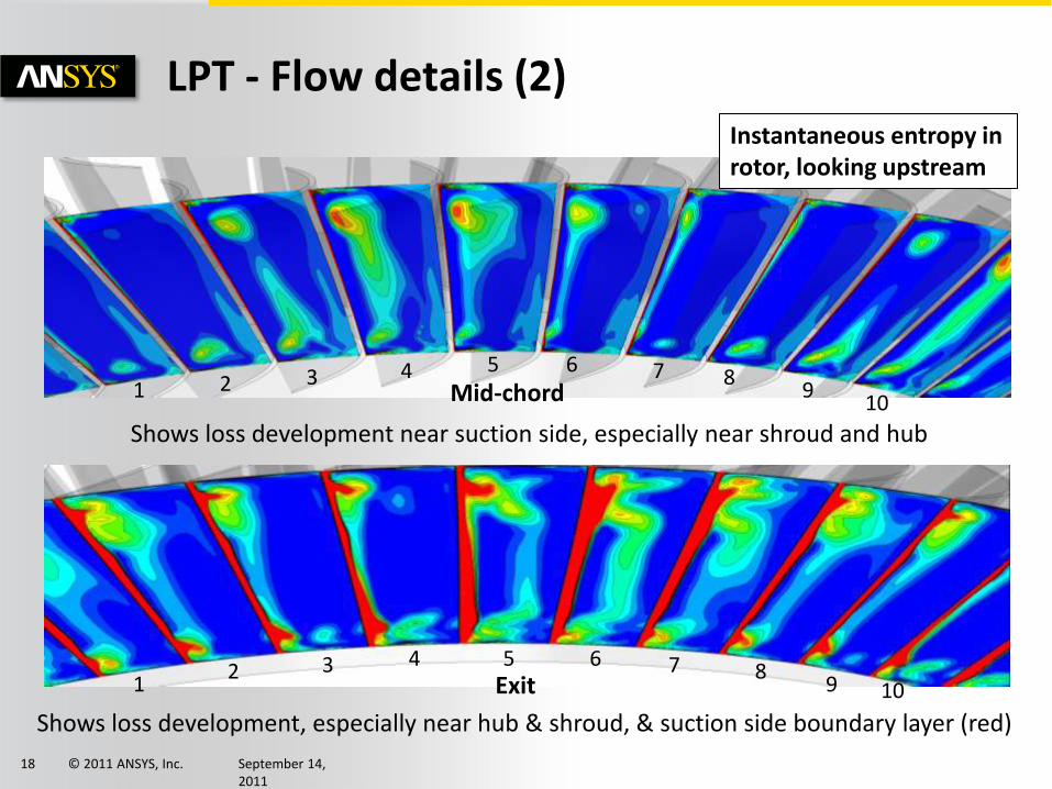
LPT - Flow details (2)
1 2 3 4 5 6 7 8 9
10 Mid-chord
1 2 3 4 5 6 7 8
9 10 Exit
Instantaneous entropy in rotor, looking upstream
Shows loss development, especially near hub & shroud, & suction side boundary layer (red)
Shows loss development near suction side, especially near shroud and hub

© 2011 ANSYS, Inc. September 14, 2011
19
LPT - Computational Effort
Method Stator/Rotor
Passages Relative effort
Stage (steady) 1/1 1.0
PT 1/1 22.0
TT 1/1 36.7
FT 2/2 48.0
¼ wheel 22/19 440.0
• Transformation methods – Require 20 to 50 times the effort of steady solutions
– Require about one order magnitude less effort than periodic
solution (¼ wheel, reference solution), and machine/disk requirements an order of magnitude lower

© 2011 ANSYS, Inc. September 14, 2011
20
R1
S1 R2
S2
R3
S3
R4 S4
IG
Modified Hannover Axial Compressor
Beta at R14: combined usage of PT and TT Courtesy of TFD Hannover

© 2011 ANSYS, Inc. September 14, 2011
21
IGV R1 S1 R2 S2
PT PT TT TT
Time Transformation
PT PT TT
TT Reference (1/4 wheel)
Courtesy of TFD Hannover
Modified Hannover Axial Compressor: 2Pt + 2TT solution .vs. full domain solution

© 2011 ANSYS, Inc. September 14, 2011
22
1. Turbomachinery challenges
2. ANSYS TurboSystem
3. Blade row fluid dynamics solution methods
– Available methods
– Description of the ANSYS Transformation methods
4. Transient Blade Row applications
5. Other ANSYS blade row design tools
6. Summary
Presentation Overview
© 2011 ANSYS, Inc. September 14, 2011
23
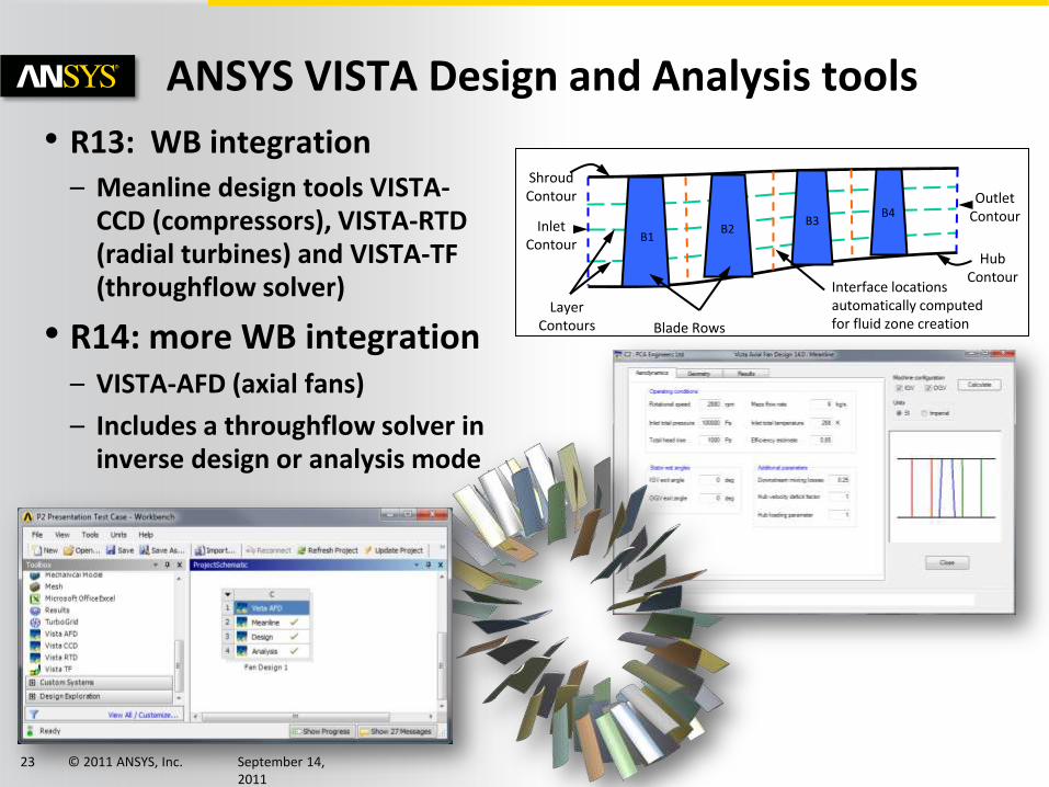
Blade Rows
Interface locations automatically computed for fluid zone creation
B1 B2
B3 B4
Inlet Contour
Outlet Contour
Hub Contour
Shroud Contour
Layer Contours
• R13: WB integration – Meanline design tools VISTA-
CCD (compressors), VISTA-RTD (radial turbines) and VISTA-TF (throughflow solver)
• R14: more WB integration – VISTA-AFD (axial fans)
– Includes a throughflow solver in inverse design or analysis mode
ANSYS VISTA Design and Analysis tools

© 2011 ANSYS, Inc. September 14, 2011
24
• R13: Airfoil Design Mode – Enabled axial turbo design
– Also: auxiliary view plots, blade parameterization in WB (for DOE)
• R14: Arbitrary flow path layers – Using sketch curves, layers don’t
need to be at constant span
ANSYS BladeModeler
- Improved workflow
- Camberline and airfoil design modes more consistent
- Auxiliary view for blade/flow path curvature
© 2011 ANSYS, Inc. September 14, 2011
25
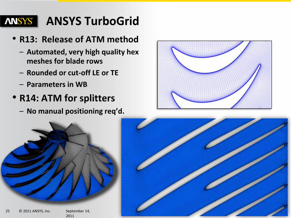
• R13: Release of ATM method – Automated, very high quality hex
meshes for blade rows
– Rounded or cut-off LE or TE
– Parameters in WB
• R14: ATM for splitters – No manual positioning req’d.
ANSYS TurboGrid

© 2011 ANSYS, Inc. September 14, 2011
26
• R14: New templates added to improve mesh resolution near rounded leading and trailing edges
ANSYS TurboGrid
• R14: “Double-herringbone” template added to improve mesh resolution for cut-off blades with lower blade angles

© 2011 ANSYS, Inc. September 14, 2011
27
1. Turbomachinery challenges
2. ANSYS TurboSystem
3. Blade row fluid dynamics solution methods
– Available methods
– Description of the ANSYS Transformation methods
4. Transient Blade Row applications
5. Other ANSYS blade row design tools
6. Summary
Presentation Overview

© 2011 ANSYS, Inc. September 14, 2011
28
ANSYS is advancing the availability of high-fidelity, industry-specific simulation tools which assist in the development of advanced turbomachines that are
• Efficient
• “Green”
• Durable
• High performance
Significant advances, to be delivered at ANSYS R14, in transient blade row simulation and blade row design tools have been presented
ANSYS plans to continue with significant advances to its turbomachinery-specific tools beyond R14
Summary