advanced traffic management system: real-time network...
TRANSCRIPT

TRANSPO RTATION RESEA RCH RECORD 1358 13
Advanced Traffic Management System: Real-Time Network Traffic Simulation Methodology with a Massively Parallel Computing Architecture
THANAVAT }UNCHAYA, GANG-LEN CHANG, AND ALBERTO SANTIAGO
The advent of paralle l computing architectures presents an opportunity for lranspon a tion professionals 1 imulate a large- ca le tra ffic ne twork with sufficienily fa t response time for rea l-time opcrarion . Howeve r, ii neccssira tc ·.a fundamental change in the modeling algorithm LO tuke full adva ntage of parallel computing. • uch a methodology t imulare tra ffic n twork with the Connection Machine , a massively parallel computer, is described . The basic parallel computing architectures are introdu ed , along with a list of commercia lly available parallel comput ers. This is followed by an in-depth presentation of the proposed simulation methodology with a massively paralle l computer. The propo ed traffic simulation model ha. an inherent path-proces ing capabilit y to represent drivers ' roure choice behavior at the individualvehicle level. It has been implemented on the Connection Machine with 16,384 proces ors. Preliminary simulation experiments indicate that massively parallel computers are a practicable alternarive for achieving real-time application. The exp riment shows that the Connection Machine with 16k proces. ors can simulate 32,000 vehicles for 30 min at 2-sec intervals within 2 min of running time .
Many metropolitan areas around the world face serious congestion problems that threaten to deteriorate the quality of life and increase air pollution . It was estimated that traffic congestion in 1987 accounted for more than 2 billion vehicle-hr of delay and 2.2 billion gal of excessive fuel consumption in the United States (1). In the next decade, the unavoidable dramatic increase in travel demand coupled with the diminishing construction of new transportation facilities will certainly worsen the traffic condition unless innovative congestionrelief methods can be developed and implemented in time .
One area that seems most promising in alleviating congestion is the development of intelligent vehicle-highway systems (IVHSs), specifically in the form of advanced traveler information systems (ATISs) and advanced traffic management systems (ATMSs) . Significant improvements in mobility, highway safety, and productivity can thus be achieved through integrated applications of advanced technologies to surveillance, communications, route guidance, and control process (2). Research is being undertaken in such areas as adaptive traffic control, incident detection , real-time traffic assignment , and corridor optimization. Successful implementation
T. Junchaya, G. L. Chang, Department of Civil Engineering, University of Maryland , College Park , Md. 20742. A. Santiago, Federal Highway Administration, McLean, Va . 22101.
of these ATMS developments would ensure optimal networkwise performance.
The anticipated benefits of these control methods depend on the complex interactions among principal traffic system components . These systems include driver behavior, level of congestion, dynamic nature of traffic patterns , and the network's geometric configuration . It is crucial to the design of these strategies that a comprehensive understanding of the complex interrelations between these key system components be established . Because it is often difficult for theoretical formulations to take all such complexities into account , traffic simulation offers the unique capability to conduct performance evaluations . In addition, an effective on-line simulation model would enable the ATMS control center to project promptly future traffic patterns considering any previously implemented strategies in a real-time operating environment. A graphical illustration of a traffic simulation model's function in ATIS-ATMS implementation is presented in Figure 1.
Such a real-time network traffic simulation model is required to have at least the following features: (a) a realistic representation of traffic characteristics and geometric configurations; (b) the capability to simulate both freeway and surface street networks at different levels of detail; and (c) a path-processing capability to represent drivers' route choice behavior at the individual-vehicle level. In addition, in order to be operational in a re al-time basis, the software design must be efficient and well structured and maximize the utility of the hosting hardware . A comprehensive literature review clearly indicated that none of the existing simulation and assignment models fully meets these functional requirements. A detailed discussion in thi s regard can be found elsewhere (3) .
In terms of providing sufficiently fast response to simulate a large-scale network, the use of advanced parallel computing architectures appears to be one of the most promising methods . However, adoption of this posture may require a fundamental change in the modeling algorithm. This cannot be achieved through the existing traffic simulation methodologies developed mainly for conventional computing machines .
The objective of this paper is to introduce a real-time traffic network simulation methodology that fully utilizes the capability of massively parallel machines. Some basic parallel computing architectures are introduced along with a list of

14
FREEWAY
CONTROL
SYSTEM
TRANSPORTATION RESEARCH RECORD 1358
TRAFFIC
SIGNAL
SYSTEM
CENTRAL CONTROLLER Ramp Control
Freeway Condition Real·Ume Traffic SlmulaUon Model Urban Street Condition
FREEWAY
INFORMATION
SYSTEM
0-D Lt>c:ation TravelTlma
Guidance
lnfonnatlon
URBAN STREET
INFORMATION
SYSTEM
FIGURE 1 ATIS-ATMS system component.
commercially available parallel computers. There is also an in-depth presentation of the proposed simulation methodology with a massively parallel computer, specifically the Connection Machine , and some empirical results are given . Ongoing research activities and potential integration with related studies are also presented.
REVIEW OF PARALLEL PROCESSING METHODOLOGY AND ARCHITECTURE
Prodigious advances in computer architectures and capabilities have taken place in the past two decades. New technologies and innovative architectures will continue to appear in addition to the already bewildering array of configurations. However, it has become apparent to most researchers that the most promising long-term approach to achieve affordable, accessible supercomputing is parallel processing.
Parallel processing has been defined as follows:
Pa ra llel processing is 1111 elTicicnL form of infornrntion proccs ing which emplrnsi1.c the exploitation o( concurren t event in the computing procc s . oncurrcncy implies P• rallclism , simultaneity, and pipe lin ing. Parallel events may occur in n1u l1iple resources during the same time simultaneous events may occur at the same time instant ; and pipelined events may occur in overlapped time span . Thcst: concurrent event a re nltainable in a compute r system al various processing lcv Is. Para llel processing demands rnncurren l execution of many programs i11 the compu.ter. It is in contrast to seque111ial processing . It is a costeffcctive means to improve system performance through concurrent activities in the computer . (4)
Classification of Parallel Processing Systems
Although no fully satisfactory taxonomy of multiprocessors has been established, parallel processing systems can still be classified according to their design alternatives (5) . These include program control, interconnection methods, form of information exchange , and processing element granularity.
Program Control
The most widely used classification scheme was proposed by Flynn (6) . He classified computer architectures into four categories:
1. Single instruction stream-single data stream (SISD): one instruction at a time is performed on one piece of data.
2. Single instruction stream-multiple data stream (SIMD): one type of instruction can be executed simultaneously on multiple data.
3. Multiple instruction stream-single data stream (MISD): different instructions can be performed simultaneously on the same data.
4. Multiple instruction stream-multiple data stream (MIMD): different instructions can be performed currently on multiple data.
Interconnection Methods
One important factor in determining the performance of the multiprocessor is the technique selected to connect the processing elements. Several alternatives have been proposed for the topology of the interconnection network in a multiprocessor (7) , depending on whether the interconnections are dynamic or static. Dynamic networks , in which the interconnections are under program control, include shuffle exchange networks and the crossbar switch. Static topologies include ring, star, nearest-neighbor mesh , systolic array , and hypercube configuration.
Form of Information Exchange
There are two major forms of information exchange: shared memory and distributed memory (message passing). In a shared memory system , the processing elements have access to common memory resources and exchange data by successive readwrite operations . In a distributed memory or message-passing

Jun chaya et al.
systems, each processing element has its own local memory, and elements exchange data by transmitting messages through the interconnection network.
Processing Element Granularity
The number of processors in parallel computers ranges from two elements to many thousands. Some computers have a few very powerful processors (coarse-grain), such as Cray Y-MP; others consist of a very large number of simple processors (fine-grain), such as the Connection Machine.
Review of Existing Parallel Computers
Most supercomputers explore parallel processing in the SIMD or MIMD mode. SIMD machines, the simpler of the two, use either the array processor or the pipeline approach. The fundamental differences between the SIMD and MIMD machines can be summarized as follows:
•SIMD -All processors are given the same instruction. -Each processor operates on different data.
15
processor, features one control unit, multiple processors, multiple memories, and an interconnection network. The control unit broadcasts instruction to all the processors, but only active processors execute the same instruction at the same time using the data taken from their local memory.
MIMD machines consist of multiple processors with either multiple memories (distributed) or shared memory, in which each processor can follow an independent instruction stream. Whereas many tightly coupled multiprocessors, such as the Encore Multimax multiprocessor, use shared memory as a major means of communication between processors, the Intel's iPSC/860 and nCUBE's nCUBE2 are loosely coupled distributed memory multicomputers and employ the message passing communication mechanism. The shared-memory MIMD allows the use of conventional programming methods with which the user or compiler does not need to worry about the location of data. For example, one can take conventional FORTRAN code and obtain concurrency from parallel execution of DO loops automatically, with user directives, or both. In contrast, distributed-memory MIMD machines require the communication among the processors to be made explicitly by the user in programming.
-Some processors may "idle" during a sequence of
Several parallel computers and their key features are summarized in Table 1. Of course, this is only a small portion of existing systems, not a comprehensive list. A more detailed review of parallel processing systems can be found in work by Miller et al. (8) . A thorough review of SIMD machines has been given by Hord (9).
instructions. • MIMD
-Each processor runs its own instruction sequence. -Each processor works on a different part of the problem. - Each processor communicates data to the others . -Some processors may have to wait for the results of Comparison of Programming Methods
processes being performed by other processors or for access to data being used by other processors.
SIMD machines use a single instruction to act on many sets of data simultaneously. This architecture, also called an array
TABLE I Examples of Parallel Computers
Maximum number or
Model Program processing ManufacLUrer Number contro l clcmenls
Alliant (10) l'X/2800 MIMD 28
Dfi"(I /) TC2000 MIMI) 5 12
Encorc(J2) 93 MIMD 32
l~'S(IJ) SystL-'1TI 500 MIMD 84
lntcl(/4) Il'SC/860 MIMD 128
NCUBE(l5) NCUBE 2 MIMD 8.192 Model 80
Thinking Connection SIMD 65,536 Machine(/6) Machine CM-2
MFLOPS = million Hoaling-point operalions per second GFLOPS = gi11a FLOPS
Topology
Crossbar and
hus
Buucrny
switch
Bus
Bus
1 lypcrcubc
Hypercube
Hypercube
To run efficiently in a parallel environment, a sequential application must be partitioned or decomposed into subsets. This involves dividing the data or program code (or both) among the available or allocated processors . It may also in-
lnlcrproccssor
commun1- Processor
cal ion tcchnology
Shared memory Intel i860
Mcssasc ~otorola
passing 88 100
Shared memory \.1oloro la
88 100
SharcJ memory SPARC
Message "'"'' pass mg i860
Message Custom
pass ing
Message Custom
passing
MaKimum memory Peak capacily performance
1 GBytcs !000 MA-OPS
I Gbytcs 1260 MFLOPS
640 \.1ByLcs 128 MFLOl'S
I Cibytcs 6.7 Gl", Ol'S
8 Cibylcs 7.6 GH,Ol'S
\12 Gbytcs 27 GA-OPS
8 Gbytcs 10 GA-OPS
Operaling system
Unix
Unix
Unix
Unix
Unix
Unix
Unix
Language
supported
Fortran-77
Pascal
c
Fortran
c
fort.nm Pascal
c
f<ortran
c
Fortran
c
Fon.ran-77
c
Fortsarl
c

16
volve changing DO-loop limits, array dimensions, and subroutine parameters so that each processor can operate on a subset of data.
The differences between the SIMD and MIMD machines in this regard can be characterized by the two basic approaches in partitioning: control parallelism and data parallelism.
Control Parallelism
Control parallelism breaks up a standard program into more or less independent subsets of instructions and assigns one such subset to each processor. It is used by vector supercomputers as well as by the many MIMD computers.
Though the multitasking method allows all processors to work on different parts of the same problem, it has several disadvantages. For instance, it is difficult to scale a very large number of processors well into a massively parallel regime. The breakdown of the instruction set into independent subunits is usually possible only to a certain level of granularity beyond which no further division is possible . In most engineering applications, the number of such independent subunits is typically measured in tens. Furthermore, synchronization and load balancing between the different subunits often become difficult tasks in program design.
Data Parallelism
The hardware and software paradigms that can scale well into the massively parallel regime base the parallelization on a program's data rather than on its instruction stream. Most programs manipulate tens of millions of pieces of data; very few programs have tens of millions of lines of code. This approach is used mainly by the SIMD machines . In a data parallel program, a single instruction can affect all elements of a parallel data structure simultaneously . The same operation in a serial program, however , needs to be expressed as a loop and executed sequentially for each element of the array.
Features of Connection Machine
The Connection Machine, a massively parallel SIMD supercomputer, has been used in scientific disciplines such as structural mechanics, molecular dynamics, and image processing (17). It consists of up to 65,536 bit-serial processors, each with 1 Mbit of local memory, and 2,048 Weitek floating-point processors when fully configured (16) . Every chip contains 16 processors, and each pair of chips shares a Weitek processor. The chips are connected in a 12-dimensional hypercube; the processors on each chip are connected in a 4-dimensional hypercube .
The CM-2 system consists of a parallel processing unit that contains thousands of data processors, a front-end computer, and an 1/0 system. The front-end computer broadcasts instructions to all processors in parallel. The instructions are broadcast through a sequencer that decodes the front-end instructions into a series of low-level microinstructions and broadcasts them to individual processing elements .
TRANSPORTA TION RESEA RCH RECORD 1358
The CM-2 processors are interconnected by a high-speed communication device called a router. The router allows general communication in which processors can send data or receive data from any other processors in parallel. It also supports a faster but more structured form of communication called grid communication, which allows processors to communicate with their neighbors in a multidimensional grid.
General communication involves the concept of parallel left indexing (18) . A parallel left index rearranges the elements of the parallel variable on the basis of values stored in the elements of the index. Graphical illustrations of these two operations are presented in Figure 2.
In this paper , the proposed modeling concept is tailored for the SIMD machines-in particular, the Connection Machine CM-2, which uses the data parallel paradigm. A detailed discussion of the simulation methodology on a MIMD machine is available elsewhere (19) .
MODELING METHODOLOGY FOR TRAFFIC NETWORK SIMULATION
The massively parallel traffic simulation model is adapted from the macroparticle traffic simulation (MPSM) approach (20) with the addition of vehicle path-processing capability. It follows a fixed time-step logic and uses macroscopic traffic relations to approximate the prevailing speed in a given link. Vehicles are then moved individually through the network according to predetermined paths. Because each vehicle is simulated individually, the proposed model can certainly incorporate microscopic features such as car-following and lanechanging mechanisms in the simulation process . However, for
Send Operation [lndex]dest • source
0 2 3 4
Source 20 30 40
index 0 4 2
de st 40 10 30
Get Operation dest • [index)source
0 2 3 4
Source
index 0 4 2
de st 0 40 20
FIGURE 2 Examples of general communication.

Junchaya et al.
simplicity of illustrating the data parallel modeling concept, only the simple MPSM logic is discussed.
Modeling Concept
There are three basic data entities for a real-time traffic simulation model : (a) urban streets and highways network, (b) traffic signal controls, and (c) vehicles . As an example, the network in Figure 3 (top) can be normally structured into a set of nodes and links as shown in Figure 3 (bottom). However, in an A TIS-ATMS application, the data structure for vehicle must be able to support the vehicle path-processing capability and to distinguish vehicles with and without access to in-board A TIS systems. The first requirement is achieved by explicitly embedding a predetermined path into each vehicle for a given origin-destination (0-D). These paths can be stored as a series of links or turning movements at each intersection. The second requirement is easily accomplished since each vehicle is simulated individually. Equipped vehicles will periodically update their paths on the basis of the optimal results of a real-time route assignment model, whereas the unguided vehicles will essentially follow predetermined paths .
- --] ,D ·,0 ·[ --- ..... _,.,,,, ... ~ .... ..,_ ~ _. -- ~
--l "D "D "[ - I I ' t
- ! I ' t
FIGURE 3 Example network: (top) street network; (bottom) representation of network in nodes and links.
--
17
The integration with a real-time dynamic assignment model, however, is beyond the scope of this paper, which concentrates on illustrating the massively parallel traffic simulation concept. Thus , all vehicles will be considered as unguided and will follow predetermined paths throughout the simulation period.
One of the most important aspects of data parallel programming is the choice of parallel data structure, since good data organization can significantly simplify computations and interprocessor communications. The aforementioned data entities can be structured as parallel variables so that an operation can be applied to all data elements simultaneously.
Description of Principal Model Components
There are several ways to organize these data entities as parallel variables. The parallel variables presented here are simple, yet they can be used in more complex microscopic models that use car-following and lane-changing mechanisms. Each set of data entity-vehicle, link, and node-is kept as a separate set of parallel variables .
Vehicle Parallel Variable
The vehicle parallel variable (VPV AR) is shaped as a onedimension parallel variable with NV positions, where NV is the maximum number of vehicles to be simulated in the network at any time slice. Currently, the Connection Machine requires the number of positions for parallel variable to be a
VPVAR (Vehicle)
LPVAR (Link)
0·1 2 3 4 5 6
vehicle Id entry time path path index current link link position
NV
D
C Notation
0 1 2 3 4 5 6
length no of lanes capacity free-flow speed current no. ol vehicles current speed beginning - ending nodes link parameters signal control (green - red)
23
D
IPVAR (Intersection) 0 1 2 3 4 5 6 7 e
N
15 ~t21
14
W~~~E itt 20 s
node/links layout
cycle length north enter/exit links - (8,21 ) south enter/exit links - (20,9) east enter/exit links - (14,3) west enter/exi t links - (2, 15)
FIGURE 4 Graphical illustration of parallel variables.

18
power of two and must be some multiple of the number of physical processors: NV for the CM with 8,192 (8k) processors can be 8,192, 16,384, and so on. Other vehicles not yet entered in the network are kept in the front-end computer and sent to VPV AR at preset intervals. Each element in the VPV AR keeps track of one vehicle's key characteristics in the network [Figure 4 (top)], including its path, location, speed, and scheduled departure time. The scheduled departure time is used to determine a vehicle's entry time to the network and the entry order of vehicles in each link.
At each time step, a vehicle moves along a link by some distance that depends on the link's prevailing speed and the time increment. The time-dependent speed can be either computed with the embedded speed-density function or governed by a car-following mechanism. Once the vehicle reaches the end of a link , it will be moved onto the next downstream link in a path toward its destination. Upon arriving at its destination, the vehicle is removed from the network.
Notice that moving vehicles through the network requires the VPV AR to communicate with the link parallel variable via general communication (18). The first involves the sendwith-reduction operation, which combines communication and computation. Each vehicle in the network sends a signal to its current link in parallel. These signals are then combined for each individual link, which is equal to the number of vehicles currently traveling in its link. Such information allows each link processor to compute the new prevailing speed with an embedded speed-density function. The second communication step is the get operation, in which each vehicle receives the speed information from its current link and updates its current position accordingly. Once a vehicle reaches the end of its current link, it will attempt to change to a downstream link in its path provided that it has not reached its destination. To determine whether such an action is possible, each vehicle in the VPV AR will use the get operation to communicate with the link parallel variable (LPVAR) in order to check whether the signal controlling this link is green or red and whether the downstream link volume is under capacity or not . The vehicles that can satisfy both conditions can then update their current link information.
The path structure of each vehicle has been developed to take advantage of typical vehicle movements through the network. In general, vehicles will travel along the same street in one direction for several blocks, turn left or right, .and travel several more blocks in the same fashion. The number of turns that each vehicle makes tends to be relatively small in comparison with the number of links traveled. Suppose that we limit the number of turns that each vehicle can make to x; then we need to keep only x pairs of numbers. The first number in a pair corresponds to direction: north, south, east , or west. The second number corresponds to the number of links to be traveled in this direction. The trade-off required for this type of path structure is for the node parallel variable [Figure 4 (bottom)] to have indexes of entry-exit links for four directions.
Link Parallel Variable
The LPV AR's main function is to compute current speed according to the number of vehicles currently in the link using
TRANSPORTATION RESEARCH RECORD 1358
the macroscopic speed-density relationship. Each element in the LPV AR contains information such as link type, capacity, number of lanes, free-flow speed, and speed-density function parameters. Because it has been declared as a parallel variable, the operations for computing current speeds can be applied to all LPV AR elements simultaneously.
Using the network shown in Figure 3, the corresponding LPV AR and the intersection parallel variable (IPV AR) can be constructed as shown in Figure 4 (middle, bottom). The LPVAR is shaped as a one-dimension parallel variable.
Intersection Parallel Variable
The IPV AR is shaped as a one-dimension parallel variable, each element corresponding to an intersection and containing information on the cycle length and entry and exit links for four directions to each node [Figure 4 (bottom)]. At each time increment, the IPV AR updates the signal settings for all incoming links by communicating with LPV AR simultaneously using entry links as index for parallel left index operation. In this paper, only pretimed signals are modeled for the network. However, it can be extended to actuated signals by including an additional send operation from the VPV AR whenever a vehicle crosses the detector location.
Parallel Logic Flow Chart
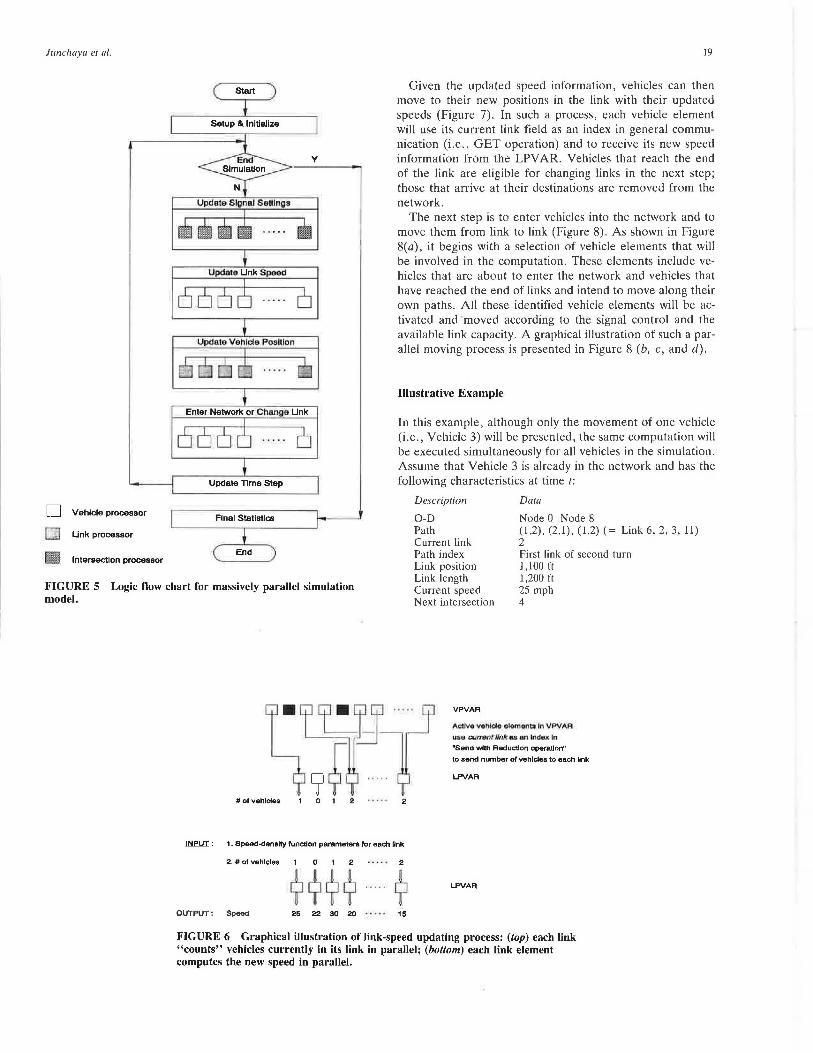
Figure 5 illustrates the real-time traffic simulation logic. Notice that it can be used not only on a Connection Machine, but also on other SIMD machines with minor modifications. Basically, compared with the need of using three nested loops in sequential computers, the proposed method contains only one time loop and three stages of execution. In the first stage, parallel variables for vehicles, links, and intersections are initialized from external files. These external files include (a) traffic demands generated from an 0-D matrix of individual vehicles with predetermined paths, and (b) network information of nodes, links, and signal control. The second stage involves the main simulation routine (Figures 6-8), which consists of four steps: updating signals, counting vehicles and updating link speeds, moving vehicles, and updating vehicles. A summary of simulation statistics is generated in the last stage.
The first step in the second stage is to update signal settings at all incoming links at all intersections in parallel. As shown in Figure 4 (middle), each link element contains signal information of start green and red time. At each step, start-red is checked against the system clock. If the start-red is less than the system clock, both start-green and start-red are incremented by cycle length from the IPV AR using the destination node as the index in the parallel left index operation.
The second step of the main simulation loop is to update the new prevailing speed for each link element in the LPV AR. Figure 6 shows how to compute each link element's volume and new prevailing speed at each time increment simultaneously. In Figure 6 (top), each vehicle element already in the network sends a signal to its current link element. Each link element then uses such information along with the speeddensity function to compute the new prevailing speed as shown in Figure 6 (bottom).
Junchaya et al.
D Vehicle processor
Q Link processor
. , Intersection processor
Start
Setup & Initialize
Update Time Step
Final Statistics
End
19
Given the updated speed information, vehicles can then move to their new positions in the link with their updated speeds (Figure 7). In such a process, each vehicle element will use its current link field as an index in general communication (i.e., GET operation) and to receive its new speed information from the LPVAR. Vehicles that reach the end of the link are eligible for changing links in the next step; those that arrive at their destinations are removed from the network.
The next step is to enter vehicles into the network and to move them from link to link (Figure 8). As shown in Figure 8(a), it begins with a selection of vehicle elements that will be involved in the computation. These elements include vehicles that are about to enter the network and vehicles that have reached the end of links and intend to move along their own paths. All these identified vehicle elements will be activated and ·moved according to the signal control and the available link capacity. A graphical illustration of such a parallel moving process is presented in Figure 8 (b, c, and d).
Illustrative Example
In this example, although only the movement of one vehicle (i.e., Vehicle 3) will be presented, the same computation will be executed simultaneously for all vehicles in the simulation. Assume that Vehicle 3 is already in the network and has the following characteristics at time t:
Description
0-D Path Current link Path index
Data
Node 0-Node 8 (1,2), (2,1), (1,2) ( = Link 6, 2, 3, 11) 2 First link of second turn 1, 100 ft
FIGURE S Logic flow chart for massively parallel simulation model.
Link position Link length Current speed Next intersection
1,200 ft 25 mph 4
#of vehicles 0 2 2
Ll'IEUI : 1. Speed-density !unction parameter& !or each link
2. # o1 vehicles 0 2 . . . . . 2
QUIJ>UI: Speed 25 22 30 20 15
VPVAA
Actlvo lfOhlclo olomonto In VPVAA
"50 currwnt. Onk u an •nC1&.11C In "Send wtth Reduction operallon"
to send number of vehlcles to each link
L.PVAA
L.PVAA
FIGURE 6 Graphical illustration of link-speed updating process: (top) each link "counts" vehicles currently in its link in parallel; (bottom) each link element computes the new speed in parallel.

20
Speed 25 22 30 20
lJllf'1lI : 1. Current poaldon, time Increment,
2. Speed 25 20 16 20 30
~-~9·?9 OUiel..IT: New poahlon In llnk
15
15
~
TRANSPORTATION RESEARCH RECORD 1358
VPVAA
Active vehicle elements In VPVAR u.so OUfTOIJf /Ink u fnd.ex In "Get operation" to receive new speed Information from LPV AR
LPVAA
VPVAA
FIGURE 7 Graphical illustration of updating process for each vehicle element's position and speed: (top) active vehicle elements inquire new speed information in parallel; (bottom) active vehicle elements update link position.
The parallel simulation process from time t to t + M is illustrated as follows:
For simulation time step t
Step
Update signal settings
Enter network or change links
Update link speed
Update vehicle position
Update time step
Action
Signal setting information for each movement in all elements of IPV AR is updated.
The computation in this step affects those vehicles that are entering the network or changing links. Vehicle 3 is already in the network, so it will not be involved in the computation and will remain idle until the next step.
First, all vehicles that are in the network send signals to the current link using link-ID as an index in parallel left indexing. In this case, Vehicle 3 sends a signal to Link 2 along with other vehicles that are in Link 2. Link 2 then uses this information to compute the new prevailing speed.
Vehicle 3 receives the new average speed information from Link 2 and updates its new position. Suppose Vehicle 3 travels an additional 100 ft to reach the end of Link 2 in this time step, which .makes it eligible to change to a new link in the next time step, t + ti.1.
Simulation time is increased by ti.t.
For simulation time step t + t::..t
Step Action
Update signal settings
Enter network or change link
Signal setting information for each movement in all elements of IPV AR is updated.
Vehicle 3 is now eligible to change to its downstream link. First it uses general communication to get signal information from LPV AR using current Link 2 as an index in a parallel left indexing operation. It also uses downstream Link 3 as an index in a get operation to receive link capacity information from LPV AR. If traffic signal is green and there is no spillback, Vehicle 3 is allowed to move to Link 3.
The information currently stored in Vehicle 3 data elements will be
Description
0-D Path Current link Path index Link position Link length Current speed Next intersection
Data
Node 0-Node 8 (1,2), (2,1), (1,2) ( = Link 6, 2, 3, 11) 3 Second link of second turn 0 1,500 ft 20 mph 5
These models have been implemented on the Connection Machine in C* (18), an American National Standards Institute C-standard with parallel extension. Several si1nulation experiments have been carried out to test various factors affecting the running time on the Connection Machine. The results for these simulation experiments will be fully reported later (21). However, from our preliminary simulation experiments, we have been able to simulate 32,000 vehicles for 30 min at 2-sec increments within 2 min using the Connection Machine with 16,384 processors.
ONGOING RESEARCH ACTIVITIES
This paper presents our preliminary research in evaluating the applicability of massively parallel SIMD machines to simulate networkwide traffic in real time. The proposed model is part of the ongoing research to develop a real-time traffic simulation model for IVHS application. These research activities and related studies can be categorized into three areas: enhancement of SIMD models, development of traffic simulation methodology for MIMD machines, and integration with a real-time dynamic assignment model.
Main enhancements to the proposed SIMD model are to incorporate microscopic mechanisms such as car-following and lane-changing logic. Such logic can be added to the model using the same structure for parallel variables with some modifications. Further extensions of the model include the capability to model traffic incidents, lane closures, actuated signals, real-time surveillance systems, and ramp metering. The
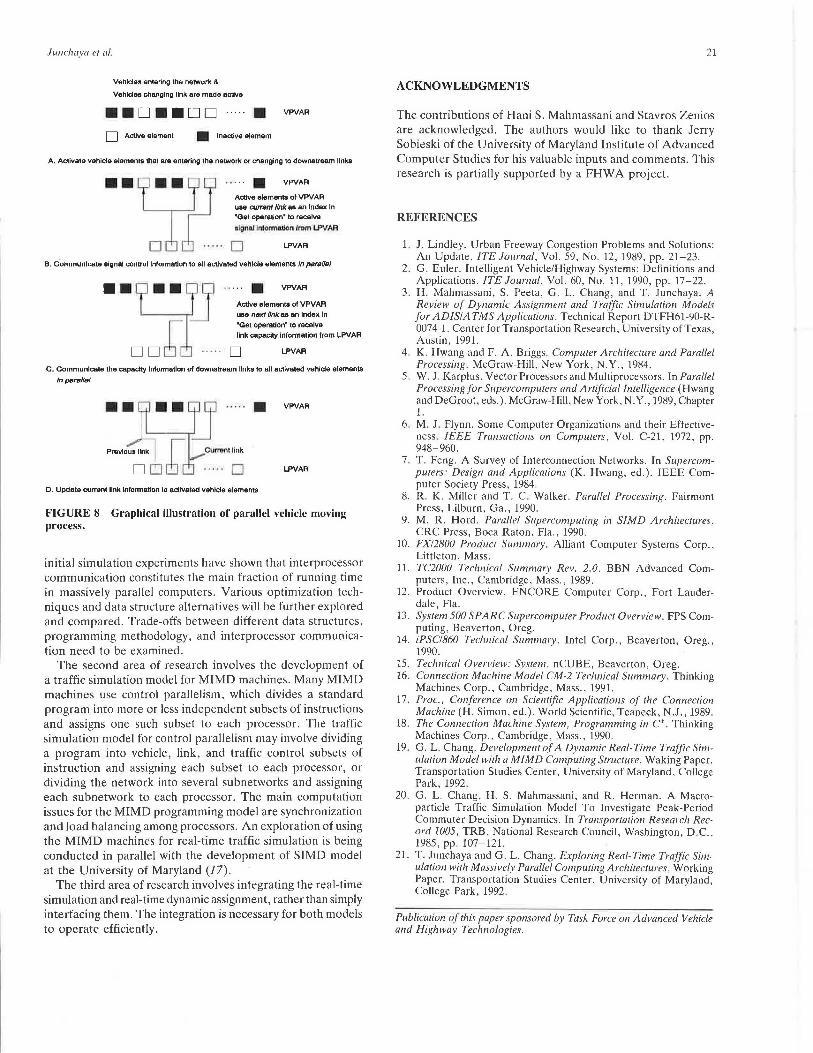
Junc/111ya el al.
Vehldes entering the network &
Vehlctes changing llnk are made active
••o••oo ····· • D Active element • Inactive element
VPVAR
A. Activate vehicle elemanla that are entering the network or changing to downstream llnka
VPVAR
Active elements of VPVAR ··:n··r .... ······ use current link aa an Index In "Get operation• to receive
olgnol lnfonn&tlon ''°'" LPVAR
0 LPVAR
B. c"ommunlcate signal control lnrormaUon to all activated vehicle elements In para/Isl
.. L .. IJ i~E:~ I link capacity inronnalion from LPVAR
D D 6 [ . . . . . D LPVAR
C. Communicate the capacity Information of downstream llnks to ell activated vehlde elements
lnparrtlfsl
~~9~~-···. ~~rf .... D
D. Update current llnk Information lo acUvated vehlcie elements
VPVAR
LPVAR
FIGURE 8 Graphical illustration of parallel vehicle moving process.
initial simulation experiments have shown that interprocessor communication constitutes the main fraction of running time in massively parallel computers. Various optimization techniques and data structure alternatives will be further explored and compared. Trade-offs between different data structures, programming methodology, and interprocessor communication need to be examined.
The second area of research involves the development of a traffic simulation model for MIMD machines. Many MIMD machines use control parallelism, which divides a standard program into more or less independent subsets of instructions and assigns one such subset to each processor. The traffic simulation model for control parallelism may involve dividing a program into vehicle, link, and traffic control subsets of instruction and assigning each subset to each processor, or dividing the network into several subnetworks and assigning each subnetwork to each processor. The main computation issues for the MIMD programming model are synchronization and load balancing among processors. An exploration of using the MIMD machines for real-time traffic simulation is being conducted in parallel with the development of SIMD model at the University of Maryland (17).
The third area of research involves integrating the real-time simulation and real-time dynamic assignment, rather than simply interfacing them. The integration is necessary for both models to operate efficiently.
21
ACKNOWLEDGMENTS
The contributions of Hani S. Mahmassani and Stavros Zenios are acknowledged. The authors would like to thank Jerry Sobieski of the University of Maryland Institute of Advanced Computer Studies for his valuable inputs and comments. This research is partially supported by a FHW A project.
REFERENCES
1. J. Lindley. Urban Freeway Congestion Problems and Solutions: An Update. !TE Journal, Vol. 59, No. 12, 1989, pp. 21-23.
2. G. Euler. Intelligent Vehicle/Highway Systems: Definitions and Applications. !TE Journal, Vol. 60, No. 11, 1990, pp. 17-22 .
3. H. Mahmassani, S. Peeta, G. L. Chang, and T. Junchaya. A Review of Dynamic Assignment and Traffic Simulation Models for ADISIATMS Applications. Technical Report DTFH61-90-R-0074-1. Center for Transportation Research, University of Texas, Austin, 1991.
4. K. Hwang and F. A. Briggs. Computer Architecture and Parallel Processing. McGraw-Hill, New York, N.Y., 1984.
5. W. J. Karplus. Vector Processors and Multiprocessors. In Parallel Processing for Supercomputers and Artificial Intelligence (Hwang and DeGroot, eds.). McGraw-Hill, New York, N.Y., 1989, Chapter 1.
6. M. J. Flynn. Some Computer Organizations and their Effectiveness . IEEE Transactions on Computers, Vol. C-21, 1972, pp. 948-960.
7. T. Feng. A Survey of Interconnection Networks. In Supercomputers: Design and Applications (K. Hwang, ed.). IEEE Computer Society Press, 1984.
8. R. K. Miller and T. C. Walker. Parallel Processing. Fairmont Press, Lilburn, Ga., 1990.
9. M. R. Hord. Parallel Supercomputing in SIMD Architectures. CRC Press, Boca Raton, Fla., 1990.
10. FX/2800 Produc/ Summary. Alliant Computer Systems Corp., Littleton, Mass.
11. TC2000 Technical Summary Rev. 2.0. BBN Advanced Computers, Inc., Cambridge, Mass., 1989.
12. Product Overview. ENCORE Computer Corp., Fort Lauderdale, Fla.
13. Sys/em 500 SPARC Supercomputer Produc/ Overview. FPS Computing, Beaverton, Oreg.
14. iPSC/860 Technical Summary. Intel Corp., Beaverton, Oreg., 1990.
15. Technical Overview: Sys/em. nCUBE, Beaverton, Oreg. 16. Connection Machine Model CM-2 Technical Summary. Thinking
Machines Corp., Cambridge, Mass., 1991. 17. Proc., Conference on Scienlific Applicalions of the Connection
Machine (H. Simon, ed.). World Scientific, Teaneck, N.J., 1989. 18. The Connection Machine Sys/em, Programming in C*. Thinking
Machines Corp., Cambridge, Mass., 1990. 19. G. L. Chang. Development of A Dynamic Real-Time Traffic Sim
ulation Model with a MIMD Computing Slructure. Waking Paper. Transportation Studies Center, University of Maryland, College Park, 1992 .
20. G. L. Chang, H. S. Mahmassani, and R. Herman. A Macroparticle Traffic Simulation Model To Investigate Peak-Period Commuter Decision Dynamics. In Transportation Research Rec· ord 1005, TRB, National Research Council, Washington, D.C., 1985, pp. 107-121.
21. T. Junchaya and G. L. Chang. Exploring Real-Time Traffic Simulation with Massively Parallel Computing Architeclures. Working Paper. Transportation Studies Center, University of Maryland, College Park, 1992.
Publicalion of this paper sponsored by Task Force on Advanced Vehicle and Highway Technologies.