advanced sensors and instrumentation · discussions between members of the technical staffs at...
TRANSCRIPT

PRESENTATION 3.2.3
N91-17041
ADVANCED SENSORS AND INSTRUMENTATION
521
https://ntrs.nasa.gov/search.jsp?R=19910007728 2020-05-23T04:28:18+00:00Z


SPACE TRANSPORTATION AVIONICS
TECHNOLOGY SYMPOSIUM
Williamsburg, VANovember 7-9, 1989
ADVANCED SENSORS AND INSTRUMENTATION
WHITE PAPER
Raymond S. Calloway
Flight Instrumentation BranchLangley Research Center
Hampton, VA 23665-5225
Joe E. Zimmerman
Marshall Space Flight Center
Kevin R. Douglas
Lockheed Engineering & Sciences Company
Rusty Morrison
Rocketdyne International
523
PRECEDING PAGE BLANK NOT FILMED


ADVANCED SENSORS AND INSTRUMENTATION
WHITE PAPER
Raymond S. CallowayFlight Instrumentation Branch
Langley Research Center
Hampton, VA 23665-5225
December 6, 1989
Background
NASA is currently investigating the readiness of Advanced Sensors and
Instrumentation to meet the requirements of our nation's new initiatives in
space. Pre-symposium, Space Transportation Avionic Technology (STATS),ad-hoc discussions were focused on identifying strategic sensor and
instrumentation technologies. The content of this paper resulted fromdiscussions between members of the technical staffs at Langley, Johnson,
Marshall, and Rockwell International. Summary suggestions per organization
are attached as appendixes to this white paper.
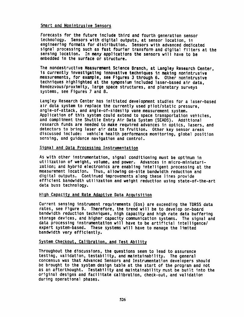
The STAT presentation was focused around the 8 quad charts, see Figures 1and 2.
Not knowing the specific technical objectives of individual missions, the
group identified and discussed the following strategic technologies:
e Smart and nonlntruslve sensors
e On-board signal and data processing
e High capacity and rate adaptive data acquisition systems
e On-board computing
e High capacity and rate on-board storage• Efficient on-board data distribution
e High capacity telemetrye Ground and flight test support instrumentation• Power distribution
e Workstations, vldeo/llghtlng
The goal of thls white paper Is to capture the substance of the
presentation and technology discusslons during the subpanel meeting.The requirements for higher fidelity data (accuracy, frequency, quantity,
spatial resolution) in hostile environments will continue to push the
technology developers and users to extend the performance of their products
and to develop new generations. In some technology areas, this process mayacquire a strong active leadership from NASA. Thus, there is a need for a
workshop just for Advanced Sensors and Instrumentation.
525P,,,._. .... .,.,L, _ _-._,-- CLA[;K NOT FiLM_
Smart and Nonlntrusive Sensors
Forecasts for the future Include thlrd and fourth generation sensortechnology. Sensors with digital outputs, at sensor location, Inengineering formats for distribution. Sensors with advanced dedicatedsignal processing such as fast fourier transform and dlgltal filters at thesensing location. In many applications the sensors w111 have to beembedded In the surface or structure.
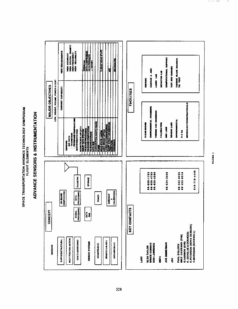
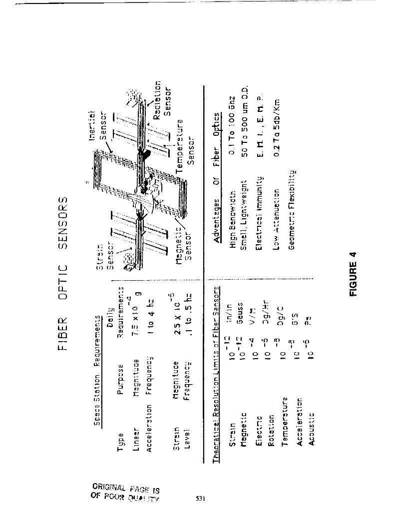
The nondestructive Measurement Science Branch, at Langley Research Center,Is currently Investigating Innovative techniques in maktng nontntruslvemeasurements, for example, see Figures 3 through 6. Other nontntruslvetechniques highlighted at the symposium lncluded laser-based air data,Rendezvous/proximity, large space structures, and planetary surveyssystems, see Figures 7 and 8.
Langley Research Center has initiated development studies for a laser-based
air data system to replace the currently used pllot/static pressure,
angle-of-attack, and angle-of-sldesllp vane measurement system.Appllcation of thls system could extend to space transportation vehlcles,
and compliment the Shuttle Entry Alr Data System (SEADS). Additional
research funds are needed to make required advances in optics, lasers, anddetectors to bring laser air data to fruition. Other key sensor areas
discussed include: vehicle health performance monitoring, global positionsensing, and guidance navigation and control.
Signal and Data Processinq Instrumentation
As with other instrumentation, slgnal conditioning must be optimum inutilization of weight, volume, and power. Advances in micro-mlnlaturl-
zation; and hybrid electronics are enabllng Intelligent processing at themeasurement location. Thus, allowing on-slte bandwidth reduction and
digital outputs. Continued improvements along these lines provide
efficient bandwidth utllizatlon and weight reduction using state-of-the-artdata buss technology.
High Capacit_ and Rate Adaptive Data Acquisition
Current sensing instrument requirements (Eos) are exceeding the TDRSS data
rates, see Figure 9. Therefore, the trend wlll be to develop on-board
bandwidth reduction techniques, high capacity and high rate data buffering
storage devices, and higher capacity communlcatlon systems. The signal anddata processing instrumentation wlll have to be artificial intelligence/
expert system-based. These systems will have to manage the limitedbandwidth very efflclently.
S3stem Checkoutl Callbratlon, and Test Ablllt_
Throughout the discussions, the questions seem to lead to assurancetesting, validation, testability, and maintainability. The generalconcensus was that Advanced Sensors and Instrumentation developers shouldbe brought to the system design table at the start of the program and notas an afterthought. Testability and maintainability must be bullt Into theoriginal designs and facilitate calibration, check-out, and validationduring operational phases.
526

Summary
There were many good questions asked and discussions focused around typical
engineering concerns:
• Increased rellablllty and accuracy for performance evaluation
e How to pre-fllght, checkout, callbrate, and post-fllght maintenance
e Reduce quantity to cables for data collection/sensor interrogation
e How to valldate expert systems?
• Intelllgent data reduction on-board
Most of the technlcal issues discussed are captured In the quad charts.
Major contributors' on-golng research areas are displayed In the
appendixes.
527
528

=:
,z z
Z-r'o __
)- U,Ire0 cna,. ILlolz C.)< Z
uao r,,< ,<Q.(n
A
l*i !-°.a
(n
c_
|o
0 0 0 0 000 0000000000000
!
! i°°I0 0 0 0 0 0 0 0 0 0 0
' li !__ .
:' "-"i_ !'_jl!_ |; ;,
!
Z
c.el"
m z
ee CjeL U_
_P0
< o_,. Zm <
529 ORIGINAL PAGE IS
OF POOR QUALITY

Zn
rr'0
ZLI,J
530
U)EKE_U)
L_JU3
(_3
ft..0
EKLJJrrl
EL
£-
, 0 k--
L. r" ' " "iapl _+., I,,,...
,-_,,, F_<JHI-:-.++I.,-,,i "' _ 4 ..... I OJ -
+
,-+; ....11111_i mo,: ,.+.-I' lllll--_ +J,
+., (=++ '+_+_._
.Q
I1
/
.IDu_o_
>
l-
o_
ffl
oE
om
I-
W
m
U.
532
(I; _Q)
:_ E -_=-- 0 IE_,, (I) ,.__:0") (I)--
lID
.1
533

m
534

0
C3_J
><ILJ
IJJL)
(/)
|L
(./)
C_(/)
L|I(/)
LIJ(./')
L_bI--
J_c/)
I
.+-+
_.J
(./3
M
t--
--J I--
LLJ :_ "J-"I-"- LIJ ,--,
--+J llJ Q_J c+) £_ill < (_.
(.,') _ L£Jc.) (-'J ,_,,.-
(2:) r._l "-'Jt.t_ l-- LLJ ¢/)
C.-,--_ _ _-" ._.--|lJ I-- L.LJ r-,,-
ILl :1_ C_ "7
ILl - l
I.J,J (.,1.4_e+J I-J.J C_)_. L) LAJ
(Z) ._.l C_ I--
:31"L'_I-- I.LI4t.+J _ (,/) IIJIll tll (.-J
(]+) P"'+ _ l+IJ
LLI <._IIJ --JI_ _ tt-_1_ LIJ C_ •
I I:,_1 t£l
l./') C'_ >.< l_-
(_.J LIJ C_ILl-f-- ,+.,_<
I_ "_ I
I:./')
LIJ ",(/) .--..
,,'sLtJ (./+'J
I t..)
_---"_ LLI I--
.... I C._ _.._
Z,O 1_- I--
_1 ILl'--"I+JJ _>" (,0_X..--, (,0Z:: I-- ,,:I::
.-.i IJJ
_1._ LL i+-"Ill LIJ "-_
(./) i_ l::x_
L)LtJ
i,--+ +
|IJ I+",.
(.1/) (]) i:_c.,,+,. ,m_ (_LLJ -J m
(.]') If+| Il-
l- "'- t.J Ill
_, _ 11- _ _
._.< c/) _+"_ I./)
J[_- 1:_ t.J t,, r)
<./) _ I:_ I_. l l.l
lll I--
_- ILJ L.O Z 1:1-
l_ --J *-"4 _+" L)
llJI I
C,,+)
LIJ (L/'J(./)_1: Ill
1£I '-"+
I-- --Jinl...
I-- -Jr-"C,,') ,_C
I
,.--, II l.-I
.--J
Ill III
c,.
"_ IJ.
c./)_ L 1 j
LitJ ,----,,
(_J I--
(./) -+(: I[_+
•--. tll Z LIII-- (.,,_ I:_) (,.,Q
C) ---II-- "" IiJ
(]) LII l-- m
l_i C::) ._: lit_li.-,
LIJ _ (./)_ Ill
-'++ I.tl
L.) *--* _ _.J:_ _ ._J
+J
1::3.,.1:(::)Ill _ It_ __j
LJ _ (,0
1 _ llJ ,--, _.C/) _.J
,L.._ ._J C_ ,,_
•-J I 1
--J0
(:3
I'-(.+.)""-,
_.lJI-- (,0(I) <_•4-. _ J
( ) illIll I--
I--
_ I
•j,._ ,--.r+ ,...+
'"-+ _" ilJ
•m( ,_:(,t,) -_.
"_ I-- L._(,'_ I_l _ llJ ,---,
llJ ILJ _r_ C.,e) _ _"
<-1_ 4_ I-- ",
tll (./') Z LLI_>- l.IJ '-'+ LIJ l--
t/) Ill _ I'-'->- I I-- :_: (+.+)
.._ +--* _::_. l.J.J _Jt-- .--I _r- 4:_ L,LI+lJ (_ C_I ,.--, I.lJZ (+,') CJ ._ ,Y
-- J
I:X+ I I I
00
iiin-'
mn
I,IL
C3 O
535ORIGINAL PAGE IS
OF POOR QUALITY

i
II,I
0tL
536

APPENDIX 1
Kevln R. Douglas
Lockheed
Engineering & Sciences Company
537"

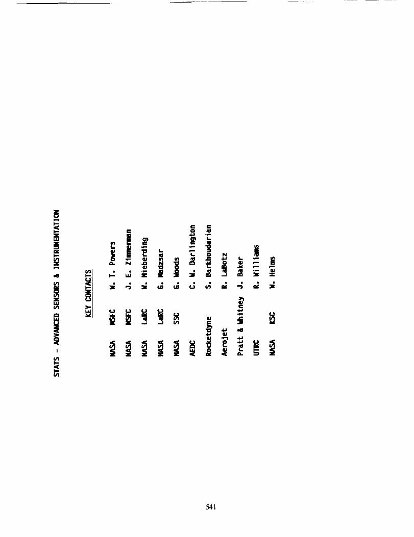
ADVANCED SENSORS & INSTRUMENTATION
ADVANCED SENSORS & INSTRUMENTATION
Micro-gravity TransducersThin Film Transducers
Fiber Optic Transducers and Transmission Lines
Smart Skins: Fiber Optic Transducers and Transmission lines embedded inadvanced composites;
Micro-machined Transducers: Employing classical semiconductor processing
techniques to build mechanical structures and transducers;
Smart Transducers: Integration of a transducer, signal conditioning,
programmable embedded micro-controllers;Advanced Instrumentation: Integration of Smart Transducers into a
distributed bus or fault tolerant Local Area Network (LAN);
Hybrid Electronics and Surface Mount Technology
MAJOR OBJECTIVES
Low Cost
Low WeightSmall Volume
Low Power
Higher Accuracy: Local Signal Conditioning and Data Conversion
Self Calibration, Zero Offset, and Zero DriftFunction in Remote Locations and Severe Environments
Adaptable to future data processing requirements (Digital Input/Output)Provides a technology base for next generation instrumentation systems
KEY CONTACTS
R. Calloway/LaRCM. Gaudiano/JSC EHB
G. Harmon/JSC EH6
K. Douglas/LockheedK. Peterson/Nova Sensors
MAJOR MILESTONES
Review Technology (1990)Establish Interface and Architectures
Define Hierarchy of Functions (1991)
Analysis and Demo in the Laboratory (1992)
TECHNOLOGY ISSUES
Integration of diverse transducers and different signal types into a SmartTransducer Module
Radio Frequency Transmission, Fiber Optic Links, Infrared Transmission
Digital Input/Output Interfaces
Continued progress in Smart Skins (demonstration phase only)Continued advances in micro-machinlng of transducers
Standards yet to evolve for Surface Mount Technology
538
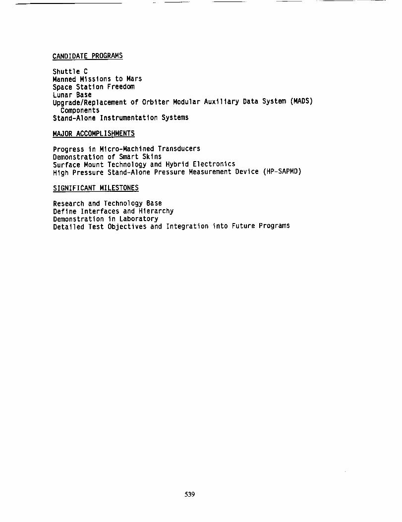
CANDIDATE PROGRAMS
Shuttle C
Manned Missions to Mars
Space Station FreedomLunar Base
Upgrade/Replacement of Orbiter Modular Auxiliary Data System (MADS)
ComponentsStand-Alone Instrumentation Systems
MAJOR ACCOMPLISHMENTS
Progress in Micro-Machined TransducersDemonstration of Smart Skins
Surface Mount Technology and Hybrid Electronics
High Pressure Stand-Alone Pressure Measurement Device (HP-SAPMD)
SIGNIFICANT MILESTONES
Research and Technology Base
Define Interfaces and Hierarchy
Demonstration in Laboratory
Detailed Test Objectives and Integration into Future Programs
539

APPENDIX 2
Joe Zlmermn
Narshall Space F11ght Center
540
541

0 O
!
i ! "j,.-
,_ r" I *" _'
542

General
Research and development programs are being conducted for improvement of
sensors used on present Space Transportation Systems, providing sensors for
current engine requirements where no practical measurement techniques are
commercially available, and to assure availability of measurementtechnology to meet future Space Transportation Avionics System
requirements. Benefiting programs will Include the Space Shuttle Elements(SSME and SRB), Advanced Launch Vehicle, Orbital Transfer Vehicles, and
long-duration space flights or exploration program.
Earth-To-Orbit Propulsion Proqram
One group of research projects being conducted is under the Civil Space
Transportation Initiative (CSTI) and specifically the Earth-To-Orbit (ETO)Chemical Propulsion program. The ETO program is a joint MSFC and LaRC
effort with research projects being performed in-house and through outside
contracts with other Government agencies, universities, and privateindustry. The emphasis of the ETO program is the continuing enhancement of
knowledge, understanding, and design methodology applicable to the
development of advanced Oxygen/Hydrogen and Oxygen/Hydrocarbon propulsionsystems. Significant research activities in the ETO program are summarized
in the following paragraphs.
An Optical Plume Anomaly Detector (OPAD) is being developed to view andanalyze the SSME exhaust plume with the intent of obtaining information
that would provide early indications of engine component degradation and/or
precursors to a catastrophic engine failure. OPAD components include high
resolution spectrometers and optical multi-channel analyzers. Testing of
the OPAD during SSME engine firings at the Stennis Space Center (SSC) and
at MSFC has been extremely successful and plans are being made to installground-based OPAD systems at each test and launch facility. The potential
of a flyable OPAD is also being investigated to provide input to a health
monitoring system. An in-flight system could also provide information onnormal engine component wear and possibly reduce the amount of disassembly
and physical inspections of the engines after each flight.
Advanced cryogenic flowmeters are being developed for use on SSME class
engines. Vortex shedding flowmeters have been designed and tested withpromising results in some of the SSME ducts. Nonlntrusive ultrasonic
flowmeters are also scheduled for feasibility testing in the FY 90-91 timeframe.
Other nonintrusive sensors under development for use on the SSME includes
electromagnetic speed sensors for monitoring turbo pump speed, infrared hot
gas temperature sensor for monitoring turbine exhaust temperatures, and a
Raman backscatter thermometer for determination of temperature distributionwithin the pre-burners of the SSME. These sensors have successfully
completed laboratory evaluation testing and are in the design phase fortesting in an engine environment.
Solid-state and fiber optic based pressure sensors are being investigated
for potential use on the SSME. These devices are being designed for direct
mounting on cryogenic ducts to replace existing sensors which have to be
off-mounted due to thermal sensitivity of the conditioning electronics.
543

Gaseous leak detection techniques are being lnvestlgated and developed forremote sensing of hydrogen leaks from space vehlcle plumbing systems.Current senslng techniques are limited to point sensors which requiresprior knowledge of the location of the leak or an extremely large number ofsensors located around the vehicle to effectively quantify the leakage.
A nozzle exit plane measurement system is being developed for
identification of species and flow veloclty determination at the exit of
the SSME nozzle. The system uses laser-induced flourescence to tag
molecules in the flow stream for processing to determine specieconcentrations and velocitles. The system is being developed for
combustion code validations and engine performance analysls.
Thin film sensors are being developed for deposition on turbine blades and
other engine components which require minimally intrusive diagnostics.Film deposition processes have been developed for measurement of
temperature and heat flux on SSME turbine blades. Initial testing of
instrumented blades has been accomplished on the Turbine Blade Tester at
MSFC with promising results.
Solid Propulsion Integrity Program
Another group of research projects under the CSTI program are included in
the Solid Propulsion Integrity Program (SPIP). The instrumentationdevelopment task is a sub-element of a Nozzles Technology effort monitored
by MSFC. Instrumentation research includes investigations and development
of new or advanced measurement techniques for use on or in compositematerials of solid rocket motor nozzles. Emphasis is on high temperature,
high response sensors for the measurement of temperature, strain, pressure,
and stress in the composite materials. Tasks include investigation ofattachment techniques and operational capabilities to the 1100"C
temperature range for strain, stress, and pressure sensors. Fiber optic
techniques are being studied for these applications. Attachment techniquesinclude both surface mounted and embedded sensors. Another type sensor
under investigation is a recession gage to measure erosion of the throat
material during a motor firing. Sensors developed under the SPIP programwill be tested and evaluated in the solid rocket motor test beds at MSFC.
Space Station Freedom Related
Three significant development projects are being conducted with
appllcatlons on Iong-duratlon manned space ventures. All are involved withmonitoring the atmosphere within a habitable enclosure.
An advanced Tandem Mass Spectrometer is being developed for tracecontaminant monitoring. This spectrometer wlll reduce the time required to
obtain a readout of the contaminant present from 30 minutes to 5 minutes,
giving near real-time warning of hazardous conditions. The developmenteffort is in Phase II of a Small Business Innovative Research (SBIR)
program.
Another Phase II SBIR is being supported for the development of a Trace
Atmospheric Carbon Monoxlde Sensor. The obJectlve is to develop a compact,sensitive CO sensor which is species selective and has low power
consumption. The sensor uses a nondlsperslve infrared technique.
544

A Hazardous Materlals Honltor (HHM) system Is also under Investlgatlon for
monltorlng 5 groups of contamlnants whlch mlght be found In a space statlonmodule. The groups are: meta111c vapors; meta111c aerosols; organlc
solvent vapors; gases, fuels, and combustlon products; and etchants. TheHMM w111 be used to sense Inadvertent leaks of hazardous substances from
experlments on-board Space Statlon Freedom and provide early warning for
the crew to take approprlate remedlal or evaslve actlon. There Is
presently no other such monitoring system planned for the space station.
545

APPENDIX 3
Rusty Norrlson
Rocketdyne International
546

Advanced Sensor and Instrumentation development work at Rocketdyne and in
the rocket engine world in general has been driven primarily by safety andmaintenance considerations rather than control needs. The desire is to
detect degradation in the engine in time to alter operation (shutdown orthrottle back) to protect the crew and mission and/or diagnose condition,
predict 11fe, schedule maintenance, and support automation of ground
operations. To these ends, studies dating back to 1980 have analyzed
actual engine field operational recorded to determine historic degradationmodes (example-89CA-079-41) and estimated current design and development
information on current designs. These modes and the component mostaffected by them are summarized in table 89CA-079-42. Measurements have
been identified at each stage of the degradation process and surveys ofsensor technologies have been conducted to identify concepts with maximum
payoff potential. Table 490-660A identifies the technologies currentlyunder development for applicatlon to rocket engines.
Multi-disciplinary issues must be addressed in any sensor system concept.
An integrated approach to system definition involves the engine system andcomponent designers who define the measurants of interest and required data
rates; the engine control system designer addressing functional
distribution of processing, bus data rates, etc.; and the sensor designteam itself which includes the sensor designer(s), the designer(s) of thepart to which the sensor is mounted, associated stress, structural
dynamics, thermal analysis, and the process physicist who relates the
measurement of interest to what is recorded by the sensor. In the contextof this integrated approach, smart sensors, in which the transducer itself
outputs a digital data stream, optical sensors capable of easily
integrating directly with fiberoptic data buses and tolerating extreme
environments, and non-intrusive sensor technologies which don't penetratepressure containers or interfere with the process being measured arecurrent thrusts.
547

ADVANCED INSTRUMENTATION TECHNOLOGIES AND PROGRAMS
Summaries are given below of representative advanced instrumentationtechnologies under development for rocket engine appllcatlons. Research
referred to includes that being performed by Rocketdyne Instrumentation
personnel under IR&D, SSME Technology Test Bed, and Orbltal TransferVehicle Englne tasks.
The general goal of these efforts is to improve mission safety, confldence,readlness, and llfe cycle costs. Corollary goals are to accelerate
turnaround times and to help reduce the "standing army" associated with
between flight inspection and qualification of reusable englnes. In
addition, nonlntrusive and/or nonprotruslve technologies are being
developed to reduce the hazard associated with conventional measurementtechnologies or to provide valuable diagnostic data currently unobtainable
because of hostlle englne envlronments.
Several technologies developed for space transportation may be adaptable tomanufacturing applications (e.g. leak tests and weld inspections). One of
the underaddressed applications of advanced instrumentation for space
transportation in general is its role in manufacturing processes. Focusingon monitoring and inspection capabilities over the entire life cycle of the
system, from the start of manufacturing and throughout the system operatlnglife, would provide the greatest gains in reduced llfe cycle costs and
improved mission readiness.
No fundamental cultural changes at NASA seem necessary to support
development of these technologies: numerous programs are initiated to
support this development. Nevertheless, improved communication andcoordinatlon would be helpful between the different NASA divisions, between
NASA and other Government agencies, and between NASA and companies
developing or potentially using these technologies. This will provide a
better brldge between the development of these technologies and theirapplicatlon in transportation systems. In this regard, accelerated funding
is called for to allow timely implementation of the most promising of these
technologies.
Bearinq Deflectometr3
Description: A probe containing an optical fiber bundle is mounted in the
engine with its tip in close proximity to the outside of a bearing race.Based on the Intenslty of light reflected from the race and back into the
probe, minute deflections of the race surface are monitored at high
frequency. This has proven in turbopump testbed applications to be a very
sensitive indicator of bearing vibrations which can be correlated to
bearing condition in real-time.
Programs: SSME Technology Testbed
Key Researchers: J. Collins and C. Martinez
Addressed Transportation Needs: Improved flight safety, accelerated
turn-around times, disassembly for cause rather than schedule, reduced life
cycle costs, and improved mission confidence.
548
Time for Implementation Readiness: ca 1991
Relationship between technology development and transportation system
development for this topic: Provisions for incorporation of the
fiber optic probe(s) should be included in the engine design process. An
historical database should be developed to quantitatively correlate bearingdeflectometer signatures to bearing conditions in operating engines.
Isotope Wear Analysis
Description: Prior to engine assembly, a selected component is endowedwith a low level of radioactivity on a portion of its surface. After
assembly, the level of radioactivity is monitored between firings with a
detector/analyzer operating externally to the engine. The loss of
radioactivity is correlated to mass loss at the component surface with aresolution on the order of micrograms. The determined mass loss can be
used to calculate remaining llfe of the component accurately without
requiring engine disassembly.
Key Researchers: J. Collins, M. Randa11, and S. Barkhoudarian
Addressed Transportation Needs: Accelerated turn-around times, disassembly
for cause rather than schedule, reduced life cycle costs, and improvedmission confidence.
Time for Implementation Readiness: ca 1990
Relationship between technology development and transportation system
development for this topic: Pre-irradiation of components requiring wear
monitoring should be included as part of engine fabrication procedures.This will allow application of this nonintrusive technology.
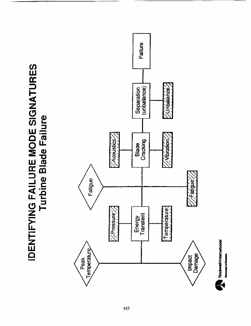
Fiber Optic Turbine Blade Pyrometry
Description: A fiber optic probe is used to collect infrared thermal
radiation from turbine blades as they rotate past the probe. This
radiation is analyzed to determine temperature profiles of each blade in
real-time. This information is used to identify small blade cracks which
create hot spots, and other indicators of incipient blade failure.
Programs: SSME Technology Testbed, Reusable Rocket Engine Turbopump Health
Monitoring Program
Key Researchers: J. Collins and M. Randall
Addressed Transportation Needs: Improved flight safety, accelerated
turn-around times, disassembly for cause rather than schedule, reduced lifecycle costs, and improved mission confidence.
Time for Implementation Readiness: ca 1992
Relationship between technology development and transportation system
development for this topic: Provisions for incorporation of the
fiber optic probe should be included in the engine design process. Ahistorical database should be developed to quantitatively correlate
549

pyrometer slgnatures to blade conditions in operating rocket engines.
Between-Flight Optical Leak Detection
Description: During between-flight inspection, an engine or other
component is pressurized with an inert infrared-absorbing gas. The engineis illuminated wlth infrared light and monitored with an infrared camera.
An infrared image of the engine, with leaking gas appearing as dark clouds
in the vlclnity of the leak, is provided by the infrared camera. Leaks
from large sections of the engine are thereby _onitored simultaneously and
rapidly with high sensitivity (down to 5 x 10-_ sclm). This technology issubstantlally more amendable to automation than currently used techniques
for leak location and quantlflcation. This would make possible system leak
inspection times on the order of a few mlnutes. Current programs: SSME
Technology Testbed, Rocketdyne Advanced Instrumentation IR&D.
Key Researchers: R. Delcher, M. Randall, and J. Maram
Addressed Transportation Needs: Improved flight safety, accelerated
turn-around times, disassembly for cause rather than schedule, reduced llfe
cycle costs, and improved mission confidence.
Time for Implementation Readiness: ca 1990
Relationship between technology development and transportation systemdevelopment for this topic: Qualification of an appropriate pressurant gas
for optical leak checks should be part of the transportation system
development.
In-flight (Propellant) Optical Leak Detection
Description: Optical methods are being developed for real-time detection,location, and quantification of propellant leaks in flight or in space.
Among the methods being considered are light absorption/imaging techniquesin the infrared or ultraviolet similar to the method described for
between-flight leak detection. Other optical techniques, including Raman
scattering, also show significant promise and are being investigated.
Key Researchers: R. Delcher, D. Gobeli, and J. Maram
Addressed Transportatlon Needs: Improved flight safety, accelerated
turn-around times, disassembly for cause rather than schedule, reduced life
cycle costs, and improved mission confidence.
Time for Implementation Readiness: ca 1993
Relationship between technology development and transportation system
development for this topic: Provisions for optical accessibility to
external engine components would improve the effectiveness of this
technology.
Remote Plume Spectrometry
Description: Light from rocket engine plumes is monitored with remote,
ground-based optics. The light is analyzed spectrometrically to detect and
550

measure the quantity of molecular and atomic constituents in the plume.
Such measurements have been made at Rocketdyne and at SSC in over a hundred
engine test flrlngs. These measurements are valuable tools incharacterizing and distinguishing nominal and anomalous engine conditions.
Furthermore, measured levels of several key plume constituents can serve as
effective indicators of anomalous component wear and provide an early
indicator of potential engine failure. For example, calcium-based
constituents are characteristic of plume spectra from rocket engines suchas the SSME, corresponding to nominal bearing cage wear. Plume spectra
recorded in engine tests resulting in bearing cage failure have indicated
substantial rise in these calcium-based constituents up to hundreds of
seconds before redline detection and shutdown. Early detection ofanomalous wear in nlckel-alloy and copper components has also been
accomplished by this means. Such diagnostics strongly suggest themselves
as tools for early detection and minimization of failure damage.
Key Researchers: L. Wyett, J. Relnert, and D. Gobe]l
Addressed Transportation Needs: Engine characterization, improved flightsafety, accelerated turn-around times, disassembly for cause rather than
schedule, reduced llfe cycle costs, and improved mission confidence.
Facilities in Use: Rocketdyne Advanced Instrumentation Laboratory, SantaSusana Field Laboratories, and Stennls Space Center
Time for Implementation Readiness: ca 1991
Relationship between technology development and transportation system
development for this topic: Provisions for optical accessibility to
external engine components would improve the effectiveness of thistechnology.
Ultrasonl c F1owmetry
Description: An ultrasonic flowmeter is used as a nonintrusive means to
measure propellant flow. A pair of ultrasonic transducers are mounted on a
propellant duct. Ultrasonic slgnals are transmitted and received between
the two transducers. The propellant flow velocity is determined by the
frequency shift in the ultrasonic signals, in a calculation independent ofpropellant density and temperature. This flowmeter is designed to replace
intrusive turbine flow_neters conventlonally used in rocket engines. In the
SSME Technology Testbed program, the ultrasonic flowmeter is beingevaluated to replace the oxidizer flowmeter which was deemed unacceptablefor the SSME and removed because of its intrusiveness.
Key Researchers: B. Szemenyei and S. Barkhoudarian
Addressed Transportation Needs: Engine characterization and improved
fllght safety.
Time for Implementation Readiness: ca 1991
Relatlonshlp between technology development and transportation system
development for this topic: Provisions for mounting the ultrasonic
transducers should be included in the selected duct design.
551

Nonlntruslve Speed Senslnq
Description: An externally mounted, nonlntruslve sensor Is used to measureturbopump shaft speed. Measurements are made by detection of fluctuationsin magnetic fteld at the sensor caused by the periodic passage of permanentmagnets embedded in the turbo pump speed nut. Thts technology has beendeveloped to replace the intrusive magnetic speed sensor formerly used onthe SSME oxidizer turbo pump.
Programs: None currently funded (formerly SSME Technology Testbed)
Key Researchers: L. Wyett, J. Relnert, and S. Barkhoudarlan
Addressed Transportation Needs: Improved f11ght safety and improvedmission confidence.
Time for Implementation Readiness: ca 1991
Relationship between technology development and transportation systemdevelopment for this topic: In vehicles where this technology is to beused, provisions for incorporation of the magnets tnto the rotatingassembly should be included in the engine design process.
552
mom
m_u
I
A
0 o
553

554

'" ' ¥099'06P _
555
