advanced physics course chapter 9: current electricity
TRANSCRIPT
A D V A N C E D P H Y S I C S C O U R S E
C H A P T E R 9 :
C U R R E N T E L E C T R I C I T Y
FOR HIGH SCHOOL PHYSICS CURRICULUM AND ALSO THE PREPARATION OF ACT, DSST, AND AP EXAMS
This is a complete video-based high school physics course that includes videos, labs, and hands-on learning.
You can use it as your core high school physics curriculum, or as a college-level test prep course. Either way,
you’ll find that this course will not only guide you through every step preparing for college and advanced
placement exams in the field of physics, but also give you in hands-on lab practice so you have a full and
complete education in physics. Includes text reading, exercises, lab worksheets, homework and answer keys.
BY AURORA LIPPER ∙ SUPERCHARGED SCIENCE 2017
© 2017 Supercharged Science Page 2
TABLE OF CONTENTS
Material List ............................................................................................................................................................................................................... 4
Introduction ............................................................................................................................................................................................................... 5
Electric fields are like Gravitational Fields ................................................................................................................................................... 6
Electric Potential ..................................................................................................................................................................................................... 7
Magnesium Battery................................................................................................................................................................................................. 8
Fruit Battery ............................................................................................................................................................................................................ 13
Solar Battery ............................................................................................................................................................................................................ 19
Salty Battery ............................................................................................................................................................................................................ 24
Taking A College Class in Electricity .............................................................................................................................................................. 30
Voltage ....................................................................................................................................................................................................................... 31
Balloon Rising in the Air ..................................................................................................................................................................................... 32
Point Charge ............................................................................................................................................................................................................ 33
Inside Gold ............................................................................................................................................................................................................... 34
Skiing Down a Mountain .................................................................................................................................................................................... 35
Review on Electric Potential Difference ...................................................................................................................................................... 36
Inside Uranium ....................................................................................................................................................................................................... 37
Electric Current ...................................................................................................................................................................................................... 38
Electric Circuits ...................................................................................................................................................................................................... 39
Detecting Current .................................................................................................................................................................................................. 45
Conductivity ............................................................................................................................................................................................................ 51
Requirements for a Circuit ................................................................................................................................................................................ 57
Water Analogy ........................................................................................................................................................................................................ 58
Franklin’s Mistake ................................................................................................................................................................................................. 59
Charge Carriers are Not Used Up .................................................................................................................................................................... 60
Switches .................................................................................................................................................................................................................... 61
Loads in a Circuit ................................................................................................................................................................................................... 69
Power ......................................................................................................................................................................................................................... 70
Making Sense of It All........................................................................................................................................................................................... 71
Electrical Resistance ............................................................................................................................................................................................ 72
Resistance over Distances ................................................................................................................................................................................. 73
Resistors .................................................................................................................................................................................................................... 74
Potentiometers ....................................................................................................................................................................................................... 76
Measuring Voltage and Current ...................................................................................................................................................................... 77
Ohm’s Law ................................................................................................................................................................................................................ 78
© 2017 Supercharged Science Page 3
Applying Ohm’s Law ............................................................................................................................................................................................ 79
Power and Ohm’s Law ......................................................................................................................................................................................... 80
Hair Dryer Problem .............................................................................................................................................................................................. 81
Toaster Problem .................................................................................................................................................................................................... 82
Bulb Wattage ........................................................................................................................................................................................................... 83
Circuit Connections .............................................................................................................................................................................................. 84
Series Circuits ......................................................................................................................................................................................................... 85
Parallel Circuits ...................................................................................................................................................................................................... 86
Calculating and Measuring Current ............................................................................................................................................................... 87
Ohm’s Law and Current ...................................................................................................................................................................................... 88
Ohm’s Law and Power ......................................................................................................................................................................................... 89
Applying Ohm’s Law ............................................................................................................................................................................................ 90
Series and Parallel Review ................................................................................................................................................................................ 91
Series and Parallel Circuits in Everyday Life ............................................................................................................................................. 92
Breadboards ............................................................................................................................................................................................................ 93
Series Switches ....................................................................................................................................................................................................... 94
Parallel Switches .................................................................................................................................................................................................... 95
Light Actuated Circuit .......................................................................................................................................................................................... 96
Light De-actuated Circuit ................................................................................................................................................................................... 97
How to Read Schematics .................................................................................................................................................................................... 98
Transistor Circuits ................................................................................................................................................................................................ 99
Audible Light Probe ........................................................................................................................................................................................... 100
Lie Detectors ........................................................................................................................................................................................................ 101
Homeowrk Problems with Solutions ......................................................................................................................................................... 102
© 2017 Supercharged Science Page 4
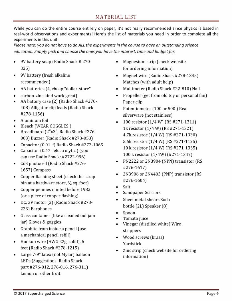
MATERIAL LIST
While you can do the entire course entirely on paper, it’s not really recommended since physics is based in real-world observations and experiments! Here’s the list of materials you need in order to complete all the experiments in this unit. Please note: you do not have to do ALL the experiments in the course to have an outstanding science
education. Simply pick and choose the ones you have the interest, time and budget for.
9V battery snap (Radio Shack # 270-
325)
9V battery (fresh alkaline
recommended)
AA batteries (4, cheap “dollar-store”
carbon-zinc kind work great) AA battery case (2) (Radio Shack #270-
408) Alligator clip leads (Radio Shack
#278-1156)
Aluminum foil Bleach (WEAR GOGGLES!) Breadboard (2″x3″, Radio Shack #276-
003) Buzzer (Radio Shack #273-053)
Capacitor (0.01 f) Radio Shack #272-1065 Capacitor (0.47 f electrolytic ) (you
can use Radio Shack: #2722-996)
CdS photocell (Radio Shack #276-
1657) Compass
Copper flashing sheet (check the scrap
bin at a hardware store, ½ sq. foot)
Copper pennies minted before 1982
(or a piece of copper flashing)
DC, 3V motor (2) (Radio Shack #273-
223) Earphones
Glass container (like a cleaned out jam
jar) Gloves & goggles
Graphite from inside a pencil (use
a mechanical pencil refill)
Hookup wire (AWG 22g, solid), 6
feet (Radio Shack #278-1215)
Large 7-9” latex (not Mylar) balloon
LEDs (Suggestions: Radio Shack
part #276-012, 276-016, 276-311)
Lemon or other fruit
Magnesium strip (check website
for ordering information)
Magnet wire (Radio Shack #278-1345)
Matches (with adult help)
Multimeter (Radio Shack #22-810) Nail
Propeller (get from old toy or personal fan)
Paper clip
Potentiometer (100 or 500 ) Real
silverware (not stainless)
100 resistor (1/4 W) (RS #271-1311)
1k resistor (1/4 W) (RS #271-1321)
4.7k resistor (1/4 W) (RS #271-1330)
5.6k resistor (1/4 W) (RS #271-1125)
10 k resistor (1/4 W) (RS #271-1335)
100 k resistor (1/4W) (#271-1347)
PN2222 or 2N3904 (NPN) transistor (RS
#276-1617)
2N3906 or 2N4403 (PNP) transistor (RS
#276-1604)
Salt Sandpaper Scissors
Sheet metal shears Soda
bottle (2L) Speaker (8)
Spoon Tomato juice Vinegar (distilled white) Wire
strippers
Wood screws (brass)
Yardstick
Zinc strip (check website for ordering
information)

© 2017 Supercharged Science Page 5
INTRODUCTION
Do you remember how a charged balloon can influence objects, like ping pong balls, water, and bits of
paper even when the balloon is not touching these things? The electric force from the charged balloon
acts over a distance, which is also known as an electric field force.
© 2017 Supercharged Science Page 6
ELECTRIC FIELDS ARE LIKE GRAVITATIONAL FIELDS
Electric fields are like gravitational fields in a couple of important ways. They both have forces that act at a distance. Remember with the gravitational field, in order to walk upstairs, you are doing work (exerting a force) against the pull of gravity. Your body naturally wants to be at the ground level, and it takes work to get it up a flight of stairs. You move from a lower potential energy to a higher potential energy as you walk up those stairs. When you walk up the stairs, you are adding gravitational potential energy to your body. And it doesn’t matter how wacky the staircase is… it can have curves, dips, switchbacks, and more… but it’s only the beginning and end points that we care about when calculating the gravitational potential energy. Electric fields work the same way, except with charges. In order to move a charge in an electric field against the way it naturally wants to go, you have to do work on it by applying an external force. This work done adds to the potential energy of the charge in the form of electrical potential energy. And it doesn’t matter what the path is that the charge takes between the two points… it’s only the beginning and ends points that matter. Both the electrostatic and gravitational forces are conservative forces. When you walk up a flight of stairs, the amount of gravitational potential energy stored in your body depends on two things: your mass and the height of the stairs. A person twice your size will have twice the potential energy, as will you if you walk up two flights of stairs instead of one. If we divide the gravitational potential energy term by mass, then we can find the gravitational potential per kg for an object that doesn’t care how massive an object is and only cares where it’s located. So the bottom line is that if you move a charged particle in an electric field, the potential energy also changes. Moving it in against the direction of an electric field would be like climbing up a flight of stairs, because you’re going against the nature of gravity and it requires work to get up those stairs. Going down a flight of stairs equates to losing potential energy, the same which holds true with a charged particle moving with the nature of the electric field (it will also lost electric potential energy).
© 2017 Supercharged Science Page 7
ELECTRIC POTENTIAL
Now before you roll your eyes, let me explain that this is how we specify the electric potential energy. We want it to be based only on location, so it’s defined this way: Electric Potential (V) = Potential Energy (PE) / charge (q) The electric potential energy of a charged particle depends on two things: the electric charge, and where it is in the electric field (how close to the source is it?). A larger charge on the particle means there’s more repulsive force that shows up when you move it against the nature of the electric field, which means more work is involved to move that charge. If you plunked down two objects, one with twice the charge of the other, into an electric field, the one with twice the charge experiences twice the force (and also have twice the potential energy). It has a higher electric potential when it’s held close to a source of the same charge, and a lower potential when it’s moved further away.
© 2017 Supercharged Science Page 8
MAGNESIUM BATTERY
Have you ever taken a real good look at the ends of a battery? There’s a high potential at one end and low potential at the other. When you hook the battery up to a circuit, electric charges move through the wires and experience changes in electric potential. Here’s a battery you can make that will explain how a battery works in more detail:
© 2017 Supercharged Science Page 9
Magnesium Battery
Overview: Magnesium is one of the most common elements in the Earth’s crust, but you’ve probably never seen it this close! In part 1 you’ll learn how to safely burn it. In part 2, you’re ready to create your own electricity.
What to Learn: After today you’ll know about the properties of the element magnesium, and how to use it and copper to make a chemical reaction that produces electricity.
Materials
Part I
magnesium strip (MSDS) ruler snips or scissors alcohol burner pliers matches with adult help tile or concrete surface (something non-flammable) gloves, goggles
Part 2
magnesium strip (MSDS) test tube and rack light bulb (from a flashlight) 2 pieces of wire measuring cup of distilled water salt (sodium chloride) (MSDS) copper wire (no insulation, solid core) (MSDS) measuring spoon sodium hydrogen sulfate (NaHSO4) (MSDS) Sodium hydrogen sulfate is very toxic. Respect it, handle
it carefully and responsibly. Do not take it for granted. gloves, goggles
Lab Time
1. Put on gloves and goggles! 2. Measure a 2cm strip of magnesium and cut. Put the rest of the strip into the container, and place the
container out of the way. 3. Place an alcohol burner on the tile or concrete surface. Light with adult help.
4. Grasp 2cm strip of magnesium with pliers and place into flame until it ignites. Caution: Do NOT
look directly at the white flame (which also contains UV), and do NOT inhale the smoke from
this experiment!
5. Observe! You should notice 2 things happening!
© 2017 Supercharged Science Page 10
Part 2
6. Fill the test tube about ¾ full with distilled water 7. Measure one level spoonful of sodium hydrogen sulfate into the water. Be sure to cap the sodium hydrogen
sulfate and put it out of the way. 8. Add 4 level spoonfuls of salt. Stir. Dissolve as much of the solids as possible, making a saturated solution. 9. Securely wrap one bare end of wire around the magnesium strip. Place to the side. 10. Take the second piece of wire, and securely wrap one end around copper wire. Make sure to have a good
metal-to-metal connection with all wires. 11. Straighten wires, and place both the magnesium and copper strips into the test tube, making sure they do
not touch one another. 12. Attach wires at opposite ends to the light bulb, with one contact on the bottom of the bulb and one
contact on the side. Look carefully at filament and observe.
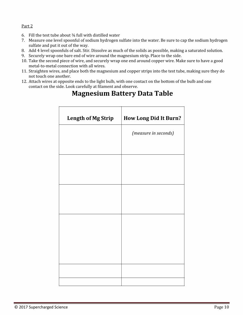
Magnesium Battery Data Table
Length of Mg Strip How Long Did It Burn?
(measure in seconds)
© 2017 Supercharged Science Page 11
Exercises Answer the questions below:
1. Explain two things that happen when magnesium burns.
2. Why do people need to be extra careful when burning magnesium?
3. How did magnesium and copper produce an electrical current in the battery experiment?
© 2017 Supercharged Science Page 12
Exercises
1. Explain two things that happen when magnesium burns. (It combines with oxygen to produce magnesium oxide, and it combines with nitrogen to produce magnesium nitride.)
2. Why do people need to be extra careful when burning magnesium? (It can’t be put out with a CO2 fire extinguisher, the bright light is harmful to eyes; the light contains ultraviolet light which is dangerous
to eyes; if it gets on the skin it will burn to it; it is not safe to inhale magnesium fumes.)
3. How did magnesium and copper produce an electrical current in the battery experiment? (The magnesium strip takes on a negative charge and the copper strip takes on a positive charge. A flow of
electrons run through the wire from negative charge to positive charge, which lights up the bulb.)
Closure: Before moving on, ask your students if they have any recommendations or unanswered questions that
they can work out on their own. Brainstorming extension ideas is a great way to add more science studies to your class time.
© 2017 Supercharged Science Page 13
FRUIT BATTERY
In the battery, there are two different electrodes (called terminals), and when those are connected to wires, an electric field happens between them, pulling the positive charges toward the negative terminal and negative charges toward the positive terminal.
© 2017 Supercharged Science Page 14
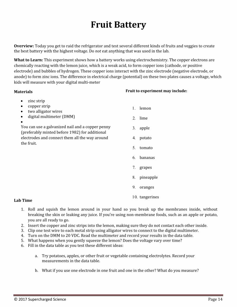
Fruit Battery
Overview: Today you get to raid the refrigerator and test several different kinds of fruits and veggies to create the best battery with the highest voltage. Do not eat anything that was used in the lab.
What to Learn: This experiment shows how a battery works using electrochemistry. The copper electrons are
chemically reacting with the lemon juice, which is a weak acid, to form copper ions (cathode, or positive
electrode) and bubbles of hydrogen. These copper ions interact with the zinc electrode (negative electrode, or
anode) to form zinc ions. The difference in electrical charge (potential) on these two plates causes a voltage, which
kids will measure with your digital multi-meter
Materials
zinc strip copper strip two alligator wires digital multimeter (DMM)
You can use a galvanized nail and a copper penny
(preferably minted before 1982) for additional
electrodes and connect them all the way around
the fruit.
Lab Time
Fruit to experiment may include:
lemon
lime
apple
potato
tomato
bananas
grapes
pineapple
oranges
tangerines
1. Roll and squish the lemon around in your hand so you break up the membranes inside, without
breaking the skin or leaking any juice. If you’re using non-membrane foods, such as an apple or potato,
you are all ready to go.
2. Insert the copper and zinc strips into the lemon, making sure they do not contact each other inside. 3. Clip one test wire to each metal strip using alligator wires to connect to the digital multimeter. 4. Turn on the DMM to 20 VDC. Read the multimeter and record your results in the data table. 5. What happens when you gently squeeze the lemon? Does the voltage vary over time? 6. Fill in the data table as you test these different ideas:
a. Try potatoes, apples, or other fruit or vegetable containing electrolytes. Record your measurements in the data table.
b. What if you use one electrode in one fruit and one in the other? What do you measure?
© 2017 Supercharged Science Page 15
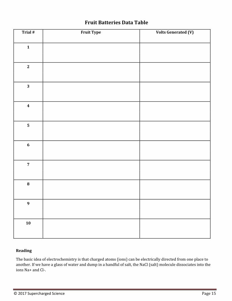
Fruit Batteries Data Table
Trial # Fruit Type Volts Generated (V)
1
2
3
4
5
6
7
8
9
10
Reading
The basic idea of electrochemistry is that charged atoms (ions) can be electrically directed from one place to
another. If we have a glass of water and dump in a handful of salt, the NaCl (salt) molecule dissociates into the
ions Na+ and Cl-.
© 2017 Supercharged Science Page 16
When we plunk in one positive electrode and one negative electrode and crank up the power, we find that
opposites attract: Na+ zooms over to the negative electrode and Cl- zips over to the positive. The ions are
attracted (directed) to the opposite electrode and there is current in the solution.
Electrochemistry studies chemical reactions that generate a voltage and vice versa (when a voltage drives a
chemical reaction), called oxidation and reduction (redox) reactions. When electrons are transferred
between molecules, it’s a redox process
Fruit batteries use electrolytes (solution containing free ions, like salt water or lemon juice) to generate a
voltage. Think of electrolytes as a material that dissolves in water to make a solution that conducts
electricity. Fruit batteries also need electrodes made of conductive material, like metal. Metals are
conductors not because electricity passes through them, but because they contain electrons that can move.
Think of the metal wire like a hose full of water. The water can move through the hose. An insulator would
be like a hose full of cement – no charge can move through it.
You need two different metals in this experiment that are close, but not touching inside the solution. If the
two metals are the same, the chemical reaction doesn’t start and no ions flow and no voltage is generated –
nothing happens.
This experiment produces around one volt of electricity, and the amps are in the micro-to-milli scale. For
comparison, you’ll need about 557 lemons to light a standard flashlight bulb.
Exercises
1. What kinds of fruit make the best batteries?
2. What happens if you put one electrode in one fruit and one electrode in another?
© 2017 Supercharged Science Page 17
3. What happens if you stick multiple electrode pairs around a piece of fruit, and connect them in series
(zinc to copper to zinc to copper to zinc…etc.) and measure the voltage at the start and end electrodes?
© 2017 Supercharged Science Page 18
Answers to Exercises: Fruit Battery
1. What kinds of fruit make the best batteries? (Citrus, because of the acid.)
2. What happens if you put one electrode in one fruit and one electrode in another? (The ions are not able to be attracted to the different electrodes, so there’s no current flowing.)
3. What happens if you stick multiple electrode pairs around a piece of fruit, and connect them in series (zinc to copper to zinc to copper to zinc…etc.) and measure the voltage at the start and end electrodes?
(You’ll get a high voltage at first, which runs out more quickly than using only a single pair.)
© 2017 Supercharged Science Page 19
SOLAR BATTERY
Moving the positive charge from the positive to negative terminal would be with the electric field, so the charge would experience a decrease in potential energy as it moved through an external circuit. (You’ve noticed that we’re only talking about positive test charges here in order to determine which end of the battery is high and which end is low.) This is a really neat experiment on how to make your own solar battery. If you don’t have time or copper flashing for this one, you can just skip doing it but be sure to watch it just for fun…
© 2017 Supercharged Science Page 20
Solar Battery
Overview: This is a favorite experiment of mine, since it really demonstrates the photoelectric effect in a useful way. Here’s the deal: electrons can be either free or attached to the atom, and when you hit a metal place with UV light, some of the attached electrons break free and start current flowing in a circuit.
What to Learn: This lesson will help you learn how solar energy reaches the earth in the form of radiation and takes multiple forms, mostly visible light.
Materials
½ sq. foot of copper flashing sheet (check the scrap bin at a hardware store) Alligator clip leads (RS#278-1156) Multimeter (Radio Shack #22-810) Electric stove (not gas) Large plastic 2L soda bottle ¼ cup salt Sandpaper & sheet metal shears
Lab Time
1. First, we’ll prepare the copper. Use the metal shears to cut the sheet so that it fits on top of the electric burner. Be careful, the edges will be sharp!
2. Wash the sheet very carefully with soap and water on both sides. Once it’s dry, use the sandpaper to scrub off any loose particles. Take your time and scrub it all over on both sides.
3. Place the copper on the burner and turn it to the highest setting. Leave it for about a half hour. Watch the copper for the first few minutes. What do you notice?
4. You can prepare your water bottle while the sheet is cooking. Cut the neck off the bottle. 5. After cooking, turn off the burner and allow the copper to cool on the burner for another twenty
minutes. It will shrink and you should notice a black layer which may flake off. We want the layer
underneath the black layer. Wash the copper to remove any larger black pieces.
6. Cut the sheet in two, and then bend the sheet so that it can fit into the bottle. We want the smoothest side
to face outward. Take a fresh, uncooked piece of copper and place it inside. It’s important that the two
sheets don’t touch.
7. Take some salt and pour it in there. Pour water into the bottle, leaving about an inch of air in the top of the bottle. Stir it up with a spoon so that the salt and water form a solution.
8. Turn on your multimeter, and attach the positive side to the uncooked side of copper, and the negative to the cooked side of copper. Set the meter to read amps.
9. Read the meter in both sunlight and shade. What do you notice? Record your data in the worksheet.
© 2017 Supercharged Science Page 21
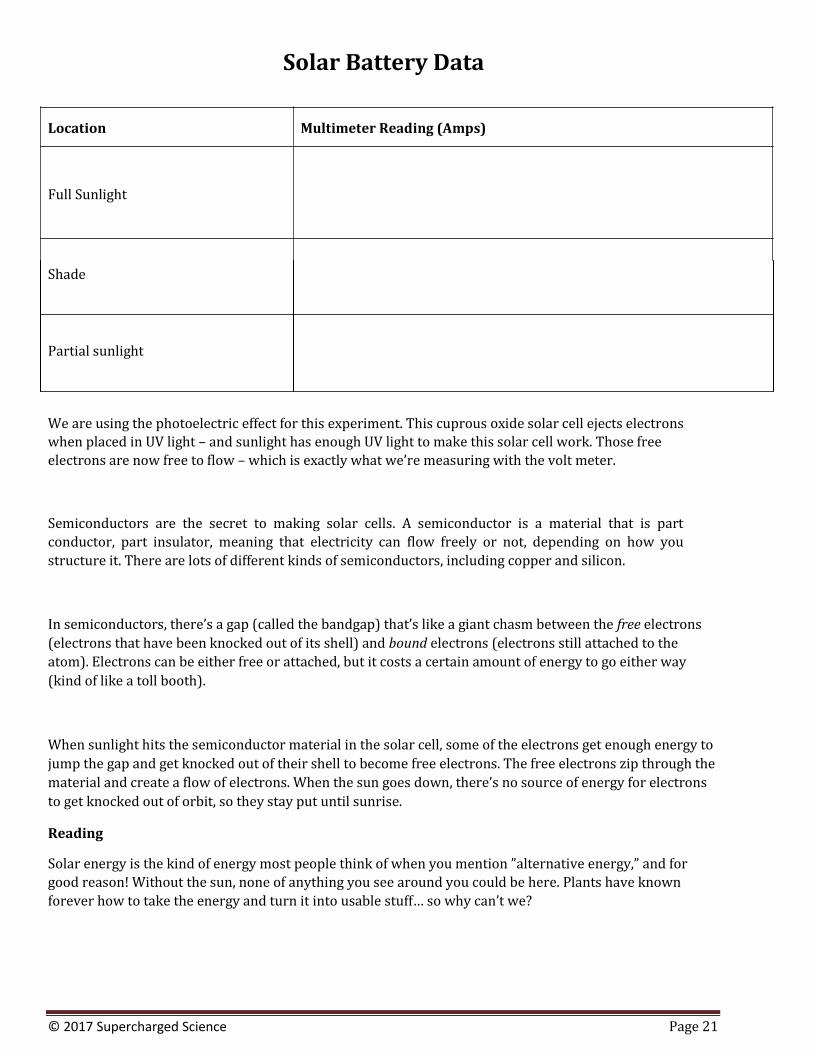
Solar Battery Data
Location Multimeter Reading (Amps)
Full Sunlight
Shade
Partial sunlight
We are using the photoelectric effect for this experiment. This cuprous oxide solar cell ejects electrons when placed in UV light – and sunlight has enough UV light to make this solar cell work. Those free
electrons are now free to flow – which is exactly what we’re measuring with the volt meter.
Semiconductors are the secret to making solar cells. A semiconductor is a material that is part
conductor, part insulator, meaning that electricity can flow freely or not, depending on how you
structure it. There are lots of different kinds of semiconductors, including copper and silicon.
In semiconductors, there’s a gap (called the bandgap) that’s like a giant chasm between the free electrons
(electrons that have been knocked out of its shell) and bound electrons (electrons still attached to the
atom). Electrons can be either free or attached, but it costs a certain amount of energy to go either way
(kind of like a toll booth).
When sunlight hits the semiconductor material in the solar cell, some of the electrons get enough energy to
jump the gap and get knocked out of their shell to become free electrons. The free electrons zip through the
material and create a flow of electrons. When the sun goes down, there’s no source of energy for electrons
to get knocked out of orbit, so they stay put until sunrise.
Reading
Solar energy is the kind of energy most people think of when you mention ”alternative energy,” and for
good reason! Without the sun, none of anything you see around you could be here. Plants have known
forever how to take the energy and turn it into usable stuff… so why can’t we?
© 2017 Supercharged Science Page 22
The truth is that we can. While normally it takes factories the size of a city block to make a silicon solar cell,
we’ll be making a copper solar cell after a quick trip to the hardware store. We’re going to modify the
copper into a form that will allow it to react with sunlight the same way silicon does. The image shown here
is the type of copper we’re going to make on the stovetop.
This solar cell is a real battery, and you’ll find that even in a dark room you’ll be able to measure a tiny amount of current. However, even in bright sunlight, you’d need 80 million of these to light a regular incandescent bulb.
Exercises Answer the questions below:
1. The sunlight causes the electrons to flow from the cuprous oxide because of:
a. Photosynthesis
b. The electromagnetic spectrum
c. The photoelectric effect
d. The photochemical principle
2. What material do most solar cells use instead of copper?
3. What part of the electromagnetic spectrum is most active in this experiment?
a. Visible Light
b. Ultraviolet Light
c. Gamma Rays
d. Microwaves
4. When you read amps, you read:
a. Current
b. Voltage
c. Power Draw
d. Work
© 2017 Supercharged Science Page 23
Answers to Exercises: Solar Battery
4. The sunlight causes the electrons to flow from the cuprous oxide because of the: (photoelectric effect)
5. What material do most solar cells use instead of copper? (silicon)
6. What part of the electromagnetic spectrum is most active in this experiment? (UV light)
7. When you read amps, you read: (current)
© 2017 Supercharged Science Page 24
SALTY BATTERY
In an electrical circuit, the energy starts in the battery as chemical energy which is used to do work on a positive test charge to move it from the lower to a higher potential as it goes through the battery, and then it goes back to a lower potential as it moves through an external circuit (like wires and lights) until it hits the low potential side again and then it gets moved back up to the high potential through the battery, over and over and over again. The energy is being transformed from chemical to electrical, so we cay that batteries are electrochemical cells.
© 2017 Supercharged Science Page 25
Salty Battery
Overview: In the last experiment (Fruit Batteries), we experimented with different electrolyte solutions for the electrodes. This time, we’re keeping the solution the same, but changing the electrodes.
What to Learn: The basic idea of electrochemistry is that charged atoms (ions) can be electrically directed from
one place to the other. If we have a glass of water and dump in a handful of salt, the NaCl (salt) molecule
dissociates into the ions Na+ and Cl-. When we plunk in one positive electrode and one negative electrode and add
electricity, we find that opposites attract: Na+ zooms over to the negative electrode and Cl- zips over to the
positive. The ions are attracted (directed) to the opposite electrode and there is current in the solution.
Materials
water salt distilled white vinegar Goggles and gloves if you have an adult to
handle bleach (do not handle this yourself – your adult will do this part for you)
Disposable cup Popsicle stick
Lab Time
Electrodes to experiment may include:
real silverware (not stainless) shiny nail (galvanized) dull nail (iron) wood screw (brass) large paper clip copper penny or copper pipe graphite from inside a pencil 2 alligator wires digital multimeter (DMM)
1. Fill your cup partway with water. 2. Add a teaspoon of vinegar. 3. Add a teaspoon of salt. 4. Optional: add a couple of drops of bleach, cap it and put it away out of reach of kids. If you are using
bleach, make sure every kid is wearing a pair of goggles. 5. Connect the nail with one alligator clip lead. 6. Connect the penny with another alligator clip lead. 7. Dip both nail and penny in the water, and make sure they are not touching each other. 8. Connect the other ends of alligator clip leads to the probes on the DMM, one alligator wire to each probe. 9. Turn on the DMM to 20 VDC. What do you read? Write it here:_____________________________________________ 10. What happens if you pull the two electrodes as far apart from each other as possible? What happens to
your voltage? Write it here:
_____________________________________________________________________________________________
© 2017 Supercharged Science Page 26
11. Replace the penny with a paperclip, and dip it in the solution. What do you read? Write it in your data table.
12. What about a brass screw? What other things can you try? What different combinations are there to test? Fill in the data table with your measurements.
Reading
Using ocean water (or make your own with salt and water), you can generate enough power to light up your
LEDs, sound your buzzers, and turn a motor shaft. We’ll be testing out a number of different materials such as
copper, aluminum, brass, iron, silver, zinc, and graphite in a small sample of salt water to find out which works
best for your solution.
Electrochemistry studies chemical reactions that generate a voltage and vice versa (when a voltage drives a
chemical reaction), called oxidation and reduction (abbreviated ”redox”) reactions. When electrons are
transferred between molecules, it’s a redox process.
Electrolytes (a solution containing free ions, like salt water or lemon juice) can be used to generate a voltage.
Think of electrolytes as a material that dissolves in water to make a solution that conducts electricity. Did you
notice how in Lesson #23: Fruit Batteries, we also needed electrodes made of conductive material, like metal?
Metals are conductors not because electricity passes through them, but because they contain electrons that can
move. Think of the metal wire like a hose full of water. The water can move through the hose. An insulator would
be like a hose full of cement – no charge can move through it. You need two different metals in this experiment that
are close, but not touching inside the solution. If the two metals are the same, the chemical reaction doesn’t start
and no ions flow, no voltage is generated… nothing happens. But don’t take my word for it – try it for yourself!
Exercises
1. Which combination gives the highest voltage?
2. What happens if you use two strips of the same material?
3. What would happen if we used non-metal strips?
© 2017 Supercharged Science Page 27
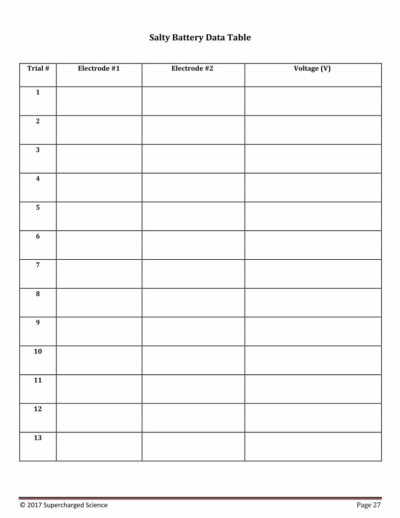
Salty Battery Data Table
Trial # Electrode #1 Electrode #2 Voltage (V)
1
2
3
4
5
6
7
8
9
10
11
12
13
© 2017 Supercharged Science Page 28
14
15
16
17
18
19
20
© 2017 Supercharged Science Page 29
Answers to Exercises: Salty Battery
1. Which combination gives the highest voltage? (Check data for result.)
2. What happens if you use two strips of the same material? (You won’t have a difference. These copper ions
interact with the zinc electrode to form zinc ions. The copper electrons are chemically reacting with the lemon
juice to form copper ions. The difference in electrical charge (potential) on these two plates causes a voltage.)
3. What would happen if we used non‐metal strips? (They don’t break into ions, and don’t work.)
© 2017 Supercharged Science Page 30
TAKING A COLLEGE CLASS IN ELECTRICITY
Have you ever wondered what college will be like? Here’s a video from a professor at MIT on electrostatics, specifically the electric field and the electric potential. It’s a full class lecture, so don’t worry if you get a little lost with the calculations on the chalkboard. Just sit back and enjoy watching learning from someone other than me (Aurora) so you get more than one perspective on the subject.
© 2017 Supercharged Science Page 31
VOLTAGE
Electric potential is defined as the amount of potential energy per charge. Watch this next video and see if you can quickly determine the work done on the charge and where the electric potential is the greatest…
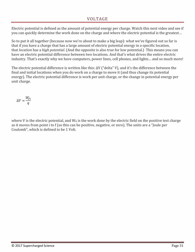
So to put it all together (because now we’re about to make a big leap): what we’ve figured out so far is that if you have a charge that has a large amount of electric potential energy in a specific location, that location has a high potential. (And the opposite is also true for low potential.) This means you can have an electric potential difference between two locations. And that’s what drives the entire electric industry. That’s exactly why we have computers, power lines, cell phones, and lights… and so much more! The electric potential difference is written like this: ΔV (“delta” V), and it’s the difference between the final and initial locations when you do work on a charge to move it (and thus change its potential energy). The electric potential difference is work per unit charge, or the change in potential energy per unit charge.
where V is the electric potential, and Wfi is the work done by the electric field on the positive test charge as it moves from point i to f (so this can be positive, negative, or zero). The units are a “Joule per Coulomb”, which is defined to be 1 Volt.
© 2017 Supercharged Science Page 32
BALLOON RISING IN THE AIR
This problem is a fun one to solve! Let’s find out how much static charge build up there is on a balloon rising into the atmosphere.
© 2017 Supercharged Science Page 33
POINT CHARGE
Imagine you have a positive test charge in an electric field and you move it from one point to another. When you move it, the charge against the electric field, you have to do work on it using an external force, like your hand pushing it along the path. The work done by your hand on the charge will increase the potential energy and also cause a difference in the electric potential between the start and finish locations. If the electric potential difference between the start and finish is 10 volts, then one Coulomb of charge will increase by 10 Joules of potential energy when you push the charge from start to finish. This is what voltage is.
© 2017 Supercharged Science Page 34
INSIDE GOLD
Now Let’s take a look at the nucleus of a gold atom, specifically at the potential on the surface. There are 79 protons inside…
© 2017 Supercharged Science Page 35
SKIING DOWN A MOUNTAIN
Now imagine a simple circuit that uses a light bulb (or LED) and a battery. The battery provides the energy to do work on the charges to move it from the negative to the positive terminal. Once the charge is at the high potential (the plus side of the battery), it’s like taking a chair lift to the top of a mountain… it is now ready to ski down the mountain with little to no effort. So once the charge is at the high potential terminal, it naturally flows through the wires to the low potential terminal. The ski lift is doing work to get you up the mountain against the nature of the gravitational field the same way the battery is doing work on the electric charge moving it from a low to high potential.
The battery is the internal circuit, because energy is given to the charge. The external circuit is the part where the charge loses energy by moving along the wires and lighting up LEDs, making buzzers sound, turning motors, etc. Each element in the circuit takes energy from the charge (even the wire itself) and transforms it into something useful or not. Light, sound, motion are all useful forms of energy. The heat coming from an incandescent light bulb would be non-useful thermal energy. As the charge moves through a device, it starts out at a higher energy than it leaves the device with, so there’s a voltage drop across that circuit element. The charge returns to the low potential side of the battery at zero volts and is ready to be pumped back up to the high voltage positive terminal.
© 2017 Supercharged Science Page 36
REVIEW ON ELECTRIC POTENTIAL DIFFERENCE
To review, an electron moving in an electric field would change the potential energy of the electron, and the way it moves through the field determines whether it gains or loses energy. When you turn on a flashlight, the battery supplies energy to move the charge through the battery and makes an electric potential difference so the charge can then have enough energy to move through the wires and light bulb of your flashlight. The battery doesn’t add protons, neutrons, or electrons to the circuit. The electrons that move are already in the wire itself. Charge doesn’t get used up in the circuit, only energy is used up.
© 2017 Supercharged Science Page 37
INSIDE URANIUM
Let’s look at two protons inside the nucleus of a uranium atom…
© 2017 Supercharged Science Page 38
ELECTRIC CURRENT
Imagine you have two metal plates that are parallel to each other, and one is positively charged ad the other is negatively charged. The direction of the electric field created by these two charged places is from the positive toward the negative plate. (Imagine placing a positive test charge int he field… which way would it go? Away from the positive plate and toward the negative plate… so that’s the direction of the electric field.) Now imagine connecting the two plates with a metal wire. What do you think would happen? The positive charges on the positive plate would flow toward the negative plate, evening out the charge until they were both at the same charge, and then there is no electric potential difference between the two. It’s like connecting a hose between two cups filled with different levels of water. The water flows out of the cup with more water into the one with less until they both even out. When the charges even out, there not charge flow because there’s no electrical potential difference.
© 2017 Supercharged Science Page 39
ELECTRIC CIRCUITS
If we add another wire that runs through a battery first before returning to the second plate, then we’ve created a closed loop system that will keep the two plates charged. The battery takes the charge on the negative plate and adds energy to it and puts it back on the positive plate, where it is free to drop back down to the negative plate through the wire. If we replace the wire with a bulb filament, when the charge goes through the wire, it will light up the filament and give off light. You’ve just made a simple circuit! An electric circuit is a closed loop that charges move through over and over. Charges moving through the wire is called current. Current is the rate that charge flows, and only flows in a closed, conducting circuit that also has a power source to create an electric potential difference. Without a battery, the LED is not going to light up. If you use string instead of wire, the current isn’t going to flow to the LED. Current flows from plus to minus in a circuit. Electric circuits are useful to move charge from one place to another. When I teach kids how to make a basic circuit using wires, batteries, and LEDs, there’s always a couple of them that completely forget to put the LED in and can’t sure out why just hooking up a wire from plus to minus on the battery doesn’t work. The fact is that in their case, it is working, but not the way they had expected. The charge is moving along the wire and back into the battery, creating a short circuit that will eventually overload (and dangerously burst) the battery. You always need to be powering something, whether it’s a motor, LED, doorbell, or alarm. That something is called a load. In the previous video, the load was the LED. Electric circuits are essentially energy transforming devices.
© 2017 Supercharged Science Page 40
Basic Circuits
Overview: This lab will get you familiar with how to hook up a simple circuit so we can move to more complex stuff soon, like motors, switches, and remote controls. But first…he basics.
What to Learn: Remember when you scuffed along the carpet? You gathered up an electric charge in your body.
That charge was static until you zapped someone else. The movement of electric charge is called electric
current, and is measured in amperes (A). When electric current passes through a material, it does it by electrical
conduction. There are different kinds of conduction, one of which is called metallic conduction, where electrons
flow through a conductor, like metal.
Materials
2 AA batteries AA battery case 2 alligator wires LEDs
Safety Tip: I recommend using the super-cheap kind of batteries (usually labeled “Heavy Duty” or “Super
Heavy Duty”), usually found at dollar stores. These types of batteries are carbon-zinc, which do not contain
acid that can leak and expose you to toxic chemicals. When you short the circuits and overheats the batteries
(which you should expect, by the way), it’s not dangerous. Alkaline batteries (like Energizer and Duracell) will
get super-hot and leak acid, so those aren’t the ones you want to play with.
Lab Time
1. Following the video instructions, use the materials to wire up a simple circuit and get the LED to light up: a. Insert your batteries into the case. Flat side (minus) goes to the spring. b. Attach one alligator clip to each of the metal tips of the wires from the battery case. Make sure
you’ve got a good metal-to-metal connection. You should now have two alligator clips attached to the battery pack.
c. Attach the end of the alligator clips that’s connected to the black wire (negative) from the battery case to the flat side of the LED. It doesn’t matter what color the alligator clip wire is.
d. Attach the other alligator clip that’s connected to the red wire (positive) from the battery case to the longer LED wire. Again, it doesn’t matter what color the alligator clip wire is.
e. Your LED should light up! 2. Once your LED is illuminated, what happens if you take it out and insert it in the opposite way into the circuit? (Reverse the polarity.) Does it still work? 3. Troubleshooting a circuit that doesn’t work:
a. Batteries inserted into the case the wrong way? (Flat side of the battery should go to the metal spring inside the case.)
b. LED is in the circuit the wrong way? Remember, LEDs are picky about plus and minus, meaning that it matters which way they are in the circuit. If you choose a bipolar LED, then you don’t have to worry about this one, since there are two LEDs, one in each direction, in one LED package which will illuminate no matter which way you have it in your circuit. LEDs are polarized.
© 2017 Supercharged Science Page 41
c. Is there a metal-to-metal connection? You’re not grabbing the plastic insulation, are you? Not even a tiny bit? Sometimes kids have the edge of the alligator clip lead propped up on the edge of the plastic insulation, which will make your connection not work.
d. Once in awhile, you’ll get a bad alligator wire. There’s an easy to check this: remove your alligator clip leads from the circuit and touch each of the metal tips from the battery pack wires to the LED wires. If the LED lights up, swap out your alligator clip lead wires for new ones and that should fix it.
Reading
When electric current passes through a material, it does so by electrical conduction. There are different kinds of
conduction, such as metallic conduction, where electrons flow through a conductor, like metal, and also by
electrolysis, where charged atoms called ions flow through liquids (we’ll be getting to that later).
Although we can't see electricity flow through wires, you can certainly see, hear, and feel its effects: the light
bulb flashing on, the hair dryer blowing, the heat generated by a hot wire, and so forth. In order to understand
electricity, though, we’re going to talk about water, because that’s something that you already have experience
with.
Electricity is like water going through a pipe. Imagine you have a big pipe connected in a circle, so it connects
back to itself in a loop. The water needs a pump in order to move through the pipe. Electricity is like the water
going through the pipe, and the battery is like the pump.
Now imagine breaking open your pipe to insert a waterwheel. Seal up the cracks and turn on your pump. Can you
imagine what happens now? When the pump (battery) turns on, the water (electricity) flows through the pipe and
turns the waterwheel. The waterwheel is like your motor or light bulb.
Suppose you add in a valve so you can turn the water on and off through your pipe. What is the valve like in your circuit? It’s just like a switch in a circuit, because it interrupts the flow of electricity.
What would happen if you broke your pipe? Imagine you have a sledgehammer and you smashed open the pipe.
Does it matter which side of the waterwheel you break it on? It does! If you break it before the waterwheel, the
waterwheel won’t turn. If you break it after the waterwheel, it might turn for a minute, but then it will stop
because there’s no more water going into the pump because you busted open the pipe, so the flow stops either
way., That’s what happens when you disconnect one of your wires in your circuit. No more electricity can flow.
Now imagine you’ve got a whole, complete pipe again. What would happen if we take out the pump, turn it
around, and stick it back in again? The water goes the other way! What direction does the waterwheel go? It starts
turning in the opposite direction also.
Some waterwheels are designed to go either forward or backward, while other waterwheels can only move
forward due to the shape of their blades and how they were made. Some electrical components like buzzers and
LEDs are polarized, meaning that they do not work backward. Other electrical components, like motors and light
bulbs, do work forward and backward. When you work with circuits, if you find a component that doesn’t work,
try turning it around in the circuit to see if that fixes it.
© 2017 Supercharged Science Page 42
If you look around the room, do you notice the different kinds of light bulbs you have? You might find a fluorescent bulb, an incandescent light bulb, a neon bulb an LED, or even a halogen lamp. What’s the difference in
how these produce light?
The incandescent light bulb uses a wire that glows when electric current runs through it. To keep the wire from burning itself up, the air is removed from the bulb and replaced with an inert gas. The wire is made from the element tungsten.
Neon bulbs light up because the electrical field excites the gas, which then gives off a pinkish-orange light.
A fluorescent tube is lined with white stuff called phosphor, which gives off light whenever it’s struck by UV rays.
The tube is filled with a gas that gives off UV rays when placed in an electrical field. When the bulb is brought close
to a static charge, electrons rip through the tube and go out the other side. As they go through, they smack into the
gas vapor which releases light rays (UV in a fluorescent tube) that hit the phosphor on the inside of the tube,
which then emits light. Fluorescent lights, or any tube of gas from the noble gases column on the periodic table,
like neon, will also glow in an electrically-charged field.
LED stands for “Light Emitting Diode." They don't have a filament so they don't get hot. They light up by the
movement of electrons in a semiconductor material (more on this later), and they last a long time, like thousands of hours.
For halogen lamps, instead of creating a vacuum like with incandescent bulbs, they fill the bulb with a halogen gas so that the filament will burn brighter. It’s not the gas that’s illuminating, but rather the filament itself.
Exercises
1. What does LED stand for?
2. Does it matter which way you wire an LED in a circuit?
© 2017 Supercharged Science Page 43
3. Does the longer wire on the LED connect to plus (red) or minus (black)?
4. Do you need to hook up batteries to make a neon bulb light up? Why or why not?
5. What's the difference between a light bulb and your LED?
6. What is the difference between a bolt of lightning and the electricity in your circuit?
7. What is the charge of an electron?
© 2017 Supercharged Science Page 44
Answers to Exercises: Basic Circuits
1. What does LED stands for? (“Light Emitting Diode.”)
2. Does it matter which way you wire an LED in a circuit? (Yes, LEDs are polarized.)
3. Does the longer wire on the LED connect to plus (red) or minus (black)? (Longer lead is positive, and the flat side on the lens is negative.)
4. Do you need to hook up batteries to make a neon bulb light up? Why or why not? (No. The neon bulb
(from Lesson #7 will light up from static electricity. No batteries required. The neon lamp requires very
little amps, but high voltage to illuminate, which you can get by charging yourself up. Simply hold one
lead and scuff along the carpet and touch the other lead to your cat's nose. Or hold one lead and slide
down a non‐metal slide.)
5. What's the difference between a light bulb and your LED?
6. What is the difference between a bolt of lightning and the electricity in your circuit? (One one: quantity.)
7. What is the charge of an electron? (Negative)
© 2017 Supercharged Science Page 45
DETECTING CURRENT
You can detect current moving through the wire by bringing a compass needle close to the wire. If the needle deflects, then a charge is present. Try doing this with the simple circuit you just made when it’s both powered on and also when it’s off (no batteries in the circuit). Here’s a way to see the needle deflect a lot by making a galvanometer:
© 2017 Supercharged Science Page 46
Galvanometers
Overview Today is a very important day in your magnetism studies. You will begin to discover how electricity and magnetism cause each other. In the second half of this lab, they’ll get to re-enact one of the most important
scientific discoveries of all time: how magnetism causes electricity.
What to Learn Galvanometers are coils of wire connected to a battery. When current flows through the wire,
it creates a magnetic field. Since the wire is bundled up, it multiplies this electromagnetic effect to create a
simple electromagnet that you can detect with your compass.
Materials
Magnet wire Sandpaper Scissors Compass AA battery case 2 AA batteries 2 alligator clip wires Strong magnet Toilet paper or paper towel tube
Lab Time
1. Wrap the wire 30-50 times around your fingers, making sure your coil is large enough to slide the compass
through. Take one of the ends of the wire and wrap it a couple of times around a section of the circle to
keep the wire from unwinding. Do this for both sides.
2. Remove the insulation from about an inch of each end of the wire. Use sandpaper if you’re using magnet wire.
3. Connect one end of the wire to the battery case wire. 4. While looking at the compass, repeatedly tap the other end of the wire to the battery. You should see
the compass react to the tapping. 5. Switch the wires from one terminal of the battery to the other. Now tap again. Do you see a difference in the
way the compass moves? Write it here:
_________________________________________________________________________________________________________________
6. You just made a simple galvanometer. “Oh boy, that’s great! Hey Bob, take a look! I just made a….a what?!?” I
thought you might ask that question. A galvanometer is a device that is used to find and measure electric
current. “But, it made a compass needle move…isn’t that a magnetic field, not electricity?” Ah, yes, but hold on
a minute. What is electric current…moving electrons. What do moving electrons create…a magnetic field!
By the galvanometer detecting a change in the magnetic field, it is actually measuring electrical current! So, now that you’ve made one let’s use it!
© 2017 Supercharged Science Page 47
7. Take your new piece of wire and wrap this wire tightly and carefully around the end of the paper towel
tube. Do as many wraps as you can while still leaving about 4 inches of wire on both sides of the coil.
You may want to put a piece of tape on the coil to keep it from unwinding. Pull the coil from the paper
towel tube, keeping the coil tightly wrapped. Take one of the ends of the wire and wrap it a couple of
times around a section of the circle to keep the wire from unwinding. Do this for both sides.
8. Remove about an inch of insulation from both ends of the wire using sandpaper. 9. Hook up your new coil with your galvanometer. One wire of the coil should be connected to one wire of
the galvanometer and the other wire should be connected to the other end of the galvanometer. 10. Now move your magnet in and out of the coil. Can you see the compass move? Does a stronger or weaker
magnet make the compass move more? Does it matter how fast you move the magnet in and out of the coil? 11. Taa Daa!!! Ladies and gentlemen you just made electricity!!!!! You also just re-created one of the
most important scientific discoveries of all time. 12. Now, we know that you can’t have an electric field without a magnetic field. You also cannot have a
moving magnetic field without causing electricity in objects that electrons can move in (like wires).
Moving electrons create a magnetic field, and moving magnetic fields can create electric currents.
13. “So, if I just made electricity, can I power a light bulb by moving a magnet around?” Yes, if you moved that magnet back and forth fast enough you could power a light bulb. However, by fast enough, I mean like 1,000 times a second or more! If you had a stronger magnet, or many more coils in your wire, then you could make a greater amount of electricity each time you moved the magnet through the wire.
14. Believe it or not, most of the electricity you use comes from moving magnets around coils of wire!
Electrical power plants either spin HUGE coils of wire around very powerful magnets or they spin very
powerful magnets around HUGE coils of wire. The electricity to power your computer, your lights, your air
conditioning, your radio or whatever, comes from spinning magnets or wires!
15. “But what about all those nuclear and coal power plants I hear about all the time?” Good question. Do you
know what that nuclear and coal stuff does? It gets really hot. When it gets really hot, it boils water. When it
boils water, it makes steam and do you know what the steam does? It causes giant wheels to turn. Guess
what’s on those giant wheels. That’s right, a huge coil of wire or very powerful magnets! Coal and nuclear
energy basically do little more than boil water. With the exception of solar energy almost all electrical
production comes from something huge spinning really fast!
16. Draw out your experiment, showing how the magnet creates electricity and where/how that electricity creates magnetism. Label all the different parts of your experiment:
Reading
Now we’ve covered the fact that magnetic fields are caused by electrons moving in the same direction. Up to
this point, we’ve been focusing on magnetism being caused by an unequal number of electrons spinning in the
same direction in an atom.
If an atom has more electrons spinning in one direction than in the other direction, that atom will have a magnetic
field. When bunches of these atoms get together, we have a permanent magnet. Now we’re going to talk about
what happens if we force electrons to move.
This is one of the most important scientific discoveries of all time. One story about this discovery goes like this:
© 2017 Supercharged Science Page 48
A science teacher doing a demonstration for his students (Can you see why I like this story?) noticed that as he
moved a magnet, he caused one of his instruments to register the flow of electricity. He experimented a bit
further with this and noticed that a moving magnetic field can actually create electrical current, thus tying the
magnetism and the electricity together.
Before that, they were seen as two completely different phenomena! Now we know that you can’t have an
electric field without a magnetic field. You also cannot have a moving magnetic field without causing electricity in
objects that electrons can move in (like wires). Moving electrons create a magnetic field and moving magnetic
fields can create electric currents.
“So, if I just made electricity, can I power a light bulb by moving a magnet around?”
Yes, if you moved that magnet back and forth fast enough you could power a light bulb. However, by fast enough,
I mean like 1000 times a second or more! If you had a stronger magnet, or many more coils in your wire, then you
could make a greater amount of electricity each time you moved the magnet through the wire.
Believe it or not, most of the electricity you use comes from moving magnets around coils of wire! Electrical power
plants either spin HUGE coils of wire around very powerful magnets or they spin very powerful magnets around
HUGE coils of wire. The electricity to power your computer, your lights, your air conditioning, your radio or
whatever, comes from spinning magnets or wires!
“But, what about all those nuclear and coal power plants I hear about all the time?”
Good question. Do you know what that nuclear and coal stuff does? It gets really hot. When it gets really hot, it
boils water. When it boils water, it makes steam and do you know what the steam does? It causes giant wheels to
turn. Guess what’s on those giant wheels. That’s right, a huge coil of wire or very powerful magnets!
Coal and nuclear energy basically do little more than boil water. With the exception of solar energy almost all electrical production comes from something huge spinning really fast!
Exercises
1. Why didn’t the coil of wire work when it wasn’t hooked up to a battery? What does the battery do to the coil of wire?
2. How does a moving magnet make electricity?
© 2017 Supercharged Science Page 49
3. What makes the compass needle deflect in the second coil?
4. Does a stronger or weaker magnet make the compass move more?
5. Does it matter how fast you move the magnet in and out of the coil?
© 2017 Supercharged Science Page 50
Answers to Exercises: Galvanometers
1. Why didn’t the coil of wire work when it wasn’t hooked up to a battery? What does the battery do to the coil of
wire? (The wire is just wire until you have electricity passing through it. The electricity causes a small magnetic
field around the wire. When you bundle and coil the wire up, you multiply this effect to create an
electromagnet.)
2. How does a moving magnet make electricity? (If you moved that magnet back and forth along a coil of wire fast enough you could power a light bulb. However, by fast enough, I mean like 1,000 times a second or more!)
3. What makes the compass needle deflect in the second coil? (When a magnet is moved in and out of the first
coil quickly, it creates a current in the wire which travels to the second coil of wire, turning the second one
into an electromagnet. An electromagnet is a magnet that you can turn on and off with electricity. Since the
compass is affected by magnets, this tells us that the compass is near a magnetic field when it deflects,
which means that the wire is creating a magnetic field.)
4. Does a stronger or weaker magnet make the compass move more? (Stronger)
5. Does it matter how fast you move the magnet in and out of the coil? (Yes – the faster you move it, the more the needle deflects.)
© 2017 Supercharged Science Page 51
CONDUCTIVITY
Certain materials conduct electricity better than others. Silver, for example, is one of the best electrical conductors on the planet, followed closely by copper and gold. Most scientists use gold contacts because, unlike silver and copper, gold does not tarnish (oxidize) as easily. Gold is a soft metal and wears away much more easily than others, but since most circuits are built for the short term (less than 50 years of use), the loss of material is unnoticeable. Modify your basic LED circuit into a Conductivity Circuit by removing one clip lead from the battery and inserting a third clip lead to the battery terminal. The two free ends are your new clips to put things in from the grab bag. Try zippers, metal buttons, barrettes, water from a fountain, the fountain itself, bike racks, locks, doorknobs, unpainted benches… you get the idea!
© 2017 Supercharged Science Page 52
Conductivity Testers
Overview: Today you get to wire up a simple circuit and test a variety of objects to figure out if they are insulators or conductors of electricity.
What to Learn: Take special note as to which kinds of materials are insulators and which are conductors of
electricity. Metals are conductors not because electricity passes through them, but because they contain
electrons that can move.
Materials
2 AA batteries AA battery case 3 alligator wires LEDs
Lab Time
1. it’s time to wire up your detector. Here’s what you need to do: a. Remove one of the alligator clips from the LED (it doesn’t matter which one) and let it dangle. b. Add a third alligator clip to the LED – right in the same spot as the one you just removed. The
other end should be dangling also. c. Hold the circuit by the two dangling alligator clips, and touch their tips together. The LED
should light up. d. Break contact and the LED goes dark. Touch them together again and the LED lights up. On. Off. On.
Off. On. This is the world’s simplest switch. e. Now touch each of the two alligator clips to either side of an object you think will
conduct electricity. What did you test and what happened?
_______________________________________________________________________________________________________________
_______________________________________________________________________________________________________________
_______________________________________________________________________________________________________________
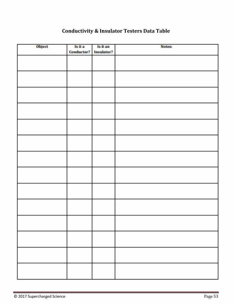
2. Fill out the data table:
© 2017 Supercharged Science Page 53
Conductivity & Insulator Testers Data Table
© 2017 Supercharged Science Page 54
Reading
Metals are conductors not because electricity passes through them, but because they contain electrons that can move. An insulator does not allow electrons to move.
Think of the metal wire like a hose full of water. The water can move through the hose. An insulator would be like a hose full of cement - no charge can move through it.
All metals conduct electricity: however, some metals like copper and gold conduct better than others because
they have less internal resistance (which relates to how the metal is structured.) Metals have free electrons which
can move from atom to atom, allowing the electricity to conduct through them. Paper, rubber, and plastics make
great insulators, because sometimes you don’t want electricity to flow unless you say so. We’re going to talk about
switches when we make our burglar alarms later on.
Exercises
1. Name six materials that are electrically conductive.
2. What kinds of materials are conductors and insulators?
© 2017 Supercharged Science Page 55
3. Can you convert an insulator into a conductor? How?
4. Name four instances when insulators are a bad idea to have around.
5. When are insulators essential to have?
© 2017 Supercharged Science Page 56
Answers to Exercises: Conductivity Testers
1. Name six materials that are electrically conductive. (Soda cans, quarters, paper clips, braces, unpainted eyeglasses, and your tongue.)
2. What kinds of materials are conductors and insulators? (Materials with free electrons, like metals, are conductors. Insulators are like paper, ceramics, and rubber.)
3. Can you convert an insulator into a conductor? How? (Yes, that’s what a semiconductor is. It’s like a
switch in a black box. Sometimes it conducts and sometimes it doesn’t. If it’s a dimmer switch, then it conducts to different degrees depending on the position of the dimmer.)
4. Name four instances when insulators are a bad idea to have around. (When you need to conduct electricity,
like to a bulb, motor, relay, buzzer, etc. Also when static charge can harm a circuit, you need a way to
discharge regularly to avoid build‐up.)
5. When are insulators essential to have? (When you want to turn off a light.)
© 2017 Supercharged Science Page 57
REQUIREMENTS FOR A CIRCUIT
You need two important things for an electric circuit: first you need a closed conductive path that goes from the positive to the negative terminal of the battery. When I teach this activity to kids, there’s always a couple that try to light up the LED just using the LED and wires (they forget about the battery completely!) You always need a power source in the circuit in order for charges to flow. The charges only flow through something that conducts electricity. Sometimes kids forget about the conductive part, and just try to touch the plastic coating on the wires to the LED and are frustrated when it doesn’t work right. It must be a closed conductive loop. The second thing is that there needs to be an electric potential difference across the two ends of the circuit. (You can think of the ends as the ends that are connected to the battery.) Because it takes energy to move the charge from a low to a high potential (remember how it takes energy to go up a flight of stairs?), there needs to be something that supplies the charges with the energy they need to go from a low to a high electric potential so then they can move through the circuit on their own. As the charge moves though the circuit, it loses energy until it reaches the negative terminal at zero energy. Then the battery gives that charge energy and it moves back up to the positive terminal at high energy and does it all over again. The battery pumps up the charges and creates an electric potential difference across the two ends of the circuit. In your house, the electric outlet that you plug appliances and lamps into is the electric potential difference. The three holes in the outlet are hot, neutral, and ground.
The hot terminal is the smaller one on the upper right, and this has the highest potential. Neutral is the larger one on the upper left, and it is the return path for current (and should always be considered to be high potential. It’s unfortunately pretty common for hot and neutral wiring to be reversed, because the outlet still works if it is.) Ground is the roundish one at the bottom and is there for safety. Ground and neutral are connected together back at the box, and they give electricity the quickest and simplest way back to the low potential. An ungrounded device (including extension cords) can be dangerous if there’s no path to ground except through you.
The electrical outlet in US homes supplies 110-120 volts of voltage and 15-20 amps of current. On the other hand, a AA battery has 1.5 volts and about 50 mA (that;s 0.050 amps), depending on the type of battery and what kind of load you are putting on it.
And just in case you’re considering poking something into the outlet, over 4,000 people every year are in the emergency room for injuries that have to do with sticking something other than a plug into an electrical outlet, about one third of them are kids under 18 years old. And those are just the ones you made it to the hospital… some were not as lucky and never made it at all. The current can kill you because you’re made up mostly of water, which makes it a really good conductor of electricity. Electricity is always looking for the easiest way to ground, and though you is one of those ways and the amount of current that passes through you is enough to stop your heart and damage your cells. Bottom line: the only thing you should put into an outlet is a plug.
© 2017 Supercharged Science Page 58
WATER ANALOGY
This is a recording of a recent live teleclass I did with thousands of kids from all over the world. I’ve included it here so you can participate and learn, too! If you’ve done the previous section on Static Electricity, you’ve already seen this, but I wanted to include in here in case you’ve been skipping around so you understand the water analogy that is often used to model how electricity goes through a circuit: Current is measured in amps, and is a measure of how much charge is flowing through the circuit at a certain point. We use the letter I to mean current when we’re doing calculations on paper, and it’s important to remember that current is like velocity in that it’s a rate.Just like velocity is the change in position per unit time, current is the amount of charge per unit time: I = Q/t. This means that one amphere (amp) is one coulomb per second.
© 2017 Supercharged Science Page 59
FRANKLIN’S MISTAKE
If this next part is too confusing, just skip over it. I did want to let you know (for those of you who have spotted it already) that there’s a big problem with the positive test charge model we’ve been using. Well, it’s kind of a problem, but not really a big one once you get used to the idea. When we determined which one is the high and low potential (the plus and minus on a battery), we assumed that the test charge was positive. The particles that move charge through the wires are actually negatively, not positively, charged. We’ve been dealing with just positive charges so far, and now we’re going to mix things up a bit since electrons are in fact, negative. This means that current actually goes from the negative terminal to the positive terminal because that charge is being carried by electrons. Note that charge carriers don’t have to be electrons (they can also be positively charged or both traveling simultaneously in opposite directions!) It was actually one of Ben Franklin’s not-so-great moments when he arbitrarily assigned the direction of electric current the way we think about it today, which is going from the positive to the negative terminal. Electrons actually move in the opposite direction! BUT in the real world, we all think about current flowing from plus to minus (even though in reality its the opposite direction). Just file it away in your mind in case it ever comes up (which it probably won’t) that you would need to know the actual direction the electrons are moving in a circuit (which most people don’t need to know or care about).
© 2017 Supercharged Science Page 60
CHARGE CARRIERS ARE NOT USED UP
In electric circuits, the charge carriers are electrons, which are already inside the wire itself. The battery doesn’t add extra electrons to the circuit to make it go… the electrons inside the wires are already there. The battery provides an electric potential difference that signals the electrons to start moving, and this signal travels at the speed of light (or close to it), and then the electrons start moving (quite a bit slower than the speed of light). This means that electrons don’t have to start at the battery and them go all the way to the light before the light bulb lights up, because the electrons inside the filament itself are the ones that start glowing when they get the signal to start moving. All electrons everywhere start moving as soon as they get that signal from the battery, like like water flowing in the hose that we saw in the teleclass video. The electrons themselves don’t get used up, but rather the energy carried by the electrons is transformed to other forms of energy (including heat, light, sound, motion, etc.). The charge itself doesn’t transform or get used up, just the energy itself. Kids use up their energy as they run, play, and jump , and need to refuel before they can go back in the afternoon to the playground. The kids don’t get used up, but rather the energy the kid is carrying is being transformed from chemical energy int the food to motion energy , and needs to be replenished when the kid runs out of energy.
© 2017 Supercharged Science Page 61
SWITCHES
When you turn on a switch, it’s difficult to really see what’s going on… which is why we make our own from paperclips, brass fasteners, and index cards. You can see the circuit on both sides of the card, so it makes sense why it works (especially after doing ‘Conductivity Testers’). SPST stands for Single Pole, Single Throw, which means that the switch turns on only one circuit at a time. This is a great switch for one of the robots we’ll be making soon, as it only needs one motor to turn on and off. Think of this switch like a train track. When you throw the switches one way, the train (electrons) can race around the track at top speed. When you turn the switch to the OFF position, it’s like a bridge collapse for the train – there’s no way for the electrons to jump across from the brass fastener to the paper clip. When you switch it to the ON position (both sides), you’ve rebuilt the bridges for the train (electrons). Did you notice how the paperclip works with the brass fasteners to signal the electrons to power the LED? That’s the signal we’re talking about! Troubleshooting: The two tabs on the back of the motor are the places to clip in the power from the battery pack. Since these motors spin quickly and the shaft is tiny, add a piece of tape to the shaft to see the spinning action more clearly.
© 2017 Supercharged Science Page 62
Switches & Motors
Overview: When you turn on a switch, it’s difficult to really see what’s going on. So you’re going to make your own from paperclips, brass fasteners, and index cards. And you get to play with real motors, too.
What to Learn: Think of this switch like a train track. When you throw the switches one way, the train
(electrons) can race around the track at top speed. When you turn the switch to the OFF position, it’s like a bridge
collapse for the train – there’s no way for the electrons to jump across from the brass fastener to the paper clip.
When you switch it to the ON position (both sides), you’ve rebuilt the bridges for the train (electrons).
Materials
2 AA batteries AA battery case 2 alligator wires 1.5-3V DC hobby motor 1 index card 2 brass fasteners 1 large paperclip propeller or piece of tape for the motor shaft
You decide if you want to complete Part 3. If that’s the case, you’ll also find these items set out for you:
6 brass fasteners 1 index card 2 large paper clips
6 alligator clip lead wires
Lab Time
1. Today, we’re going to learn how to turn a motor on and off by controlling when the electricity goes through
the circuit by using a switch. The motors we’re using are one of those special electrical components which
are not polarized, meaning if you stick it in backward; it will still run… but backward.
2. SPST stands for Single Pole Single Throw, which means that the switch turns on only one circuit at a time.
When the switch is engaged, current flows. When it’s not, the circuit is broken open and electricity stops.
SPST stands for Single Pole, Single Throw, which means that the switch turns on only one circuit at a time. This is a great switch for turning one motor on and off.
3. DPDT stands for Double Pole Double Throw, and you need this kind of switch to handle the circuitry required to make a motor go in reverse. That’s in Part 3 of this experiment.
4. There are three different parts to this experiment – you’ll be doing Parts 1 & 2 for sure, but Part 3 is totally optional.
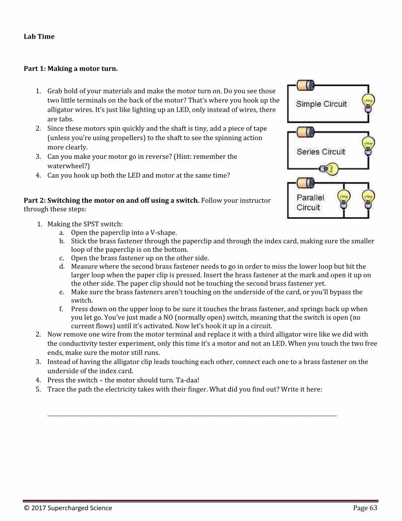
© 2017 Supercharged Science Page 63
Lab Time
Part 1: Making a motor turn.
1. Grab hold of your materials and make the motor turn on. Do you see those
two little terminals on the back of the motor? That’s where you hook up the
alligator wires. It’s just like lighting up an LED, only instead of wires, there
are tabs.
2. Since these motors spin quickly and the shaft is tiny, add a piece of tape
(unless you’re using propellers) to the shaft to see the spinning action
more clearly.
3. Can you make your motor go in reverse? (Hint: remember the
waterwheel?)
4. Can you hook up both the LED and motor at the same time?
Part 2: Switching the motor on and off using a switch. Follow your instructor through these steps:
1. Making the SPST switch: a. Open the paperclip into a V-shape. b. Stick the brass fastener through the paperclip and through the index card, making sure the smaller
loop of the paperclip is on the bottom. c. Open the brass fastener up on the other side. d. Measure where the second brass fastener needs to go in order to miss the lower loop but hit the
larger loop when the paper clip is pressed. Insert the brass fastener at the mark and open it up on the other side. The paper clip should not be touching the second brass fastener yet.
e. Make sure the brass fasteners aren’t touching on the underside of the card, or you’ll bypass the switch.
f. Press down on the upper loop to be sure it touches the brass fastener, and springs back up when you let go. You’ve just made a NO (normally open) switch, meaning that the switch is open (no current flows) until it’s activated. Now let’s hook it up in a circuit.
2. Now remove one wire from the motor terminal and replace it with a third alligator wire like we did with
the conductivity tester experiment, only this time it’s a motor and not an LED. When you touch the two free
ends, make sure the motor still runs.
3. Instead of having the alligator clip leads touching each other, connect each one to a brass fastener on the
underside of the index card.
4. Press the switch – the motor should turn. Ta-daa!
5. Trace the path the electricity takes with their finger. What did you find out? Write it here:
____________________________________________________________________________________________________________
© 2017 Supercharged Science Page 64
____________________________________________________________________________________________________________
____________________________________________________________________________________________________________
Part 3: Making the motor go forward and reverse using a single switch. Follow your instructor’s directions:
1.Making the DPDT switch:
a. We’re going to put six brass fasteners on the card, three in each row. Insert the two middle brass
fasteners first, each with their own paperclip attached. Open them up on the other side and tape
them down on the underside so they are out of reach of other fasteners but can still be attached
to alligator clip leads.
b. Move both the paperclips up and mark the next location for the fasteners. Insert two fasteners, one on each side, and open them up on the underside of the card. Tape into place.
c. Move the paperclips down and mark the last set of points for the last two fasteners. Insert fasteners, open up, and tape.
d. Show the kids how to operate the switch and have them practice before wiring it up. Both paperclips up means forward, both down is reverse. No contact is off.
e. Working on the underside of the card: use two alligator clips to make the “X." Connect one
alligator clip to a corner (it doesn’t matter which) and the other end connects to the fastener in
the opposite diagonal corner. If you grab the stems that are peeking out of the tape, it’s easier to
connect to. Do this for both diagonals.
f. Connect one alligator clip wire to the negative wire on the battery back and then to one of the middle brass fasteners.
g. Connect one alligator clip wire to the positive wire on the battery back and then to the other middle brass fastener.
h. Connect one alligator wire to each motor terminal (you should have two wires connected to
your motor). Connect the other ends of the wires to two brass fasteners on one end of the
switch (it doesn’t matter which), but they must be on the same end.
i. Test your motor and see how it works! If it doesn’t work, remove all the wires and redo steps f-h. If you still have trouble, grab a new set of wires and see if this helps.
2. Trace the path the electricity takes with your finger. What did you find out? Write it here:
____________________________________________________________________________________________________________
© 2017 Supercharged Science Page 65
____________________________________________________________________________________________________________
____________________________________________________________________________________________________________
Reading
Do you remember how the yardstick moved around in a circle using a balloon way back in Lesson #6: The
Electrostatic Motor? Using static charge attraction, the yardstick followed the balloon around in a circle.
Imagine modifying the experiment so that there was a charged balloon physically attached to the end of the
yardstick, so that you could use a positively charged object to attract and pull the yardstick toward you, and then
just as the stick was close, you quickly switched to a negatively charged object to push the object away. That’s how
the electrostatic bottle motor worked in a previous experiment.
Now place those statically charged objects with magnets. You’ve got a magnet on something which can move in a
circle, and another magnet you can flip North-South depending on where the rotating magnet is. That’s how a
motor works! We’re going to actually build a motor using these principles when we get to electromagnetism, and
we have to wait a bit before making one because we’re going to make a magnet that we can turn on and off for that
project, and there’s a few more things we need to learn how to do first.
Remember the water analogy? Suppose you add in a valve so you can turn the water on and off through your pipe.
What is the valve like in your circuit? It’s just like a switch in a circuit, because it interrupts the flow of electricity.
There are different kinds of switches, but they all do the same thing: allow you to control when electricity flows
through the circuit.
Think of this switch like a train track. When you throw the switches one way, the train (electrons) can race
around the track at top speed. When you turn the switch to the OFF position, it’s like a bridge collapse for the train
– there’s no way for the electrons to jump across from the brass fastener to the paper clip. When you switch it to
the ON position (both sides), you’ve rebuilt the bridges for the train (electrons).
Exercises
1. If you want to reverse the spin direction of a motor without using a switch, what can you do?
© 2017 Supercharged Science Page 66
2. A simple switch can be made out of what kinds of materials?
3. How would you make your SPST switch an NC (normally closed) switch?
4. How did you have to connect your circuit in order for both the LED and motor to work at the same time? Draw it here:
5. Draw a picture of your experiment that explains how the SPST switch works, and show how electricity flows through your circuit:
© 2017 Supercharged Science Page 67
Extra Credit (for students who have completed Part 3):
6. Draw a picture of your experiment that explains how the DPDT switch works in your circuit and show how to wire up the circuit.
Answers to Exercises: Switches & Motors
1. If you want to reverse the spin direction of a motor without using a switch, what can you do? (Switch the wires on the back of the motor.)
2. A simple switch can be made out of what kinds of materials? (You need to be able to control when it
conducts and insulates. Take the two wires (one from the battery and the other from the motor)
and touch them together – ON – OFF – ON – OFF. Simplest switch in the world! Air is the insulator
and metal is the conductor. But you can also use index cards, paper clips, and brass fasteners.)
3. How would you make your SPST switch an NC (normally closed) switch? (Leave the paperclip in
its normal shape (don’t bend into a V) and touch the paperclip to the brass fastener. The motor
will run until you move the paperclip away.)
4. How did you have to connect your circuit in order for both the LED and motor to work at the same time? (If they wire it up in series (plus to minus), they’ll find it doesn’t work. If they hook it up in parallel (plus to plus), then both will work with one battery pack.)
5. Draw a picture of your experiment that explains how the SPST switch works, and show how electricity flows through your circuit.
Extra Credit (for students who have completed Part 3):
6. Draw a picture of your experiment that explains how the DPDT switch works in your circuit and show how to wire up the circuit.
© 2017 Supercharged Science Page 69
LOADS IN A CIRCUIT
I mentioned earlier how the LED was called a load in an electric circuit. The truth is, a load can be anything like a doorbell in an alarm, a motor in a robot, a garbage disposal, a garage door opener… you get the idea. A load is the device that transforms the energy from the battery into useful and non-useful energy. Non-useful is like the heat coming off an incandescent light bulb, whereas the useful energy is the light itself. Rarely are light bulbs used for heat, so we’d call that heat energy non-useful energy.
© 2017 Supercharged Science Page 70
POWER
We’re going to define power in an electric circuit as the rate tat electrical energy is used by the load (or supplied by the source). Power is then equal to the work done by the charge per unit time, or said another way, the rate that the charge changes its energy (whether it’s lost or gained). For a battery, the charge gains energy so it’s a positive quantity, and in the devices in the circuit (the load), energy is lost, so the change is negative. Power is measured in Watts (W), and 1 watt delivers 1 joule of energy every second.
1 Watt = 1 Joule / second
An incandescent light bulb might have a 100 Watt rating stamped on it, which means 100 joules of energy is being delivered every second to the light bulb. A 15 watt night light gets 15 joules of energy every second.
Have you ever seen an electric bill? They don’t charge you by the “watt”, but by the “kWhr” or “kWh”, which is a kilowatt-hour. (A kilowatt is 1,000 watts.) A kWhr is a unit of power per unit time, which means it’s a measure of energy. Your electric bill is a bill for energy, not power.
© 2017 Supercharged Science Page 71
MAKING SENSE OF IT ALL
A lot of people don’t understand electricity, but they use it all the time. Normally I’d agree with this approach: know enough so you can make good use of it, and for the most part, I’ve done that in this course. However, because this is such an advanced course specifically in electricity, I want to make sure we’ve busted the main myths out there around electricity, Over the years, I’ve heard many different ideas folks have about electricity, and at some level, it’s really not their fault for these misconceptions because they are still so popular.
It’s important as a scientist that you question not only what you know but how you know what you know. This will lead you to the truth about how things work, and not just what most people think the reason is (which isn’t usually correct). Here are a couple of mainstream ones that still persist today:
1. If a battery is dead, it is out of charge, and you have to recharge it so it works. 2. The current that flows through the circuit starts in the battery. 3. The utility company supplies electrons to your house through the outlet. 4. Electrons move at light speed in the circuit. 5. Electrons get used up as they move through the circuit. 6. Benjamin Franklin invented the light bulb.
Note that all of these above are false! Your test for today is to make sure you understand why that is for each one. Go back and re-read this section and the previous sections if you need more help. Here’s a couple of hints if you need it: To review, a battery provides energy move a charge from a low potential to a high potential, and the charge came from the wires and electrical components inside the circuit itself. The charge is carried by electrons in the metal components. Charge moves really slow (about 1 meter per hour), but the signal to moves travels near the speed of light. Charge moves through the circuit at the same rate everywhere in the circuit (charge doesn’t build up in a circuit that is closed and conducting properly). A circuit is really an energy transforming device that takes chemical energy from the battery and transformed it to electrical energy in the circuit and transforms that into different kinds of energy like motion, heat, light, and sound.
© 2017 Supercharged Science Page 72
ELECTRICAL RESISTANCE
As electrons move through a load in an electric circuit (devices like a LED, buzzer, motor, etc.), they experience resistance (even through the wire itself), which corresponds to a drop in energy . This drop in energy is referred to as a voltage drop. Resistance hinders the flow of electrons, even in the water itself. You can think of resistance as the friction between the water and the pipe along the inside of the pipe.
The pipe, just like the wire, has a certain diameter and length. The longer the wire, the more resistance the electron will encounter, just as with a long pipe of water. If you increase the pipe diameter, more water will flow through it. The thicker the wire, the more current flows through it. The amount of resistance the charge encounters also depends on what the wire is made out of. Certain materials are more electrically conductive than others, with silver, copper and gold being at the very low end of electrical resistance (which is why most wires are made from copper, which is the least expensive of the three).
It’s easy to find the resistance of objects using a simple mathematical equation that relates the length of the wire, the cross-sectional area, and the resistivity of the material. Here’s an example of how to do it:
© 2017 Supercharged Science Page 73
RESISTANCE OVER DISTANCES
Let’s see how a length of wire changes its resistance depending on how long it is:
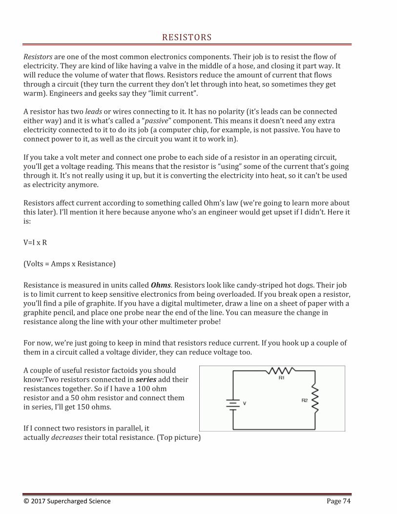
© 2017 Supercharged Science Page 74
RESISTORS
Resistors are one of the most common electronics components. Their job is to resist the flow of electricity. They are kind of like having a valve in the middle of a hose, and closing it part way. It will reduce the volume of water that flows. Resistors reduce the amount of current that flows through a circuit (they turn the current they don’t let through into heat, so sometimes they get warm). Engineers and geeks say they “limit current”. A resistor has two leads or wires connecting to it. It has no polarity (it’s leads can be connected either way) and it is what’s called a “passive” component. This means it doesn’t need any extra electricity connected to it to do its job (a computer chip, for example, is not passive. You have to connect power to it, as well as the circuit you want it to work in). If you take a volt meter and connect one probe to each side of a resistor in an operating circuit, you’ll get a voltage reading. This means that the resistor is “using” some of the current that’s going through it. It’s not really using it up, but it is converting the electricity into heat, so it can’t be used as electricity anymore. Resistors affect current according to something called Ohm’s law (we’re going to learn more about this later). I’ll mention it here because anyone who’s an engineer would get upset if I didn’t. Here it is:
V=I x R
(Volts = Amps x Resistance)
Resistance is measured in units called Ohms. Resistors look like candy-striped hot dogs. Their job is to limit current to keep sensitive electronics from being overloaded. If you break open a resistor, you’ll find a pile of graphite. If you have a digital multimeter, draw a line on a sheet of paper with a graphite pencil, and place one probe near the end of the line. You can measure the change in resistance along the line with your other multimeter probe!
For now, we’re just going to keep in mind that resistors reduce current. If you hook up a couple of them in a circuit called a voltage divider, they can reduce voltage too. A couple of useful resistor factoids you should know:Two resistors connected in series add their resistances together. So if I have a 100 ohm resistor and a 50 ohm resistor and connect them in series, I’ll get 150 ohms. If I connect two resistors in parallel, it actually decreases their total resistance. (Top picture)
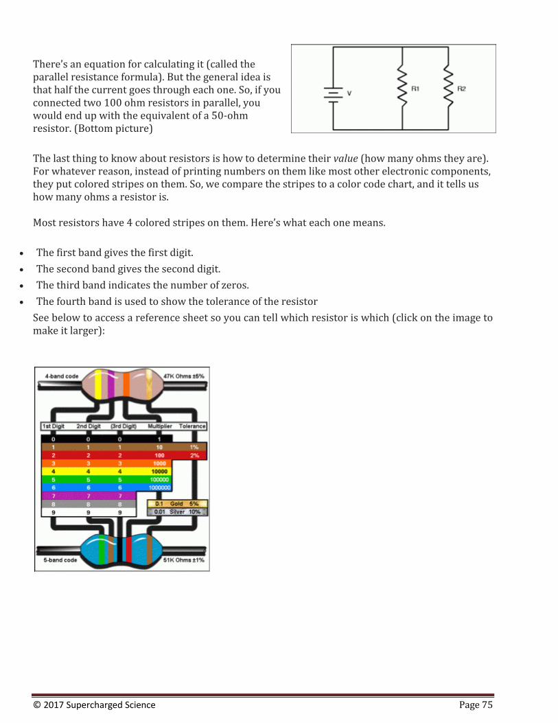
© 2017 Supercharged Science Page 75
There’s an equation for calculating it (called the parallel resistance formula). But the general idea is that half the current goes through each one. So, if you connected two 100 ohm resistors in parallel, you would end up with the equivalent of a 50-ohm resistor. (Bottom picture) The last thing to know about resistors is how to determine their value (how many ohms they are). For whatever reason, instead of printing numbers on them like most other electronic components, they put colored stripes on them. So, we compare the stripes to a color code chart, and it tells us how many ohms a resistor is. Most resistors have 4 colored stripes on them. Here’s what each one means.
The first band gives the first digit.
The second band gives the second digit.
The third band indicates the number of zeros.
The fourth band is used to show the tolerance of the resistor
See below to access a reference sheet so you can tell which resistor is which (click on the image to make it larger):
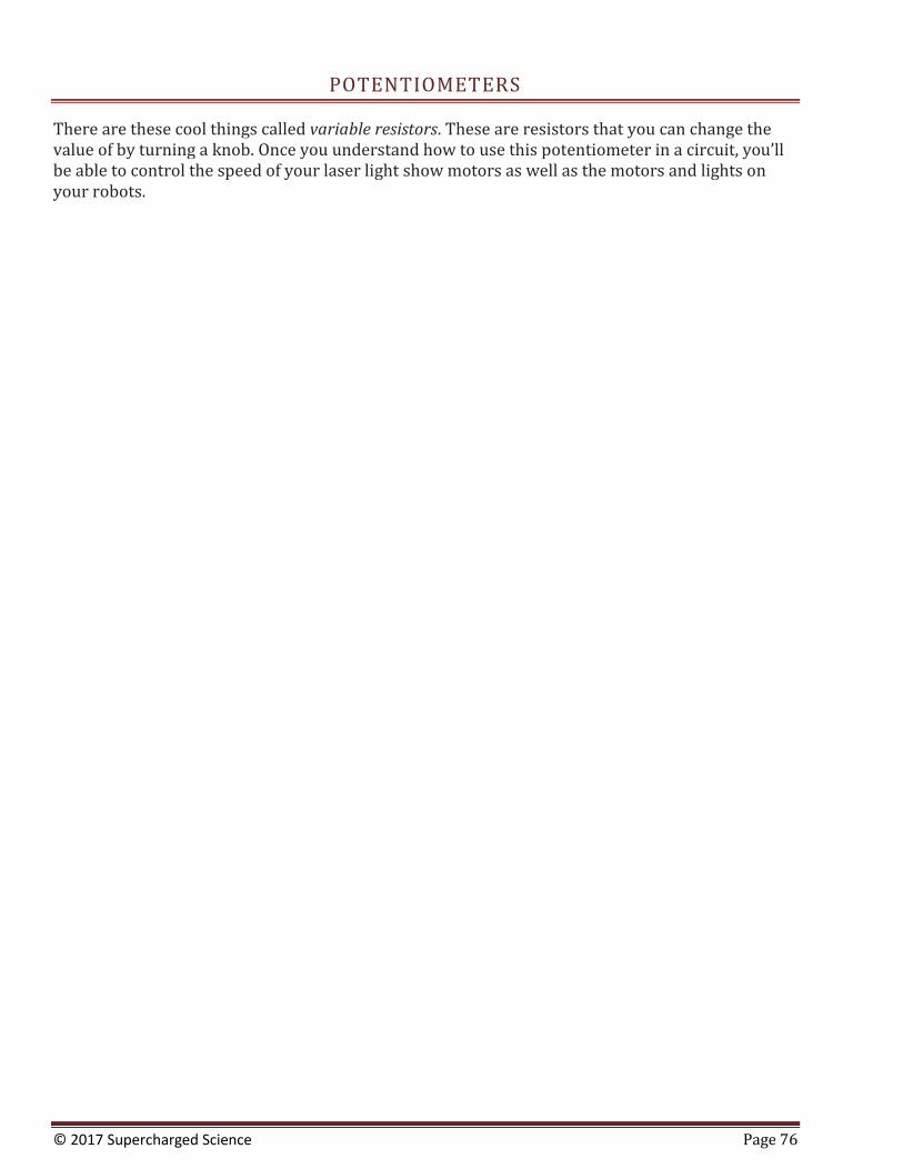
© 2017 Supercharged Science Page 76
POTENTIOMETERS
There are these cool things called variable resistors. These are resistors that you can change the value of by turning a knob. Once you understand how to use this potentiometer in a circuit, you’ll be able to control the speed of your laser light show motors as well as the motors and lights on your robots.
© 2017 Supercharged Science Page 77
MEASURING VOLTAGE AND CURRENT
One of the most useful tools a scientist can have is a digital multimeter (DMM)! A digital multimeter can quickly help you discover where the trouble is in your electrical circuits and eliminate the hassle of guesswork. When you have the right tool for the job, it makes your work a lot easier (think of trying to hammer nails with your shoe). I’ll show you how to get the most out of this versatile tool that we’re sure you’re going to use all the way through college.

© 2017 Supercharged Science Page 78
OHM’S LAW
One of the most important equations in current electricity is: V = IR. With one glance, you can see
how current, voltage, and resistance are related to each other. If the current decreases, so does the
voltage. Charge mores when the resistance decreases.

© 2017 Supercharged Science Page 79
APPLYING OHM’S LAW
Now let’s take a look at a couple of sample calculations so you really understand how to do this…
© 2017 Supercharged Science Page 80
POWER AND OHM’S LAW
There are two main equations for power in the field of current electricity: P = I2 R P = V2/R where P = power (watts), V = voltage (volts), R = resistance (ohms), I = current (amps) Using these three equations (the two above and V = IR) will solve most of your problems in physics having to do with current electricity. However, there are a few things to keep in mind before you dive in too deeply…

© 2017 Supercharged Science Page 81
HAIR DRYER PROBLEM
I do have a LOT of hair on my head. Here’s a neat way to figure out how much current I use every morning I fire up the hair dryer:
© 2017 Supercharged Science Page 82
TOASTER PROBLEM
Do you like toast? Here’s how much current it takes to transform ordinary bread into crunchy toast:
© 2017 Supercharged Science Page 83
BULB WATTAGE
What’s the difference between a 60W at a 120W bulb? Let’s take a look…
© 2017 Supercharged Science Page 84
CIRCUIT CONNECTIONS
It’s easy to see how the current flows through a circuit that has only one component, like one LED connected to the battery. If it’s a 3 Volt battery, then there’s 3 Volts across the LED also.
But what if there are two or three LEDs? How does the voltage look across each one? What if the LEDs are different sizes? Does it matter how you hook them up, meaning does one way make the LED last monger or glow brighter? Let’s take a look at the difference between series and parallel connections. You can have resistors in series, batteries in parallel, motors in series and parallel, and hundreds more different combinations! It all depends on what you want to do and how you want to do it.
For example, a 6V lantern battery is actually made up of four D-cell batteries connected in series. Each D-cell is 1.5V, and when you add four of them up, you get 6V. The older models of these used to have 24 AA batteries which were connected in series and parallel to make 6V. We’re going to learn how to decide whether to use a series or parallel circuit, depending on what we’re building and what we need the circuit to do. Which bring up another point… what’s the difference between a D-cell and a AAA battery? They both are 1.5 volts. Why use one over the other? And 9V batteries are smaller and lighter than a D-cell but have 6 times the voltage… why wouldn’t yo use 9V for everything?
It has to do with current (the rate of charge flowing through the circuit). A D-cell has much more current than a AAA battery, and you’d use D-cells for things like motors. AAA are perfect for LEDs and other low-current devices that don’t need as much amps to get them going. In your circuit, you want to choose the best option that will still work voltage and amperage-wise, is the least expensive, and lasts long enough so you’re not changing batteries every few minutes.
© 2017 Supercharged Science Page 85
SERIES CIRCUITS
Each electrical component is connected so that there’s only one option for the current to flow. There’s no branches or alternate routes for the electricity… it’s only got one way to move through the circuit. When you add more electrical components, like motors or LEDs to this circuit, the overall resistance in the circuit decreases since there’s only one path for the current. Let’s look at how charge flows through a series circuit:
© 2017 Supercharged Science Page 86
PARALLEL CIRCUITS
Each device, like a motor or LED, has its own branch lines in a parallel circuit, which means that the electricity has many different ways that it can travel along the circuit lines. When scientists and engineers draw electrical diagrams, they put one electric component on each branch, even if in reality there’s more than one when you actually build the thing. Unlike series circuits, when you add another branch, you also allow more pathways for the electricity to follow.
© 2017 Supercharged Science Page 87
CALCULATING AND MEASURING CURRENT
Current and charge aren’t quite the same thing. Current is rate that charge goes through a circuit (just like acceleration is the rate of change in velocity… acceleration and velocity aren’t the same thing either, but they are related). Remember, charge doesn’t get used up by electrical components like LEDs or resistors.
© 2017 Supercharged Science Page 88
OHM’S LAW AND CURRENT
One more thing to note about the difference between series and parallel circuits is that in a parallel circuit, the current in each branch can be different, but they all add up to be the same everywhere once you reduce the branches into a single branch. Just like the water analogy, when you connect the main hose into five different smaller hoses, the sum of all five is going to equal flow through the main hose.
© 2017 Supercharged Science Page 89
OHM’S LAW AND POWER
Now let’s take a look at how Ohm’s Law and Power work together:

© 2017 Supercharged Science Page 90
APPLYING OHM’S LAW
Physics equations are pretty useless unless you really understand how to apply them… that’s when the real magic happens. Here’s an example of how to apply Ohm’s law intelligently and easily.
© 2017 Supercharged Science Page 91
SERIES AND PARALLEL REVIEW
We’re about to jump into making a lot of really cool experiments with different electrical components, but before we do, let’s recap what we’ve covered so you’re sure not to miss any important concepts.
© 2017 Supercharged Science Page 92
SERIES AND PARALLEL CIRCUITS IN EVERYDAY LIFE
It’s easy to get sucked into doing math and equations all day without understanding how it applies to the real world. Let’s take a look at how to actually hook up series and parallel circuits in everyday life, and how they are different, and when to use each one…

© 2017 Supercharged Science Page 93
BREADBOARDS
It’s easy to get lost in the details, especially when the content is more on the abstract side (like it is with electricity). That’s why I am going to give you a really neat set of hands-on projects that you can build with a very small supply of materials that you can use for all five projects. Ready to actually use this stuff? Here’s how to use a what scientists call a breadboard to hold your circuits together when it’s too complicated to do with just wires:

© 2017 Supercharged Science Page 94
SERIES SWITCHES
If you have the Electronics Learning Lab from Unit 14, here’s how you do it with the breadboard. (If you don’t have it, that’s okay also… just see how well you can follow along, because the concepts are the same even if your lab equipment looks different. The first video shows you step by step how to wire up switches in series (which is common to do in electronics):
© 2017 Supercharged Science Page 95
PARALLEL SWITCHES
Again, if you happen to have the Electronics Learning Lab from Unit 14, pull it out and follow along. If you don’t have it, that’s okay also… just see how well you can follow along, because the concepts are the same even if your lab equipment looks different. The first video shows you step by step how to wire up switches in series (which is common to do in electronics): This video is how to connect the switches in parallel:
© 2017 Supercharged Science Page 96
LIGHT ACTUATED CIRCUIT
In this circuit, we’re going to use a special kind of resistor, called a CdS photocell to detect light and dark. When light is shined on the photocell, the LED will light up. When it is dark, the LED goes out. And with just a little light, the LED is dim.
© 2017 Supercharged Science Page 97
LIGHT DE-ACTUATED CIRCUIT
In this circuit, the LED is actuated only when the photoresistor is dark. Photoresistors (also called CdS photocells) are made of a material that reacts with light, very similar to solar cells. When light hits the material, it knocks a few electrons loose. When you hook up the cell to a circuit, the electrons now have a place to go, and electricity flows through your wires. You’ll notice your CdS cell works when you shine a light on it from either the front side or the back side. If you want to use a phototransistor, make a note as to the frequency of light it’s been tuned to – some will only work with IR light (like your remote control or sunlight).
© 2017 Supercharged Science Page 98
HOW TO READ SCHEMATICS
Do you remember the first time you tried to read a map? There were all those weird symbols and curving lines that you had to figure out before you could get anywhere. Electric circuits are kind of the same way… people use schematic diagrams to write down how their circuit is wired so others can build it, too. Now that you’ve built a couple of the breadboard circuits, it’s time to figure out how to read the symbols and build a circuit from a diagram. At first, it may seem a bit overwhelming with all the strange symbols and lines drawn all over the page, but don’t worry – after a couple of circuits, you’ll be cruising through these like a pro.
© 2017 Supercharged Science Page 99
TRANSISTOR CIRCUITS
This Flashing Circuit used to be a real ‘wowser!’ with students before LEDs become commonplace (around 1995). You’re going to build a circuit that has a control knob that will allow you to set the flash speed of the LED. You can try different LEDs or mini-lamps to see what kind of an effect you get. NPN and PNP transistors are similar in that when current is applied to the base, electricity flows through them. But, the way they are used is different. NPN transistors are often used to control whether a circuit is completed by connecting it to ground or not, where PNP control the positive current going into a device (or portion of a circuit). NPN transistors are often used where larger currents need to be controlled, because it’s easier for a transistor to control the ground side of a circuit than the plus power side of it.
© 2017 Supercharged Science Page 100
AUDIBLE LIGHT PROBE
Resistors look like candy-striped hot dogs. Their job is to limit current to keep sensitive electronics from being overloaded. If you break open a resistor, you’ll find a pile of graphite. If you have a digital multimeter, draw a line on a sheet of paper with a graphite pencil, and place one probe near the end of the line. You can measure the change in resistance along the line with your other multimeter probe!
© 2017 Supercharged Science Page 101
LIE DETECTORS
We are going to build an electronic circuit that is able to measure your skin’s resistance. When you sweat (or if your skin is wet), the resistance is different than if it’s dry.
However since most people don’t sweat when they lie, this type of detector isn’t the most reliable type of detector around, but it’s one of the simplest to create. We’re going to build one from simple electronic components like resistors, capacitors, and transistors. Our lie detector uses a speaker that changes pitch depending on the resistance of your skin – it’s much more entertaining than blinking an LED on or off. You can think of this circuit as more of a skin humidity indicator. Can’t get enough of circuits and want to build even MORE? There’s about 100 more step-by-step videos on analog and digital circuits in Unit 14 ready for you to explore. Yay! You’ve completed this set of lessons! Now it’s your turn to do physics problems on your own.
© 2017 Supercharged Science Page 102
HOMEWORK PROBLEMS WITH SOLUTIONS
On the following pages is the homework assignment for this unit. When you’ve completed all the videos
from this unit, turn to the next page for the homework assignment. Do your best to work through as
many problems as you can. When you finish, grade your own assignment so you can see how much
you’ve learned and feel confident and proud of your achievement!
If there are any holes in your understanding, go back and watch the videos again to make sure you’re
comfortable with the content before moving onto the next unit. Don’t worry too much about mistakes at
this point. Just work through the problems again and be totally amazed at how much you’re learning.
If you’re scoring or keeping a grade-type of record for homework assignments, here’s my personal
philosophy on using such a scoring mechanism for a course like this:
It’s more advantageous to assign a “pass” or “incomplete” score to yourself when scoring your
homework assignment instead of a grade or “percent correct” score (like a 85%, or B) simply because
students learn faster and more effectively when they build on their successes instead of focusing on their
failures.
While working through the course, ask a friend or parent to point to three questions you solved correctly
and ask you why or how you solved it.
Any problems you didn’t solve correctly simply mean that you’ll need to go back and work on them
until you feel confident you could handle them when they pop up again in the future.
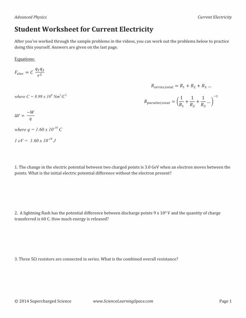
Advanced�Physics� � Current�Electricity��
����������� �������� ��� �� www.ScienceLearningSpace.com� �������
Student�Worksheet�for�Current�Electricity���������������������������������� ����! �����������������"���� �����������������! ����!� �������� �� ������������������ �#�������������������������� �������#�
Equations:
$%&%' ( )� *+*,-,
where C = 8.99 x 10⁹ Nm2/C2�
./ ( � 01*
where q = 1.60 x 10⁻¹⁹ C
1 eV = 1.60 x 10⁻¹⁹ J
23%45%3"6768& ( 2+ 9 2, 9 2: ;
2<848&&%&"6768& ( = �2+
9 �2,
9 �2:
; >?+
�#�@��� �������������� � ��� �������� �!����������� ����������������A#��B�C���������� � �����������!����������������#�D����������������� �� � ��� �������� ��������� �������������� � �����������E�����#���� ���������� ������������������� ��������� ��!���������� ������������F�G���F�C���������H���������� ���������������������I��J#�K���� �������������� �����E�����A#�@�����L���������������� ���� �������������#�D����������� ��!���������� ��������� �E���
�
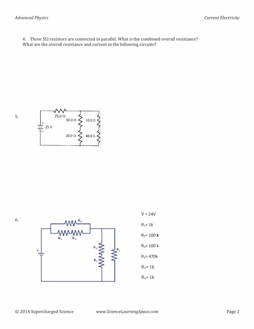
Adva�
�����
��D
������L#�����������I#���������
anced�Physics
������� ��
�# @�����L�D�����������
s�
������� ���
�������������������� ������
��
��� ���� ������� ������
www.Scienc
�������� � #�D������������
ceLearningSp
D����������� ���� ������ �
CR
R
R
R
MM
pace.com
��!��������� ���E��
C�=�24V�R1=�1k�
R2=�100�k�
R3=�100�k�
R4=�470k
MLN���MIN���
��� ���������
Curre
� �E�
ent�Electricity
������
y�
��
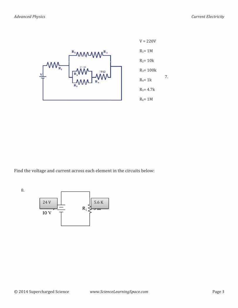
Adva�
�����
�
�
��
������O����
P��
��
anced�Physics
������� ��
�
�������� ����
P#��
�
s�
������� ���
������ ����
���C�
��
���� �������
�
www.Scienc
� ��� �����
L#I�Q
ceLearningSp
��������� ��
pace.com
����!� ��R
C�N����CM�N��SM�N����MAN�����M�N���MLN��#T�MIN��S
��
T#��
C
�
Curreent�Electricity
�����A
y�
A�
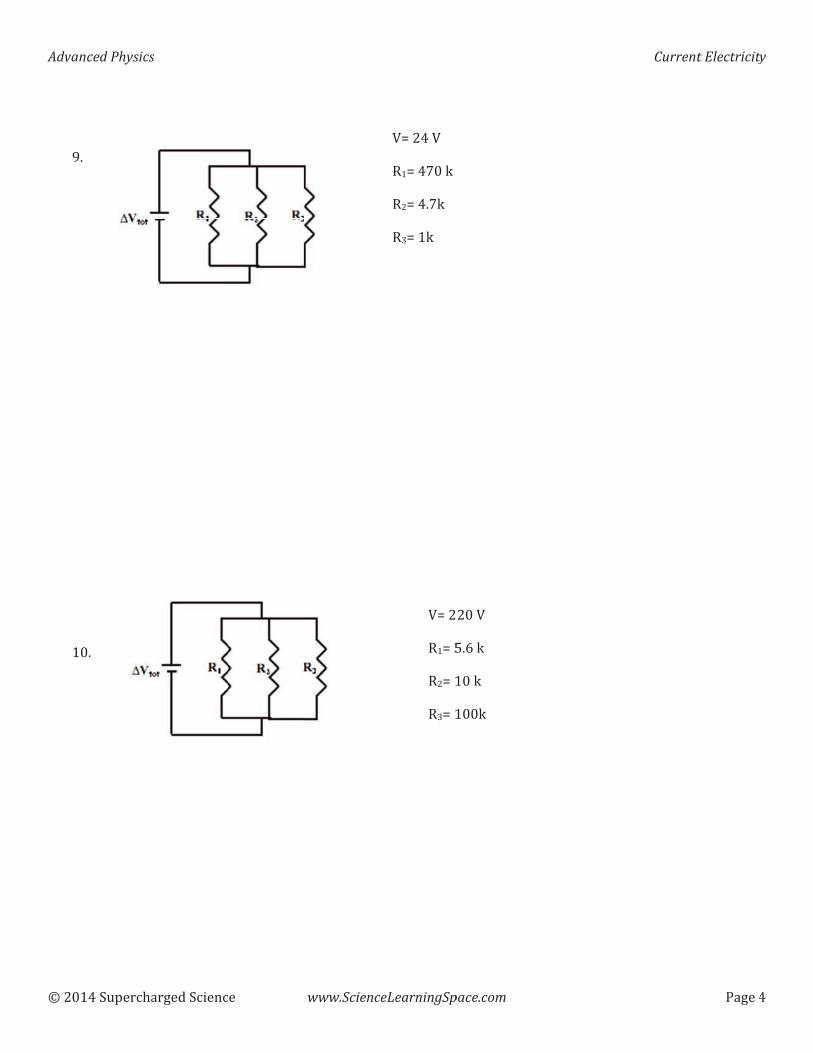
Adva�
�����
��F�����������
������
��
anced�Physics
������� ��
F#��
��#��
s�
������� ��� ��
�
www.SciencceLearningSp
CN����C�M�N��T���M�N��#T�MAN����
CN��M�N�LM�N��MAN��
pace.com
���C�L#I�����������
Curreent�Electricity
������
y�
��
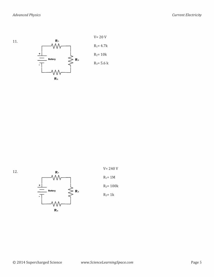
Adva�
�����
��
��#��������������
��
��#������
����
anced�Physics
������� ��
s�
������� ��� �� www.Scienc
CN��M�N�M�N�MAN�
ceLearningSp
���C��#T����L#I���
CN�����C�M�N��SM�N�����MAN����
pace.com
Curreent�Electricity
�����L
y�
L�
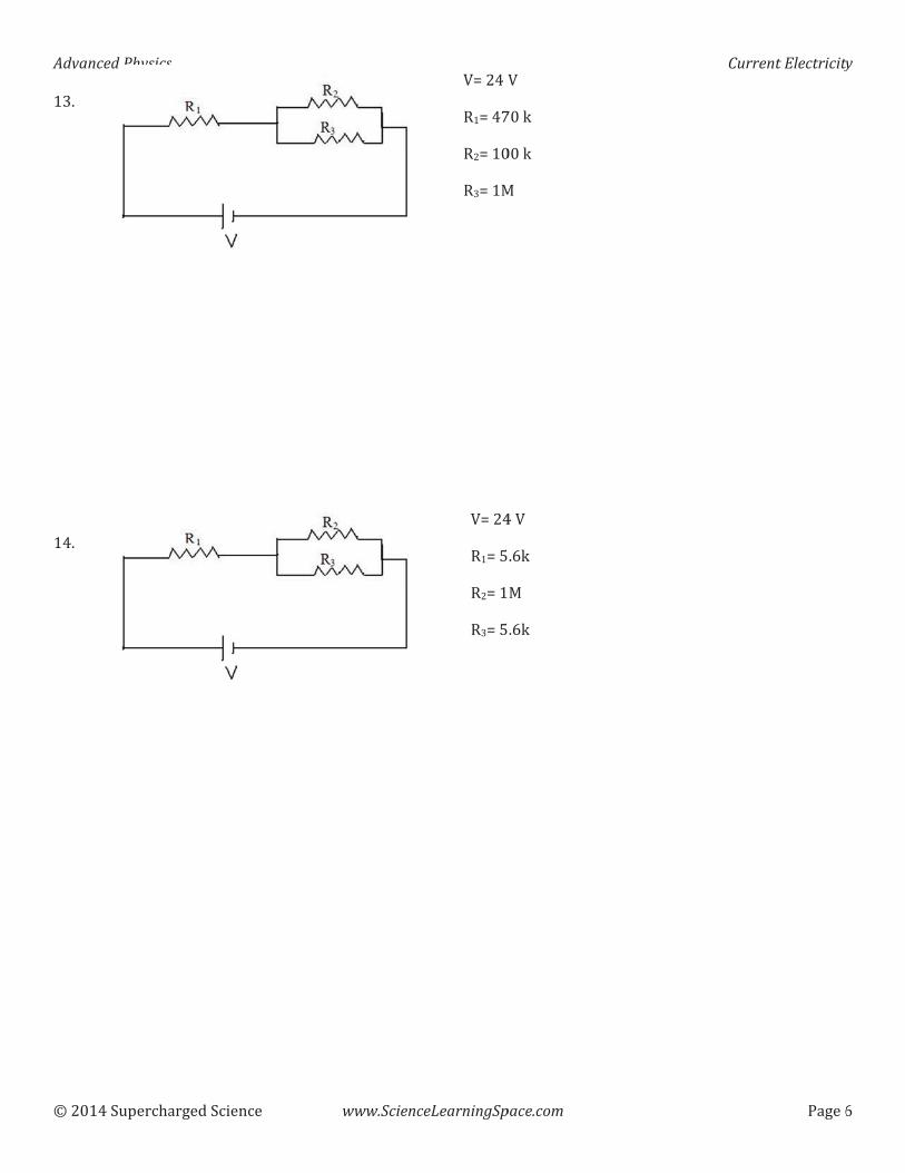
Adva�
�����
�A#���
�������������#����������
anced�Physics
������� ��
s�
������� ��� ��
�
www.SciencceLearningSp
CN����CM�N��TM�N���MAN��S
CN���M�N�LM�N��MAN�L
pace.com
C�T�������S�
��C�#I�S#I��
Curreent�Electricity
�����I
y�
I�
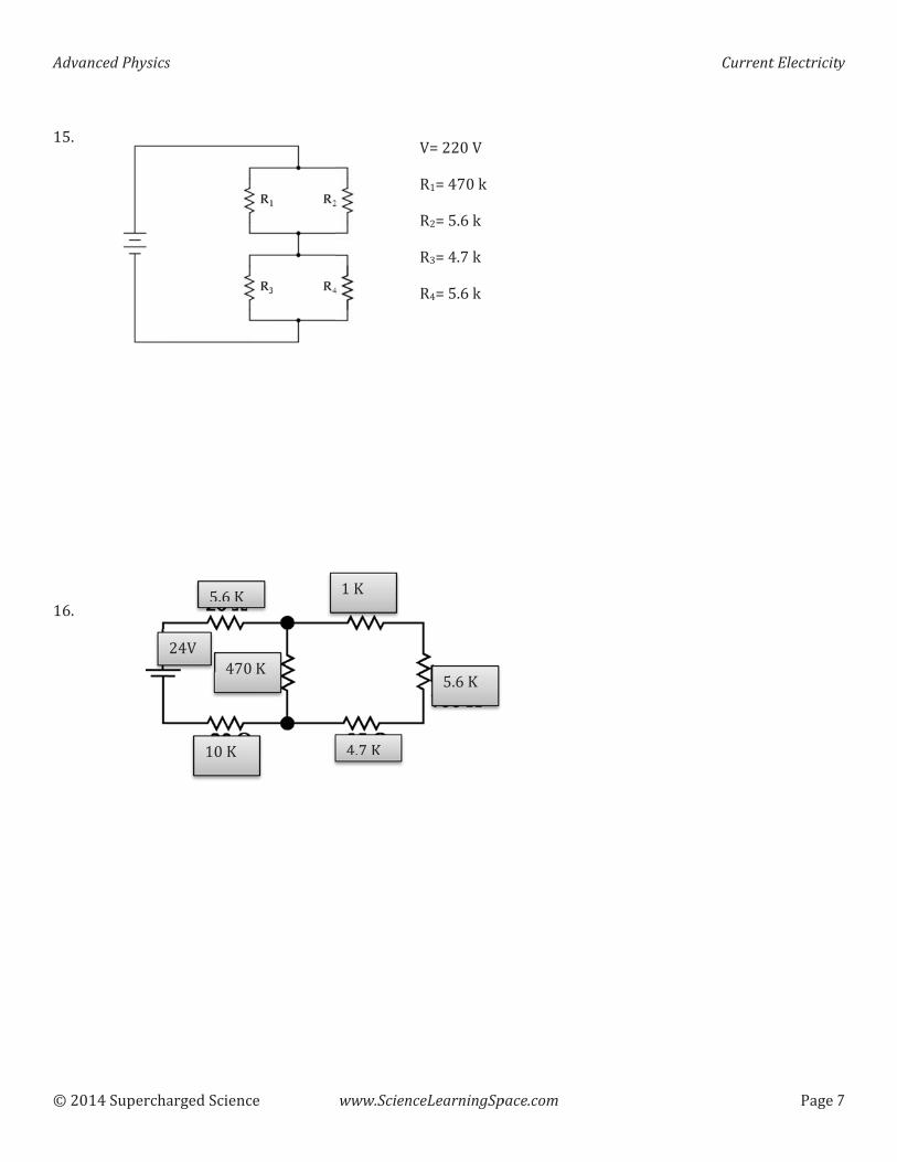
Adva�
�����
��L#���������������I#������
anced�Physics
������� ��
s�
������� ���
L#I Q
���Q�
�T���C�
��
�
�Q�
www.Scienc
��Q
�#T Q
ceLearningSp
CN�����C�M�N��T���M�N�L#I���MAN��#T��M�N�L#I���
L#I�Q
pace.com
�
Curreent�Electricity
�����T
y�
T�
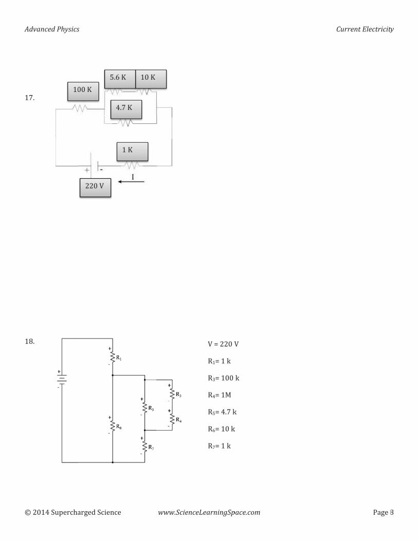
Adva�
�����
����T#�����
�����������P#����������
anced�Physics
������� ��
��
s�
������� ���
����C�
���Q�L#I
�
��
��Q�
���Q�I�Q
�#T�Q�
www.SciencceLearningSp
C�N�����CM�N����MAN�����M�N��SMLN��#T��MIN�����MTN����
pace.com
C
�
��
Curreent�Electricity
�����P
y�
P�
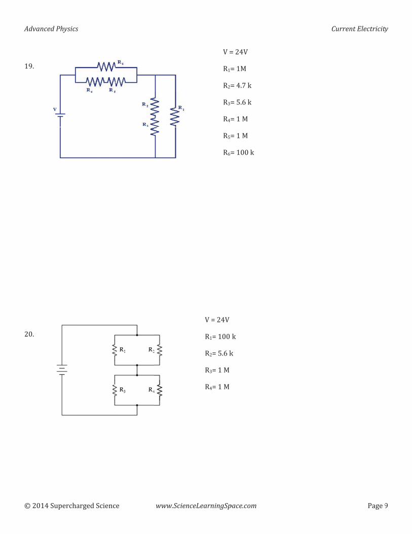
Adva�
�����
���F#�������������������#��
anced�Physics
������� ��
�
s�
������� ��� �� www.SciencceLearningSp
C�NM�NM�NMANM�NMLNMIN
C�N���CM�N�����M�N�L#I��MAN���SM�N���S
pace.com
N���CN��SN��#T��N�L#I��N���SN���SN������
��
Curreent�Electricity
�����F
y�
F�
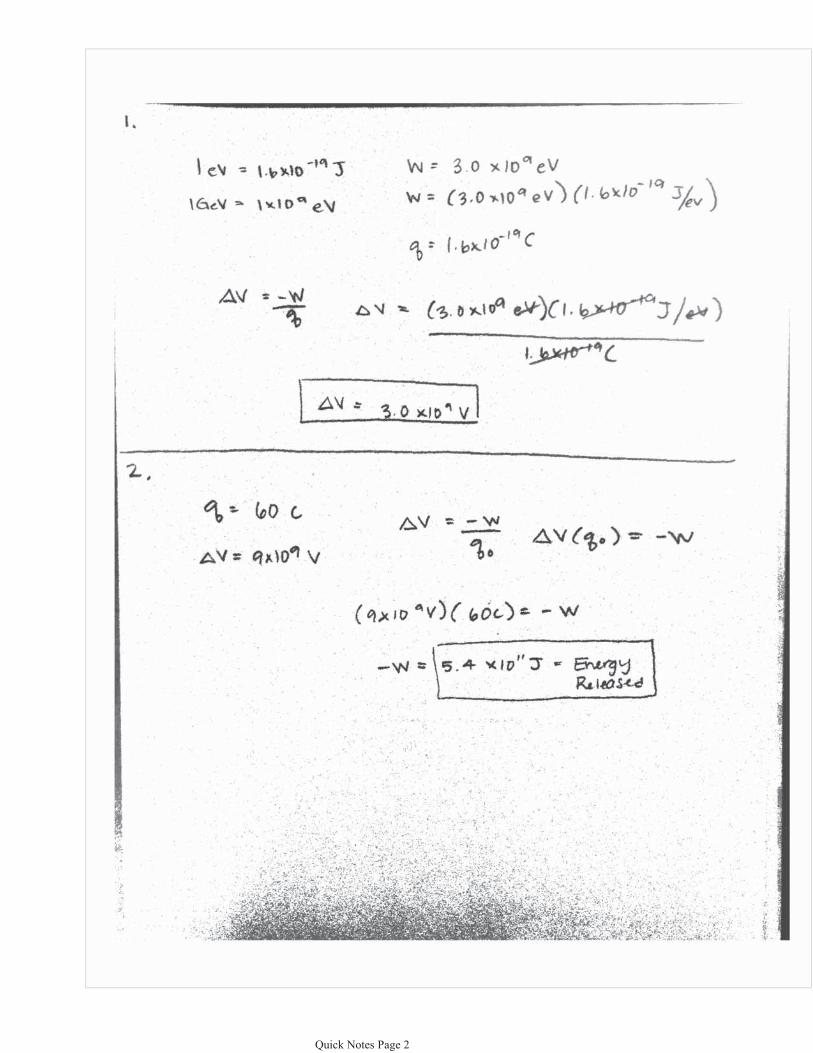
��� ���������� ����� ���
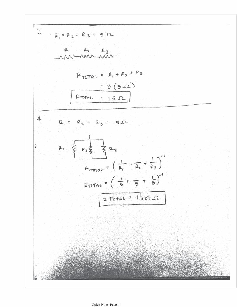
��� ���������� ����� ���
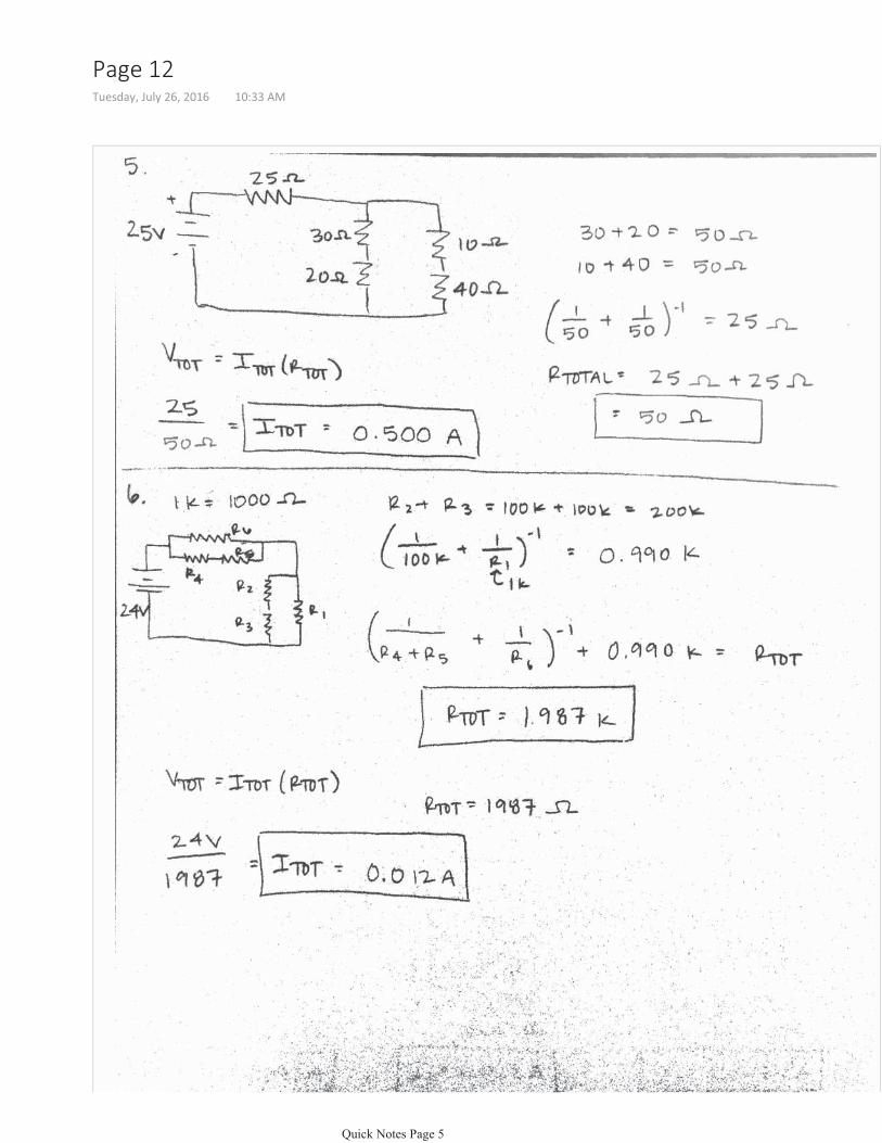
������������������ � ��� �������
��� ���������� ����� ���
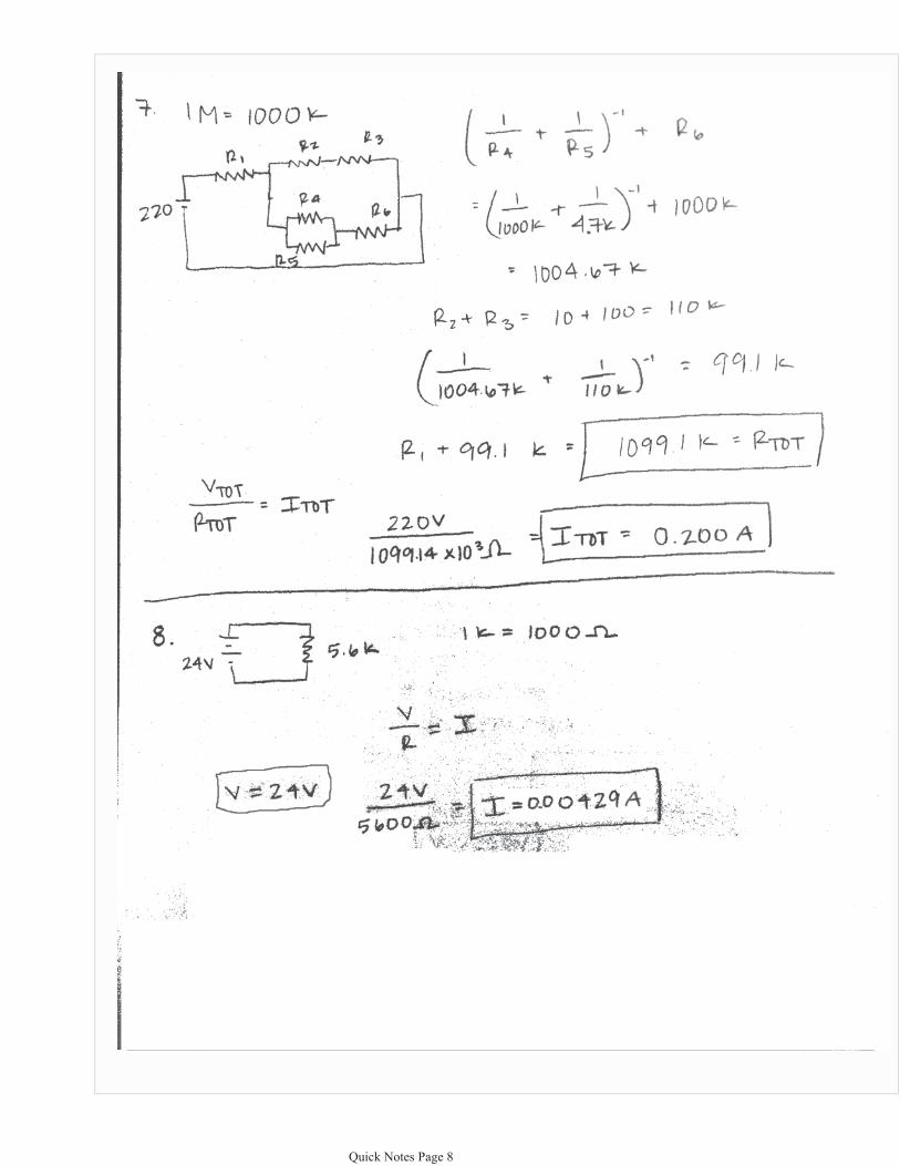
��� ���������� ����� ���
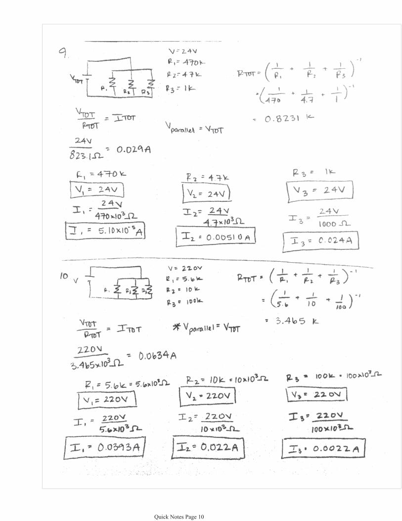
��� ���������� ������ ���
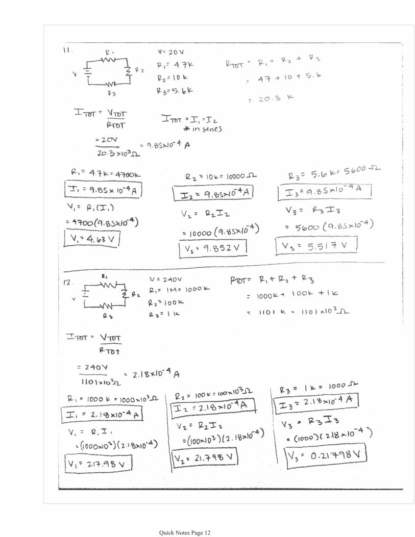
��� ���������� ������ ���
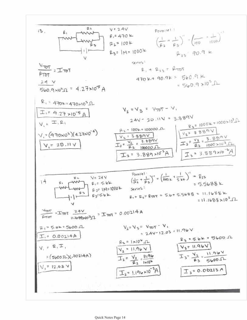
��� ���������� ������ ���
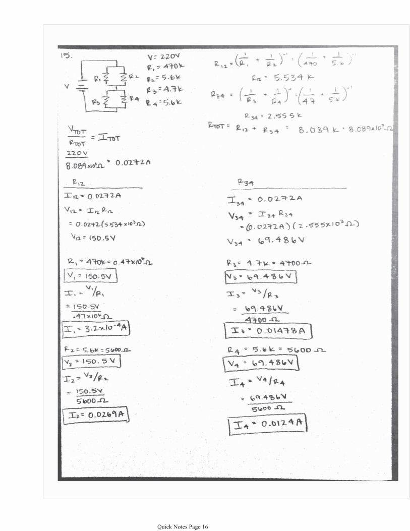
��� ���������� ������ ���
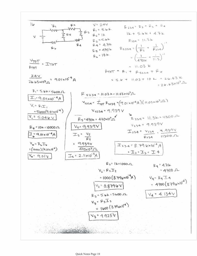
��� ���������� ������ ���
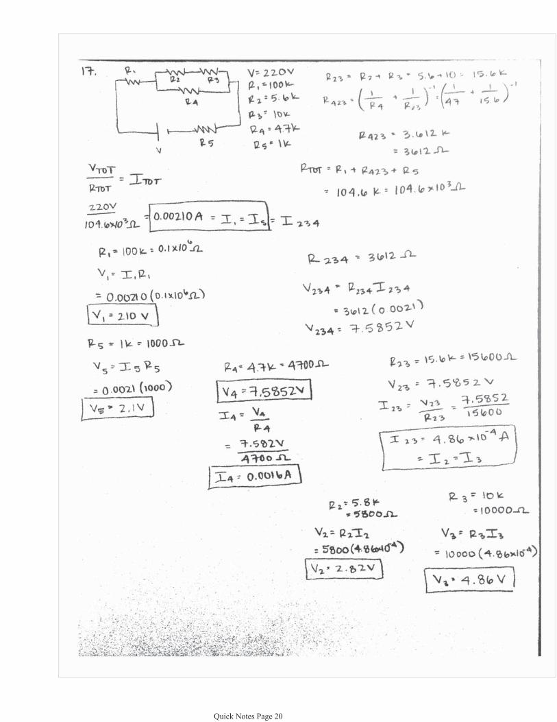
��� ���������� ������ ���
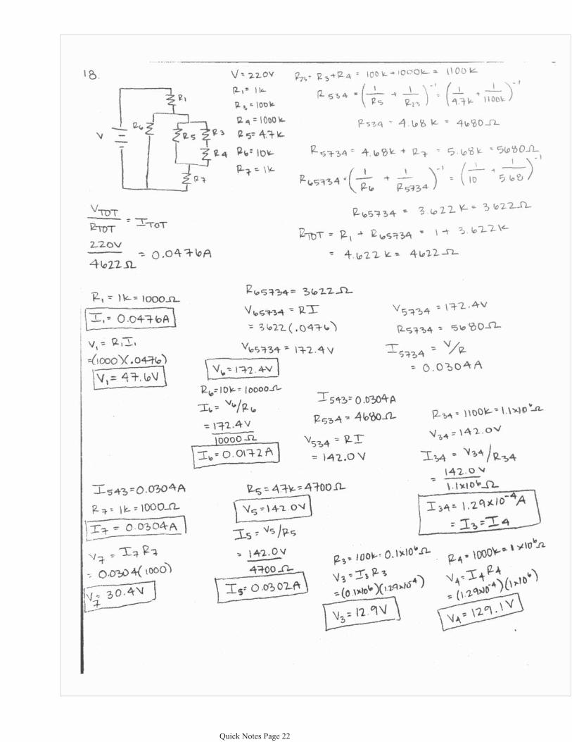
��� ���������� ������ ���
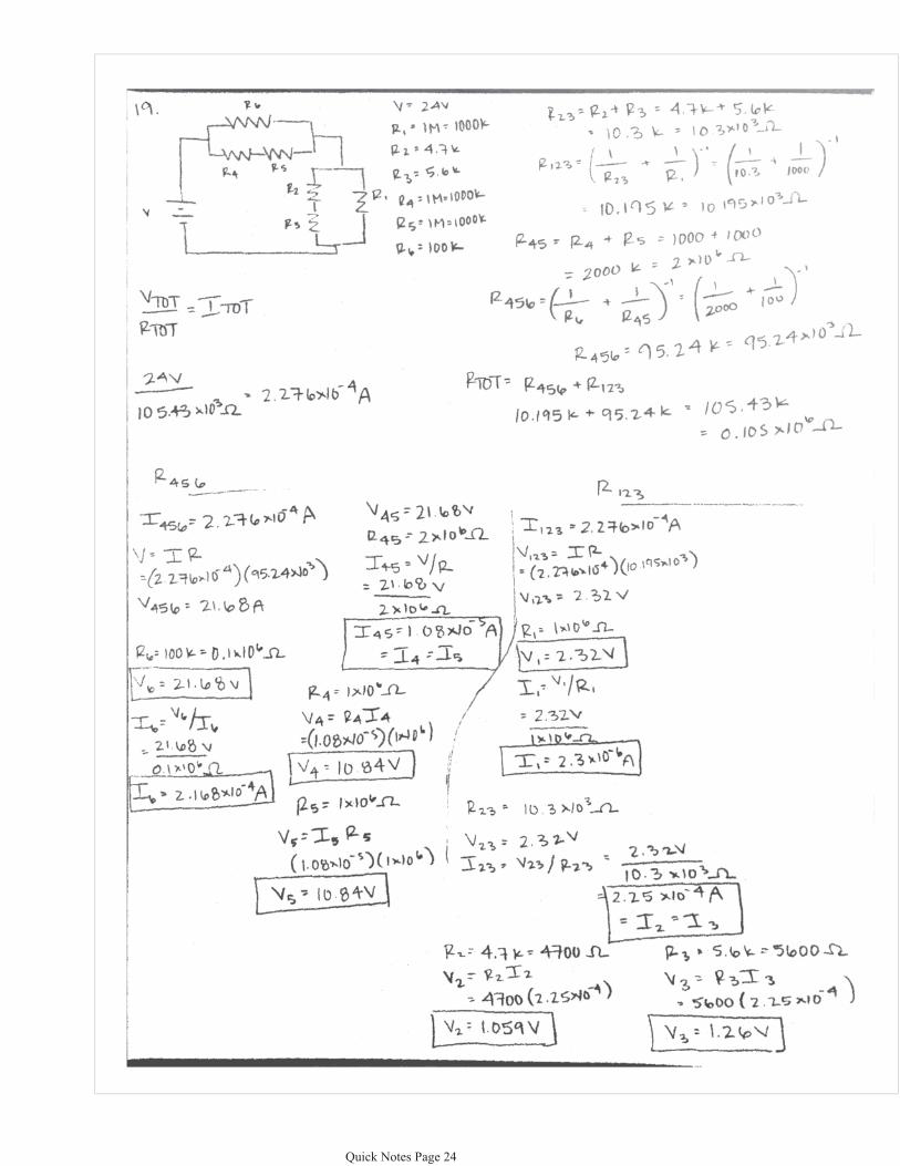
��� ���������� ������ ���
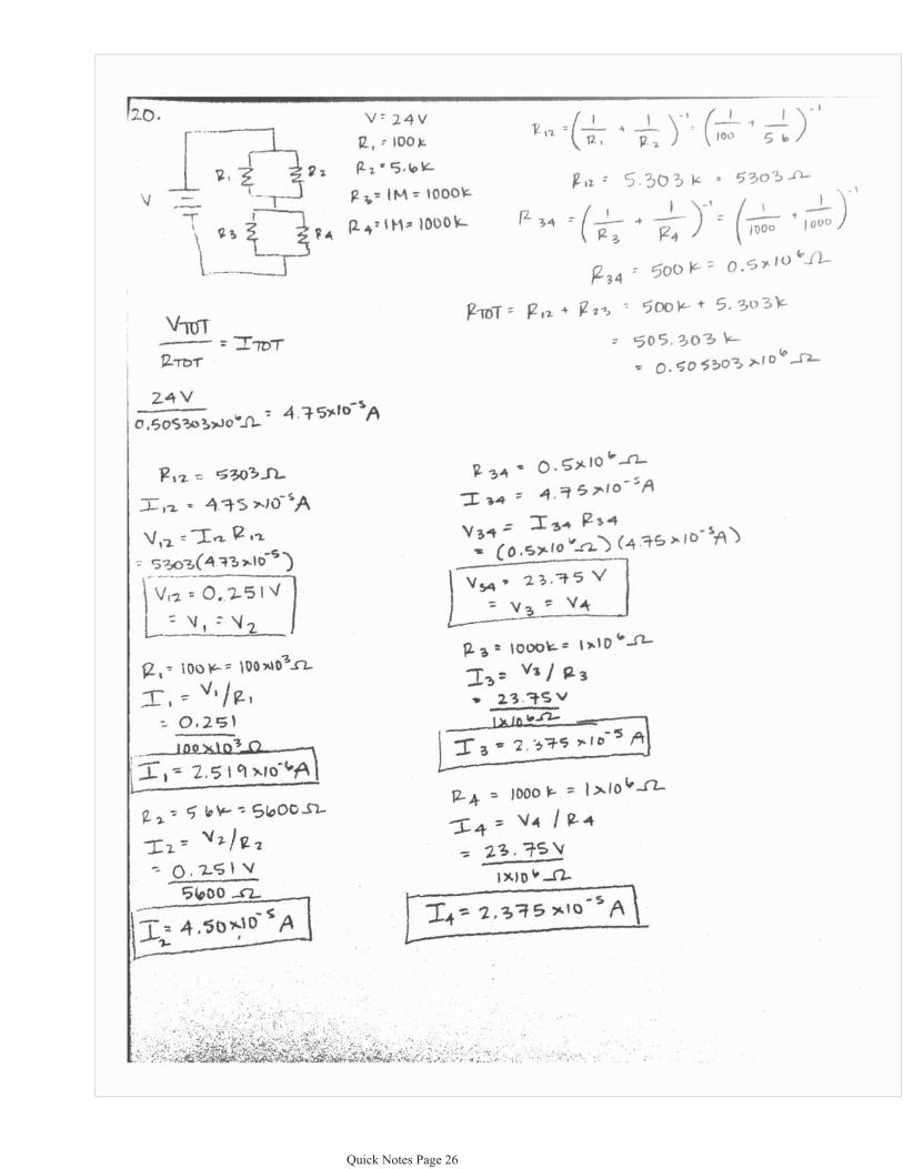
��� ���������� ������ ���
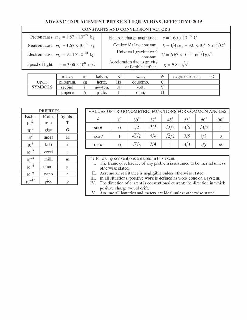
pm �� �
nm �� �
em �� �
c � �
e �� �
k pe� � � �
G �� � �
g �
�
W
�
�
� m�
�
q � � � � � � �
q
q
q �
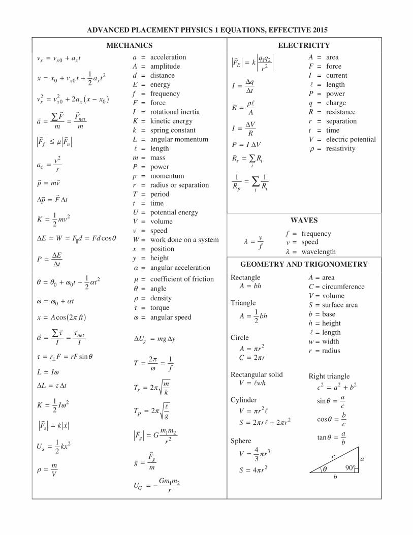
MECHANICS ELECTRICITY
0x x xa tà � �
20 0
12xx x t a� � � xt
�2 20 2x x xa x xà � � � 0
netFFa
m� ��
m
��
fF m� nF� �
2
ca �r
p mv�� �
p F tD D�� �
212
K mv�
cosE W F d Fd qD � � ��
EPt
DD
�
20 0
12
tq q w a� � � t
0 tw w a� �
� cos 2x A ftp�
net
I Itt
a � �� ��
sinr F rFt �� � q
L Iw�
L ttD � D
212
K Iw�
sF k x�� �
2
2sU kx� 1
mV
r �
a = acceleration A = amplitude d = distance E = energy f = frequency F = force I = rotational inertia K = kinetic energy k = spring constant L = angular momentum � = lengthm = mass P = power p = momentum r = radius or separation T = period t = time U = potential energy V = volume v = speed W = work done on a system x = position y = height a = angular acceleration
m = coefficient of friction q = angle r = density t = torque w = angular speed
gU mg yD � D
2Tf
pw
� � 1
2smTk
p�
2pTg
p� �
1 22g
m mF G
r�
�
gFg
m��
�
1 2G
Gm mU
r� �
1 22E
q qF k
r�
�
qI
tDD
�
RAr� �
VIRD�
P I VD�
si
R R� i
1 1
p iiR R
�
A = area F = force I = current � = lengthP = power q = charge R = resistance r = separation t = time V = electric potential r = resistivity
WAVES
vf
l � f = frequency v = speed l = wavelength
GEOMETRY AND TRIGONOMETRY
Rectangle A bh�
Triangle 12
A bh�
Circle 2A p�
2C p�r
r
Rectangular solid V wh� �
Cylinder
V rp� �2
2 2S r rp p� �� 2
Sphere 3
3V rp� 4
24S rp�
A = area C = circumference V = volume S = surface area b = base h = height � = lengthw = width r = radius
Right triangle
2 2 2c a b� �
sin ac
q �
cos bc
q �
tan ab
q �
c a
b90�q
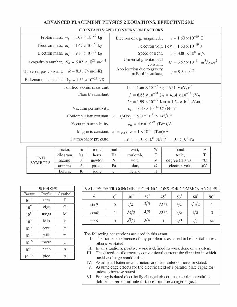
CONSTANTS AND CONVERSION FACTORS
Proton mass, 271.67 10 kgpm �� �
Neutron mass, 271.67 10 kgnm �� �
Electron mass, 319.11 10 kgem �� �
Avogadro’s number, 23 -10 6.02 10 molN � �
Universal gas constant, 8.31 J (mol K)R � �
Boltzmann’s constant, 231.38 10 J KBk �� �
Electron charge magnitude, 191.60 10 Ce �� �
1 electron volt, 191 eV 1.60 10 J�� �Speed of light, 83.00 10 m sc � �
Universal gravitational constant,
11 3 26.67 10 m kg sG �� � �
Acceleration due to gravityat Earth’s surface,
29.8 m sg �
1 unified atomic mass unit, 27 21 u 1.66 10 kg 931 MeV c�� � �� Planck’s constant, 34 156.63 10 J s 4.14 10 eV sh �� � � ��
25 31.99 10 J m 1.24 10 eV nmhc �� � � ��
Vacuum permittivity, 12 2 20 8.85 10 C N me �� � �
Coulomb’s law constant, 9 201 4 9.0 10 N m Ck pe� � � �
AVacuum permeability, 70 4 10 (T m)m p �� � �
Magnetic constant, 70 4 1 10 (T m)k m p �� � � �
5 1 atmosphere pressure, 5 21 atm 1.0 10 N m 1.0 10 Pa� � � �
UNIT SYMBOLS
meter, m kilogram, kgsecond, sampere, Akelvin, K
mole, mol hertz, Hz
newton, Npascal, Pajoule, J
watt, W coulomb, C
volt, Vohm,
henry, H
farad, F tesla, T
degree Celsius, C� W electron volt, eV
2
A
�
�
PREFIXES Factor Prefix Symbol
1012 tera T
109 giga G
106 mega M
103 kilo k
10�2 centi c
10�3 milli m
10�6 micro m
10�9 nano n
10�12 pico p
VALUES OF TRIGONOMETRIC FUNCTIONS FOR COMMON ANGLES
q �0
�30
�37 45� �
53 60� 90�
sinq 0 1 2 3 5 2 2 4 5 3 2 1
cosq 1 3 2 4 5 2 2 3 5 1 2 0
tanq 0 3 3 3 4 1 4 3 3 �
The following conventions are used in this exam. I. The frame of reference of any problem is assumed to be inertial unless
otherwise stated. II. In all situations, positive work is defined as work done on a system.
III. The direction of current is conventional current: the direction in whichpositive charge would drift.
IV. Assume all batteries and meters are ideal unless otherwise stated.V. Assume edge effects for the electric field of a parallel plate capacitor
unless otherwise stated.
VI. For any isolated electrically charged object, the electric potential isdefined as zero at infinite distance from the charged object.
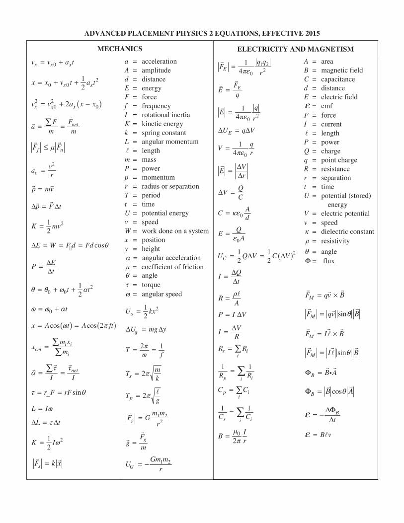
MECHANICS ELECTRICITY AND MAGNETISM
0x x xa tà � �
x x� � 20 0Ãx t � a t
21
x
�2 20 2x x xa x xà � � � 0
netFFa
m m� ��
��
f nF Fm�� �
2
car�
p mv�� �
p F tD D���
212
K mv�
cosE W F d Fd qD � � ��
EPt
DD
�
20 0
12
t tq q w a� � �
0 tw w a� �
� � cos cos 2x A t A fw� � tp
i icm
i
m xx
m�
net
I Itt
a � �� ��
sinr F rFt �� � q
L Iw�
L ttD D�
212
K Iw�
sF k x� ��
a = acceleration A = amplitude d = distance E = energy F = force f = frequency I = rotational inertia K = kinetic energy k = spring constant L = angular momentum � = lengthm = mass P = power p = momentum r = radius or separation T = period t = time U = potential energy v = speed W = work done on a system x = position y = height a = angular acceleration m = coefficient of friction q = angle t = torque w = angular speed
212sU kx�
gU mg yD D�
2 1Tf
pw
� �
2smTk
p�
2pTg
p� �
1 22g
m mF G
r�
�
gFg
m��
�
1 2G
Gm mU
r� �
1 22
0
14E
q qF
rpe�
�
EFE
q�
� �
20
14
qE
rpe�
�
EU q VD D�
0
14
qV
rpe�
VEr
DD
��
QV
CD �
0ACd
ke�
0
QE
Ae�
� 21 12 2CU Q V CD� � VD
QI
tDD
�
RAr� �
P I VD�
VIRD�
si
R R� i
1 1
p iiR R
�
pi
C C� i
1
s iC
� 1
iC
0
2IBr
mp
�
A = area B = magnetic field C = capacitance d = distance E = electric field e = emfF = force I = current � = lengthP = power Q = charge q = point charge R = resistance r = separation t = time U = potential (stored)
energy V = electric potential v = speed k = dielectric constant r = resistivity
q = angle F = flux
MF qv B� �� �
�
sinMF qv q�� �
B
MF I B� ����
�
sinMF I Bq����
�
B B AF � � ��
cosB B AqF ���
B
te DF
D� �
B ve � �
�
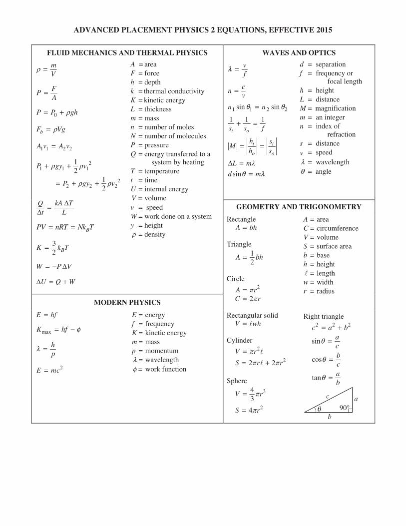
FLUID MECHANICS AND THERMAL PHYSICS
A = areaF = force h = depth k = thermal conductivity K = kinetic energy L = thickness m = mass n = number of moles N = number of molecules P = pressure Q = energy transferred to a
system by heating T = temperature t = time U = internal energy V = volume v = speed W = work done on a system y = height�r = density
mV
r �
FPA
�
0P P gr� � �h
bF Vgr�
1 1 2 2A v A v�
21 1
12
P gy vr� �
22 2
12
P gy vr r� � �
1r
2
kA TQt L
DD
�
BPV nRT Nk T� �
32 BK k� T
VW PD� �
U Q WD � �
MODERN PHYSICS
E = energy f = frequency K = kinetic energy � = mass p = momentum l = wavelength f = work function�
E hf�
maxK hf f� �
hp
l �
2E mc�
WAVES AND OPTICS
d = separation f = frequency or
focal lengthh = height L = distance M = magnification m = an integer n = index of
refraction s = distance � = speed l = wavelength q = angle�
vf
l �
cnÃ
�
1 1 2sin sinn nq � 2q
1 1
i os s f� � 1
i
o
hM
h� � i
o
ss
L mlD �sind mq l�
GEOMETRY AND TRIGONOMETRY
A = area C = circumference V = volume S = surface area b = base h = height � = length w = width r = radius
Rectangle A � bh
Triangle 12
A b� h
Circle 2A rp�
2C rp�
Rectangular solid V w� � h
r
Cylinder 2V rp� �
22S rp p� �� 2
Sphere 34
3V p� r
24S rp�
Right triangle 2 2c a� � b2
sin ac
q �
cos bc
q �
tan ab
q �
c a
b90�q