advanced microprocessors & microcontroller /unit-...
TRANSCRIPT
Advanced Microprocessors
& Microcontroller /Unit-
1/µP8086/Electronics &
Telecommunication Engg.

UNIT-I :Introduction to 16 bit microprocessors. 8086/8088
CPU architecture, memory organization,
interfacing addressing modes, Instruction set,
programming examples, pseudo opcodes,
assembler directives.
UNIT-II :Interfacing of peripherals 8255,8253 & 8251.
Interfacing of ADC & DAC, stepper motor, serial
communication standards RS232, I C Bus.

UNIT-III :Architecture, organization operation & interfacing
of 8259, ICWs, OCWS, Cascading 8279-
keyboard display mode, sensor matrix mode,
command words and programme DTMF Trans
receiver (Mittel 8880)
Real time clock, DS 1307, EEPROM.
UNIT-IV :8086/88 maximum mode 8087 architecture,
80386 architecture, real and protected mode
8237 DMA controller, organization, control
words.

UNIT-V Introduction to 8051 family architecture, pin
diagram, operation, ports, addressing modes,
internal & external memory, SFR, flags,
organization, counters and timers, serial
communication
UNIT-VI 8051 instruction set, interrupts, programming
exercises for interfaced with keyboard, LED
matrix, time delays, serial communications

Learning Objective
1.Introduction to 16 bit microprocessors
2.8086/8088 CPU architecture
3.Memory organization
4.Interfacing
5.Addressing modes
6. Instruction set
7.Programming examples
8.Assembler directives

Intel 8086 CPU: An Intel 8086 CPU: An
IntroductionIntroduction
8086 Features
• 16-bit Arithmetic Logic Unit
• 16-bit data bus
• 20-bit address bus - 220 = 1,048,576 = 1 meg
The address refers to a byte in memory. In the 8086, bytes at even
addresses come in on the low half of the data bus (bits 0-7) and bytes at
odd addressescome in on the upper half of the data bus (bits 8-15).
The 8086 can read a 16-bit word at an even address in one operation and
at an odd address in two operations.
The least significant byte of a word on an 8086 family microprocessor is
at the lower address.

8086 Architecture8086 Architecture• The 8086 has two parts, the Bus Interface Unit (BIU) and the Execution Unit (EU).• The BIU fetches instructions, reads and writes data, and computes the 20-bit address.• The EU decodes and executes the instructions using the 16-bit ALU.• The BIU contains the following registers:
IP - the Instruction PointerCS - the Code Segment RegisterDS - the Data Segment RegisterSS - the Stack Segment RegisterES - the Extra Segment Register
The BIU fetches instructions using the CS and IP, written CS:IP, to constructthe 20-bit address. Data is fetched using a segment register (usually the DS) and an effective address (EA) computed by the EU depending on the addressing mode.
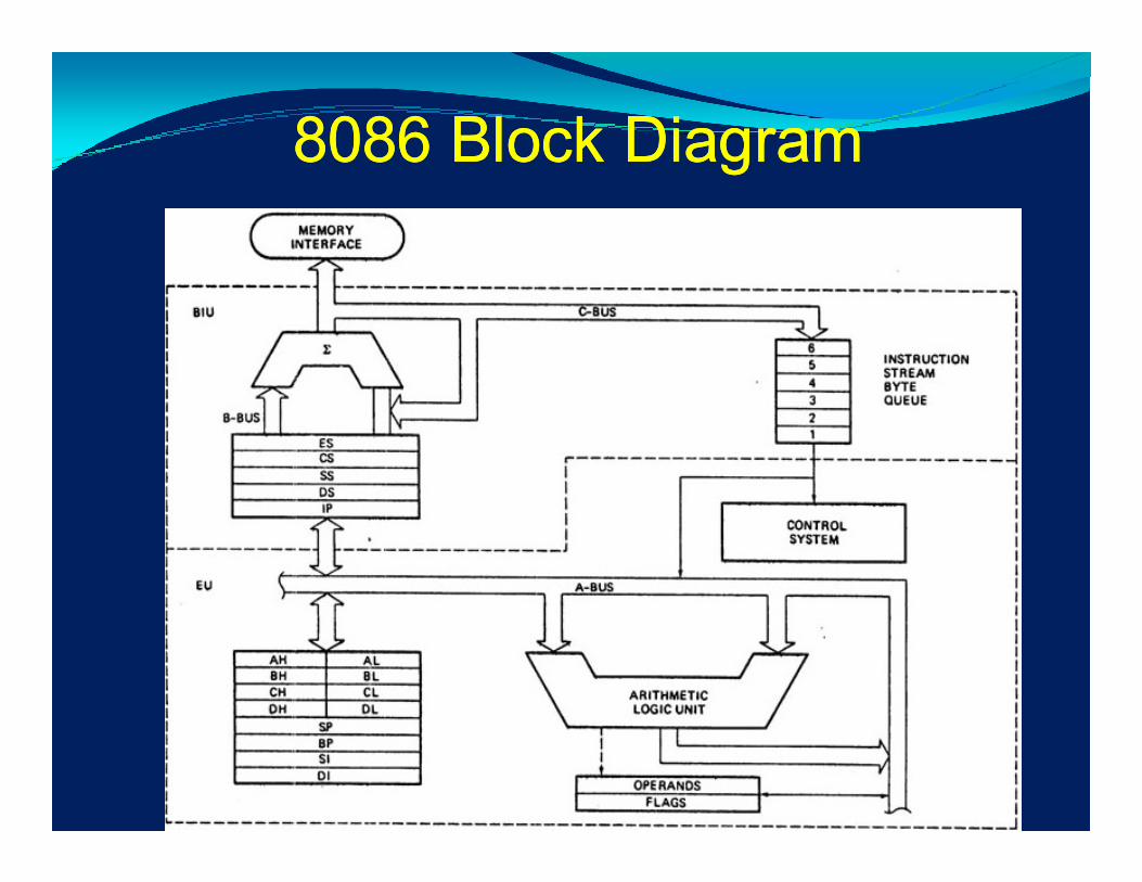
8086 Block Diagram8086 Block Diagram

The EU contains the following 16-bit registers:
AX - the AccumulatorBX - the Base RegisterCX - the Count RegisterDX - the Data Register
SP - the Stack Pointer BP - the Base Pointer SI - the Source Index RegisterDI - the Destination Register
These are referred to as general-purpose registers, although, as seen by their names, they often have a special-purpose use for some instructions.
The AX, BX, CX, and DX registers can be considered as two 8-bit registers, a High byte and a Low byte. This allows byte operations and compatibility with the previous generation of 8-bit processors, the 8080 and 8085. The 8-bit registers are:
AX --> AH,ALBX --> BH,BLCX --> CH,CLDX --> DH,DL
8086 Architecture 8086 Architecture
Default to stack segment

8086 Architecture8086 Architecture
The EU also contains the Flag Register which is a collection of condition bits and control bits. The condition bits are set or cleared by the execution of an instruction. The control bits are set by instructions to control some operation of the CPU.
Bit 0 - CF Carry Flag - Set by carry out of msbBit 2 - PF Parity Flag - Set if result has even parityBit 4 - AF Auxiliary Flag - for BCD arithmeticBit 6 - ZF Zero Flag - Set if result is zeroBit 7 - SF Sign Flag = msb of resultBit 8 - TF Single Step Trap FlagBit 9 - IF Interrupt Enable FlagBit 10 - DF String Instruction Direction FlagBit 11 - OF Overflow Flag
Bits 1, 3, 5, 12-15 are undefined.
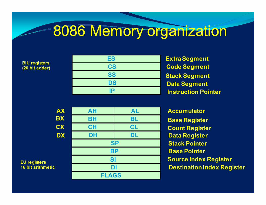
8086 Memory organization8086 Memory organization
ES
CS
SS
DS
IP
AH
BH
CH
DH
AL
BL
CL
DL
SP
BP
SI
DI
FLAGS
AXBX
CX
DX
Extra Segment
Code Segment
Stack Segment
Data Segment
Instruction Pointer
Accumulator
Base Register
Count RegisterData Register
Stack Pointer
Base Pointer
Source Index Register
Destination Index Register
BIU registers(20 bit adder)
EU registers16 bit arithmetic
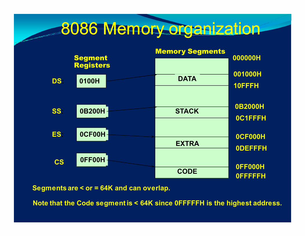
8086 Memory organization8086 Memory organization
CODE
DATA
STACK
EXTRA
0100H
0B200H
0CF00H
0FF00H
DS:
SS:
ES:
CS
001000H
0B2000H
0CF000H
0FF000H
10FFFH
0C1FFFH
0DEFFFH
0FFFFFH
000000HSegment Registers
Memory Segments
Segments are < or = 64K and can overlap.
Note that the Code segment is < 64K since 0FFFFFH is the highest address.

Interfacing
The memory locations 00000-FFFFF are designed as odd and evenbytes. To distinguish between odd and even bytes, the CPU provides a
signal called BHE (bus high enable). BHE and A0 are used to select theodd and even byte, as shown in the table below.

Addressing ModesAddressing Modes
DATA1 DW 25H DATA1 is defined as a word (16-bit) variable, i.e., amemory location that contains 25H.
DATA2EQU 20H DATA2 is not a memory locationbut a constant.
DirectAddressing
MOV AX,DATA1 [DATA1]→→→→ AX, the contents of DATA1 is put into AX.The CPU goes to memory toget data. 25H is put in AX.
ImmediateAddressing
MOV AX,DATA2 DATA2 = 20H→→→→ AX, 20H is put in AX.Does not go to memory toget data.Data is in the instruction.
MOV AX, OFFSET DATA1 The offset of SAM is just a number.
The assembler knows which mode to encode by the way the operands SAM andFRED are defined.
Assembler directive, DW = Define Word
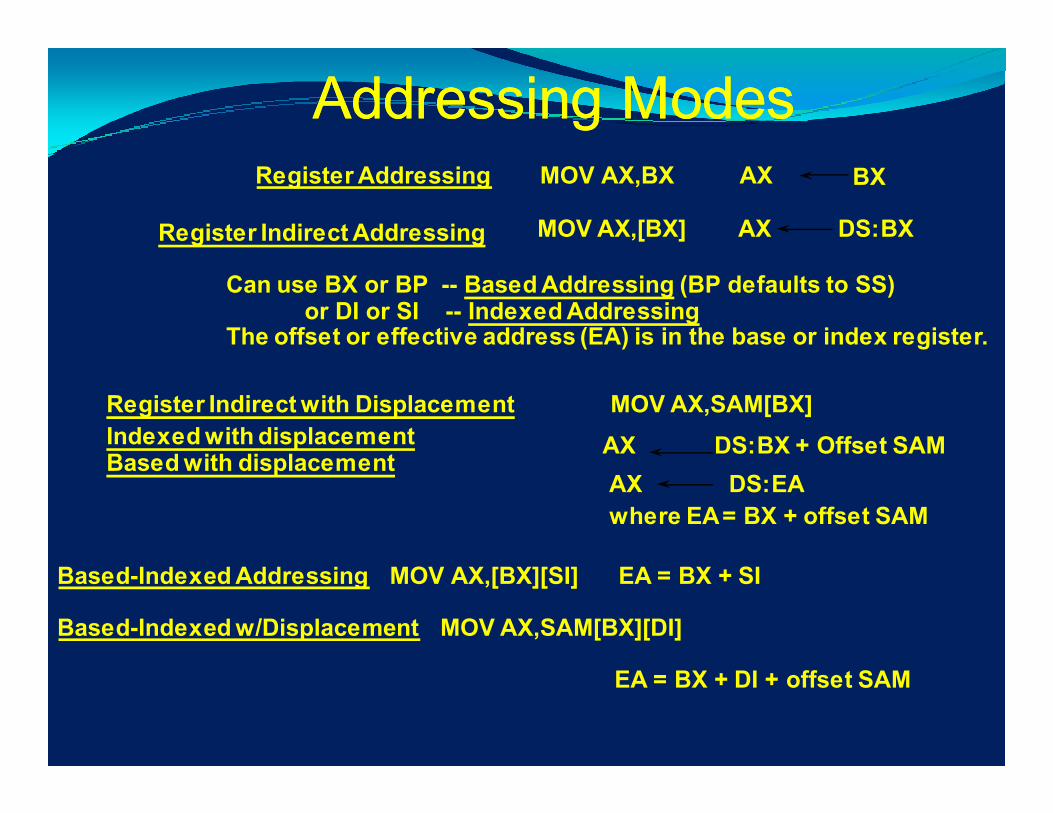
Addressing ModesAddressing ModesRegister Addressing MOV AX,BX AX BX
Register Indirect Addressing MOV AX,[BX] AX DS:BX
Can use BX or BP -- Based Addressing (BP defaults to SS)or DI or SI -- Indexed Addressing
The offset or effective address (EA) is in the base or index register.
Register Indirect with Displacement MOV AX,SAM[BX]
AX DS:BX + Offset SAMIndexed with displacementBased with displacement
Based-Indexed Addressing MOV AX,[BX][SI] EA = BX + SI
Based-Indexed w/Displacement MOV AX,SAM[BX][DI]
EA = BX + DI + offset SAM
AX DS:EA
where EA = BX + offset SAM

Addressing ModesAddressing Modes
Branch Related Instructions
Intrasegment(CS does not change)
Direct -- IP relative displacementnew IP = old IP + displacementAllows program relocation withno change in code.
Indirect -- new IP is in memory or a register.All addressing modes apply.
Intersegment Direct -- new CS and IP are encoded in(CS changes) the instruction.
Indirect -- new CS and IP are in memory.All addressing modes applyexcept immediate and register.
NEAR JUMPS and CALLS
FAR
Assembly LanguageAssembly Language
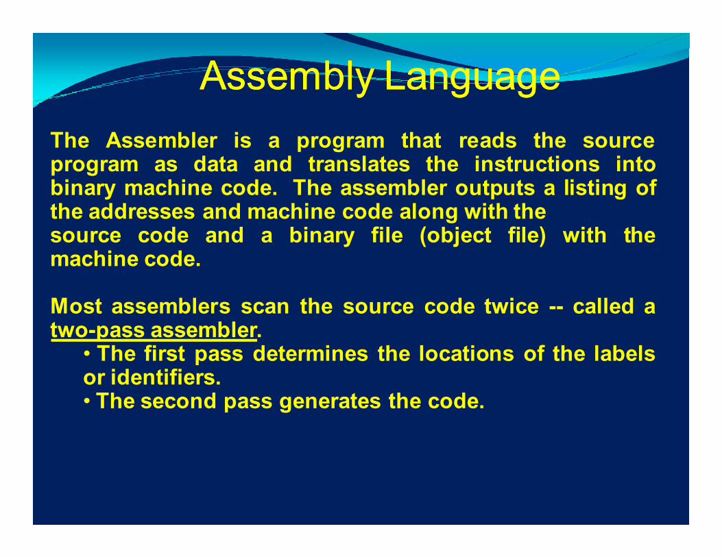
The Assembler is a program that reads the sourceprogram as data and translates the instructions intobinary machine code. The assembler outputs a listing ofthe addresses and machine code along with thesource code and a binary file (object file) with themachine code.
Most assemblers scan the source code twice -- called atwo-pass assembler.
• The first pass determines the locations of the labelsor identifiers.• The second pass generates the code.
Assembly LanguageAssembly Language
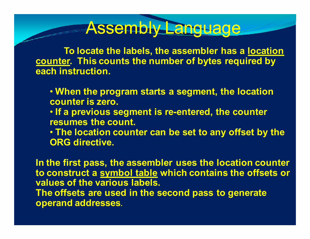
To locate the labels, the assembler has a location counter. This counts the number of bytes required by each instruction.
• When the program starts a segment, the location counter is zero.• If a previous segment is re-entered, the counter resumes the count.• The location counter can be set to any offset by the ORG directive.
In the first pass, the assembler uses the location counter to construct a symbol table which contains the offsets or values of the various labels.The offsets are used in the second pass to generate operand addresses.
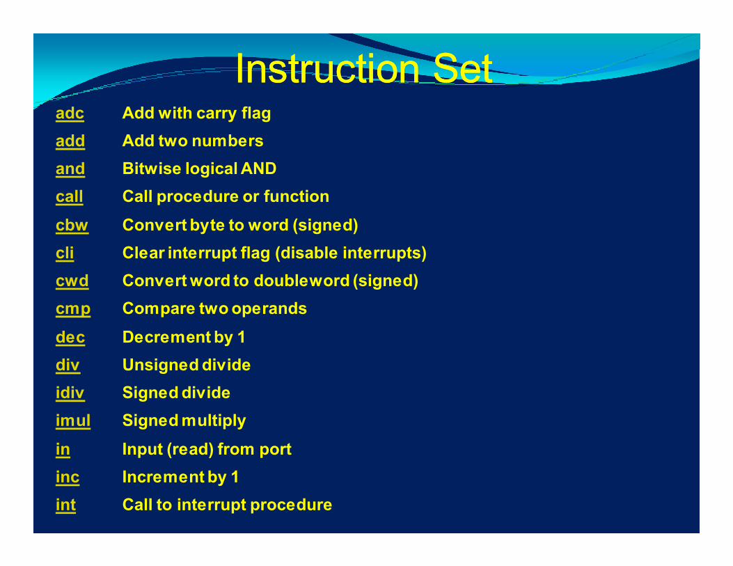
adc Add with carry flag
add Add two numbers
and Bitwise logical AND
call Call procedure or function
cbw Convert byte to word (signed)
cli Clear interrupt flag (disable interrupts)
cwd Convert word to doubleword (signed)
cmp Compare two operands
dec Decrement by 1
div Unsigned divide
idiv Signed divide
imul Signed multiply
in Input (read) from port
inc Increment by 1
int Call to interrupt procedure
Instruction SetInstruction Set

iret Interrupt return
j?? Jump if ?? condition met
jmp Unconditional jump
lea Load effective address offset
mov Move data
mul Unsigned multiply
neg Two's complement negate
nop No operation
not One's complement negate
or Bitwise logical OR
out Output (write) to port
pop Pop word from stack
popf Pop flags from stack
push Push word onto stack
Instruction Set (Contd.)Instruction Set (Contd.)
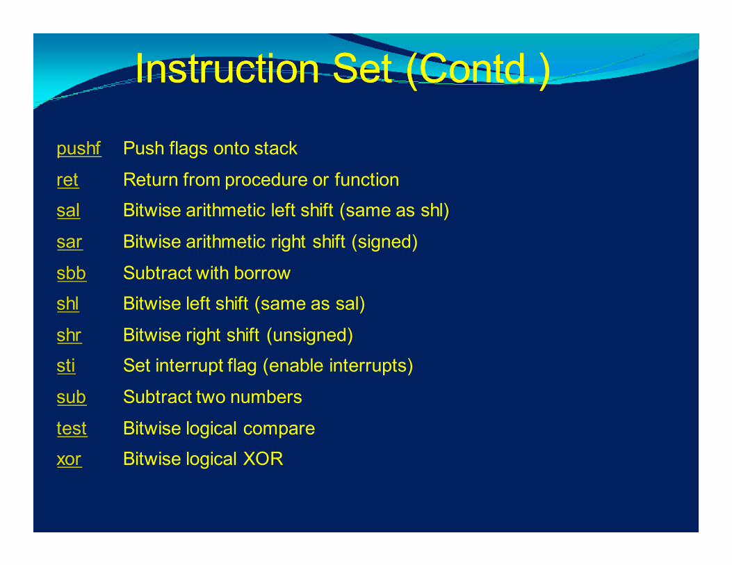
pushf Push flags onto stack
ret Return from procedure or function
sal Bitwise arithmetic left shift (same as shl)
sar Bitwise arithmetic right shift (signed)
sbb Subtract with borrow
shl Bitwise left shift (same as sal)
shr Bitwise right shift (unsigned)
sti Set interrupt flag (enable interrupts)
sub Subtract two numbers
test Bitwise logical compare
xor Bitwise logical XOR
Instruction Set (Contd.)Instruction Set (Contd.)
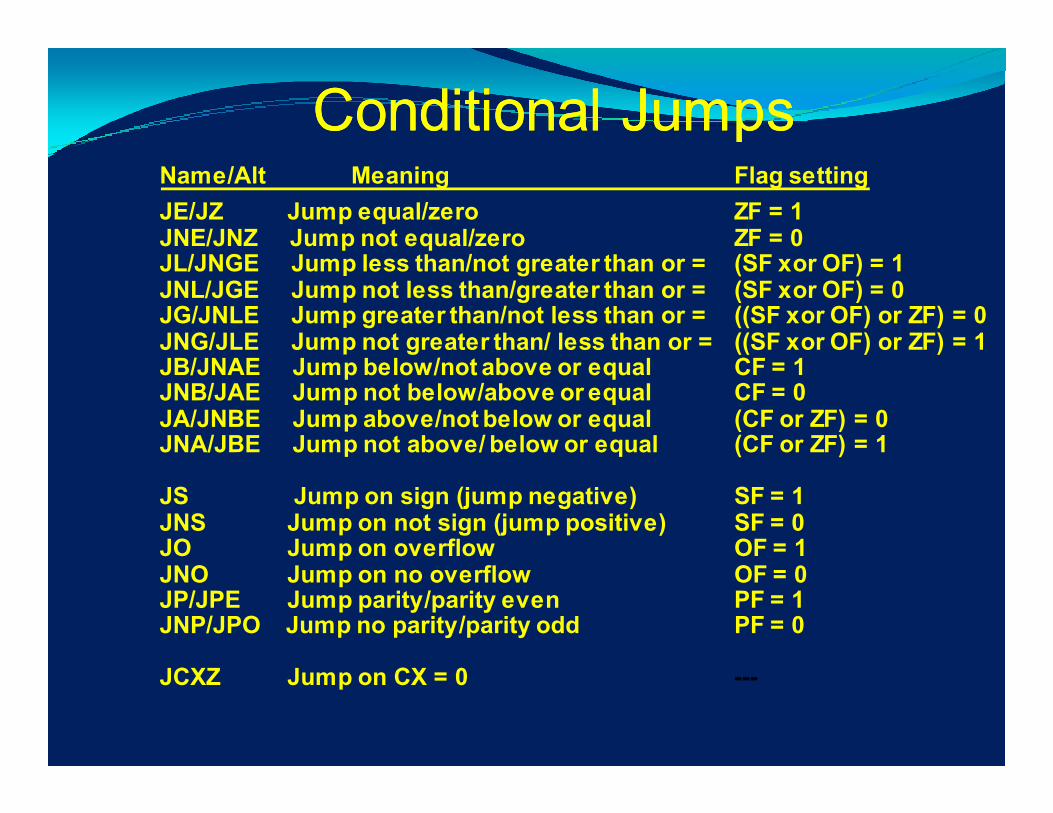
Conditional JumpsConditional JumpsName/Alt Meaning Flag setting
JE/JZ Jump equal/zero ZF = 1JNE/JNZ Jump not equal/zero ZF = 0JL/JNGE Jump less than/not greater than or = (SF xor OF) = 1JNL/JGE Jump not less than/greater than or = (SF xor OF) = 0JG/JNLE Jump greater than/not less than or = ((SF xor OF) or ZF) = 0JNG/JLE Jump not greater than/ less than or = ((SF xor OF) or ZF) = 1JB/JNAE Jump below/not above or equal CF = 1JNB/JAE Jump not below/above or equal CF = 0JA/JNBE Jump above/not below or equal (CF or ZF) = 0JNA/JBE Jump not above/ below or equal (CF or ZF) = 1
JS Jump on sign (jump negative) SF = 1JNS Jump on not sign (jump positive) SF = 0JO Jump on overflow OF = 1JNO Jump on no overflow OF = 0JP/JPE Jump parity/parity even PF = 1JNP/JPO Jump no parity/parity odd PF = 0
JCXZ Jump on CX = 0 ---

ADD
The "ADD" instruction will add together two operands. The results is stored in the the
first one.
add reg,reg
add reg,memadd mem,reg
add mem,con
Example:
add ax,10 ; the ax<-ax+10
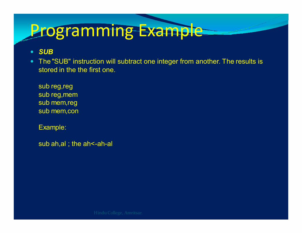
Programming Example� SUB
� The "SUB" instruction will subtract one integer from another. The results is
stored in the the first one.
sub reg,reg
sub reg,memsub mem,reg
sub mem,con
Example:
sub ah,al ; the ah<-ah-al
Hindu College, Amritsar.

More Assembler DirectivesMore Assembler Directives
ASSUME Tells the assembler what segments to use.
SEGMENT Defines the segment name and specifies that the code that follows is in that segment.
ENDS End of segment
ORG Originate or Origin: sets the location counter.
END End of source code.
NAME Give source module a name.
DW Define word
DB Define byte.
EQU Equate or equivalence
LABEL Assign current location count to a symbol.
$ Current location count

SummarySummary
1.Introduction to 16 bit
microprocessors
2.8086/8088 CPU architecture
3.Memory organization
4.Interfacing
5.Addressing modes
6. Instruction set
7.Programming examples
8.Assembler directives

ReferencesReferences
1.Programming & Interfacing of 8086/80888,
D.V.Hall, TMH.
2. Intel Reference Manuals, Microprocessors
& Microcontrollers:Intel
3. Advances Microprocessor & peripherals,
A.K.Ray, (TMH)