advanced micro controls inc. - amci of contents 4 advanced micro controls inc. chapter 4: installing...
TRANSCRIPT

MICRO CONTROLS INC.ADVANCED
User
M
anual
Manual #: 940-0A090

GENERAL INFORMATION
Important User InformationThe products and application data described in this manual are useful in a wide variety of different applica-tions. Therefore, the user and others responsible for applying these products described herein are responsible for determining the acceptability for each application. While efforts have been made to provide accurate infor-mation within this manual, AMCI assumes no responsibility for the application or the completeness of the information contained herein.UNDER NO CIRCUMSTANCES WILL ADVANCED MICRO CONTROLS, INC. BE RESPONSIBLE OR LIABLE FOR ANY DAMAGES OR LOSSES, INCLUDING INDIRECT OR CONSEQUENTIAL DAM-AGES OR LOSSES, ARISING FROM THE USE OF ANY INFORMATION CONTAINED WITHIN THIS MANUAL, OR THE USE OF ANY PRODUCTS OR SERVICES REFERENCED HEREIN.No patent liability is assumed by AMCI, with respect to use of information, circuits, equipment, or software described in this manual.The information contained within this manual is subject to change without notice.This manual is copyright 2014 by Advanced Micro Controls Inc. You may reproduce this manual, in whole or in part, for your personnal use, provided that this copyright notice is included. You may distribute copies of this complete manual in electronic format provided that they are unaltered from the version posted by Advanced Micro Controls Inc. on our official website: www.amci.com. You may incorporate portions of this documents in other literature for your own personal use provided that you include the notice “Portions of this document copyright 2014 by Advanced Micro Controls Inc.” You may not alter the contents of this document or charge a fee for reproducing or distributing it.
Standard WarrantyADVANCED MICRO CONTROLS, INC. warrants that all equipment manufactured by it will be free from defects, under normal use, in materials and workmanship for a period of [18] months. Within this warranty period, AMCI shall, at its option, repair or replace, free of charge, any equipment covered by this warranty which is returned, shipping charges prepaid, within eighteen months from date of invoice, and which upon examination proves to be defective in material or workmanship and not caused by accident, misuse, neglect, alteration, improper installation or improper testing.The provisions of the "STANDARD WARRANTY" are the sole obligations of AMCI and excludes all other warranties expressed or implied. In no event shall AMCI be liable for incidental or consequential damages or for delay in performance of this warranty.
Returns PolicyAll equipment being returned to AMCI for repair or replacement, regardless of warranty status, must have a Return Merchandise Authorization number issued by AMCI. Call (860) 585-1254 with the model number and serial number (if applicable) along with a description of the problem during regular business hours, Monday through Friday, 8AM - 5PM Eastern. An "RMA" number will be issued. Equipment must be shipped to AMCI with transportation charges prepaid. Title and risk of loss or damage remains with the customer until shipment is received by AMCI.
24 Hour Technical Support Number24 Hour technical support is available on this product. If you have internet access, start at www.amci.com. Product documentation and FAQ’s are available on the site that answer most common questions.If you require additional technical support, call (860) 583-7271. Your call will be answered by the factory dur-ing regular business hours, Monday through Friday, 8AM - 5PM Eastern. During non-business hours an auto-mated system will ask you to enter the telephone number you can be reached at. Please remember to include your area code. The system will page an engineer on call. Please have your product model number and a description of the problem ready before you call.
We Want Your FeedbackManuals at AMCI are constantly evolving entities. Your questions and comments on this manual are both wel-comed and necessary if this manual is to be improved. Please direct all comments to: Technical Documenta-tion, AMCI, 20 Gear Drive, Terryville CT 06786, or fax us at (860) 584-1973. You can also e-mail your questions and comments to [email protected]
ADVANCED MICRO CONTROLS INC.

TABLE OF CONTENTS
General InformationImportant User Information ..................... 2Standard Warranty ................................... 2Returns Policy .......................................... 224 Hour Technical Support Number ........ 2We Want Your Feedback ......................... 2
About this ManualAudience .................................................. 7Applicable Units ...................................... 7Trademark Notices ................................... 7Revision Record ....................................... 7Navigating this Manual ............................ 7Manual Conventions ................................ 8Where To Go From Here ......................... 8
Chapter 1: Introduction to the ANS1AnyNET-I/O ............................................ 9The ANS1 ................................................ 9Physical Description ................................ 10
Front Panel ..................................... 10Status LED’s .................................. 11I/O Connectors ............................... 12Power Connector ........................... 12Web Interface Connector ............... 12Network Connections .................... 13
Compatible Transducers .......................... 13Compatible AMCI Transducers .... 13Compatible AMCI Encoders ......... 13Compatible Foreign Transducers .. 13
Programming Web Interface .................... 14Web Page Access Levels ............... 14
Module Specifications ............................. 14Electrical Specifications .......................... 15Connectors ............................................... 15
Chapter 2: Limit Switch Functionality
Global Machine Position ......................... 17Advanced Parameter Use .............. 18
Global Machine Speed ............................. 18
Chapter 2: Limit Switch Functionality (continued)
Limit Switch Outputs ............................... 19Limit Switch Offset ...................... 19Stitch Programming ...................... 20Limit Advances ............................. 21
Fixed Delays ............................. 21Variable Delays ........................ 22
Timed Limits ................................. 22Limit Output Enabling ............................. 23
Machine Speed Enabling .............. 23Simple ANDing ............................ 23Pulse ANDing ............................... 24Window ANDing .......................... 24Shift Register ANDing .................. 25
Shift Register Programming ..... 25Limit Switch Programming ...... 25Application Example ................ 25
Chapter 3: Additional FunctionalityBrake Monitor .......................................... 27
Stop Time Monitoring .................. 27Start Time Monitoring .................. 28
Die Protection Monitors ........................... 28Normally True Check ................... 28Normally False Check .................. 28Cyclic Check ................................. 29Constant Check ............................. 31Quick Check ................................. 33
Production Counters ................................. 34Part Cycle Counter ........................ 34Batch Counters 1, 2, 3 ................... 35Good Part Counter ........................ 35Machine Revolutions .................... 35Using Batch Counter Outputs ....... 35
Chapter 4: Installing the ANS1Module Installation .................................. 37
Module Location ........................... 37Safe Handling Guidelines ............. 37
Prevent Electrostatic Damage ... 37Prevent Debris From Entering
the Module ............................. 37Remove Power Before Servicing
in a Hazardous Environment . 37
20 Gear Drive, Plymouth Ind. Park, Terryville, CT 06786Tel: (860) 585-1254 Fax: (860) 584-1973 http://www.amci.com
3

Table of Contents
Chapter 4: Installing the ANS1(continued)
Module Mounting ......................... 38Dimensions ............................... 38Compatible DIN Rail ................ 38Installing IC-5 Connectors ....... 39Mounting the AnyNET-I/O
Module ................................... 39Stack Addressing .......................... 39
Powering the Module ............................... 40Required Power ............................. 40Wiring ........................................... 40
Transducer Installation ............................. 40AMCI Engineering Data Download Location ....................... 40AMCI Transducer Mounting
Guidelines ................................... 41
Transducer Cabling .................................. 41Suggested Cable ............................ 41Installation Guidelines .................. 42Single Resolver Transducers ........ 42Single Resolvers ........................... 43
Foreign Transducers ................................. 43Quadrature Encoder Installation ............... 44
AMCI Compatible Encoders ........ 44Differential Wiring ....................... 44Single Ended Wiring ..................... 45
Relay Board Installation ........................... 45DIN Rail / Panel Mount Conversion .................................... 46RB-7 Outline Drawing .................. 46RB-8 Outline Drawing .................. 47Compatible Relays ........................ 47Connections to the ANS1 ............. 48Powering the RB Boards ............... 48
I/O Wiring ................................................ 49Relay Board Inputs ....................... 49Relay Board Outputs ..................... 49ANS1 Inputs ................................. 50ANSI Outputs ............................... 51Encoder Output Wiring ................. 52Slave Module Wiring .................... 52
HTTP Interface ......................................... 52
Chapter 5: Output Data FormatCommand Word ....................................... 53Command Block 0: Clear Errors Only ..... 53Command Block 1: Define Return Data
and I/O Forces ........................................ 54Command Word Bits ..................... 54Return Data Attribute Number ...... 55Output Force Words ...................... 55Input Force Words ......................... 55Command Block 2:
Global Machine Configuration ... 56Command Word Bits ..................... 56Global Machine Bit Parameters
(Word 1) ..................................... 57
Command Block 3: Program Limit Setpoints ........................ 58
Command Word Bits ..................... 58LS Setpoint Pair Data Format ....... 59
Command Block 4: Adjust LS Setpoint Positions .................. 60
Command Word Bits ..................... 60
Command Block 5: Program LS Timing Parameters ............. 61
Command Word Bits ..................... 61
Command Block 6: Program LS Enabling Parameters .......... 62
Command Word Bits ..................... 62
Command Block 7: Program Die Protection Parameters ....... 65
Command Word Bits ..................... 65
Command Block 8: Program Brake Monitor Parameters ....... 67
Command Word Bits ..................... 67
Command Block 9: Program Shift Register Parameters ....... 68
Command Word Bits ..................... 68
Command Block 10: Program Production Cycle Parameters ... 69
Command Word Bits ..................... 69
Command Block 11: Program Production Counter Parameters .............. 70
Word 1: Counter Number .............. 70Word 0: Command Word Bits ...... 71
Command Block 15: Save/Restore Program ............................ 72
Command Word Bits ..................... 72Word 1 Values ............................... 72
ADVANCED MICRO CONTROLS INC.4

Table of Contents
Chapter 6: Input Data FormatAvailable Data Attribute Blocks .............. 73
Data Attribute Number .................. 73
Status Word 0 ........................................... 73Bit Values ...................................... 74
Data Attribute 0: Global Setup Data ................................. 75
Data Attribute 1: LS Setpoint Programming Data ............ 76
Data Attribute 2: LS Output Adjustments Data ................ 77
Data Attribute 3: Enabling Input Programming Data ....... 78
Data Attribute 4: Die Monitor Setup Data ........................ 79
Data Attribute 5: Brake Monitor Setup Data .................... 80
Data Attribute 6: Shift Register Setup Data ...................... 81
Data Attribute 7: Production Cycle Setup Data ................ 81
Data Attribute 8: Counter Setup Data ............................... 82
Data Attribute 16: Machine Status Data ............................. 83
Data Attribute 17: Counter Value Data .............................. 85
Data Attribute 18: Die Monitor Data .................................. 86
Data Attribute 19: Brake Monitor and Output Advance Data ..................... 87
Data Attribute 20: Shift Register Data ................................ 88
20 Gear Drive, Plymouth Ind. Park, Terryville, CT 06786Tel: (860) 585-1254 Fax: (860) 584-1973 http://www.amci.com
5

Table of Contents
Notes
ADVANCED MICRO CONTROLS INC.6

ABOUT THIS MANUAL
Audience This manual explains the set-up, installation, and operation of AMCI’s ANS1 AnyNET-I/O Programmable Limit Switch module. It is written for the engineer responsible for incorporating these modules into a design, as well as the engineer or technician responsible for its actual installation.
Applicable UnitsThis manual applies to all ANS1 modules, including those that have an integral network connection. Exam-ples of these modules includes the ANS1E with an integral Ethernet port. Integral network connections allow the ANS1 to connect itself, and up to five other modules, to an industrial network.
If you have an ANS1 module with a network interface, you will have to refer to the appropriate AnyNET-I/O Network Interface manual for information on connecting the module to your network. These manuals can be found in the PDF document section of our website at www.amci.com/documents.asp
The AnyNET-I/O product line is constantly evolving. Check our website, www.amci.com for the latest information on available modules and network interfaces in the AnyNET-I/O line.
Trademark NoticesThe AMCI logo is a trademark of Advanced Micro Controls Inc.
All other trademarks contained herein are the property of their respective holders.
Revision RecordThis manual, 940-0A090, is the first revision of this manual. It was released December 18th, 2014.
Navigating this ManualThis manual is designed to be used in both printed and on-line formats. Its on-line form is a PDF document, which requires Adobe Acrobat Reader version 7.0+ to open it. The manual is laid out with an even number of pages in each chapter. This makes it easier to print a chapter to a duplex (double sided) printer.
Bookmarks of all the chapter names, section headings, and sub-headings were created in the PDF file to help navigate it. The bookmarks should have appeared when you opened the file. If they didn’t, press the F5 key on Windows platforms to bring them up.
Throughout this manual you will find blue text that functions as a hyperlink in HTML documents. Clicking on the text will immediately jump you to the referenced section of the manual. If you are reading a printed manual, most links include page numbers. You will also find red text that functions as a hyperlink. These links will bring you to the AMCI website. Note that after clicking on a red link, the program may ask for con-firmation before connecting to the Internet.
The PDF file is password protected to prevent changes to the document. You are allowed to select and copy sections for use in other documents and, if you own Adobe Acrobat version 7.0 or later, you are allowed to add notes and annotations.
Read this chapter to learn how to navigate through this manual and familiarize yourself with the conventions used in it. The last section of this chapter high-lights the manual’s remaining chapters and their target audience.
20 Gear Drive, Plymouth Ind. Park, Terryville, CT 06786Tel: (860) 585-1254 Fax: (860) 584-1973 http://www.amci.com
7

ABOUT THIS MANUAL
Manual ConventionsThree icons are used to highlight important information in the manual:
NOTES highlight important concepts, decisions you must make, or the implications of those decisions.
CAUTIONS tell you when equipment may be damaged if the procedure is not followed properly.
WARNINGS tell you when people may be hurt or equipment may be damaged if the proce-dure is not followed properly.
The following table shows the text formatting conventions:
Where To Go From HereThis manual contains information that is of interest to everyone from engineers to operators. The table below gives a brief description of each chapter’s contents to help you find the information you need to do your job.
Format Description
Normal Font Font used throughout this manual.
Emphasis Font Font used the first time a new term is introduced.
Cross Reference When viewing the PDF version of the manual, clicking on the cross reference text jumps you to referenced section.
HTML ReferenceWhen viewing the PDF version of the manual, clicking on the HTML reference text will open your default web browser to the referenced web page.
CHP Num. Chapter Title Intended Audience
1 Introduction to the ANS1
Anyone new to the ANS1. This chapter gives a basic overview of the features available on the unit, typical applications, and electri-cal specifications.
2 Limit Switch Functionality
Anyone that needs detailed information on the limit switch features available on the ANS1, including how the ANS1 calculates machine position, limit switch programming, and how to use the output enable features.
3 Additional Functionality
Anyone that needs detailed information on the additional function-ality available on the ANS1, including brake monitoring, die pro-tection, and production counters.
4 Installing the ANS1 Anyone that needs detailed information on installing the ANS1, transducers, relay boards, and I/O wiring.
5 Output Data Format Anyone that needs information on the format of the data written to the ANS1.
6 Input Data Format Anyone that needs information on the format of the data retrieved from the ANS1.
ADVANCED MICRO CONTROLS INC.8

20 Gear Drive, Plymouth IndTel: (860) 585-1254 Fax: (8
CHAPTER 1
INTRODUCTION TO THE ANS1AnyNET-I/OThe ANS1 is an expansion to the AnyNET-I/O product line from AMCI. The concept of this product line is simple: specialty and/or high speed I/O that can be attached to any popular industrial net-work; hence the name AnyNET-I/O.
AnyNET-I/O is designed for a broad range of applications, from small machines with a single control enclosure, to large machines that use distributed I/O extensively to minimize wiring costs.
What makes the AnyNET-I/O line different is that all of the mod-ules are available with or without a network interface. Eliminating the need for a separate networking module lowers the total cost of ownership for all applications, but especially for the cost sensitive small machines that only require one or two sophisticated func-tions.
Like many modern controllers, AnyNET-I/O modules are designed to be DIN rail mounted. Up to six AnyNET-I/O modules can be stacked together and accessed over a single network inter-face. “Stacking” is accomplished through a small backplane con-nector that snaps into the DIN rail before the AnyNET-I/O modules are installed. These connectors allow the AnyNET-I/O modules to communicate with each other. To the network, the stack of modules appear as one continuous block of I/O words.
The ANS1The ANS1 is a Programmable Limit Switch module that accepts 12 to 24 Vdc as its power source. The ANS1 offers the following functionality:
A total of forty programs that can be stored on the ANS1. If the ANS1 is attached to a host controller, additional programs can be stored on the host.
Eight relay and eight DC outputs. These outputs can be configured as limit switch, fault, counter over-flow, or general purpose outputs.
Sixteen DC inputs. Inputs can be used to condition the outputs (Enable ANDing), preset machine or limit switch positions, or as general purpose inputs.
Four setpoint pairs per limit switch as well as On/Off advances and timer output functionality. Three different Enable ANDing tests for conditioning the limit switch outputs. RPM ANDing to condition the outputs based on the speed of the machine. 256-bit Shift Register for machines that require multiple turns to create a single part. Sixteen programmable Die Protection Monitors with fault counters that can monitor five different types
of events to guarantee proper machine operation. Brake Monitor that reports both starting and stopping time of the machine. A total of six counters that include three batch counters, a total machine revolutions counter, a total
parts counter, and a total good parts counter.
This manual is designed to get you quickly up and running with the ANS1 Pro-grammable Limit Switch Module. It is possible to purchase an ANS1 with or with-out a network interface. This manual only covers the functionality unique to the ANS1. Information on connecting to the network interface is available in the appropriate AnyNET-I/O Network Interface manual available on the AMCI website.
Figure 1.1 AnyNET-I/O Module Stack
. Park, Terryville, CT 0678660) 584-1973 http://www.amci.com
9

Introduction to the ANS11
The ANS1 (continued)It offers a single transducer input for position feedback that can either be a resolver based transducer or an incremental encoder. If additional I/O points are needed, multiple ANS1 modules can be slaved together. One ANS1 interfaces with the position transducer and broadcasts the position value to the remaining ANS1 modules over a high speed serial link.
An AMCI AnyNET-I/O Stack is limited to six modules, and all of them can be ANS1 modules. This gives you up to ninety-six I/O points in a single AnyNET-I/O Stack. The slave interface is an RS485 serial link that can conservatively drive sixty-four modules. If your application require more than six modules, you can slave them together, but you will need multiple network connections to program them.
Like all AnyNET-I/O modules, the ANS1 can be attached to a host controller through vari-ous industrial networks including:
EtherNet/IP Modbus TCP Modbus RTU Profibus-DP
The ANS1 is the first AnyNET-I/O module to include an integral web server, which allows you to program the ANS1 from any web browser. This allows you to run the ANS1 as an independent product, without the need of a host controller. If slaving multiple modules together, each module has to be programmed separately. The IP address of the web server is programmable, so all of the modules can be brought into one ethernet switch and pro-grammed from one web browser connection.
Physical Description
Front Panel
Figure 1.3 shows the layout of the front panel. Compared to most of the other AnyNET-I/O modules, the ANS1 is a double width module. Even though it is twice the width, it only takes one slot in the AnyNET-I/O stack.
Relay Board Connector. Allow the ANS1 to be con-nected to AMCI RB-7 or RB-8 relay boards. These relay boards give you access to all sixteen input and output points. I/O on the relay board are numbered 1 through 8 when programming the ANS1.
Relay Cable Ground Lug. Use this point to ground the shields on the relay board cable.
Stack Address DIP Switch. Used to set the address of the ANS1 in an AnyNET-I/O Stack. If the ANS1 is used as the network host, then the module must have an address of zero. (All switches off.)
Figure 1.2 ANS1 Web Interface
ADDRESS
PLS
PWR FUSE
IN OUT
09 0913 13
10 1014 14
11 1115 15
12 1216 16
RelayBoard
ConnectorI/O StatusLED’s
RelayCable
GroundLug
StackAddressDIP Switch
Module Status LED
Figure 1.3 ANS1 Front Panel Callout
ADVANCED MICRO CONTROLS INC.10

Introduction to the ANS1 1
Physical Description (continued)Status LED’s
Figure is a close up of the front of the module that shows the locations of the ANS1 Status LED’s.
Power. States are off or solid green. If off, the module is without power or a hardware error has occurred. If on, the module and outputs are working normally.
Fuse. States are off or solid red. If off, the output drivers on the ANS1 are operating normally. If on, the one or more of the outputs are in an overload condition, and the internal resettable fuse has opened.Note that none of the outputs will conduct current if the FUSE LED is on.
Inputs 9 - 16. States are off or solid orange. If off, the input on the ANS1 is not receiving power. If on, the input is receiving power. Note that the input status LED’s only display the powered state of the inputs. They do not show the logical state of the input. If an input is programmatically forced on or off, this state will not be reflected in the LED’s.
Outputs 9 - 16. States are off or solid orange. The LED reflects the logical state of the output, including whether or not the output is forced on or off.
As shown in figure 1.3 on page 10 and figure 1.6 on page 12, a Module Status LED is located on the bottom of the module, below the relay board connector. This LED gives additional information on the state of the ANS1.
Table 1.1 Module LED States
LED State Module State
Solid Green Module and Transducer are operating normally.
Blinking Green One or more outputs are being forced on or off.
Solid Red
1) Non-Clearable Transducer Fault. (Most common occurrence)Signals from the resolver cannot be decoded. Most common cause is a wiring issue.
2) Module Fault. (Rare occurrence)Remove power, and remove all I/O connections. Restore power. If the error remains, contact AMCI for technical assistance. If the error clears, begin the process of removing power, installing one I/O connector, and applying power to the ANS1. Repeat the process until you discover the connector with the problem.
Blinking Red Clearable Resolver Transducer Fault. The transducer fault latch has been enabled on the ANS1. A Clear Errors command must be issued to clear the fault.
ADDRESS
PLS
PWR FUSE
IN OUT
09 0913 13
10 1014 14
11 1115 15
12 1216 16
Figure 1.4 Status LED’s
20 Gear Drive, Plymouth Ind. Park, Terryville, CT 06786Tel: (860) 585-1254 Fax: (860) 584-1973 http://www.amci.com
11

Introduction to the ANS11
Physical Description (continued)I/O Connectors
Figure shows the pinout of the Main and I/O connectors located on the top of the ANS1. Mating connectors are supplied with the ANS1. Additional connectors can be ordered from AMCI under the part number MS-2x11.
Figure 1.5 I/O Connector Pinout
Power Connector
As shown in figure 1.6 below, the power connector is located on the bottom of the module. The mating con-nector is included with the ANS1. Spares are available from AMCI under the part number MS-4M. They are also available from Phoenix Contact under their part number 187 80 37.
Figure 1.6 ANS1 Bottom View
Web Interface Connector
Figure 1.6 also shows the location of the Web Interface Connector. This RJ45 Ethernet connector accepts any standard CAT5 or CAT6 network cable and allows you to monitor and program the ANS1 over its built in web server. This allows you to program and use an ANS1 without a host controller.
1110987654321
1110987654321
1110987654321
1110987654321
-Ref (R2)+Sin (R3)
Shield-Z In/Out-B In/Out-A In/OutQuadDir
-RxD (Slave)-TxD (Slave)
ReservedReserved
ReservedShield
N.C.Input 9
Input 10Input 11Input 12Input 13Input 14Input 15Input 16
+Ref (R1)+Cos (S4)Com (S1,S2)+Z In/Out+B In/Out+A In/OutGround
+RxD (Slave)+TxD (Slave)
ReservedReserved
ReservedCommon+Vdc InOutput 9Output 10Output 11Output 12Output 13Output 14Output 15Output 16
1110987654321
1110987654321
1110987654321
1110987654321
J2 J4
J2 J4J1 J3
J1 J3
Power ConnectorWeb InterfaceConnector
ModuleStatus LED
ADVANCED MICRO CONTROLS INC.12

Introduction to the ANS1 1
Physical Description (continued)Network Connections
Figure 1.6 on the previous page also shows the location on the ANS1 that is reserved for network connec-tions. If your ANS1 has a network connection, such as the ANS1E for Ethernet networks, connection to the network will be made here. Refer to the appropriate AnyNET-I/O Network Interface manual for additional information.
Compatible TransducersThe ANS1 is compatible with resolver based transducers as well as quadrature incremental encoders. Resolver based transducers offer absolute position feedback and will survive the harshest of industrial envi-ronments. Encoders offer the ability to easily change the length of a single machine cycle. Note that the ANS1 does not decode the Z-channel of the encoder.
AMCI offers broad lines of transducers that are compatible with the ANS1.
Compatible AMCI Transducers
All R11X-J resolvers All R15X-J resolvers The HT-6 single turn transducer with the standard AMCI resolver All members of the H25 family of single turn transducers with the standard AMCI resolver All members of the HT-20 family of single turn transducers with the standard AMCI resolver All members of the HT-20-(x) family of multi-turn transducers with the standard AMCI resolver All members of the HT-400 family of single turn transducers with the standard AMCI resolver All members of the HT-400-(x) family of multi-turn transducers with the standard AMCI resolver
Further information on AMCI transducers can be found on our website starting at: http://www.amci.com/resolvers.asp
Compatible AMCI Encoders
All DC25 incremental encoders with differential outputs
Further information on AMCI incremental encoders can be found on our website starting at: http://www.amci.com/rotary-encoders/incremental-rotary-encoder.asp
Compatible Foreign Transducers
Popular resolver transducers from other manufacturers can be used with the ANS1. Most of them will require a Reference Module from AMCI to make the resolver compatible with the ANS1. The Reference Module is a single ended transformer that either raises or lowers the reference going out to the resolver so the return sig-nals are in the proper range for the ANS1.
Any incremental encoder with 5 volt differential output drivers is compatible with the ANS1. The ANS1 can also be used with encoders that use a higher voltage driver or have single ended outputs with the use of appro-priate current limiting resistors.
20 Gear Drive, Plymouth Ind. Park, Terryville, CT 06786Tel: (860) 585-1254 Fax: (860) 584-1973 http://www.amci.com
13

Introduction to the ANS11
Programming Web InterfaceThe ANS1 has an internal web server that allows you to program and use the module without a host control-ler. The web server is accessed through the RJ-45 pot on the bottom of the ANS1, below the relay board con-nector. The location of the connector is shown in figure 1.6 on page 12. The RJ-45 is an auto-sensing port. A computer can be directly connected to the port with a standard ethernet cable. A crossover cable is not nec-essary.
Programming the ANS1 from the web interface is password protected. There are four levels of access:
Visitor: (No password) Read only access Operator: (Default password = ‘123’) Can clear faults, reset/preset counters, and increment/decre-
ment limit setpoints. Supervisor: (Default password = ‘456’) Can perform all Operator functions as well as full limit
switch programming, counter setup, and die protection setup. Master: (Default password = ‘987’) Access to all functions, including brake monitor setup, IP set-
tings, and password settings.
Passwords are made up of alphanumeric characters and can be up to twelve characters in length.
Web Page Access Levels
If you attempt to use a function that is not allowed for your access level, the ANS1 will bring you to the User Log In screen and wil either present you with the password screen, or with a button that allows you to logout.
Table 1.2 Web Page Access Levels
Screen Description Master Supervisor Operator
Stored Programs All Functions All Functions Load Only
Machine Status All levels can clear a transducer fault.
I/O States All Functions All Functions View Only
Counters All Functions All Functions Cannot Preset Program Cycles
Faults All Functions All Functions All Functions
Shift Register View Only Screen
Limit Positions All Functions All Functions View Only
Limit Adjust All Functions All Functions All Functions
Anding/Enable All Functions All Functions View Only
Timing/Advances All Functions All Functions View Only
Counters All Functions All FunctionsOnly Batch
Counter Programming
Shift Register All Functions All Functions View Only
Die Protection All Functions All Functions View Only
Net Config All Functions View Only View Only
Machine Config All Functions View Only View Only
Password Admin All Functions No Access No Access
Brake Monitor All Functions View Only View Only
ADVANCED MICRO CONTROLS INC.14

Introduction to the ANS1 1
Module SpecificationsNumber of I/O Words (16 bits each)20 input words and 20 output words
Physical DimensionsWidth: 1.8 inches max.
Depth: 4.5 inches max.
Height: 3.9 inches5.0 inches min. with mating connectors
Weight0.50 lbs. (0.23 kg.) with mating connectors
Position SensorResolver or Quadrature Encoder (4X decode)Multiple units can be slaved together over a serial
link.
Number of Outputs(16) 8 Relay Outputs, 8 DC Sourcing Outputs
Number of Inputs16 DC inputs.
(8) DC Sourcing Inputs on relay board(8) DC Sinking Inputs on module
Throughput TimeMaster ....... 10 to 20 microseconds
Depending on load and programmingSlave ......... 50 microseconds
Web Interface Default IP192.168.0.40 (Programmable from interface.)
Limit Switch FunctionalityMaximum of sixteen outputs
Four on/off setpoint pairs per outputSeparate on/off advances per output Fixed and Variable advances available for brake/clutch controlTimer functionality (Interval On) ... 1 to 32,767 milliseconds
Enable ANDingOutput can be tied to one or more inputs Speed Enable (RPM between setpoints) High Enable (Input must be active) Pulse Enable (Input must pulse within output’s setpoint pairs.) Window Enable (Input must pulse within programmable window’s setpoint pairs.) Shift Register (Associated bit position in shift register must equal ‘1’.)
Shift Register256 bits. Updated once per machine cycle.
Logic ‘1’ placed in register’s first bit if input active during programmed sensing window.
Die Protection Monitors(16) Monitors.
Activated when an input is assigned to it.Normally True CheckNormally False CheckCyclic CheckConstant CheckPulse Check
Each monitor has an 8 bit fault counter.Output can be assigned to monitor to signal fault
condition.
Brake MonitorMonitors starting & stopping times of the machine Resolution ............ 1 millisecond Range ................... 1 to 32,767 millisecondsReports:
Starting PositionStarting TimeBrake Applied PositionStopping Time
Production CountersMachine RevolutionsProgram Cycles(3) Batch CountersGood Part Counter
Range ................................. 0 to 999,999,999Counters can be preset to any value within their
range.
Batch Complete OutputsSeparate outputs can be assigned to the Machine
Cycle counter and each of the three batch coun-ters to signal when the counter has reached its programmable setpoint.
Part Cycle CounterGood Part CounterMachine Revolution Counter
Programmable Fault OutputsDie Protection FaultStart Time FaultStop Time Fault
Status LED’sSee Status LED’s starting on page 11.
20 Gear Drive, Plymouth Ind. Park, Terryville, CT 06786Tel: (860) 585-1254 Fax: (860) 584-1973 http://www.amci.com
15

Introduction to the ANS11
Electrical SpecificationsModule PowerANS1 Power ..... 12 to 24 Vdc ± 20%, surge to30Vdc without damage to module.
ANS1 Current ... 225 mA @ 24 Vdc (5.4 watts)
All DC InputsNominal Voltage Range ..... 12 to 24 VdcOn State .............................. 10 to 30 VdcOff State ............................. 0 to 5 VdcInput Impedance ................ 3.3 Kohm
Encoder OutputsDS26LS31 Driver. 5 Vdc @ 20 mA output
Onboard Limit Switch OutputsNominal Voltage Range .... 12 to 24 Vdc
(ANS1 power supply)Current per Output ............ 1 Adc @ 30°C
0.5 Adc @ 60°CCurrent Limit for 2 ............ <4A
(Overload condition)Short Circuit Protection .... Electronic. (Cycle
power to restore.)
Inductive Spike ................. Current Limited
Relay OutputsKD-6 ........... 3 to 60 Vdc
3 AdcKA-3 ........... 120 Vac
3 AacEnvironmental Specifications
Ambient Operating Temperature
........... -4° to 122°F (-20° to 50°C)
Storage Temperature
........... -40° to 185°F (-40° to 85°C)
Humidity ........... 0 to 95%, non-condensing
ConnectorsMating connectors are included with the ANS1 and
are available separately under the following AMCI part numbers.
Connector AMCI Part # Wire Strip Length Min. Tightening Torque
I/O MS-2X11 28 - 16 AWG 0.275 inches Spring Cage Connector
Power MS-4M 28 - 12 AWG 0.394 inches 4.43lb-in (0.5 Nm)
Backplane IC-5 Not Applicable
ADVANCED MICRO CONTROLS INC.16

20 Gear Drive, Plymouth IndTel: (860) 585-1254 Fax: (8
CHAPTER 2
LIMIT SWITCH FUNCTIONALITYGlobal Machine PositionThe Global Machine Position is the position value that all limit switches are based on. Limit switch positions can be offset from the Global Machine Position, but all position values increase and decrease in step with this position. The ANS1 uses one of two types of sensors to determine the Global Machine Position.
Resolver: An absolute position sensor that is designed for harsh industrial environments. The resolver is also an absolute sensor and will retain machine position through power cycles. The ANS1 decodes the resolver position to 4,096 counts per turn.
Quadrature Encoder: An incremental position sensor. The ANS1 is compatible with all encoders that have industry standard A-quad-B outputs. This includes the incremental DuraCoders that are available from AMCI. The advantage of the incremental encoder is the fact that it is easy to change the length of a machine cycle by reprogramming the ANS1. The ANS1 always uses 4X decoding when using a quadrature encoder, so the counts per turn is equal to the number of lines of the encoder.
Three programmable parameters are used when calculating the Global Machine Position.
Counts per Cycle: [Range of 2 to 4,096, Default of 4,096] Sets the number of counts the position sen-sor generates for a single cycle of the machine. Most applications have a one to one ratio of sensor turns to machine cycles. In these applications, this parameter should be set to 4,096 when using a resolver or four times the number of encoder lines when using a quadrature encoder. (The ANS1 always uses 4X decoding when using an encoder. This limits the resolution of the encoder to 1,024 lines.)
If your application does not have a one to one ratio of sensor turns to machine cycles, see the Advanced Parameter Use section below.
Full Scale Count: [Range of 1 to (Counts per Cycle), Default of 360] Used to scale the Counts per Cycle value to engineering units. The scaled value is reported as the Global Machine Position and is used while programming limits. If a resolver is used and the Counts per Cycle and Full Scale Count parameters are left at their default values, the ANS1 will report 360 counts per sensor rotation.
Scaled Machine Offset: [Range of -(Full Scale Count-1) to +(Full Scale Count-1)] Used to offset the Global Machine Position without physically rotating the shaft of the position sensor. The Scaled Machine Offset is applied after the position is scaled using the Full Scale Count parameter. This offset is a circular offset. It offsets the position without changing its range of values. For example, with a Full Scale Count of 360 and a position value of 10, programming a Scaled Machine Offset of -20 will result in a Global machine Position of 350.
One additional parameter is available to simplify setting the machine position. This value allows you to pre-set the Global Machine Position.
Machine Preset Value: [Range of 0 to (Full Scale Count -1), Default of 0] This parameter defines the value that you want the Global Machine Position to become when you issue a preset command. The ANS1 presets the Global Machine Position by recalculating the value of the Scaled Machine Offset.
The ANS1 can be preset through a bit on the network output data. The module also give you the ability to program one of the sixteen inputs as a Machine Preset Input. Once programmed, an inactive-to-active transi-tion on the input will preset the Global Machine Position to the programmed Machine Preset Value.
This chapter covers the ANS1 functionality and parameters needed to have the ANS1 act as a programmable limit switch. Parameter that affect position and velocity feedback are covered, as well as the parameters that set limit switch set-points and advances. Finally, this chapter also covers limit switch ANDing func-tionality.
. Park, Terryville, CT 0678660) 584-1973 http://www.amci.com
17

Limit Switch Functionality2
Global Machine Position (continued)Advanced Parameter Use
If your transducer completes less than one rotation for every part cycle on the machine, the Counts per Cycle parameter can be used to force the Global Machine Position to return to zero before the transducer completes a full rotation. Table 2.1 shows how the Counts per Cycle parameter affects the roll over position for a resolver transducer.
Table 2.1 Roll Over Example 1: 4096 Count Transducer
The resolver will remain an absolute sensor if the Counts per Cycle parameter is programmed to be a power of 2. (2, 4, 8, ... 1024, 2048, 4096). If any other value is used, the machine posi-tion may be incorrect if the resolver shaft is rotated while power is removed from the machine.
Table 2.2 shows how the Counts per Cycle parameter affects the roll over position for a 2,000 count (500 line) encoder.
Table 2.2 Roll Over Example 2: 2000 Count Encoder
Global Machine SpeedGlobal Machine Speed is the shaft speed in RPM. Global Machine Speed is updated every 14.6 milliseconds and is averaged using an exponentially weighted moving average. A single parameter sets the smoothing fac-tor for the filter.
RPM Filter: [Range of 0 to 65,535, Default of 40,960] The smoothing factor (k below) is a value that is equal to the RPM Filter / 65,536. The formula below shows how the smoothing factor is used when cal-culating the Global Machine Speed:
Where: St = Next Global Machine Speed to be reportedSt-1 = Last reported Global Machine Speedk = RPM FIlter / 65,536Xt = Measured RPM Value
When the RPM Filter value, and therefore k, is near zero, the last reported Global Machine Speed is almost completely eliminated and the latest Measured RPM Value is primarily what is reported. This is a signal without much filtering and it quickly responds to changes in the machine speed.
As the RPM Filter approaches its maximum value, and k approaches 1, the latest Measured RPM Value is attenuated more and more. The Global Machine Speed in more heavily filtered and more slowly responds to changes in machine speed.
The default RPM Filter value yields a smoothing factor of 0.625.
Counts per Cycle Full Scale Count Results
4096 360 360 counts (0 to 359) over one turn of the transducer
3072 2700 2700 counts (0 to 3699) over 3/4 of a turn of the transducer
2048 360 360 counts (0 to 359) over 1/2 of a turn of the transducer
1024 90 90 counts (0 to 89) over 1/4 of a turn of the transducer
Counts per Cycle Full Scale Count Results
2000 1440 1440 counts (0 to 1439) over one turn of the transducer
1500 810 810 counts (0 to 809) over 3/4 of a turn of the transducer
1000 360 360 counts (0 to 359) over 1/2 of a turn of the transducer
500 90 90 counts (0 to 89) over 1/4 of a turn of the transducer
St k St 1– 1 k– Xt+=
ADVANCED MICRO CONTROLS INC.18

Limit Switch Functionality 2
Limit Switch OutputsThe ANS1 has a total of sixteen outputs, all of which can be used as limit switch outputs. (When using the additional features described in chapter 3, outputs can be used to indicate faults or overflow conditions.) At their most basic level, each output can be programmed to turn on and off up to four times within each trans-ducer cycle based on the Global Machine Position. Four Setpoint Pairs, each with a From Setpoint and a To Setpoint, define the positions where the output changes state.
Figure 2.1 Basic Limit Switch Output
Limit Switch Offset
Each limit switch has a Limit Position Offset that allows you to offset where the limit switch fires in relation to the Global Machine Position. You can program this offset directly, or through a Limit Position Preset Value. Figure 2.2 below shows two limit switches with identical programming. The second has a positive Limit Position Offset applied to it.
Figure 2.2 Offset Limit Switch Output
When using the Limit Position Preset Value functionality, you can preset the limit switch using a bit in the network data. You also have the option of programming one of the sixteen inputs as a Limit Position Preset Input. Multiple limit switches can be associated with a single Limit Position Preset Input so they can be preset as a group. You can also have multiple Limit Position Preset Inputs, each associated with one or more limit switch outputs.
One Machine Cycle
From1 From2To1 To2 From4From3 To4To3
LimitSwitch
One Machine Cycle
Limit Position Offset
LimitSwitch 1
LimitSwitch 2
20 Gear Drive, Plymouth Ind. Park, Terryville, CT 06786Tel: (860) 585-1254 Fax: (860) 584-1973 http://www.amci.com
19

Limit Switch Functionality2
Limit Switch Outputs (continued)Stitch Programming
Stitching allows you to create a regular on/off pattern within a setpoint pair. One application of stitching is placing a glue pattern on a box before it is sealed. Figure 2.3 shows a single limit switch where the first set-point pair uses a stitching pattern and the second setpoint pair does not.
Figure 2.3 Stitched Limit Switch Output
The most common way of programming a stitched output is to determine the required On Distance, the required Off Distance, and the number of times the output must be on. Once the From Setpoint is determined, the To Setpoint is then calculated as:
When programming a stitched output, you do not enter the number of times the output turns on and off. The ANS1 calculates the number of times the output changes state based on the programmed On Distance, Off Distance, and From and To Setpoints. The ANS1 will give a programming error if the four programmed parameters do not allow the On Distance to occur at least twice and the Off Distance to occur at least once.
Figure 2.3 shows Stitch ON and Stitch OFF distances that were chosen to fit evenly within the From and To setpoints. It is possible to program the parameters so that the distances do not fit evenly. Two examples are shown in figure 2.4.
If the remaining distance in the From/To setpoint pair is greater than or equal to one half of the Stitch ON distance, the output will come on at the end of the limit for the remaining distance.
If the remaining distance in the From/To setpoint pair is less than one half of the Stitch ON distance, the output will be off at the end of the limit for the remaining distance.
Figure 2.4 Additional Stitched Limit Switch Examples
One Machine Cycle
Stitch ON Distance Stitch OFF Distance
From1 From2To1 To2
LimitSwitch
To Setpoint (On Distance * {Times On}) + (Off Distance * {Times On -1}) =
One Machine Cycle
Stitch ON Distance
Stitch ON Distance
½ Stitch ON
½ Stitch ON
Stitch OFF Distance
Stitch OFF Distance
From1
From1
From1
From1
To1
To1
To1
To1
LimitSwitch
LimitSwitch
LimitSwitch
LimitSwitch
ADVANCED MICRO CONTROLS INC.20

Limit Switch Functionality 2
Limit Switch Outputs (continued)Limit Advances
All limit switches have programmable advances that allow you to compensate for fixed or variable delays in your system. This will allow the device attached to the limit switch output to mechanically activate at the cor-rect times regardless of the speed of the machine.
The ANS1 uses the calculated Global Machine Speed value to determine when the output should fire. The Global Machine Speed value is updated every 14.6 milliseconds and is filtered by the RPM Filter value. See page 18 for additional information on the Global Machine Speed value.
Fixed Delays
When compensating for fixed delays, the ANS1 has separate Lead Advance Time and Trail Advance Time parameters, which allows you to compensate for mechanical devices whose activation time is different from their release time.
If the Trail Advance Time is greater than the Lead Advance Time, then it is possible for the Trailing Setpoint to be advanced to a point where it occurs before the Leading Setpoint. If this occurs, the output will be forced off and will not fire.
The Lead Advance Time and Trail Advance Time are both programmed in milliseconds and have a range of 0 to 32,767.
Figure 2.5 shows the effects of a ten millisecond Lead Advance Time on a limit switch output at 100 and 150 RPM.
Figure 2.5 Fixed Advance Example
Some competitor PLS products specify advances in degrees per 100 RPM. When switching to the ANS1 from one of these controllers, use the following formula to convert the value to milliseconds:
Without Advance With Advance
10 mS = 6°
10 mS = 9°
10 mS = 6°
10 mS = 9°
LimitSwitch
Setpoint
LimitSwitch
Setpoint
Output at100 RPM
Mechanical Actuation at
100 RPM
Output at100 RPM
MechanicalActuation at
100 RPM
Output at150 RPM
MechanicalActuation at
150 RPM
Output at150 RPM
Output at150 RPM
Advance in milliseconds {Value in degrees per 100 RPM}
600------------------------------------------------------------------------------- 1000 =
20 Gear Drive, Plymouth Ind. Park, Terryville, CT 06786Tel: (860) 585-1254 Fax: (860) 584-1973 http://www.amci.com
21

Limit Switch Functionality2
Limit Switch Outputs (continued)Limit Advances (continued)
Variable Delays
Variable delays are typically seen in press brake control, where the time to bring the press to a halt is expo-nentially related to the speed of the press. When programed to compensate for a variable delay, the ANS1 has two parameters. The Fixed Advance Time compensates for fixed delays in the system, such as the time it takes to engage a brake clutch. The Variable Advance Time is used to compensate for the variable delay in the system.
The Fixed Advance Time is programmed in milliseconds, and has a range of 0 to 32,767. This advance affects both the From and the To setpoints.
The Variable Advance Time is programmed in microseconds per RPM and has a range of 0 to 9999. This advance only affects the From Setpoint.
The variable advance is calculated as follows:
Timed Limits
The ANS1 supports two types of timed limits.
Time or Position: The output turns on at the programmed From Setpoint and turns off after the pro-grammed period of time or when the To Setpoint is reached, whichever occurs first.
Time Only: The output turns on at the programmed From Setpoint and turns off after the programmed period of time. If the From Setpoint is reached before the time out occurs, the output will turn off for one count and then turn back on again.
Figure 2.6 Fixed Advance Example
Variable Advance Fixed Advance TimeGlobal Machine Speed
2------------------------------------------------------- Variable Advance Time
1000---------------------------------------------------------
+=
Time or Position Time Only
LimitSwitch
Setpoints
LimitSwitch
Setpoints
Timer @150 RPM
Timer @150 RPM
Actual Output@ 150 RPM
Actual Output@ 150 RPM
Timer @100 RPM
Timer @100 RPM
Actual Output@ 100 RPM
Actual Output@ 100 RPM
ADVANCED MICRO CONTROLS INC.22

Limit Switch Functionality 2
Limit Output EnablingEvery output can be conditioned to fire based on:
the present Global Machine Speed value (Speed Enabling) the present state of an input. (Simple ANDing) whether or not the input has been active within the programmed setpoint pair. (Pulse ANDing) whether or not the input was active within an associated, and programmable, Enabling Window.
(Window ANDing) the state of a bit in the Shift Register of the ANS1. (Shift Register ANDing)
Also:
Each output can have none, or one or more inputs associated with it. ANDing types can be mixed on an output. For example, an output can have Simple ANDing with input
1 and Windowing ANDing with input 5. Each input can have multiple outputs associated with it.
Machine Speed Enabling
Each output can have a speed based limit switch associated with it. The limit switch is programmed with an RPM Enable High Setpoint and an RPM Enable Low Setpoint.
When the RPM Enable Low Setpoint is less than the RPM Enable High Limit, the associated output is enabled when the Global Machine Speed is between the two limit values.
When the RPM Enable Low Setpoint is greater than the RPM Enable High Limit, the associated output is enabled when the Global Machine Speed is outside of the two limit values.
Simple ANDing
The physical output is only on when the associated physical input is active and the position is within the pro-grammed setpoints.
Figure 2.7 Simple ANDing Example
ProgrammedSetpoints
PhysicalOutput
SimpleANDing
Input
20 Gear Drive, Plymouth Ind. Park, Terryville, CT 06786Tel: (860) 585-1254 Fax: (860) 584-1973 http://www.amci.com
23

Limit Switch Functionality2
Limit Output Enabling (continued)Pulse ANDing
The output will turn on during its programmed setpoint pair once the associated input has been active within the setpoint pair. Once the output turns on, it will stay on for the entire range of the setpoint pair, regardless of the state of the input.
Figure 2.8 Pulse ANDing Example
Window ANDing
The output will turn on during its programed setpoint pairs if the associated input is active during its pro-grammed Enabling Window. Once enabled, the output remains enabled until the Enabling Window is reached again.
Figure 2.9 Window ANDing Example
Unpredictable operation will occur if the Enabling Window overlaps or is contained within one of the limit switch setpoint pairs. Simple or Pulse ANDing should be used in these cases.
Each output can have multiple inputs assigned to it, but only one of these inputs can be configured for Window ANDing. Multiple outputs can use the same input as their Window ANDing input.
ProgrammedSetpoints
PhysicalOutput
PulseANDing
Input
One Machine Cycle One Machine Cycle
Input must be active for at least part of theEnabling Window before the output will fireduring the cycle.
EnablingWindow
InputState
LimitSwitch
Setpoints
PhysicalOutput
ADVANCED MICRO CONTROLS INC.24

Limit Switch Functionality 2
Limit Output Enabling (continued)Shift Register ANDing
The ANS1 has an internal 256 bit shift register that can be used to activate outputs on subsequent machine cycles. The output will only activate during a cycle if the associated bit in the shift register equals “1”.
Shift Register Programming
Shift register programming is accomplished using four parameters.
Shift Register Input: The input that is tied to bit zero of the shift register. Sensing Window Setpoints: A From/To Setpoint Pair that defines when the state of the input is exam-
ined before it is written to bit zero of the shift register. If the input is active within any portion of the window, a “1” will be written into the shift register’s bit one.
Shift Position: The Global Machine Position value where the bits in the shift register are shifted and bit zero is updated with the state of the input.
Limit Switch Programming
Once the shift register is programmed, a single additional parameter, the Shift Register Bit Number, defines which bit in the register is used to enable the limit switch output.
Application Example
One application example is a packaging machine where each package travels through the machine in four sta-tions, each of which is one machine cycle long.
Station 1: Open the bag Station 2: Fill the bag Station 3: Seal the bag Station 4: Accept or reject the bag.
A sensor at the end of station 1 is used to determine if the bag is opened correctly. This sensor value is used as the Shift Register Input. The values in the shift register are used to enable the rest of the stations.
Figure 2.10 Shift Register Example
One Machine Cycle One Machine Cycle One Machine Cycle One Machine Cycle
SensingWindow
Bag OpenOutput
Bag Sensor(Shift
RegisterInput)
FillOutput
SealOutput
AcceptOutput
0 1 0 10 0 1 00 0 0 10 0 0 00 0 0 01 1 1 12 2 2 23 3 3 34 4 4 45 5 5 5... ... ... ...
... ... ... ...
Fill EnableSeal Enable
Accept Enable
Fill EnableSeal Enable
Accept Enable
Fill EnableSeal Enable
Accept Enable
Fill EnableSeal Enable
Accept Enable
Shift Register: Shift Position Shift Position Shift Position
20 Gear Drive, Plymouth Ind. Park, Terryville, CT 06786Tel: (860) 585-1254 Fax: (860) 584-1973 http://www.amci.com
25

Limit Switch Functionality2
NotesADVANCED MICRO CONTROLS INC.26

20 Gear Drive, Plymouth IndTel: (860) 585-1254 Fax: (8
CHAPTER 3
ADDITIONAL FUNCTIONALITYBrake MonitorFor press applications, the ANS1 has a Brake Monitor. Before the Brake Monitor can be used, it has to be associated with one of the sixteen available inputs. The Brake Monitor reports the positions where the brake input was released and applied as well as the starting and stopping times of the press.
Outputs can also be assigned to the Brake Monitor and signal when the starting or stopping times of the press exceed programmed limits. These outputs will switch from active to inactive if a fault occurs.
Stop Time Monitoring
Figure 3.1 Stop Time Monitor
1) The ANS1 captures the Brake Applied Position and starts the Stop Time Timer when the Brake Input makes an active-to-inactive (10) transition. The Brake Applied Position is not immediately placed in the input data. It is updated when the brake cycle completes.
2) Sixteen milliseconds after the initial transition, the ANS1 begins to check the state of the input every millisecond. If the Brake Input returns to its “brake removed”, (active), state for eight milliseconds in the next sixteen, the input transition is considered noise and the brake cycle is aborted. The next transition on the Brake Input starts another brake cycle.
3) At the end of an additional sixteen milliseconds, (thirty-two milliseconds total), the stored states of the input are checked. If the Brake Input is not in its “brake applied”, (inactive), state for twelve of the last sixteen milliseconds, the input transition is considered noise and the brake cycle is aborted. If the input is in its “brake applied” state at the end of the thirty-two milliseconds, the brake cycle debounce steps will begin again immediately. If the input is in its “brake removed” state, the brake cycle will start on the next transition.
Once the debounce time is exceeded, the state of the brake trigger is ignored until the brake cycle is complete. From this point on, the Stop Time timer runs until the transducer position stops changing. The ‘Position’ section of the diagram shows the press coming to a stop.
4) The programmable Complete Stop Count parameter value is used to determine when the transducer has come to a stop. The transducer is considered stopped when the change in position in 125 milliseconds is less than the programmed Complete Stop Count parameter value.
The Complete Stop Count parameter is always based on 4,096 counts per turn. It is not affected by the Counts per Cycle and Full Scale Count parameters.
This chapter covers the additional functionality supplied by the ANS1. This includes brake monitoring, die protection, and production counters
BrakeInput
Debounce TimeBrake Trigger Input = 32 mSec
Measured Stop Time
Brake Applied Position
Position
P = 0
Input State is 'Don't Care' from the end of theDebounce Time until press has stopped.
. Park, Terryville, CT 0678660) 584-1973 http://www.amci.com
27

Additional Functionality3
Brake Monitor (continued)Stop Time Monitoring (continued)
Since it takes 125 milliseconds to determine that the position has not changed for that amount of time, the ANS1 subtracts 125 milliseconds from the Stop Time value before reporting it to the host controller.
Start Time Monitoring
The Brake Monitor can also monitor the starting time of the press. The starting time is the time between the activation of the Brake Input and a position change greater than (2 * Complete Stop Count value). This timer value is reported to the host controller with a resolution of one millisecond and a maximum value of 32,767 milliseconds. The Start Time Limit parameter is available and gives you the ability to turn off a fault output if the starting time is exceeded. The Start Time Limit parameter has a range of 0 to 32,767 milliseconds. One of the sixteen outputs is programmed to be the fault output by setting the Start Time Overrun Output parameter to the desired value.
Die Protection MonitorsThe ANS1 supports up to sixteen Die Protection Monitors. Before a Die Protection Monitor can be used, it has to be associated with one of the sixteen available inputs.
Each monitor can operate in one of five check modes, which are described below. Each monitor has up to four programmable Check Windows associated with it. Some of the check
modes use these windows to define where and how the inputs are checked.Each monitor has an eight bit counter associated with it. This counter is used to count the number fault con-ditions that have occurred.
Counters count from 0 to 255 and roll over to zero if more than 255 events occur. Counters can be programmed to continuously count faults, or reset to zero when a cycle completes
without error.
You can also assign one of the sixteen outputs to a Die Protection Monitor. When this is done, limit switch programming on the output no longer affects it.
Each output is normally active. It will switch to its inactive state when the counter is non-zero. You can programmatically disconnect the output from the counter value. When in this state, the output
will remain active regardless of the counter value.
Normally True Check
The input must remain active throughout the entire cycle. Check Windows are not used with this check. The associated counter is incremented as soon as the input changes from its active to inactive state. If the counter is programmed to be self-clearing, the counter will return to zero when the input transitions from its inactive-to-active state. If a physical output is assigned to the Die Protection Monitor, it will turn off at the same time the counter is incremented.
Normally False Check
The input must remain inactive throughout the entire cycle. Check Windows are not used with this check. The associated counter is incremented as soon as the input changes from its inactive to active state. If the counter is programmed to be self-clearing, the counter will return to zero when the input transitions from its active-to-inactive state. If a physical output is assigned to the Die Protection Monitor, it will turn off at the same time the counter is incremented.
ADVANCED MICRO CONTROLS INC.28

Additional Functionality 3
Die Protection Monitors (continued)Cyclic Check
This mode uses the Check Windows associated with the input. The input must be active for at least 500 microseconds while the position is within the programmed windows and inactive for at least 500 microsec-onds while outside of the windows. Errors are detected on the rising and falling edges of the check windows.
Figure 3.2 shows how the Cyclic Check operates when the counter is set to continuously count.
Figure 3.2 D.P. Cyclic Check - Continuous Count Mode
a) No Fault. The input was low for at least 500 microseconds between falling edge of previous check win-dow and leading edge of this check window.
b) No Fault. The input was high for at least 500 microseconds between leading and falling edges of this check window.
c) A fault occurs because the input was not high between leading and falling edges of this check window.d) The fault count does not increment because the input was low for at least 500 microseconds between the
falling edge of previous check window and the leading edge of this check window.e) The fault count does not increment because the input was high for at least 500 microseconds between the
leading and falling edges of this check window.f) A fault occurs because the input was not low for at least 500 microseconds between the falling edge of
previous check window and the leading edge of this check window.
One Machine Cycle
DieProtection
Window
DieProtection
Input
FaultOutput
FaultCounter
0a
0a
1d
2f
2d
3d
0b
1c
1e
2e
3e
20 Gear Drive, Plymouth Ind. Park, Terryville, CT 06786Tel: (860) 585-1254 Fax: (860) 584-1973 http://www.amci.com
29
Additional Functionality3
Die Protection Monitors (continued)Cyclic Check (continued)
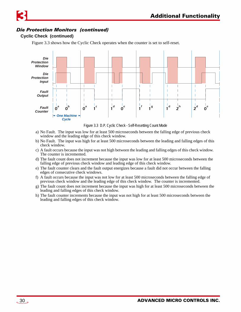
Figure 3.3 shows how the Cyclic Check operates when the counter is set to self-reset.
Figure 3.3 D.P. Cyclic Check - Self-Resetting Count Mode
a) No Fault. The input was low for at least 500 microseconds between the falling edge of previous check window and the leading edge of this check window.
b) No Fault. The input was high for at least 500 microseconds between the leading and falling edges of this check window.
c) A fault occurs because the input was not high between the leading and falling edges of this check window. The counter is incremented.
d) The fault count does not increment because the input was low for at least 500 microseconds between the falling edge of previous check window and leading edge of this check window.
e) The fault counter clears and the fault output energizes because a fault did not occur between the falling edges of consecutive check windows.
f) A fault occurs because the input was not low for at least 500 microseconds between the falling edge of previous check window and the leading edge of this check window. The counter is incremented.
g) The fault count does not increment because the input was high for at least 500 microseconds between the leading and falling edges of this check window.
h) The fault counter increments because the input was not high for at least 500 microseconds between the leading and falling edges of this check window.
One Machine Cycle
DieProtection
Window
DieProtection
Input
FaultOutput
FaultCounter
0a
0a
1d
1f
1d
2d
0b
1c
0e
1g
2h
0e
ADVANCED MICRO CONTROLS INC.30

Additional Functionality 3
Die Protection Monitors (continued)Constant Check
This mode uses the Check Windows associated with the input. The input must be active while the position is within the entire check window and must be inactive for at least 500 microseconds while outside of the win-dow. Errors that occur within a check window are reported immediately. Faults that occur outside of a check window are recognized at the leading edge of the check window. The fault count will only increment once between the falling edges of consecutive check windows.
Figure 3.4 shows how the Constant Check operates when the counter is set to continuously count.
Figure 3.4 Constant Check - Continuous Count Mode
a) No Fault. The input was low for at least 500 microseconds between the falling edge of previous check window and the leading edge of this check window.
b) No Fault. The input was high during the entire check window.c) A fault occurs because the input was not high during the entire check window.d) The fault count increments because the input was not low for at least 500 microseconds between the fall-
ing edge of previous check window and the leading edge of this check window.e) The fault count does not increment because the fault count will only increment once between falling edges
of consecutive check windows. The count incremented at (d).f) The fault count does not increment because the input was low for at least 500 microseconds between the
falling edge of previous check window and the leading edge of this check window.g) The fault count increments because the input goes low during the check window and this is the first fault
between the falling edges of consecutive check windows.
One Machine Cycle
DieProtection
Window
DieProtection
Input
FaultOutput
FaultCounter
0a
1c
2d
2f
0b
2e
3g
20 Gear Drive, Plymouth Ind. Park, Terryville, CT 06786Tel: (860) 585-1254 Fax: (860) 584-1973 http://www.amci.com
31

Additional Functionality3
Die Protection Monitors (continued)Constant Check (continued)
Figure 3.5 shows how the Constant Check operates when the counter is set to self-reset.
Figure 3.5 Constant Check - Self-Resetting Count Mode
a) No Fault. The input was low for at least 500 microseconds between the falling edge of previous check window and the leading edge of this check window.
b) No Fault. The input was high during the entire check window.c) A fault occurs because the input was not high during the entire check window.d) The fault count increments because the input was not low for at least 500 microseconds between the fall-
ing edge of previous check window and the leading edge of this check window.e) The fault count does not increment because the fault count will only increment once between the falling
edges of consecutive check windows. The count incremented at (d).f) The fault count does not increment because the input was low for at least 500 microseconds between the
falling edge of previous check window and the leading edge of this check window.g) The fault count resets to zero and fault output energizes because a fault did not occur between falling
edges of consecutive check windows.
One Machine Cycle
DieProtection
Window
DieProtection
Input
FaultOutput
FaultCounter
0a
1c
2d
2f
0b
2e
0g
ADVANCED MICRO CONTROLS INC.32

Additional Functionality 3
Die Protection Monitors (continued)Quick Check
This mode uses the Check Windows associated with the input. The input must be active for at least 500 microseconds while the position is within the window and must be inactive while outside of the window. If the input is never active within the Check Window, a fault will be issued, and the count incremented, at the falling edge of the Check Window. Faults outside of the Check Window are issued, and the count increments, as soon as the input is high. The fault count will only increment once between the falling edges of consecu-tive check windows.
Figure 3.6 shows how the Quick Check operates when the counter is set to continuously count.
Figure 3.6 Quick Check - Continuous Count Mode
a) No Fault. The input was low between the falling edge of previous check window and the leading edge of this check window.
b) No Fault. The input was high for at least 500 microseconds during this check window.c) A fault occurs because the input was not high for at least 500 microseconds during this check window.d) The fault count increments because the input goes high between check windows. The counter increments
here because the fault at (c) occurred because of the input’s state prior to the falling edge of the last check window.
e) Fault count increments on the falling edge of the check window because the input is high.
One Machine Cycle
DieProtection
Window
DieProtection
Input
FaultOutput
FaultCounter
0a
0a
2d
0b
1c
3e
20 Gear Drive, Plymouth Ind. Park, Terryville, CT 06786Tel: (860) 585-1254 Fax: (860) 584-1973 http://www.amci.com
33

Additional Functionality3
Die Protection Monitors (continued)Quick Check (continued)
Figure 3.7 shows how the Quick Check operates when the counter is set to self reset.
Figure 3.7 Quick Check - Self-Resetting Count Mode
a) No Fault. The input was low between the falling edge of previous check window and the leading edge of this check window.
b) No Fault. The input was high for at least 500 microseconds during this check window.c) A fault occurs because the input was not high for at least 500 microseconds during this check window.d) The fault count increments because the input goes high between check windows. The counter increments
here because the fault at (c) occurred due to the input’s state prior to the falling edge of the last check win-dow.
e) The pulse is missing in the check window, but the fault count does not increment because of the fault that occurred at (d). The fault count will only increment once between the falling edges of consecutive check windows.
f) The fault count does not increment because the input was low for the entire time between the falling edge of previous check window and the leading edge of this check window.
g) The fault count clears and fault output energizes because a fault did not occur between falling edges of consecutive check windows.
Production CountersA total of six counters are available on the ANS1.
Part Cycle Counter
This counter tracks the number of part cycles for the running program. This counter increments at the posi-tion set by the Production Cycle Increment Position parameter, which has a default of zero. This counter value is affected by the Production Cycle Multiplier and Production Cycle Divisor parameters. The value of this counter is:
Machine Revolutions * Production Cycle Multiplier / Production Cycle Divisor
Both the Production Cycle Multiplier and Divisor parameters have default values of one.
The Part Cycle Counter has a Counter Limit Value parameter associated with it. The Counter Limit Value parameter has a range of 0 to 999,999,999. Any one of the sixteen outputs can also be associated with this counter as the Counter Overflow Output. This output can be programmed to turn on when the programmed count limit is reached, toggle state when the limit is reached, or be enabled when the count equals the pro-grammed Counter Limit Value.
One Machine Cycle
DieProtection
Window
DieProtection
Input
FaultOutput
FaultCounter
0a
0a
2d
2f
0b
1c
2e
0g
ADVANCED MICRO CONTROLS INC.34

Additional Functionality 3
Production Counters (continued)Batch Counters 1, 2, 3
These counters track the number of part cycles for the running program. One output can be associated with each counter. The counter can be programmed to increment on each cycle, or only on cycles that do not have a die protection fault.
Each Batch Counter has a Counter Limit Value parameter associated with it. The Counter Limit Value param-eter has a range of 0 to 999,999,999. Any one of the sixteen outputs can also be associated with this counter as the Counter Overflow Output. This output can be programmed to turn on when the programmed count limit is reached, toggle state when the limit is reached, or be enabled when the count equals the programmed Counter Limit Value.
Good Part Counter
In press applications, the die protection functionality of the ANS1 allows you to determine when a bad part has been made. The Good Part Counter is equivalent to the Part Cycle Counter, but only increments when a die protection fault did not occur during the cycle.
This counter is a free running counter. It does not have a programmable limit value and an output cannot be associated with it.
Machine Revolutions
This counter tracks the number of revolutions the machine has made while running the active program. It increments as the position passed through zero. This value can be preset to any value in its range and is stored in non-volatile memory with the program’s parameters.
This counter is a free running counter. It does not have a programmable limit value and an output cannot be associated with it.
Using Batch Counter Outputs
As stated above, the three batch counters, and the Part Cycle Counter, each have a Counter Limit Value parameter associated with the counter. Additionally, any of the sixteen outputs can also be associated with a counter as its Counter Overflow Output.
How the output reacts to the counter reaching its programmed Counter Overflow Output value depends on any additional limit switch programming that may exist on the output.
If no additional limit switch programming data exists for the output, the output can be programmed to be active when the counter value equals the programmed Counter Overflow Output value or change state when the counter value equals the programmed Counter Overflow Output value.
If the output has limit switch programming data associated with it, (one or more setpoint pairs and or programming for a timed output), then the output is enabled whenever the counter value equals the pro-grammed Counter Overflow Output value. The output will follow its programmed setpoints only when the counter value equals the programmed Counter Overflow Output value.
20 Gear Drive, Plymouth Ind. Park, Terryville, CT 06786Tel: (860) 585-1254 Fax: (860) 584-1973 http://www.amci.com
35

Additional Functionality3
NotesADVANCED MICRO CONTROLS INC.36

20 Gear Drive, Plymouth IndTel: (860) 585-1254 Fax: (8
CHAPTER 4
INSTALLING THE ANS1Module Installation
Module Location
AnyNET-I/O modules are suitable for use in industrial environments that meet the following criteria:
Only non-conductive pollutants normally exist in the environment, but an occasional temporary con-ductivity caused by condensation is expected.
Transient voltages are controlled and do not exceed the impulse voltage capability of the product’s insu-lation.
Note that these criteria apply to the system as a whole. These criteria are equivalent to the Pollution Degree 2 and Over Voltage Category II designations of the International Electrotechnical Commission (IEC).
Safe Handling Guidelines
Prevent Electrostatic Damage
Electrostatic discharge can damage an AnyNET-I/O module if you touch the rear bus con-nector pins. Follow these guidelines when handling the module.
1) Touch a grounded object to discharge static potential before handling the module.2) Work in a static-safe environment whenever possible.3) Wear an approved wrist-strap grounding device.4) Do not touch the pins of the bus connector or I/O connector.5) Do not disassemble the module6) Store the module in its anti-static bag and shipping box when it is not in use.
Prevent Debris From Entering the Module
During DIN rail mounting of all devices, be sure that all debris (metal chips, wire strands, tapping liquids, etc.) is prevented from falling into the module. Debris may cause damage to the module or unintended machine operation with possible personal injury. The DIN rail for the modules should be securely installed and grounded before the modules are mounted on it.
Remove Power Before Servicing in a Hazardous Environment
Remove power before removing or installing any modules in a hazardous environment.
. Park, Terryville, CT 0678660) 584-1973 http://www.amci.com
37

Installing the ANS14
Module Installation (continued)Module Mounting
Dimensions
Below is an outline drawing compatible with the ANS1 module.
Figure 4.1 ANS1 Outline Drawing
Compatible DIN Rail
The ANS1 along with an RB-7 or RB-8 relay board can be mounted on following DIN rail:
EN 05 022 - 35 x 7.5 (35 x 7.5 mm)
If you are only installing one ANS1 module instead of an interconnected stack, then you can also use the fol-lowing DIN rail:
EN 05 022 - 35 x 15 (35 x 15 mm)
The EN 05 022 - 35 x 15 DIN rail is unacceptable when installing multiple AnyNET-I/O mod-ules as a stack. The IC-5 connector that is used to interconnect the modules requires the EN 05 022 - 35 x 7.5 DIN rail for proper operation.
The DIN Rail must be securely mounted to a panel and solidly grounded before the module is installed. Grounding is usually accomplished through the mounting hardware, by first removing any paint or other material from all surfaces that may interfere with proper grounding. Another option is to install a heavy gauge wire from the DIN rail to your system’s ground bus.
4.47"(113.5)
5.10"(129.5)
3.9
0"
(99.
1) 4.5
5"
(115
.6)
1.78" (45.2)
I/O Mating Connector
0.26"(6.6)
ADDRESS
PLS
PWR FUSE
IN OUT
09 0913 13
10 1014 14
11 1115 15
12 1216 16
ADDRESS
PLS
PWR FUSE
IN OUT
09 0913 13
10 1014 14
11 1115 15
12 1216 16
ADVANCED MICRO CONTROLS INC.38

Installing the ANS1 4
Module Installation (continued)Module Mounting (continued)
Installing IC-5 Connectors
IC-5 connectors must be used when more than one module is installed as an interconnected stack. The ANS1 uses two IC-5 connectors. Fig-ure 4.2 shows how to install the IC-5 connectors in the DIN rail.
1) EN 05 022 - 35 x 7.5 DIN rail must be used. The IC-5 connec-tors are not properly supported in EN 05 022 - 35 x 15 DIN rail
2) Note the orientation of the IC-5 connectors when installing them.The module key goes towards the bottom of the DIN rail.
Mounting the AnyNET-I/O Module
Mounting an AnyNET-I/O module is a very simple process thanks to the design of the enclosure.
1) Partially engage the connector into the enclosure.
2) Engage the top clip in the enclosure with the top of the DIN rail and rotate the module down until the metal bracket snaps on to the DIN Rail.
Once all of your modules are installed, it is strongly suggested to use the end caps from Phoenix Contact with the part number of 271 37 80 to secure the modules on the DIN Rail. These end caps prevent the module from sliding along the DIN rail if it is subjected to shock or vibration during machine operation.
Stack Addressing
Each module is a stack needs to be given an address before the system will operate correctly. The address is set with the five position DIP switch on the front of the module.
1) The module with the network interface for the stack must have all of its DIP switches off. (This is called address 0.) This is the only module in the stack that can have a direct network connection.
2) Only a single switch should be in the “ON” position when setting the address.
3) If a module has a network interface, this interface is disabled if the module has a non-zero address. This allows two mod-ules with network interfaces to work in a single stack.
Figure 4.3 is a close up of three modules in an AnyNET-I/O Stack. The module on the left is an unit with a network interface, and has an address of zero (All DIP switches off.) This module has the active network interface and connects the stack to the network. Reading left to right, the remaining modules have addresses of one and two respectively. These modules can be any type of AnyNET-I/O modules. If they have network interfaces, these interfaces are disabled.
Figure 4.2 IC-5 Connector Installation
Figure 4.3 Addressing Example
AD
DR
ESS
AD
DR
ESS
AD
DR
ESS
Address=0
Address=1
Address=2
20 Gear Drive, Plymouth Ind. Park, Terryville, CT 06786Tel: (860) 585-1254 Fax: (860) 584-1973 http://www.amci.com
39

Installing the ANS14
Powering the ModuleRequired Power
The ANS1 requires 12 to 24 Vdc ± 20% supply to power the module. Surges to 30Vdc will not damage it. Current draw is 225 mA @ 24Vdc (5.4W).
This current draw does not include current through the inputs or outputs. If using the same supply to power the I/O, their load must be considered when sizing the supply.
Inputs require 10mA each. Outputs on the ANS1 can supply up to 1 Adc each. Relay outputs on the RB-7 or RB-8 can supply up to 3 Adc when the KD-6 relays are used.
Wiring
As shown in the figure below, the power connector is located on the bottom of the module. The mating con-nector is included with the ANS1. Spares are available from AMCI under the part number MS-4M. They are also available from Phoenix Contact under their part number 187 80 37.
Figure 4.4 Power Connector Location
Power connections should be tight, as loose connections may lead to arcing which will heat the connector. Phoenix Contact specifies a tightening torque of 4.4 to 5.4 lb-in (0.5 to 0.6 Nm).
The power supply is connected to the pins marked “+Vdc In” and “DC Return”. The “Chassis GND” pin is used to attach the ANS1 to earth ground.
1) AnyNET-I/O modules are electrically isolated from the DIN rail by their mounting, but the Chassis GND connection is common to all of the modules in the stack through a pin of the IC-5 connector. At least one module in the AnyNET-I/O Stack must be attached to earth ground through a heavy gauge stranded wire to ensure reliable operation of the stack.
2) Each ANS1 module must have its own power connection.
3) AnyNET-I/O modules will not be damaged if it is plugged into the InterConnect bus while power is applied, but the stack will not reconfigure itself to accept the new module.
Transducer Installation
AMCI Engineering Data Download Location
The ANS1 is compatible with many of the resolver based transducer products available from AMCI. A list of compatible transducers can be found in the Compatible AMCI Transducers section of the Introduction chap-ter, starting on page 13.
Outline drawings and specification sheets for all compatible transducers are available on our website at: www.amci.com/resolvers.asp. Specification sheets include connector pinout information.
Power Connector
ANS1 Bottom View +Vdc
DC Return
Chasis GND (Shields)
DC Return
Area forNetwork
Connections*
ADVANCED MICRO CONTROLS INC.40

Installing the ANS1 4
Transducer Installation (continued)AMCI Transducer Mounting Guidelines
All AMCI resolver transducers are designed for industrial environments and therefore require little attention. The resolver is electrically isolated from the body of the transducer to eliminate the potential for ground loops and ground shifts in the system. The main guideline to follow when mounting the transducers is to limit bear-ing loads when coupling the transducer to your machine. This includes using flexible couplers when directly coupling shafts to eliminate shaft misalignments.
The following bearing load ratings are known as “L10 ratings” in the bearing trade associations. L10 is a stat-ical rating meaning that 90% of the bearings will survive the specified number of revolutions. AMCI speci-fies our rated number of revolutions as 2X10⁹, or 2 billion, which is a number commonly used in the industry. By specifying the maximum load and statical life, AMCI gives you data you need to choose the right trans-ducer for your application.
Note that these load ratings are maximums, and you should always strive to keep shaft loading to a minimum. The inverse relationship between shaft loading and bearing life is not linear, it's exponential.
This means that decreasing the shaft loading by half will, statically, increase the bearing life by a factor of eight. For example, decreasing a shaft load from 100 lbs. to 50 lbs. yields: [100/50]3 = 8 times increase in sta-tistical bearing life.
At the loads specified below, bearing life is a minimum of 2x10⁹ revolutions. Note that the R11 series and HT-6 transducers always require a flexible coupler to your machine because of their shaft sizes.
Transducer Cabling
Suggested Cable
For cable lengths less than 100 feet, AMCI suggests Belden 9873 or an equivalent cable. For cable lengths of 100 feet and greater, AMCI suggests Belden 9730 or an equivalent cable. Note that Belden 9730 can also be used for cable lengths less than 100 feet.
Shaft Dia. Maximum Radial Load
Maximum Axial Load
R11X and R15X Series0.120" 2.0 lbs. (8.9N) 1.0 lb. (4.4N)0.188" 6.0 lbs. (26.7N) 3.0 lbs. (13.3N)
HT-60.188" 6.0 lbs. (26.7N) 3.0 lbs. (13.3N)
H25 Series0.250" 40 lbs. (178N) 20 lbs. (89N)10 mm 40 lbs. (178N) 20 lbs. (89N)0.375" 40 lbs. (178N) 20 lbs. (89N)0.625" 100 lbs. (445N) 50 lbs. (222N)
HT Series0.375" 100 lbs. (445N) 50 lbs. (222N)0.625" 100 lbs. (445N) 50 lbs. (222N)
1x---
3where x
new shaft loadold shaft load----------------------------------- old shaft load
new shaft load-----------------------------------
3=
20 Gear Drive, Plymouth Ind. Park, Terryville, CT 06786Tel: (860) 585-1254 Fax: (860) 584-1973 http://www.amci.com
41

Installing the ANS14
Transducer Cabling (continued)Installation Guidelines
In the United States, the National Electrical Code cable type used for the transducer cable is CM (Communications, General Purpose cable). Therefore the installation of the cable falls under Article 800 of the National Electrical Code and must be followed. Note that this does not preclude the possibility that your local code or company policy is more restrictive.
The shields of the transducer cable must be grounded at the ANS1 only! The Shield pin on the Transducer Input Connector is brought to the chassis pin on the power supply connector.
When installing the cable, treat the shield as a signal carrying conductor. If you must splice the cable, it must be done in a junction box. Follow these guidelines:
Do not strip the shield back any further than needed to make the splice. Do not connect the shield to ground at any junction box or the transducer. This will eliminate ground
loops that could damage the ANS1 and prevent ground shifts from damaging the cable or controller.
Single Resolver Transducers
Pre-assembled and tested transducer cables can be purchased for most of the AMCI transducers that are com-patible with the ANS1. The part number for the cable is CTL-(x), where (x) is the length in feet. The follow-ing diagram shows how to wire a standard AMCI single resolver transducer to the ANS1.
Figure 4.5 AMCI CTL Cable Wiring
1) There are two ways to reverse the count direction when using single resolver transducers. One method is to set the Count Direction parameter when programming the ANS1. The other method is to reverse the connections on one of the stator pairs. AMCI standard method is to reverse the S2-S4 pair, which is the green/black pair of the CTL cables.
2) When using a foreign single resolver transducer, note how the signals are paired in the cable and use this pairing when generating your wiring diagrams.
3) The cable shields must be isolated from earth ground at the transducer to prevent ground loops and ground shifts. When using a foreign transducer, do not attach the shields to a transducer pin, even if this follows the standard of your transducer’s manufacturer.
11109
87654321
11109
87654321
R1S4S1, S2
R2S3
ShieldGRNBLKBLKWHTREDBLK
BELDEN 9873 Cable or exact equ.For cable lengths greater than100' (30 meters) use BELDEN 9730.
TransducerConnectorAMCI Part #: MS-16Bendix #: MS3106A16S-1S
A B
E
G
ANS1 TOP VIEW(Left Connector Only)
J2J1
ADVANCED MICRO CONTROLS INC.42

Installing the ANS1 4
Transducer Wiring (continued)Single Resolvers
Figure 4.6 shows the connections required to attach a resolver with industry standard wire colors to a Belden 9873 or 9730 cable. If these connections are followed, you can refer to figure 4.5 on page 42 for connections from the Belden cable to the ANS1.
Figure 4.6 Resolver to Cable Connections
Foreign TransducersPopular transducers from other manufacturers can be used with the ANS1. The resolver must have the fol-lowing characteristics:
Control Transmitter (Rotor as the primary) Operating frequency between 2.2 KHz and 7 KHz Transformation Ratio (TR) between 0.9 and 1.0
If the resolver does not have a TR between 0.9 and 1.0, a Reference Module from AMCI is required to make the resolver compatible with the ANS1. The Reference Module is a single ended transformer that either raises or lowers the reference voltage going out to the resolver so that the return signals are in the proper range for the ANS1. The following table lists the Reference Modules available from AMCI, the TR of the resolvers they are designed for, and the manufacturers that typically use these resolvers.
† Some manufacturers, including AMCI, allow you to specify the resolver used in the transducer. Verify all transducer part numbers with the manufacturer before ordering an AMCI reference module.
Table 4.1 Available Reference Modules
Additional Information on AMCI Reference Modules can be downloaded from our website at: http://www.amci.com/pdfs/accessories/RM_wiring.pdf
Regardless of the type of cable suggested by the transducer manufacturer, AMCI strongly rec-ommends Belden 9873, 9730, or exact equivalents as cables for your transducer. With tens of thousands of installations worldwide, AMCI is confident in the quality of these cables. If you wish to use a different cable, contact AMCI to verify your cable type.
Part Number Resolver TR Manufacturer†
RM-1 0.50 Namco/C&A Products
RM-3 1.40 Gemco, Autotech
RM-5 0.45 Electro Cam
RED S1
BLK S3
BLK / WHT*
A yellow wire with a white tracer is sometimes used instead of a black wire with a white tracer.All AMCI resolvers use a black/white wire.
R2
RED / WHT R1
WHT
BLK
Shields of the cable must not be connected to chassis ground except at the module.Strip the shields back to inside the cable.
GRN
BLKBELDEN9873 or
9730 Cable
RED
BLK
BLU S4
YEL S2 *
20 Gear Drive, Plymouth Ind. Park, Terryville, CT 06786Tel: (860) 585-1254 Fax: (860) 584-1973 http://www.amci.com
43

Installing the ANS14
Quadrature Encoder InstallationThe ANS1 also supports quadrature encoders for position monitoring. The module is designed to accept dif-ferential inputs, but can be wired to accept single ended sinking or sourcing encoders.
By default, the ANS1 is configured to output quadrature signals. These pins can be used as quadrature signal inputs when the Quad Direction pin is tied to ground. If this pin is not tied to ground when power is applied to the module, the ANS1, your quadrature encoder, or both, may be damaged.
The resolver signals are ignored when the Quad Direction pin is tied to ground.
AMCI Compatible Encoders
AMCI has a complete line of resolver based transducers with quadrature outputs. Additional information on these encoders can be found here:
http://www.amci.com/rotary-encoders/incremental-rotary-encoder.asp
Differential Wiring
The figure below shows how to wire a 5Vdc differential encoder to the ANS1.
Figure 4.7 Sample Differential Encoder Wiring
+Pwr–Pwr Shield–Z+Z–B
+B–A+A
Quadrature Encoder withDifferential Outputs
REDBLK
ShieldBLKBLUBLK
GRNBLK
WHT
REDBLK
BLKBLUBLK
GRNBLK
WHT
–Z+Z–B+B–A+A
+Z+B+AGND
–Z–B–A
QuadDir
+5Vdc IsolatedPower Supply
Belden 8304 or equ. Suggested
1110987654321
1110987654321
ANS1 TOP VIEW(Left Connector Only)
J2J1
ADVANCED MICRO CONTROLS INC.44

Installing the ANS1 4
Encoder Wiring (continued)Single Ended Wiring
Figure 4.8 below shows how to wire the encoder inputs to both a single ended sourcing and single ended sink-ing encoder outputs.
The encoder inputs on the ANG1 are rated for 5Vdc only. You must use a current limit-ing resistor on each input if the outputs of your encoder are greater than 5Vdc. Appro-priate current limiting resistors are shown in the figure below.
Figure 4.8 Single Ended Encoder Wiring
Relay Board InstallationAMCI offers the RB-7 and RB-8 relay boards for connecting outputs 1 through 8 to the outside world.
The RB-7 offers eight solid-state relay outputs The RB-8 offers eight solid-state relay outputs and eight opto-isolated DC inputs
ANS1 Encoder Input Connection to Sourcing Encoder Output
ANS1 Encoder Input Connection to Sinking Encoder Output
RLIM
RLIM
OUT
OUT
–
–
Supply RLIM
5 Vdc None
12 Vdc 2.0 Kohm
15 Vdc 2.4 Kohm
24 Vdc 4.7 Kohm
+
+
–
–
20 Gear Drive, Plymouth Ind. Park, Terryville, CT 06786Tel: (860) 585-1254 Fax: (860) 584-1973 http://www.amci.com
45

Installing the ANS14
Relay Board Installation (continued)DIN Rail / Panel Mount Conversion
The relay boards can be DIN rail or panel mounted and require a +24Vdc supply for operation. They are shipped from AMCI in their DIN rail mount configuration and can be mounted on EN 50 022 or EN 50 035 channel. The procedure for converting them to panel mount is given below.
Figure 4.9 Panel Mount / DIN Rail Conversion
RB-7 Outline Drawing
Figure 4.10 RB-7 Outline Drawing
1) Remove the two hex head screws that hold the panel mount bracket in place.
2) Remove the DIN rail adapter bracket.
3) Reverse the panel mount bracket and re-install it with the two hex head screws.
4) Repeat on the other side.
Panel Mount Bracket
DIN Rail Adapter Bracket
Hex head Screw
BOTTOM VIEW OF RELAY BOARD(INCOMPLETE)
U U U U U U UU
K1 K2 K3 K4 K5 K6 K7 K8U
FUSETESTER
DS1
F1SPARE FUSE
FROMMODULE
CN1
+ + + +4/12 +5/13 +6/14 +7/15 +8/16 COM +24VGND
E1
8.25 in
2.25" max.(57.2)
2.85" max.(72.4)
2.50" typ.(63.5)
1.77" typ.(45.0)
3.80"(96.5)
0.65" (16.5) typ.7.999 in 8.00" (203.2) Suggested Mounting Dimension
7.7" (196) typical dimension with brackets reversed)
1/9 2/10 3/11
ADVANCED MICRO CONTROLS INC.46

Installing the ANS1 4
Relay Board Installation (continued)RB-8 Outline Drawing
Figure 4.11 RB-8 Outline Drawing
Compatible Relays
Every output requires a solid state relay. The RB-7 and RB-8 are designed for OPTO 22 Generation 4 style relays. There relays are fused protected, and have a retaining screw and indicator LED. AC and DC relays are available from AMCI under the following part numbers.
Figure 4.12 Compatible Relays
AMCI Part # Opto 22 Part # WRC Part# Output Voltage Rated Current
KD-6 G4ODC24 WRC4-OBXS11 3 to 60 Vdc 3 Adc
KA-3 G4OAC24 WRC4-OAXS 120 Vac 3 Aac
U U U U U U UU
K1 K2 K3 K4 K5 K6 K7 K8U
FUSETESTER
DS1
F1SPARE FUSE
FROMMODULE
CN1
+ + + +4/12
+5/13
+6/14
+7/15
+8/16 COM +24V
GND E1
8.25 in
2.25" max.(57.2)
2.85" max.(72.4)
2.50" typ.(63.5)
1.77" typ.(45.0)
3.80"(96.5)
0.65" (16.5) typ.7.999 in 8.00" (203.2) Suggested Mounting Dimension
7.7" (196) typical dimension with brackets reversed)
1/9 2/10 3/11
COM
E2
20 Gear Drive, Plymouth Ind. Park, Terryville, CT 06786Tel: (860) 585-1254 Fax: (860) 584-1973 http://www.amci.com
47

Installing the ANS14
Relay Board Installation (continued)Connections to the ANS1
The interconnection between the ANS1 and the relay board is made with a CRP-(x) cable, where (x) is the cable’s length in feet. Presently, two, six, and twelve foot cables are available from AMCI. CRP cables are shielded, fine pitch ribbon cables with drain lugs at both ends. Due to their complexity, AMCI strongly rec-ommends that you purchase pre-assembled and tested CRP cables instead of making them yourself.
Connections are made by inserting the blue IDC connector into the proper socket and connecting the drain wire to the screw terminal. Note that the IDC connector is keyed and can only be inserted in one way. The retaining clips on the IDC socket snap over the top of the connector to secure it in place. The drain wire on the CRP cable must be connected to the screw terminals next to the IDC sockets. The screw terminal on the ANS1 is connected to Earth Ground pin on its power connector. The screw terminals on the relay boards are connected to the “CHASSIS GND” pin on the power connector.
Figure 4.13 CRP-(x) Installation
The RB-8 has two IDC connectors. When attaching the RB-8 to an ANS1, the CN1 connector must be used. The CN2 connector is an expansion connector that allows you to daisy-chain two relay boards together. This connector is not used in ANS1 installations.
Powering the RB Boards
An external +24Vdc supply is needed to drive the inputs and relays. Connection to the relay boards is shown below along with maximum current draw. Note that these measurements are from the relay boards only. If you are using an RB-8 and powering the input sensors with the same supply, then you must add in the current requirements of each sensor to determine the power supply size.
When a relay board is DIN rail mounted the case is isolated from the panel by the plastic DIN rail adapters. You MUST run a heavy gauge wire from the Chassis GND terminal of the power supply terminal block to your ground bus to ground the metal relay board case. When a relay board is panel mounted the case is usually connected to chassis ground through the mounting hardware. If you believe that the ground is insufficient then run a heavy gauge wire from the Chassis GND terminal to your ground bus.
ADDRESS
PLSCN1
CRP-(X) Cable
COM +24VGND RB-7: 100 mA Max.
RB-8: 125 mA Max.
Figure 4.14 Power Supply Connections
ADVANCED MICRO CONTROLS INC.48

Installing the ANS1 4
I/O WiringRelay Board Inputs
The RB-8 relay board has a terminal block that allows you to connect to inputs 1 through 8 on the ANS1. All eight inputs are Sourcing Inputs. The Common pin on the terminal block must be attached to the positive lead of the power supply that is used to power the sensors. Figure 4.15 below shows how to wire sinking and sourcing sensors to the RB-8 relay board inputs.
Figure 4.15 Wiring RB-8 Inputs
Relay Board Outputs
Outputs on the RB-7 and RB-8 can be wired as either sinking or sourcing outputs. When wiring to DC relays, the “+” terminal must be attached to the higher side of the load.
COM
COM
DC Sinking Sensors
DC Sourcing Sensors
+12 Vdc to +24 VdcIsolated Power SupplyCan use thesame supply to power all inputs
+12 Vdc to +24 VdcIsolated Power SupplyCan use thesame supply to power all inputs
–
RPD
Supply RPD
12 Vdc 600 to 660 ohm
15 to 24 Vdc 1.74 to 1.80 Kohm
–
20 Gear Drive, Plymouth Ind. Park, Terryville, CT 06786Tel: (860) 585-1254 Fax: (860) 584-1973 http://www.amci.com
49

Installing the ANS14
I/O Wiring (continued)ANS1 Inputs
The ANS1 has terminal block connections for inputs 9 through 16 on the ANS1. All eight inputs are Sinking Inputs. The Common pin on the terminal block must be attached to the negative lead of the power supply used to power the sensors. Figure 4.16 below shows how to wire sourcing and sinking sensors to the ANS1 inputs.
Figure 4.16 Wiring ANS1 Inputs
DC Sourcing Sensors
DC Sinking Sensors
+12 Vdc to +24 VdcIsolated Power SupplyCan use thesame supply to power all inputs
+12 Vdc to +24 VdcIsolated Power SupplyCan use thesame supply to power all inputs
–
–
RPU
Supply RPU
12 Vdc 600 to 660 ohm
15+ Vdc 1.74 to 1.80 Kohm
1110987654321
1110987654321
1110987654321
1110987654321
ANS1 TOP VIEWRight Connector Only
(Above Indicator LED’s)
ANS1 TOP VIEWRight Connector Only
(Above Indicator LED’s)
J4
J4
J3
J3
Not UsedCommon+Vdc InOut 9Out 10Out 11Out 12Out 13Out 14Out 15Out 16
Not UsedCommon+Vdc InOut 9Out 10Out 11Out 12Out 13Out 14Out 15Out 16
Not UsedShieldNot UsedIn 9In 10In 11In 12In 13In 14In 15In 16
Not UsedShieldNot UsedIn 9In 10In 11In 12In 13In 14In 15In 16
ADVANCED MICRO CONTROLS INC.50

Installing the ANS1 4
I/O Wiring (continued)ANSI Outputs
The ANS1 has outputs 9 through 16 available on the I/O connector. These are 12 to 24Vdc sourcing outputs. All eight outputs share the single power supply, which must be connected to the “+Vdc In” pin shown in fig-ure 4.17 below.
Figure 4.17 ANS1 Output Wiring
1) The “+Vdc In” pin carries the current for all of the outputs. The connector is rated for a max-imum of eight amps per pin, and a 16 AWG wire should be used to connect this pin to the power supply.
2) Overloading any of the outputs will trip the internal resettable fuse, which will temporarily disable all eight outputs.
3) All inductive loads must have surge suppression devices installed on their input terminals. Repeated high voltage spikes on the outputs of the ANS1 may permanently damage them.
+12 Vdc to +24 VdcPower Supply
DC Load
DC Load
1110987654321
1110987654321
ANS1 TOP VIEWRight Connector Only
(Above Indicator LED’s)
J2J1Not UsedCommon+Vdc InOut 9Out 10Out 11Out 12Out 13Out 14Out 15Out 16
Not UsedShieldNot UsedIn 9In 10In 11In 12In 13In 14In 15In 16
16 AWG Wire
All DC inductive loads musthave surge suppression devicesinstalled on their input terminals
20 Gear Drive, Plymouth Ind. Park, Terryville, CT 06786Tel: (860) 585-1254 Fax: (860) 584-1973 http://www.amci.com
51

Installing the ANS14
I/O Wiring (continued)Encoder Output Wiring
Figure 4.18 below shows how to connect the encoder outputs from an ANS1 to a slave device that requires quadrature encoder inputs.
Figure 4.18 ANS1 Slave Module Connections
Slave Module Wiring
Figure 4.19 below shows how to slave multiple ANS1 modules together for applications that require more than sixteen I/O points.
Figure 4.19 ANS1 Slave Module Connections
Programming Web InterfaceConnection to the custom web server on the ANS1 is made through the RJ45 connector on the main (left) board. See figure 4.4 on page 40 for the location of the connector. Connection is made with a standard Ether-net cable to a computer, laptop, or industrial PC. The ANS1 contains an auto-sensing port, so a crossover cable is not required when directly connecting a computer to the ANS1. The default address of the Web Inter-face is http://192.168.0.40/index.htm. The address can be changed
–Z+Z–B+B–A+A
BLKREDBLK
GRNBLK
WHT
BLKREDBLK
GRNBLK
WHT
–Z+Z–B+B–A+A
+Z+B+A
SHLD–Z–B–A
QuadDir
Belden 8303, 9730, or equ. Suggested1110987654321
1110987654321
ANS1 TOP VIEW(Left Connector Only)
J2J1
J4 J4 J4J3 J3 J31110
987654321
J2 J2 J2J1 J1 J1
+TxD +RxD +TxD +RxD
–TxD –RxD –TxD –RxD
(3) ANS1 Modules in an AnyNET-I/O Stack
ADVANCED MICRO CONTROLS INC.52

20 Gear Drive, Plymouth IndTel: (860) 585-1254 Fax: (8
CHAPTER 5
OUTPUT DATA FORMATCommand WordThe first word of the data transfer is the Command Word. The bit pattern in this word defines the program-ming data in the remaining output words as well as the data that should be returned to the host controller. As shown in the figure below, the bottom four bits of this word defines the command block.
Figure 5.1 Command Word Format
Bit 15: Transmit Bit - The ANS1 will not act on data written to the module until this bit makes a 01 transi-tion. On a 01 transition of the Transmit Bit, the ANS1 will decode and act upon the command block, write the appropriate response to the input data, and set the Acknowledge Bit in the input data. This Transmit/Acknowledge handshaking protocol is used because some hosts will send data to the ANS1 on a periodic basis instead of only when a change is needed.
Bits 14 - 5: The use of these bits changes based on the command block that is written to the ANS1. Generally, these bits are used to tell the ANS1 what programming data should be used in the remaining words of the block.
Bit 4: Clear Errors - This bit is used to clear programming and hardware errors in the ANS1.
Bits 3 - 0: Command Block - These bits define the data in the block. Their use is described below.
Command Block 0: Clear Errors OnlyThis block allows you to clear hardware errors, such as latched resolver transducer faults, and/or program-ming errors, without taking any other action. Bits 14 through 5 in the Command Word are ignored as are the remaining nineteen data words in the block.
Figure 5.2 Command Block 0
This chapter covers the format of the output data used to program and command the ANS1.
EtherNet/IPAddress
ModbusAddress
Bit Number
15 14 13 12 11 10 9 8 7 6 5 4 3 2 1 0
0 1024
Tra
nsm
it B
it
Use Depends on the Command Block
Cle
ar E
rror
Command Block Bits
EtherNet/IPAddress
ModbusAddress
Bit Number
15 14 13 12 11 10 9 8 7 6 5 4 3 2 1 0
0 1024
Tra
nsm
it B
it
0 0 0 0 0 0 0 0 0 0
Cle
ar E
rror
0 0 0 0
. Park, Terryville, CT 0678660) 584-1973 http://www.amci.com
53

Output Data Format5
Command Block 1: Define Return Data and I/O ForcesThis block allows you to define the data sent from the ANS1 to the host. Machine state and programmed parameter values can be returned. This block also allows you to force inputs and outputs on or off, which allows you to use ANS1 outputs as general purpose outputs.
Figure 5.3 Command Block 1
Command Word Bits
Bit 8: Apply Words 1-3. When this bit is set to ‘1’, set the Input Data to the attribute and I/O points defined in words 1, 2, and 3. When this bit is reset to ‘0’, ignore the data in words 1 through 3 and continue to report the present attribute in the Input Data.
Bit 9: Apply Words 4&5. When this bit is set to ‘1’, force the outputs on or off based on the bit pattern in words 4 and 5. When this bit is reset to ‘0’, keep the present output force states. The use of the out-put force words is described below.
Bit 10: Apply Words 6&7. When this bit is set to ‘1’, force the inputs on or off based on the bit pattern in words 6 and 7. When this bit is reset to ‘0’, keep the present input force states. The use of the input force words is described below.
EtherNet/IPAddress
ModbusAddress
Bit Number
15 14 13 12 11 10 9 8 7 6 5 4 3 2 1 0
0 1024T
rans
mit
Bit
0 0 0 0
App
ly W
ord
6,7
App
ly W
ord
4,5
App
ly W
ords
1-3
0 0 0
Cle
ar E
rror
0 0 0 1
1 1025 Return Data Attribute Number
2 1026 Output Point Number
3 1027 Input Point Number
4 1028 Output Force Enable Bits
5 1029 Output Forced State Bits
6 1030 Input Force Enable Bits
7 1031 Input Forced State Bits
8-19 1032-1043 Words not used by this Command Block
ADVANCED MICRO CONTROLS INC.54

Output Data Format 5
Command Block 1: Define Return Data and I/O Forces (continued)Return Data Attribute Number
Table 5.1 Return Data Attribute Number Listing
Output Force Words
Bit 15 through bit 0 of words 4 and 5 correspond to outputs 16 through 1. As shown in the truth table below, when a bit in word 4 equals ‘1’, the state of the associated output is set to the value of the bit in word 5.
Input Force Words
Bit 15 through bit 0 of words 6 and 7 correspond to inputs 16 through 1. As shown in the truth table below, when a bit in word 6 equals ‘1’, the state of the associated input is set to the value of the bit in word 7.
Table 5.2 Input Force Truth Table
Word 1 Value Returned Attribute Additional Parameter Format
Definition
0 Global Setup Data page 75
1 LS Setpoint Programming Requested LS Output number in word 2 page 76
2 LS Output Adjustment Programming Requested LS Output number in word 2 page 77
3 LS Enable Programming Requested LS Output number in word 2 page 78
4 Die Monitor Programming Requested Die Monitor Input in word 3 page 79
5 Brake Monitor Programming Requested Brake Monitor Input in word 3 page 80
6 Shift Register Programming page 81
7 Production Cycle Programming page 81
8 Counting Modes Programming page 82
16 Machine Status Data Additional data for Output defined in word 2 Additional data for Input defined in word 3 page 83
17 Counter Values page 85
18 Die Monitor States Additional data for Input defined in word 3 page 86
19 Brake Monitor and Output Advances States
Additional data for Output defined in word 2 Additional data for Input defined in word 3 page 87
20 Shift Register State page 88
Word 4 bit ‘n’(Enable)
Word 5 bit ‘n’(State) Output State
0 Don’t Care Determined by programming and machine state.
1 0 Off
1 1 On
Word 4 bit ‘n’(Enable)
Word 5 bit ‘n’(State) Input State
0 Don’t Care Determined by programming and machine state.
1 0 Off
1 1 On
20 Gear Drive, Plymouth Ind. Park, Terryville, CT 06786Tel: (860) 585-1254 Fax: (860) 584-1973 http://www.amci.com
55

Output Data Format5
Command Block 2: Global Machine ConfigurationThis block allows you to setup the position sensor used by the ANS1.
Figure 5.4 Command Block 2
Command Word Bits
Bit 14: Apply Machine Preset. When this bit is set to ‘1’, the Global Machine Position will be set to pro-grammed Machine Preset Value. The Machine Preset Value has a default value of zero. If bit 11 of the command word is also set to ‘1’, the Global Machine Position will be set to the value in word 5 of this block. When this bit is reset to ‘0’ the Global Machine Position will not be changed.
Bits 13 - 7: When one of these bits is set to ‘1’, program the parameter to the value in the associated word. When the bit is reset to ‘0’, leave the parameter at it last programmed value.
Bit 5: Restore Factory Defaults. When this bit is set to ‘1’, the ANS1 is reset to its factory default settings. This will restore all parameters to their default settings and erase all stored programming data.
Use this bit with caution. All programming is erased when this bit is set and parameters are restored to their factory default settings. Once erased, all programmed settings are lost and cannot be restored. Once reset to factory defaults, the ANS1 must be reprogrammed with new parameter values.
EtherNet/IPAddress
ModbusAddress
Bit Number
15 14 13 12 11 10 9 8 7 6 5 4 3 2 1 0
0 1024T
rans
mit
Bit
App
ly M
achi
ne P
rese
t
App
ly W
ord
8
App
ly W
ord
7
App
ly W
ords
5&
6
App
ly W
ord
4
App
ly W
ord
3
App
ly W
ord
2
App
ly W
ord
1
0
Res
tore
Fac
tory
Def
ault
s
Cle
ar E
rror
0 0 1 0
1 1025 Global Machine Bit Parameters
2 1026 Counts per Cycle (2 to 4,096)
3 1027 Full Scale Count (1 to Counts per Cycle)
4 1028 Scaled Machine Offset (-(Full Scale Count-1) to +(Full Scale Count-1))
5 1029 Machine Preset Value (0 to (Full Scale Count-1))
6 1030 Machine Preset Input (0 to 16)
7 1031 RPM Filter (0 to 65,535)
8 1032 Input Active State
9-19 1033-1043 Words not used by this Command Block
ADVANCED MICRO CONTROLS INC.56

Output Data Format 5
Command Block 2: Global Machine Configuration (continued)Global Machine Bit Parameters (Word 1)
Figure 5.5 Global Machine Bit Parameters
Bit 4: Hold Output State. When reset to ‘0’, the outputs will turn off on a transducer fault.When set to ‘1’, the outputs will hold their last state on a transducer fault.
Bit 3: Quadrature Encoder. When reset to ‘0’, the ANS1 uses the resolver as the position sensor. When set to ‘1’, the ANS1 will use a quadrature encoder as the position sensor instead of the resolver. During installation of the encoder, you must also pull the Quad Direction pin low. See the Quadrature Encoder Installation section starting on page 44 for additional information
Bit 2: Slave Mode. When reset to ‘0’, the ANS1 uses the resolver or quadrature encoder as the position sensor. When set to ‘1’, the ANS1 is slaved to another ANS1 and accepts position data over the ±RxD pins.
Bit 1: Transducer Fault Latch. When reset to ‘0’, the ANS1 latches all resolver transducer faults. These faults must be cleared with a Clear Errors command. When set to ‘1’, the ANS1 will automatically clear a resolver transducer fault once valid signals appear on the resolver input pins.
Bit 0: Resolver Count Direction. This bit has no effect when using a quadrature encoder or while in slave mode. When reset to ‘0’, the Global Machine Position of the ANS1 will increase with clockwise rotation of the resolver transducer’s shaft. When set to ‘1’, the position will increase with counter-clockwise rotation of the resolver transducer’s shaft.
Bit Number
15 14 13 12 11 10 9 8 7 6 5 4 3 2 1 0
0 0 0 0 0 0 0 0 0 0 0
Hol
dOut
s
Qua
dEnc
Sla
veM
ode
XFl
tLat
ch
Cnt
Dir
20 Gear Drive, Plymouth Ind. Park, Terryville, CT 06786Tel: (860) 585-1254 Fax: (860) 584-1973 http://www.amci.com
57

Output Data Format5
Command Block 3: Program Limit SetpointsThis block allows you to program limit switch setpoints and limit position offsets.
Figure 5.6 Command Block 3
Command Word Bits
Bit 5: Delete All LS Data. Setting this bit to ‘1’ will delete all of the parameter values associated with the Limit Switch Output given in word 1. This includes all setpoints, ON/OFF advance values, and the parameters associated with output enabling.
Bit 6: Delete LS Setpoint Data. Setting this bit to ‘1’ will delete all of the limit switch setpoint data associ-ated with the Limit Switch Output given in word 1. ON/OFF advance values, and the parameters associated with output enabling will be left unchanged.
Bits 9 & 8: Program LS Offset/Preset.
EtherNet/IPAddress
ModbusAddress
Bit Number
15 14 13 12 11 10 9 8 7 6 5 4 3 2 1 0
0 1024
Tra
nsm
it B
it
App
ly O
utpu
t Pre
set
App
ly W
ords
16-
19
App
ly W
ords
12-
15
App
ly W
ords
8-1
1
App
ly W
ords
4-7
App
ly W
ords
2&
3
App
ly W
ord
2
0
Del
ete
Set
poin
ts
Del
ete
All
Cle
ar E
rror
0 0 1 1
1 1025 Output Point to be programmed (1 to 16)
2 1026 Limit Switch Offset (Bits 9&8 = ‘01’) or Limit Switch Preset (Bits 9&8 = ‘10’)
See Description Below.3 1027
4-7 1028-1031 Program Setpoint Pair 1. See Description Below.
8-11 1032-1035 Program Setpoint Pair 2. See Description Below.
12-15 1036-1039 Program Setpoint Pair 3. See Description Below.
16-19 1040-1043 Program Setpoint Pair 4. See Description Below.
Bit 9 Bit 8 Result
0 0 Limit Switch Offset and Preset Values are unchanged.
0 1
Word 2: Limit Switch Offset. Range of -(Full Scale Count -1) to +((Full Scale Count -1) Applied immediately to the limit switch position value.Word 3 is not used.
1 0
Word 2: LS Preset Input Number. Range of 0 to 16. If 0, no input is associated with the LS Preset Value.Word 3: LS Preset Value. Range of 0 to (Full Scale Count -1). Limit switch position will change to this value when Bit 14 is set or the associated input, which is defined in word 2, makes an inactive-to-active transition.
1 1 Programming Error
ADVANCED MICRO CONTROLS INC.58

Output Data Format 5
Command Block 3: Program Limit Setpoints (continued)Command Word Bits (continued)
Bits 10-13: Program associated limit switch setpoint pair. If the bit is set to ‘1’, program the setpoint pair with the data in the associated words of the command block. If the bit is reset to ‘0’, ignore the data in the associated words. See LS Setpoint Pair Data Format below for a description of the programming data format.
Bit 14: Apply LS Preset Value. When this bit is set to ‘1’, the Limit Switch Position will be set to the pro-grammed LS Preset Value. The LS Preset Value has a default value of zero. If bit 9 of the command word is also set to ‘1’, the Limit Switch Position will be set to the value in word 3 of this block. When this bit is reset to ‘0’ the Limit Switch Position will not be changed.
LS Setpoint Pair Data Format
Words 4 through 19 are used to program the four limit switch setpoint pairs associated with the output point designated by word 1 of the command block. Note that you do not have to program four setpoint pairs on each output. The number of setpoint pairs programmed for the output is controlled by bits 10 through 13 in the command word.
To program one setpoint pair, set bit 10 in the command word and put data in words 4 through 7. To program two setpoint pairs, set bits 10 and 11 and put data in words 4 through 11. To program three setpoint pairs, set bits 10 through 12 and put data in words 4 through 15. To program four setpoint pairs, set bits 10 through 13 and put data in words 4 through 19.
1) When the FROM and TO Setpoints are equal and non-zero, and the Stitch Distances are set to zero, the output will always be on.
2) Setpoint pairs cannot overlap. A programming error occurs if they do.
Pair 1 Word
Pair 2 Word
Pair 3 Word
Pair 4 Word Parameter Range
4 8 12 16 FROM Setpoint 0 to (Full Scale Count -1)
5 9 13 17 TO Setpoint 0 to (Full Scale Count -1)
6 10 14 18 ON Stitch Distance0 to ignore.See Stitch Programming starting on page 20 for calculating ON Stitch Distance
7 11 15 19 OFF Stitch Distance0 to ignore.See Stitch Programming starting on page 20 for calculating OFF Stitch Distance
20 Gear Drive, Plymouth Ind. Park, Terryville, CT 06786Tel: (860) 585-1254 Fax: (860) 584-1973 http://www.amci.com
59

Output Data Format5
Command Block 4: Adjust LS Setpoint PositionsThis block allows you to incrementally adjust the limit switch setpoint positions to fine tune setpoints during machine operation.
1) You cannot adjust stitching outputs.
2) It is possible to invert the output by adjusting the From setpoint to a position beyond the To setpoint or by adjusting the To setpoint to a position before the From setpoint.
3) If multiple setpoint pairs exist on the output and you invert one of them the ANS1 will respond with an Overlap Error. (See Table 6.2, Command Error Bits, on page 74 for addi-tional information.)
Figure 5.7 Command Block 4
Command Word Bits
Bits 6-13: Adjust Setpoint. When the bit is reset to ‘0’, the corresponding setpoint will not be adjusted. When the bit is set to ‘1’, the corresponding setpoint will be incremented or decremented by one.
Bit 14: Adjustment Direction. When this bit is reset to ‘1’ the setpoint position will decrement by one if the corresponding Adjust Setpoint bit is set to ‘1’. When this bit is set to ‘1’ the setpoint position will increment by one if the corresponding Adjust Setpoint bit is set.
EtherNet/IPAddress
ModbusAddress
Bit Number
15 14 13 12 11 10 9 8 7 6 5 4 3 2 1 0
0 1024
Tra
nsm
it B
it
Adj
ust D
irec
tion
Adj
ust T
O-4
Adj
ust F
RO
M-4
Adj
ust T
O-3
Adj
ust F
RO
M-3
Adj
ust T
O-2
Adj
ust F
RO
M-2
Adj
ust T
O-1
Adj
ust F
RO
M-1
0
Cle
ar E
rror
0 1 0 0
1 1025 Output Point to be adjusted (1 to 16)
2-19 1026-1043 Not Used
ADVANCED MICRO CONTROLS INC.60

Output Data Format 5
Command Block 5: Program LS Timing ParametersThis block allows you to program the limit switch advances and timer settings.
Figure 5.8 Command Block 5
Command Word Bits
Bit 5: Delete All LS Data. Setting this bit to ‘1’ will delete all of the parameter values associated with the Limit Switch Output given in word 1. This includes all setpoints, ON/OFF advance values, and the parameters associated with output enabling.
Bit 6: Delete LS Timing Data. Setting this bit to ‘1’ will delete all of the limit switch timing data associated with the Limit Switch Output given in word 1. Limit Switch Setpoint values, and the parameters associated with output enabling will be left unchanged.
Bits 9 & 8: Program LS Advances.
EtherNet/IPAddress
ModbusAddress
Bit Number
15 14 13 12 11 10 9 8 7 6 5 4 3 2 1 0
0 1024
Tra
nsm
it B
it
0 0 0
App
ly W
ord
4D
escr
ipti
on B
elow
App
ly W
ords
2&
3D
escr
ipti
on B
elow
0
Del
ete
LS
Tim
ing
Del
ete
All
Cle
ar E
rror
0 1 0 1
1 1025 Output Point to be adjusted (1 to 16)
2 1026 Limit Switch Fixed Advances (Bits 9&8 = ‘01’) or Limit Switch Variable Advances (Bits 9&8 = ‘10’)
See Description Below.3 1027
4 1028Limit Switch Time or Position Value (Bits 11&10 = ‘01’) or
Limit Switch Time Only Value (Bits 11&10 = ‘10’)See Description Below.
5-19 1029-1043 Not Used
Bit 9 Bit 8 Result
0 0 Limit Switch Advance Parameters are left unchanged.
0 1Fixed Delay Advances Word 2: Lead Advance Time. Range of 0 to 32,767 milliseconds Word 3: Trail Advance Time. Range of 0 to 32,767 milliseconds
1 0
Variable Delay Advances Word 2: Fixed Advance Time. Range of 0 to 32,767 milliseconds - Affects both setpoints. Word 3: Variable Advance Time. Range of 0 to 9,999 µSec/RPM - Affects only the From setpoint.
1 1 Programming Error
20 Gear Drive, Plymouth Ind. Park, Terryville, CT 06786Tel: (860) 585-1254 Fax: (860) 584-1973 http://www.amci.com
61

Output Data Format5
Command Block 5: Program LS Timing Parameters (continued)Command Word Bits (continued)
Bits 11 & 10: Program LS Timer Values.
Command Block 6: Program LS Enabling ParametersThis block allows you to program the limit switch input, speed, and shift register enabling parameters.
Figure 5.9 Command Block 6
Command Word Bits
Bit 5: Delete All LS Data. Setting this bit to ‘1’ will delete all of the parameter values associated with the Limit Switch Output given in word 1. This includes all setpoints, ON/OFF advance values, and the parameters associated with output enabling.
Bit 6: Delete LS Enabling Data. Setting this bit to ‘1’ will delete all of the limit switch enabling data asso-ciated with the Limit Switch output given in word 1. Limit Switch Setpoint values, and the parame-ters associated with output advances and timers will be left unchanged.
Bit 11 Bit 10 Result
0 0 Limit Switch Timer Values are left unchanged.
0 1Position or Time Limit (Output off at TO Setpoint or when timer expires) Word 4: Timer Value. Range of 0 to 32,767 milliseconds If 0, timer function is disabled.
1 Don’tCare
Time Only Limit (Output off when timer expires) Word 4: Timer Value. Range of 0 to 32,767 milliseconds If 0, timer function is disabled.
EtherNet/IPAddress
ModbusAddress
Bit Number
15 14 13 12 11 10 9 8 7 6 5 4 3 2 1 0
0 1024
Tra
nsm
it B
it
0 0 0 0
App
ly W
ord
4
App
ly W
ords
2 &
3
App
ly W
ords
2 -
19
0
Del
ete
Ena
blin
g
Del
ete
All
Cle
ar E
rror
0 1 1 0
1 1025 Output Point being programmed (1 to 16)
2-19 1026-1043 See Bit Descriptions Below
ADVANCED MICRO CONTROLS INC.62

Output Data Format 5
Command Block 6: Program LS Enabling Parameters (continued)Command Word Bits (continued)
Bit 8: Program Input Enable Conditions. When set to ‘0’ the use of the remaining data block words is determined by bits 9 and 10. When set to ‘1’, the remaining output words define what, if any, Input ANDing is used to control the output limit switch defined by data block word 1.
1) Position Window Low and High Limits are only used if one of the inputs is configured for Window ANDing.
2) Each output can have multiple inputs assigned to it, but only one of these inputs can be configured for Window ANDing. Multiple outputs can use the same input as their Window ANDing input.
3) A full description of output enabling can be found in the Limit Output Enabling section of this manual, starting on page 23.
Word Result
1 LS Output Point being programmed (1 to 16)
2
Input 1 ANDing 0: Input 1 is not used for Enable ANDing with the LS output. 1: Simple ANDing 2: Pulse ANDing 3: Window ANDing
3 Input 2 ANDing. Range of 0 to 3. (See definition in Word 2 above)
4 Input 3 ANDing. Range of 0 to 3. (See definition in Word 2 above)
5 Input 4 ANDing. Range of 0 to 3. (See definition in Word 2 above)
6 Input 5 ANDing. Range of 0 to 3. (See definition in Word 2 above)
7 Input 6 ANDing. Range of 0 to 3. (See definition in Word 2 above)
8 Input 7 ANDing. Range of 0 to 3. (See definition in Word 2 above)
9 Input 8 ANDing. Range of 0 to 3. (See definition in Word 2 above)
10 Input 9 ANDing. Range of 0 to 3. (See definition in Word 2 above)
11 Input 10 ANDing. Range of 0 to 3. (See definition in Word 2 above)
12 Input 11 ANDing. Range of 0 to 3. (See definition in Word 2 above)
13 Input 12 ANDing. Range of 0 to 3. (See definition in Word 2 above)
14 Input 13 ANDing. Range of 0 to 3. (See definition in Word 2 above)
15 Input 14 ANDing. Range of 0 to 3. (See definition in Word 2 above)
16 Input 15 ANDing. Range of 0 to 3. (See definition in Word 2 above)
17 Input 16 ANDing. Range of 0 to 3. (See definition in Word 2 above)
18 Position Window Low Limit (0 to (Full Scale Count -1))
19 Position Window High Limit (0 to (Full Scale Count -1))
20 Gear Drive, Plymouth Ind. Park, Terryville, CT 06786Tel: (860) 585-1254 Fax: (860) 584-1973 http://www.amci.com
63

Output Data Format5
Command Block 6: Program LS Enabling Parameters (continued)Command Word Bits (continued)
Bit 9: Machine Speed Enabling. When reset to ‘0’ the Machine Speed Enabling parameters are left at their current values. When set to ‘1’, words 2 and 3 define the RPM Enable Low and RPM Enable High Setpoints for Machine Speed Enabling.
1) Once Machine Speed Enabling has been configured on an output, the only way to remove the Machine Speed Enabling is by: a) Using the Delete Enabling or Delete All bits (bits 6 or 5) in command word 0. b) Setting both setpoints to zero.
2) A programming error will result if this bit and bit 8 are both set to ‘1’.
Bit 10: Shift Register Position. When reset to ‘0’ the Shift Register Bit Number parameter is left at its current value. When set to ‘1’, word 4 programs the Shift Register Bit Number, which define the bit position in the shift register used to enable the output.
1) The programming and use of Shift Register ANDing is on page 25.
2) A programming error will result if this bit and bit 8 are both set to ‘1’.
Word Result
1 LS Output Point being programmed (1 to 16)
2 RPM Enable Low Setpoint. Range of -32,767 to +32,767
3 RPM Enable High Setpoint. Range of -32,767 to +32,767
4-19 Not Used
Word Result
1 LS Output Point being programmed (1 to 16)
2 Not Used. (May be used when programming the Machine Speed Enabling.)
3 Not Used. (May be used when programming the Machine Speed Enabling.)
4Shift Register Bit Number (Range of 0, 1 to 256) When set to ‘0’, shift register enabling is removed from the output listed in word 1.
5-19 Not Used.
ADVANCED MICRO CONTROLS INC.64

Output Data Format 5
Command Block 7: Program Die Protection ParametersThis block allows you to program the die protection parameters.
Figure 5.10 Command Block 7
Command Word Bits
Bit 5: Delete All LS Data. Setting this bit to ‘1’ will delete all of the parameter values associated with the Limit Switch Output given in word 1. This includes all setpoints, ON/OFF advance values, and the parameters associated with output enabling.
Bit 6: Delete Die Protection Data. Setting this bit to ‘1’ will delete all of the Die Protection parameters associated with the input given in word 2. Input ANDing parameters for the input are left unchanged.
Bit 8: Program Fault Output. If this bit is reset to ‘0’, the output associated with this Die Protection Monitor will be left unchanged. If this bit to set to ‘1’ the output associated with this Die Protection Monitor will be set to the value in word 1. If word 1 is set to a value of zero, no output will be associated with this Die protection monitor.
EtherNet/IPAddress
ModbusAddress
Bit Number
15 14 13 12 11 10 9 8 7 6 5 4 3 2 1 0
0 1024
Tra
nsm
it B
it
0 0 0 0
App
ly W
ords
2 &
12
App
ly W
ords
2 -
11
App
ly W
ord
1
0
Del
ete
Die
Pro
tect
ion
Del
ete
All
Cle
ar E
rror
0 1 1 1
1 1025 Fault Output Point being programmed (Range of 0, 1 to 16)If ‘0’, no output is associated with this die protection block.
2 1026 Die Monitoring Input Point Number (Range of 1 - 16)
3 1027 Check Mode for Input defined in word 3. (Range 0, 1-5) See Bit 9 description below
4 1028 Check Window 1 Leading Edge Setpoint (Range of 0 to (Full Scale Count -1))
5 1029 Check Window 1 Trailing Edge Setpoint(Range of 0 to (Full Scale Count -1))
6 1030 Check Window 2 Leading Edge Setpoint (Same range as word 4.)
7 1031 Check Window 2 Trailing Edge Setpoint (Same range as word 5.)
8 1032 Check Window 3 Leading Edge Setpoint (Same range as word 4.)
9 1033 Check Window 3 Trailing Edge Setpoint (Same range as word 5.)
10 1034 Check Window 4 Leading Edge Setpoint (Same range as word 4.)
11 1035 Check Window 4 Trailing Edge Setpoint (Same range as word 5.)
12 1036 Die Protection Action Mode (Range or 0 to 3)See Bit 10 description below
13 - 19 1037-1043 Not Used
20 Gear Drive, Plymouth Ind. Park, Terryville, CT 06786Tel: (860) 585-1254 Fax: (860) 584-1973 http://www.amci.com
65

Output Data Format5
Command Block 7: Program Die Protection Parameters (continued)Command Word Bits (continued)
Bit 9: Program Check Mode and Die Protection Windows. If this bit is reset to ‘0’, the Check Mode and Die Protection Windows will be left unchanged. If this bit is set to ‘1’, the Check Mode and Die Pro-tection Windows will be programmed using the values in words 2 through 11.
The Die Protection Check Modes are explained in the Die Protection Monitors section, start-ing on page 28.
Bit 10: Die Monitor Action Mode. If this bit is reset to ‘0’, the Die Monitor Action Mode will be left unchanged. If this bit is set to ‘1’, the Die Monitor Action Mode will be programmed using the val-ues in words 2 and 12.
Check Mode(Word 3 Value) Result
0 Disable Die Protection Monitoring on the input given in word 2.
1 Normally True Check (Setpoints in words 4-11 are not used.)
2 Normally False Check (Setpoints in words 4-11 are not used.)
3 Cyclic Check
4 Constant Check
5 Quick Check
Action Mode(Word 12 Value) Result
0 Die Protection Fault Counter will continuously count.Disable associated output when fault counter is non-zero.
1Die Protection Fault Counter will reset to zero when cycle completes without a die protection fault.Disable associated output when fault counter is non-zero.
2 Die Protection Fault Counter will continuously count.Associated output is disconnected from the monitor and is always active.
3Die Protection Fault Counter will reset to zero when cycle completes without a die protection fault.Associated output is disconnected from the monitor and is always active.
ADVANCED MICRO CONTROLS INC.66
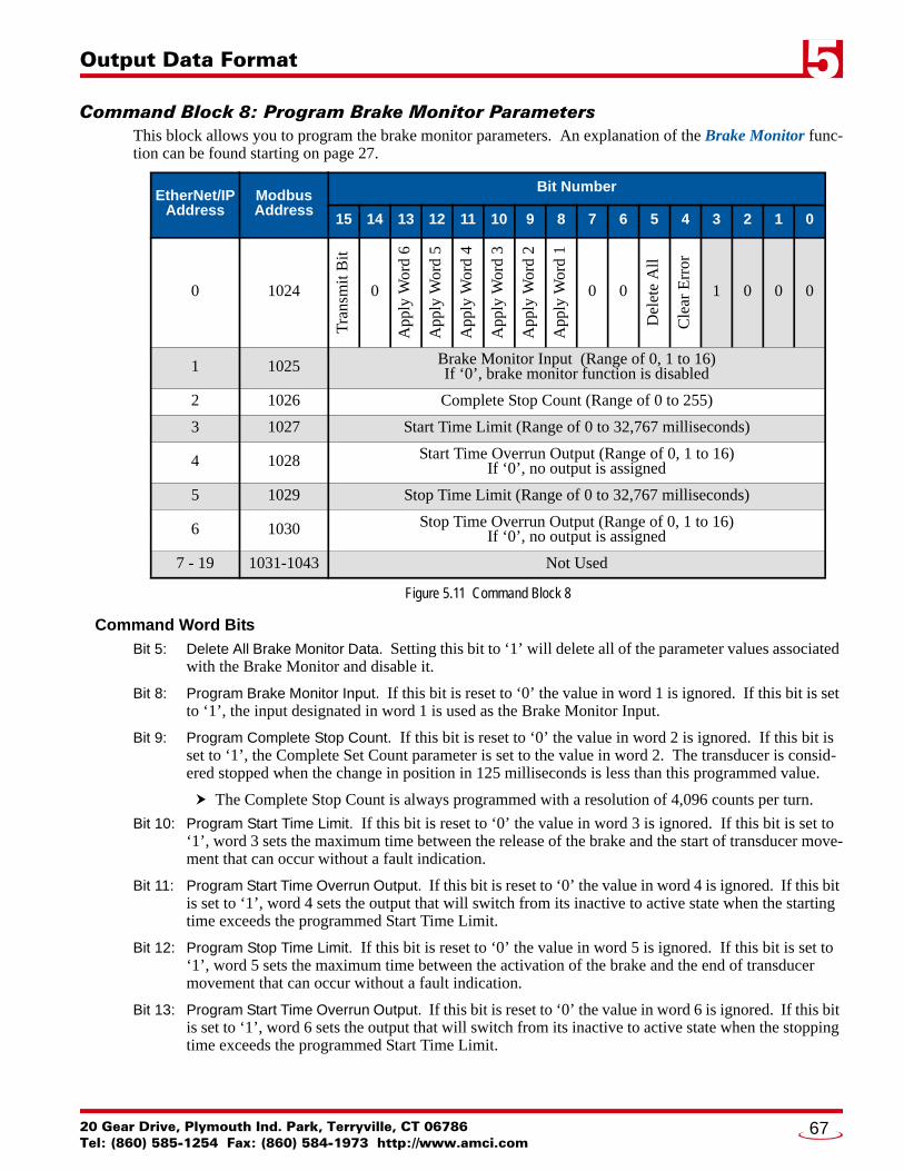
Output Data Format 5
Command Block 8: Program Brake Monitor ParametersThis block allows you to program the brake monitor parameters. An explanation of the Brake Monitor func-tion can be found starting on page 27.
Figure 5.11 Command Block 8
Command Word Bits
Bit 5: Delete All Brake Monitor Data. Setting this bit to ‘1’ will delete all of the parameter values associated with the Brake Monitor and disable it.
Bit 8: Program Brake Monitor Input. If this bit is reset to ‘0’ the value in word 1 is ignored. If this bit is set to ‘1’, the input designated in word 1 is used as the Brake Monitor Input.
Bit 9: Program Complete Stop Count. If this bit is reset to ‘0’ the value in word 2 is ignored. If this bit is set to ‘1’, the Complete Set Count parameter is set to the value in word 2. The transducer is consid-ered stopped when the change in position in 125 milliseconds is less than this programmed value.
The Complete Stop Count is always programmed with a resolution of 4,096 counts per turn.
Bit 10: Program Start Time Limit. If this bit is reset to ‘0’ the value in word 3 is ignored. If this bit is set to ‘1’, word 3 sets the maximum time between the release of the brake and the start of transducer move-ment that can occur without a fault indication.
Bit 11: Program Start Time Overrun Output. If this bit is reset to ‘0’ the value in word 4 is ignored. If this bit is set to ‘1’, word 4 sets the output that will switch from its inactive to active state when the starting time exceeds the programmed Start Time Limit.
Bit 12: Program Stop Time Limit. If this bit is reset to ‘0’ the value in word 5 is ignored. If this bit is set to ‘1’, word 5 sets the maximum time between the activation of the brake and the end of transducer movement that can occur without a fault indication.
Bit 13: Program Start Time Overrun Output. If this bit is reset to ‘0’ the value in word 6 is ignored. If this bit is set to ‘1’, word 6 sets the output that will switch from its inactive to active state when the stopping time exceeds the programmed Start Time Limit.
EtherNet/IPAddress
ModbusAddress
Bit Number
15 14 13 12 11 10 9 8 7 6 5 4 3 2 1 0
0 1024
Tra
nsm
it B
it
0
App
ly W
ord
6
App
ly W
ord
5
App
ly W
ord
4
App
ly W
ord
3
App
ly W
ord
2
App
ly W
ord
1
0 0
Del
ete
All
Cle
ar E
rror
1 0 0 0
1 1025 Brake Monitor Input (Range of 0, 1 to 16)If ‘0’, brake monitor function is disabled
2 1026 Complete Stop Count (Range of 0 to 255)
3 1027 Start Time Limit (Range of 0 to 32,767 milliseconds)
4 1028 Start Time Overrun Output (Range of 0, 1 to 16)If ‘0’, no output is assigned
5 1029 Stop Time Limit (Range of 0 to 32,767 milliseconds)
6 1030 Stop Time Overrun Output (Range of 0, 1 to 16)If ‘0’, no output is assigned
7 - 19 1031-1043 Not Used
20 Gear Drive, Plymouth Ind. Park, Terryville, CT 06786Tel: (860) 585-1254 Fax: (860) 584-1973 http://www.amci.com
67

Output Data Format5
Command Block 9: Program Shift Register ParametersThis block allows you to program the shift register parameters. An explanation of the Shift Register function can be found in the Shift Register ANDing section of the manual starting on page 25.
1) This block only programs the shift register parameters. Command Block 6: Program LS Enabling Parameters on page 62 is used to program which shift register bit is used to control an output.
2) If the Shift Register is disabled, all outputs that have a shift register bit assigned to them will be disabled.
Figure 5.12 Command Block 9
Command Word Bits
Bit 5: Delete All Shift Register Data. Setting this bit to ‘1’ will delete all of the parameter values associated with the Shift Register and disable it.
Bit 8: Program Shift Register Parameters. If this bit is reset to ‘0’ the shift register parameter are left at their previous values. If this bit is set to ‘1’, words 1 through 4 are used to program the shift register parameters.
EtherNet/IPAddress
ModbusAddress
Bit Number
15 14 13 12 11 10 9 8 7 6 5 4 3 2 1 0
0 1024
Tra
nsm
it B
it
0 0 0 0 0 0
App
ly W
ords
1-4
0 0
Del
ete
All
Cle
ar E
rror
1 0 0 1
1 1025 Shift Register Input (Range of 0, 1 to 16)If ‘0’, the shift register function is disabled
2 1026 Shift Register FROM setpoint (Range of 0 to (Full Scale Count -1))
3 1027 Shift Register TO setpoint (Range of 0 to (Full Scale Count -1))
4 1028 Shift Position (Range of 0 to (Full Scale Count -1))
5 - 19 1029-1043 Not Used
ADVANCED MICRO CONTROLS INC.68

Output Data Format 5
Command Block 10: Program Production Cycle ParametersThis block allows you to program the Production Cycle parameters, which affect the part counters available on the ANS1.
Figure 5.13 Command Block 10
Command Word Bits
Bit 8: Program Production Cycle Increment Position Parameter. If this bit is reset to ‘0’ the Production Cycle Increment Position parameter is left at its previous value. If this bit is set to ‘1’, the Production Cycle Increment Position parameter is set to the value contained in word 1.
Bit 9: Program Production Cycle Multiplier / Divisor Parameters. If this bit is reset to ‘0’ the Production Cycle Multiplier and Production Cycle Divisor parameters are left at their previous values. If this bit is set to ‘1’, the Production Cycle Multiplier parameter is set to the value contained in word 2 and the Production Cycle Divisor parameter is set to the value contained in word 3.
EtherNet/IPAddress
ModbusAddress
Bit Number
15 14 13 12 11 10 9 8 7 6 5 4 3 2 1 0
0 1024
Tra
nsm
it B
it
0 0 0 0 0
App
ly W
ords
2&
3
App
ly W
ord
1
0 0 0
Cle
ar E
rror
1 0 1 0
1 1025 Production Cycle Increment Position (Range of 0 to (Full Scale Count -1))
2 1026 Production Cycle Multiplier (Range of 1 to 32,767)
3 1027 Production Cycle Divisor (Range of 1 to 32,767)
4 - 19 1028-1043 Not Used
20 Gear Drive, Plymouth Ind. Park, Terryville, CT 06786Tel: (860) 585-1254 Fax: (860) 584-1973 http://www.amci.com
69

Output Data Format5
Command Block 11: Program Production Counter ParametersThis block allows you to program the parameters of the production counters.
† These words must equal zero when programming the Machine Revolutions and Good Parts Counters. (When word 1 equals 4 or 5)
Figure 5.14 Command Block 11
Word 1: Counter Number
This word defines the counter that the rest of the command block programs. The Production Counters sec-tion of the manual, which starts on page 34, describes the six counters available on the ANS1.
EtherNet/IPAddress
ModbusAddress
Bit Number
15 14 13 12 11 10 9 8 7 6 5 4 3 2 1 0
0 1024
Tra
nsm
it B
it
0 0
App
ly W
ords
7 &
8
App
ly W
ords
5 &
6
App
ly W
ord
4
App
ly W
ord
3
App
ly W
ord
2
0 0
Del
ete
All
Cle
ar E
rror
1 0 1 1
1 1025 Counter Number (Range of 0 to 5)See description below
2 1026 Counter Overflow Output† (Range of 0, 1...16)If ‘0’, no overflow output is assigned to the counter
3 1027 Counter Overflow Mode† (Range of 0...2)
4 1028Batch Counter Increment Mode
‘0’: Counter increments after each complete cycle‘1’: Counter increments after a cycle without Die Protection Fault
5 1029 Counter Limit Value (32 bit)†
(Range of 0 to 999,999,999 [0x0000 0000 to 0x3B9A C9FF])6 1030
7 1031 Counter Preset Value (32 bit)(Range of 0 to 999,999,999 [0x0000 0000 to 0x3B9A C9FF])8 1032
9-19 1033-1043 Not Used
Counter Number(Word 1 Value) Counter
0 Part Cycle Counter. This counter increments based on the Production Cycle Multiplier and Divisor values.
1 Batch Counter 1
2 Batch Counter 2
3 Batch Counter 3
4 Machine Revolutions Counter. This counter increments every machine cycle.
5 Good Part Counter. Counter increments with the Part Cycle Counter if no die protection faults occurred during the part cycle.
ADVANCED MICRO CONTROLS INC.70

Output Data Format 5
Command Block 11: Program Production Counter Parameters (continued)Word 0: Command Word Bits
Bit 5: Delete Counter Data. Setting this bit to ‘1’ will delete all of the parameter values associated with the counter given in word 1.
Bit 8: Program Counter Overflow Output. If this bit is reset to ‘0’ the Counter Overflow Output parameter is left at its previous value. If this bit is set to ‘1’, the Counter Overflow Output parameter is set to the value contained in word 2. You must also have a Counter Limit Value programmed on the coun-ter that you are assigning this output to. This bit must equal ‘0’ when the counter number in word 1 equals ‘4’ or ‘5’.
Bit 9: Program Counter Overflow Mode. If this bit is reset to ‘0’ the Counter Overflow Mode parameter is left at its previous value. If this bit is set to ‘1’, the Counter Overflow Mode parameter is set to the value contained in word 3. Valid values for word 3 are:
Bit 10: Program Batch Counter Increment Mode. If this bit is reset to ‘0’ the Batch Counter Increment Mode parameter is left at its previous value. If this bit is set to ‘1’, the Batch Counter Increment Mode parameter is set to the value contained in word 4.
Bit 11: Program Counter Limit Value. If this bit is reset to ‘0’ the Counter Limit Value parameter is left at its previous value. If this bit is set to ‘1’, the Counter Limit Value parameter is set to the 32 bit value contained in words 4 and 5. This bit must equal ‘0’ when the counter number in word 1 equals ‘4’ or ‘5’.
Bit 12: Preset Counter. If this bit is reset to ‘0’ the counter’s count is left at its previous value. If this bit is set to ‘1’, the counter’s count is set to the 32 bit value contained in words 6 and 7.
The Counter Limit Value and the Counter Preset Values programmed in words 4 through 7 are treated as 32 bit values, withe the upper sixteen bits of the value in the first word and the lower sixteen bits of the value in the second word. When entering these values in host controllers that only display signed sixteen bit integers, it may be easier to convert your values to hexa-decimal and enter them as hexadecimal numbers in your host controller. For example, if you want a Counter Limit Value of 40,000, convert this number to a 32 bit hexadecimal number before entering it. (40,000 = 0x0000 9C40. If you then view these numbers as signed sixteen bit integers, they will appear as 0 in the first word and -25,536 in the second.)
Word 3 Value Counter Overflow Mode
0 No Output (The value in word 2 must also be zero.)
1Output Goes Active. The output changes from its inactive to its active state when the counter reaches its programmed count limit. The output changes back to its inactive state at the start of a new production cycle.
2 Output Toggles. The output changes state when the counter reaches its programmed count limit.
20 Gear Drive, Plymouth Ind. Park, Terryville, CT 06786Tel: (860) 585-1254 Fax: (860) 584-1973 http://www.amci.com
71

Output Data Format5
Command Block 15: Save/Restore ProgramThis block allows you to save module programming to the internal memory of the ANS1. You can also use this block to restore a program, which allows you to program the ANS1 on power up with a single command.
Figure 5.15 Command Block 15
Command Word Bits
Bit 5: Delete All Programs. Setting this bit to ‘1’ will delete all programs stored in the ANS1. Parameter values of the active program will remain in RAM. If power is cycled before these parameters are saved to a program, the ANS1 will power up with factory default settings.
Bit 8: Load Program. Setting this bit to ‘1’ will load the program into memory that is defined by word 1. This bit and bit 9 cannot be set at the same time.
Bit 9: Save Program. Setting this bit to ‘1’ will save the present programming into the program that is defined by word 1. This bit and bit 8 cannot be set at the same time.
Bit 10: Save Global Parameters. Setting this bit to ‘1’ will save the Global Machine Configuration and Brake Monitor Setup parameters to FLASH memory. The Global Machine Configuration parameters are programmed using command block 2 as described starting on page 56 and the Brake Monitor Setup parameters are programmed using command block 8 as described starting on page 67.
Word 1 Values
The FLASH memory used on the ANS1 is limited to 100,000 write cycles. Exceeding this value may cause damage to the module.
EtherNet/IPAddress
ModbusAddress
Bit Number
15 14 13 12 11 10 9 8 7 6 5 4 3 2 1 0
0 1024
Tra
nsm
it B
it
0 0 0 0
Sav
e G
loba
l
Sav
e Pr
gm
Loa
d P
rgm
0 0
Del
ete
All
Cle
ar E
rror
1 1 1 1
1 1025 Program Number to act on (Range of 0, 1-39, 40)See description below
2-19 1026-1043 Not Used
Word 1 Value Program
0Active Program When reading a program from memory, this block will have no effect. When saving a program to memory, the last program read from memory will be stored to.
1 - 39 Program Number
40Factory Default Used when reading a program only. This value will restore factory defaults for all parameters in RAM.
ADVANCED MICRO CONTROLS INC.72

20 Gear Drive, Plymouth IndTel: (860) 585-1254 Fax: (8
CHAPTER 6
INPUT DATA FORMATAvailable Data Attribute BlocksYou will use the Command Block 1: Define Return Data and I/O Forces command block to tell the ANS1 which Data Attribute Block it should return. For convenience, the data attribute number table is repeated here. The complete format of Command Block 1 can be found starting on page 54.
Data Attribute Number
Table 6.1 Return Data Attribute Number Listing
Status Word 0The first word of every Data Attribute Block is the same.
Figure 6.1 Command Word Format
The ANS1 reports back machine state and programming data through fourteen dif-ferent data attribute blocks. The format of these blocks are defined in this chap-ter.
Word 1 Value Returned Attribute Additional Parameter Format
Definition
0 Global Setup Data page 75
1 LS Setpoint Programming Requested LS Output number in word 2 page 76
2 LS Output Adjustment Programming Requested LS Output number in word 2 page 77
3 LS Enable Programming Requested LS Output number in word 2 page 78
4 Die Monitor Programming Requested Die Monitor Input in word 3 page 79
5 Brake Monitor Programming Requested Brake Monitor Input in word 3 page 80
6 Shift Register Programming page 81
7 Production Cycle Programming page 81
8 Counting Modes Programming page 82
16 Machine Status Data Additional data for Output defined in word 2 Additional data for Input defined in word 3 page 83
17 Counter Values page 85
18 Die Monitor States Additional data for Input defined in word 3 page 86
19 Brake Monitor and Output Advances States
Additional data for Output defined in word 2 Additional data for Input defined in word 3 page 87
20 Shift Register State page 88
EtherNet/IPAddress
ModbusAddress
Bit Number
15 14 13 12 11 10 9 8 7 6 5 4 3 2 1 0
0 0
Ack
now
ledg
e B
it
Hea
rtbe
at
Har
dwar
e F
ault
Res
olve
r F
ault
Program Fault Bits
RP
M C
lam
ped
Out
put F
orce
d
0 Data Attribute Block Number
. Park, Terryville, CT 0678660) 584-1973 http://www.amci.com
73

Input Data Format6
Status Word 0 (continued)Bit Values
Bit 15: Acknowledge Bit. Set to ‘1’ in response to accepting a command block with its Transmit bit set to ‘1’. The Acknowledge bit will reset to ‘0’ in response to the Transmit bit being reset to ‘0’.
Bit 14: Heartbeat Bit. This bit changes state every 500 milliseconds and can be used to verify the health of the ANS1 and active communications between the ANS1 and your host controller.
Bit 13: Hardware Fault. Most common cause is an error in the checksum of the program last read from memory. This fault also is used to indicate a communications error between modules in an AnyNET-I/O Stack, or errors in communicating with the interface to the industrial (host) network.
Bit 12: Resolver Fault. This error will only occur if the resolver input is used for position feedback. The ANS1 cannot decode the position from the attached resolver. This error is typically caused by cabling problems. Refer to the Installation chapter, starting with the Transducer Cabling section on page 41. AMCI also has an FAQ on our website that will help you troubleshoot resolver installations. A direct link to the FAQ is:
http://www.amci.com/pdfs/faqs/how-test-amci-resolver-system.pdf
Bits 11-8: Programming Error. These bits show if there were any programming errors in the last Command Block sent to the ANS1 with its Transmit Bit set to ‘1’.
Table 6.2 Command Error Bits
Bit 7: RPM Clamped. This bit is set when one of the calculated advances exceeds one machine cycle.
Bit 6: Output Forced. This bit is set to ‘1’ if any of the outputs have been either forced on or off. Use words 1 and 2 of the Data Attribute Block 0 to determine which outputs have been forced.
Bits 4-0: Data Attribute Block Number. The number of the Data Attribute Block presently being transmit-ted by the ANS1.
Error Bits Programming Error
0000 No errors
1000Command Word Error. This error will be cleared when the next correct Command Word is transmitted to the ANS1.
1001Parameter Error One of the parameters in the last Command Block was outside of its defined range. This error requires that the Clear Error command bit be used to clear this error.
1010
Reserved Bits Error One or more reserved bit in the Command Block were set to ‘1’. All reserved bits must equal ‘0’. This error requires that the Clear Error command bit be used to clear this error.
1011Parameter Conflict Error Two parameters, or their associated “Apply Word” bits in the command word, are set in such a way that the programming command cannot be accepted. This error requires that the Clear Error command bit be used to clear this error.
1100Setpoint Overlap Error The ranges defined by multiple setpoint pairs on an output cannot overlap. This error requires that the Clear Error command bit be used to clear this error.
ADVANCED MICRO CONTROLS INC.74

Input Data Format 6
Data Attribute 0: Global Setup DataBits in word 5 are defined in the Global Machine Bit Parameters (Word 1) section on page 57.
Figure 6.2 Global Setup Data Format (Data Attribute 0)
EtherNet/IPAddress
ModbusAddress
Bit Number
15 14 13 12 11 10 9 8 7 6 5 4 3 2 1 0
0 0
Ack
now
ledg
e
Hea
rtbe
at
Har
dwar
e F
ault
Res
olve
r F
ault
Program Fault Bits
RP
M C
lam
ped
Out
put F
orce
d
0 0 0 0 0 0
1 1Outputs Forced High (Bit 0 = Output 1 ... Bit 15 = Output 16) If bit is ‘1’, output is forced on. If bit = ‘0’, output is not forced on. Word = 0x0000 when no outputs are force on.
2 2Outputs Forced Low (Bit 0 = Output 1 ... Bit 15 = Output 16) If bit is ‘1’, output is not forced off. If bit = ‘0’, output is forced off. Word = 0xFFFF when no outputs are force off.
3 3Inputs Forced High (Bit 0 = Input 1 ... Bit 15 = Input 16) If bit is ‘1’, input is forced on. If bit = ‘0’, input is not forced on. Word = 0x0000 when no inputs are force on.
4 4Inputs Forced Low (Bit 0 = Input 1 ... Bit 15 = Input 16) If bit is ‘1’, input is not forced off. If bit = ‘0’, input is forced off. Word = 0xFFFF when no inputs are force off.
5 5 0 0 0 0 0 0 0 0 0 0 0
Hol
dOut
s
Qua
dEnc
Slav
eMod
e
XF
ltL
atch
Cnt
Dir
6 6 Counts per Cycle parameter value
7 7 Full Scale Count parameter value
8 8 Preset Machine Offset. Can be Scaled Machine Offset parameter value of the calculated offset that resulted from a position preset operation.
9 9 Machine Preset Value parameter value
10 10 Machine Preset Input parameter value
11 11 RPM Filter parameter value
12 12
Input Active State (Bit 0 = Output 1 ... Bit 15 = Output 16) If bit = ‘0’, the active state of the input is when current is flowing through it. If bit = ‘1’, the active state of the input is when current is not flowing through it.
13 13 AnyNET-I/O module ID (83, ASCII “S”)
14 14 AMCI LS Product Code (39)
15 15 Product Major Revision
16 16 Product Minor Revision
17 17 Active Program Number
18-19 18-19 Not Used
20 Gear Drive, Plymouth Ind. Park, Terryville, CT 06786Tel: (860) 585-1254 Fax: (860) 584-1973 http://www.amci.com
75

Input Data Format6
Data Attribute 1: LS Setpoint Programming DataFigure 6.3 LS Setpoint Data Format (Data Attribute 1)
EtherNet/IPAddress
ModbusAddress
Bit Number
15 14 13 12 11 10 9 8 7 6 5 4 3 2 1 0
0 0
Ack
now
ledg
e
Hea
rtbe
at
Har
dwar
e F
ault
Res
olve
r F
ault
Program Fault Bits
RP
M C
lam
ped
Out
put F
orce
d
0 0 0 0 0 1
1 1 Selected Output Point Number (See Word 2, Command Block 1, page 54)
2 2 Programmed FROM Setpoint 1
3 3 Programmed TO Setpoint 1
4 4 ON Stitch Distance 1
5 5 OFF Stitch Distance 1
6 6 Programmed FROM Setpoint 2
7 7 Programmed TO Setpoint 2
8 8 ON Stitch Distance 2
9 9 OFF Stitch Distance 2
10 10 Programmed FROM Setpoint 3
11 11 Programmed TO Setpoint 3
12 12 ON Stitch Distance 3
13 13 OFF Stitch Distance 3
14 14 Programmed FROM Setpoint 4
15 15 Programmed TO Setpoint 4
16 16 ON Stitch Distance 4
17 17 OFF Stitch Distance 4
18-19 18-19 Not Used
ADVANCED MICRO CONTROLS INC.76

Input Data Format 6
Data Attribute 2: LS Output Adjustments DataFigure 6.4 LS Output Adjustments Data Format (Data Attribute 2)
EtherNet/IPAddress
ModbusAddress
Bit Number
15 14 13 12 11 10 9 8 7 6 5 4 3 2 1 0
0 0
Ack
now
ledg
e
Hea
rtbe
at
Har
dwar
e F
ault
Res
olve
r F
ault
Program Fault Bits
RP
M C
lam
ped
Out
put F
orce
d
0 0 0 0 1 0
1 1 Selected Output Point Number (See Word 2, Command Block 1, page 54)
2 2 Programmed Limit Switch Offset
3 3 Programmed LS Preset Input Number
4 4 Programmed LS Preset Value
5 5 Programmed Lead (Fixed) Advance Time
6 6 Programmed Variable Advance Time
7 7 Programmed Trail Advance Time
8 8 Programmed LS Timer Value
9 9 Programmed Timed Output Type If programmed as a Time Only output, this word will be non-zero
10 10 Programmed RPM Enable Low Setpoint
11 11 Programmed RPM Enable High Setpoint
12 12 Programmed Shift Register Bit Number
13-19 13-19 Not Used
20 Gear Drive, Plymouth Ind. Park, Terryville, CT 06786Tel: (860) 585-1254 Fax: (860) 584-1973 http://www.amci.com
77

Input Data Format6
Data Attribute 3: Enabling Input Programming DataFigure 6.5 Enabling Input Data Format (Data Attribute 3)
EtherNet/IPAddress
ModbusAddress
Bit Number
15 14 13 12 11 10 9 8 7 6 5 4 3 2 1 0
0 0
Ack
now
ledg
e
Hea
rtbe
at
Har
dwar
e F
ault
Res
olve
r F
ault
Program Fault Bits
RP
M C
lam
ped
Out
put F
orce
d
0 0 0 0 1 1
1 1 Selected Output Point Number (See Word 2, Command Block 1, page 54)
2 2
Input 1 Enabling Condition ‘0’ = Input not used for Enable ANDing ‘1’ = Simple ANDing ‘2’ = Pulse ANDing ‘3’ = Window ANDing
3 3 Input 2 Enabling Condition
4 4 Input 3 Enabling Condition
5 5 Input 4 Enabling Condition
6 6 Input 5 Enabling Condition
7 7 Input 6 Enabling Condition
8 8 Input 7 Enabling Condition
9 9 Input 8 Enabling Condition
10 10 Input 9 Enabling Condition
11 11 Input 10 Enabling Condition
12 12 Input 11 Enabling Condition
13 13 Input 12 Enabling Condition
14 14 Input 13 Enabling Condition
15 15 Input 14 Enabling Condition
16 16 Input 15 Enabling Condition
17 17 Input 16 Enabling Condition
18 18 Position Window Low Limit
19 19 Position Window High Limit
ADVANCED MICRO CONTROLS INC.78

Input Data Format 6
Data Attribute 4: Die Monitor Setup DataFigure 6.6 Die Monitor Setup Format (Data Attribute 4)
Check Mode Values
EtherNet/IPAddress
ModbusAddress
Bit Number
15 14 13 12 11 10 9 8 7 6 5 4 3 2 1 0
0 0
Ack
now
ledg
e
Hea
rtbe
at
Har
dwar
e F
ault
Res
olve
r F
ault
Program Fault Bits
RP
M C
lam
ped
Out
put F
orce
d
0 0 0 1 0 0
1 1 Fault Output Point Number ‘0’ if no fault output is associated with this Die Protection monitor.
2 2 Selected Input Point Number (See Word 3, Command Block 1, page 54.)
3 3 Check Mode (See description below.)
4 4 Check Window 1 Leading Edge
5 5 Check Window 1 Trailing Edge
6 6 Check Window 2 Leading Edge
7 7 Check Window 2 Trailing Edge
8 8 Check Window 3 Leading Edge
9 9 Check Window 3 Trailing Edge
10 10 Check Window 4 Leading Edge
11 11 Check Window 4 Trailing Edge
12 12 Die Monitor Action Mode (See description below.)
13-19 13-19 Not Used
Check Mode(Word 3 Value) Result
0 Disable Die Protection Monitoring on the input given in word 2.
1 Normally True Check (Setpoints in words 4-11 are not used.)
2 Normally False Check (Setpoints in words 4-11 are not used.)
3 Cyclic Check
4 Constant Check
5 Quick Check
20 Gear Drive, Plymouth Ind. Park, Terryville, CT 06786Tel: (860) 585-1254 Fax: (860) 584-1973 http://www.amci.com
79

Input Data Format6
Data Attribute 4: Die Monitor Setup Data (continued)Die Monitor Action Mode Values.
Data Attribute 5: Brake Monitor Setup Data
Figure 6.7 Brake Monitor Setup Data Format (Data Attribute 5)
Action Mode(Word 12 Value) Result
0 Die Protection Fault Counter will continuously count.Disable associated output when fault counter is non-zero.
1Die Protection Fault Counter will reset to zero when cycle completes without a die protection fault.Disable associated output when fault counter is non-zero.
2 Die Protection Fault Counter will continuously count.Associated output is disconnected from the monitor and is always active.
3Die Protection Fault Counter will reset to zero when cycle completes without a die protection fault.Associated output is disconnected from the monitor and is always active.
EtherNet/IPAddress
ModbusAddress
Bit Number
15 14 13 12 11 10 9 8 7 6 5 4 3 2 1 0
0 0
Ack
now
ledg
e
Hea
rtbe
at
Har
dwar
e F
ault
Res
olve
r F
ault
Program Fault Bits
RP
M C
lam
ped
Out
put F
orce
d
0 0 0 1 0 1
1 1 Brake Input Number
2 2 Complete Stop Count parameter
3 3 Start Time Limit parameter
4 4 Start Time Overrun Output (‘0’ if no output assigned to this function)
5 5 Stop Time Limit parameter
6 6 Stop Time Overrun Output (‘0’ if no output assigned to this function)
7-19 7-19 Not Used
ADVANCED MICRO CONTROLS INC.80

Input Data Format 6
Data Attribute 6: Shift Register Setup DataFigure 6.8 Shift Register Setup Data Format (Data Attribute 6)
Data Attribute 7: Production Cycle Setup Data
Figure 6.9 Production Cycle Setup Data Format (Data Attribute 7)
EtherNet/IPAddress
ModbusAddress
Bit Number
15 14 13 12 11 10 9 8 7 6 5 4 3 2 1 0
0 0
Ack
now
ledg
e
Hea
rtbe
at
Har
dwar
e F
ault
Res
olve
r F
ault
Program Fault Bits
RP
M C
lam
ped
Out
put F
orce
d
0 0 0 1 1 0
1 1 Shift Register Input Number If ‘0’, the shift register function is disabled
2 2 Shift Register FROM Setpoint
3 3 Shift Register TO Setpoint
4 4 Shift Position
5-19 5-19 Not Used
EtherNet/IPAddress
ModbusAddress
Bit Number
15 14 13 12 11 10 9 8 7 6 5 4 3 2 1 0
0 0
Ack
now
ledg
e
Hea
rtbe
at
Har
dwar
e F
ault
Res
olve
r F
ault
Program Fault Bits
RPM
Cla
mpe
d
Out
put F
orce
d
0 0 0 1 1 1
1 1 Production Cycle Increment Position
2 2 Production Cycle Multiplier
3 3 Production Cycle Divisor
4-19 4-19 Not Used
20 Gear Drive, Plymouth Ind. Park, Terryville, CT 06786Tel: (860) 585-1254 Fax: (860) 584-1973 http://www.amci.com
81

Input Data Format6
Data Attribute 8: Counter Setup DataFigure 6.10 Counter Setup Data Format (Data Attribute 8)
EtherNet/IPAddress
ModbusAddress
Bit Number
15 14 13 12 11 10 9 8 7 6 5 4 3 2 1 0
0 0
Ack
now
ledg
e
Hea
rtbe
at
Har
dwar
e F
ault
Res
olve
r F
ault
Program Fault Bits
RP
M C
lam
ped
Out
put F
orce
d
0 1 0 0 0 1
1 1 Output Assigned to Part Cycle Counter Overflow (Range of 0, 1...16)
2 2 Programmed Count Limit for Part Cycle Counter 32 bit integer. Lower 16 bits in word 33 3
4 4 Output Assigned to Batch Counter 1 Overflow (Range of 0, 1...16)
5 5Output Mode for Batch Counter 1 ‘0’ = No Output Assigned ‘1’ = Output goes active ‘2’ = Output toggles state
6 6Increment Mode for Batch Counter 1 ‘0’ = Increment every cycle ‘1’ = Increment on cycle without Die Protection Fault
7 7 Programmed Count Limit for Batch Counter 1 32 bit integer. Lower 16 bits in word 88 8
9 9 Output Assigned to Batch Counter 2 Overflow (Range of 0, 1...16)
10 10 Output Mode for Batch Counter 2 (See word 5 above for range)
11 11 Increment Mode for Batch Counter 2 (See word 6 above for range)
12 12 Programmed Count Limit for Batch Counter 2 32 bit integer. Lower 16 bits in word 1313 13
14 14 Output Assigned to Batch Counter 3 Overflow (Range of 0, 1...16)
15 15 Output Mode for Batch Counter 3 (See word 5 above for range)
16 16 Increment Mode for Batch Counter 3 (See word 6 above for range)
17 17 Programmed Count Limit for Batch Counter 3 32 bit integer. Lower 16 bits in word 1818 18
19 19 Not Used
ADVANCED MICRO CONTROLS INC.82

Input Data Format 6
Data Attribute 16: Machine Status Data(continued on next page)
EtherNet/IPAddress
ModbusAddress
Bit Number
15 14 13 12 11 10 9 8 7 6 5 4 3 2 1 0
0 0
Ack
now
ledg
e
Hea
rtbe
at
Har
dwar
e F
ault
Res
olve
r F
ault
Program Fault Bits
RP
M C
lam
ped
Out
put F
orce
d
0 1 0 0 0 0
1 1 Machine Position
2 2Machine Speed in RPM When using a resolver, the sign of value indicates direction of rotation. With default programming and wiring, the value is negative for counter-clockwise rotation.
3 3 Production Rate (Machine Speed * Production Multiplier / Production Divisor)
4 4Time of Rotation Time it took for the shaft to complete its last rotation. Resolution of 0.1 milliseconds. (A value of ‘123’ means the last rotation took 12.3 milliseconds to complete.)
5 5 State of Inputs (Bit 0 = Input 1 ... Bit 15 = Input 16)
6 6 Selected Input Point Number (See Word 3, Command Block 1, page 54.)
7 7 Rising Position of Selected Input Last position where the input made an inactive-to-active transition.
8 8 Falling Position of Selected Input Last position where the input made an active-to-inactive transition.
9 9 State of Outputs (Bit 0 = Input 1 ... Bit 15 = Input 16)
10 10Calculated State of Outputs (Bit 0 = Input 1 ... Bit 15 = Input 16) Output state with advances, but without Enabling or Timed parameters applied.
11 11Simple Enabled Outputs (Bit 0 = Input 1 ... Bit 15 = Input 16) These bits are normally ‘1’. A bit is reset to ‘0’ if the output is disabled by an input configured for Simple ANDing.
12 12Pulse Enabled Outputs (Bit 0 = Input 1 ... Bit 15 = Input 16) These bits are normally ‘1’. A bit is reset to ‘0’ if the output is disabled by an input configured for Pulse ANDing.
13 13Windowed Enabled Outputs (Bit 0 = Input 1 ... Bit 15 = Input 16) These bits are normally ‘1’. A bit is reset to ‘0’ if the output is disabled by an input configured for Window ANDing.
14 14Shift Register Enabled Outputs (Bit 0 = Input 1 ... Bit 15 = Input 16) These bits are normally ‘1’. A bit is reset to ‘0’ if the output is disabled because the associated bit in the Shift Register equals ‘0’.
20 Gear Drive, Plymouth Ind. Park, Terryville, CT 06786Tel: (860) 585-1254 Fax: (860) 584-1973 http://www.amci.com
83

Input Data Format6
Data Attribute 16: Machine Status Data (continued)Figure 6.11 Machine Status Data Format (Data Attribute 16)
EtherNet/IPAddress
ModbusAddress
Bit Number
15 14 13 12 11 10 9 8 7 6 5 4 3 2 1 0
15 15
RPM Enabled Outputs (Bit 0 = Input 1 ... Bit 15 = Input 16) These bits are normally ‘1’. A bit is reset to ‘0’ if the output is disabled because the machine speed is outside the programmed speed range.
16 16Time Expired Outputs (Bit 0 = Input 1 ... Bit 15 = Input 16) These bits are normally ‘1’. A bit is reset to ‘0’ if the output is off because its programmed timer value has expired.
17 17
User Defined Outputs (Bit 0 = Input 1 ... Bit 15 = Input 16) These bits are normally ‘1’. A bit is reset to ‘0’ if the output is disabled because it is a user defined output that is in its disabled state. (Start Time Overrun, Stop Time Overrun, Counter Overflow)
18 18 Selected Output Point Number (See Word 2, Command Block 1, page 54)
19 19Corrected Position of Selected Output Present position used by the output. It is equal to the Machine Position with the programmed Limit Switch Offset applied.
ADVANCED MICRO CONTROLS INC.84
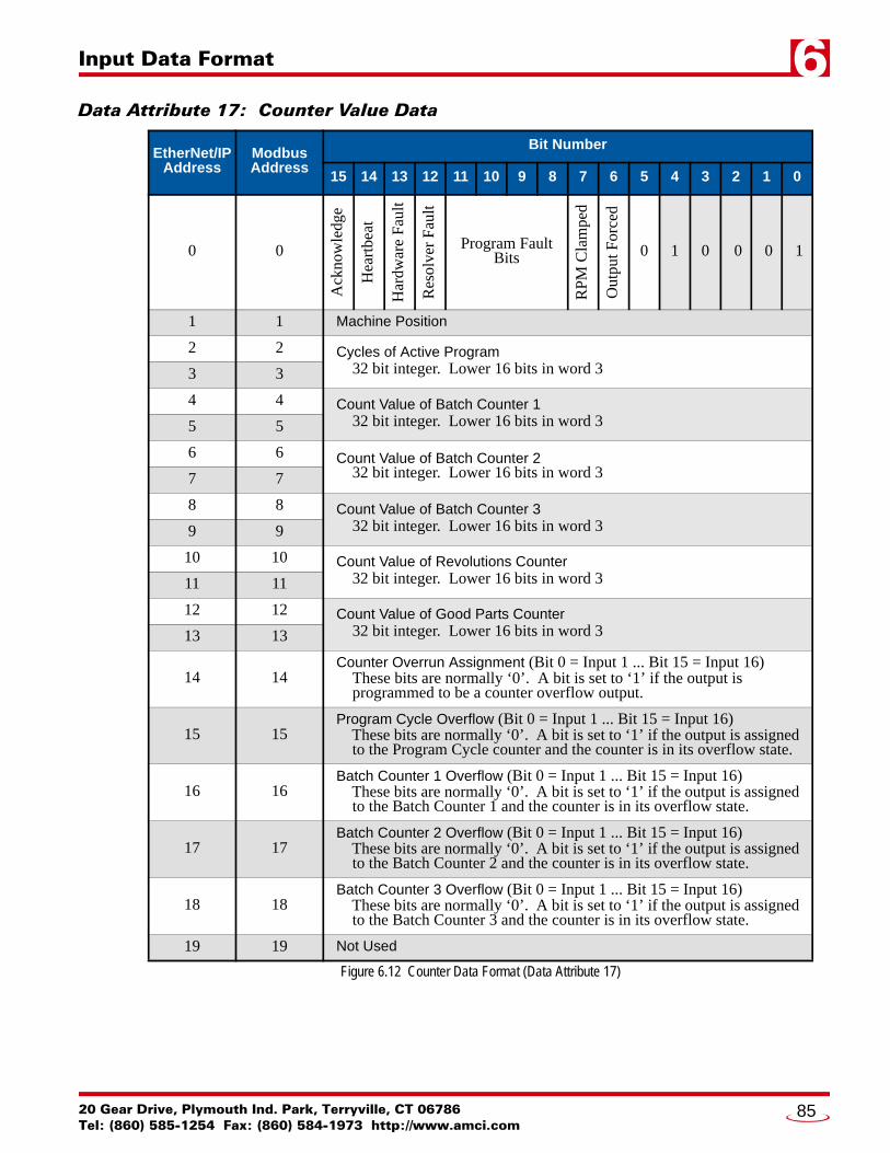
Input Data Format 6
Data Attribute 17: Counter Value DataFigure 6.12 Counter Data Format (Data Attribute 17)
EtherNet/IPAddress
ModbusAddress
Bit Number
15 14 13 12 11 10 9 8 7 6 5 4 3 2 1 0
0 0
Ack
now
ledg
e
Hea
rtbe
at
Har
dwar
e F
ault
Res
olve
r F
ault
Program Fault Bits
RP
M C
lam
ped
Out
put F
orce
d
0 1 0 0 0 1
1 1 Machine Position
2 2 Cycles of Active Program 32 bit integer. Lower 16 bits in word 33 3
4 4 Count Value of Batch Counter 1 32 bit integer. Lower 16 bits in word 35 5
6 6 Count Value of Batch Counter 2 32 bit integer. Lower 16 bits in word 37 7
8 8 Count Value of Batch Counter 3 32 bit integer. Lower 16 bits in word 39 9
10 10 Count Value of Revolutions Counter 32 bit integer. Lower 16 bits in word 311 11
12 12 Count Value of Good Parts Counter 32 bit integer. Lower 16 bits in word 313 13
14 14Counter Overrun Assignment (Bit 0 = Input 1 ... Bit 15 = Input 16) These bits are normally ‘0’. A bit is set to ‘1’ if the output is programmed to be a counter overflow output.
15 15Program Cycle Overflow (Bit 0 = Input 1 ... Bit 15 = Input 16) These bits are normally ‘0’. A bit is set to ‘1’ if the output is assigned to the Program Cycle counter and the counter is in its overflow state.
16 16Batch Counter 1 Overflow (Bit 0 = Input 1 ... Bit 15 = Input 16) These bits are normally ‘0’. A bit is set to ‘1’ if the output is assigned to the Batch Counter 1 and the counter is in its overflow state.
17 17Batch Counter 2 Overflow (Bit 0 = Input 1 ... Bit 15 = Input 16) These bits are normally ‘0’. A bit is set to ‘1’ if the output is assigned to the Batch Counter 2 and the counter is in its overflow state.
18 18Batch Counter 3 Overflow (Bit 0 = Input 1 ... Bit 15 = Input 16) These bits are normally ‘0’. A bit is set to ‘1’ if the output is assigned to the Batch Counter 3 and the counter is in its overflow state.
19 19 Not Used
20 Gear Drive, Plymouth Ind. Park, Terryville, CT 06786Tel: (860) 585-1254 Fax: (860) 584-1973 http://www.amci.com
85

Input Data Format6
Data Attribute 18: Die Monitor DataFigure 6.13 Die Monitor Data Format (Data Attribute 18)
EtherNet/IPAddress
ModbusAddress
Bit Number
15 14 13 12 11 10 9 8 7 6 5 4 3 2 1 0
0 0
Ack
now
ledg
e
Hea
rtbe
at
Har
dwar
e F
ault
Res
olve
r F
ault
Program Fault Bits
RP
M C
lam
ped
Out
put F
orce
d
0 1 0 0 1 0
1 1 Machine Position
2 2
State of Fault Outputs (Bit 0 = Output 1 ... Bit 15 = Output 16) Bit equals ‘0’ if the output is not assigned as a D.P. Fault Output. Bit equals ‘1’ if the output is a D.P. Fault Output and a fault has not occurred.Bit equals ‘0’ if the output is a D.P. Fault Output and a fault has occurred.
3 3State of Fault Inputs (Bit 0 = Input 1 ... Bit 15 = Input 16) Bit equals ‘0’ if the input is not assigned as a D.P. Input. Bit shows actual state of the input if it is assigned as a D.P. Input.
4 4First Input to Fault (Bit 0 = Input 1 ... Bit 15 = Input 16) Bit equals ‘1’ if the associated input was the first to fault in the present production cycle.
5 5Faulted Die Protection Inputs (Bit 0 = Input 1 ... Bit 15 = Input 16) Bit equals ‘1’ if the associated input has a fault on it in the present production cycle.
6 6 Selected Input Point Number (See Word 3, Command Block 1, page 54.)
7 7Number of Faults on the Selected Input Die Protection Fault Counter value for the selected input.
8 8 Rising Position of Selected Input Last position where the input made an inactive-to-active transition.
9 9 Falling Position of Selected Input Last position where the input made an active-to-inactive transition.
10-19 10-19 Not Used
ADVANCED MICRO CONTROLS INC.86

Input Data Format 6
Data Attribute 19: Brake Monitor and Output Advance DataFigure 6.14 Brake Monitor and Output Advance Data Format (Data Attribute 19)
EtherNet/IPAddress
ModbusAddress
Bit Number
15 14 13 12 11 10 9 8 7 6 5 4 3 2 1 0
0 0
Ack
now
ledg
e
Hea
rtbe
at
Har
dwar
e F
ault
Res
olve
r F
ault
Program Fault Bits
RP
M C
lam
ped
Out
put F
orce
d
0 1 0 0 1 1
1 1 Machine Position
2 2
State of Brake Input (Bit 0 = Input 1 ... Bit 15 = Input 16) Bit equals ‘0’ if the input is not assigned as the Brake Input. Bit equals the present state of the input if it is assigned as the Brake Input.
3 3Brake Released Position Position where the Brake Input made its inactive-to-active transition.
4 4
Start Time Value (reported in milliseconds) Time between when the brake was released and a position change greater than (2 * Complete Stop Count value). If the time exceeds 32,767 milliseconds, a value of 32,768 is recorded.
5 5Brake Applied Position Position where the Brake Input made its active-to-inactive transition.
6 6Stop Time Value (reported in milliseconds) Time between when the brake was released and a position change less than the Complete Stop Count value in 125 milliseconds.
7 7 State of Outputs (Bit 0 = Input 1 ... Bit 15 = Input 16)
8 8 Selected Output Point Number (See Word 2, Command Block 1, page 54)
9 9Leading Edge Count Advanced Number of counts the leading edge of the limit switch output will be advanced, based on the programmed Lead Advance Time, and the present speed of the machine.
10 10Trailing Edge Count Advanced Number of counts the trailing edge of the limit switch output will be advanced, based on the programmed Trail Advance Time, and the present speed of the machine.
11-19 11-19 Not Used
20 Gear Drive, Plymouth Ind. Park, Terryville, CT 06786Tel: (860) 585-1254 Fax: (860) 584-1973 http://www.amci.com
87

Input Data Format6
Data Attribute 20: Shift Register Data(continued on next page)
EtherNet/IPAddress
ModbusAddress
Bit Number
15 14 13 12 11 10 9 8 7 6 5 4 3 2 1 0
0 0
Ack
now
ledg
e
Hea
rtbe
at
Har
dwar
e F
ault
Res
olve
r F
ault
Program Fault Bits
RP
M C
lam
ped
Out
put F
orce
d
0 1 0 1 0 0
1 1 Machine Position
2 2
State of Shift Register Input (Bit 0 = Input 1 ... Bit 15 = Input 16) Bit equals ‘0’ if the input is not assigned as the Shift Register Input. Bit equals the present state of the input if it is assigned as the Shift Register Input.
3 3 State of Outputs (Bit 0 = Input 1 ... Bit 15 = Input 16)
4 4 Shift Register Bit Pattern Word 1 Bit 0 = Shift Register Bit 1 ... Bit 15 = Shift Register Bit 16.
5 5 Shift Register Bit Pattern Word 2 Bit 0 = Shift Register Bit 17 ... Bit 15 = Shift Register Bit 32.
6 6 Shift Register Bit Pattern Word 3 Bit 0 = Shift Register Bit 33 ... Bit 15 = Shift Register Bit 48.
7 7 Shift Register Bit Pattern Word 4 Bit 0 = Shift Register Bit 49 ... Bit 15 = Shift Register Bit 64.
8 8 Shift Register Bit Pattern Word 5 Bit 0 = Shift Register Bit 65 ... Bit 15 = Shift Register Bit 80.
9 9 Shift Register Bit Pattern Word 6 Bit 0 = Shift Register Bit 81 ... Bit 15 = Shift Register Bit 96.
10 10 Shift Register Bit Pattern Word 7 Bit 0 = Shift Register Bit 97 ... Bit 15 = Shift Register Bit 112.
11 11 Shift Register Bit Pattern Word 8 Bit 0 = Shift Register Bit 113 ... Bit 15 = Shift Register Bit 128.
12 12 Shift Register Bit Pattern Word 9 Bit 0 = Shift Register Bit 129 ... Bit 15 = Shift Register Bit 144.
13 13 Shift Register Bit Pattern Word 10 Bit 0 = Shift Register Bit 145 ... Bit 15 = Shift Register Bit 160.
14 14 Shift Register Bit Pattern Word 11 Bit 0 = Shift Register Bit 161 ... Bit 15 = Shift Register Bit 176.
15 15 Shift Register Bit Pattern Word 12 Bit 0 = Shift Register Bit 177 ... Bit 15 = Shift Register Bit 192.
16 16 Shift Register Bit Pattern Word 13 Bit 0 = Shift Register Bit 193 ... Bit 15 = Shift Register Bit 208.
ADVANCED MICRO CONTROLS INC.88

Input Data Format 6
Data Attribute 20: Shift Register Data (continued)Figure 6.15 Brake Monitor and Output Advance Data Format (Data Attribute 20)
EtherNet/IPAddress
ModbusAddress
Bit Number
15 14 13 12 11 10 9 8 7 6 5 4 3 2 1 0
17 17 Shift Register Bit Pattern Word 14 Bit 0 = Shift Register Bit 209 ... Bit 15 = Shift Register Bit 224.
18 18 Shift Register Bit Pattern Word 15 Bit 0 = Shift Register Bit 225 ... Bit 15 = Shift Register Bit 240.
19 19 Shift Register Bit Pattern Word 16 Bit 0 = Shift Register Bit 241 ... Bit 15 = Shift Register Bit 256.
20 Gear Drive, Plymouth Ind. Park, Terryville, CT 06786Tel: (860) 585-1254 Fax: (860) 584-1973 http://www.amci.com
89

ADVANCED MICRO CONTROLS INC.
LEADERS IN ADVANCED CONTROL PRODUCTS