advanced graphics – lecture one 3d graphics and computational geometry alex benton, university of...
Post on 19-Dec-2015
224 views
TRANSCRIPT

Advanced Graphics – Lecture One
3D Graphics and Computational GeometryAlex Benton, University of Cambridge – [email protected]
Supported in part by Google UK, Ltd

Applications of 3D Graphics
(a) “Wall-E”, Pixar, 2008 (b) Image from CSB Biomolecular Visualization Workshop, Vanderbilt University, Oct 2007 (c) Two stages of an Invisalign treatment, Align Technology (d) Google Earth (e) World of Warcraft, from South Park 1008 “Make Love not Warcraft”

From model to image
Geometry
Mathematics
. . .
Rendering Pipeline
3D scanning
Modeling
(b) 3D Studio Max, by Autodesk, from oman3d.com (c) 3D scanning project by IBM (d) scanned output image (IBM)

Today’s technologies Java
• Common, re-usable language; extremely well-designed
• Steadily increasing popularity in industry
• Weak but evolving 3D support C++
• Long-established language• Long history with OpenGL
• Technically C has the long history. C++ never really improved it.
• Long history with DirectX• Losing popularity in some fields
(finance, web) but still strong in others (games, medical)
OpenGL• Open source with many
implementations• Extraordinarily well-designed, old,
but still evolving• Fairly cross-platform
DirectX/Direct3d• Less well-designed• Microsoft™ only
• DX 10 requires Vista!
• But! Dependable updates… Java3D
• Poor cross-platform support (surprisingly!)
• Available by GPL; community-developed

OpenGL
OpenGL is…• hardware-independent
• operating system independent
• vendor neutral OpenGL is a state-based renderer
• set up the state, then pass in data: data is modified by existing state
• very different from the OOP model, where data would carry its own state

OpenGL
OpenGL is platform-independent, but implementations are platform-specific and often rely on the presence of native libraries• Great support for Windows, Mac, linux, etc• Support for mobile devices with OpenGL-ES
• Including Google Android! Accelerates common 3D graphics operations
• Clipping (for primitives)• Hidden-surface removal (Z-buffering)• Texturing, alpha blending (transparency)• NURBS and other advanced primitives (GLUT)

OpenGL in Java: JOGL JOGL is the Java binding for OpenGL.
• JOGL apps can be deployed as applications or as applets.
• This means that you can embed 3D in a web page.
• (If the user has installed the latest Java, of course.)
• Admittedly, applets are somewhat “1998”. Using JOGL:
• You can download JOGL from https://jogl.dev.java.net/ (choose the “current release build” link)
• In win32: You’ll want to add the contents of the .zip to your CLASSPATH and PATH system vars
• In eclipse: In Project->Properties->Java Build Path->Libraries, add jogl.jar and gluegen-rt.jar.
• To deploy an embedded applet, you’ll use Sun’s JNLP wrappers, which provide signed applets wrapped around native JOGL binaries.

A quick intro to JOGL: Hello Squarepublic class HelloSquare { public static void main(String[] args) { new Thread() { public void run() { Frame frame = new Frame("Hello Square"); GLCanvas canvas = new GLCanvas();
// Setup GL canvas frame.add(canvas); canvas.addGLEventListener(new Renderer()); // Setup AWT frame frame.setSize(400, 400); frame.addWindowListener(new WindowAdapter(){ public void windowClosing(WindowEvent e) { System.exit(0); } }); frame.setVisible(true);
// Render loop while(true) { canvas.display(); } } }.start(); }}
public class Renderer implements GLEventListener { public void init(GLAutoDrawable glDrawable) { final GL gl = glDrawable.getGL(); gl.glClearColor(0.2f, 0.4f, 0.6f, 0.0f); }
public void display(GLAutoDrawable glDrawable) { final GL gl = glDrawable.getGL(); gl.glClear(GL.GL_COLOR_BUFFER_BIT); gl.glLoadIdentity(); gl.glTranslatef(0, 0, -5);
gl.glBegin(GL.GL_QUADS); gl.glVertex3f(-1, -1, 0); gl.glVertex3f( 1, -1, 0); gl.glVertex3f( 1, 1, 0); gl.glVertex3f(-1, 1, 0); gl.glEnd(); }
public void reshape(GLAutoDrawable gLDrawable, int x, int y, int width, int height) {
final GL gl = gLDrawable.getGL(); final float h = (float)width / (float)height; gl.glMatrixMode(GL.GL_PROJECTION); gl.glLoadIdentity(); (new GLU()).gluPerspective(50, h, 1, 1000); gl.glMatrixMode(GL.GL_MODELVIEW); }}

1) Shaded square
Jazzing up the squarepublic void vertex(GL gl, float x, float y, float z) {
gl.glColor3f( (x+1)/2.0f, (y+1)/2.0f, (z+1)/2.0f); gl.glVertex3f(x, y, z);}
public void sphere(GL gl, double u, double v) {
vertex(gl, cos(u)*cos(v), sin(u)*cos(v), sin(v));
}
//...for (double u = 0; u <= 2*PI;
u += 0.1) { for (double v = 0; v <= PI;
v += 0.1) { sphere(gl, u, v); sphere(gl, u+0.1, v); sphere(gl, u+0.1, v+0.1); sphere(gl, u, v+0.1); }}
2) Parametric sphere
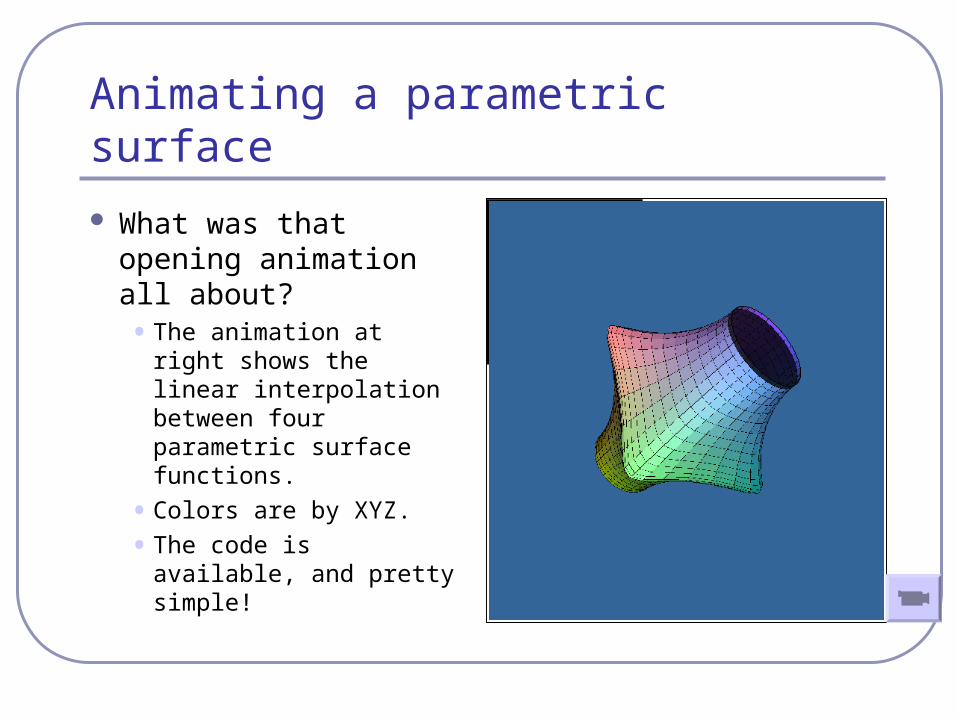
Animating a parametric surface
What was that opening animation all about?• The animation at right
shows the linear interpolation between four parametric surface functions.
• Colors are by XYZ.
• The code is available, and pretty simple!
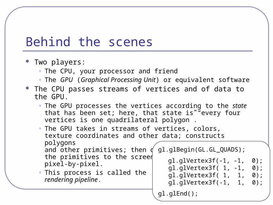
Behind the scenes
Two players:• The CPU, your processor and friend
• The GPU (Graphical Processing Unit) or equivalent software The CPU passes streams of vertices and of data to the GPU.
• The GPU processes the vertices according to the state that has been set; here, that state is “every four vertices is one quadrilateral polygon”.
• The GPU takes in streams of vertices, colors, texture coordinates and other data; constructs polygons and other primitives; then draws the primitives to the screen pixel-by-pixel.
• This process is called therendering pipeline.
gl.glBegin(GL.GL_QUADS);
gl.glVertex3f(-1, -1, 0);gl.glVertex3f( 1, -1, 0);gl.glVertex3f( 1, 1, 0);gl.glVertex3f(-1, 1, 0);
gl.glEnd();

Anatomy of a rendering pipeline
1) Geometry is defined in local space. The vertices and coordinates of a surface are specified relative to a local basis and origin.
This encourages re-use and replication of geometry; it also saves the tedious math of storing rotations and other transformations within the vertices of the shape itself.
This means that changing the position of a highly complex object requires only changing a 4x4 matrix instead of recalculating all vertex values.
World space
Viewing space
3D screen space
2D display space
Local space

Anatomy of a rendering pipeline
2) The pipeline transforms vertices and surface normals from local to world space.
A series of matrices are concatenated together to form the single transformation which is applied to each vertex. The rendering engine (e.g., OpenGL) is responsible for associating the state that transforms each group of vertices with the actual vertex values themselves.
World space
Viewing space
3D screen space
2D display space
Local space

Anatomy of a rendering pipeline
3) Rotate and translate the geometry from world space to viewing or camera space.
At this stage, all vertices are positioned relative to the point of view of the camera. (The world really does revolve around you!)
For example, a cube at (10,000, 0, 0) viewed from a camera (9,999, 0, 0) would now have relative position (1, 0, 0). Rotations would have similar effect.
This makes operations such as clipping and hidden-object removal much faster.
Viewing space
World space
3D screen space
2D display space
Local space

Anatomy of a rendering pipeline
4) Perspective: Transform the viewing frustrum into an axis-aligned box with the near clip plane at z=0 and the far clip plane at z=1. Coordinates are now in 3D screen space.
This transformation is not affine: angles will distort and scales change.
Hidden-surface removal can be accelerated here by clipping objects and primitives against the viewing frustrum. Depending on implementation this clipping could be before transformation or after or both.
3D screen space
World space
Viewing space
2D display space
Local space

Anatomy of a rendering pipeline
5) Collapse the box to a plane. Rasterize primitives using Z-axis information for depth-sorting and hidden-surface-removal.
Clip primitives to the screen.
Scale raster image to the final raster buffer and rasterize primitives.
2D display space
World space
Viewing space
3D screen space
Local space

Overview of a rendering pipeline
Object definition
Local space
Scene composition
Viewing frame definition
Lighting definition
World space
Backface culling
Viewing frustum culling
HUD definition
Viewing
space
Hidden-surface removal
Scan conversion
Shading
3D screen space
Image
Display space
P’ = S2D • V2S • W2V • L2W • PL
L2W W2V
V2S
S2D

Transforms you may recognize
Translation1 0 0 x
0 1 0 y
0 0 1 z
0 0 0 1
Rotation by t around Y cos(t) 0 sin(t) 0
0 1 0 0
-sin(t) 0 cos(t) 0
0 0 0 1
Scalingx 0 0 0
0 y 0 0
0 0 z 0
0 0 0 1
Perspectived/h 0 0 0
0 d/h 0 0
0 0 f/(f-d) –df/(f-d)
0 0 1 0(Watt, pp.149—153)

Why were they 4x4?
We do all this in homogeneous coordinates.• [X, Y, Z, W] H → [X/W, Y/W, Z/W]
• [A, B, C] → [A, B, C, 1]H
Why?• Translation
1 0 0 x a a+x0 1 0 y b = b+y0 0 1 z c c+z0 0 0 1 1 1
• Perspective – yields X/Z, Y/Z. (Try it!)

OpenGL’s matrix stacks
Recall: matrix multiplication is associative but not commutative.• ABC = A(BC) = (AB)C ≠ ACB ≠ BCA
Pre-multiplying matrices that will be used more than once is faster than multiplying many matrices every time you render a primitive.
OpenGL uses matrix stacks to store stacks of matrices, where the topmost matrix is (generally) the product of all matrices below.• This allows you to build a local frame of reference—
local space—and apply transforms within that space.
A
AB
ABC

Scene graphs and matrix stacks
Matrix stacks are designed for nested relative transforms.
glPushMatrix(); glTranslatef(0,0,-5); glPushMatrix(); glRotatef(45,0,1,0); renderSquare(); glPopMatrix(); glPushMatrix(); glRotatef(-45,0,1,0); renderSquare(); glPopMatrix();glPopMatrix();
identity
T
identity
T
T • R1
identity
T
T • R2
identity
T
…
Send primitives

The scene graph A scene graph is a tree of scene
elements where a child’s transform is relative to its parent.
The final transform of the child is the ordered product of all of its ancestors in the tree.
OpenGL’s matrix stack and depth-first traversal of your scene graph: two great tastes that go great together!
MfingerToWorld = (Mperson • Mtorso • Marm • Mhand • Mfinger)
Person
Torso
Arm Arm Leg …
Hand
Finger
…
…
…

Great for…
• Collision detection between scene elements
• Culling before rendering
• Accelerating ray-tracing
Your scene graph and you A common optimization
derived from the scene graph is the propagation of bounding volumes.• These take many forms:
bounding spheres, axis-aligned bounding boxes, oriented bounding boxes…
Nested bounding volumes allow the rapid culling of large portions of geometry• Test against the bounding
volume of the top of the scene graph and then work down.

Your scene graph and you Many 2D GUIs today favor an event model in which events ‘bubble
up’ from child windows to parents. This is sometimes mirrored in a scene graph.• Ex: a child changes size, which changes the size of the parent’s bounding box
• Ex: the user drags a movable control in the scene, triggering an update event If you do choose this approach, consider using the model/ view/
controller design pattern. 3D geometry objects are good for displaying data but they are not the proper place for control logic.• For example, the class that stores the geometry of the rocket should not be the
same class that stores the logic that moves the rocket.
• Always separate logic from representation.
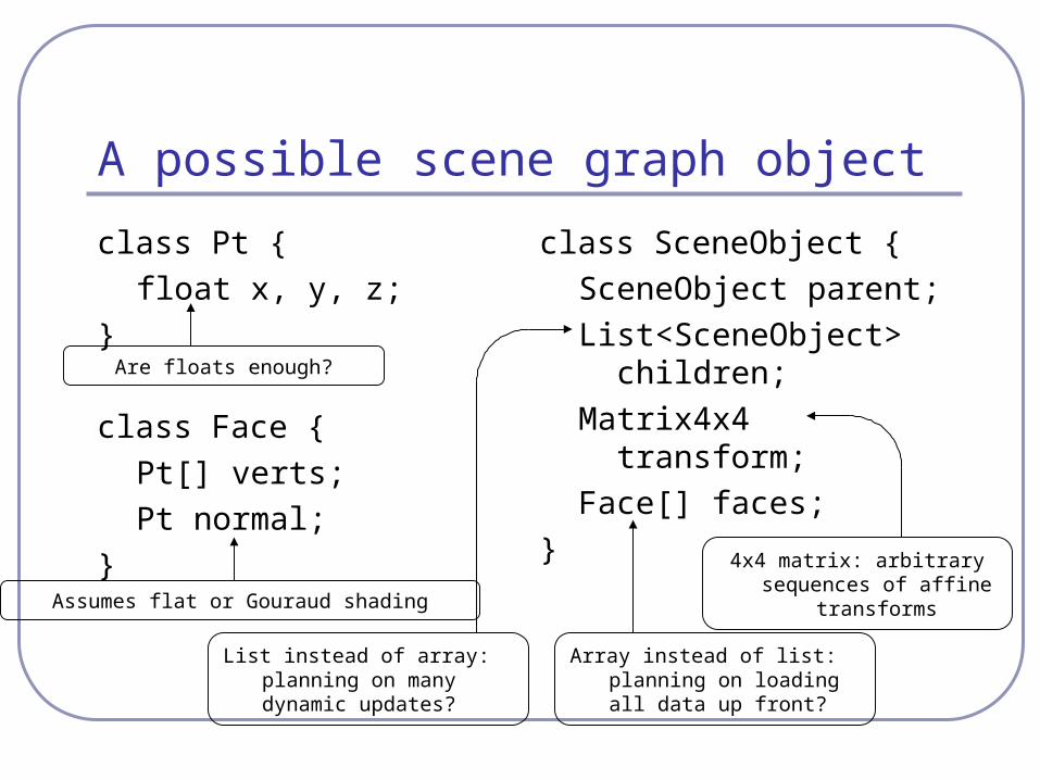
A possible scene graph object
class Pt {
float x, y, z;
}
class Face {
Pt[] verts;
Pt normal;
}
class SceneObject {
SceneObject parent;
List<SceneObject> children;
Matrix4x4 transform;
Face[] faces;
}
Assumes flat or Gouraud shading
4x4 matrix: arbitrary sequences of affine
transforms
Are floats enough?
List instead of array: planning on many dynamic updates?
Array instead of list: planning on loading all data up front?

Polygon data structures
When designing your data structures, consider interactions and interrogations.• If you’re going to move vertices, you’ll need to update
faces.
• If you’re going to render with crease angles, you’ll need to track edges.
• If you want to be able to calculate vertex normals or curvature, your vertices will have to know about surrounding faces.
• Is memory a factor? What about the processing overhead of dereferencing a pointer or array?

Improving the sample scene object Vertex order matters
• Usually anticlockwise about the face normal
Could store normal at the vertex• Phong shading
Vertices could track faces Could introduce edges,
tracking vertices and faces together
Could store color at the face or at the vertex; depends on lighting model
Same for other material traits (shading, bump maps, …)
Texture data has to be at the vertices
A “winged edge” data structure
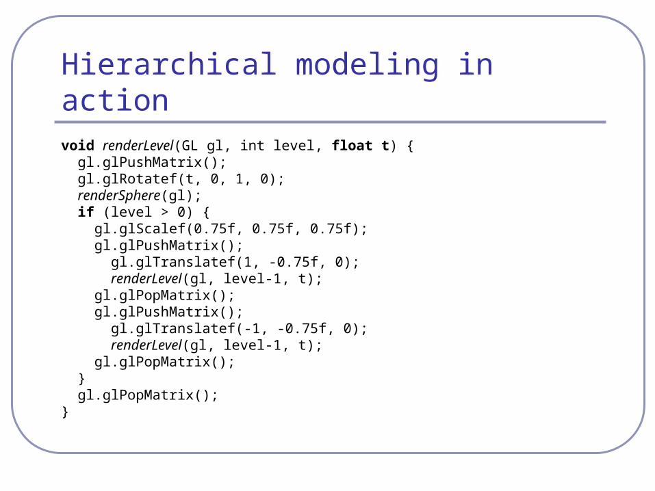
Hierarchical modeling in actionvoid renderLevel(GL gl, int level, float t) { gl.glPushMatrix(); gl.glRotatef(t, 0, 1, 0); renderSphere(gl); if (level > 0) { gl.glScalef(0.75f, 0.75f, 0.75f); gl.glPushMatrix(); gl.glTranslatef(1, -0.75f, 0); renderLevel(gl, level-1, t); gl.glPopMatrix(); gl.glPushMatrix(); gl.glTranslatef(-1, -0.75f, 0); renderLevel(gl, level-1, t); gl.glPopMatrix(); } gl.glPopMatrix();}

Hierarchical modeling in action

Recommended reading
The OpenGL Programming Guide• Some folks also favor The OpenGL Superbible for
code samples and demos
• There’s also an OpenGL-ES reference, same series
The Graphics Gems series by Glassner et al• All the maths you’ve already forgotten
The NeonHelium online OpenGL tutorials• http://nehe.gamedev.net/