advanced construction materials for high temperature steam
TRANSCRIPT

Chapter 0
Advanced Construction Materials for HighTemperature Steam PEM Electrolysers
Aleksey Nikiforov, Erik Christensen, Irina Petrushina, Jens Oluf Jensenand Niels J. Bjerrum
Additional information is available at the end of the chapter
http://dx.doi.org/10.5772/51928
1. Introduction
1.1. Principles of polymer electrolyte membrane (PEM) water electrolysis
There are main 3 types of electrolyzers: alkaline, acidic and solid oxide electrolyzer cell(SOEC). This chapter will be concentrated on acidic electrolyzers, where reactions follow thepathes (reactions 1, 2).
cathode : 2 H+ + 2 e− → H2 (1)
anode : H2O → 12
O2 + 2 H+ + 2 e− (2)
The efficiency of water splitting by electrolysis is rather low for conventional electrolyzers andthere is hence a large potential for improvement.
The modern acidic electrolysers use polymeric proton conducting membranes, e.g. Nafion®
or PBI, doped with phosphoric acid.
One of the potential advantages of PEM cells over more abundant alkaline electrolyzers is thatthey were shown to be reversible [21, 31, 69]. The type of an electrochemical cell working bothas a fuel cell and a water electrolyzer is called a unitized regenerative fuel cells (URFC) [13, 38,67, 70]. These devices produce hydrogen from water in the electrolysis mode, while electricitycan be inversely produced in the fuel cell mode. This mode of working is beneficial when thelack of electricity changes with the excess energy available (periods of low consumption) [61].
PEM water electrolysis technology is frequently presented in literature as a potentially veryeffective alternative to more conventional alkaline water electrolysis [43, 46, 47]. Amongadvantages are higher production rates and energy efficiency [60]. In a future “hydrogensociety" this method is envisioned as a part of the “energy cycle", where hydrogen acts as anenergy carrier. In this cycle, electricity from renewable energy sources is used in electrolysisfor electrochemical splitting of water [26]. PEM cells usually use perfluorinated ion-exchangemembranes as an electrolyte (known under the trademark Nafion®).
©2012 Nikiforov et al., licensee InTech. This is an open access chapter distributed under the terms of theCreative Commons Attribution License (http://creativecommons.org/licenses/by/3.0), which permitsunrestricted use, distribution, and reproduction in any medium, provided the original work is properlycited.
Chapter 4

2 Will-be-set-by-IN-TECH
In a PEM cell the electrolyte is a solid ion-exchange membrane, which does not involvecompulsory circulation of electrolyte through it. Different types of ionic membranes will bediscussed in Section 2. The electrodes are usually directly sprayed or pressed on the oppositesites of the solid polymer electrolyte (SPE), thus being the origin of a membrane electrodeassembly (MEA)[1, 5, 67, 78]. Also, electrodes can be sprayed on the gas diffusion layer (GDL),and then put together leaving the SPE between them [56, 79]. A PEM electrolyzer stackconsists of a combination of several cells (as many as 100), electrically connected in series [54].The cells are separated from each other by a metal plate (also called a bipolar plate), whichserves both as a current collector and as an interconnect to the next cell in the stack. Flows ofevolved hydrogen and oxygen are usually swept out through the bipolar plate by water flowand further separated from it outside the cell.
Several commercial types of PEM electrolyzers are available today on the market [27–29].Some units have power up to 44 kW and claimed lifetime up to 40,000 hours. Still, the maindrawbacks of such systems are the price of materials and complex system components, whichensures save and reliable function.
1.2. High temperature PEM electrolysis. Advantages and drawbacks
At temperatures above the boiling point of water, the energy efficiency of water splitting canbe significantly improved because of decreased thermodynamic energy requirements, whichis one of the major advantages of these systems.
Since water electrolysis becomes increasingly heat consuming with temperature (Figure 1),larger portion of the total energy demand can be provided as heat at elevated temperatures.This provides an opportunity to utilize the Joule heat, that is inevitably produced due to thepassage of electrical current through the cell. In this way, the overall electricity consumptionand, thereby, the H2 production price can be reduced.
Figure 1. The theoretical cell voltage as a function of temperature [35]
62 Electrolysis

Advanced Construction Materials for High Temperature Steam PEM Electrolysers 3
Since the reaction of water splitting is not spontaneous and the Gibbs free energy is positive, apositive change of a factor T · ΔS� in the equation 3 means less energy needs to be applied. Asthe reaction has a positive entropy, the equilibrium will be displaced towards the products forhigh temperatures. The term T · ΔS� increases with increasing temperature, thus increasingthe contribution of thermal energy to the total needs for the water splitting reaction [66].Therefore, the part of heat, which can be used for the reaction is higher, meaning that theproduction costs of hydrogen are decreased [58]. It was noticed much earlier that econonomicreasons force to move towards high temperature electrolysis (120-150 °C) [73].
ΔG� = ΔH� − T · ΔS�
ΔG� = −nFΔE�
ΔS� > 0 → dG�dT
< 0
dΔE�dT
= − dΔG�dT
> 0
(3)
According to the Arrhenius’ equation 4, the kinetics of the electrode reactions is enhancedat elevated temperatures. It is associated with lower overpotentials at the electrodes, givinghigher efficiency for electrolysis.
k f = EA f exp
(ΔG‡
cRT
)(4)
Another positive opportunity provided while operating at temperatures above 100 °C is thatwater is not in a liquid phase (at ambient pressure) and this fact significantly simplifieswater/gas management. In this case all the reactant/product flows are in a steam phaseand the transport of them is easier, which provides simplified stack construction andoperation [44].
The heat management is also easier for high temperature systems, as the heat flow out ofthe system is proportional to the temperature gradient between the cell and the ambient.This means that cooling is more effective in elevated-temperature systems, as there are lessefficiency losses associated with the forced cooling of the cell [36].
Another benefit of high temperature systems is attributed to the decreased sensibility ofcatalysts towards poisoning by adsorption of inhibiting agents. This effect is acknowledgedto be a considerable advantage of high temperature PEM fuel cells (HTPEMFCs) [44]. Theinhibition mechanism usually involves chemisorption of species on the catalyst surface,covering and screening it from interacting with the reactants. This adsorption is weaker athigher temperatures, giving higher tolerance to impurities [16].
However, with increasing temperature, the probability and rate of side processes, such asdissolution of the electrodes and components corrosion, is higher. This decreases the lifetimeof the whole system and increases demands to all materials used with respect to corrosion andthermal stability [19, 46]. The corrosion issue for construction materials in such cells will beaddressed in the following Section 3.
63Advanced Construction Materials for High Temperature Steam PEM Electrolysers

4 Will-be-set-by-IN-TECH
2. Acidic electrolytes and polymer electrolyte membranes technology
The electrolyte is one of the main components of any type of electrolyzer. The importance ofthe electrolyte is emphasized by the fact that the type of electrolyzer, as well as of fuel cell,is named after the type of electrolyte used. In the classical view it is traditionally a solutionof acid, base or water soluble salt in the water. When added, those dissociate into ions in thesolution, which increases conductivity of pure water.
The acidic water electrolysis traditionally uses sulphuric or phosphoric acid as they are stablewithin the potential window of water. The acid increases the conductivity of water throughthe donating protons.
The polymer electrolyte membrane (PEM) is a membrane which acts as a proton conductorin electrolyzer cell. Usually, the ionic membrane consists of a solid polytetrafluoroethylene(PTFE) backbone, which is chemically altered and contains sulfonic ionic functional groupsthus the pendant side chains terminated with−SO3−. The acid dissociates and release protonsby the following mechanism (5):
SO3H−=> SO−3 + H+ (5)
The membranes of this type allow water molecules to penetrate into its structure, whileremaining not permeable to molecular H2 and O2. The sulfonic groups are responsible for thetransfer of protons during electrolysis, where a hydrated proton H3O+ can freely move withinthe polymer matrix, while a sulfonate ion SO3− is fixed to the side chain of polymer. Whenelectric current flows across the membrane, the hydrated protons are attracted to the cathode,where they are combined into hydrogen. Nafion® is the most known trademark among ionicmembranes and is patented by Du Pont Company in 1966 [15]. A typical membrane has athickness in the range of 50-100 μmeters and this type of membrane is commonly used asan electrolyte for conventional PEM water electrolyzers [23, 56, 79]. These membranes haveexcellent chemical stability, high ionic conductivity and excellent mechanical strength [56].Water electrolysis using Nafion® as an electrolyte is a promising technology for large-scalehydrogen production [8, 75].
The conductivity of such membranes decreases significantly at temperatures above 80°C, which is associated with the ion of water content [42, 45]. Sufficient efficiency isachieved using Poly[2,2’-(m-phenylene)-5,5’-bibenzimidazole (PBI) membranes doped withphosphoric acid in PEM fuel cells at temperatures up to 200 °C under ambient pressure [36,44, 45]. The structure of PBI is shown in Figure 2. Doped PBI membranes are a potentialelectrolyte for use in PEM steam electrolyzer systems. The ionic conductivity of membranesincreases with temperature [45], which means the higher the working temperature is, thelower ohmic losses through electrolyte are. In spite of that, the conditions of extremely lowpH combined with high overpotentials at the anodic compartment of the oxygen evolutionelectrode (OEE) impose serious limitations on materials which can be used in these cells.
In the laboratory conditions commonly 0.5M sulphuric acid is used for screening electrodematerials in a 3-electrode electrochemical cells, simulating conditions of the Nafion®-basedsystems, which work at temperatures below 100 °C [51, 52]. Since high temperature PEM cellsare working at temperatures around 150 °C, H2SO4 cannot be used to simulate conditionsin the 3-electrode cell, even at high concentration. Instead, concentrated H3PO4 can benused, which permits to work at temperatures as high as 150-160 °C, depending on thecomposition [14].
64 Electrolysis

Advanced Construction Materials for High Temperature Steam PEM Electrolysers 5
Figure 2. General structure of Poly[2,2’-(m-phenylene)-5,5’-bibenzimidazole (PBI) [45].
However, it was noticed by Appleby and Van Drunen that the Tafel slopes for nobleelectrocatalysts are significantly higher in concentrated phosphoric acid than those for morediluted solutions, being the apparent cause of adsorption of electrolyte on the electrodesurface [7].
As it was stated by Miller in one of his latest publications [55], the cost of Nafion®-basedpolymers calls for alternative membrane materials along with higher operating temperaturescloser to 150 °C. These membranes are required to improve kinetics and obtain higherconversion efficiencies in solid polymer electrolyte (SPE) electrolyzers and new solidelectrolytes are needed.
Effective and affordable membranes are very important for the commercialisation of PEMwater electrolyzers as it is both easier to manufacture and safer as neither acid nor electrolyteare in liquid phase.
3. Construction materials for high temperature PEM water electrolysis(bipolar plates and current collectors)
Elevated working temperatures involve increased demands for corrosion resistance ofcatalysts and current collectors, while the contact resistance in the GDL should remainreasonable.
High temperature PEM cell cannot be build from the same materials as a cell working below100 °C. Among new materials to be developed are polymer membranes, as commercialNafion® membranes lose their conductivity at temperature above 100 °C due to membranedehydration [5]. This means that different membranes should be used for this temperaturerange. It will be further discussed in Section 2. Elevated temperatures as well create moresevere corrosion media for other components in the cell.
The anodic compartment of electrolyzer is expected to have stronger corrosive conditions thancathodic due to high positive polarization in combination with presence of evolving oxygen.This will be even more severe when the temperature is elevated. It is therefore an importanttask to choose materials which possess sufficient corrosion resistance. This demands furtherdevelopment of all materials from which electrolyzer cells are built.
One of the important components in PEM stack is a bipolar plate. Bipolar plate is amultifunctional and expensive part in a electrolysis stack as it collects and conduct currentfrom cell to cell, permits an adequate gas flow, and the flow channels in the plate carry offproduced gases, as well as providing most of the mechanical strength of the stack. In a typical
65Advanced Construction Materials for High Temperature Steam PEM Electrolysers

6 Will-be-set-by-IN-TECH
PEM electrolysis stack, bipolar plates comprise most of the mass, and almost all the volume.Usually they also facilitate heat management in the system. These complex requirementsmake a task of finding proper materials difficult [12]. The highly oxidising acidic conditionsin the oxygen electrode compartment pose a serious challenge to the materials used in thesesystems [19].
The most crucial demands for bipolar plate materials are resistance to spalling, dimensionalstability and resistance to corrosion in electrolyte media under anodic/cathodic polarization.Numerous research projects have been devoted to bipolar plate materials in fuel cells [6, 25,32, 37, 50, 71, 72, 76]. However, the number of suitable materials for PEM electrolyzers is stilllimited because of high requirements for corrosion resistance at the oxygen electrode, wherehigh overpotentials are combined with low pH media of electrolyte.
In Nafion®-based systems, titanium is the most widely used bipolar plate material, which isideal in terms of corrosion resistance and conductivity [17, 24, 41, 67]. Porous sintered titaniumpowder commonly serves as a GDL material [22, 23].
The conductivity of Nafion® membranes decreases dramatically at temperatures above 100 °C(Section 2). Thus, PBI membranes doped with phosphoric acid are typically used in PEM fuelcells at elevated temperatures [24]. However, materials like steels corrode easily in phosphoricacid solutions and therefore it is important to study other alloys and materials for currentcollectors [9, 62]. Tantalum and nickel alloys show better corrosion resistance than stainlesssteels partly due to higher corrosion potentials and partly due to the formation of passiveoxide layers on the metal surface [57, 65]. Titanium generally has rather limited resistanceto phosphoric acid [33]. Previous studies showed that titanium current collectors wouldconsiderably suffer from corrosion at temperatures above 80 °C in concentrated phosphoricacid environments [34, 59].
Different types of stainless steels can be used as bipolar plates, and they have advantages ofbeing good heat and electricity conductors, can be machined easily (e.g. by stamping), arenon-porous, and consequently very thin pieces are able to keep the reactant gases apart.
A possible alternative to stainless steel bipolar plates can be the use of nickel-based alloys [65].Ni-based alloys are widely applied in process industry and energy production in nuclearpower plants. When compared to conventional stainless steels, generally a higher degreeof resistance against corrosion is observed for these materials. This can be explained partlyby more noble corrosion potential of Ni and by different properties of the oxide films formedon Ni-based alloys [65]. Also, it has been proposed recently that nickel and stainless steelalloys can be used as a construction material in PEM water electolysers, but at temperaturesno higher than 100 °C [34].
In order to simulate corrosion conditions at the anodic compartment of a PEM waterelectrolysis cell during half-cell experiments, it is necessary to choose a proper electrolyte.Investigating systems including membranes based on perfluorinated sulfonic acid, e.g.Nafion®, 0.5M sulphuric acid is commonly used as an electrolyte, simulating the electrolyzercell conditions [52, 68]. Similarly, H3PO4 can be used to model systems based on membranesdoped with H3PO4. 85% solution of H3PO4 can be chosen to study the limiting case ofcorrosion, considering that in working electrolyzer systems the actual concentration of activeacid at the electrode-electrolyte-water three-phase boundary would by much less than in thislimiting case.
66 Electrolysis

Advanced Construction Materials for High Temperature Steam PEM Electrolysers 7
In a highly oxidizing media such as the anodic compartment of high temperature steamelectrolysis stack, it is essential to characterize the effect of different parameters on thebehaviour of the protective oxide films. To date, no works have been addressed to the studyof Ni-based alloys for use as bipolar plates in high temperature PEM steam electrolyzers.
In this work, metal alloys, namely austenitic stainless steels AISI 316L, AISI 321, AISI 347 andNi-based alloys Hastelloy®C-276, Inconel®625, Incoloy®825, as well as titanium and tantalumwere tested in terms of their corrosion resistance in the conditions, simulating those in thePEM electrolyzer systems, operating at temperatures above 100 °C. Platinum and gold werealso investigated for studying the potential window of concentrated H3PO4. All sampleswere subjected to anodic polarisation in 85% phosphoric acid electrolyte solution at 120 ◦C.The corrosion speed of metal alloys was investigated additionally for 30 ◦C and 80 ◦C to showthe influence of temperature on corrosion resistance.
3.0.1. Metal coatings and a CVD technique
As the requirements to construction materials are quite severe and the price for materialswhich fulfil these requirements tends to be rather high, one of the approaches can be use of acoating on the less expensive and available material. If the technology is robust and affordable,the price of the materials can be significantly reduced, as expensive material use is restrictedto the surface. Tantalum was shown to have superior resistance towards acidic solutions [39].This is attributed to the formation of a thin Ta2O5 passivating film. As the cost of this materialis rather high, its use is often limited to the coatings.
Cardarelli et. al showed that IrO2 electrodes, prepared on copper base material, which iscoated with tantalum by molten salt electroplating present much better corrosion stabilitythan coatings, made on pure titanium [11].
Chemical vapour deposition (CVD) process can be used for tantalum coatings preparation,where product is deposited on the surface of a substrate inside the reaction chamber. Themost common process of chemical vapour deposition (CVD) coating is hydrogen reduction ofa metal chloride [53].
In this work a commercial CVD “Tantaline” coating on stainless steel AISI 316L, providedby Tantaline A/S (Denmark) was tested for corrosion in high temperature PEM electrolyzercell (HTPEMEC) environment [30].
3.1. Assessment of materials for their corrosion stability
3.1.1. Steady state polarisation and corrosion studies
Traditionally, the weight loss technique has been used to determine the corrosion rates ofdifferent materials [9, 48, 49, 57, 64]. It involves the periodic weight loss measurements afterthe defined time intervals having a sample immersed in an electrolyte. This technique isstraightforward and does not require any knowledge of corrosion reactions that are occurring,however, prolonged test periods are needed (over 200h) for reasonable accuracy in thistechnique [18].
The electrochemical techniques potentially offer a faster way of determining corrosion rates,as nature of corrosion in electrolyte solutions is electrochemical. Therefore, generally
67Advanced Construction Materials for High Temperature Steam PEM Electrolysers

8 Will-be-set-by-IN-TECH
considering corroding species of valence n, will give the following equation:
M → Mn+ + ne− (6)
The Tafel equation 7 describes the current density as a function of the electrode potentialand can be used for the study of corrosion speed and mechanisms. The rate of the uniformcorrosion can be calculated through the exchange current density value directly to themass loss rates or penetration rates (corrosion rate). It is made by means of the Tafelextrapolations [3].
ii0
= −e−α f η ⇔ −ln(
ii0
)= −α f η ⇔
η =1
α fln(
ii0
)⇔ η =
1α f
(lni− lni0)⇔
η =RTnFα
(lni− lni0) = α− (1− x)lni
(7)
The overpotential η is plotted against the logi value through the Tafel plot (Figure 3). Theintersection of two branches of the plot defines the corrosion current (corrosion current densityicor), which is attributed to the main corrosion reaction taking place (equation 6). icor equalsto i0 at Ecor (equations 8-13). The values of the measured exchange current will show themaximum possible rate of corrosion in these conditions, as the effect of passivation is nottaken into account.
f or E >> Ecor, i � ia = i0 · exp{(1− α) · n · F
RT· (E− Ecor)
}(8)
f or E << Ecor, i � ic = −i0 · exp{−α · n · F
RT· (E− Ecor)
}(9)
ln ia = ln i0 +(1− α) · n · F
RT· (E− Ecor) (10)
ln−ic = ln i0 +−α · n · F
RT· (E− Ecor) (11)
ln ia = ln−ic → E = Ecor (12)
ia(Ecor) = i0 (13)
The corrosion potential (Ecor) (Figure 3) is another key parameter which gives an indicationof how noble an electrode material is, or what is the minimum potential at which it starts toundergo corrosion.
Another alternative is to use the so-called “Cyclic Tafel voltammetry” technique [59, 74]. Inthis case after the forward polarisation, the scanning direction is reversed and the corrosionpotential and current are measured for the “passivated” material.
The corrosion current icor is found from the slope of the anodic polarisation curve, presentedin the coordinates “electrode potential” vs. “log of the current density”, as shown in Figure 3.The detailed ASTM technique description can be found elsewhere [3].
The assumption needs to be taken that the current distributes uniformly across the area of theelectrode while using this technique. In this case, the current density equals:
icor =Icor
A(14)
68 Electrolysis

Advanced Construction Materials for High Temperature Steam PEM Electrolysers 9
Figure 3. Hypothetical cathodic and anodic polarization diagram [3].
where A is the exposed specimen area, cm2
Further, the Faraday’s Law is used for the calculation of the corrosion rate. For the penetrationrate (corrosion rate (CR)) the derived from Faraday’s Law equation is:
CR = K1icor
ρEW (15)
• CR is given is mm/year• icor in μA/cm2
• K1 = 3.27 · 10−3, mm · g/μA · cm · year• ρ is the density of material• EW is considered dimensionless in these calculations ans stands for the Equivalent Weight.
For the pure elements the euivalent weight is given by:
EW = W/n (16)where
• W = the atomic weight of the element, and• n = the number of electrons required to oxidize an atom of the element in the corrosion
process, that is, the valence of the elevent. Details can be found in [2]
69Advanced Construction Materials for High Temperature Steam PEM Electrolysers

10 Will-be-set-by-IN-TECH
3.1.2. Materials and reactants for the experiment
For preparation of the samples and the electrochemical experiments, the following substanceswere used:
• Demineralised water
• H3PO4 85%, Sigma Aldrich, puriss. p.a. (analytical purity)
• Ta plate electrode, Good Fellow Cambridge Ltd.
• Austenitic stainless steel plate (AISI 316L, AISI 321, AISI 347, annealed type of temper), byGood Fellow Cambridge Limited, England
• Ti foil, by Good Fellow Cambridge Limited (England)
• Hastelloy®C-276, Inconel®625 and Incoloy®825 plates, by T.GRAAE SpecialMetaller Aps(Denmark)
• CVD tantalum coated stainless steel AISI 316L was provided by Tantaline A/S, Denmark
• SiC abrasive paper, by Struers A/S (Denmark)
• Diamond powder polishing suspension, particle size less than 0.25 μm, by Struers A/S(Denmark)
• PolyFast phenolic hot mounting resin with carbon filler, provided by Struers A/S(Denmark)
3.1.3. Materials and sample preparation
Typical chemical compositions of stainless steels and nickel-based alloys investigated in thiswork are given in Table 1.
Chemical composition of alloys (elements, weight%)Alloy type Ni Co Cr Mo W Fe Si Mn C Al Ti Other Nb+TaAISI 347 9.0-13.0 - 17-19 - - Bal. 1.0 2.0 0.08 - - - 0.8AISI 321 9.0-12.0 - 17-19 - - Bal. 1.0 2.0 0.08 - 0.4-0.7 - -AISI 316L 10.0-13.0 - 16.5-18.5 2.0-2.5 - Bal. 1.0 2.0 0.03 - - N -
less 0.11Hastelloy®C-276 57 2.5 15.5 16.0 3.75 5.5 0.08 1.0 0.02 - - V -
- 0.35Inconel®625 62 1.0 21.5 9.0 - 5.0 0.5 0.5 0.1 0.4 0.4 - 3.5Incoloy®825 44 - 21.5 3.0 - 27 0.3 1.0 0.05 0.1 1.0 Cu -
2.0
Table 1. Alloy chemical composition.
All specimens were cut into round plates of 15 mm in diameter. Afterwards the surfaces ofall samples, apart from CVD tantalum coated SS316L, were manually ground prior to testingto eliminate any mill finish effects. Abrasive paper was used, followed by polishing withdiamond powder. Finally, surfaces were degreased with acetone.
70 Electrolysis

Advanced Construction Materials for High Temperature Steam PEM Electrolysers 11
3.1.4. Characterisation
A high temperature electrochemical cell (Figure 4) was specially designed for corrosionstudies at elevated temperatures. The working electrode was designed to hold a disk sample,with a geometric area of opening ca. 0.2 cm2. A coil of platinum wire was used as a counterelectrode to ensure a good polarization distribution. A calomel electrode was used as areference electrode, connected to the system through a Luggin capillary. 85% phosphoricacid (analytical purity) was used as an electrolyte. Tests were performed at 30, 80 and120 ◦C at air atmosphere. In this work the electrochemical cyclic Tafel voltammetry techniqueis employed [3, 4, 74]. The experimental apparatus used for electrochemical studies waspotentiostat model VersaSTAT 3 and VersaStudio software by Princeton Applied Research.After open-circuit potential was established, scanning was initiated with a scan rate of 1 mV/s.The potential window was 1.5 V, starting at a potential of 400 mV less than the referenceelectrode potential and going up to 1.1 V more than the reference electrode potential. Reversedpolarization was performed afterwards.
Figure 4. The electrochemical cell for corrosion testing in concentrated phosphoric acid.
71Advanced Construction Materials for High Temperature Steam PEM Electrolysers

12 Will-be-set-by-IN-TECH
Cross-sections of the samples before and after voltametric measurements were studied usingscanning electron microscopy (SEM) and energy dispersive X-ray spectroscopy (EDX). Thecut was made for all the samples before and after immersion in 85% H3PO4 at 120 ◦C forthe time of electrochemical experiment. Duplicate plates were prepared for the cross-sectioninvestigation before the exposition. All samples were mounted in the hot mounting resin.SEM measurements were made with an JEOL JSM 5910 scanning electron microscope. TheEDX-system used was INCA from Oxford Instrument (accelerating voltage 20.00 kV, workingdistance 10 mm).
3.1.5. Results and discussion
Figure 5 represents the polarisation curves for platinum and gold foil, which show theelectrochemical stability window for these materials in concentrated phosphoric acid at120 ◦C. It can be seen that platinum is a better catalyst for O2− oxidation then gold (figure5).
Figure 5. Potential window for Pt and Au in 85% H3PO4, 120 ◦C, 1 mV/s (vs. SHE).
The method of corrossion rate calculation, described in Section 3.1.1 was applied to allexperiments. Figures 8-11 present Tafel plots for the materials tested, obtained at 80 ◦Cand 120 ◦C. Anodic exchange current density values were obtained from cyclic Tafelplots [3]. Corresponding corrosion currents and approximate corrosion rates were calculatedas described in Section 3.1.1 and are presented in Table 2. Approximate CRs were calculatedin terms of penetration rate, using the Faraday’s Law [2].
For all studied materials there is a dramatic influence of temperature on corrosion rate, whichgrows with increasing temperature.
It can be seen from cyclic Tafel behaviour, that for all of the studied alloys corrosion is of alocal type, i.e. pitting or intergranular Figures 8-11.
The analysis of the shape of cyclic Tafel voltammograms can give useful information aboutpossible corrosion mechanisms [74]. Particularly, data related to pitting behaviour can be
72 Electrolysis

Advanced Construction Materials for High Temperature Steam PEM Electrolysers 13
Figure 6. Tafel plot for AISI 321 in 85% H3PO4, 80 ◦C, 1 mV/s (vs. SHE).
Figure 7. Tafel plot for AISI 321 in 85% H3PO4, 120 ◦C, 1 mV/s (vs. SHE).
obtained using a method, proposed by Pourbaix [63]. In this case, the anodic polarisationscan is not terminated at high anodic potential, but is reduced at the same scan rate untilreverse Ecor is reached. Usually, this kind of graph is called “The pitting scan". Using thistechnique, it can be assumed that if any pits arise during forward anodic polarisation, anyfurther initiation or propagation then ceases and the surface is covered with an oxide film.
For all materials investigated, besides titanium, the repassivation occurs easily. Afterchanging the direction of polarisation in the highly anodic region, the reverse scan showsmore positive corrosion potentials, and lower currents are recorded for the same values ofpotential. After the reverse voltametric curve crosses the forward one (closing the hysteresisloop), current continues to drop. In most cases, the loop is very small or does not exist, which
73Advanced Construction Materials for High Temperature Steam PEM Electrolysers

14 Will-be-set-by-IN-TECH
icorr, mA (CR, mm/year)Sample 30 ◦C 80 ◦C 120 ◦CStainless steel AISI 316L 3.16× 10⁻³(0, 037) 6.3× 10⁻²(0.73) 1.3× 10⁻¹(1.46)Stainless steel AISI 321 1.26× 10⁻⁴(< 0.01) 1.0× 10⁻²(0.12) 4.0× 10⁻²(0.46)Stainless steel AISI 347 3.02× 10⁻⁴(< 0.01) 2.5× 10⁻²(0.29) 7.9× 10⁻²(0.92)Inconel®625 1.58× 10⁻⁴(< 0.01) 5.3× 10⁻⁴(< 0.01) 2.0× 10⁻²(0.23)Incoloy®825 1.58× 10⁻⁴(< 0.01) 2.0× 10⁻²(0.23) 3.2× 10⁻²(0.37)Hastelloy®C-276 1.95× 10⁻⁴(< 0.01) 4.0× 10⁻³(0.05) 2.4× 10⁻²(0.28)Tantalum 6.3× 10⁻⁵(< 0, 001)Titanium 6.3(73, 3)
Table 2. The comparison of corrosion currents (approximate CRs) of different materials at T=30, 80 and120 ◦C.
Figure 8. Tafel plot for AISI 316L in 85% H3PO4, 80 ◦C, 1 mV/s (vs. SHE).
usually indicates high resistance to pitting type of corrosion. In other words, if any break inthe passive layer occurs, it easily “heals" itself, preventing any further development of pits.Thus, it is expected that the pitting resistance is excellent for all tested alloys, because surfaceprotection eliminates local active sites. For titanium the hysteresis loop is very wide, and lastsfor almost the whole anodic part of the polarisation curve. Reverse scanning repeats forwardwith higher values of currents, indicating the absence of “healing" passivation.
In Table 3 the comparison of corrosion potentials for forward and back scans is given. Inmost cases, there is an obvious dependence between corrosion rate and Ecor. For example,more positive value of Ecorr for AISI 321 stainless steel during reverse scan corresponds to thelowest corrosion speed of AISI 321 among other tested stainless steels.
Alloy AISI 321 exhibited the largest difference between forward (starting) and reversecorrosion potentials, as well as the most positive repassivation potential among the testedalloys at 120 ◦C. This corresponds to the lowest corrosion rate of AISI 321 among the stainlesssteels.
74 Electrolysis

Advanced Construction Materials for High Temperature Steam PEM Electrolysers 15
Figure 9. Tafel plot for AISI 316L in 85% H3PO4, 120 ◦C, 1 mV/s (vs. SHE).
Figure 10. Tafel plot for titanium in 85% H3PO4, 120 ◦C, 1 mV/s (vs. SHE).
Titanium showed the poorest corrosion resistance. At 120 ◦C and open corrosion potential, thedissolution of titanium was observed visually, followed by intensive evolution of hydrogengas. Under positive polarisation, it was partly passivated, but still the rates of dissolutionwere much higher than for austenitic stainless steels.
CVD tantalum coating on stainless steel showed an outstanding corrosion resistance, withthe CRs being similar to earlier published data on this material [40]. The SEM image of theCVD-tantalum coated sample and the corresponding EDX spectra are shown in Figure 12 andTable 4 correspondingly. The coating appears to be homogeneous for the both sides of theplate, being around 5 and 50 μm on the contrary sides of the sample.
75Advanced Construction Materials for High Temperature Steam PEM Electrolysers
16 Will-be-set-by-IN-TECH
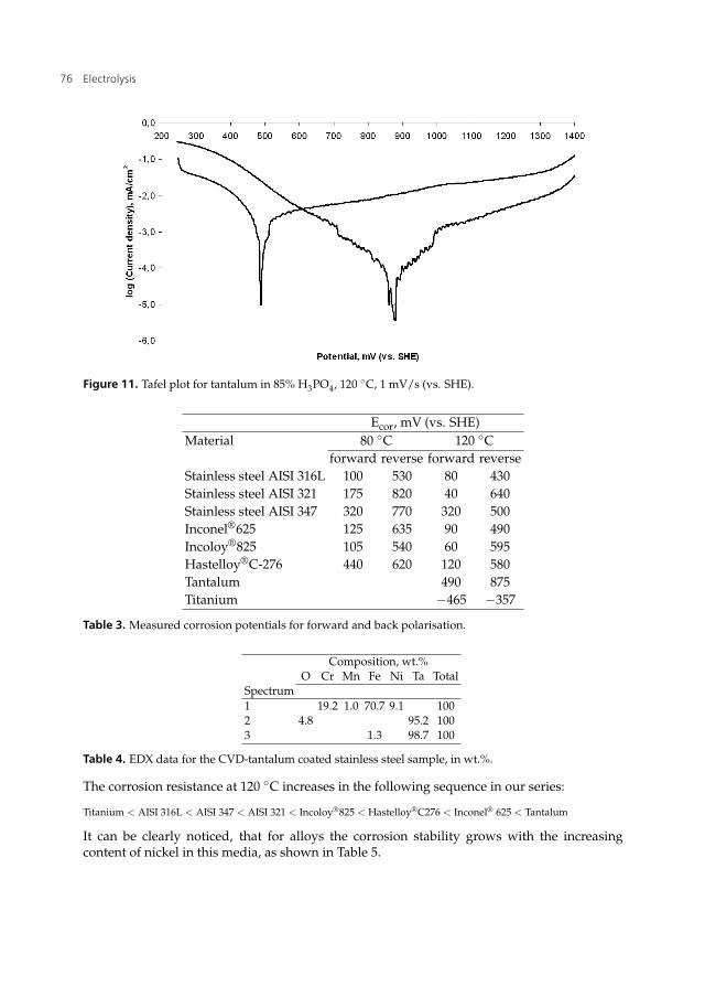
Figure 11. Tafel plot for tantalum in 85% H3PO4, 120 ◦C, 1 mV/s (vs. SHE).
Ecor, mV (vs. SHE)Material 80 ◦C 120 ◦C
forward reverse forward reverseStainless steel AISI 316L 100 530 80 430Stainless steel AISI 321 175 820 40 640Stainless steel AISI 347 320 770 320 500Inconel®625 125 635 90 490Incoloy®825 105 540 60 595Hastelloy®C-276 440 620 120 580Tantalum 490 875Titanium −465 −357
Table 3. Measured corrosion potentials for forward and back polarisation.
Composition, wt.%O Cr Mn Fe Ni Ta Total
Spectrum1 19.2 1.0 70.7 9.1 1002 4.8 95.2 1003 1.3 98.7 100
Table 4. EDX data for the CVD-tantalum coated stainless steel sample, in wt.%.
The corrosion resistance at 120 ◦C increases in the following sequence in our series:
Titanium < AISI 316L < AISI 347 < AISI 321 < Incoloy®825 < Hastelloy®C276 < Inconel® 625 < Tantalum
It can be clearly noticed, that for alloys the corrosion stability grows with the increasingcontent of nickel in this media, as shown in Table 5.
76 Electrolysis

Advanced Construction Materials for High Temperature Steam PEM Electrolysers 17
Figure 12. SEM image of the CVD-tantalum coated stainless steel sample. Numbers refer to EDX pointsand areas measured.
Generally, nickel based alloys show better corrosion stability than austenitic stainless steelsin highly acidic media and elevated temperatures [77]. This tendency is also observed in ourseries.
Nickel’s high degree of corrosion resistance is partly explained by the higher positive standardpotential among the studied alloy compounds. Comparing with less resistant iron, nickelhas 250 mV more positive standard corrosion potential. But compared to pure nickel metal,nickel-chromium-iron-molybdenum alloys show considerably better resistance to corrosionin all inorganic acid solutions [65].
It can also be seen from Table 5, that titanium has a positive effect on the corrosion resistanceof the alloys tested, even though its own resistance is much lower. This effect can be explainedby the EDX data, obtained from AISI 321 and Inconel®625 before and after the electrochemicaltests.
Sample AISI 347 AISI 316L AISI 321 Inconel®625 Incoloy®825 Hastelloy®C-276Ni content, wt.% 9-13 10-13 9-12 62 44 57Ti content, wt.% - - 0.4-0.7 0.4 1.0 -
Table 5. The content of Ni and Ti, in the tested alloys.
It is visible from Figures 13(a) (spectrum 3,4) and 13(b) (spectrum 2,4)and Tables 5(a) and 5(b)that before the corrosion test, Ti is not spread evenly on the surface of AISI 321, it is localized
77Advanced Construction Materials for High Temperature Steam PEM Electrolysers

18 Will-be-set-by-IN-TECH
at definite points, unlike the other elements, distributed more homogeneously. It is safe toassume that points of Ti location are situated on intergranular boundaries. It follows from thedata that the content of titanium in the intergranular region dropped after the electrochemicalexperiment, indicating that corrosion in AISI 321 develops along the intergranular boundariesin this media. Titanium tends to be distributed along these boundaries during the severeanodic attack, thus preventing the formation of chromium carbides in these areas, which couldpromote chromium concentration drop resulting in a loss of passivity in these regions.
(a)
Composition, wt.%, before the electrochemical testsSi Ti Cr Mn Fe Co Ni Total
Spectrum1 0.6 0.3 17.7 1.8 69.8 0.2 9.7 1002 0.5 0.5 18.0 1.4 69.5 0.8 9.4 1003 0.4 27.3 14.5 1.4 49.5 0.5 6.4 1004 0.3 31.2 14.8 1.4 46.6 6.1 100
(b)
Composition, wt.%, after the electrochemical testsSi Ti Cr Mn Fe Co Ni Total
Spectrum1 0.3 0.5 17.7 1.6 70.4 1.0 8.5 1002 0.1 29.2 15.3 1.5 48.5 0.3 5.2 1003 0.5 0.1 18.2 1.2 69.8 1.0 9.2 1004 1.2 9.0 17.5 0.9 62.4 0.6 8.4 100
Table 6. EDX analysis data of AISI 321 before(a) and after(b) the electrochemical tests.
(a) (b)
Figure 13. SEM of AISI 321 before(a) and after(b) the electrochemical tests. Numbers refer to EDX pointsand areas measured.
The same behaviour is observed for another alloy, containing titanium as an addition,protecting the material from intergranular corrosion. Figures 14(a) (spectrum 3,4), 14(spectrum 1,3,5) and Tables 6(a) and 6(b) show SEM and EDX data for Inconel®625. The same
78 Electrolysis

Advanced Construction Materials for High Temperature Steam PEM Electrolysers 19
tendency is even more significant for this alloy. The titanium is distributed irregularly and itscontent decreases after the corrosion experiment.
(a) (b)
Figure 14. SEM of Inconel®625 before(a) and after(b) the electrochemical tests. Numbers refer to EDXpoints and areas measured.
(a)
Composition, wt.%, before the electrochemical testsAl Si Ti Cr Mn Fe Co Ni Nb Mo Total
Spectrum1 0.3 0.3 21.7 0.9 63.1 4.0 10.1 1002 0.3 0.4 0.3 22.1 0.9 0.2 63.4 3.4 9.4 1003 0.1 63.6 5.8 0.1 7.0 23.1 0.6 1004 0.6 0.3 54.9 10.6 0.1 0.3 0.1 18.9 12.2 2.0 100
(b)
Composition, wt.%, after the electrochemical testsAl Si Ti Cr Mn Fe Co Ni Nb Mo Total
Spectrum1 0.5 0.8 20.5 13.7 0.3 0.4 34.9 21.4 7.9 1002 2.2 0.1 15.8 0.5 0.5 40.1 14.0 27.0 1003 0.2 0.1 48.6 12.3 0.0 0.8 24.4 10.0 3.9 1004 0.3 2.1 0.1 13.7 0.7 0.1 0.1 29.4 26.1 27.5 1005 0.1 43.4 11.1 0.4 0.3 21.2 19.8 4.0 100
Table 7. EDX analysis data of Inconel®625 before(a) and after(b) the electrochemical tests.
The discussion above proves the extremely important role of doping the investigated alloyswith titanium in this media, thus protecting them from the most apparent intergranular typeof corrosion.
Molybdenum is more soluble in nickel than in austenitic stainless steels, and higher levels ofalloying are possible with a higher content of nickel. Therefore, the molybdenum content limit
79Advanced Construction Materials for High Temperature Steam PEM Electrolysers

20 Will-be-set-by-IN-TECH
grows with nickel content and high contents of molybdenum are only possible in high nickelalloys [10].
Generally, the addition of molybdenum to stainless steels and alloys is used for enhancedcorrosion resistance. For instance, the addition of even one or two percent of molybdenum toferritic stainless steels significantly increases the corrosion resistance of these material.
Pure nickel-molybdenum alloys, namely alloy B-2, contain approximately 28% molybdenumand and about 1,7% iron. The very high molybdenum content gives excellent resistance toreducing acids, i.e. hydrochloric and sulphuric [20]. For sulphuric acid, this alloy shows goodresistance, even at concentrations close to 90% and temperatures up to 120 ◦C. Non-oxidantconditions, however, must certainly exist in this case. Either the presence of oxygen or aerationwill significantly accelerate corrosion rate [77]. However, the role of molybdenum is notclearly noticed in this series.
4. Conclusions
The corrosion stability of the chosen stainless steels and nickel-based alloys is insufficientfor these materials to be used in HTPEMECs. However, CVD-tantalum coating showedoutstanding stability in the selected media. Therefore, such coatings on the bipolar platesand gas diffusion layers are recommended for long term tests of working HTPEMECs.
Tantalum coated AISI 316L stainless steel and Inconel® 625 are the most suitable materials forbipolar plate in high temperature steam electrolyzers with H3PO4 doped membranes. It hasalso been found that small addition of titanium to the alloys increases the corrosion stabilityin this media. Among austenitic stainless steels, AISI 321 has the lowest corrosion rate.
Anodic passivation with decreased rate of dissolution was observed from the Tafel plotsfor all alloys and metals studied indicating the formation of a protective oxide layer. Thebest corrosion resistance was found for tantalum. The titanium content was found to bean important parameter in the performance of the steels. The accumulation of titanium onthe intergranular boundaries was assumed to inhibit the growth of chromium carbides onthese regions, preventing intergranular corrosion of the samples. However, pure titaniumshowed the poorest resistance to corrosion, accompanied by the lowest corrosion potentialsin the series and highest corrosion currents. Therefore, these facts exclude it as a possiblematerial for use in bipolar plates in high temperature PEM steam electrolyzers, which operateon membranes doped with phosphoric acid.
Acknowledgements
Authors would like to express their gratitude to the Center for renewable hydrogen cycling(HyCycle), Denmark, contract No. 2104-07-0041 and the WELTEMP project under EU SeventhFramework Programme (FP7), grant agreement No. 212903.
Author details
Aleksey Nikiforov, Erik Christensen, Irina Petrushina, Jens Oluf Jensen and Niels J. BjerrumProton Conductors Group, Department of Energy Conversion and Storage, Technical University ofDenmark
80 Electrolysis

Advanced Construction Materials for High Temperature Steam PEM Electrolysers 21
List of Acronyms
AISI American Iron and Steel Institute
ASTM american society for testing and materials
CR corrosion rate
CVD chemical vapour deposition
EDX energy dispersive X-ray spectroscopy
GDL gas diffusion layer
HTPEMEC high temperature PEM electrolyzer cell
HTPEMFC high temperature PEM fuel cell
MEA membrane electrode assembly
OEE oxygen evolution electrode
PBI Poly[2,2’-(m-phenylene)-5,5’-bibenzimidazole
PEM polymer electrolyte membrane
PTFE polytetrafluoroethylene
SEM scanning electron microscopy
SHE standard hydrogen electrode
SOEC solid oxide electrolyzer cell
SPE solid polymer electrolyte
URFC unitized regenerative fuel cells
5. References
[1] Andolfatto, F., Durand, R., Michas, A., Millet, P. & Stevens, P. [1994]. Solid polymerelectrolyte water electrolysis: electrocatalysis and long-term stability, International Journalof Hydrogen Energy 19(5): 421 – 427.
[2] Annual book of ASTM standarts 10.05, G 102-89 (Reapproved 1999), p. 446-452 [n.d.].[3] Annual book of ASTM standarts 10.05, G3-89, p. 42-47 [n.d.].[4] Annual book of ASTM standarts 10.05, G5-94, p. 60-70 [n.d.].[5] Antonucci, V., Di Blasi, A., Baglio, V., Ornelas, R., Matteucci, F., Ledesma-Garcia, J.,
Arriaga, L. G. & Arico, A. S. [2008]. High temperature operation of a compositemembrane-based solid polymer electrolyte water electrolyser, Electrochimica Acta53(24): 7350–7356.
[6] Antunes, R. A., Oliveira, M. C. L., Ett, G. & Ett, V. [2010]. Corrosion of metal bipolar platesfor PEM fuel cells: A review, International Journal of Hydrogen Energy 35(8): 3632–3647.
[7] Appleby, A. & Vandrunen, C. [1975]. The oxygen evolution reaction on rhodium andiridium electrodes in 85% orthophosphoric acid, Journal of Electroanalytical Chemistry60(1): 101–108.
[8] Barbir, F. [2005]. PEM electrolysis for production of hydrogen from renewable energysources, Solar Energy 78(5): 661–669.
[9] Benabdellah, M. & Hammouti, B. [2005]. Corrosion behaviour of steel in concentratedphosphoric acid solutions, Applied Surface Science 252(5): 1657–1661.
81Advanced Construction Materials for High Temperature Steam PEM Electrolysers

22 Will-be-set-by-IN-TECH
[10] Bil’chugov, Y. I., Makarova, N. L. & Nazarov, A. A. [2001]. On limit of molybdenumcontent of pitting-corrosion-resistant austenitic steels, Protection of Metals 37(6): 597–601.
[11] Cardarelli, F., Taxil, P., Savall, A., Comninellis, C., Manoli, G. & Leclerc, O. [1998].Preparation of oxygen evolving electrodes with long service life under extremeconditions, Journal of Applied Electrochemistry 28(3): 245–250.
[12] Carl W. Hamann, Andrew Hamnelt, W. V. [1997]. Electrochemistry, second edn,Wiley-VHC.
[13] Chen, G., Bare, S. R. & Mallouk, T. E. [2002]. Development of supported bifunctionalelectrocatalysts for unitized regenerative fuel cells, Journal of The Electrochemical Society149(8): A1092–A1099.
[14] Chin, D. & Chang, H. H. [1989]. On the conductivity of phosphoric acid electrolyte,Journal of Applied Electrochemistry 19(1): 95–99.
[15] Connolly, D., Longwood & Gresham, W. [1966]. Fluorocarbon vinyl ether polymers.[16] Daghetti, A., Lodi, G. & Trasatti, S. [1983]. Interfacial properties of oxides used as anodes
in the electrochemical technology, Materials Chemistry and Physics 8: 1–90.[17] Di Blasi, A., D’Urso, C., Baglio, V., Antonucci, V., Arico’, A. S., Ornelas, R., Matteucci,
F., Orozco, G., Beltran, D., Meas, Y. & Arriaga, L. G. [2009]. Preparation and evaluationof RuO2 -IrO2, IrO2-Pt and IrO2-Ta2O5 catalysts for the oxygen evolution reaction in anSPE electrolyzer, Journal of Applied Electrochemistry 39(2): 191–196.
[18] Divakar, R., Seshadri, S. G. & Srinivasan, M. [1989]. Electrochemical techniquesfor corrosion rate determination in ceramics, Journal of the American Ceramic Society72(5): 780–784.
[19] Dutta, S. [1990]. Technology assessment of advanced electrolytic hydrogen production,International Journal of Hydrogen Energy 15(6): 379–386.
[20] et. al., A. [1989]. United states patent 4846885.[21] Ghany, N. A. A., Kumagai, N., Meguro, S., Asami, K. & Hashimoto, K. [2002]. Oxygen
evolution anodes composed of anodically deposited mn-mo-fe oxides for seawaterelectrolysis, Electrochimica Acta 48(1): 21 – 28.
[22] Grigoriev, S., Millet, P., Korobtsev, S., Porembskiy, V., Pepic, M., Etievant, C.,Puyenchet, C. & Fateev, V. [2009]. Hydrogen safety aspects related to high-pressurepolymer electrolyte membrane water electrolysis, International Journal of Hydrogen Energy34(14): 5986–5991.
[23] Grigoriev, S., Millet, P., Volobuev, S. & Fateev, V. [2009]. Optimization of porouscurrent collectors for PEM water electrolysers, International Journal of Hydrogen Energy34(11): 4968–4973.
[24] He, R., Li, Q., Xiao, G. & Bjerrum, N. J. [2003]. Proton conductivity of phosphoric aciddoped polybenzimidazole and its composites with inorganic proton conductors, Journalof Membrane Science 226(1-2): 169–184.
[25] Hermann, A., Chaudhuri, T. & Spagnol, P. [2005]. Bipolar plates for PEM fuel cells: Areview, International Journal of Hydrogen Energy 30(12): 1297–1302.
[26] http://hycycle.dk/ [2009]. Hycycle. center for renewable hydrogen cycling.URL: http://hycycle.dk/
[27] http://www.ginerinc.com/ [n.d.].URL: http://www.ginerinc.com/
[28] http://www.hydrogenics.com/ [n.d.].URL: http://www.hydrogenics.com/
82 Electrolysis

Advanced Construction Materials for High Temperature Steam PEM Electrolysers 23
[29] http://www.protonenergy.com [n.d.].URL: http://www.protonenergy.com
[30] http://www.tantaline.com/ [n.d.].URL: http://www.tantaline.com/
[31] Hu, W., Cao, X., Wang, F. & Zhang, Y. [1997]. A novel cathode for alkaline waterelectrolysis, International Journal of Hydrogen Energy 22(6): 621 – 623.
[32] Hung, Y., EL-Khatib, K. M. & Tawfik, H. [2005]. Corrosion-resistant lightweight metallicbipolar plates for PEM fuel cells, Journal of Applied Electrochemistry 35(5): 445–447.
[33] I.Kreysa, G. & Eckermann, R. [1993]. DECHEMA corrosion handbook: corrosive agentsand their interaction with materials, Vol. 12. Chlorinated hydrocarbons-chloroethanes,phosphoric acid, VCH Verlagsgesellschaft, Weinheim (Germany) and VCH Publishers,New York, NY (USA).
[34] International patent application, 03.01.2008, WO 2008/002150 A1, PCT/NO2007/000235[03.01.2008].
[35] Jensen, J., Bandur, V., Bjerrum, N., Højgaard, S., Ebbesen, S. & Mogensen, M. [2008].Pre-investigation of water electrolysis, Technical report.URL: http://130.226.56.153/rispubl/NEI/NEI-DK-5057.pdf
[36] Jensen, J. O., Li, Q. F., Pan, C., Vestbo, A. P., Mortensen, K., Petersen, H. N., Sorensen,C. L., Clausen, T. N., Schramm, J. & Bjerrum, N. J. [2007]. High temperature PEMFCand the possible utilization of the excess heat for fuel processing, International Journal ofHydrogen Energy 32(10-11): 1567–1571.
[37] Joseph, S., McClure, J. C., Chianelli, R., Pich, P. & Sebastian, P. J. [2005]. Conductingpolymer-coated stainless steel bipolar plates for proton exchange membrane fuel cells(PEMFC), International Journal of Hydrogen Energy 30(12): 1339–1344.
[38] Jung, H. Y., Park, S., Ganesan, P. & Popov, B. N. [2008]. Electrochemical studiesof unsupported PtIr electrocatalyst as bifunctional oxygen electrode in unitizedregenerative fuel cell (urfc), Proton Exchange Membrane Fuel Cells 8, Pts 1 and 216(2): 1117–1121.
[39] Keijzer, M., Hemmes, K., VanDerPut, P. J. J. M., DeWit, J. H. W. & Schoonman, J. [1997]. Asearch for suitable coating materials on separator plates for molten carbonate fuel cells,Corrosion Science 39(3): 483–494.
[40] Kouril, M., Christensen, E., Eriksen, S. & Gillesberg, B. [2011]. Corrosion rateof construction materials in hot phosphoric acid with the contribution of anodicpolarization, Materials and Corrosion .
[41] Labou, D., Slavcheva, E., Schnakenberg, U. & Neophytides, S. [2008]. Performance oflaboratory polymer electrolyte membrane hydrogen generator with sputtered iridiumoxide anode, Journal of Power Sources 185(2): 1073–1078.
[42] Lage, L. G., Delgado, P. G. & Kawano, Y. [2004]. Thermal stability and decompositionof Nafion® membranes with different cations using high-resolution thermogravimetry,Journal of Thermal Analysis and Calorimetry 75(2): 521–530.
[43] Lessing, P. A. [2007]. Materials for hydrogen generation via water electrolysis, Journal ofMaterials Science 42(10): 3477–3487.
[44] Li, Q. F., He, R. H., Jensen, J. O. & Bjerrum, N. J. [2003]. Approaches and recentdevelopment of polymer electrolyte membranes for fuel cells operating above 100degrees C, Chemistry of Materials 15(26): 4896–4915.
83Advanced Construction Materials for High Temperature Steam PEM Electrolysers

24 Will-be-set-by-IN-TECH
[45] Li, Q., Jensen, J. O., Savinell, R. F. & Bjerrum, N. J. [2009]. High temperature protonexchange membranes based on polybenzimidazoles for fuel cells, Progress in PolymerScience 34(5): 449–477.
[46] Linkous, C. [1993]. Development of solid polymer electrolytes for water electrolysis atintermediate temperatures, International Journal of Hydrogen Energy 18(8): 641–646.
[47] Linkous, C. A., Anderson, H. R., Kopitzke, R. W. & Nelson, G. L. [1998]. Developmentof new proton exchange membrane electrolytes for water electrolysis at highertemperatures, International Journal of Hydrogen Energy 23(7): 525–529.
[48] Lu, J.-s. [2009]. Corrosion of titanium in phosphoric acid at 250 °C, Transactions ofNonferrous Metals Society of China 19: 552–556.
[49] Lukashenko, T. A. & Tikhonov, K. I. [1998]. Corrosion resistance of a series of groupIV-VI transition metal carbides and nitrides in concentrated solutions of sulfuric andphosphoric acids., Zhurnal Prikladnoi Khimii (Sankt-Peterburg) 71(12): 2017–2020.
[50] Makkus, R. C., Janssen, A. H., de Bruijn, F. A. & Mallant, R. K. [2000]. Use of stainless steelfor cost competitive bipolar plates in the SPFC, Journal of Power Sources 86(1-2): 274–282.
[51] Marshall, A., Børresen, B., Hagen, G., Tsypkin, M. & Tunold, R. [2006]. Electrochemicalcharacterisation of IrxSn1−xO2 powders as oxygen evolution electrocatalysts,Electrochimica Acta 51: 3161–3167.
[52] Marshall, A., Børresen, B., Hagen, G., Tsypkin, M. & Tunold, R. [2007]. Hydrogenproduction by advanced proton exchange membrane (PEM) water electrolysers-reducedenergy consumption by improved electrocatalysis, Energy 32: 431–436.
[53] M.Bengisu [1963]. Engineering Ceramics, Springer-Verlag Berlin Heidelberg 2001.[54] McElroy, J. F. [1994]. Recent advances in SPE® water electrolyzer, Journal of Power
Sources 47(3): 369–375. Proceedings of the Fourth Space Electrochemical Research andTechnology Conference.
[55] Millet, P., Mbemba, N., Grigoriev, S., Fateev, V., Aukauloo, A. & Etiévant, C.[2011]. Electrochemical performances of PEM water electrolysis cells and perspectives,International Journal of Hydrogen Energy 36: 4134–4142.
[56] Millet, P., Ngameni, R. & Grigoriev, S. [2009]. PEM water electrolyszers: Fromelectrocatalysis to stack development, International Journal of Hydrogen Energy 35: 5043– 5052.
[57] Mitsuhashi, A., Asami, K., Kawashima, A. & Hashimoto, K. [1987]. The corrosionbehavior of amorphous nickel base alloys in a hot concentrated phosphoric acid,Corrosion Science 27(9): 957–970.
[58] Ni, M., Leung, M. & Leung, D. [2007]. Energy and exergy analysis of hydrogenproduction by solid oxide steam electrolyzer plant, International Journal of HydrogenEnergy 32(18): 4648–4660.
[59] Nikiforov, A., Petrushina, I., Christensen, E., Tomás-García, A. L. & Bjerrum, N. [2011].Corrosion behaviour of construction materials for high temperature steam electrolysers,International Journal of Hydrogen Energy 36(1): 111–119.
[60] Oberlin R, F. M. [1986]. Status of the membral process for water electrolysis, Hydrogenenergy progress VI, proceedings of the sixth world hydrogen energy conference, Oxford:Pergamon Press pp. 333–40.
[61] Oi, T. & Sakaki, Y. [2004]. Optimum hydrogen generation capacity and current density ofthe pem-type water electrolyzer operated only during the off-peak period of electricitydemand, Journal of Power Sources 129(2): 229 – 237.
84 Electrolysis

Advanced Construction Materials for High Temperature Steam PEM Electrolysers 25
[62] Onoro, J. [2009]. Corrosion fatigue behaviour of 317LN austenitic stainless steel inphosphoric acid, International Journal of Pressure Vessels and Piping 86(10): 656–660.
[63] Pourbaix, M., Klimzack-Mathieiu, L., Mertens, C., Meunier, J., Vanleugenhaghe, C.,de Munck, L., Laureys, J., Neelemans, L. & Warzee, M. [1963]. Potentiokinetic andcorrosimetric investigations of the corrosion behaviour of alloy steels, Corrosion Science3(4): 239–259.
[64] Robin, A. & Rosa, J. L. [2000]. Corrosion behavior of niobium, tantalum and their alloys inhot hydrochloric and phosphoric acid solutions, International Journal of Refractory Metalsand Hard Materials 18: 13–21.
[65] Rockel, M. [1998]. Corrosion behaviour of nickel alloys and high-alloy stainless steel, NickelAlloys, Marcel Dekker Inc, New York.
[66] Shin, Y., Park, W., Chang, J. & Park, J. [2007]. Evaluation of the high temperatureelectrolysis of steam to produce hydrogen, International Journal of Hydrogen Energy32(10-11): 1486–1491.
[67] Song, S. D., Zhang, H. M., Ma, X. P., Shao, Z. G., Zhang, Y. N. & Yi, B. L. [2006].Bifunctional oxygen electrode with corrosion-resistive gas diffusion layer for unitizedregenerative fuel cell, Electrochemistry Communications 8(3): 399–405. ElectrochemistryCommunications.
[68] Song, S., Zhang, H., Ma, X., Shao, Z., Baker, R. T. & Yi, B. [2008]. Electrochemicalinvestigation of electrocatalysts for the oxygen evolution reaction in PEM waterelectrolyzers, International Journal of Hydrogen Energy 33: 4955–4961.
[69] Suffredini, H. B., Cerne, J. L., Crnkovic, F. C., Machado, S. A. S. & Avaca, L. A. [2000].Recent developments in electrode materials for water electrolysis, International Journal ofHydrogen Energy 25(5): 415–423.
[70] Swette, L. L., LaConti, A. B. & McCatty, S. A. [1994]. Proton-exchange membraneregenerative fuel cells, Journal of Power Sources 47(3): 343–351.
[71] Tawfik, H., Hung, Y. & Mahajan, D. [2007]. Metal bipolar plates for PEM fuel cell-Areview, Journal of Power Sources 163(2): 755–767.
[72] Tian, R. J., Sun, J. C. & Wang, L. [2006]. Plasma-nitrided austenitic stainless steel 316L asbipolar plate for PEMFC, International Journal of Hydrogen Energy 31(13): 1874–1878.
[73] Trasatti, S. [1980]. Electrodes of conductive metallic oxides, Studies in physical andtheoretical chemistry, Elsevier, 335 Jan van Galenstraat P.O. Box 211, 1000 AEAmsterdam, The Netherlands.
[74] Trethewey, K. R. & Chamberlain, J. [1988]. Corrosion, Longman Group UK Limited.[75] Turner, J., Sverdrup, G., Mann, M. K., Maness, P., Kroposki, B., Ghirardi, M., Evans,
R. J. & Blake, D. [2008]. Renewable hydrogen production, International Journal of EnergyResearch 32(5): 379–407.
[76] Wang, Y. & Northwood, D. O. [2007]. An investigation of the electrochemical propertiesof PVD TiN-coated SS410 in simulated PEM fuel cell environments, International Journalof Hydrogen Energy 32(7): 895–902.
[77] W.Z.Friend [1980]. Corrosion of Nickel and Nickel-Base Alloys, J.Wiley&Sons, NewYork-Chichester-Brisbane-Toronto.
[78] Yamaguchi, M., Okisawa, K. & Nakanori, T. [1997]. Development of high performancesolid polymer electrolyte water electrolyzer in WE-NET, Proceedings of the IntersocietyEnergy Conversion Engineering Conference 3-4: 1958–1961.
85Advanced Construction Materials for High Temperature Steam PEM Electrolysers

26 Will-be-set-by-IN-TECH
[79] Zhang, Y., Zhang, H., Ma, Y., Cheng, J., Zhong, H., Song, S. & Ma, H. [2009]. A novelbifunctional electrocatalyst for unitized regenerative fuel cell, Journal of Power Sources195: 142–145.
86 Electrolysis