advanced computer networks - · advanced computer networks 263‐3501‐00 datacenter network...
TRANSCRIPT

Monday 22 April 2013
Advanced Computer Networks263‐3501‐00
Datacenter Network Fabric
Patrick Stuedi
Spring Semester 2013
© Oriana Riva, Department of Computer Science | ETH Zürich

Monday 22 April 2013
Last week
IP Anycast
Dynamic DNS Located nearby data center
Loadbalancing with L3 switching
TCP splicing
L7 Switching

Monday 22 April 2013
Course Overview
covered in basic ETH “Operating Systems and
Networks” course
Wireless networking technologies: first half of this course
Datacenter networking:
second half of this course
We are now here
Monday 22 April 2013
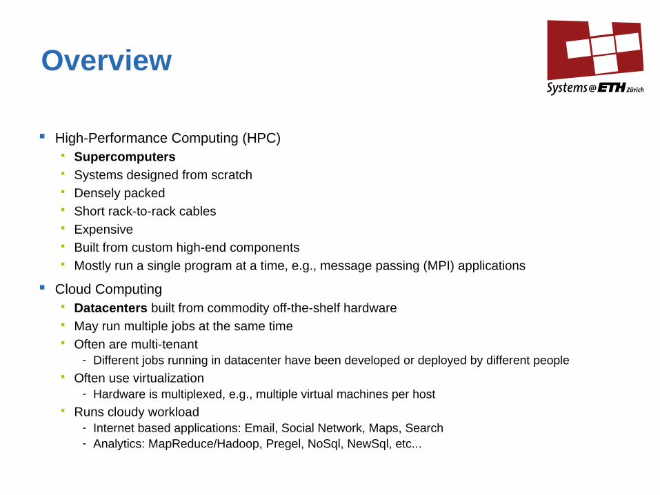
Overview
High-Performance Computing (HPC) Supercomputers Systems designed from scratch Densely packed Short rack-to-rack cables Expensive Built from custom high-end components Mostly run a single program at a time, e.g., message passing (MPI) applications
Cloud Computing Datacenters built from commodity off-the-shelf hardware May run multiple jobs at the same time Often are multi-tenant
- Different jobs running in datacenter have been developed or deployed by different people Often use virtualization
- Hardware is multiplexed, e.g., multiple virtual machines per host Runs cloudy workload
- Internet based applications: Email, Social Network, Maps, Search- Analytics: MapReduce/Hadoop, Pregel, NoSql, NewSql, etc...
Monday 22 April 2013
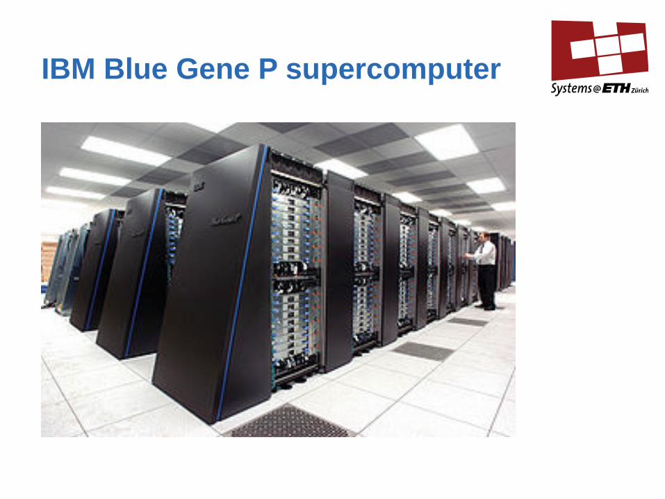
IBM Blue Gene P supercomputer

Monday 22 April 2013
Blue Gene: Cabling

Monday 22 April 2013
Blue Gene Supercomputer Overview
Blue Gene is a family of supercomputers from IBM BlueGene/L (2004) BlueGene/P (2006) BlueGene/Q (2010)
Blue Gene/L: 64K-node highly integrated supercomputer Many of the components (processor, network, router) on the
same chip
Blue Gene/L: #1 Supercomputer as ranked by Top500 list from November 2004 – June 2008
Monday 22 April 2013
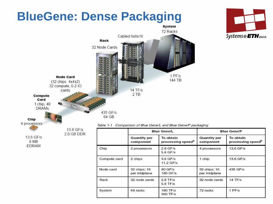
BlueGene: Dense Packaging

Monday 22 April 2013
Design Motivation: Processor Clock Frequency Scaling Ends
Three decades of exponential clock rate (and electrical power!) growth has ended
Yet Moore’s Law continues in transistor count
What do we do with all those transistors to keep performance increasing to meet demand?
Industry response: Multi-core (i.e. double the number of cores every 18 months instead of the clock frequency (and power!)
But, added transistors can be used for other functions such as memory/storage controllers, embedded networks, etc.Source: “The Landscape of Computer Architecture,” John Shalf,
NERSC/LBNL, presented at ISC07, Dresden, June 25, 2007

Monday 22 April 2013
Blue Gene/P System-on-a-Chip Compute NodeNetwork logic is a fraction of compute ASIC complexity/area.
BG/P Node Card

Monday 22 April 2013
Data Centers and the Future Internet
With the emergence of cloud computing high performance networking is
increasingly happening inside commodity datacenters 99% of compute, storage, communication will be inside the data center
Applications and data will be partitioned and replicated across multiple data
centers
Commodity datacenters run traditional HPC workload Example: Amazon cluster ranked 42 in Top500 list on November 2011
Some technologies from Supercomputer trickle into datacenters Network topologies (e.g., FatTree)
Supercomputing technologies get commodotized 10 GbE, 10 GbE

Monday 22 April 2013
Modern Facebook Datacenter,Prineville, USA
Monday 22 April 2013
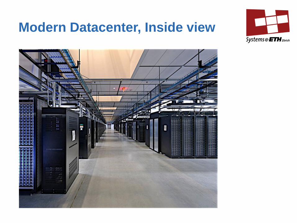
Modern Datacenter, Inside view

Monday 22 April 2013
High-Performance Networking:Outlook
Network topologies Mesh, Torus, Tree
Data link layer and switching fabric Lossy and lossless data link layer Ethernet, Infiniband
Addressing, Configuration, Routing MAC and IP address configuration ARP
Transport layer Datacenter TCP TCP offloading Incast Problem
End-host interfaces RDMA
Monday 22 April 2013
Network Topology: Basics
Topologies can be classified into:
Direct networks Processing nodes directly attached to the switching fabric
Indirect networks: separate processing nodes and switching elements
In direct networks nodes often have very few ports (2,3,4, …) Low port networks are also called low-radix networks
Elements (e.g. switches) in indirect networks often have higher port numbers (16,32,64,128,...) High port networks are also called high-radix networks

Monday 22 April 2013
Criteria for choosing a particular network topology
Worst case diameter: largest path between two nodes The more hops the bigger the latency The more hops the more congestion in the network
Cost
Bisectional bandwidth- The rate at which communication can take place between one
half of a cluster and the other- Typically the segmentation refers to the worst-case
segmentation
Path redundency Multiple paths between src/dst nodes Affects reliability, bandwidth, etc

Monday 22 April 2013
Direct Networks: Mesh, Torus, Hypercube
Notation <k>-ary-<n>-mesh or <k>-ary-<n>-torus k: radix, number of elements in each dimension
(different meaning here than in term “high-radix-network”) n: number of dimensions radix k does not have to be the same in each dimension
Examples:a) 10-ary 1-torus
b) 5-ary 2-torus
c) 3-ary 3-torus

Monday 22 April 2013
Direct Networks: Mesh, Torus, Hypercube (2)
Cost effective at scale Allows for very dense packaging (single node card with
compute element and switching element)
Great performance for applications with locality Computation has dependencies on results of computations on
neighboring nodes (many MPI application have this property)
Simple expansion for future growth Just append nodes on one of the dimensions
Good path redundancy

Monday 22 April 2013
Example Bisection Bandwidth
Bisection bandwidth: Minimal #arcs to be removed to partition the network in two equal halves 4-ary-2-mesh: bisection bandwidth 4 2-ary-3-mesh: bisection bandwidth 4

Monday 22 April 2013
Example: IBM Blue Gene 3D Torus Network
Interconnects compute nodes Communication backbone for
computation
In BlueGene/L: 32x32x64 connectivity Worst case diameter:
16+16+32 = 64 hops 0.5 us latency to nearest neighbors 5 us latency to farthest neighbors Different consecutive packets can
follow different routes

Monday 22 April 2013
Indirect Networks
Datacenters typically deploy indirect networks Based on commodity switches Separate compute nodes
Data Center Network Design Goals Scalable interconnection bandwidth
- Full bisection bandwidth (aggregate bandwidth = #hosts * host NIC capacity)
Performance isolation- Traffic of one service should not be affected by traffic of any other service
Ease of management- Assign and migrate any virtual machine to any physical host- Avoid managing 100-1000 network elements
Economies of scale- Price/port constant with the number of hosts

Monday 22 April 2013
Indirect Network: Common 3-Tier Datacenter Tree

Monday 22 April 2013
Datacenter Networks (2)
A rack has ~20-40 servers
Example of a TOR switch with 48 ports

Monday 22 April 2013
Example Configuration
Data center with 11'520 machines
Machines organized in racks and rows Data center with 24 rows Each row with 12 racks Each rack with 40 blades
Machines in a rack interconnected with a ToR switch (DC access layer) ToR Switch with 48 GbE ports and 4 10GigE uplinks
ToR switches connect to End-of-Row (EoR) switches via 1-4 10GigE uplinks (DC
aggregation layer) For fault-tolerance ToR might be connected to EoR switches of different rows
EoR switches typically 10GbE To support 12 ToR switches EoR would have to have 96 ports (4*12*2)
Core Switch layer 12 10GigE switches with 96 ports each (24*48 ports)

Monday 22 April 2013
Over-subscription
High port switches are expensive (cost increasing non-linear with the number of ports)
Many data center designs introduce oversubscription as a means to lower the total cost of the design
Oversubscription ratio of a switch: Ratio of ports facing downwards vs. ratio of ports (with equal bandwidth
ports)
Switch up-links get heavily loaded Poor bisection bandwidth
Oversubscription of 1:1 for full 10GbE data center with common 3-tier network topology currently not possible Switches are not fast enough to switch 10GbE with high port counts
Monday 22 April 2013
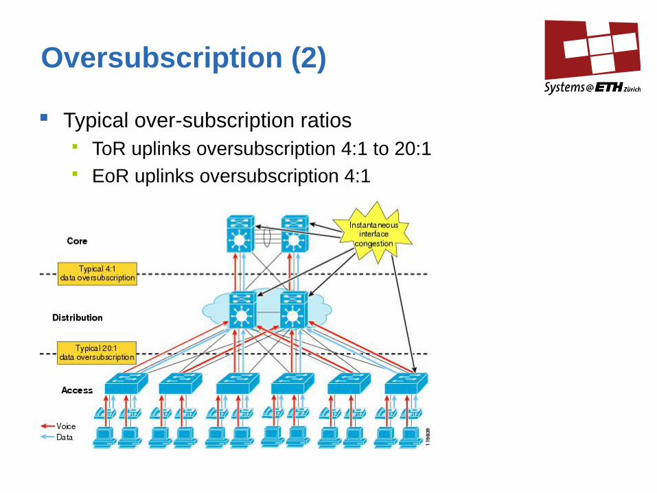
Oversubscription (2)
Typical over-subscription ratios ToR uplinks oversubscription 4:1 to 20:1 EoR uplinks oversubscription 4:1

Monday 22 April 2013
Problem 1: Over-subscription (2)
Cost estimate vs. maximum possible number of hosts for different over-subscription ratios (2008)

Monday 22 April 2013
Indirect Network: Fat-Tree Network
Idea: links become "fatter" as one moves up the tree towards the root
Example: binary fat tree
By judiciously choosing the “fatness”, a Fat-Tree network can provide full bisection bandwidth Or a oversubscription ratio of 1:1
Fat-Tree offers redundant paths (!)
Portland: Datacenter network architecture proposed by Research Group at UC San Diego Fat-Tree built from commodity switches

Monday 22 April 2013
Portland: A Scalable Fault-Tolerant Layer 2 Data Center Network Fabric
Example: 16 port network Built from identical 4 port switches, 16 hosts organized into pods Each pod is a 2-ary 2-tree Full bandwidth between hosts directly connected to a pod (4 links into pod, 4 links within
pod) Full bandwidth between any host pair (16 links at edge-aggregation, 16 links
aggregation-core

Monday 22 April 2013
Fat-tree Scaling
K-ary fat-tree
K pods each containing two layers of k/2 switches Each k-port switch in edge layer (access layer) uses k/2 ports to
connect to hosts and k/2 ports to connect to aggregation switches
(K/2)^2 core switches Port (i) of any core switch connects to pod (I)
Fat-tree built from 48-port switches supports (k^3)/4 hosts 27,648 hosts Cost: 8.64M as compared to 37M for traditional topology (2008)
Approach scales to 10GbE at the Edge (!)

Monday 22 April 2013
High-Performance Networking:Outlook
Network topologies Mesh, Torus, Tree
Data link layer and switching fabric Ethernet, Infiniband Lossy and lossless data link layer
Addressing, Configuration, Routing MAC and IP address configuration ARP
Transport layer Datacenter TCP TCP offloading Incast Problem
End-host interfaces RDMA

Monday 22 April 2013
High Performance Neworking: Layer-2 / Interconnect technologies
Supercomputer interconnect technologies through the ages: Ten years ago (2002)
- Many different interconnect technologies
- Myrinet takes about 30%
In 2010:- Gigabit Ethernet takes 50%- Infiniband 41 %
Datacenter interconnects Almost entirely Ethernet

Monday 22 April 2013
Infiniband vs Ethernet
Infiniband (IB) Low latency
- ~ 1us for two directly connected boxes High bandwidth
- For data rates (SDR: 10 Gbit/s, DDR: 20 Gbit/s, QDR: 40 Gbit/s) Supports RDMA interface
- RDMA: Remote Direct Memory Access: No OS involvement during transmission and reception of packets (see next week)
Ethernet: 10GbE has 5-6 times the latency of Infiniband 40GbE and 100Gbe in the pipeline
Both IB and Ethernet can be operated with a switched fabric topology

Monday 22 April 2013
Scaling Ethernet in Datacenters
Ethernet is the primary network technology for data centers High link bandwidth at comparably low cost Self-configuration (Spanning Tree Protocol)
Outside of large data centers most networks are designed as
several modest-sized Ethernets (IP subnets), connected by one or two layers of IP routes
But datacenter operaters want Ethernet to scale to an entire datacenter, for several reasons: The use of IP subnets creates significant management
complexity (DHCP configuration, etc.) The use of IP makes VM migration more difficult (requires VM to
change its IP address to match the new subnet)

Monday 22 April 2013
Why Ethernet is hard to scale
Ethernet Spanning Tree protocol is not designed for large datacenters Does not leverage multipath if available Spanning tree allows only one path between any src/dst pair
- Limits bandwidth- Low reliability
Packet floods Switches discover hosts and creating routing entry Switches must forget table entries periodically to support host mobility Switch receiving a packet for unknown host will flood the packet on all ports
Switch state Can become large if the entire datacenter is one layer-2 network

Monday 22 April 2013
Switch State: Is it a problem?(Flat vs hierarchical addressing)
Commodity switches today have ~640KB of low-latency, power hungry, expensive on-chip memory 32-64K flow entries
10 million virtual endpoints in 500k servers in data center
Flat addresses: 10 million address mappings → ~ 100MB on chip memory → ~150 times the memory size that can be put on chip today
Hierarchical addresses: 100-1000 address mappings → ~10KB of memory → easily accommodated by commodity switches
Monday 22 April 2013
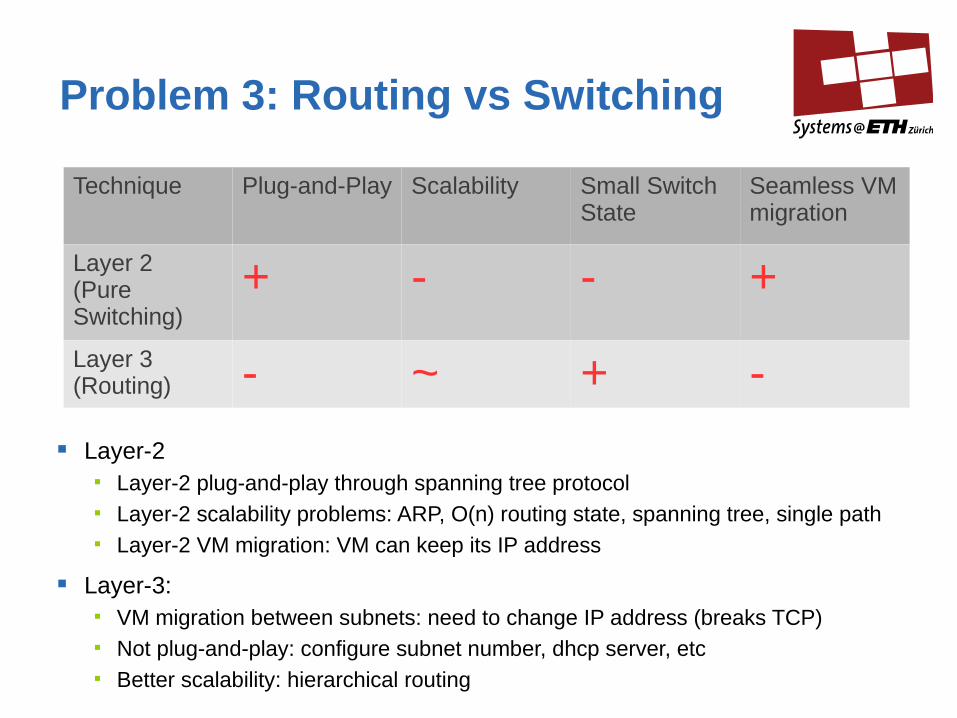
Problem 3: Routing vs Switching
Technique Plug-and-Play Scalability Small Switch State
Seamless VM migration
Layer 2(Pure Switching)
+ - - +
Layer 3(Routing) - ~ + -
Layer-2 Layer-2 plug-and-play through spanning tree protocol Layer-2 scalability problems: ARP, O(n) routing state, spanning tree, single path Layer-2 VM migration: VM can keep its IP address
Layer-3: VM migration between subnets: need to change IP address (breaks TCP) Not plug-and-play: configure subnet number, dhcp server, etc Better scalability: hierarchical routing

Monday 22 April 2013
Scaling Ethernet in Portland
Portland: Research at Data Center Network Group, UC San Diego
Single layer-2 network with up to 100K ports 1M endpoints (through virtualization) VM migration while keeping IP address
Minimize amount of switch state
Towards zero-configuration No subnet or hierarchical IP addresses, dhcp etc.
First-class support for multi-path routing
Uses a Fat-Tree Topology as shown in slide 32
Monday 22 April 2013
Scaling Ethernet in Portland:Key principles
Host IP address: Node identifier, fixed even after VM migration
Pseudo MAC: node location In-network rewriting of MAC address PMAC address changes depending on location of host PMAC address encodes location of host PMAC used to do routing
Fabric Manager: centralized lookup service Maintains IP->PMAC mappings Replaces ARP Lookup is unicast instead of broadcast

Monday 22 April 2013
PMAC format
PMAC: pod.position.port.vmid
0 1 0 1 0 1 0 1

Monday 22 April 2013
Autoconfiguration of PMACs at Switches
Location Discovery Messages (LDM) exchanged between neighboring switches Discovery at bootup
LDM protocol helps switches to learn Tree level (edge, aggregation, core) Pod number Position number
Configuration does not involve broadcast

Monday 22 April 2013
Autoconfiguration: Tree-level
I am an edge switch (ES) if I receive LDM message on my uplink only
Aggregation switches (AS) get messages from ES as well as from unknown
switches
Core switches get messages on all ports from AS
ES
AS
CS

Monday 22 April 2013
Autoconfiguration: Position number
Run agreement protocol: propose random position number
Use aggregation switches to ensure no two edge switches are assigned the same position number

Monday 22 April 2013
Autoconfiguration: Pod number
Use directory service to get the pod number
fabricmanager
0

Monday 22 April 2013
PMAC Example
Switch communicates constructed PMAC for hosts to Fabric
manager

Monday 22 April 2013
Proxy ARP
Edge switches Intercept ARP requests, contacts fabric manager
ARP reply contains PMAC

Monday 22 April 2013
Portland Routing
Since PMAC encode the location of a host each switch can, based on PMAC, decide to Route packet to aggregation switch if in the same POD Route upwards if in a different POD
Multipath through ECMP Equal-cost multi-path routing Loadbalancing: hash flows/packets to paths

Monday 22 April 2013
VL2: A Scalable and Flexible Data Center Architecture
Alternative datacenter architecture to Portland Portland is network-centric: intelligence in switches VL2 is end server-centric: intelligence in servers By Microsoft Research
Key ideas of VL2:
VL2 agent on each server intercepting ARP Mapping of location independent IP address (AA)
to location dependent IP address (LA)
Routing: Lookup of LA of switch which serves the dst node Tunnel application packet to switch using the LA of the switch
VL2 shares concepts with Portland: Fat-Tree, Directory Server, ECMP

Monday 22 April 2013
VL2 Example
Each AA is has an associated LA (LA of ToR Switch), mapping stored in VL2 Directory
Routing: Server traps packet and encapsulates it with the LA address of the ToR of the destination
Load balancing: Source ToR encapsulates packet to a randomly chosen intermediate switch
Monday 22 April 2013
References
“High Performance Datacenter Networks: Architecture, Algorithms, and Opportunities”, Synthesis Lectures on Computer Architecture, Morgan & Claypool, 2010
“An Overview of the BlueGene/L Supercomputer”, The BlueGene/L Team, 2002
SPAIN: COTS Data-Center Ethernet for Multipathing over Arbitrary Topologies, NSDI 2010
Portland: A Scalable Fault-Tolerant Layer 2 Data Center Network Fabric, Sigcomm 2009
“A Guided Tour of Data Center Networking”, Dennis Abts and Bob Fielderman, ACM QUEUE, June 2012