advanced composite materials in new england’s ...transctr/pdf/netc/netcr98_09-3.pdf · i advanced...
TRANSCRIPT

i
Advanced Composite Materials in New England’s Transportation Infrastructure:
Design, Fabrication, and Installation of ACM Bridge Drain System
Dr. Roberto A. Lopez-Anido, PI
Keenan Goslin, P.E, Co-PI
Prepared for: The New England Transportation Consortium
August 8, 2016
NETCR98 Project No. 09-03
“This report, prepared in cooperation with the New England Transportation Consortium, does not constitute a standard, specification, or regulation. The contents of this report reflect the views of the author(s) who is (are) responsible for the facts and the accuracy of the data presented herein. The contents do not necessarily reflect the views of the New England Transportation Consortium or the Federal Highway Administration.”

ii
ACKNOWLEDGEMENTS
The following are the members of the Technical Committee that developed the scope of work for the project and provided technical oversight throughout the course of the research:
Dale Peabody, Maine Department of Transportation, Chairperson Kevin Daigle, New Hampshire Department of Transportation
Alireza Jamalipour, Connecticut Department of Transportation Christopher Mooney, Vermont Agency of Transportation
Michael Wight, Maine Department of Transportation

iii
Technical Report Documentation Page
1. Report No. 2. Government Accession No.N /A
3. Recipient's Catalog No.N /A
4. Title and SubtitleAdvanced Composite Materials in New England’s
Transportation Infrastructure: Design, Fabrication, and Installation of ACM Bridge Drain System
5. Report DateAugust 8, 2016
6. Performing Organization CodeN /A
7. Author(s)Roberto A. Lopez-Anido and Keenan Goslin 8. Performing Organization Report No.
NETCR989. Performing Organization Name and Address
Advanced Structures and Composites CenterUniversity of Maine35 Flagstaff Road, Orono, ME, 04469
10. Work Unit No. (TRAIS)N /A
11. Contract or Grant No.N/A
12. Sponsoring Agency Name and Address
New England Transportation ConsortiumC/O Transportation Research CenterUniversity of Vermont, Farrell Hall210 Colchester Ave.Burlington, Vt, 05405
13. Type of Report and Period CoveredFinal Report
14. Sponsoring Agency Code
NETC 09-03 A study conducted incooperation with the U.S. DOT
15. Supplementary NotesN/A
16. Abstract
The project report presents the design and fabrication of a standard fiber-reinforced polymer (FRP) compositedrain that can be produced economically for use throughout New England bridges. The installation of the fabricated drain system in representative bridge applications in New England is documented to provide information on its performance, and ease of construction. The major obstacles or gaps for the implementation of FRP drains in highway bridges are the lack of material, fabrication and installation specifications, the unavailability of standard designs, and the unknown performance during service. The proposed standard FRP drain system can be used both for new construction and rehabilitation projects. The following activities were conducted to address the current gaps, and design, fabricate and install the standard FRP composite drain: 1) Establish specific performance requirements for FRP composite drains for highway bridges; 2) Draft standard specifications for FRP drains in bridge applications; 3) Identify and contact qualified composite manufacturers to get input on the standard practice for fabrication and installation of FRP drains; and 4) Identify representative bridges to demonstrate and document the FRP drain installation methods.
17. Key Words
FIBER REINFORCED POLYMER, DRAIN,FRP, COMPOSITE, BRIDGE, SPECIFICATIONS
18. Distribution Statement
No restriction. This document is available to thepublic from the sponsoring agency at the websitehttp://www.cflhd.gov.
19. Security Classif. (of this report)Unclassified
20. Security Classif. (of this page)Unclassified
21. No. of Pages57
22. PriceN /A
Form DOT F 1700.7 (8-72) Reproduction of completed page authorized
NETCR98

iv
SI* (MODERN METRIC) CONVERSION FACTORS APPROXIMATE CONVERSIONS TO SI UNITS
SYMBOL WHEN YOU KNOW MULTIPLY BY TO FIND SYMBOL LENGTH
in inches 25.4 millimeters mm ft feet 0.305 meters m yd yards 0.914 meters m mi miles 1.61 kilometers km
AREA in2 square inches 645.2 square millimeters mm2 ft2 square feet 0.093 square meters m2 yd2 square yard 0.836 square meters m2 ac acres 0.405 hectares ha mi2 square miles 2.59 square kilometers km2
VOLUME fl oz fluid ounces 29.57 milliliters mL gal gallons 3.785 liters L ft3 cubic feet 0.028 cubic meters m3
yd3 cubic yards 0.765 cubic meters m3
NOTE: volumes greater than 1000 L shall be shown in m3 MASS
oz ounces 28.35 grams g lb pounds 0.454 kilograms kg T short tons (2000 lb) 0.907 megagrams (or "metric ton") Mg (or "t")
TEMPERATURE (exact degrees) oF Fahrenheit 5 (F-32)/9 Celsius oC
or (F-32)/1.8 ILLUMINATION
fc foot-candles 10.76 lux lx fl foot-Lamberts 3.426 candela/m2 cd/m2
FORCE and PRESSURE or STRESS lbf poundforce 4.45 newtons N lbf/in2 poundforce per square inch 6.89 kilopascals kPa
APPROXIMATE CONVERSIONS FROM SI UNITS SYMBOL WHEN YOU KNOW MULTIPLY BY TO FIND SYMBOL
LENGTH mm millimeters 0.039 inches in m meters 3.28 feet ft m meters 1.09 yards yd km kilometers 0.621 miles mi
AREA mm2 square millimeters 0.0016 square inches in2
m2 square meters 10.764 square feet ft2
m2 square meters 1.195 square yards yd2
ha hectares 2.47 acres ac km2 square kilometers 0.386 square miles mi2
VOLUME mL milliliters 0.034 fluid ounces fl oz L liters 0.264 gallons gal m3 cubic meters 35.314 cubic feet ft3
m3 cubic meters 1.307 cubic yards yd3
MASS g grams 0.035 ounces oz kg kilograms 2.202 pounds lb Mg (or "t") megagrams (or "metric ton") 1.103 short tons (2000 lb) T
TEMPERATURE (exact degrees) oC Celsius 1.8C+32 Fahrenheit oF
ILLUMINATION lx lux 0.0929 foot-candles fc cd/m2 candela/m2 0.2919 foot-Lamberts fl
FORCE and PRESSURE or STRESS N newtons 0.225 poundforce lbf kPa kilopascals 0.145 poundforce per square inch lbf/in2
*SI is the symbol for the International System of Units. Appropriate rounding should be made to comply with Section 4 of ASTM E380.(Revised March 2003) ii
1
Advanced Composite Materials in New England’s Transportation Infrastructure:
Design, Fabrication, and Installation of ACM Bridge Drain System
Dr. Roberto A. Lopez-Anido, PI Keenan Goslin, P.E, Co-PI
University of Maine’s Advanced Structures and Composites Center Report Number: 17-3-1202
AbstractThe project report presents the design and fabrication of a standard fiber-reinforced polymer (FRP) composite drain that can be produced economically for use throughout New England bridges. The installation of the fabricated drain system in representative bridge applications in New England is documented to provide information on its performance, and ease of construction. The major obstacles or gaps for the implementation of FRP drains in highway bridges are the lack of material, fabrication and installation specifications, the unavailability of standard designs, and the unknown performance during service. The proposed standard FRP drain system can be used both for new construction and rehabilitation projects. The following activities were conducted to address the current gaps, and design, fabricate and install the standard FRP composite drain: 1) Establish specific performance requirements for FRP composite drains for highway bridges; 2) Draft standard specifications for FRP drains in bridge applications; 3) Identify and contact qualified composite manufacturers to get input on the standard practice for fabrication and installation of FRP drains; and 4) Identify representative bridges to demonstrate and document the FRP drain installation methods.
This report shall not be reproduced, except in full, without the written approval of University of Maine’s Advanced Structures and Composites Center.
The University of Maine Advanced Structures and Composites Center is an ISO 17025 accredited testing laboratory, accredited by the International Accreditation Service.

2
TableofContents
Introduction...........................................................................................................................3ResearchProblemStatement...........................................................................................................3Objectives........................................................................................................................................5ReportOrganization.........................................................................................................................6References.......................................................................................................................................7
Task1-ReviewoftypicalbridgedraindetailsthatarerepresentativeinNewEngland...........8SummaryofNETC-DOTBridgeDrainPhysicalDesignParameters.....................................................8
Task2–Developmentofstandarddrainrequirementsfornewandrehabilitationprojects..10CriteriaforBaselineMechanicalPropertiesandDurabilityRequirements......................................10FRPCompositeBridgeDrainComponentsSpecification.................................................................12AppendixA:FRPcompositedrainandpipematerialrequirements................................................18AppendixB:Preferredinlet/scuppersizesandoverallgeometries.................................................24AppendixC:SpecialprovisionforFRPBridgeDrainsfortheHowland-EnfieldBridge,Maine..........26
Task3-SelectionofparticipatingFRPdrainsuppliers..........................................................31SupplierA:KenwayCorporation....................................................................................................32SupplierB:FRPBridgeDrainPipe-WestfallCompany.....................................................................33
Task4:QualificationofFRPdrainsuppliersthroughmaterialtesting....................................34SupplierA:KenwayCorporation....................................................................................................35SupplierB:FRPBridgeDrainPipe-WestfallCompany.....................................................................38
Task5:DocumentationofinstallationofFRPdrainsinbridges.............................................41UnionStreetBridge,Bangor,Maine...............................................................................................41Richmond-DresdenBridge,Maine..................................................................................................49
Summary..............................................................................................................................53

3
INTRODUCTION
RESEARCH PROBLEM STATEMENT
Advanced composite materials (ACM), also known as fiber-reinforced polymer (FRP) composites, have increasingly been used in bridge applications. FRP composites have been used in the rehabilitation and retrofit of beams, columns and decks. FRP composites are corrosion resistant and lightweight materials, which can be manufactured using different processes. The properties of FRP composites can be optimized for particular structural applications by selecting the type and orientation of fiber reinforcement and the polymer matrix. For these reasons FRP composites have the potential to be a cost-effective and durable solution for specific applications in the transportation infrastructure.
The New England Transportation Consortium (NETC) has conducted two research projects to date to identify those applications within the transportation infrastructure in New England where FRP composites could replace traditional materials used in civil engineering. The primary objective of NETC 01-1 was to identity obstacles for the widespread adoption of FRP composites in New England’s transportation infrastructure with the goal of promoting its implementation (Breña et al. 2006).
The second project, NETC 01-1-T2: Phase I, was conducted to identify and select an application for which FRP composites offered a cost-effective alternative to conventional construction materials. The goal was to select a prototype application that could be competitively fabricated and installed in the transportation infrastructure throughout New England. A standard drain system that could be used throughout bridges in New England to eliminate the problems with corrosion and leakage that occurs when using traditional materials, and to extend the service life of bridge drains was selected (Breña and Civjan 2009).
Composite bridge components, such as FRP bridge drains, can be very valuable in extending the life of bridges by preventing corrosion damage. FRP bridge drains is one of the areas where MaineDOT has used composites to extend service life (MaineDOT 2014).
The FHWA Hydraulics Engineering Circular No. 2 provides a manual on design of bridge deck drainage (FHWA-HEC 21 1993). This manual is a compendium of bridge drainage design guidance, which provides guidelines and procedures for designing bridge deck drainage systems, including illustrative examples. The manual emphasizes the use of the most hydraulically efficient and maintenance-free drain systems. The manual also presents the advantages of designing to minimize the complexity of bridge deck drainage systems and discusses the integration of practical drainage details into overall structural design. Drainage system design is approached from the viewpoints of hydraulic capacity, traffic safety, structural integrity, practical maintenance, and architectural aesthetics. System hardware components, such as inlets, pipes, and downspouts, are described.
Conventional steel drainage systems used in concrete bridge decks are typically corroded by deicing chemicals and clogged by debris. The University of Maine (UMaine) in collaboration with Maine Department of Transportation (MaineDOT) and Kenway Corporation designed, prototyped and tested and FRP composite drain, grating and downspout system to replace corroded steel drains in three bridges. Three identical prototypes were fabricated, embedded in concrete slabs, and submitted to a series of laboratory tests to ensure structural integrity and to

4
optimize the design for long-term durability. The tests included an ice formation study, compression loading tests based on the AASHTO HS25 wheel load specification, 100,000 cycle fatigue tests, ultimate compression tests, and reverse push-out tests. The prototype proved to be acceptable for rehabilitation of highway bridges. The prototype design was improved and approved as a safe, functional, and durable drain system by MaineDOT. Initially, MaineDOT ordered six FRP composite drains to begin replacing damaged steel ones in concrete bridge decks. The FRP drains were fabricated and installed in three highway bridge concrete decks in the state of Maine in 2002. The FRP drains performed satisfactorily in the bridges without requiring maintenance efforts (Lopez-Anido 2004).
Figure 1. FRP Composite Drain Design for Bridge Rehabilitation Projects (UMaine-Kenway-MaineDOT)
The U.S. Domestic Scan program (NCHRP 20-68A) on leading practices in use of FRP composites in transportation infrastructure (Scan 13-03) was conducted in 2015 at the request of AASHTO (O’Connor and Frankhauser 2016). The scan team reviewed leading-edge applications in transportation structures and other areas of practice adaptable to transportation, considering agencies' experiences with project development and facility performance. The scan findings identified bridge drains and scuppers in lieu of steel or polyvinyl chloride plastic, within the applications of FRP composites for new components and systems. The scan publication presented a photograph of a composite drain from one of the participating FRP drain suppliers selected in Task 3. Furthermore, drain pipes and runoff collection systems were identified by the scan team as one of the applications that might be considered ready for widespread use.
Typical ranges for mechanical properties of FRP laminates manufactured by the filament winding, pultrusion and centrifugal casting processes are reported in the AASHTO Standard Specifications for Structural Supports for Highway Signs, Luminaries, and Traffic Signals (2013). The manufacturing process significantly influences the mechanical properties of the FRP laminated material. Two additional factors that affect the mechanical properties of the FRP material are the orientation of the fiber reinforcement and the fiber content.
Durability property requirements are presented in the AASHTO LRFD Guide Specifications for Design of Concrete-Filled FRP Tubes for Flexural and Axial Members (2012). This guide states that commercial grades of vinyl ester and epoxy resin systems are permitted provided the finished product meets the physical and durability requirements. Two durability properties are

5
considered: moisture absorption at a water temperature of 122°F, and resistance to alkaline environment.
FRP material requirements including mechanical testing and durability acceptance criteria are detailed in the AASHTO Guide Specifications for Design of Bonded FRP Systems for Repair and Strengthing of Concrete Bridge Elements (2012). This guide requires that the characteristic value of the tensile failure strain in the direction corresponding to the highest percentage of fibers shall not be less than one percent. Durability is assessed by conditioning the FRP material in four different environments for a specified periods of time: 1) water immersion at 100°F, 2) alternating ultraviolet light and condensation humidity, 3) alkaline solution (ph ≈11) immersion at 73°F, and 4) freeze-thaw cycling. After conditioning in the four different environments, guide requires the characteristic values retain 85 percent of the baseline value.
The American Composites Manufacturing Association (ACMA) was contacted as part of the review of the state-of-the-art. ACMA collaborated with the project by contacting member companies that fabricate FRP drains and pipes to provide input for drafting guidelines with standard practice for fabrication and installation of FRP drains in highway bridges. ACMA developed a Code of Standard Practice for Fabrication and Installation of Pultruded FRP structures (2011), which presents relevant technical information. Furthermore, ACMA provides expertise in the implementation of FRP composite products in infrastructure, and seeks market opportunities for its members to expand the application of the standard FRP drains nationwide.
Two composites manufactures, that commercialize FRP drains and pipes for bridge applications in the New England states, participated in the project: Kenway Corporation, from Augusta, ME, and Westfall Company (FRP Bridge Drain Pipe), from Eureka, MO.
OBJECTIVES
The main objectives of the project are to: 1. Design and fabricate a standard FRP drain that can be produced economically for use
throughout New England bridges; and2. Install the fabricated drain system in representative bridge applications in New England
to provide information on its performance, and ease of construction.
The major obstacles or gaps for the implementation of FRP drains in highway bridges are the lack of material, fabrication and installation specifications, the unavailability of standard designs, and the unknown performance during service. The value of the project is to address these gaps. FRP drain systems can be used both for new construction and rehabilitation projects.
To attain the project objectives and address the current gaps the following activities were conducted: 1. Establish specific performance requirements for fiber-reinforced polymer (FRP) composite
drains for highway bridges;2. Draft standard specifications for FRP drains in bridge applications;3. Identify and contact qualified composite manufacturers to get input on the standard practice
for fabrication and installation of FRP drains.4. Identify representative bridges to demonstrate and document the FRP drain installation
methods.

6
REPORT ORGANIZATION
The project is organized in tasks as follows:
• Task 1: Review of typical bridge drain details that are representative in New England.• Task 2: Development of standard drain requirements for new and rehabilitation projects• Task 3: Selection of participating FRP drain suppliers• Task 4: Qualification of FRP drain suppliers through material testing• Task 5: Documentation of installation of FRP drains in bridges

7
REFERENCES
Breña, S.F., Civjan, S.A., and Goodchild, M., “Advanced Composite Materials for New England’s Transportation Infrastructure: A Study for Implementation and Synthesis of Technology and Practice, NETC 01-1,” Report No. NETCR62, New England Transportation Consortium, Nov. 2006. http://www.uvm.edu/~transctr/pdf/netc/netcr62_01-1.pdf
Breña, S.F., and Civjan, S.A., “Advanced Composite Materials in New England’s Transportation Infrastructure: Technology Transfer Phase 1 Selection of Prototype, NETC 01-1 T2 Phase 1,” Report No. NETCR77, New England Transportation Consortium, Nov. 2009. http://www.uvm.edu/~transctr/pdf/netc/netcr77_01-1_t2.pdf
MaineDOT, “Keeping Our Bridges Safe,” Report, Augusta, Maine, 2014. http://www.maine.gov/mdot/pdf/kobs2014.pdf
FHWA - HEC 21, “Design of Bridge Deck Drainage,” Hydraulics Engineering Circular No. 21, FHWA-SA-92-010, NTIS # PB94-109584, May 1993. http://www.fhwa.dot.gov/engineering/hydraulics/pubs/hec/hec21.pdf
Lopez-Anido, R. “Fiber-Reinforced Polymer Composite Drain for Highway Concrete Bridge Decks,” Tehchnical Report, Advanced Structures and Composites Center, University of Maine, Orono, ME, 2004.
O’Connor, J.S. and Frankhauser, W. “Advances in Fiber-Reinforced Polymer Composites in Transportation Infrastructure,” Transportation Research Record: Journal of the Transportation Research Board, No. 2592, Transportation Research Board, Washington, D.C., 2016, pp. 56–64. DOI: 10.3141/2592-07. http://trrjournalonline.trb.org/doi/pdf/10.3141/2592-07
AASHTO, “Standard Specifications for Structural Supports for Highway Signs, Luminaries, and Traffic Signals,” Sixth Ed., 2013.
AASHTO LRFD Guide Specifications for Design of Concrete-Filled FRP Tubes for Flexural and Axial Members, 2012.
AASHTO Guide Specifications for Design of Bonded FRP Systems for Repair and Strengthing of Concrete Bridge Elements, First Ed., 2012.
ANSI Standard “Code of Standard Practice for Fabrication and Installation of Pultruded FRP structures,” American Composites Manufacturers Association (ACMA), Arlington, VA, 2011. http://www.acmaeducationhub.org/products/1036/ansi-standard-code-of-standard-practice-industry-guidelines-for-fabrication-and-installation-of-pultruded-frp-structures-digital-download

8
TASK 1 - REVIEW OF TYPICAL BRIDGE DRAIN DETAILS THAT ARE REPRESENTATIVE IN NEW ENGLAND
SUMMARY OF NETC-DOT BRIDGE DRAIN PHYSICAL DESIGN PARAMETERS
A survey of New England state transportation agencies was conducted to investigate the variety of materials and geometries presently being used as bridge drains. This survey included a questionnaire to representatives from transportation agencies as well as a literature review of standard specifications and details.
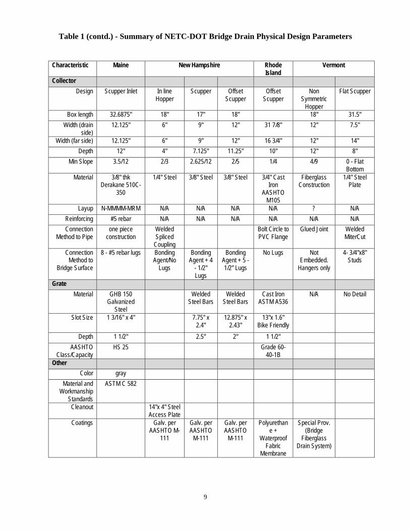
A summary of this survey is given in Table 1. The goal of this task was to use this knowledge as a building block for Task 2 where common standards could be combined to develop an accepted specification for FRP bridge drains across New England.
Table 1 - Summary of NETC-DOT Bridge Drain Physical Design Parameters
Characteristic Maine New Hampshire Rhode Island Vermont
Basic Data Type One Piece
Composite Scupper/Pipe
Welded Steel
Hopper & HSS Drain
Tubes
Offset Steel Scuppers
w/HSS Drain Tubes
Offset Steel Scuppers
w/HSS Drain Tubes
Cast Iron Offset
Scupper
Offset Hopper used to
collect runoff from
expansion joint
Steel Fab. Curb
Downspout
Outer Dimensions
33 7/16" x 13 1/8"
18" x 6" 17"x 9 " 18"x12" 31 7/8" x 16 3/4"
18"x12" 32" x 8"
Inlet Area (sq ft) 3 0.75 1 1.5 3.2 1.5 1.8 Pipe Area (sq ft) 0.29 0.21 0.34 0.56 0.31 0.2 0.39
Drain Pipe Drain Opening Ø8 in 6" x 6" 8" x6" 12" x 8" 8" Nom Dia. 6" Nom Dia 8" x 8"
Pipe Material 3/8" thk Derakane 510C-350
6x6x1/4 HSS
Structural Tube
8x6x1/4 TS Structural
Tube
12x8x3/8 TS Structural
Tube
8" Schedule 80 PVC Pipe
Fiberglass Construction
8x8x1/4 HSS Tube
Layup N-MMMM-MRM
N/A N/A N/A N/A ? N/A
Connection Method
one piece construction
Welded Spliced
Coupling
Bolted Welded Flange
Welded all around
Bolted PVC Pipe Flange
Glued Joint Welded Joints
9
Table 1 (contd.) - Summary of NETC-DOT Bridge Drain Physical Design Parameters
Characteristic Maine New Hampshire Rhode Island
Vermont
Collector Design Scupper Inlet In line
Hopper Scupper Offset
Scupper Offset
Scupper Non
Symmetric Hopper
Flat Scupper
Box length 32.6875" 18" 17" 18" 18" 31.5" Width (drain
side) 12.125" 6" 9" 12" 31 7/8" 12" 7.5"
Width (far side) 12.125" 6" 9" 12" 16 3/4" 12" 14" Depth 12" 4" 7.125" 11.25" 10" 12" 8"
Min Slope 3.5/12 2/3 2.625/12 2/5 1/4 4/9 0 - Flat Bottom
Material 3/8" thk Derakane 510C-
350
1/4" Steel 3/8" Steel 3/8" Steel 3/4" Cast Iron
AASHTO M105
Fiberglass Construction
1/4" Steel Plate
Layup N-MMMM-MRM N/A N/A N/A N/A ? N/A Reinforcing #5 rebar N/A N/A N/A N/A N/A N/A Connection
Method to Pipe one piece
construction Welded Spliced
Coupling
Bolt Circle to PVC Flange
Glued Joint Welded MiterCut
Connection Method to
Bridge Surface
8 - #5 rebar lugs Bonding Agent/No
Lugs
Bonding Agent + 4
- 1/2"Lugs
Bonding Agent + 5 - 1/2" Lugs
No Lugs Not Embedded.
Hangers only
4- 3/4"x8"Studs
Grate Material GHB 150
Galvanized Steel
Welded Steel Bars
Welded Steel Bars
Cast Iron ASTM A536
N/A No Detail
Slot Size 1 3/16" x 4" 7.75" x 2.4"
12.875" x 2.43"
13"x 1.6" Bike Friendly
Depth 1 1/2" 2.5" 2" 1 1/2" AASHTO
Class/Capacity HS 25 Grade 60-
40-1BOther
Color gray Material and
Workmanship Standards
ASTM C 582
Cleanout 14"x 4" Steel Access Plate
Coatings Galv. per AASHTO M-
111
Galv. per AASHTO
M-111
Galv. per AASHTO
M-111
Polyurethane +
Waterproof Fabric
Membrane
Special Prov. (Bridge
Fiberglass Drain System)

10
TASK 2 – DEVELOPMENT OF STANDARD DRAIN REQUIREMENTS FOR NEW AND REHABILITATION PROJECTS
Based on the information collected in Task 1, and in consultation with members of the technical committee assigned to the project, the following activities were completed:
a) Establish specific performance requirements for fiber-reinforced polymer (FRP) compositedrains for highway bridges;
b) Develop guidelines with standard practice for fabrication and installation; andc) Draft standard specifications for FRP drains for bridge projects within the New England
region.The guidelines and specification are applicable for both new bridge construction projects and rehabilitation projects. The standard specification, which were written based on the findings from Task 1, are appended.
CRITERIA FOR BASELINE MECHANICAL PROPERTIES AND DURABILITY REQUIREMENTS
Tensile and compressive mechanical properties for production validation are reported for both the axial and hoop directions of the tubular components, or the transverse and longitudinal directions of inlet bodies (see Section A.5.1 Test Samples), as follows:
1) Tensile strength, tensile modulus of elasticity and ultimate tensile strain are determined inaccordance with ASTM D 3039 Standard Test Method for Tensile Properties of PolymerMatrix Composite Materials, and
2) Compressive strength and ultimate compressive strain are determined in accordance withASTM D 6641 Standard Test Method for Compressive Properties of Polymer MatrixComposite Materials Using a Combined Loading Compression (CLC) Test Fixture.
The mechanical properties are obtained by testing coupons cut from FRP laminates (witness plates) manufactured with the same process, lay-up, fiber reinforcement, resin matrix, fiber content and thickness than the FRP drain scupper bodies, inlets and pipes.
The minimum allowable values for the baseline mechanical properties presented in Table A.5.4.b are established as follows:
1) The ultimate tensile strain of 0.01 in/in (1%) is based on the requirements from theAASHTO Guide Specifications for Design of Bonded FRP Systems for Repair andStrengthening of Concrete Bridge Elements (2012).
2) The allowable tensile strength of 16,000 psi and compressive strength of 22,000 psi areminimum acceptable values for FRP laminates with multidirectional reinforcement andtypical manufacturing processes, fiber content and resin systems used for FRP bridgedrains.
3) The tensile modulus of elasticity of 1,600 ksi is determined based on assuming a linearelastic relationship between tensile stresses and strains until failure.
4) The compressive strain is reported at the required compressive strength of 22,000 psi,instead of at ultimate, because experience with compression testing indicates that beyond
11
this value it is unreliable to measure compressive strains. For simplicity, a minimum compressive strain value of 0.01 in/in (1%) is adopted.
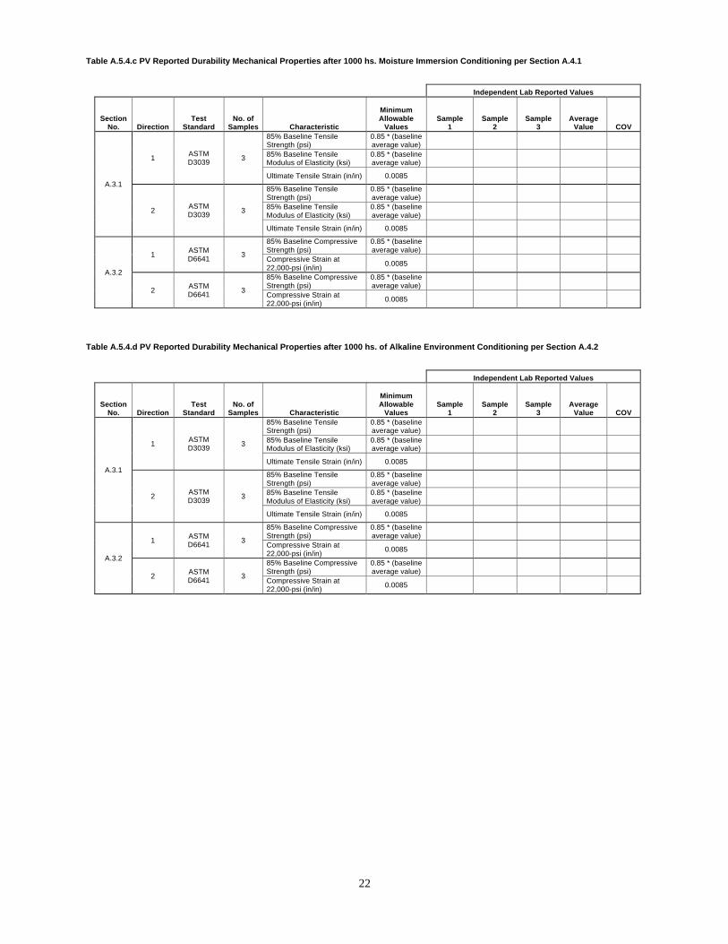
The minimum allowable values for the durability mechanical properties after conditioning in the four different environments, presented in Tables A.5.4.c-f are based on the requirements of the AASHTO Guide Specifications for Design of Bonded FRP Systems for Repair and Strengthening of Concrete Bridge Elements (2012). The requirements are:
1) Retain 85% of the average baseline values of tensile strength, tensile modulus ofelasticity and compressive strength, and
2) Retain 85% of the minimum allowable values of tensile strain and compressive strain.The rationale is that 85% retention of strength and modulus (stiffness) with respect to the baseline values is indicative of the long-term durability of the FRP laminate. Since there is typically greater experimental variability in the measurement of ultimate strains, the corresponding requirement is to retain 85% of the minimum allowable value.
12
FRP COMPOSITE BRIDGE DRAIN COMPONENTS SPECIFICATION
1.0 Description This work consists of items related to the design and manufacture of bridge drains using FRP (Fiber Reinforced Polymer) composite materials. It calls out the minimum material properties and tests, recommended standard geometric scupper design sizes and tolerances, provisions for geometric deviations, tolerances for construction and measurement, practices for installation and attachment, supplier qualifications, acceptance and payment. It does not prescribe specific fiber/matrix materials, lay-ups, grates, attachment hardware, or construction techniques.
1.1 Applicable Standards and References The design and construction of FRP composite bridge drain components shall be in accordance with this Methods Specification and the relevant requirements of the following standards and specifications, unless otherwise stipulated in this specification. Standards and specifications specifically cited in the body of the specification establish requirements that shall have precedence over all others. Should the requirements in any reference conflict with those in another, the reference highest on the list shall govern. It is the Design-Builder's responsibility to obtain clarification of any unresolved ambiguity prior to proceeding with the design or construction.
1.2 Specifications A.) Standard Specifications.
B.) FHWA Hydraulics Engineering Circular No.21 (HEC 21) Design of Bridge Deck Drainage, May 1993.
C.) AASHTO LRFD Guide Specifications for Design of Concrete-Filled FRP Tubes for Flexural and Axial Members, 2012.
D.) AASHTO LRFD Bridge Design Specifications 6th Ed with 2013 Interims, 2012. E.) American Composites Manufacturing Association, ACMA Code of Standard
Practice, First Edition, 2011. F.) ISO/IEC Guide 58, Calibration and Testing Laboratory Accreditation Systems -
General Requirements for Operation and Recognition. G.) ISO/IEC 17025 General Requirements for the Competence of testing and
Calibration Laboratories. H.) NBS Voluntary Product Standard PS15-69. Custom Contact-Mold Reinforced
Polyester Chemical-Resistant Process Equipment. The Society of the Plastics Industry, Inc., 355 Lexington Ave., N.Y., N.Y. 10017
2.3 Standards
A.) ASTM D 2584. Standard Test Method for Ignition Loss of Cured Reinforced Resins. American Society for Testing and Materials, West Conshohocken, PA.
B.) ASTM D 3039. Standard Test Method for Tensile Properties of Polymer Matrix Composite Materials. American Society for Testing and Materials, West Conshohocken, PA.
13
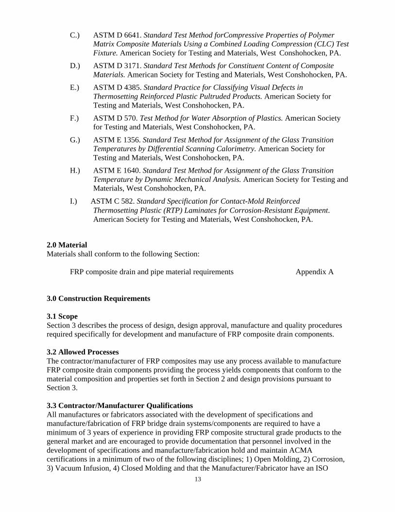
C.) ASTM D 6641. Standard Test Method forCompressive Properties of Polymer Matrix Composite Materials Using a Combined Loading Compression (CLC) Test Fixture. American Society for Testing and Materials, West Conshohocken, PA.
D.) ASTM D 3171. Standard Test Methods for Constituent Content of Composite Materials. American Society for Testing and Materials, West Conshohocken, PA.
E.) ASTM D 4385. Standard Practice for Classifying Visual Defects in Thermosetting Reinforced Plastic Pultruded Products. American Society for Testing and Materials, West Conshohocken, PA.
F.) ASTM D 570. Test Method for Water Absorption of Plastics. American Society for Testing and Materials, West Conshohocken, PA.
G.) ASTM E 1356. Standard Test Method for Assignment of the Glass Transition Temperatures by Differential Scanning Calorimetry. American Society for Testing and Materials, West Conshohocken, PA.
H.) ASTM E 1640. Standard Test Method for Assignment of the Glass Transition Temperature by Dynamic Mechanical Analysis. American Society for Testing and Materials, West Conshohocken, PA.
I.) ASTM C 582. Standard Specification for Contact-Mold Reinforced Thermosetting Plastic (RTP) Laminates for Corrosion-Resistant Equipment. American Society for Testing and Materials, West Conshohocken, PA.
2.0 Material Materials shall conform to the following Section:
FRP composite drain and pipe material requirements Appendix A
3.0 Construction Requirements
3.1 Scope Section 3 describes the process of design, design approval, manufacture and quality procedures required specifically for development and manufacture of FRP composite drain components.
3.2 Allowed Processes The contractor/manufacturer of FRP composites may use any process available to manufacture FRP composite drain components providing the process yields components that conform to the material composition and properties set forth in Section 2 and design provisions pursuant to Section 3.
3.3 Contractor/Manufacturer Qualifications All manufactures or fabricators associated with the development of specifications and manufacture/fabrication of FRP bridge drain systems/components are required to have a minimum of 3 years of experience in providing FRP composite structural grade products to the general market and are encouraged to provide documentation that personnel involved in the development of specifications and manufacture/fabrication hold and maintain ACMA certifications in a minimum of two of the following disciplines; 1) Open Molding, 2) Corrosion, 3) Vacuum Infusion, 4) Closed Molding and that the Manufacturer/Fabricator have an ISO
14
9001:(current year) or other independent certification to ensure that the Manufacturer's process has been independently audited for conformance.
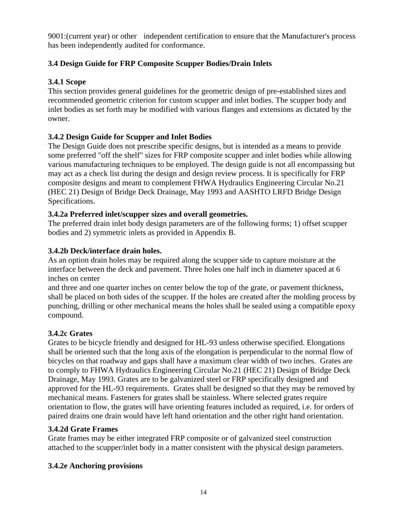
3.4 Design Guide for FRP Composite Scupper Bodies/Drain Inlets
3.4.1 Scope This section provides general guidelines for the geometric design of pre-established sizes and recommended geometric criterion for custom scupper and inlet bodies. The scupper body and inlet bodies as set forth may be modified with various flanges and extensions as dictated by the owner.
3.4.2 Design Guide for Scupper and Inlet Bodies The Design Guide does not prescribe specific designs, but is intended as a means to provide some preferred "off the shelf" sizes for FRP composite scupper and inlet bodies while allowing various manufacturing techniques to be employed. The design guide is not all encompassing but may act as a check list during the design and design review process. It is specifically for FRP composite designs and meant to complement FHWA Hydraulics Engineering Circular No.21 (HEC 21) Design of Bridge Deck Drainage, May 1993 and AASHTO LRFD Bridge Design Specifications. 3.4.2a Preferred inlet/scupper sizes and overall geometries. The preferred drain inlet body design parameters are of the following forms; 1) offset scupper bodies and 2) symmetric inlets as provided in Appendix B.
3.4.2b Deck/interface drain holes. As an option drain holes may be required along the scupper side to capture moisture at the interface between the deck and pavement. Three holes one half inch in diameter spaced at 6 inches on center and three and one quarter inches on center below the top of the grate, or pavement thickness, shall be placed on both sides of the scupper. If the holes are created after the molding process by punching, drilling or other mechanical means the holes shall be sealed using a compatible epoxy compound.
3.4.2c Grates Grates to be bicycle friendly and designed for HL-93 unless otherwise specified. Elongations shall be oriented such that the long axis of the elongation is perpendicular to the normal flow of bicycles on that roadway and gaps shall have a maximum clear width of two inches. Grates are to comply to FHWA Hydraulics Engineering Circular No.21 (HEC 21) Design of Bridge Deck Drainage, May 1993. Grates are to be galvanized steel or FRP specifically designed and approved for the HL-93 requirements. Grates shall be designed so that they may be removed by mechanical means. Fasteners for grates shall be stainless. Where selected grates require orientation to flow, the grates will have orienting features included as required, i.e. for orders of paired drains one drain would have left hand orientation and the other right hand orientation.
3.4.2d Grate Frames Grate frames may be either integrated FRP composite or of galvanized steel construction attached to the scupper/inlet body in a matter consistent with the physical design parameters.
3.4.2e Anchoring provisions

15
Scupper/inlet anchoring shall be bonded to the grate framing in a manner that provides a load path into the concrete decking. Anchor details to be specified in the project plans and design reviews. Drain pipe anchoring shall follow standard practice for areas not subject to flooding. Anchoring of drain pipes located over streams where flooding may occur shall be designed to meet loads related to floating debris and/or ice flows. 3.4.2f Cross and Longitudinal Slope Compensation The scupper/inlet designs shall provide a means to match the grate to the deck angles while maintaining the downspout in a plumb orientation. If purchased in pairs one left handed version will be required for each right handed version. This may be achieved when a down spout portion is bonded to the scupper body, through the frame attachment to the scupper body or through any other viable option.
3.4.3 Provisions for Custom Design Scupper and Inlet Bodies The Design Guide does offer provisions for custom designs. Any design acceptable to the owner that complies to FHWA Hydraulics Engineering Circular No.21 (HEC 21) Design of Bridge Deck Drainage, May 1993 is acceptable provided the material composition and properties set forth in Section 2 of this standard are complied to and the wall thicknesses are greater than or equal to 1/4 inch.
3.4.4 FRP Composite Drain Sections Bridge deck downspouts, bridge drain deck extensions, elbows and pipe for under drains are recommended to be constructed using circular cross sections, however other cross sections are allowed upon engineering approval. Drain sections shall comply to the material requirements set forth in Section 2 and maintain wall thickness of no less than 1/8 inch for dry crossings and no less than 1/4 inch over stream crossings where ice flows or floating debris may pose a problem during flood events.
3.4.5 FRP Composite Deck Drain Extensions. Down spout drain extensions may be integrated and bonded directly to the scupper bodies without additional lateral supports for lengths up to 4 feet. Downspouts extensions between 4 feet and 8 feet require additional support and shall be attached to the bridge deck or components that move in direct relation to the scupper/inlet body.
Where additional supports cannot be anchored to locations that move directly with the scupper/inlet body or an extension greater than 8 feet is required, a hopper style inlet necked down to the down spout diameter shall be used. Hoppers shall be designed to encircle the downspout with a one inch concentric clearance and down spout inserted to a minimum of 2 inches into the catch hopper. Fastening schedules of the drain piping to be designed according to the manufacturers recommendations.
3.4.6 Transitions through Connections and Components. All transitions and joints to be manufactured through the use of smooth radius molds. Miter joint and edged transitions are not allowed. All internal joint connections are to be smooth and continuous.
3.4.7 Pigmented FRP Composite Drain Components Pipes, fittings, bodies and all FRP composite drain system components shall be pigmented through the wall. Color to be standard concrete-grey or other neutral color as agreed within the contract documents. Paint, gel-coat or any other exterior coating shall not be accepted.

16
3.4.8 Joint Connections Joints may be welded using manufacturer recommended adhesives in accordance to the adhesive manufacturer's application procedures. Adhesives must be compatible with the FRP resins, applied in a way that ensures complete bonding and liquid tight sealing of the resins, and be compatible with the environmental conditions such as temperature, freeze thaw conditions, and wet alkaline environments.
3.4.9 Design Review The contractor/manufacturer of FRP composite drain components shall submit approval drawings to the Resident Engineer providing design and manufacturing details relevant to the application and standard specifications. The Resident Engineer shall be allowed 7 working days to review the submittal.
3.4.9a Submitted Drawings Drawings shall include dimensions and tolerances necessary for manufacture and installation, all hardware, orienting features, anchor details, fastener details, gasket details, cross and longitudinal matching features, joint details, transition details, material lay-up/composition as to be certified under Section 2, other items as listed in Section 3 and any other information as requested by the Resident Engineer.
3.4.9b Manufacturing Control Plan The manufacturer shall submit a manufacturing and inspection control plan to the Resident Engineer for review. Inspection dimensions should correspond to dimensions on the drawings.
3.4.9c Authorization to Manufacture After design review and sign off of the drawings and control plans the constructor shall proceed with manufacturing and supply of components per the agreed manufacturing plan and design.
3.4.10 Inspection of Components The manufacturer of components shall supply all agreed inspection data and manufacturing composition data per Table 2.5.4a to the Resident Engineer prior to and with the shipping of components. All agreed inspection dimensions and items per control plans shall be in conformance of the plans. In the case of non-conformities the contractor will not be allowed to ship unless a signed deviation waiver is granted by the resident engineer.
3.4.11 Packaging, Storage and Shipping of Components FRP drains shall be stored and handled in accordance with the manufacturer's recommendation. Shipping shall meet the schedule as set forth by the purchasing agreement and/or needs for installation.
3.4.12 Receipt and Inspection of Components FRP drains are to be received and stored at the contractors installation sight per the purchasing agreement in accordance to the manufacturer's recommendation. Inspection of the components may be conducted to verify the inspection dimensions provided by the manufacturer.
3.4.13 Installation The contractor will shall install the FRP drains in accordance to the manufacturer's installation procedures and in accordance to the contractor's installation drawings. Any repairs to the drains
17
as a result of mishandling at the installation sight shall be done at the expense of the contractor in accordance to the manufacturer's recommendations.
4.0 Measurement and Payment
4.1 Method of Measurement FRP Bridge Drains will be measured by the number of units, for fabrication and delivery. Installation for the drains will be incidental to the Structural Concrete Superstructure item.
4.2 Basis of Payment FRP Bridge Drains will be paid for at the contract unit price. Such payment will include compensation for the fabrication and delivery of the drains in accordance with this specification.
Payment will be under:
Pay Item Pay Unit XXX.XX FRP Bridge Drain Description Each

18
APPENDIX A: FRP COMPOSITE DRAIN AND PIPE MATERIAL REQUIREMENTS.
A.1 ScopeThis section specifies the material composition, properties, test requirements and reports thatshall be submitted and approved prior to and after product certification of each FRP compositedrain component type, e.g. scupper body or pipe component. The manufacturer is responsible fortesting using an approved independent lab per section A.5.3. Once certified the approved productmay be manufactured with only internal testing provided the manufacturing process and laminatecomposition do not change. Changes to process and or composition do require additional testingand product certification. The manufacturer shall report the individual test results per sectionA.5.3. If the strength is less than the required properties certification will not be granted.
A.2 Material/Laminate CompositionA.2.1 FibersFiber sizings and coupling agents shall be compatible with the resin system used to impregnatethem.
A.2.2 Matrix ResinsCommercial grades of vinyl ester and epoxy resin systems are permitted provided the finishedproduct meets the material property requirements before and after durability conditioning as setforth in Section A. Styrene is permitted to be added to the polymer resin during processing.Added styrene shall be less than 10 percent by mass of the polymer resin. The amount of styrene,as a mass percentage of the polymer resin, added during processing shall be reported per SectionA.5.3.
A.2.3 Fillers and AdditivesCommercial grade inorganic fillers such as kaolin clay, calcium carbonate, and alumina tri-hydrate shall not exceed 20 percent by mass of the polymer resin constituent. Commercial gradeadditives and process-aids, such as release agents, low profile shrink additives, initiators,promoters, hardeners, catalysts, pigments, fire-retardants, and ultra-violet inhibitors are permittedand depend on the processing method. Shrink additives, if used, shall be less than 20 percent bymass of the polymer resin. Commercial grade inorganic or organic non-woven surfacing mats orveils are permitted.
A.2.4 Fiber ContentFiber content shall be measured by ASTM D 3171 or ASTM D 2584. Fiber content shall be highenough to meet the mechanical property requirements of the FRP system laminate. Themanufacturer shall report the fiber content of the end product by volume or by mass inaccordance to the method used. If fiber content is not provided by the manufacturer, then themanufacturer shall provide material data sheets with the weight per unit area of the fiberreinforcement used to manufacture the part.
A.2.5 Glass Transition TemperatureThe characteristic value of the glass transition temperature of the composite system, determinedin accordance with ASTM E1640, shall be at least 40 degrees Fahrenheit higher than themaximum design temperature, TMaxDesign, defined in section 3.12.2.2 of the AASHTO LRFDGuide Specifications for Design of Concrete-Filled FRP Tubes for Flexural and Axial Members,

19
2012. FRP drain systems may not be used in environments with a service temperature higher than the glass transition temperature of the resin used for their manufacturing.
A.2.6 Longitudinal and Transverse Coefficients of Thermal Expansion (CTE)The coefficient of Thermal Expansion (CTE) of the tube may vary in the longitudinal andcircumferential directions of the component depending on the laminate architecture and type offibers and resins.
A.3 Mechanical Properties
A.3.1 Tensile PropertiesThe tensile strength, tensile modulus of elasticity, and ultimate tensile strain shall be determinedfor both the axial and hoop directions of the tubular components or in transverse and longitudinaldirections of inlet bodies, see Section A.5.1 Test Samples. The tensile strength as reported by themanufacturer for product certification shall be measured according to ASTM Test Method D3039, or other tension test method designed to determine tensile properties of compositelaminates at the approved frequency and number of specimens as specified in section A.5.
A.3.2 Compressive PropertiesThe compressive strength and ultimate compressive strain shall be determined for thelongitudinal directions of the tube laminate. The compressive strength and ultimate compressivestrains shall be derived from specimens tested in accordance with ASTM Test Method D 6641,or other approved compression test method designed to determine compressive properties of thecomposite.
A.4 Durability PropertiesMaterial properties shall retain 85% of their baseline values for the material properties listed inSection 2.3 after conditioning for all the durability tests listed below. Durability test methods areadopted from AASHTO Guide Specifications for Design of Bonded FRP Systems for Repair andStrengthening of Concrete Bridge Elements, 2012.
Durability property testing is only required for initial product certification and not required for subsequent production orders. The testing is the responsibility of the manufacturer and shall be conducted by an approved independent testing lab per section A.5.2.
A.4.1 Moisture AbsorptionSamples will be immersed in distilled water having a temperature of 100 +/-3 degrees Fahrenheitand tested after 1,000 hours of exposure.
A.4.2 Resistance to Alkaline EnvironmentSamples will be immersed in a saturated solution of calcium hydroxide (pH-11) at ambienttemperature of 73 +/-3 degrees Fahrenheit for 1,000 hours prior to testing. The pH level will bemonitored and the solution will be maintained as needed.
A.4.3 Alternating Ultraviolet Light and Condensation HumiditySamples will be conditioned in an apparatus under Cycle I-UV exposure condition according toASTM G154 Standard Practice. Samples will be tested within two hours after removal from theapparatus.

20
A.4.4 Freeze-ThawSamples will be exposed to 100 repeated cycles of freezing and thawing in an apparatus meetingthe requirements of ASTM C666.
A.5 Sampling, Testing & Results.
A.5.1 Test Samples.The manufacturer is responsible for testing and may use samples in accordance to the testmethods and needs of test equipment available. Test coupons may be cut from manufacturedproducts or prepared using identical processes, e.g., wet lay-up, vacuum infusion, etc. in a flatsheet, or witness plate, in which test coupons may be cut. Approval of the engineer shall berequired for acceptance of test specimens produced by a different manufacturing method.Samples derived from special coupon test sheets shall be taken interior to edge sections 1.5x thewidth of the required coupon width. Samples shall be prepared from samples oriented with thedirections illustrated in figures 1 and 2 for scupper body and drain pipes. For samples fromfilament wound pipes, samples shall be constructed over polygon mandrels allowing for flatpanels to be removed for test purposes. Each test shall use a quantity of three samples. SeeTables A.5.4 for tests, material requirements and sample breakdown.
A.5.2 Test Lab Requirements.All testing of FRP material properties is be conducting in accordance to specified standards.Internal or external testing is to be conducted through laboratory facilities in accordance toISO/IEC Guide 58, Calibration and Testing Laboratory Accreditation Systems - GeneralRequirements for Operation and Recognition and ISO/IEC 17025 General Requirements for theCompetence of testing and Calibration Laboratories as related by AASHTO document R18"Recommended Practice for Establishing and Implementing a Quality System for ConstructionMaterials Testing Laboratories."
A.5.3 Production Validation (PV) Testing.Certification of materials used in FRP drain products must undergo PV testing of the specifiedmaterial properties before and after environmental conditioning as set forth in Section A.5.4 by

21
an independent lab. PV tests may be conducted internally by the manufacturer for development but are not acceptable for certification. Reported values for the material composition is be recorded and reported by the manufacturer, no independent audit is required.
A.5.4 Production Validation Sample Quantities, Minimum Material Properties andReported Values
The following data shall be reported for material certification. Note that the tables shown use orientations related to FRP scupper or inlet bodies as set forth in Figure 1 of Section A.5.1, orientation direction 2 as shown in Figure 2 of Section A.5.1 shall be substituted for orientation direction 3 when evaluating tubular sections. The required number of samples has been reduced from ASTM requirements.
Table A.5.4.a PV Reported Material Composition Data (Recorded by the manufacturer during the manufacturing process)
Table A.5.4.b PV Reported Baseline Mechanical Properties Table A.5.4.b PV Reported Baseline Mechanical Properties
Independent Lab Reported Values
Section No. Direction
Test Standard
No. of Samples Characteristic
Minimum Allowable
Values Sample
1 Sample
2 Sample
3 Average
Value COV
A.3.1
1 ASTM D3039 3
Tensile Strength (psi) 16,000
Tensile Modulus of Elasticity (ksi) 1,600
Ultimate Tensile Strain (in/in) 0.01
2 ASTM D3039 3
Tensile Strength (psi) 16,000
Tensile Modulus of Elasticity (ksi) 1,600
Ultimate Tensile Strain (in/in) 0.01
A.3.2
1 ASTM D6641 3
Compressive Strength (psi) 22,000
Compressive Strain at 22,000-psi (in/in) 0.01
2 ASTM D6641 3
Compressive Strength (psi) 22,000
Compressive Strain at 22,000-psi (in/in) 0.01
22
Table A.5.4.c PV Reported Durability Mechanical Properties after 1000 hs. Moisture Immersion Conditioning per Section A.4.1
Table A.5.4.d PV Reported Durability Mechanical Properties after 1000 hs. of Alkaline Environment Conditioning per Section A.4.2
Table A.5.4.c PV Reported Baseline Mechanical Properties after 1000 hs. Moisture Immersion Conditioning per Section A.4.1
Independent Lab Reported Values
Section No. Direction
Test Standard
No. of Samples Characteristic
Minimum Allowable
Values Sample
1 Sample
2 Sample
3 Average
Value COV
A.3.1
1 ASTM D3039 3
85% Baseline Tensile Strength (psi)
0.85 * (baseline average value)
85% Baseline Tensile Modulus of Elasticity (ksi)
0.85 * (baseline average value)
Ultimate Tensile Strain (in/in) 0.0085
2 ASTM D3039 3
85% Baseline Tensile Strength (psi)
0.85 * (baseline average value)
85% Baseline Tensile Modulus of Elasticity (ksi)
0.85 * (baseline average value)
Ultimate Tensile Strain (in/in) 0.0085
A.3.2
1 ASTM D6641 3
85% Baseline Compressive Strength (psi)
0.85 * (baseline average value)
Compressive Strain at 22,000-psi (in/in) 0.0085
2 ASTM D6641 3
85% Baseline Compressive Strength (psi)
0.85 * (baseline average value)
Compressive Strain at 22,000-psi (in/in) 0.0085

23
Table A.5.4.e PV Reported Durability Mechanical Properties after UV Light Conditioning per Section A.4.3 (ASTM G154)
Table A.5.4.f PV Reported Durability Mechanical Properties after 100 Freeze-Thaw Cycles Conditioning per Section A.4.4 (ASTM C666)
Table A.5.4.c PV Reported Baseline Mechanical Properties after 1000 hs. Moisture Immersion Conditioning per Section A.4.1
Independent Lab Reported Values
Section No. Direction
Test Standard
No. of Samples Characteristic
Minimum Allowable
Values Sample
1 Sample
2 Sample
3 Average
Value COV
A.3.1
1 ASTM D3039 3
85% Baseline Tensile Strength (psi)
0.85 * (baseline average value)
85% Baseline Tensile Modulus of Elasticity (ksi)
0.85 * (baseline average value)
Ultimate Tensile Strain (in/in) 0.0085
2 ASTM D3039 3
85% Baseline Tensile Strength (psi)
0.85 * (baseline average value)
85% Baseline Tensile Modulus of Elasticity (ksi)
0.85 * (baseline average value)
Ultimate Tensile Strain (in/in) 0.0085
A.3.2
1 ASTM D6641 3
85% Baseline Compressive Strength (psi)
0.85 * (baseline average value)
Compressive Strain at 22,000-psi (in/in) 0.0085
2 ASTM D6641 3
85% Baseline Compressive Strength (psi)
0.85 * (baseline average value)
Compressive Strain at 22,000-psi (in/in) 0.0085
24
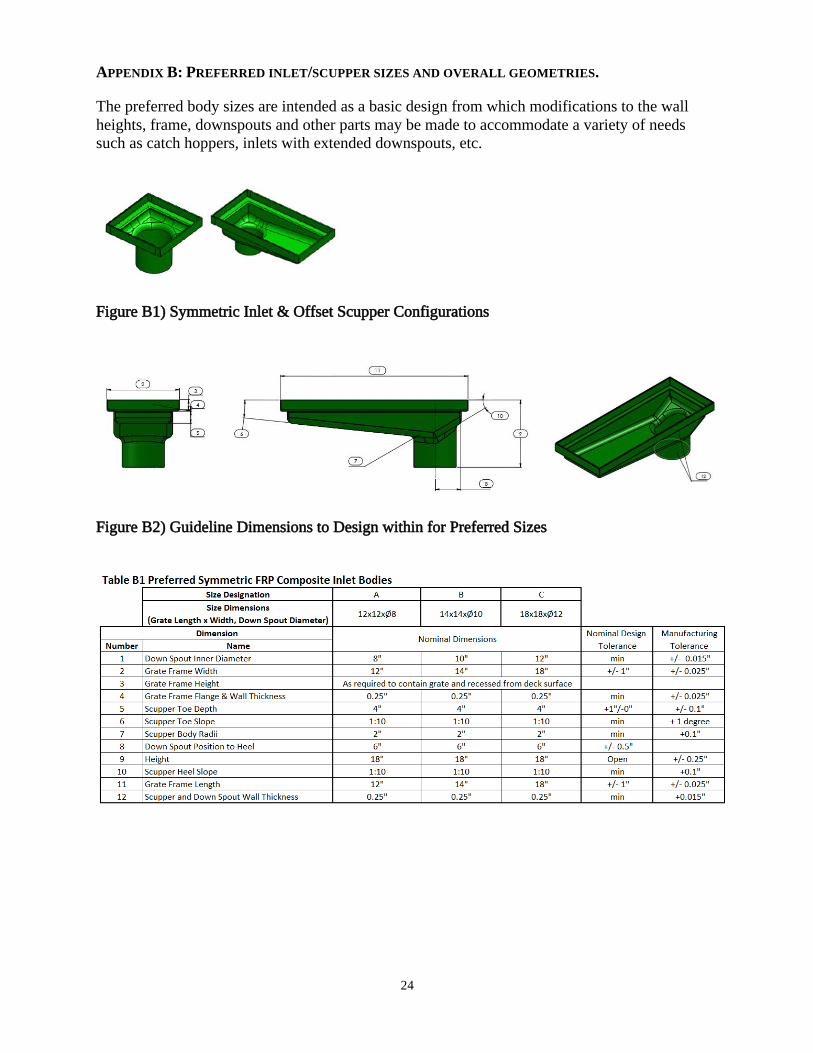
APPENDIX B: PREFERRED INLET/SCUPPER SIZES AND OVERALL GEOMETRIES.
The preferred body sizes are intended as a basic design from which modifications to the wall heights, frame, downspouts and other parts may be made to accommodate a variety of needs such as catch hoppers, inlets with extended downspouts, etc.
Figure B1) Symmetric Inlet & Offset Scupper Configurations
Figure B2) Guideline Dimensions to Design within for Preferred Sizes

25

26
APPENDIX C: SPECIAL PROVISION FOR FRP BRIDGE DRAINS FOR THE HOWLAND-ENFIELDBRIDGE, MAINE
MaineDOT implemented the FRP bridge drain specifications developed in this NETC 09-03 project for the Howland-Enfield Bridge (WIN 016705.00) as a Special Provision, Section 502, Structural Concrete. Maine DOT replaced an existing bridge over the Penobscot River between the towns of Howland and Enfield with a four span 940 foot composite steel and concrete bridge. The contractor is Reed & Reed and the contract completion date is December 30, 2017. The shop drawings prepared by Kenway Corp. for of Type B and Type G FRP drains are appended. The laminate lay-up is shown in the drawings.

27

28

29

30

31
TASK 3 - SELECTION OF PARTICIPATING FRP DRAIN SUPPLIERS
A comprehensive search of FRP bridge drain suppliers was conducted by contacting transportation agencies and the American Composites Manufacturing Association. The criteria for selecting the FRP suppliers considered:
a) Manufacturing capabilities for supplying both the scupper and the drainage piping;b) Experience supplying and installing FRP drains in bridge projects with transportation
agencies in the Northeast; andc) Interest in participating in the qualification program by supplying material samples.
Two FRP drain suppliers were selected with the approval of the NETC Technical Committee: a) Kenway Corporation, and b) FRP Bridge Drain Pipe-Westfall Company. The suppliers contributed in-kind to the project by:
a) Providing information regarding prior bridge drain experience;b) Providing technical expertise regarding the dimensions and requirements for FRP bridge
drains;c) Reviewing the draft specifications; andd) Providing composite material samples for testing and qualification.
32
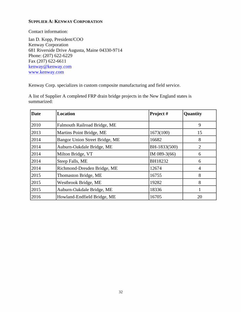
SUPPLIER A: KENWAY CORPORATION
Contact information:
Ian D. Kopp, President/COO Kenway Corporation 681 Riverside Drive Augusta, Maine 04330-9714 Phone: (207) 622-6229 Fax (207) 622-6611 [email protected] www.kenway.com
Kenway Corp. specializes in custom composite manufacturing and field service.
A list of Supplier A completed FRP drain bridge projects in the New England states is summarized:
Date Location Project # Quantity
2010 Falmouth Railroad Bridge, ME 9 2013 Martins Point Bridge, ME 1673(100) 15 2014 Bangor Union Street Bridge, ME 16682 8 2014 Auburn-Oakdale Bridge, ME BH-1833(500) 2 2014 Milton Bridge, VT IM 089-3(66) 6 2014 Steep Falls, ME BH18232 6 2014 Richmond-Dresden Bridge, ME 12674 4 2015 Thomaston Bridge, ME 16755 8 2015 Westbrook Bridge, ME 19282 8 2015 Auburn-Oakdale Bridge, ME 18336 1 2016 Howland-Endfield Bridge, ME 16705 20
33
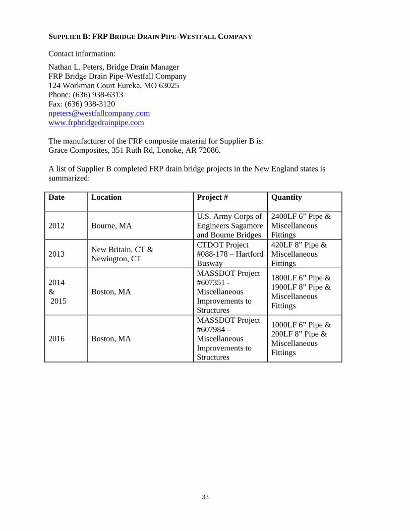
SUPPLIER B: FRP BRIDGE DRAIN PIPE-WESTFALL COMPANY
Contact information:
Nathan L. Peters, Bridge Drain Manager FRP Bridge Drain Pipe-Westfall Company 124 Workman Court Eureka, MO 63025 Phone: (636) 938-6313 Fax: (636) 938-3120 [email protected] www.frpbridgedrainpipe.com
The manufacturer of the FRP composite material for Supplier B is: Grace Composites, 351 Ruth Rd, Lonoke, AR 72086.
A list of Supplier B completed FRP drain bridge projects in the New England states is summarized:
Date Location Project # Quantity
2012 Bourne, MA U.S. Army Corps of Engineers Sagamore and Bourne Bridges
2400LF 6” Pipe & Miscellaneous Fittings
2013 New Britain, CT & Newington, CT
CTDOT Project #088-178 – Hartford Busway
420LF 8” Pipe & Miscellaneous Fittings
2014 & 2015
Boston, MA
MASSDOT Project #607351 - Miscellaneous Improvements to Structures
1800LF 6” Pipe & 1900LF 8” Pipe & Miscellaneous Fittings
2016 Boston, MA
MASSDOT Project #607984 – Miscellaneous Improvements to Structures
1000LF 6” Pipe & 200LF 8” Pipe & Miscellaneous Fittings

34
TASK 4: QUALIFICATION OF FRP DRAIN SUPPLIERS THROUGH MATERIAL TESTING
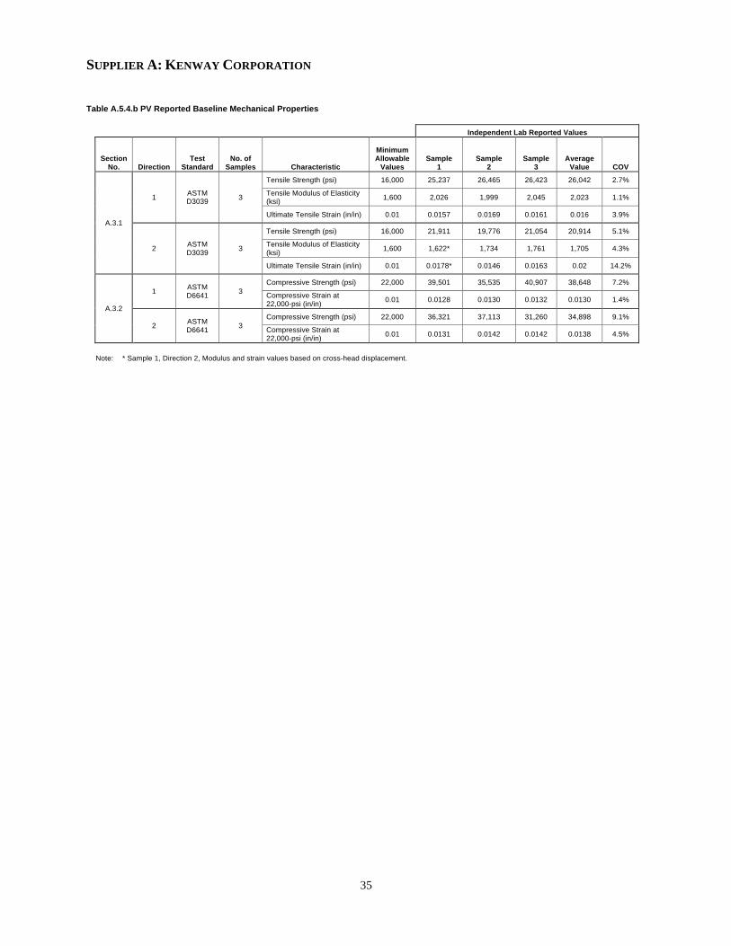
Suppliers A and B provided composite material samples for testing and qualification for use in FRP Bridge drains according to Appendix A of the specification presented in Task 2. This one time series of tests was conducted to ensure materials used would be durable and meet the requirements of bridge projects. The goal of these tests was to prequalify FRP drain suppliers and expedite the process of demonstrating these advanced composite materials for bridge installations. This section presents the test reports of coupons cut from FRP laminated plates manufactured with the same process and laminate composition of the composite drain components (scupper body or pipe). The tests were conducted by the University of Maine’s Advanced Structures and Composites Center, which is an ISO 17025 accredited testing laboratory. The reported values for suppliers A and B exceeded the minimum allowable values for the baseline mechanical properties (Table A.5.4.b). Supplier A exceeded the minimum allowable values for the durability mechanical properties for the four environmental conditions specified (Table A.5.4.c-f). Supplier B exceeded the minimum allowable values for the durability mechanical properties for the four environmental conditions specified (Table A.5.4.c-f) with two exceptions. The average value of tensile strength for Supplier B after 1000 hours of water immersion at 100°F was 25,807 psi, which is 74% of the corresponding baseline value. However, this retained value exceeds the baseline minimum allowable value of 16,000 psi. Since all other retained values for this environmental condition exceeded the minimum allowable values, the production validation is considered satisfactory. The second exception for Supplier B is the retained average compressive strain at 22,000 psi of 0.0083 after UV light conditioning, which is slightly lower than the minimum allowable value of 0.0085. This small difference is within the typical experimental variability for strain measurements.
The average thickness of the Supplier A material was 0.237 in, and for the Supplier B material was 0.308 in. The production validation tables for baseline and durability mechanical properties for suppliers A and B are presented.
35
SUPPLIER A: KENWAY CORPORATION
Table A.5.4.b PV Reported Baseline Mechanical Properties
Table A.5.4.b PV Reported Baseline Mechanical Properties
Supplier A: Kenway Corporation
Independent Lab Reported Values
Section No. Direction
Test Standard
No. of Samples Characteristic
Minimum Allowable
Values Sample
1 Sample
2 Sample
3 Average
Value COV
A.3.1
1 ASTM D3039 3
Tensile Strength (psi) 16,000 25,237 26,465 26,423 26,042 2.7%
Tensile Modulus of Elasticity (ksi) 1,600 2,026 1,999 2,045 2,023 1.1%
Ultimate Tensile Strain (in/in) 0.01 0.0157 0.0169 0.0161 0.016 3.9%
2 ASTM D3039 3
Tensile Strength (psi) 16,000 21,911 19,776 21,054 20,914 5.1%
Tensile Modulus of Elasticity (ksi) 1,600 1,622* 1,734 1,761 1,705 4.3%
Ultimate Tensile Strain (in/in) 0.01 0.0178* 0.0146 0.0163 0.02 14.2%
A.3.2
1 ASTM D6641 3
Compressive Strength (psi) 22,000 39,501 35,535 40,907 38,648 7.2%
Compressive Strain at 22,000-psi (in/in) 0.01 0.0128 0.0130 0.0132 0.0130 1.4%
2 ASTM D6641 3
Compressive Strength (psi) 22,000 36,321 37,113 31,260 34,898 9.1%
Compressive Strain at 22,000-psi (in/in) 0.01 0.0131 0.0142 0.0142 0.0138 4.5%
Note: * Sample 1, Direction 2, Modulus and strain values based on cross-head displacement.

36
Table A.5.4.c PV Reported Durability Mechanical Properties after 1000 hs. Moisture Immersion Conditioning per Section A.4.1
Table A.5.4.d PV Reported Durability Mechanical Properties after 1000 hs. of Alkaline Environment Conditioning per Section A.4.2
Table A.5.4.c PV Reported Baseline Mechanical Properties after 1000 hs. Moisture Immersion Conditioning per Section A.4.1
Supplier A: Kenway Corporation
Independent Lab Reported Values
Section No. Direction
Test Standard
No. of Samples Characteristic
Minimum Allowable
Values Sample
1 Sample
2 Sample
3 Average
Value COV
A.3.1
1 ASTM D3039 3
Tensile Strength (psi) 22,136 22,257 22,801 22,469 22,509 1.2%
Tensile Modulus of Elasticity (ksi) 1,720 1,871 1,732 1,788 1,797 3.9%
Ultimate Tensile Strain (in/in) 0.0085 0.0146 0.0146 0.0154 0.0149 3.1%
2 ASTM D3039 3
Tensile Strength (ksi) 17,777 21,163 20,211 19,401 20,258 4.4%
Tensile Modulus of Elasticity (psi) 1,450 1,839 1,730 1,742 1,770 3.4%
Ultimate Tensile Strain (in/in) 0.0085 0.0149 0.0153 0.0138 0.0147 5.3%
A.3.2
1 ASTM D6641 3
Compressive Strength (psi) 32,851 36,152 36,952 39,504 37,536 4.7%
Compressive Strain at 22,000-psi (in/in) 0.0085 0.0131 0.0122 0.0117 0.0124 5.8%
2 ASTM D6641 3
Compressive Strength (psi) 29,663 32,992 35,260 33,557 33,937 3.5%
Compressive Strain at 22,000-psi (in/in) 0.0085 0.0129 0.0137 0.0139 0.0135 3.9%
Table A.5.4.d PV Reported Baseline Mechanical Properties after 1000 hs. of Alkaline Environment Conditioning per Section A.4.2
Supplier A: Kenway Corporation
Independent Lab Reported Values
Section No. Direction
Test Standard
No. of Samples Characteristic
Minimum Allowable
Values Sample
1 Sample
2 Sample
3 Average
Value COV
A.3.1
1 ASTM D3039 3
Tensile Strength (psi) 22,136 28,225 28,224 26,675 27,708 3.2%
Tensile Modulus of Elasticity (ksi) 1,720 1,967 1,955 2,099 2,007 4.0%
Ultimate Tensile Strain (in/in) 0.0085 0.0185 0.0183 0.0157 0.0175 9.0%
2 ASTM D3039 3
Tensile Strength (psi) 17,777 21,197 21,967 21,521 21,562 1.8%
Tensile Modulus of Elasticity (ksi) 1,450 1,899 1,920 1,891 1,903 0.8%
Ultimate Tensile Strain (in/in) 0.0085 0.0142 0.0150 0.0155 0.015 4.4%
A.3.2
1 ASTM D6641 3
Compressive Strength (psi) 32,851 38,758 35,764 38,442 37,655 4.4%
Compressive Strain at 22,000-psi (in/in) 0.0085 0.0113 0.0103 0.0102 0.0106 5.5%
2 ASTM D6641 3
Compressive Strength (psi) 29,663 37,624 37,546 36,456 37,209 1.8%
Compressive Strain at 22,000-psi (in/in) 0.0085 0.0126 0.0131 0.0131 0.0129 2.3%

37
Table A.5.4.e PV Reported Durability Mechanical Properties after UV Light Conditioning per Section A.4.3 (ASTM G154)
Table A.5.4.f PV Reported Durability Mechanical Properties after 100 Freeze-Thaw Cycles Conditioning per Section A.4.4 (ASTM C666)
Table A.5.4.e PV Reported Baseline Mechanical Properties after UV Light Conditioning per Section A.4.3 (ASTM G154)
Supplier A: Kenway Corporation
Independent Lab Reported Values
Section No. Direction
Test Standard
No. of Samples Characteristic
Minimum Allowable
Values Sample
1 Sample
2 Sample
3 Average
Value COV
A.3.1
1 ASTM D3039 3
Tensile Strength (psi) 22,136 25,429 24,542 23,767 24,579 3.4%
Tensile Modulus of Elasticity (ksi) 1,720 2,132 1,972 1,937 2,014 5.2%
Ultimate Tensile Strain (in/in) 0.0085 0.01480 0.01507 0.01433 0.01473 2.6%
2 ASTM D3039 3
Tensile Strength (psi) 17,777 21,239 21,138 21,206 21,194 0.2%
Tensile Modulus of Elasticity (ksi) 1,450 1,685 1,783 1,764 1,744 3.0%
Ultimate Tensile Strain (in/in) 0.0085 0.0184 0.0163 0.0170 0.0172 6.2%
A.3.2
1 ASTM D6641 3
Compressive Strength (psi) 32,851 33,419 33,711 41,414 36,181 12.5%
Compressive Strain at 22,000-psi (in/in) 0.0085 0.0130 0.0124 0.0136 0.0130 4.6%
2 ASTM D6641 3
Compressive Strength (psi) 29,663 38,102 40,092 41,360 39,851 4.1%
Compressive Strain at 22,000-psi (in/in) 0.0085 0.0119 0.0127 0.0119 0.0121 3.7%
Table A.5.4.f PV Reported Baseline Mechanical Properties after 100 Freeze-Thaw Cycle Conditioning per Section A.4.4 (ASTM C666)
Supplier A: Kenway Corporation
Independent Lab Reported Values
Section No. Direction
Test Standard
No. of Samples Characteristic
Minimum Allowable
Values Sample
1 Sample
2 Sample
3 Average
Value COV
A.3.1
1 ASTM D3039 3
Tensile Strength (psi) 22,136 26,841 24,835 26,059 25,912 3.9%
Tensile Modulus of Elasticity (ksi) 1,720 1,853 1,873 1,924 1,883 2.0%
Ultimate Tensile Strain (in/in) 0.0085 0.0180 0.0164 0.0165 0.017 5.3%
2 ASTM D3039 3
Tensile Strength (psi) 17,777 20,028 19,322 20,610 19,987 3.2%
Tensile Modulus of Elasticity (ksi) 1,450 1,754 1,713 1,706 1,724 1.5%
Ultimate Tensile Strain (in/in) 0.0085 0.0143 0.0143 0.0160 0.015 6.7%
A.3.2
1 ASTM D6641 3
Compressive Strength (psi) 32,851 39,505 36,319 42,360 39,395 7.7%
Compressive Strain at 22,000-psi (in/in) 0.0085 0.0108 0.0126 0.0116 0.0117 7.7%
2 ASTM D6641 3
Compressive Strength (psi) 29,663 33,736 34,932 36,964 35,211 4.6%
Compressive Strain at 22,000-psi (in/in) 0.0085 0.0137 0.0142 0.0144 0.0141 2.3%

38
SUPPLIER B: FRP BRIDGE DRAIN PIPE-WESTFALL COMPANY
Table A.5.4.b PV Reported Baseline Mechanical Properties Table A.5.4.b PV Reported Baseline Mechanical Properties
Supplier B: FRP Bridge Drain Pipe – Westfall Company – Grace Composites Independent Lab Reported Values
Section No. Direction
Test Standard
No. of Samples Characteristic
Minimum Allowable
Values Sample
1 Sample
2 Sample
3 Average
Value COV
A.3.1
1 ASTM D3039 3
Tensile Strength (psi) 16,000 34,222 35,134 34,610 34,656 1.3%
Tensile Modulus of Elasticity (ksi) 1,600 2,165 2,284 2,203 2,217 2.7%
Ultimate Tensile Strain (in/in) 0.01 0.0209 0.0204 0.0251 0.0221 11.6%
2 ASTM D3039 3
Tensile Strength (psi) 16,000 32,975 32,127 32,684 32,595 1.3%
Tensile Modulus of Elasticity (ksi) 1,600 2,084 2,060 2,029 2,058 1.3%
Ultimate Tensile Strain (in/in) 0.01 0.0220 0.0212 0.0223 0.0218 2.7%
A.3.2
1 ASTM D6641 3
Compressive Strength (psi) 22,000 36,339 34,180 35,368 35,296 3.1%
Compressive Strain at 22,000-psi (in/in) 0.01 0.0092 0.0086 0.0107 0.0095 11.4%
2 ASTM D6641 3
Compressive Strength (psi) 22,000 32,508 32,973 31,801 32,427 1.8%
Compressive Strain at 22,000-psi (in/in) 0.01 0.0106 0.0106 0.0098 0.0103 4.3%

39
Table A.5.4.c PV Reported Durability Mechanical Properties after 1000 hs. Moisture Immersion Conditioning per Section A.4.1
Table A.5.4.d PV Reported Durability Mechanical Properties after 1000 hs. of Alkaline Environment Conditioning per Section A.4.2
Table A.5.4.c PV Reported Baseline Mechanical Properties after 1000 hs. Moisture Immersion Conditioning per Section A.4.1
Supplier B: FRP Bridge Drain Pipe – Westfall Company – Grace Composites Independent Lab Reported Values
Section No. Direction
Test Standard
No. of Samples Characteristic
Minimum Allowable
Values Sample
1 Sample
2 Sample
3 Average
Value COV
A.3.1
1 ASTM D3039 3
85% Baseline Tensile Strength (psi) 29,458 25,771 25,087 26,564 25,807** 2.9%
85% Baseline Tensile Modulus of Elasticity (ksi) 1,885 2,132 2,120 2,091 2,114 1.0%
Ultimate Tensile Strain (in/in) 0.0085 0.0143 0.0150 0.0161 0.0151 6.1%
2 ASTM D3039 3
85% Baseline Tensile Strength (psi) 27,706 34,572 29,075 31,403 31,683 8.7%
85% Baseline Tensile Modulus of Elasticity (ksi) 1,749 2,213 2,113 2,383 2,236 6.1%
Ultimate Tensile Strain (in/in) 0.0085 0.0209 0.0167 0.0181 0.0186 11.6%
A.3.2
1 ASTM D6641 3
85% Baseline Compressive Strength (psi) 30,002 31,968 37,956 33,530 34,485 9.0%
Compressive Strain at 22,000-psi (in/in) 0.0085 0.0103* 0.0075* 0.0098 0.0098 n/a
2 ASTM D6641 3
85% Baseline Compressive Strength (psi) 27,563 36,421 33,492 37,881 35,931 6.2%
Compressive Strain at 22,000-psi (in/in) 0.0085 0.0100 0.0074* 0.0066* 0.0100 n/a
Notes: * This strain value is the maximum strain signal. ** This average strength value is less than the minimum allowable value.
Table A.5.4.d PV Reported Baseline Mechanical Properties after 1000 hs. of Alkaline Environment Conditioning per Section A.4.2
Supplier B: FRP Bridge Drain Pipe – Westfall Company – Grace Composites Independent Lab Reported Values
Section No. Direction
Test Standard
No. of Samples Characteristic
Minimum Allowable
Values Sample
1 Sample
2 Sample
3 Average
Value COV
A.3.1
1 ASTM D3039 3
85% Baseline Tensile Strength (psi) 29,458 33,861 33,148 30,808 32,605 4.9%
85% Baseline Tensile Modulus of Elasticity (ksi) 1,885 2,281 2,188 2,289 2,253 2.5%
Ultimate Tensile Strain (in/in) 0.0085 0.0189 0.0198 0.0170 0.0186 7.9%
2 ASTM D3039 3
85% Baseline Tensile Strength (psi) 27,706 31,169 32,888 29,719 31,258 5.1%
85% Baseline Tensile Modulus of Elasticity (ksi) 1,749 2,076 1,982 2,104 2,054 3.1%
Ultimate Tensile Strain (in/in) 0.0085 0.0195 0.0291 0.0180 0.0222 27.1%
A.3.2
1 ASTM D6641 3
85% Baseline Compressive Strength (psi) 30,002 39,680 34,920 34,670 36,423 7.8%
Compressive Strain at 22,000-psi (in/in) 0.0085 0.0088* 0.0085* 0.0086 0.0086 n/a
2 ASTM D6641 3
85% Baseline Compressive Strength (psi) 27,563 34,428 34,269 33,501 34,066 1.5%
Compressive Strain at 22,000-psi (in/in) 0.0085 0.0102 0.0110 0.0097 0.0103 6.8%
Note: * This strain value is the maximum strain signal.

40
Table A.5.4.e PV Reported Durability Mechanical Properties after UV Light Conditioning per Section A.4.3 (ASTM G154)
Table A.5.4.f PV Reported Durability Mechanical Properties after 100 Freeze-Thaw Cycles Conditioning per Section A.4.4 (ASTM C666)
Table A.5.4.e PV Reported Baseline Mechanical Properties after UV Light Conditioning per Section A.4.3 (ASTM G154)
Supplier B: FRP Bridge Drain Pipe – Westfall Company – Grace Composites Independent Lab Reported Values
Section No. Direction
Test Standard
No. of Samples Characteristic
Minimum Allowable
Values Sample
1 Sample
2 Sample
3 Average
Value COV
A.3.1
1 ASTM D3039 3
85% Baseline Tensile Strength (psi) 29,458 24,713 36,134 34,064 31,637 19.2%
85% Baseline Tensile Modulus of Elasticity (ksi) 1,885 2,331 2,303 2,414 2,349 2.5%
Ultimate Tensile Strain (in/in) 0.0085 0.0139 0.0201 0.0176 0.0172 18.1%
2 ASTM D3039 3
85% Baseline Tensile Strength (psi) 27,706 36,322 34,898 35,288 35,503 2.1%
85% Baseline Tensile Modulus of Elasticity (ksi) 1,749 2,259 2,285 2,270 2,271 0.6%
Ultimate Tensile Strain (in/in) 0.0085 0.0223 0.0212 0.0212 0.0216 3.0%
A.3.2
1 ASTM D6641 3
85% Baseline Compressive Strength (psi) 30,002 38,551 38,784 40,669 39,335 3.0%
Compressive Strain at 22,000-psi (in/in) 0.0085 0.0093 0.0086 0.0069 0.0083** 14.9%
2 ASTM D6641 3
85% Baseline Compressive Strength (psi) 27,563 34,672 34,423 37,052 35,382 4.1%
Compressive Strain at 22,000-psi (in/in) 0.0085 0.0087 0.0095 0.0093 0.0092 4.5%
Note: ** This average strain value is less than the minimum allowable value.
Table A.5.4.f PV Reported Baseline Mechanical Properties after 100 Freeze-Thaw Cycle Conditioning per Section A.4.4 (ASTM C666) Supplier B: FRP Bridge Drain Pipe – Westfall Company – Grace Composites
Independent Lab Reported Values
Section No. Direction
Test Standard
No. of Samples Characteristic
Minimum Allowable
Values Sample
1 Sample
2 Sample
3 Average
Value COV
A.3.1
1 ASTM D3039 3
85% Baseline Tensile Strength (psi) 29,458 33,048 33,147 30,083 32,093 5.4%
85% Baseline Tensile Modulus of Elasticity (ksi) 1,885 2,167 2,119 2,194 2,160 1.8%
Ultimate Tensile Strain (in/in) 0.0085 0.0186 0.0203 0.0174 0.0188 7.6%
2 ASTM D3039 3
85% Baseline Tensile Strength (psi) 27,706 31,714 32,492 32,362 32,189 1.3%
85% Baseline Tensile Modulus of Elasticity (ksi) 1,749 1,998 2,128 2,033 2,053 3.3%
Ultimate Tensile Strain (in/in) 0.0085 0.0204 0.0201 0.0221 0.0208 5.2%
A.3.2
1 ASTM D6641 3
85% Baseline Compressive Strength (psi) 30,002 31,186 38,188 33,361 34,245 10.5%
Compressive Strain at 22,000-psi (in/in) 0.0085 0.0051* 0.0098 0.0055* 0.0098 n/a
2 ASTM D6641 3
85% Baseline Compressive Strength (psi) 27,563 35,948 35,156 36,993 36,032 2.6%
Compressive Strain at 22,000-psi (in/in) 0.0085 0.0097 0.0107 0.0089 0.0098 9.4%
Note: * This strain value is the maximum strain signal.

41
TASK 5: DOCUMENTATION OF INSTALLATION OF FRP DRAINS IN BRIDGES
The installation of FRP drains was documented for two bridges.
UNION STREET BRIDGE, BANGOR, MAINE
Fiber reinforced polymer (FRP) bridge drains were used in the replacement of the Union Street westbound bridge overpass over I-95 in Bangor. This bridge project used the NETC FRP drain specifications. The drains were installed during the week of December 10-14, 2014 by CPM Constructors. One pair of drains was installed at each end of the westbound overpass. The bridge superstructure consists of three Hybrid Composite Beams (HCB).
Figure 1 – Westbound bridge overpass, Union Street, Bangor (2014-12-14)
Figure 2 – HCB beams of the westbound bridge overpass (2014-12-14)
The contact person from CPM Constructors was Bruce Surek. The drains were provided by Kenway Corp. The contact person from Kenway was Paul Dumoulin. Bruce Surek Project Manager CPM Constructors 30 Bonney St, Freeport, ME 04032 Phone: (207) 865-0000
Paul A. Dumoulin Project Engineer Kenway Corporation 681 Riverside Drive, Augusta, ME 04330 Tel 207-622-6229
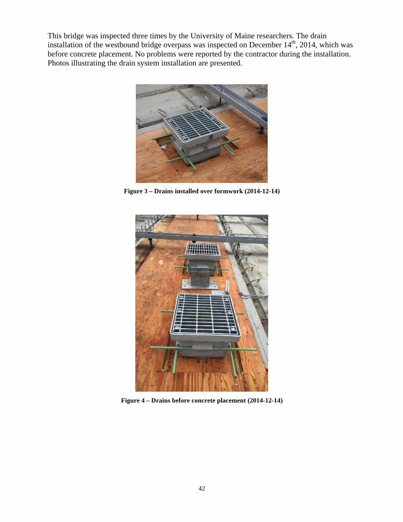
42
This bridge was inspected three times by the University of Maine researchers. The drain installation of the westbound bridge overpass was inspected on December 14th, 2014, which was before concrete placement. No problems were reported by the contractor during the installation. Photos illustrating the drain system installation are presented.
Figure 3 – Drains installed over formwork (2014-12-14)
Figure 4 – Drains before concrete placement (2014-12-14)

43
Figure 5 - Drain side detail (2014-12-14)
Figure 6 – Close-up of drain prior to concrete placement (2014-12-14)
Figure 7 – Detail of drain rebar attachment (2014-12-14)

44
Figure 8 – Drain side holes and rebar (2014-12-14)
Figure 9 - Drain grate (2014-12-14)
Figure 10 - Drain and formwork (2014-12-14)
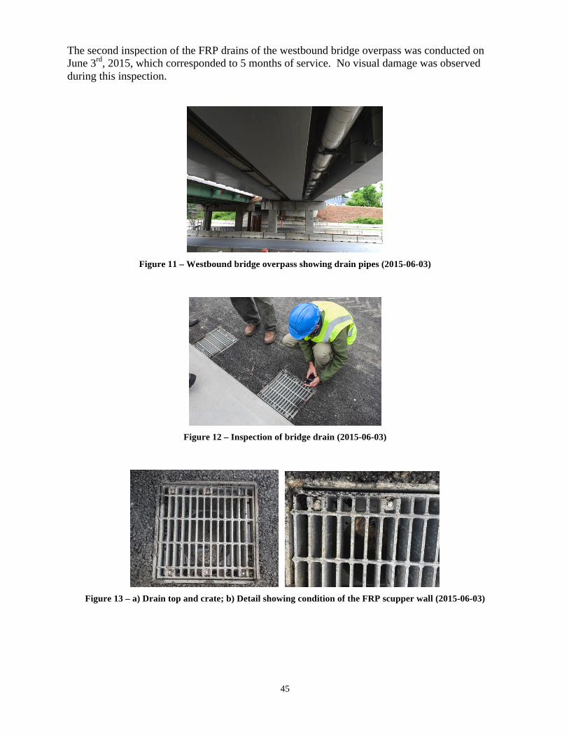
45
The second inspection of the FRP drains of the westbound bridge overpass was conducted on June 3rd, 2015, which corresponded to 5 months of service. No visual damage was observed during this inspection.
Figure 11 – Westbound bridge overpass showing drain pipes (2015-06-03)
Figure 12 – Inspection of bridge drain (2015-06-03)
Figure 13 – a) Drain top and crate; b) Detail showing condition of the FRP scupper wall (2015-06-03)
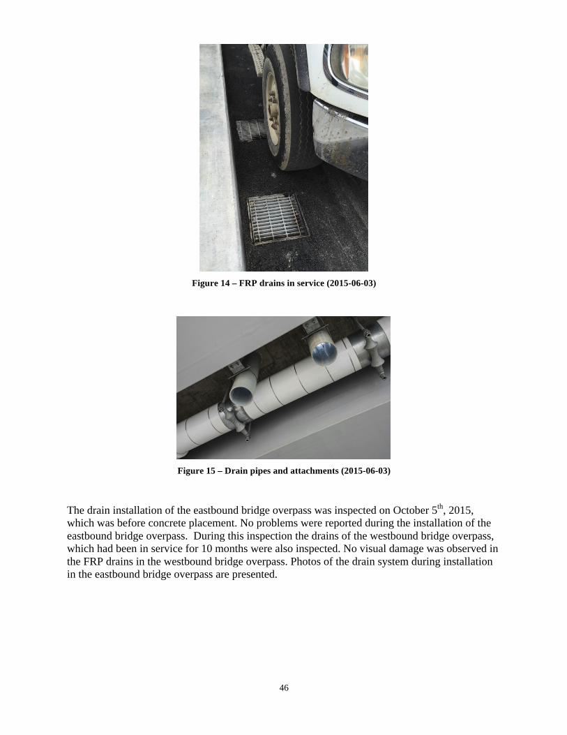
46
Figure 14 – FRP drains in service (2015-06-03)
Figure 15 – Drain pipes and attachments (2015-06-03)
The drain installation of the eastbound bridge overpass was inspected on October 5th, 2015, which was before concrete placement. No problems were reported during the installation of the eastbound bridge overpass. During this inspection the drains of the westbound bridge overpass, which had been in service for 10 months were also inspected. No visual damage was observed in the FRP drains in the westbound bridge overpass. Photos of the drain system during installation in the eastbound bridge overpass are presented.

47
Figure 16 - Eastbound bridge overpass during construction (2015-10-05)
Figure 17 – Drains and slab rebar prior to concrete placement (2015-10-05)
Figure 18 – Detail of grate and drain prior to concrete placement (2015-10-05)

48
Figure 19 – Drain pipe prior to concrete placement (2015-10-05)
Photos of the drain system after 10 months of service in the westbound bridge overpass are presented.
Figure 20 - Westbound bridge overpass after construction (2015-10-05)
Figure 21 – Drain pipes in the westbound bridge overpass (2015-10-05)

49
Figure 22 – Detail of drain pipe in the westbound bridge overpass (2015-10-05)
RICHMOND-DRESDEN BRIDGE, MAINE
Fiber reinforced polymer (FRP) bridge drains were used in the replacement of the bridge linking Richmond and Dresden over the Kennebec River in Fall 2014. This bridge project did not use the NETC FRP drain specifications and is presented as an example of existing technology. The bridge drains were inspected by the University of Maine researchers.
According to Assistant Engineer Devan Eaton, the cost of the FRP drains came to $4,000 per drain system. This included the galvanized steel grating and riser, FRP scupper and FRP downspout. The system was supplied by Eagle Manufacturing Co., Inc. of Salem, Connecticut. Eagle Manufacturing Co., Inc is predominantly a miscellaneous metals supplier and AISC shop for bridge components. They supplied the galvanized metal frame and grating for these drains. The FRP scupper and downspouts were manufactured by United Fiberglass in Springfield, OH, according to their General Manager Paul Harrington. United Fiberglass is a supplier of fiberglass bridge drain systems as well as FRP conduit and pipe. The contact information is: Paul Harrington – General Manager Eagle Manufacturing Co., Inc. 535 Hartford Rd. Salem, CT. 06420 Phone: 860.885.1563
United Fiberglass United Fiberglass of America 2145 Airpark Drive Springfield, OH 45502 Phone: 937.325.7305 and 888.939.5855
Figure 23- Drain Shop Drawing - Plan View

50
Figure 24 - Drain shop drawing – Sections
Photos illustrating the drain system installation are presented.
Figure 25 - Drain and slab rebar prior to concrete placement
Figure 26 – Close-up of drain prior to concrete placement
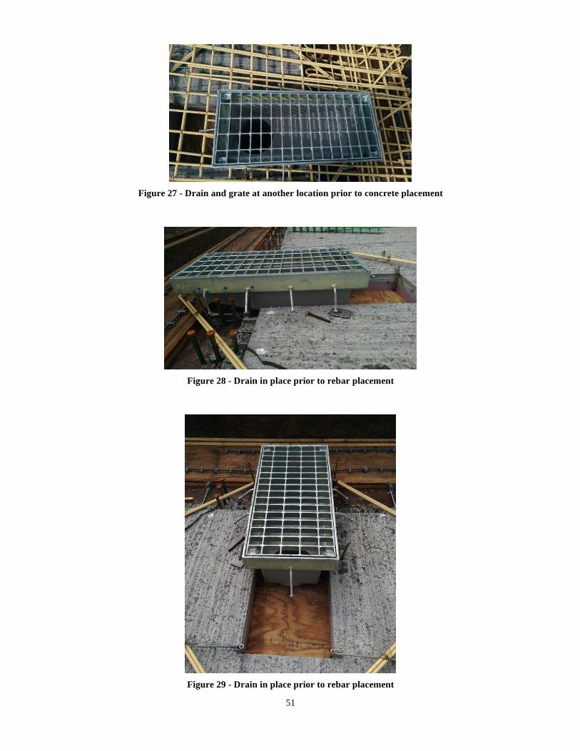
51
Figure 27 - Drain and grate at another location prior to concrete placement
Figure 28 - Drain in place prior to rebar placement
Figure 29 - Drain in place prior to rebar placement
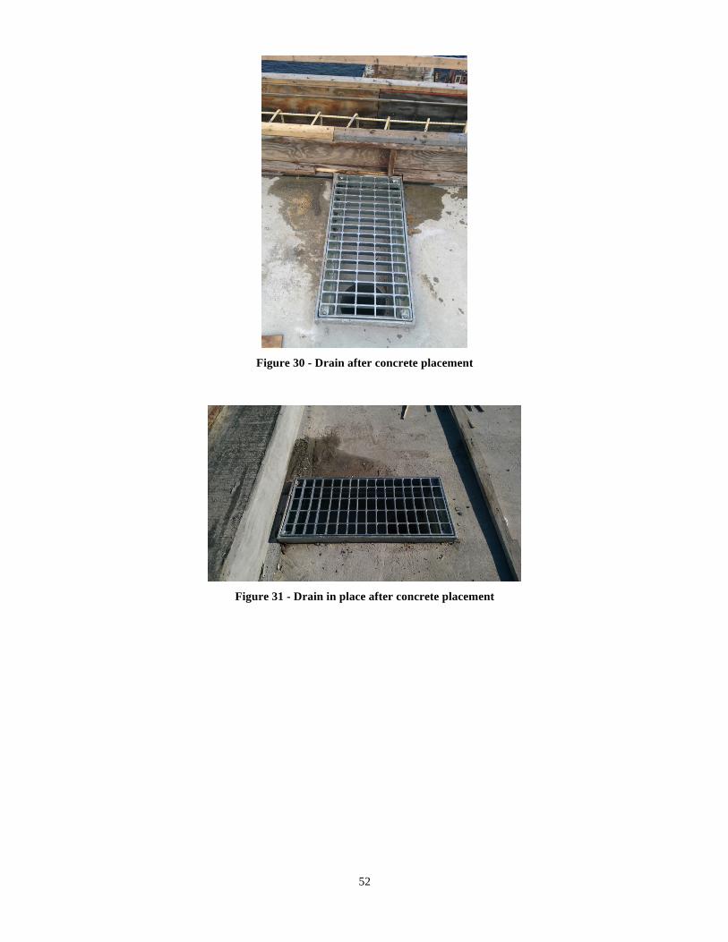
52
Figure 30 - Drain after concrete placement
Figure 31 - Drain in place after concrete placement

53
SUMMARY
A standard fiber-reinforced polymer (FRP) composite drain that can be produced economically for use throughout New England bridges was developed. The proposed standard FRP drain system can be used both for new construction and rehabilitation projects.
NETC FRP bridge drain details and specifications have been drafted and are available as part of Task 2 – Development of Standard Drain Requirements for New and Rehabilitation Projects, as follows:
• FRP Composite Bridge Drain Components Specification (page 12)• Appendix A: FRP Composite Drain and Pipe Material Requirements (page 18)• Appendix B: Preferred Inlet/Scupper Sizes And Overall Geometries (page 24)
Two FRP drain suppliers (A and B) provided composite material samples for testing and qualification for use in bridge drains according to Appendix A of the specification. This one time series of tests was conducted to ensure materials used would be durable and meet the requirements of bridge projects. The material coupons for the two suppliers met the specification criteria.
FRP drains were inspected on two bridge projects. One of these bridges, the Union Street Bridge in Bangor, ME, used the NETC FRP drain specifications. MaineDOT implemented the FRP bridge drain specifications developed in this NETC project for the Howland-Enfield Bridge; the corresponding shop drawings were presented.