advance mfg.co.,inc. · advance mfg.co.,inc. ... are capable of both clockwise and counter- ......
TRANSCRIPT
H y d r a u l i c To r q u e W r e n c H e s
c o m p u T e r i z e d To r q u i n g s y s T e m s
c a l i b r a T i o n e q u i p m e n T
AdvAnC e Mfg . Co., I nC .
S e r v i n g t h e g l o b a l M a r k e t p l a c e f o r o v e r 5 0 Y e a r S
AS9100
ISO 9001Registered
We have compiled this catalog to illustrate and define Advance
Mfg. Co., Inc’s hydraulic torque wrenches and associated products.
Designed for use on applications that require fastening or un-
fastening of threaded elements in aircraft engines, helicopters,
submarines, public utilities and construction industries. Advance
Mfg. Co., Inc wrenches fulfill any requirements dictated in the
precision assembly or disassembly of threaded components.
The products, outlined in this catalog have found worldwide
acceptance, with extensive use in the aircraft industry, on both
commercial and military jet engines. We certify the wrenches
for precise accuracy, within 3% of the full range of the wrench.
Each is equipped for easy visual checking of input torque values,
allowing the user to assure the correct torque value on the fastener.
Safe and simple to use, these wrenches completely eliminate
the strong-arm, backbreaking work currently required to
operate mechanical type torque multipliers: They can be used
to full capacity by using only fingertip control.
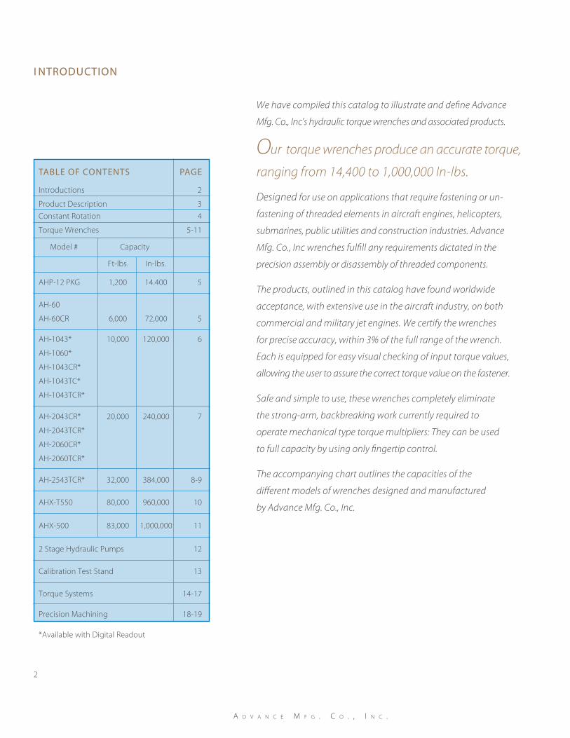
The accompanying chart outlines the capacities of the
different models of wrenches designed and manufactured
by Advance Mfg. Co., Inc.
i ntroduction
a d v a n c e M f g . c o . , i n c .
2
Our torque wrenches produce an accurate torque,
ranging from 14,400 to 1,000,000 In-lbs. table oF contentS page
Introductions 2
Product Description 3
Constant Rotation 4
Torque Wrenches 5-11
Model # Capacity
Ft-lbs. In-lbs.
AHP-12 PKG 1,200 14.400 5
AH-60
AH-60CR 6,000 72,000 5
AH-1043* 10,000 120,000 6
AH-1060*
AH-1043CR*
AH-1043TC*
AH-1043TCR*
AH-2043CR* 20,000 240,000 7
AH-2043TCR*
AH-2060CR*
AH-2060TCR*
AH-2543TCR* 32,000 384,000 8-9
AHX-T550 80,000 960,000 10
AHX-500 83,000 1,000,000 11
2 Stage Hydraulic Pumps 12
Calibration Test Stand 13
Torque Systems 14-17
Precision Machining 18-19
*Available with Digital Readout
S e r v i n g t h e g l o b a l M a r k e t p l a c e f o r o v e r 5 0 Y e a r S
3
Torque Wrenches
The torque wrenches described in this
catalog, with the exception of the AHX-T550,
are of the ratchet and pawl design, and
are capable of both clockwise and counter-
clockwise rotation without repositioning
the wrench on the application. The pawls,
which determine the direction of rotation
and the application of torque, are engaged
to the ratchet manually with a shifter that
is conveniently located on the face of the
wrench. Using fingertip control the operator
can easily shift the pawls (change direction),
allowing the operator to use the wrench to
its full capacity in the fastening application.
A directional valve mounted on the face of
the wrench controls fluid flow within each
wrench. This valve precisely controls the
rate at which the torque is applied, which
allows the operator to apply and hold the
exact torque requirements for the fastener
application. An electric, pneumatic, or a
hand pump supplies the hydraulic pressure.
The built in travel indicator allows the operator
to easily view the direction and amount of
rotation of the ratchet. There is also an angular
protractor mounted to the spline drive for
applications requiring a combination of
seating torque and final angle of turn.
The AHX-T550 model torque wrench has a
face type, hydraulically driven ratchet, which
will apply a torque in only one direction.
To obtain torque in the opposite direction,
it is necessary to turn the wrench over. This
wrench is specifically designed to quickly
remove (teardown) highly torqued fasten-
ers with complete safety. It has become the
“workhorse” of the aircraft industry, used
for quickly removing large turbine fasteners
with fingertip control.
The torque wrenches are listed in order of
their capacities. When selecting a wrench
for a particular application, remember that
the breakaway or teardown torque will be
larger, usually one and one half times more,
than the applied torque. The last number
designation in the model number, 43 or
60, designates the center drive configuration.
The number 43 denotes an S.A.E. 43 spline
(43 teeth) and 60 stands for an S.A.E. 60 spline
(32 teeth). You can order all the models as a
convenient package consisting of a storage
cart, wrench, supply hoses, and the proper
power source. The power source can be
either an electrical or a pneumatic drive.
If you require help in selecting a model
for your particular application, contact our
engineering department.
Torque wrenches designed and manufac-
tured by Advance Mfg. offer the mechanic
FULL CONTROL of torque application to
fasteners with only fingertip action, this
eliminates all the “strong arm” work currently
required to operate mechanical type torque
multipliers. Advance Mfg. calibrates and
certifies our wrenches for an accuracy of
within 3% of the wrenches full capacity.
All the pumps (hydraulic power sources)
in this catalog are either a pneumatic,
or an electric drive. They are all two-stage
operation, providing rapid approach, and
then automatically switching to a slower
more precise control.
Calibration Stand
Advance Mfg.’s hydraulic wrench calibration
test stands have become the standard in the
aircraft industry for certifying the accuracy
of high torquing wrenches. Calibration test
stands can be custom designed for any
torque range or required accuracy. Contact
our engineering department with your
requirements; they will be pleased to quote
on your application.
Torque Systems
Our new computerized torque systems offer
the latest in technology for blind torquing
of bolts in aircraft engine compressor rotor
drums. They are currently in service on many
of the latest high thrust jet engines in both
military and commercial applications. If you
have a blind torquing application requiring
precise, documented, torque control, contact
our engineering department to discuss
your requirements.
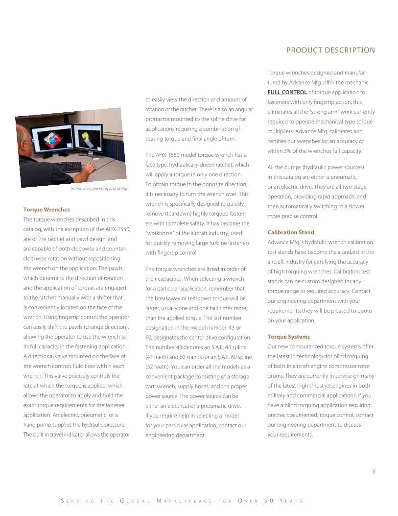
In-house engineering and design
product deScr i ption
Advance Mfg., the leader in high torque
fastening technology, introduces the fastest,
most accurate, torque wrench in the industry:
the innovative CONSTANT ROTATION system.
This system integrates the quick features of
mechanical “rundown” with the control and
precision of hydraulically actuated torquing.
With the CONSTANT ROTATION system the
operator can bottom large fasteners without
the use of large input to output mechanical
wrenches, which sometimes require 1200:1
ratios and transfer the input inaccuracies
to the output by a factor of the mechanical
ratios needed to deliver the required torques.
The system eliminates the need for large
mechanical wrenches that typically have
high ratios, costly reduction accessory units
and accompanying air drives needed to
facilitate speed in “rundown” of the fastener.
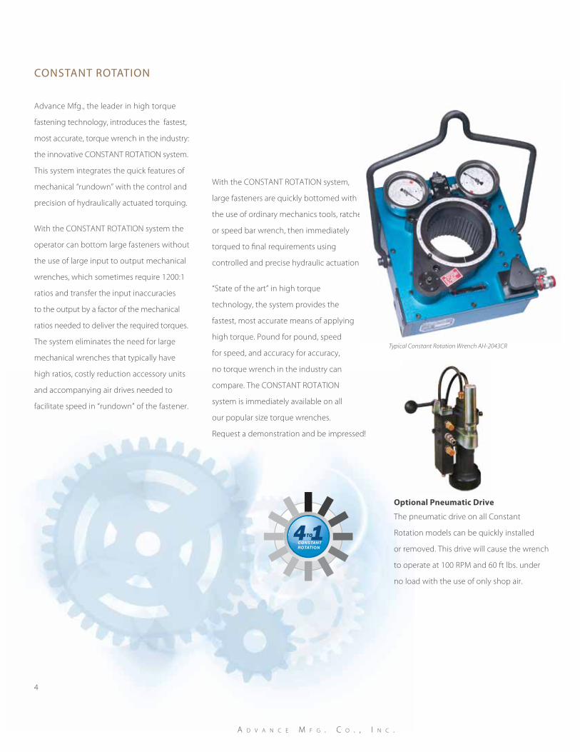
With the CONSTANT ROTATION system,
large fasteners are quickly bottomed with
the use of ordinary mechanics tools, ratchet
or speed bar wrench, then immediately
torqued to final requirements using
controlled and precise hydraulic actuation.
“State of the art” in high torque
technology, the system provides the
fastest, most accurate means of applying
high torque. Pound for pound, speed
for speed, and accuracy for accuracy,
no torque wrench in the industry can
compare. The CONSTANT ROTATION
system is immediately available on all
our popular size torque wrenches.
Request a demonstration and be impressed!
4
a d v a n c e M f g . c o . , i n c .
conStant rotation
optional Pneumatic drive
The pneumatic drive on all Constant
Rotation models can be quickly installed
or removed. This drive will cause the wrench
to operate at 100 RPM and 60 ft lbs. under
no load with the use of only shop air.
4TO 1CONSTANTROTATION
Typical Constant Rotation Wrench AH-2043CR
torque WrencheS
5
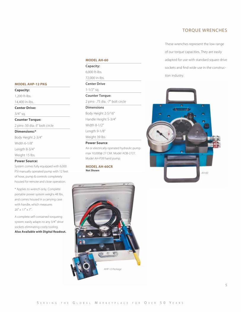
AHP-12 Package
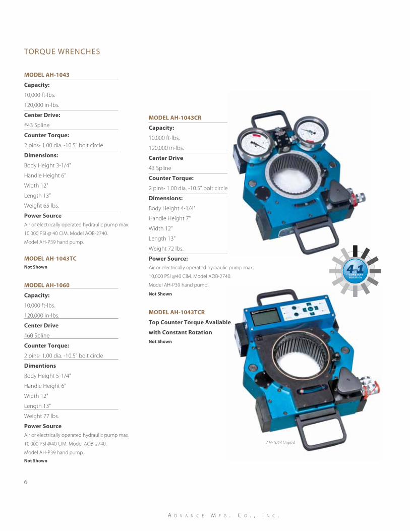
These wrenches represent the low range
of our torque capacities. They are easily
adapted for use with standard square drive
sockets and find wide use in the construc-
tion industry.
S e r v i n g t h e g l o b a l M a r k e t p l a c e f o r o v e r 5 0 Y e a r S
ModeL AH-60
Capacity:
6,000 ft-lbs.
72,000 in-lbs.
Center Drive
1-1/2" sq.
Counter Torque:
2 pins- .75 dia. -7" bolt circle
Dimensions
Body Height 2-5/16"
Handle Height 5-3/4"
Width 8-1/2"
Length 9-1/8"
Weight 39 lbs
Power SourceAir or electrically operated hydraulic pump
max 10,000@ 27 CIM. Model AOB-2727.
Model AH-P39 hand pump.
ModeL AHP-12 PKg
Capacity:
1,200 ft-lbs.
14,400 in-lbs.
Center drive:
3/4" sq.
Counter Torque:
2 pins-.50 dia.-3” bolt circle
dimensions:*
Body Height 2-3/4"
Width 6-1/8”
Length 8-3/4”
Weight 15 lbs.
Power Source:System comes fully equipped with 6,000
PSI manually operated pump with 12 feet
of hose, pump & controls completely
housed for remote and close operation.
* Applies to wrench only. Complete
portable power system weighs 48 lbs.
and comes housed in a carrying case
with handle, which measures
20” x 17” x 7”.
A complete self-contained torqueing
system; easily adapts to any 3/4” drive
sockets eliminating costly tooling.
Also Available with digital Readout.
ModeL AH-60CRnot Shown
AH-60
torque WrencheS
6
ModeL AH-1043
Capacity:
10,000 ft-lbs.
120,000 in-lbs.
Center drive:
#43 Spline
Counter Torque:
2 pins- 1.00 dia. -10.5" bolt circle
dimensions:
Body Height 3-1/4"
Handle Height 6"
Width 12"
Length 13"
Weight 65 lbs.
Power SourceAir or electrically operated hydraulic pump max.
10,000 PSI @ 40 CIM. Model AOB-2740.
Model AH-P39 hand pump.AH-1043
AH-1043 Digital
a d v a n c e M f g . c o . , i n c .
ModeL AH-1043CR
Capacity:
10,000 ft-lbs.
120,000 in-lbs.
Center drive
43 Spline
Counter Torque:
2 pins- 1.00 dia. -10.5" bolt circle
dimensions:
Body Height 4-1/4"
Handle Height 7"
Width 12"
Length 13"
Weight 72 lbs.
Power Source:Air or electrically operated hydraulic pump max.
10,000 PSI @40 CIM. Model AOB-2740.
Model AH-P39 hand pump.
not Shown
ModeL AH-1060
Capacity:
10,000 ft-lbs.
120,000 in-lbs.
Center drive
#60 Spline
Counter Torque:
2 pins- 1.00 dia. -10.5" bolt circle
dimentions
Body Height 5-1/4"
Handle Height 6"
Width 12"
Length 13"
Weight 77 lbs.
Power SourceAir or electrically operated hydraulic pump max.
10,000 PSI @40 CIM. Model AOB-2740.
Model AH-P39 hand pump.
not Shown
ModeL AH-1043TCnot Shown
ModeL AH-1043TCR
Top Counter Torque Available
with Constant Rotation not Shown
4TO 1CONSTANTROTATION
torque WrencheS
7
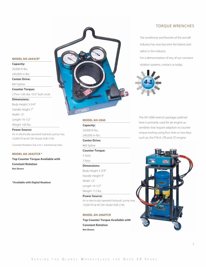
AH-2043CR
AH-2060 Package
The AH-2060 wrench package outlined
here is primarily used for jet engine as-
semblies that require adaption to counter
torque tooling using four slots or two keys
such as, the P.W.A. JT8 and JT3 engine
series’ applications.
S e r v i n g t h e g l o b a l M a r k e t p l a c e f o r o v e r 5 0 Y e a r S
ModeL AH-2043CR*
Capacity:
20,000 ft-lbs.
240,000 in-lbs.
Center drive:
#43 Spline
Counter Torque:
2 Pins-1.00 dia.-10.5" bolt circle
dimensions:
Body Height 3-3/4"
Handle Height 7"
Width 13"
Length 14-1/2"
Weight 100 lbs.
Power Source:Air or electrically operated hydraulic pump max.
10,000 PSI @ 40 CIM. Model AOB-2740.
Constant Rotation has 4 to 1 mechanical ratio.
ModeL AH-2043TCR *
Top Counter Torque Available with
Constant Rotationnot Shown
*Available with digital Readout
The workhorse and favorite of the aircraft
industry has now become the fastest and
safest in the industry.
For a demonstration of any of our constant
rotation systems, contact us today.
4TO 1CONSTANTROTATION
ModeL AH-2060
Capacity:
20,000 ft-lbs.
240,000 in-lbs.
Center drive:
#60 Spline
Counter Torque:
4 Slots
2 Keys
dimensions:
Body Height 5-3/4"
Handle Height 9"
Width 13"
Length 14-1/2"
Weight 112 lbs.
Power Source:Air or electrically operated hydraulic pump max.
10,000 PSI @ 40 CIM. Model AOB-2740.
ModeL AH-2060TCR
Top Counter Torque Available with
Constant Rotationnot Shown
8
torque WrencheS
In-house computerized inspection
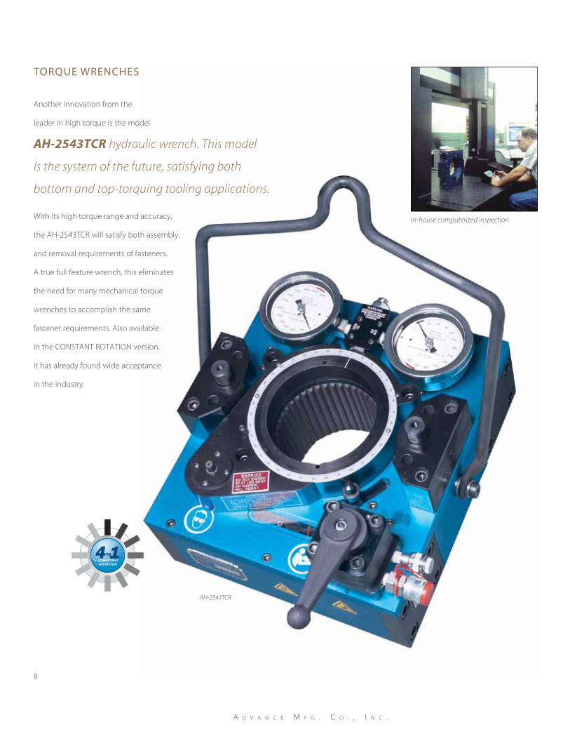
AH-2543TCR
a d v a n c e M f g . c o . , i n c .
Another innovation from the
leader in high torque is the model
With its high torque range and accuracy,
the AH-2543TCR will satisfy both assembly,
and removal requirements of fasteners.
A true full feature wrench, this eliminates
the need for many mechanical torque
wrenches to accomplish the same
fastener requirements. Also available
in the CONSTANT ROTATION version,
it has already found wide acceptance
in the industry.
AH-2543TCR hydraulic wrench. This model
is the system of the future, satisfying both
bottom and top-torquing tooling applications.
4TO 1CONSTANTROTATION
torque WrencheS
9
In-house computerized inspection
S e r v i n g t h e g l o b a l M a r k e t p l a c e f o r o v e r 5 0 Y e a r S
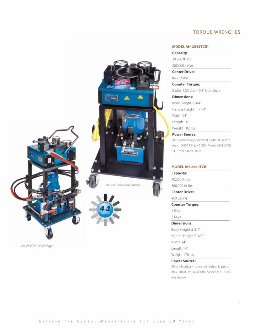
ModeL AH-2560TCR
Capacity:
30,000 ft-lbs.
360,000 in-lbs.
Center drive:
#60 Spline
Counter Torque:
4 Slots
2 Keys
dimensions:
Body Height 5-3/4"
Handle Height 9-1/4"
Width 14"
Length 14"
Weight 170 lbs.
Power Source:Air or electrically operated hydraulic pump
max. 10,000 PSI @ 40 CIM. Model AOB-2740.
Not Shown
ModeL AH-2543TCR*
Capacity:
30,000 ft-lbs.
360,000 in-lbs.
Center drive:
#43 Spline
Counter Torque:
2 pins-1.00 dia. -10.5" bolt circle
dimensions:
Body Height 7-3/4"
Handle Height 11-1/4"
Width 14"
Length 14"
Weight 182 lbs.
Power Source:Air or electrically operated hydraulic pump
max. 10,000 PSI @ 40 CIM. Model AOB-2740.
*4-1 mechanical ratio
AH-2543TCR Electrical Package
AH-2543TCR Air Package
4TO 1CONSTANTROTATION
torque WrencheS
10
a d v a n c e M f g . c o . , i n c .
AHX-T550
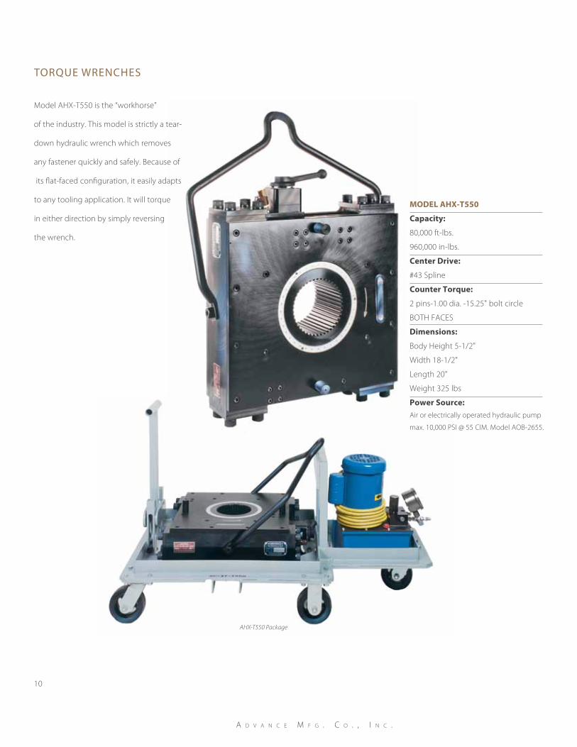
AHX-T550 Package
ModeL AHX-T550
Capacity:
80,000 ft-lbs.
960,000 in-lbs.
Center drive:
#43 Spline
Counter Torque:
2 pins-1.00 dia. -15.25" bolt circle
BOTH FACES
dimensions:
Body Height 5-1/2"
Width 18-1/2"
Length 20"
Weight 325 lbs
Power Source:Air or electrically operated hydraulic pump
max. 10,000 PSI @ 55 CIM. Model AOB-2655.
Model AHX-T550 is the “workhorse”
of the industry. This model is strictly a tear-
down hydraulic wrench which removes
any fastener quickly and safely. Because of
its flat-faced configuration, it easily adapts
to any tooling application. It will torque
in either direction by simply reversing
the wrench.
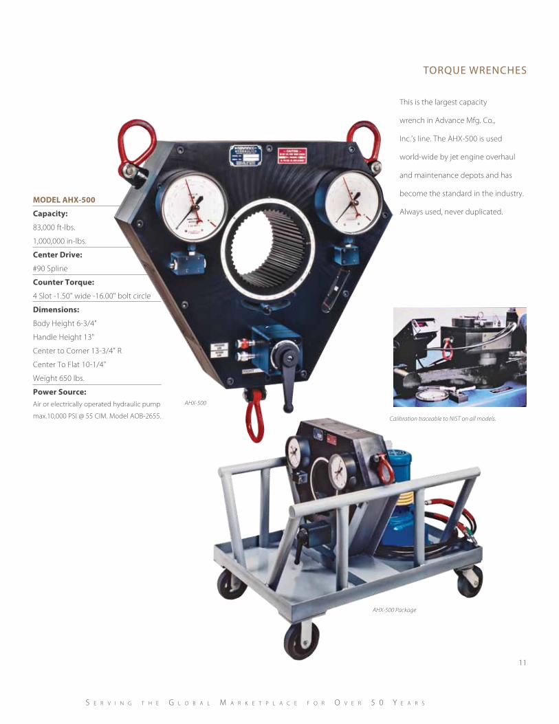
This is the largest capacity
wrench in Advance Mfg. Co.,
Inc.’s line. The AHX-500 is used
world-wide by jet engine overhaul
and maintenance depots and has
become the standard in the industry.
Always used, never duplicated.
torque WrencheS
11
Calibration traceable to NIST on all models.
S e r v i n g t h e g l o b a l M a r k e t p l a c e f o r o v e r 5 0 Y e a r S
ModeL AHX-500
Capacity:
83,000 ft-lbs.
1,000,000 in-lbs.
Center drive:
#90 Spline
Counter Torque:
4 Slot -1.50" wide -16.00" bolt circle
dimensions:
Body Height 6-3/4"
Handle Height 13"
Center to Corner 13-3/4" R
Center To Flat 10-1/4"
Weight 650 lbs.
Power Source:Air or electrically operated hydraulic pump
max.10,000 PSI @ 55 CIM. Model AOB-2655.
AHX-500
AHX-500 Package
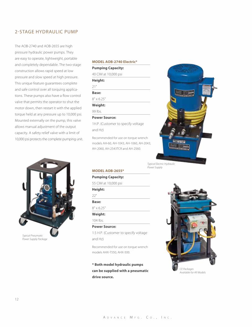
The AOB-2740 and AOB-2655 are high
pressure hydraulic power pumps. They
are easy to operate, lightweight, portable
and completely dependable. The two-stage
construction allows rapid speed at low
pressure and slow speed at high pressure.
This unique feature guarantees complete
and safe control over all torquing applica-
tions. These pumps also have a flow control
valve that permits the operator to shut the
motor down, then restart it with the applied
torque held at any pressure up to 10,000 psi.
Mounted externally on the pump, this valve
allows manual adjustment of the output
capacity. A safety relief valve with a limit of
10,000 psi protects the complete pumping unit.
2-Stage hydraulic pump
12
a d v a n c e M f g . c o . , i n c .
ModeL AoB-2740 electric*
Pumping Capacity:
40 CIM at 10,000 psi
Height:
21"
Base:
8" x 6.25"
Weight:
99 lbs.
Power Source:
1H.P. (Customer to specify voltage
and Hz)
Recommended for use on torque wrench
models AH-60, AH-1043, AH-1060, AH-2043,
AH-2060, AH-2543TCR and AH-2560.
ModeL AoB-2655*
Pumping Capacity:
55 CIM at 10,000 psi
Height:
22"
Base:
8" x 6.25"
Weight:
104 lbs.
Power Source:
1.5 H.P. (Customer to specify voltage
and Hz)
Recommended for use on torque wrench
models AHX-T550, AHX-500.
* Both model hydraulic pumps
can be supplied with a pneumatic
drive source.
Typical PneumaticPower Supply Package
Typical Electric Hydraulic Power Supply
CE Packages Available for All Models
cali bration teSt Stand
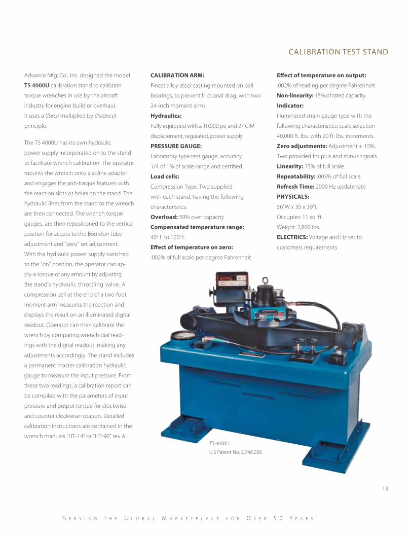
Advance Mfg. Co., Inc. designed the model
TS 4000U calibration stand to calibrate
torque wrenches in use by the aircraft
industry for engine build or overhaul.
It uses a (force multiplied by distance)
principle.
The TS 4000U has its own hydraulic
power supply incorporated on to the stand
to facilitate wrench calibration. The operator
mounts the wrench onto a spline adapter
and engages the anti-torque features with
the reaction slots or holes on the stand. The
hydraulic lines from the stand to the wrench
are then connected. The wrench torque
gauges, are then repositioned to the vertical
position for access to the Bourdon tube
adjustment and “zero” set adjustment.
With the hydraulic power supply switched
to the “on” position, the operator can ap-
ply a torque of any amount by adjusting
the stand’s hydraulic throttling valve. A
compression cell at the end of a two-foot
moment arm measures the reaction and
displays the result on an illuminated digital
readout. Operator can then calibrate the
wrench by comparing wrench dial read-
ings with the digital readout, making any
adjustments accordingly. The stand includes
a permanent master calibration hydraulic
gauge to measure the input pressure. From
these two readings, a calibration report can
be compiled with the parameters of input
pressure and output torque for clockwise
and counter clockwise rotation. Detailed
calibration instructions are contained in the
wrench manuals “HT-14” or “HT-90” rev A.
CALIBRATIon ARM:
Finest alloy steel casting mounted on ball
bearings, to prevent frictional drag, with two
24-inch moment arms.
Hydraulics:
Fully equipped with a 10,000 psi and 27 CIM
displacement, regulated, power supply.
PReSSuRe gAuge:
Laboratory type test gauge; accuracy
1/4 of 1% of scale range and certified.
Load cells:
Compression Type. Two supplied
with each stand, having the following
characteristics:
overload: 50% over capacity
Compensated temperature range:
400 F to 1200 F.
effect of temperature on zero:
.002% of full scale per degree Fahrenheit
effect of temperature on output:
.002% of reading per degree Fahrenheit
non-linearity: 15% of rated capacity.
Indicator:
Illuminated strain gauge type with the
following characteristics: scale selection
40,000 ft. lbs. with 20 ft. lbs. increments.
Zero adjustments: Adjustment + 15%.
Two provided for plus and minus signals.
Linearity: 15% of full scale.
Repeatability: .005% of full scale.
Refresh Time: 2000 Hz update rate
PHySICALS:
56”W x 35 x 30”L
Occupies: 11 sq. ft.
Weight: 2,800 lbs.
eLeCTRICS: Voltage and Hz set to
customers requirements
TS-4000U
U.S Patent No. 2,748,026
13
S e r v i n g t h e g l o b a l M a r k e t p l a c e f o r o v e r 5 0 Y e a r S

Since 1987, Advance Mfg. Co., Inc. Comput-
erized Torquing systems have provided the
ultimate turnkey solution to torque hidden
compressor rotor bolts in aircraft engines.
They guarantee compliance to engine
build specifications and provide full build
documentation.
The software manages the
process completely, which
eliminates the need for a
dedicated quality person
to validate the process steps
typically required for
torquing hidden fasteners.
The system is designed to meet particular
requirements set forth by engineers and
process planners: to achieve an effective tool
for creating a bolted joint having consistent
clamp characteristics, thus greatly reducing
engine vibration.
Consisting of logically stored tooling modules
that adapt to the compressor rotor assem-
blies, a computer driven Data Acquisition
Center, and a tool storage console, the system
also includes a remote calibration stand to
determine the mechanical efficiency of the
wrench system and to confirm the accuracy
and repeatability of the nut angle encoder.
The system is software driven and is
completely self-contained. The software en-
hances the system by providing the operator
with on line instructions and process-related
illustrations for the following tasks:
1. tool installation
2. tool removal
3. nut installation
4. calibration
5. engine requirements
6. torquing program
7. nut removal
8. engine disassembly
torque SyStemS
14
a d v a n c e M f g . c o . , i n c .
U.S. Patent #4,926,699 and other process and design patents.
Typical Tooling/Compressor Adaptor
If the engine’s build procedures change,
the displayed instructions can be edited
for process clarification, or for adding
associated illustrations.
The software also provides a tooling calibration
procedure, that presents the responsible
calibration authority with menu-driven
requirements for the entire tool calibration.
The calibration program is password pro-
tected to prevent unauthorized entry. The
torque program checks the stored calibration
results and time constraints from the last cal-
ibration. Only after successfully meeting these
calibration requirements will the program
allow entry into the engine build program.
The computer will routinely check the time
interval until the next calibration and will
prompt the operator for re-calibration when
this time interval reaches zero. The calibra-
tion interval can be increased or decreased
via the software to address a change in
production quota or build rates. The torque
program will be inoperable if calibration is
determined to be past its due date.
The system provides complete monitoring
for assembly and teardown torque require-
ments during the torque program. Upon re-
quest, the system can provide an actual run
time printing of all process events, parameters,
or tabular and graphics presentations.
The computer stores completed engine
build data that can be recalled at anytime.
Additionally, build data can be imported
from numerous engines into Microsoft
Excel® for further evaluation or for statistical
process control.
torque SyStemS
15
S e r v i n g t h e g l o b a l M a r k e t p l a c e f o r o v e r 5 0 Y e a r S
Remote SystemCalibration Stand
Logically Stored ToolingPositioned for Easy Access
ToolingStorage Console
12-Stage Tooling Module
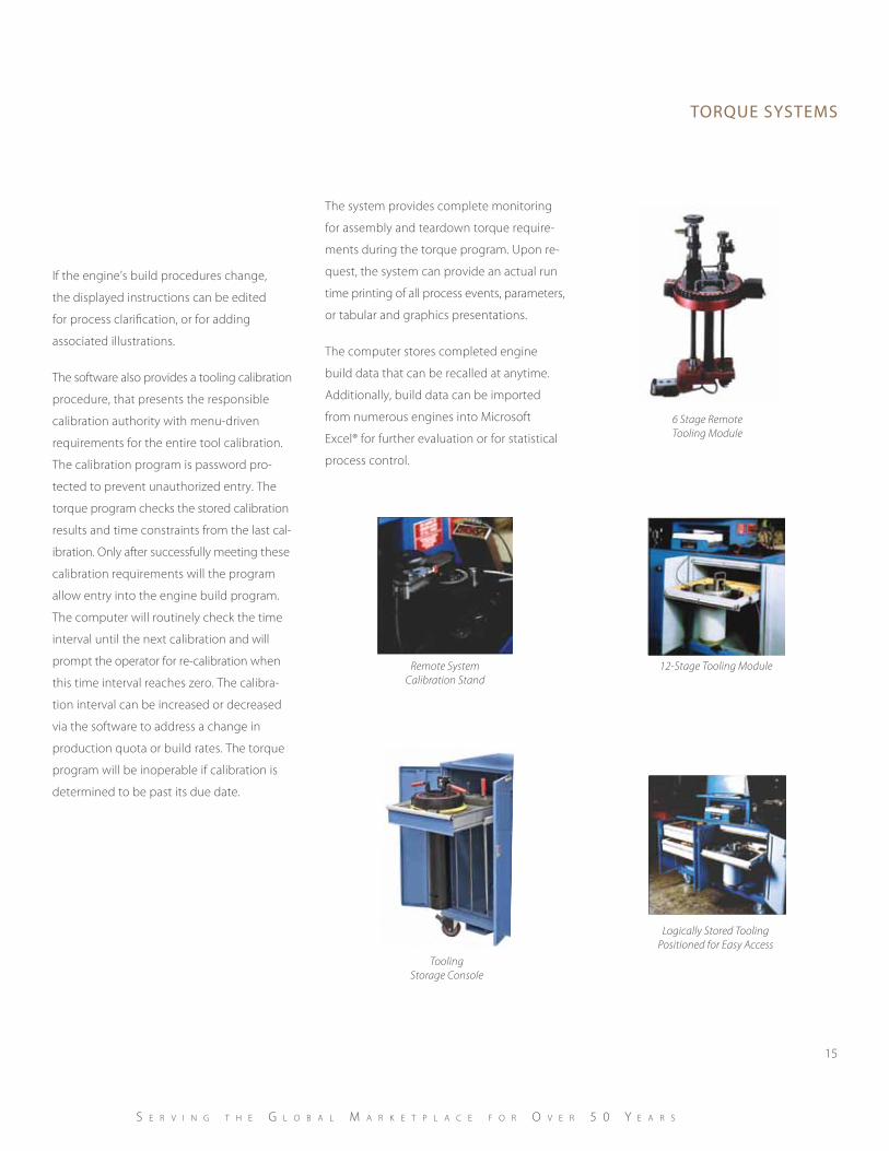
6 Stage RemoteTooling Module
In the event of a power failure, program
“retry” will allow the user to recommence
the build process at the previous recorded
process. No data will be lost.
Coupled with the mechanical tooling, the
AMD-109 Data Acquisition Center (DAC)
is a real time recipient of analog/digital
data transmitted by transducers and sensors
located on the tooling. The DAC and com-
puter can work together to create a multitask-
ing platform, where the DAC’s chief concern is
processing analog data, and the computer’s
chief concern is monitoring events. If a
process violation occurs, the computer will
signal the DAC to change its visual screen to
alert the user of the violation and to confirm
corrective actions. Native graphics screens
stored in eeprom allow the user to visually
identify the current process in digital form
along with the required limits. If a process
goes beyond the specified limits, a near
instantaneous display of a warning screen
will alert the user.
The DAC will receive the real time data
and convert it to proper engineering units
before displaying it on the user’s screen.
The engineering units, established by the
engine manufacturer, are not changeable
as they are hardwired into the software.
All software is custom written and adapted
to the engine manufacturer’s specific needs.
All manufacturers have methodically tested
the Data Acquisition Center and have en-
dorsed for production and overhaul use.
The DAC is responsible for displaying
the following process parameters:
• Installation Torque
• Prevailing Torque
• Initial Torque
• Seating Torque
• Angle (Nut Rotation)
• Current Bolt Location
The Industrial Computer is responsible for
doing such tasks as serial/parallel print
services and event (process) monitoring.
For simplicity and rock solid dependability,
a DOS operating system is used.
There are no requirements to know a
Windows® based OS or obtain third party
software drivers.
The computer displays the text in “mode
40” format to assist the user in seeing and
comprehending from a distance. This format
also ensures compatibility with our older sys-
tems throughout the world. The customer
receives a copy of the software for archiving
or, if necessary, for reloading the system via
the floppy drive.
torque SyStemS
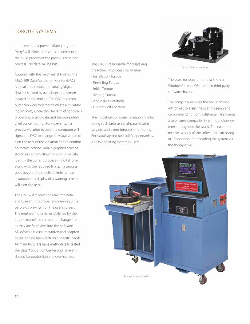
Typical Calibration Stand
Complete Torque System
16

torque SyStemS
Custom designed to address the need to
torque hidden nuts in compressor assem-
blies tooling is also logically stored in a roll
around cabinet, allowing it to be moved to
other areas on the build floor.
The tooling has 3 main functions.
1. Transmit a known input torque, via
manual means, to the fastener. A torque
transducer measures the applied input
torque. By multiplying the value for applied
input by the value for the mechanical
efficiency, established at calibration, the
operator can obtain a good, approximate
out put torque.
2. Angle of turn or nut angle is the most
important parameter supplied by the
tooling. This parameter contributes up
to 90% of the clamp load required and
is generally the preferred method used
by the engine manufacturer.
3. Bolt Location. The tooling will continuously
transmit its bolt location in relation to the
#1 start position. This position is crucial
for the success of the build session because
it will not allow the operator to skip or
miss a bolt. The software will dictate
the bolting sequence and will demand
conformation at all times.
The system has been approved for the
following engines.
3 All PW4000 series engines
3 All PW2000 series engines
3 All GP7200 series engines
3 All GE90 series engines
3 All GE CF6-80 and CF6-50 engine
3 All GE LM series engines
At Advance Mfg., Co., Inc., our goal is quality
customer satisfaction, and excellence in all
we do. We will always provide telephone/
email support at no charge to our customers.
We are an AS9100B Certified company.
SPeCIfICATIonS:
Torque Transducer Accuracy: .25% of
Full Scale. Temperature Compensated.
Angle encoder (Quadrature encoder):
.25 degree direct couple. +/- 1 degree using
software torsion correction.
Allowable Average gearbox efficiency
Range: 45% - 90%.
Typical gearbox efficiency Scatter @ 1
Standard deviation: < 5%.
Average gearbox efficiency
Repeatability: +/- 3% Typical
Typical User Screen
17
For over 50 years, Advance Mfg. Co., Inc. has
been one of the premiere manufacturers of
complex and simple parts in the country and
a significant, world-class competitor. From
precision machining to welded fabrication
to final assembly, our family-owned business
has focused on quality, customer satisfaction,
and excellence.
Throughout each process, we maintain
close attention to the project to ensure total
accuracy and top-notch results. Our state-of-
the-art, high-speed machining centers offer
twin spindles, 4th and 5th axis capabilities,
multiple pallets, and probing; our custom
tooling increases efficiency and provides
exacting results, even within the closest
tolerances.
The industries we work with include:
• Power Generation
• Aerospace
• Semiconductors
• Military
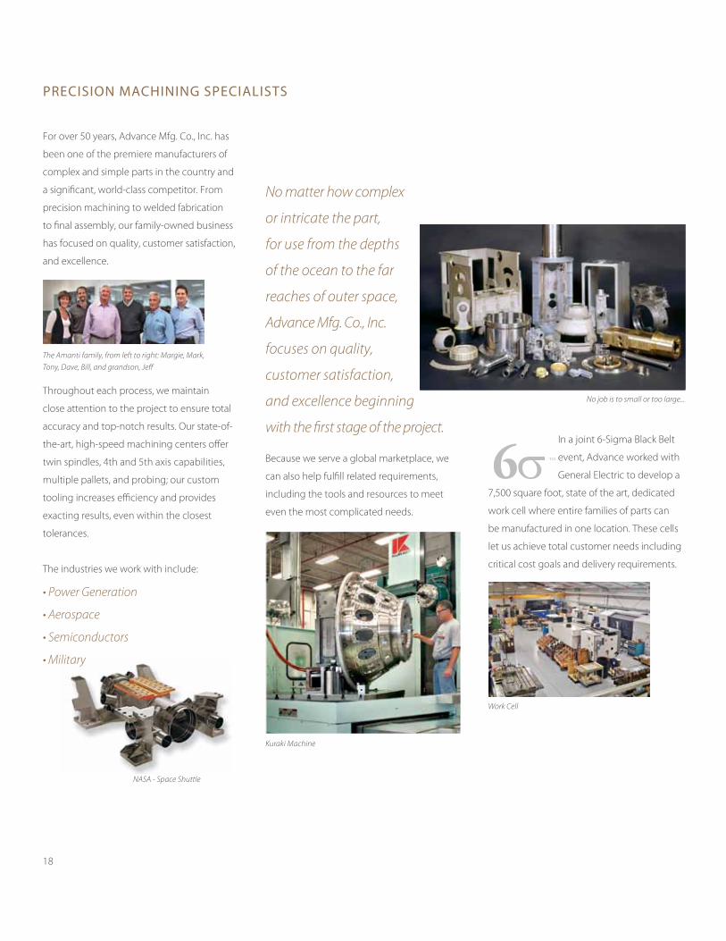
No matter how complex
or intricate the part,
for use from the depths
of the ocean to the far
reaches of outer space,
Advance Mfg. Co., Inc.
focuses on quality,
customer satisfaction,
and excellence beginning
with the first stage of the project.
Because we serve a global marketplace, we
can also help fulfill related requirements,
including the tools and resources to meet
even the most complicated needs.
In a joint 6-Sigma Black Belt
event, Advance worked with
General Electric to develop a
7,500 square foot, state of the art, dedicated
work cell where entire families of parts can
be manufactured in one location. These cells
let us achieve total customer needs including
critical cost goals and delivery requirements.
preciSion machining SpecialiStS
NASA - Space Shuttle
No job is to small or too large...
The Amanti family, from left to right: Margie, Mark,
Tony, Dave, Bill, and grandson, Jeff
Work Cell
Kuraki Machine
18
Advance houses conventional and wire cut-
ting machines, including one of the largest
cutting machines with a maximum capacity
of 47”x 31”x 15”.
For aerospace, commercial industries,
and the U.S Defense Department, Advance
is certified for MIG and TIG welding and
fabrication. Additionally, we have a Plasma-
Stellite machine which can hard-face parts
for power generation and other industries.
Our in house capabilities such as assembly,
outside processes, and shipping allow us
to guarantee quality service throughout
the entire process. To present exceptional
manufacturing in our facility, we have mul-
tiple Satellite Inspection Stations that enable
in-process inspection. This ensures that all
specifications are met with results that are
on point.
Our services include:
Jig Boring
Lapping and Grinding
OD/ID Grinding
Boring Mills
Vertical Milling
CNC Milling
Lathes
Vertical Turret Lathes
Manufacturing Cells
EDM
Honing
De-Burring & Aqueous Cleaning
Water Jet
Welding and Fabrication
Induction Heat Treating
Non-Destructive Testing
Inspection
Assembly
Outside Processes
Shipping
With a foundation built on quality work, we
are committed to maintain our reputation
for excellence. For more information on our
machining capabilities, please contact us for
our current catalogue or to set up a meeting
with a sales associate.
machining • Welded Fabrication • aSSemblieS
19
EDM
Plasma-Stellite Machine
Inspection Stations
Vacuum Pump
Assembly
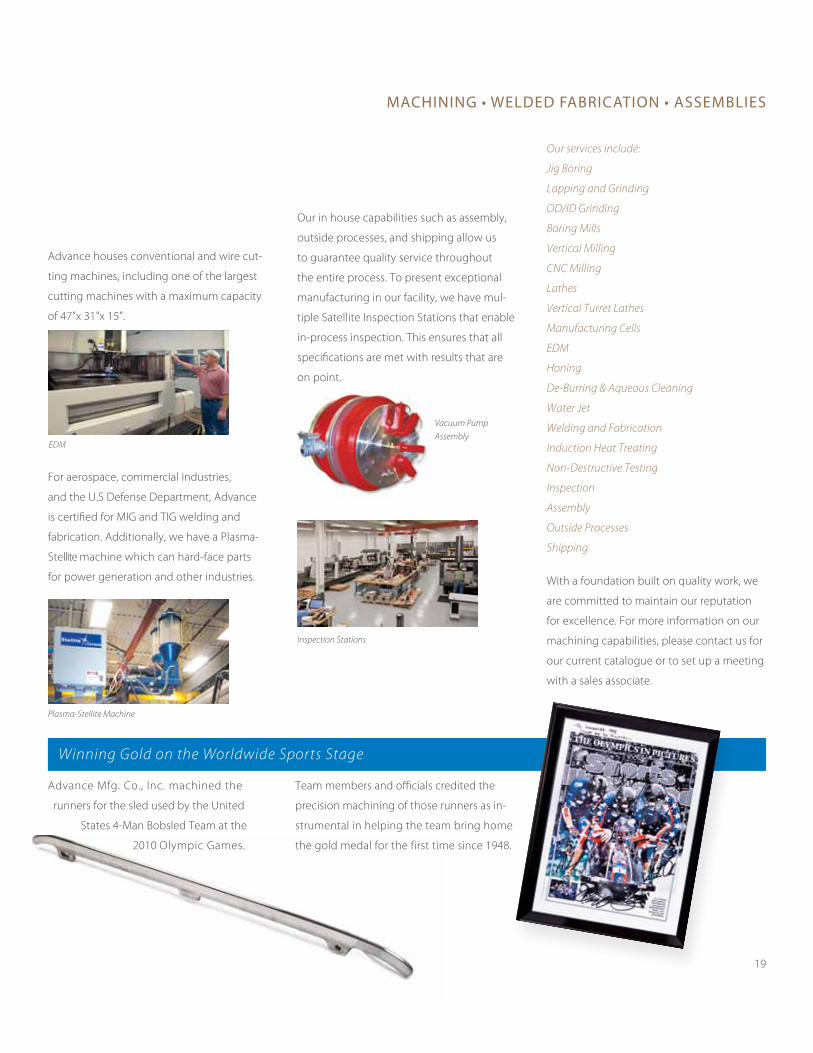
Advance Mfg. Co., Inc. machined the
runners for the sled used by the United
States 4-Man Bobsled Team at the
2010 Olympic Games.
Team members and officials credited the
precision machining of those runners as in-
strumental in helping the team bring home
the gold medal for the first time since 1948.
Winning Gold on the Worldwide Sports Stage
Tony E. Amanti founded Advance Mfg. Co.,
Inc. in 1961. Since that time the company
has become firmly established as a leading
manufacturer of mechanical and electro-
mechanical precision machined components
and assemblies.
Located in an area of New England that has
long been recognized for its knowledge and
expertise in the field of machining, Advance
has gathered an outstanding team of highly
skilled and professionally trained craftsmen,
which has resulted in the company’s strong,
steady growth.
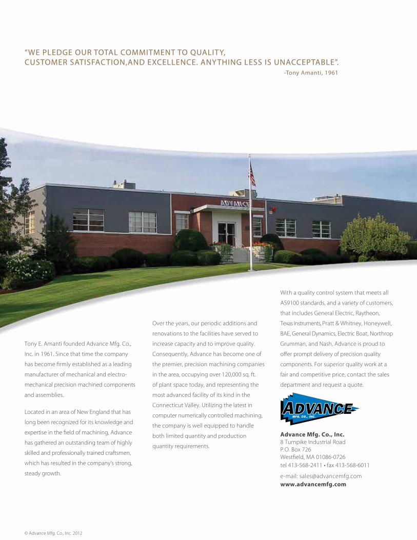
Over the years, our periodic additions and
renovations to the facilities have served to
increase capacity and to improve quality.
Consequently, Advance has become one of
the premier, precision machining companies
in the area, occupying over 120,000 sq. ft.
of plant space today, and representing the
most advanced facility of its kind in the
Connecticut Valley. Utilizing the latest in
computer numerically controlled machining,
the company is well equipped to handle
both limited quantity and production
quantity requirements.
With a quality control system that meets all
AS9100 standards, and a variety of customers,
that includes General Electric, Raytheon,
Texas Instruments, Pratt & Whitney, Honeywell,
BAE, General Dynamics, Electric Boat, Northrop
Grumman, and Nash, Advance is proud to
offer prompt delivery of precision quality
components. For superior quality work at a
fair and competitive price, contact the sales
department and request a quote.
Advance Mfg. Co., Inc.8 Turnpike Industrial Road P.O. Box 726Westfield, MA 01086-0726tel 413-568-2411 • fax 413-568-6011
e-mail: [email protected] www.advancemfg.com
“We pledge our total commitment to quality, cuStomer SatiSFaction,and excellence. anything leSS iS unacceptable”. -tony amanti, 1961
© Advance Mfg. Co., Inc. 2012