adsl 2/2+ 4-port router - planetplanet.com.tw/storage/products/2538/em-ade4400v5_v1.0.pdfcapability....
TRANSCRIPT

1
ADSL 2/2+ 4-port Router
ADE-4400

Copyright
Copyright 2011 by PLANET Technology Corp. All rights reserved. No part of this publication
may be reproduced, transmitted, transcribed, stored in a retrieval system, or translated into any
language or computer language, in any form or by any means, electronic, mechanical, magnetic,
optical, chemical, manual or otherwise, without the prior written permission of PLANET.
PLANET makes no representations or warranties, either expressed or implied, with respect to the
contents hereof and specifically disclaims any warranties, merchantability or fitness for any particular
purpose. Any software described in this manual is sold or licensed "as is". Should the programs
prove defective following their purchase, the buyer (and not this company, its distributor, or its dealer)
assumes the entire cost of all necessary servicing, repair, and any incidental or consequential damages
resulting from any defect in the software. Further, this company reserves the right to revise this
publication and to make changes from time to time in the contents hereof without obligation to notify
any person of such revision or changes.
All brand and product names mentioned in this manual are trademarks and/or registered trademarks
of their respective holders.
Federal Communication Commission Interference Statement
This equipment has been tested and found to comply with the limits for a Class B digital device,
pursuant to Part 15 of FCC Rules. These limits are designed to provide reasonable protection against
harmful interference in a residential installation. This equipment generates, uses, and can radiate
radio frequency energy and, if not installed and used in accordance with the instructions, may cause
harmful interference to radio communications. However, there is no guarantee that interference will
not occur in a particular installation. If this equipment does cause harmful interference to radio or
television reception, which can be determined by turning the equipment off and on, the user is
encouraged to try to correct the interference by one or more of the following measures:
1. Reorient or relocate the receiving antenna.
2. Increase the separation between the equipment and receiver.
3. Connect the equipment into an outlet on a circuit different from that to which the receiver is
connected.
4. Consult the dealer or an experienced radio technician for help.
FCC Caution
To assure continued compliance (example-use only shielded interface cables when connecting to
computer or peripheral devices). Any changes or modifications not expressly approved by the party
responsible for compliance could void the user’s authority to operate the equipment.
This device complies with Part 15 of the FCC Rules. Operation is subject to the Following two
conditions: (1) This device may not cause harmful interference, and (2) this Device must accept any
interference received, including interference that may cause undesired operation.
2
Federal Communication Commission (FCC) Radiation Exposure Statement
This equipment complies with FCC radiation exposure set forth for an uncontrolled environment. In
order to avoid the possibility of exceeding the FCC radio frequency exposure limits, human
proximity to the antenna shall not be less than 20 cm (8 inches) during normal operation.
R&TTE Compliance Statement
This equipment complies with all the requirements of DIRECTIVE 1999/5/EC OF THE
EUROPEAN PARLIAMENT AND THE COUNCIL OF 9 March 1999 on radio equipment and
telecommunication terminal Equipment and the mutual recognition of their conformity (R&TTE)
The R&TTE Directive repeals and replaces in the directive 98/13/EEC (Telecommunications
Terminal Equipment and Satellite Earth Station Equipment) As of April 8, 2000.
3
WEEE Regulation
To avoid the potential effects on the environment and human health as a result of the
presence of hazardous substances in electrical and electronic equipment, end users of
electrical and electronic equipment should understand the meaning of the crossed-out
wheeled bin symbol. Do not dispose of WEEE as unsorted municipal waste and have to collect such
WEEE separately.
Safety
This equipment is designed with the utmost care for the safety of those who install and use it.
However, special attention must be paid to the dangers of electric shock and static electricity when
working with electrical equipment. All guidelines of this and of the computer manufacture must
therefore be allowed at all times to ensure the safe use of the equipment.
Revision
User’s Manual for Wired ADSL 2/2+ Router
Model: ADE-4400v5
Rev: 1.0 (June. 2011)
Part No. EM-4400v5_v1

Table of Contents
1. INTRODUCTION ........................................................................................................................................... 7
1.1 Feature ................................................................................................................................. 7
1.2 Package Contents ................................................................................................................ 9
1.3 Physical Detail .................................................................................................................... 10
2. INSTALLATION ........................................................................................................................................... 12
2.1 System Requirement.......................................................................................................... 12
2.2 Hardware Installation.......................................................................................................... 12
2.3 Configuring the Network Properties ................................................................................... 13
3. WEB CONFIGURATION MANAGEMENT .................................................................................................. 17
3.1 Access the Router .............................................................................................................. 17
3.2 Wizard ................................................................................................................................ 18
3.3 Status ................................................................................................................................. 24
3.3.1System ...................................................................................................................................... 24
3.3.2 LAN .......................................................................................................................................... 24
3.3.3 WAN......................................................................................................................................... 24
3.3.4 Port Mapping............................................................................................................................ 25
3.3.5 Statistics ................................................................................................................................... 25
3.3.5.1 Traffic Statistic ............................................................................................................... 25
3.3.5.2 ADSL Statistic ................................................................................................................ 25
3.3.6 ARP Table................................................................................................................................ 26
3.4 Network .............................................................................................................................. 26
3.4.1 LAN .......................................................................................................................................... 26
3.4.1.1 LAN IP............................................................................................................................ 26
3.4.1.2 IPv6 LAN Config ............................................................................................................ 27
3.4.1.3 DHCP............................................................................................................................. 28
3.4.1.4 DHCP Static IP .............................................................................................................. 31
3.4.2 WAN......................................................................................................................................... 32
3.4.2.1 WAN............................................................................................................................... 32
3.4.2.2 ATM Setting ................................................................................................................... 34
3.4.2.3 ADSL Setting ................................................................................................................. 35
3.5 Service ............................................................................................................................... 36
4

3.5.1 DNS.......................................................................................................................................... 36
3.5.1.1 DNS ............................................................................................................................... 36
3.5.1.2 IPv6 DNS ....................................................................................................................... 37
3.5.1.3 DDNS............................................................................................................................. 37
3.5.2 Firewall ..................................................................................................................................... 38
3.5.2.1 IP Port Filter ................................................................................................................... 38
3.5.2.2 MAC Filter ...................................................................................................................... 39
3.5.2.3 URL Blocking ................................................................................................................. 39
3.5.2.4 Virtual Server ................................................................................................................. 40
3.5.2.5 DMZ Setting ................................................................................................................... 41
3.5.2.6 NAT EXCLUDE IP ......................................................................................................... 41
3.5.2.7 Anti-DoS Setting ............................................................................................................ 42
3.5.3 UPNP ....................................................................................................................................... 42
3.5.4 IGMP Proxy.............................................................................................................................. 42
3.5.5 TR-069 ..................................................................................................................................... 43
3.5.6 ACL .......................................................................................................................................... 44
3.6 Advance ............................................................................................................................. 45
3.6.1 Bridge Setting........................................................................................................................... 45
3.6.2 Routing..................................................................................................................................... 46
3.6.2.1 Static Route ................................................................................................................... 46
3.6.2.2 IPv6 Static Route ........................................................................................................... 47
3.6.2.3 RIP ................................................................................................................................. 48
3.6.3 Port Mapping............................................................................................................................ 49
3.6.4 QoS .......................................................................................................................................... 50
3.6.5 SNMP....................................................................................................................................... 51
3.6.6 Others....................................................................................................................................... 52
3.7 Admin ................................................................................................................................. 52
3.7.1 Commit/Reboot ........................................................................................................................ 52
3.7.2 Upgrade ................................................................................................................................... 52
3.7.2.1 Upgrade Firmware ......................................................................................................... 53
3.7.2.2 Backup/Restore ............................................................................................................. 53
3.7.3 System Log .............................................................................................................................. 54
3.7.4 Password ................................................................................................................................. 54
5

3.7.5 Time Zone ................................................................................................................................ 55
3.8 Diagnostic........................................................................................................................... 55
3.8.1 Ping .......................................................................................................................................... 55
3.8.2 Ping6 ........................................................................................................................................ 56
3.8.3 ATM Loopback ......................................................................................................................... 56
3.8.4 ADSL........................................................................................................................................ 56
3.8.5 Diagnostic Test ........................................................................................................................ 57
APPENDIX A: GLOSSARY ............................................................................................................................. 58
6
7
1. Introduction
The PLANET Wired ADSL 2/2+ Router, the ADE-4400, provides office and residential users
the ideal solution for sharing a High-Speed ADSL 2/2+ broadband Internet connection on
the 10/100Mbps Fast Ethernet Interface. It can support downstream transmission rates up
to 24Mbps and upstream transmission rates up to 3.5Mbps. The product supports PPPoA
(RFC 2364 - PPP over ATM Adaptation Layer 5), PPP over Ethernet (RFC 2516), and RFC
1483 encapsulation over ATM (MER, bridged or routed) to establish a connection with ISP.
Via the user-friendly management interface, the ADE-4400 can be managed by
workstations running standard web browsers. Furthermore, the device provides DHCP
server, NAT, Virtual Server, DMZ, access control, IP filter, VPN Pass-Through, and UPnP
capability.
The device also serves as an Internet firewall, protecting your network from being
accessed by outside users. It provides the natural firewall function (Network Address
Translation, NAT). All incoming and outgoing IPs are monitored and filtered by this product.
In addition, it can be configured to block internal users from accessing to the Internet.
1.1 Feature
Internet Access Features
Shared Internet Access All users on the LAN can access the Internet through the ADE-4400 using only a single external IP Address. The local (invalid) IP Addresses are hidden from external sources. This process is called NAT (Network Address Translation).
Built-in ADSL 2/2+ Modem
The device provides ADSL 2/2+ modem, and supports all common ADSL connections.
PPPoE, PPPoA, Direct Connection Support
Various WAN connections are supported by ADE-4400.
Auto-detection of Internet Connection Method
In most situations, the device can test your ADSL and Internet connection to determine the connection method used by your ISP.
Fixed or Dynamic IP Address
On the Internet (WAN port) connection, the device supports both Dynamic IP Address (IP Address is allocated on connection) and Fixed IP Address.

Advanced Internet Functions
Virtual Servers This feature allows Internet users to access Internet servers on your LAN. The required setup is quick and easy.
DMZ Support
The device can translate public IP addresses to private IP address to allow unrestricted 2-way communication with Servers or individual users on the Internet. This provides the most flexibility to run programs, which could be incompatible in NAT environment.
Firewall
Supports simple firewall with NAT technology and provides option for blocking access from Internet, like Web, FTP, Telnet, SNMP, and ICMP. It also supports MAC and IP filtering.
Universal Plug and Play (UPnP)
UPnP allows automatic discovery and configuration of the Broadband Router. UPnP is supported by Windows ME, XP, or later.
VPN Pass through Support
PCs with VPN (Virtual Private Networking) software are transparently supported - no configuration is required.
RIP1/2 Routing
It supports RIPv1/2 routing protocol for routing capability.
Simple Network Management Protocol (SNMP)
It is an easy way to remotely manage the router via SNMP.
LAN Features
Ethernet Port The ADE-4400 provides one Ethernet port, making it easy to create or extend your LAN.
4-Port Switch (ADE-4400 only)
The ADE-4400 incorporates a 4-Port 10/100Base-TX switching hub, making it easy to create or extend your LAN.
DHCP Server Support
Dynamic Host Configuration Protocol provides a dynamic IP address to PCs and other devices upon request. The device can act as a DHCP Server for devices on your local LAN.
8
1.2 Package Contents
‧ ADE-4400 Unit x 1
‧ Power Adapter x 1
‧ Quick Installation Guide x 1
‧ User’s Manual CD x 1
‧ RJ-11 cable x 2
‧ RJ-45 cable x 1
‧ Splitter x 1
9

1.3 Physical Detail
Front Panel of ADE-4400
Front Panel LED definition
LED State Description Green When the router is powered on and in ready state. Red The devise is being turned on and booting. PWR OFF When the router is powered off.
ON Successful connection between ADSL modem and telecom's network. Link
Flashing Modem is trying to establish a connection to telecom’s network.Data Flashing Data is transferred between Router and Internet.
ON Link LAN 1-4
Flashing TX or RX activity
10

Rear Panel of ADE-4400
Rear Panel Port and Button Definition
Connector Description
POWER Button The power button is for turn on or turns off the router.
Reset
The reset button can restore the default settings of device. To restore
factory defaults, keep the device powered on and push a paper clip into
the hole. Press down the button over 5 seconds and then release.
Power Power connector with 12V DC, 0.5A
LAN 1-4
Router is successfully connected to a device through the corresponding
port (1, 2, 3, or 4). If the LED is flashing, the Router is actively sending or
receiving data over that port.
Line The RJ-11 connector allows data communication between the modem
and the ADSL network through a twisted-pair phone wire.
11

2. Installation This chapter offers information about installing your router. If you are not familiar with the
hardware or software parameters presented here, please consult your service provider for
the values needed.
2.1 System Requirement
1. Personal computer (PC)
2. Pentium III 266 MHz processor or higher
3. 128 MB RAM minimum
4. 20 MB of free disk space minimum
5. RJ45 Ethernet Port
2.2 Hardware Installation
Please connect the device to you computer as follow:
If connecting to the splitter, connect the “Line” splitter to wall jack using one telephone cable
Use another telephone cable to connect “MODEM” port of the splitter and “LINE” port of the modem. The “Phone” port of the splitter can be use to connect the telephone by a telephone cable.
Use Ethernet cable to connect “LAN” port of the modem and “LAN” port of your computer.
Figure2 ADE-4400 connection diagram
If do not need to connect to the splitter,
12
Connect the modem to wall jack with a telephone cable.
Use Ethernet cable to connect “LAN” port of the modem and network adaptor of your computer.
2.3 Configuring the Network Properties
Configuring PC in Windows XP
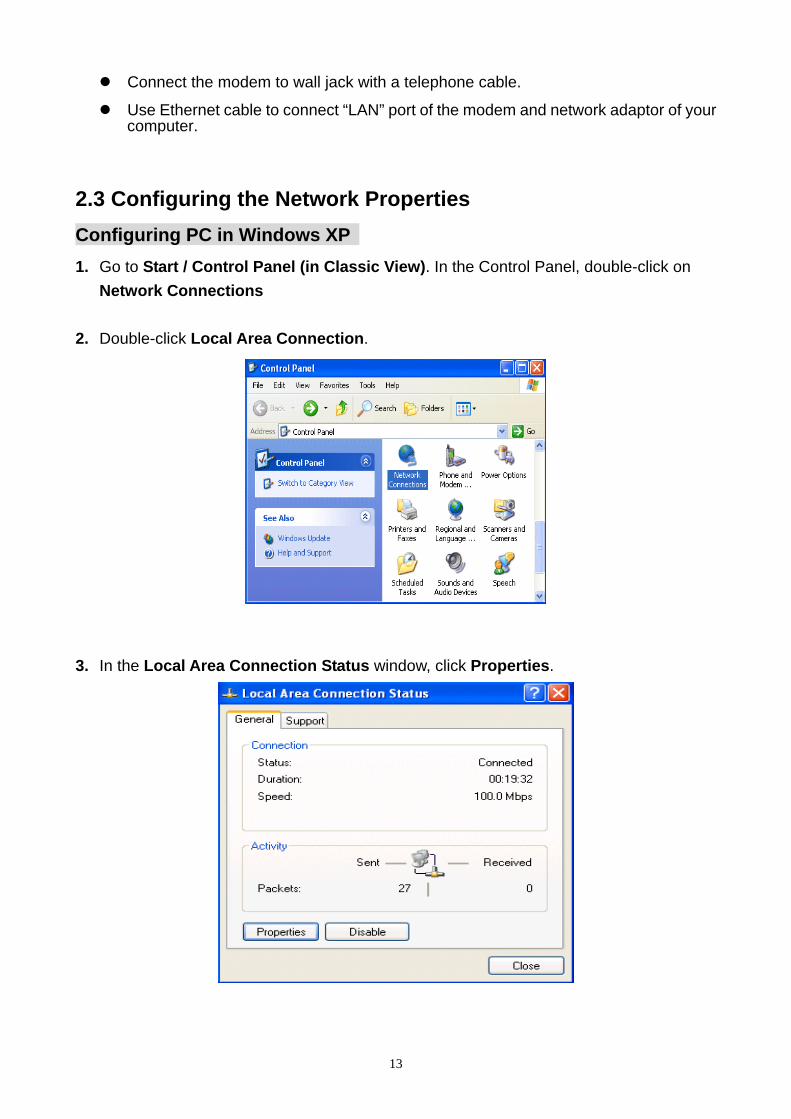
1. Go to Start / Control Panel (in Classic View). In the Control Panel, double-click on
Network Connections
2. Double-click Local Area Connection.
3. In the Local Area Connection Status window, click Properties.
13
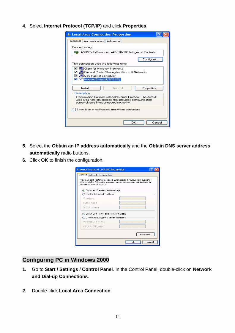
4. Select Internet Protocol (TCP/IP) and click Properties.
5. Select the Obtain an IP address automatically and the Obtain DNS server address
automatically radio buttons.
6. Click OK to finish the configuration.
Configuring PC in Windows 2000
1. Go to Start / Settings / Control Panel. In the Control Panel, double-click on Network
and Dial-up Connections.
2. Double-click Local Area Connection.
14
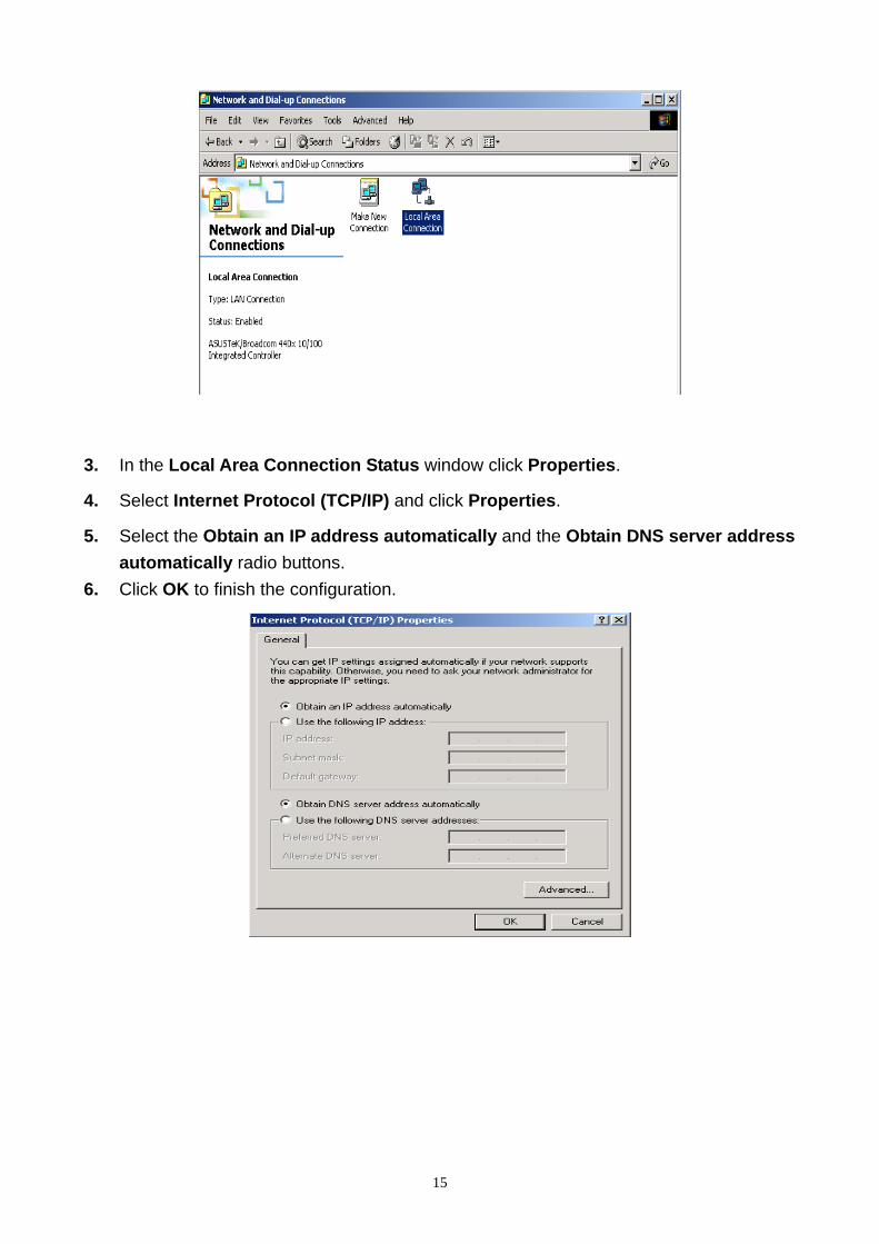
3. In the Local Area Connection Status window click Properties.
4. Select Internet Protocol (TCP/IP) and click Properties.
5. Select the Obtain an IP address automatically and the Obtain DNS server address
automatically radio buttons.
6. Click OK to finish the configuration.
15
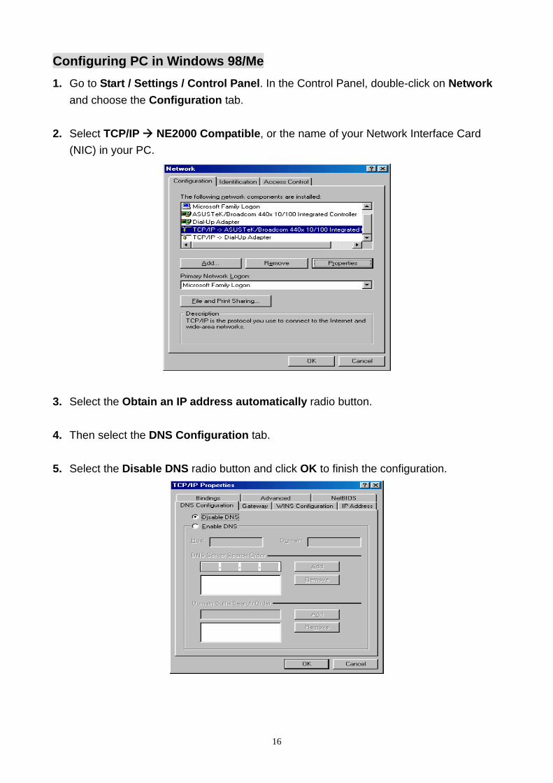
Configuring PC in Windows 98/Me
1. Go to Start / Settings / Control Panel. In the Control Panel, double-click on Network
and choose the Configuration tab.
2. Select TCP/IP NE2000 Compatible, or the name of your Network Interface Card
(NIC) in your PC.
3. Select the Obtain an IP address automatically radio button.
4. Then select the DNS Configuration tab.
5. Select the Disable DNS radio button and click OK to finish the configuration.
16

3. Web Configuration Management This chapter describes how to configure the router by using the Web-based configuration utility.
3.1 Access the Router
The following is the detailed description of accessing the router for the first time. Step 1 : Open the Internet Explorer (IE) browser and enter http://192.168.1.1. Step 2 : In the Login page that is displayed, enter the username and password. The username and password of the super user are admin and admin. The username and password of the common user are user and user.
If you log in as a super user, the page shown in the following figure appears. You can check, configure and modify all the settings.
If you log in as a common user, you can check the status of the router, but can not configure the most of the settings.
Note: In the Web configuration page, you can click Apply Changes to save the settings temporarily. If you want to save the settings of this page permanently, click save of Attention that appears at the button of the Web page after the configuration.
17

3.2 Wizard
The Wizard page guides fast and accurate configuration of the Internet connection and other important parameters. The following sections describe these various configuration parameters. Whether you configure these parameters or use the default ones, click NEXT to enable your Internet connection. When subscribing to a broadband service, you should be aware of the method by which you are connected to the Internet. Your physical WAN device can be either PPP, ADSL, or both. The technical information about the properties of your Internet connection is provided by your Internet Service Provider (ISP). For example, your ISP should inform you whether you are connected to the Internet using a static or dynamic IP address, and the protocol that you use to communicate on the Internet. In the navigation bar, click Wizard. The page shown in the following figure appears.
The following table describes the parameters of this page: Field Description
User Name Choose the user name for accessing the router. You can choose admin or user.
New Password Enter the password to which you want to change the old password. The password can not contain space key, %, “, ? or &.
Confirmed Password Enter the new password again.
After finishing the configuration, click NEXT. The page shown in the following figure appears. In this page, you can configure the system time and Network Time Protocol (NTP) server.
18
The following table describes the parameters of this page:
Field Description
State You can disable or enable NTP function. You have to enable it if you want to configure the parameters of this page.
Server IP Enter the IP address of the specified time server manually.
Interval Set the interval that the router obtains the time from the time server. That is, the interval that the router verifies the time with the server.
Time Zone Choose the time zone in which area you are from the drop down list.
GMT time It displays the Greenwich Mean Time (GMT).
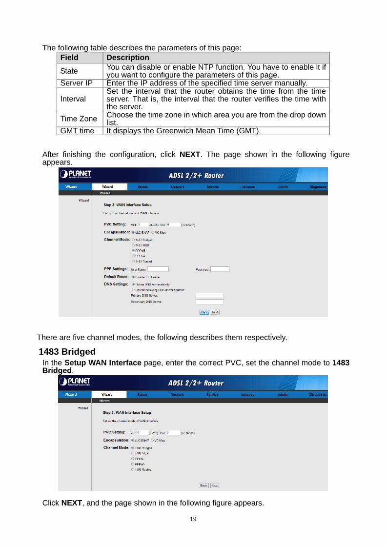
After finishing the configuration, click NEXT. The page shown in the following figure appears.
There are five channel modes, the following describes them respectively.
1483 Bridged In the Setup WAN Interface page, enter the correct PVC, set the channel mode to 1483 Bridged.
Click NEXT, and the page shown in the following figure appears.
19
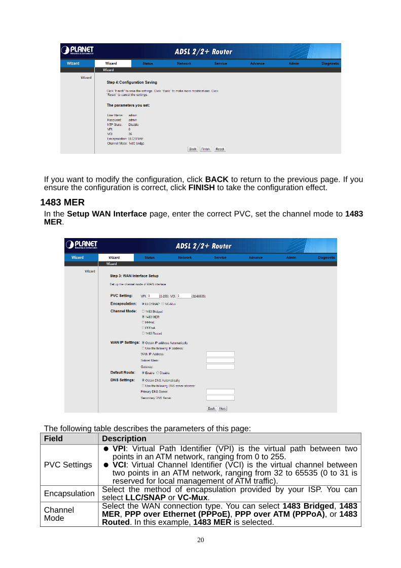
If you want to modify the configuration, click BACK to return to the previous page. If you ensure the configuration is correct, click FINISH to take the configuration effect.
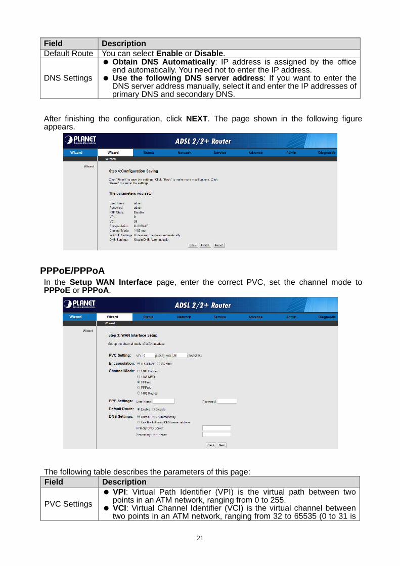
1483 MER In the Setup WAN Interface page, enter the correct PVC, set the channel mode to 1483 MER.
The following table describes the parameters of this page: Field Description
PVC Settings
VPI: Virtual Path Identifier (VPI) is the virtual path between two points in an ATM network, ranging from 0 to 255.
VCI: Virtual Channel Identifier (VCI) is the virtual channel between two points in an ATM network, ranging from 32 to 65535 (0 to 31 is reserved for local management of ATM traffic).
Encapsulation Select the method of encapsulation provided by your ISP. You can select LLC/SNAP or VC-Mux.
Channel Mode
Select the WAN connection type. You can select 1483 Bridged, 1483 MER, PPP over Ethernet (PPPoE), PPP over ATM (PPPoA), or 1483 Routed. In this example, 1483 MER is selected.
20
Field Description Default Route You can select Enable or Disable.
DNS Settings
Obtain DNS Automatically: IP address is assigned by the office end automatically. You need not to enter the IP address.
Use the following DNS server address: If you want to enter the DNS server address manually, select it and enter the IP addresses of primary DNS and secondary DNS.
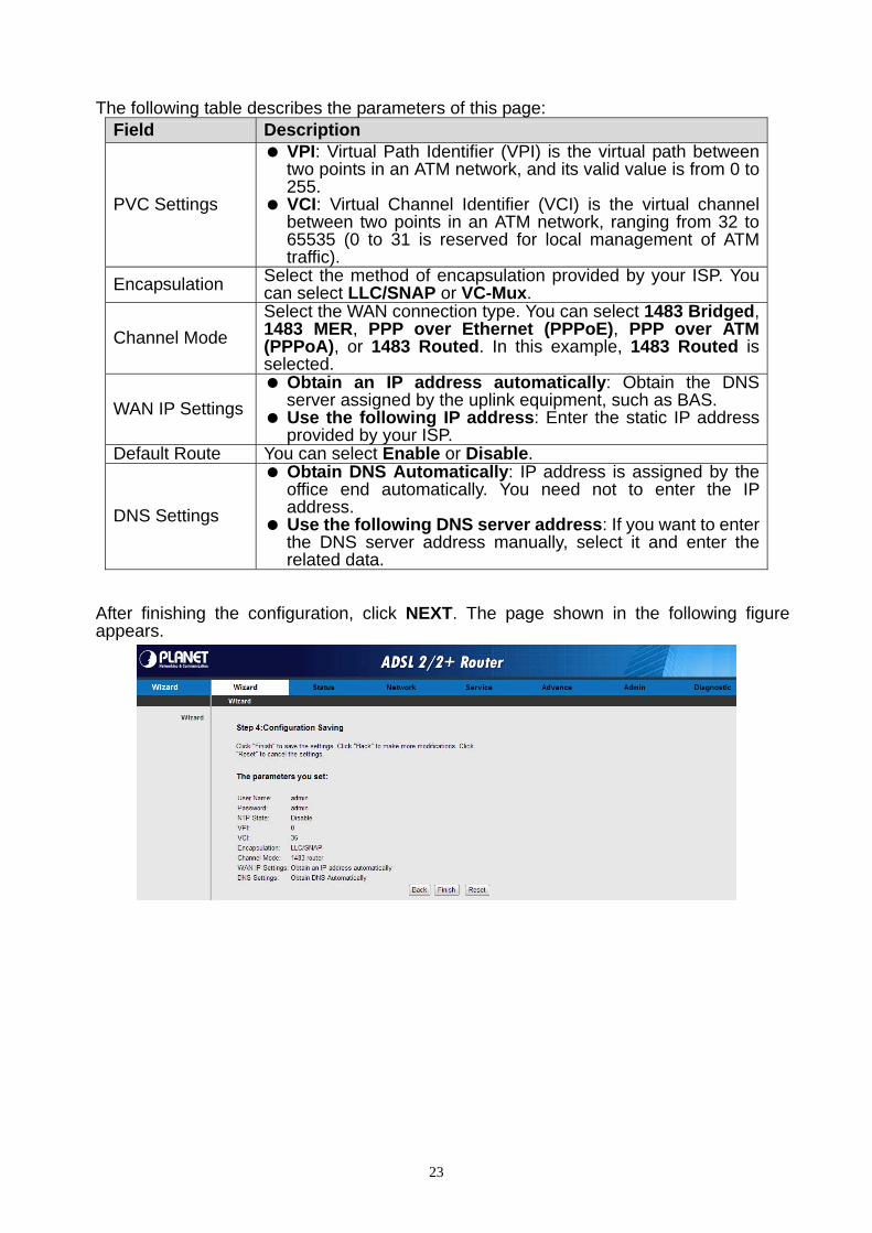
After finishing the configuration, click NEXT. The page shown in the following figure appears.
PPPoE/PPPoA In the Setup WAN Interface page, enter the correct PVC, set the channel mode to PPPoE or PPPoA.
The following table describes the parameters of this page: Field Description
PVC Settings
VPI: Virtual Path Identifier (VPI) is the virtual path between two points in an ATM network, ranging from 0 to 255.
VCI: Virtual Channel Identifier (VCI) is the virtual channel between two points in an ATM network, ranging from 32 to 65535 (0 to 31 is
21

Field Description reserved for local management of ATM traffic).
Encapsulation Select the method of encapsulation provided by your ISP. You can select LLC/SNAP or VC-Mux.
Channel Mode
Select the WAN connection type. You can select 1483 Bridged, 1483 MER, PPP over Ethernet (PPPoE), PPP over ATM (PPPoA), or 1483 Routed. In this example, PPPoE is selected.
PPP Settings Enter the username and password for PPP dial-up, which are provided by your ISP.
Default Route You can select Enable or Disable.
DNS Settings
Obtain DNS Automatically: IP address is assigned by the office end automatically. You need not to enter the IP address.
Use the following DNS server address: If you want to enter the DNS server address manually, select it and enter the IP addresses of primary DNS and secondary DNS.
After finishing the configuration, click NEXT. The page shown in the following figure appears.
1483 Routed In the Setup WAN Interface page, enter the correct PVC, set the channel mode to 1483 Routed.
22
The following table describes the parameters of this page:
Field Description
PVC Settings
VPI: Virtual Path Identifier (VPI) is the virtual path between two points in an ATM network, and its valid value is from 0 to 255.
VCI: Virtual Channel Identifier (VCI) is the virtual channel between two points in an ATM network, ranging from 32 to 65535 (0 to 31 is reserved for local management of ATM traffic).
Encapsulation Select the method of encapsulation provided by your ISP. You can select LLC/SNAP or VC-Mux.
Channel Mode
Select the WAN connection type. You can select 1483 Bridged, 1483 MER, PPP over Ethernet (PPPoE), PPP over ATM (PPPoA), or 1483 Routed. In this example, 1483 Routed is selected.
WAN IP Settings
Obtain an IP address automatically: Obtain the DNS server assigned by the uplink equipment, such as BAS.
Use the following IP address: Enter the static IP address provided by your ISP.
Default Route You can select Enable or Disable.
DNS Settings
Obtain DNS Automatically: IP address is assigned by the office end automatically. You need not to enter the IP address.
Use the following DNS server address: If you want to enter the DNS server address manually, select it and enter the related data.
After finishing the configuration, click NEXT. The page shown in the following figure appears.
23

3.3 Status
In the navigation bar, click Status. In the Status page that is displayed contains System, LAN, WAN, Statistics and ARP Table.
3.3.1System
Choose Status > System. The page that is displayed shows the current status and some basic settings of the router, such as, uptime, software version, upstream speed, downstream speed, and other information.
3.3.2 LAN
Choose Status > LAN. The page that is displayed shows some basic LAN settings of the router. In the LAN Status page, you can view the LAN IP address, DHCP server status, MAC address and DHCP client table. If you want to configure the LAN network, refer to the chapter 03.4.1 LAN.
3.3.3 WAN
Choose Status > WAN. The page that is displayed shows some basic WAN settings of the router. In the WAN Status page, you can view basic status of WAN, default gateway, DNS server. If you want to configure the WAN network, refer to the chapter 03.4.2 WAN.
24

3.3.4 Port Mapping Choose Status > Port Mapping. The page that is displayed shows the relationship and status of port mapping.
3.3.5 Statistics
Choose Status > Statistics. The Statistics page that is displayed contains Traffic Statistic and DSL Statistic.
3.3.5.1 Traffic Statistic
Click Traffic Statistic in the left pane, the page shown in the following figure appears. In this page, you can view the statistics of each network interface.
3.3.5.2 ADSL Statistic
Click DSL Statistic in the left pane, the page shown in the following figure appears. In this page, you can view the ADSL line statistics, downstream rate, upstream rate and other information.
25

3.3.6 ARP Table
Choose Status > ARP Table. In the Arp tables page, you can view the table that shows a list of learned MAC addresses.
3.4 Network
In the navigation bar, click Network. The Network page that is displayed contains LAN and WAN.
3.4.1 LAN
Choose Network > LAN. The LAN page that is displayed contains LAN IP, DHCP, and DHCP Static IP.
3.4.1.1 LAN IP
Click LAN IP in the left pane, the page shown in the following figure appears. In this page, you can change IP address of the router. The default IP address is 192.168.1.1, which is the private IP address of the router.
26
The following table describes the parameters of this page:
Field Description
IP Address
Enter the IP address of LAN interface. It is recommended to use an address from a block that is reserved for private use. This address block is 192.168.1.1- 192.168.255.254.
Subnet Mask Enter the subnet mask of LAN interface. The range of subnet mask is from 255.255.0.0-255.255.255.254.
Secondary IP Select it to enable the secondary LAN IP address. The two LAN IP addresses must be in the different network.
Link Speed/Duplex Mode Select the Link Speed/Duplex Mode which you need.
ETHERNET Status Table This table will show the current link mode for every port.
MAC Address Control If you want to use the MAC address control feature, select it and add the MAC address.
New MAC Address Add the MAC address which you want can access the router via the LAN port.
Current Allowed MAC Address Table
This table will show the current allowed MAC address .
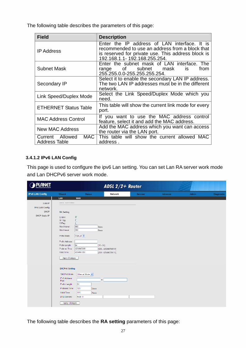
3.4.1.2 IPv6 LAN Config
This page is used to configure the ipv6 Lan setting. You can set Lan RA server work mode
and Lan DHCPv6 server work mode.
The following table describes the RA setting parameters of this page:
27
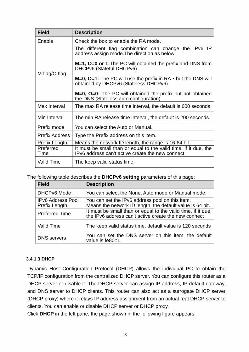
Field Description
Enable Check the box to enable the RA mode.
M flag/O flag
The different flag combination can change the IPv6 IP address assign mode.The direction as below: M=1, O=0 or 1:The PC will obtained the prefix and DNS from DHCPv6 (Stateful DHCPv6) M=0, O=1: The PC will use the prefix in RA,but the DNS will obtained by DHCPv6 (Stateless DHCPv6) M=0, O=0: The PC will obtained the prefix but not obtained the DNS (Stateless auto configuration)
Max Interval The max RA release time interval, the default is 600 seconds.
Min Interval The min RA release time interval, the default is 200 seconds.
Prefix mode You can select the Auto or Manual.
Prefix Address Type the Prefix address on this item.
Prefix Length Means the network ID length, the range is 16-64 bit. Preferred Time
It must be small than or equal to the valid time, if it due, the IPv6 address can’t active create the new connect
Valid Time The keep valid status time.
The following table describes the DHCPv6 setting parameters of this page:
Field Description
DHCPv6 Mode You can select the None, Auto mode or Manual mode.
IPv6 Address Pool You can set the IPv6 address pool on this item. Prefix Length Means the network ID length, the default value is 64 bit.
Preferred Time It must be small than or equal to the valid time, if it due, the IPv6 address can’t active create the new connect
Valid Time The keep valid status time, default value is 120 seconds
DNS servers You can set the DNS server on this item, the default value is fe80::1.
3.4.1.3 DHCP
Dynamic Host Configuration Protocol (DHCP) allows the individual PC to obtain the
TCP/IP configuration from the centralized DHCP server. You can configure this router as a
DHCP server or disable it. The DHCP server can assign IP address, IP default gateway,
and DNS server to DHCP clients. This router can also act as a surrogate DHCP server
(DHCP proxy) where it relays IP address assignment from an actual real DHCP server to
clients. You can enable or disable DHCP server or DHCP proxy.
Click DHCP in the left pane, the page shown in the following figure appears.
28
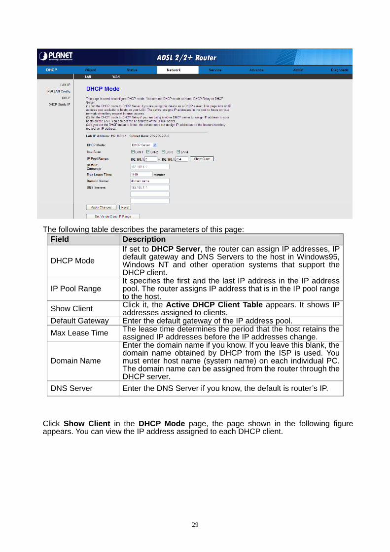
The following table describes the parameters of this page: Field Description
DHCP Mode
If set to DHCP Server, the router can assign IP addresses, IP default gateway and DNS Servers to the host in Windows95, Windows NT and other operation systems that support the DHCP client.
IP Pool Range It specifies the first and the last IP address in the IP address pool. The router assigns IP address that is in the IP pool range to the host.
Show Client Click it, the Active DHCP Client Table appears. It shows IP addresses assigned to clients.
Default Gateway Enter the default gateway of the IP address pool.
Max Lease Time The lease time determines the period that the host retains the assigned IP addresses before the IP addresses change.
Domain Name
Enter the domain name if you know. If you leave this blank, the domain name obtained by DHCP from the ISP is used. You must enter host name (system name) on each individual PC. The domain name can be assigned from the router through the DHCP server.
DNS Server Enter the DNS Server if you know, the default is router’s IP.
Click Show Client in the DHCP Mode page, the page shown in the following figure appears. You can view the IP address assigned to each DHCP client.
29

The following table describes the parameters and buttons in this page: Field Description
IP Address It displays the IP address assigned to the DHCP client from the router.
MAC Address
It displays the MAC address of the DHCP client. Each Ethernet device has a unique MAC address. The MAC address is assigned at the factory and it consists of six pairs of hexadecimal character, for example, 00-A0-C5-00-02-12.
Expired (s) It displays the lease time. The lease time determines the period that the host retains the assigned IP addresses before the IP addresses change.
Refresh Click it to refresh this page. Close Click it to close this page.
Click Set VendorClass IP Range in the DHCP Mode page, the page shown in the following figure appears. You can view the IP address assigned to each DHCP client. The following table describes the parameters and buttons in this page:
Field Description Device Name You can set the device name on this item. Start Address The IP address range start address. End Address The IP address range end address. Router Address Set the router address on this item Option60 Type the Option60 value.
In the DHCP Mode field, choose None. The page shown in the following figure appears.
30

In the DHCP Mode field, choose DHCP Relay. The page shown in the following figure appears.
The following table describes the parameters and buttons of this page:
Field Description
DHCP Mode
If set to DHCP Relay, the router acts a surrogate DHCP Server and relays the DHCP requests and responses between the remote server and the client.
Relay Server Enter the DHCP server address provided by your ISP.
Apply Changes Click it to save the settings of this page. Undo Click it to refresh this page.
3.4.1.4 DHCP Static IP
Click DHCP Static IP in the left pane, the page shown in the following figure appears. You can assign the IP addresses on the LAN to the specific individual PCs based on their MAC address.
31
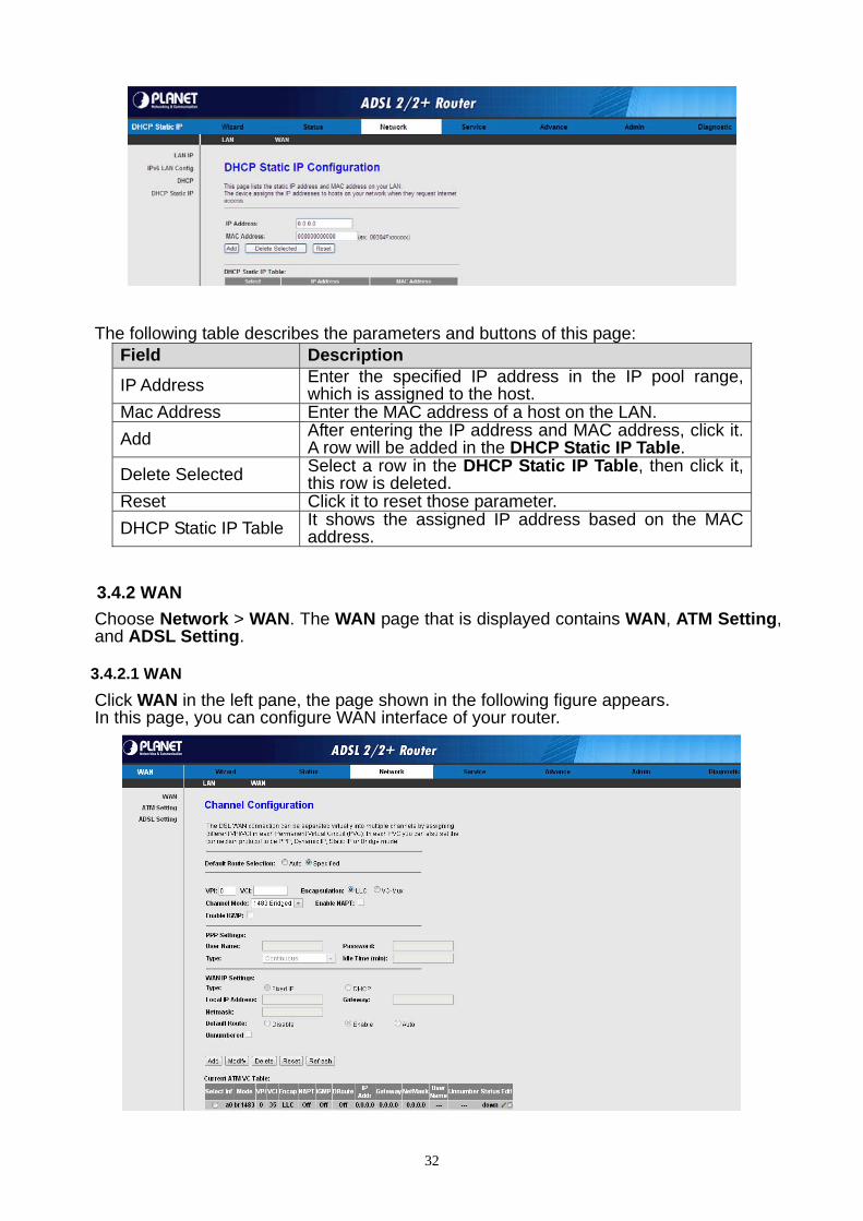
The following table describes the parameters and buttons of this page: Field Description
IP Address Enter the specified IP address in the IP pool range, which is assigned to the host.
Mac Address Enter the MAC address of a host on the LAN.
Add After entering the IP address and MAC address, click it. A row will be added in the DHCP Static IP Table.
Delete Selected Select a row in the DHCP Static IP Table, then click it, this row is deleted.
Reset Click it to reset those parameter.
DHCP Static IP Table It shows the assigned IP address based on the MAC address.
3.4.2 WAN
Choose Network > WAN. The WAN page that is displayed contains WAN, ATM Setting, and ADSL Setting.
3.4.2.1 WAN
Click WAN in the left pane, the page shown in the following figure appears. In this page, you can configure WAN interface of your router.
32
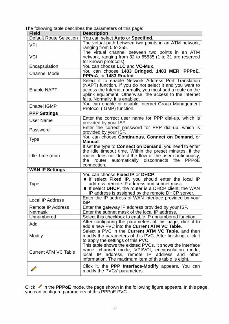
The following table describes the parameters of this page:
Field Description Default Route Selection You can select Auto or Specified.
VPI The virtual path between two points in an ATM network, ranging from 0 to 255.
VCI The virtual channel between two points in an ATM network, ranging from 32 to 65535 (1 to 31 are reserved for known protocols)
Encapsulation You can choose LLC and VC-Mux.
Channel Mode You can choose 1483 Bridged, 1483 MER, PPPoE, PPPoA, or 1483 Routed.
Enable NAPT
Select it to enable Network Address Port Translation (NAPT) function. If you do not select it and you want to access the Internet normally, you must add a route on the uplink equipment. Otherwise, the access to the Internet fails. Normally, it is enabled.
Enabel IGMP You can enable or disable Internet Group Management Protocol (IGMP) function.
PPP Settings
User Name Enter the correct user name for PPP dial-up, which is provided by your ISP.
Password Enter the correct password for PPP dial-up, which is provided by your ISP.
Type You can choose Continuous, Connect on Demand, or Manual.
Idle Time (min)
If set the type to Connect on Demand, you need to enter the idle timeout time. Within the preset minutes, if the router does not detect the flow of the user continuously, the router automatically disconnects the PPPoE connection.
WAN IP Settings
Type
You can choose Fixed IP or DHCP. If select Fixed IP, you should enter the local IP
address, remote IP address and subnet mask. If select DHCP, the router is a DHCP client, the WAN
IP address is assigned by the remote DHCP server.
Local IP Address Enter the IP address of WAN interface provided by your ISP.
Remote IP Address Enter the gateway IP address provided by your ISP. Netmask Enter the subnet mask of the local IP address. Unnumbered Select this checkbox to enable IP unnumbered function.
Add After configuring the parameters of this page, click it to add a new PVC into the Current ATM VC Table.
Modify Select a PVC in the Current ATM VC Table, and then modify the parameters of this PVC. After finishing, click it to apply the settings of this PVC.
Current ATM VC Table
This table shows the existed PVCs. It shows the interface name, channel mode, VPI/VCI, encapsulation mode, local IP address, remote IP address and other information. The maximum item of this table is eight.
Click it, the PPP Interface-Modify appears. You can modify the PVCs’ parameters.
Click in the PPPoE mode, the page shown in the following figure appears. In this page, you can configure parameters of this PPPoE PVC.
33

The following table describes the parameters and buttons of this page: Field Description
Protocol It displays the protocol type used for this WAN connection.
ATM VCC The ATM virtual circuit connection assigned for this PPP interface (VPI/VCI).
Login Name The user name provided by your ISP. Password The password provided by your ISP. Authentication Method You can choose AUTO, CHAP, or PAP.
Connection Type You can choose Continuous, Connect on Demand, or Manual.
Idle Time (s)
If choose Connect on Demand, you need to enter the idle timeout time. Within the preset minutes, if the router does not detect the flow of the user continuously, the router automatically disconnects the PPPoE connection.
Bridge You can select Bridged Ethernet, Bridged PPPoE, or Disable Bridge.
AC-Name The accessed equipment type. Service-Name The service name.
802.1q You can select Disable or Enable. After enable it, you need to enter the VLAN ID. The value ranges from 0 to 4095.
Apply Changes Click it to save the settings of this page temporarily. Return Click it to return to the Channel Configuration page. Undo Click it to refresh this page.
3.4.2.2 ATM Setting
Click ATM Setting in the left pane, the page shown in the following figure appears. In this page, you can configure the parameters of the ATM, including QoS, PCR, CDVT, SCR, and MBS.
34

The following table describes the parameters of this page: Field Description VPI The virtual path identifier of the ATM PVC. VCI The virtual channel identifier of the ATM PVC.
QoS The QoS category of the PVC. You can choose UBR, CBR, rt-VBR, or nrt-VBR.
PCR Peak cell rate (PCR) is the maximum rate at which cells can be transmitted along a connection in the ATM network. Its value ranges from 1 to 65535.
CDVT Cell delay variation tolerance (CDVT) is the amount of delay permitted between ATM cells (in microseconds). Its value ranges from 0 to 4294967295.
SCR Subtain cell rate (SCR) is the maximum rate that traffic can pass over a PVC without the risk of cell loss. Its value ranges from 0 to 65535.
MBS Maximum burst size (MBS) is the maximum number of cells that can be transmitted at the PCR. Its value ranges from 0 to 65535.
3.4.2.3 ADSL Setting
Click ADSL Setting in the left pane, the page shown in the following figure appears. In this page, you can select the DSL modulation. Mostly, you need to remain this factory default settings. The router supports these modulations: G.Lite, G.Dmt, T1.413, ADSL2, ADSL2+, AnnexL, and AnnexM. The router negotiates the modulation modes with the DSLAM.
35
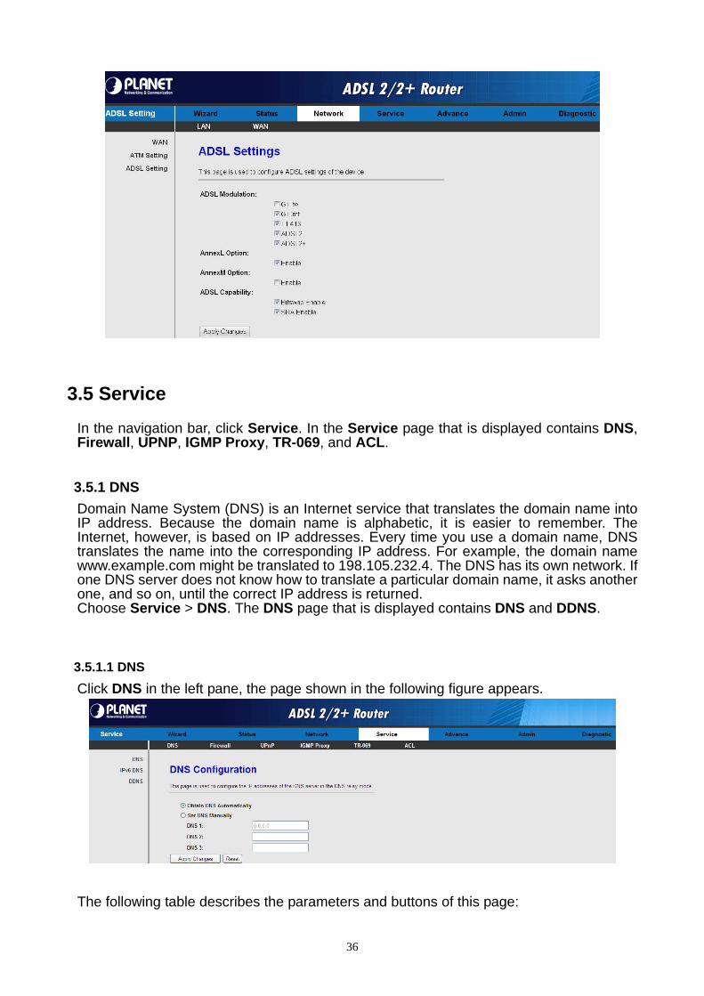
3.5 Service
In the navigation bar, click Service. In the Service page that is displayed contains DNS, Firewall, UPNP, IGMP Proxy, TR-069, and ACL.
3.5.1 DNS
Domain Name System (DNS) is an Internet service that translates the domain name into IP address. Because the domain name is alphabetic, it is easier to remember. The Internet, however, is based on IP addresses. Every time you use a domain name, DNS translates the name into the corresponding IP address. For example, the domain name www.example.com might be translated to 198.105.232.4. The DNS has its own network. If one DNS server does not know how to translate a particular domain name, it asks another one, and so on, until the correct IP address is returned. Choose Service > DNS. The DNS page that is displayed contains DNS and DDNS.
3.5.1.1 DNS
Click DNS in the left pane, the page shown in the following figure appears.
The following table describes the parameters and buttons of this page:
36
Field Description
Attain DNS Automatically Select it, the router accepts the first received DNS assignment from one of the PPPoA, PPPoE or MER enabled PVC(s) during the connection establishment.
Set DNS Manually Select it, enter the IP addresses of the primary and secondary DNS server.
Apply Changes Click it to save the settings of this page.
Reset Selected Click it to start configuring the parameters in this page.
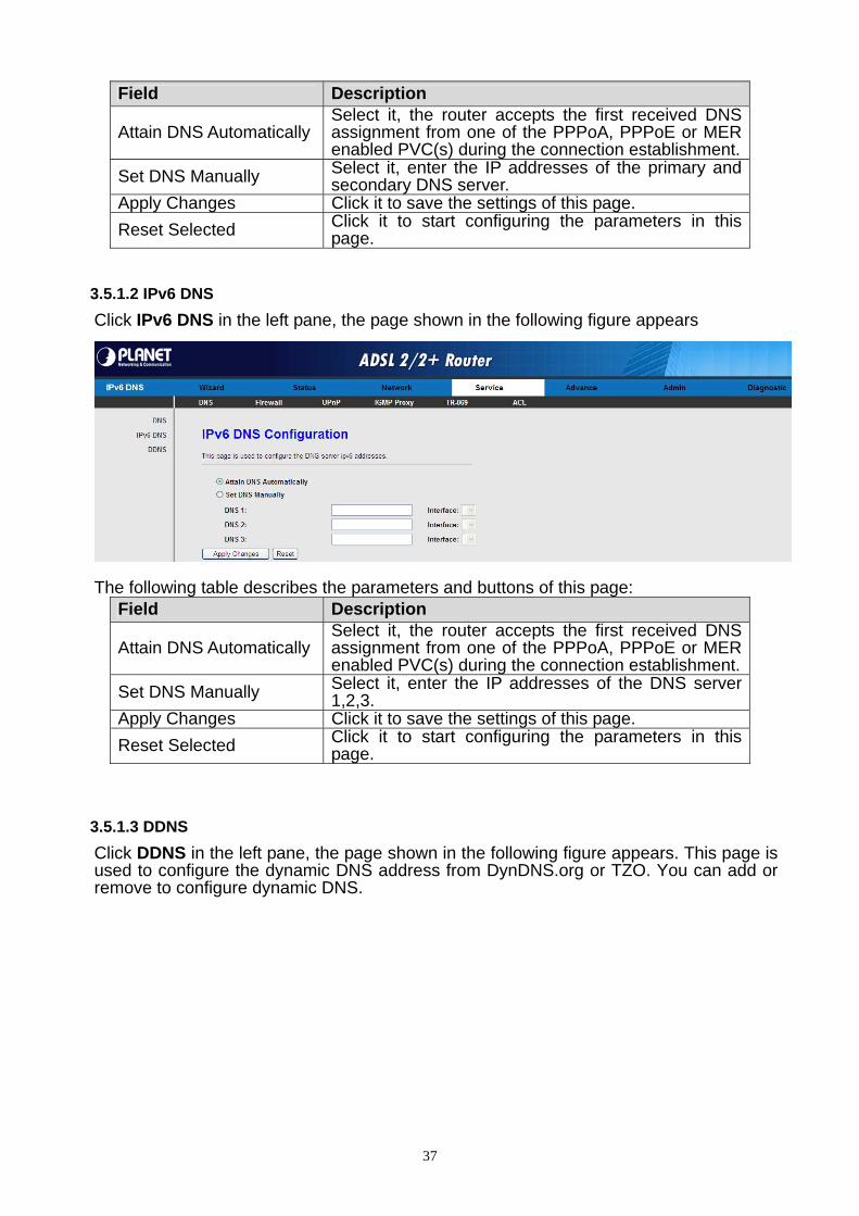
3.5.1.2 IPv6 DNS
Click IPv6 DNS in the left pane, the page shown in the following figure appears
The following table describes the parameters and buttons of this page:
Field Description
Attain DNS Automatically Select it, the router accepts the first received DNS assignment from one of the PPPoA, PPPoE or MER enabled PVC(s) during the connection establishment.
Set DNS Manually Select it, enter the IP addresses of the DNS server 1,2,3.
Apply Changes Click it to save the settings of this page.
Reset Selected Click it to start configuring the parameters in this page.
3.5.1.3 DDNS
Click DDNS in the left pane, the page shown in the following figure appears. This page is used to configure the dynamic DNS address from DynDNS.org or TZO. You can add or remove to configure dynamic DNS.
37
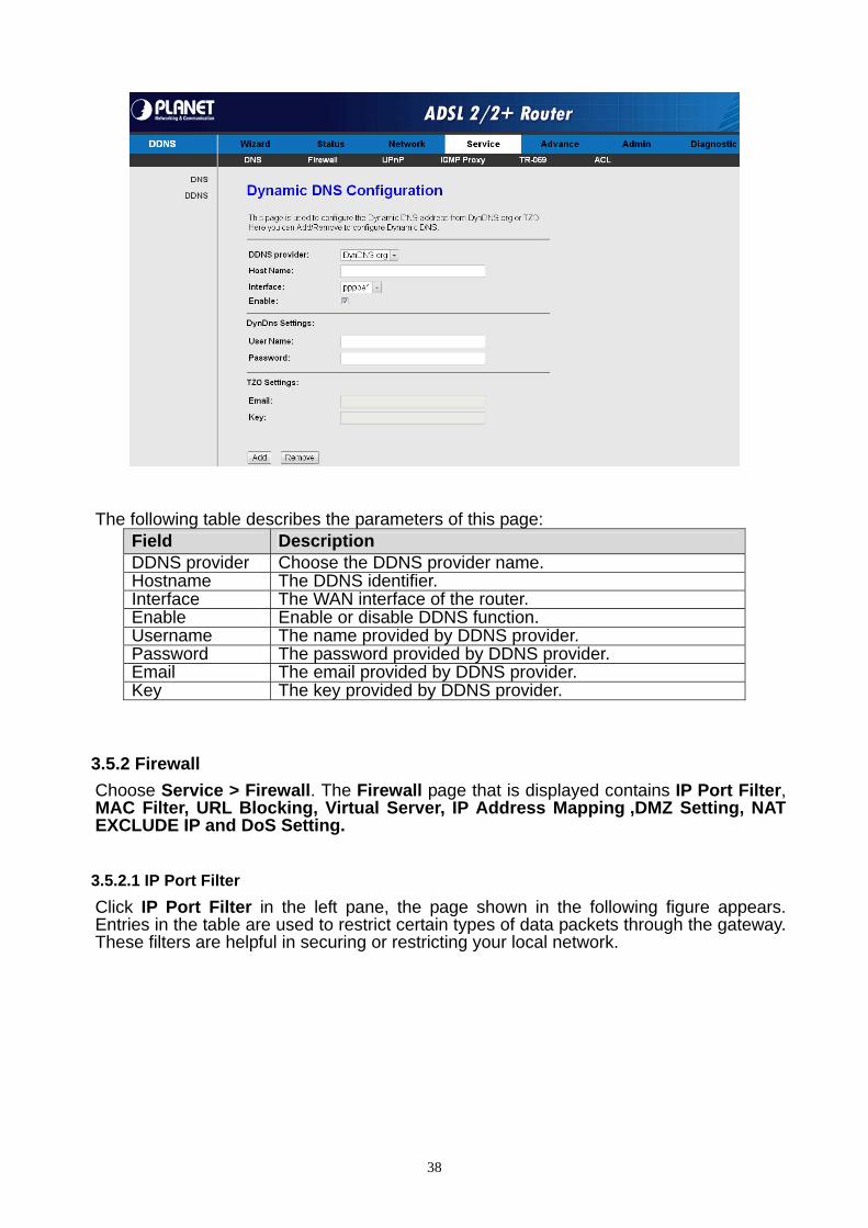
The following table describes the parameters of this page: Field Description DDNS provider Choose the DDNS provider name. Hostname The DDNS identifier. Interface The WAN interface of the router. Enable Enable or disable DDNS function. Username The name provided by DDNS provider. Password The password provided by DDNS provider. Email The email provided by DDNS provider. Key The key provided by DDNS provider.
3.5.2 Firewall
Choose Service > Firewall. The Firewall page that is displayed contains IP Port Filter, MAC Filter, URL Blocking, Virtual Server, IP Address Mapping ,DMZ Setting, NAT EXCLUDE IP and DoS Setting.
3.5.2.1 IP Port Filter
Click IP Port Filter in the left pane, the page shown in the following figure appears. Entries in the table are used to restrict certain types of data packets through the gateway. These filters are helpful in securing or restricting your local network.
38

3.5.2.2 MAC Filter
Click MAC Filter in the left pane, the page shown in the following figure appears. Entries in the table are used to restrict certain types of data packets from your local network to Internet through the gateway. These filters are helpful in securing or restricting your local network.
3.5.2.3 URL Blocking
Click URL Blocking in the left pane, the page shown in the following figure appears. This page is used to block a fully qualified domain name, such as tw.yahoo.com and filtered keyword. You can add or delete FQDN and filtered keyword.
39
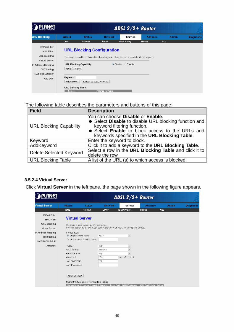
The following table describes the parameters and buttons of this page: Field Description
URL Blocking Capability
You can choose Disable or Enable. Select Disable to disable URL blocking function and
keyword filtering function. Select Enable to block access to the URLs and
keywords specified in the URL Blocking Table. Keyword Enter the keyword to block. AddKeyword Click it to add a keyword to the URL Blocking Table.
Delete Selected Keyword Select a row in the URL Blocking Table and click it to delete the row.
URL Blocking Table A list of the URL (s) to which access is blocked.
3.5.2.4 Virtual Server
Click Virtual Server in the left pane, the page shown in the following figure appears.
40
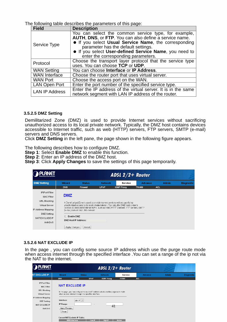
The following table describes the parameters of this page: Field Description
Service Type
You can select the common service type, for example, AUTH, DNS, or FTP. You can also define a service name. If you select Usual Service Name, the corresponding
parameter has the default settings. If you select User-defined Service Name, you need to
enter the corresponding parameters.
Protocol Choose the transport layer protocol that the service type uses. You can choose TCP or UDP.
WAN Setting You can choose Interface or IP Address. WAN Interface Choose the router port that uses virtual server. WAN Port Choose the access port on the WAN. LAN Open Port Enter the port number of the specified service type.
LAN IP Address Enter the IP address of the virtual server. It is in the same network segment with LAN IP address of the router.
3.5.2.5 DMZ Setting
Demilitarized Zone (DMZ) is used to provide Internet services without sacrificing unauthorized access to its local private network. Typically, the DMZ host contains devices accessible to Internet traffic, such as web (HTTP) servers, FTP servers, SMTP (e-mail) servers and DNS servers. Click DMZ Setting in the left pane, the page shown in the following figure appears. The following describes how to configure DMZ. Step 1 : Select Enable DMZ to enable this function. Step 2 : Enter an IP address of the DMZ host. Step 3 : Click Apply Changes to save the settings of this page temporarily.
3.5.2.6 NAT EXCLUDE IP
In the page , you can config some source IP address which use the purge route mode when access internet through the specified interface .You can set a range of the ip not via the NAT to the internet.
41
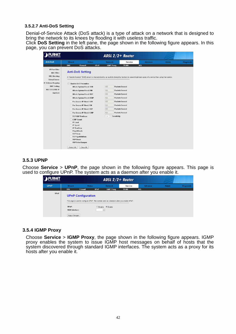
3.5.2.7 Anti-DoS Setting
Denial-of-Service Attack (DoS attack) is a type of attack on a network that is designed to bring the network to its knees by flooding it with useless traffic. Click DoS Setting in the left pane, the page shown in the following figure appears. In this page, you can prevent DoS attacks.
3.5.3 UPNP
Choose Service > UPnP, the page shown in the following figure appears. This page is used to configure UPnP. The system acts as a daemon after you enable it.
3.5.4 IGMP Proxy
Choose Service > IGMP Proxy, the page shown in the following figure appears. IGMP proxy enables the system to issue IGMP host messages on behalf of hosts that the system discovered through standard IGMP interfaces. The system acts as a proxy for its hosts after you enable it.
42
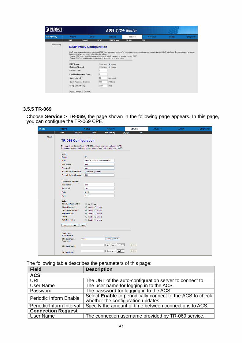
3.5.5 TR-069
Choose Service > TR-069, the page shown in the following page appears. In this page, you can configure the TR-069 CPE.
The following table describes the parameters of this page:
Field Description ACS URL The URL of the auto-configuration server to connect to. User Name The user name for logging in to the ACS. Password The password for logging in to the ACS.
Periodic Inform Enable Select Enable to periodically connect to the ACS to check whether the configuration updates.
Periodic Inform Interval Specify the amount of time between connections to ACS. Connection Request User Name The connection username provided by TR-069 service.
43

Field Description Password The connection password provided by TR-069 service. Debug
Show Message Select Enable to display ACS SOAP messages on the serial console.
CPE sends GetRPC Select Enable, the router contacts the ACS to obtain configuration updates.
Skip MReboot Specify whether to send an MReboot event code in the inform message.
Delay Specify whether to start the TR-069 program after a short delay.
Auto-Execution Specify whether to automatically start the TR-069 after the router is powered on.
3.5.6 ACL
Choose Service > ACL, the page shown in the following figure appears. In this page, you can permit the data packets from LAN or WAN to access the router. You can configure the IP address for Access Control List (ACL). If ACL is enabled, only the effective IP address in the ACL can access the router.
Note: If you select Enable in ACL capability, ensure that your host IP address is in ACL list before it takes effect.
The following table describes the parameters and buttons of this page: Field Description
Direction Select Select the router interface. You can select LAN or WAN. In this example, LAN is selected.
LAN ACL Switch Select it to enable or disable ACL function.
IP Address Enter the IP address of the specified interface. Only the IP address that is in the same network segment with the IP address of the specified interface can access the router.
Services Allowed You can choose the following services from LAN: web, telnet, ftp, tftp, snmp, or ping. You can also choose all the services.
Add After setting the parameters, click it to add an entry to the Current ACL Table.
Reset Click it to refresh this page.
44
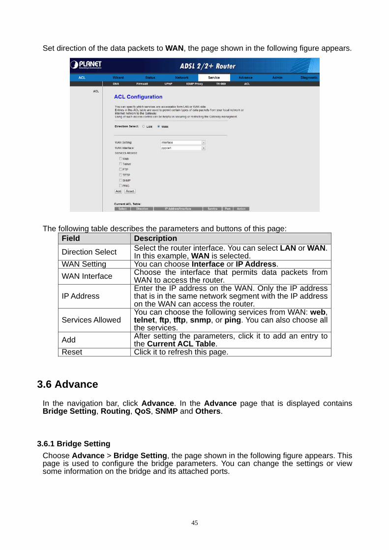
Set direction of the data packets to WAN, the page shown in the following figure appears.
The following table describes the parameters and buttons of this page:
Field Description
Direction Select Select the router interface. You can select LAN or WAN. In this example, WAN is selected.
WAN Setting You can choose Interface or IP Address.
WAN Interface Choose the interface that permits data packets from WAN to access the router.
IP Address Enter the IP address on the WAN. Only the IP address that is in the same network segment with the IP address on the WAN can access the router.
Services Allowed You can choose the following services from WAN: web, telnet, ftp, tftp, snmp, or ping. You can also choose all the services.
Add After setting the parameters, click it to add an entry to the Current ACL Table.
Reset Click it to refresh this page.
3.6 Advance
In the navigation bar, click Advance. In the Advance page that is displayed contains Bridge Setting, Routing, QoS, SNMP and Others.
3.6.1 Bridge Setting
Choose Advance > Bridge Setting, the page shown in the following figure appears. This page is used to configure the bridge parameters. You can change the settings or view some information on the bridge and its attached ports.
45

The following table describes the parameters and button of this page: Field Description
Aging Time If the host is idle for 300 seconds (default value), its entry is deleted from the bridge table.
802.1d Spanning Tree
You can select Disabled or Enabled. Select Enabled to provide path redundancy while preventing undesirable loops in your network.
Show MACs Click it to show a list of the learned MAC addresses for the bridge.
Click Show MACs, the page shown in the following figure appears. This table shows a list of learned MAC addresses for this bridge.
3.6.2 Routing
Choose Advance > Routing, the page shown in the following figure appears. The page that is displayed contains RIP and Static Route.
3.6.2.1 Static Route
Click Static Route in the left pane, the page shown in the following figure appears. This page is used to configure the routing information. You can add or delete IP routes.
46
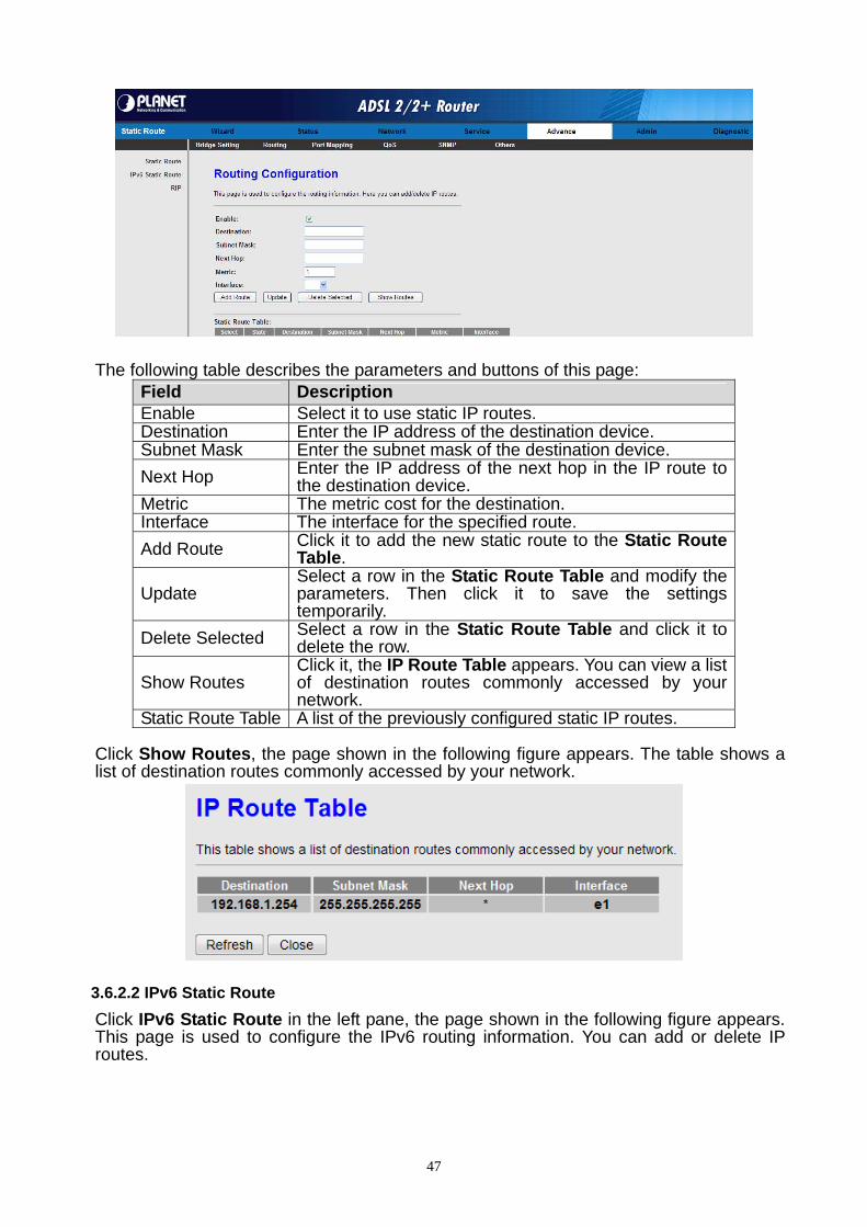
The following table describes the parameters and buttons of this page: Field Description Enable Select it to use static IP routes. Destination Enter the IP address of the destination device. Subnet Mask Enter the subnet mask of the destination device.
Next Hop Enter the IP address of the next hop in the IP route to the destination device.
Metric The metric cost for the destination. Interface The interface for the specified route.
Add Route Click it to add the new static route to the Static Route Table.
Update Select a row in the Static Route Table and modify the parameters. Then click it to save the settings temporarily.
Delete Selected Select a row in the Static Route Table and click it to delete the row.
Show Routes Click it, the IP Route Table appears. You can view a list of destination routes commonly accessed by your network.
Static Route Table A list of the previously configured static IP routes. Click Show Routes, the page shown in the following figure appears. The table shows a list of destination routes commonly accessed by your network.
3.6.2.2 IPv6 Static Route
Click IPv6 Static Route in the left pane, the page shown in the following figure appears. This page is used to configure the IPv6 routing information. You can add or delete IP routes.
47
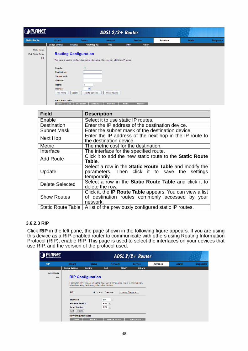
Field Description Enable Select it to use static IP routes. Destination Enter the IP address of the destination device. Subnet Mask Enter the subnet mask of the destination device.
Next Hop Enter the IP address of the next hop in the IP route to the destination device.
Metric The metric cost for the destination. Interface The interface for the specified route.
Add Route Click it to add the new static route to the Static Route Table.
Update Select a row in the Static Route Table and modify the parameters. Then click it to save the settings temporarily.
Delete Selected Select a row in the Static Route Table and click it to delete the row.
Show Routes Click it, the IP Route Table appears. You can view a list of destination routes commonly accessed by your network.
Static Route Table A list of the previously configured static IP routes.
3.6.2.3 RIP
Click RIP in the left pane, the page shown in the following figure appears. If you are using this device as a RIP-enabled router to communicate with others using Routing Information Protocol (RIP), enable RIP. This page is used to select the interfaces on your devices that use RIP, and the version of the protocol used.
48
The following table describes the parameters and buttons of this page: Field Description
RIP Select Enable, the router communicates with other RIP-enabled devices.
Apply Change Click it to save the settings of this page. Interface Choose the router interface that uses RIP.
Receive Version
Choose the interface version that receives RIP messages. You can choose RIP1, RIP2, or Both. Choose RIP1 indicates the router receives RIP v1
messages. Choose RIP2 indicates the router receives RIP v2
messages. Choose Both indicates the router receives RIP v1 and RIP
v2 messages.
Send Version
The working mode for sending RIP messages. You can choose RIP1 or RIP2. Choose RIP1 indicates the router broadcasts RIP1
messages only. Choose RIP2 indicates the router multicasts RIP2
messages only. Add Click it to add the RIP interface to the Rip Config List.
Delete Select a row in the Rip Config List and click it to delete the row.
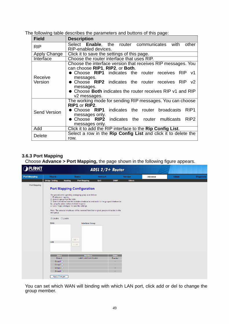
3.6.3 Port Mapping Choose Advance > Port Mapping, the page shown in the following figure appears. You can set which WAN will binding with which LAN port, click add or del to change the group member.
49

3.6.4 QoS
Choose Advance > QoS, the page shown in the following figure appears. Entries in the QoS Rule List are used to assign the precedence for each incoming packet based on physical LAN port, TCP/UDP port number, source IP address, destination IP address and other information.
Step 1 : Enable IP QoS and click Apply to enable IP QoS function. Step 2 : Click add rule to add a new IP QoS rule. The page shown in the following figure appears.
The following table describes the parameters and buttons of this page: Field Description
IP QoS Select to enable or disable IP QoS function. You need to enable IP QoS if you want to configure the parameters of this page.
QoS Policy You can choose stream based, 802.1p based, or DSCP based.
50

Field Description Schedule Mode You can choose strict prior or WFQ (4:3:2:1). Source IP The IP address of the source data packet. Source Mask The subnet mask of the source IP address. Destination IP The IP address of the destination data packet. Destination Mask The subnet mask of the destination IP address. Source Port The port of the source data packet. Destination Port The port of the destination data packet.
Protocol The protocol responds to the IP QoS rules. You can choose TCP, UDP, or ICMP.
Physical Port The LAN interface responds to the IP QoS rules.
Set priority The priority of the IP QoS rules. P0 is the highest priority and P3 is the lowest.
IP Precedence You can choose from 0 to 7 define the priority in the ToS of the IP data packet.
IP ToS The type of IP ToS for classifying the data package You can choose Normal Service, Minimize Cost, Maximize Reliability, Maximize Throughput, or Minimize Delay.
802.1p You can choose from 0 to 7. delete Select a row in the QoS rule list and click it to delete the row. delete all Select all the rows in the QoS rule list and click it to delete the rows.
3.6.5 SNMP
Choose Advance > SNMP, the page shown in the following figure appears. You can configure the SNMP parameters.
The following table describes the parameters of this page: Field Description
Enable SNMP Select it to enable SNMP function. You need to enable SNMP, and then you can configure the parameters of this page.
Trap IP Address Enter the trap IP address. The trap information is sent to the corresponding host.
Community name (read-only)
The network administrators must use this password to read the information of this router.
Community name (write-only)
The network administrators must use this password to configure the information of the router.
51
3.6.6 Others
Choose Advance > Others, the page shown in the following figure appears.
3.7 Admin
In the navigation bar, click Admin. The Admin page that is displayed contains Commit/Reboot, Upgrade, System Log, Password and Time Zone.
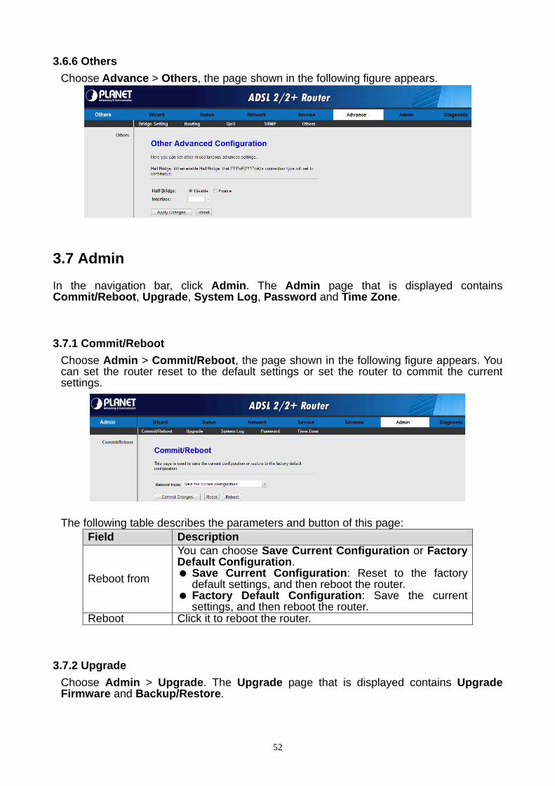
3.7.1 Commit/Reboot
Choose Admin > Commit/Reboot, the page shown in the following figure appears. You can set the router reset to the default settings or set the router to commit the current settings.
The following table describes the parameters and button of this page: Field Description
Reboot from
You can choose Save Current Configuration or Factory Default Configuration. Save Current Configuration: Reset to the factory
default settings, and then reboot the router. Factory Default Configuration: Save the current
settings, and then reboot the router. Reboot Click it to reboot the router.
3.7.2 Upgrade
Choose Admin > Upgrade. The Upgrade page that is displayed contains Upgrade Firmware and Backup/Restore.
52

Caution: Do not turn off the router or press the Reset button while the procedure is in progress.
3.7.2.1 Upgrade Firmware
Click Upgrade Firmware in the left pane, the page shown in the following figure appears. In this page, you can upgrade the firmware of the router.
The following table describes the parameters and button of this page: Field Description Select File Click Browse to select the firmware file.
Upload After selecting the firmware file, click Upload to starting upgrading the firmware file.
Reset Click it to starting selecting the firmware file.
3.7.2.2 Backup/Restore
Click Backup/Restore in the left pane, the page shown in the following figure appears. You can backup the current settings to a file and restore the settings from the file that was saved previously.
The following table describes the parameters and button of this page:
Field Description
Save Settings to File Click it, and select the path. Then you can save the configuration file of the router.
Load Settings from File Click Browse to select the configuration file.
Upload After selecting the configuration file of the router, click Upload to start uploading the configuration file of the router.
53

3.7.3 System Log
Choose Admin > System Log, the page shown in the following figure appears. In this page, you can enable or disable system log function and view the system log.
3.7.4 Password
Choose Admin > Password, the page shown in the following figure appears. By default, the user name and password are admin and admin respectively. The common user name and password are user and user respectively.
The following table describes the parameters of this page: Field Description User Name You can create your account at this item.
Privilege Choose the access permission, you can choose User and root
Old Password If you want to change the password, select the account and enter the old password.
New Password Enter the password to which you want to change the old password.
Confirmed Password Enter the new password again. User Account Table Select it, and you can change the above parameter.
54

3.7.5 Time Zone
Choose Admin > Time Zone, the page shown in the following figure appears. You can configure the system time manually or get the system time from the time server.
The following table describes the parameters of this page: Field Description System Time Set the system time manually. NTP Configuration
State Select enable or disable NTP function. You need to enable NTP if you want to configure the parameters of NTP.
Server Set the primary NTP server manually. Server2 Set the secondary NTP server manually.
Time Zone Choose the time zone in which area you are from the drop down list.
3.8 Diagnostic
In the navigation bar, click Diagnostic. The Diagnostic page that is displayed contains Ping, ATM Loopback, ADSL and Diagnostic Test.
3.8.1 Ping
Choose Diagnostic > Ping. The page shown in the following figure appears.
The following table describes the parameter and button of this page: Field Description Host Enter the valid IP address or domain name. Run Ping Click it to start to Ping.
55

3.8.2 Ping6
Choose Diagnostic > Ping6. The page shown in the following figure appears. The following table describes the parameter and button of this page:
Field Description
Target Address Enter the valid IP address or domain name.
Interface Select the interface on this item.
Run Ping Click it to start to Ping.
3.8.3 ATM Loopback
Choose Diagnostic > ATM Loopback. The page shown in the following figure appears. In this page, you can use VCC loopback function to check the connectivity of the VCC. The ATM loopback test is useful for troubleshooting problems with the DSLAM and ATM network.
Click Run Lookback to start testing.
3.8.4 ADSL
Choose Diagnostic > ADSL. The page shown in the following figure appears. It is used for ADSL tone diagnostics.
56

Click Start to start ADSL tone diagnostics.
3.8.5 Diagnostic Test
Choose Diagnostic > Diagnostic Test, the page shown in the following figure appears. In this page, you can test the DSL connection. You can also view the LAN status connection and ADSL connection.
Click Run Diagnostic Test to start testing.
57

Appendix A: Glossary Address mask
A bit mask select bits from an Internet address for subnet addressing. The mask is 32 bits
long and selects the network portion of the Internet address
and one or more bits of the local portion. Sometimes it called subnet mask.
AAL5
ATM Adaptation Layer - This layer maps higher layer user data into ATM cells, making the
data suitable for transport through the ATM network.
ADSL
Asymmetric digital subscriber line
ATM
Asynchronous Transfer Mode - A cell-based data transfer technique in which channel
demand determines packet allocation. ATM offers fast packet technology,
real time, and demand led switching for efficient use of network resources.
AWG
American Wire Gauge - The measurement of thickness of a wire
Bridge
A device connects two or more physical networks and forward packets between them.
Bridges can usually be made to filter packets, that is, to forward only certain traffic. Related
devices are repeaters which simply forward electrical signals from one cable to the other
and full-fledged routers which make routing decisions based on several criteria.
Broadband
Characteristic of any network multiplexes independent network carriers onto a single cable.
Broadband technology allows several networks to coexist on one single cable; traffic from
one network does not interfere with traffic from another. Broadcast a packet delivery system
where a copy of a given packet is given to all hosts attached to the network. Example:
Ethernet.
CO
Central Office. Refers to equipment located at a Telco or service provider's office.
CPE
Customer Premises Equipment located in a user's premises
58
59
DHCP (Dynamic Host Configuration Protocol)
DHCP is software that automatically assigns IP addresses to client stations logging onto a
TCP/IP network. DHCP eliminates having to manually assign permanent IP addresses to
every device on your network. DHCP software typically runs in servers and is also found in
network devices such as Routers.
DMT
Discrete Multi-Tone frequency signal modulation
Downstream rate
The line rate for return messages or data transfers from the network machine to the user's
premises machine.
DSLAM
Digital Subscriber Line Access Multiplex
Dynamic IP Addresses
A dynamic IP address is an IP address that is automatically assigned to a client station
(computer, printer, etc.) in a TCP/IP network. Dynamic IP addresses are typically assigned
by a DHCP server, which can be a computer on the network or another piece of hardware,
such as the Router. A dynamic IP address
may change every time your computer connects to the network.
Encapsulation
The technique layer protocols in which a layer adds header information to the protocol data
unit (PDU) from the layer above. As an example, in Internet terminology, a packet would
contain a header from the physical layer, followed by a header from the network layer (IP),
followed by a header from the transport
layer (TCP), and followed by the application protocol data.
Ethernet
One of the most common local area network (LAN) wiring schemes, Ethernet has a
transmission rate of 10 Mbps.
FTP
File Transfer Protocol. The Internet protocol (and program) transfer files between hosts.
Hop count
A measure of distance between two points on the Internet. It is equivalent to the number of
gateways that separate the source and destination.
HTML
Hypertext Markup Language - The page-coding language for the World Wide Web.
HTML browser
A browser used to traverse the Internet, such as Netscape or Microsoft Internet Explorer.
http
Hypertext Transfer Protocol - The protocol carry world-wide-web (www) traffic between a
www browser computer and the www server being accessed.
ICMP
Internet Control Message Protocol - The protocol handle errors and control messages at
the IP layer. ICMP is actually part of the IP protocol.
Internet address
An IP address is assigned in blocks of numbers to user organizations accessing the
Internet. These addresses are established by the United States Department
of Defense's Network Information Center. Duplicate addresses can cause major problems
on the network, but the NIC trusts organizations to use individual
addresses responsibly. Each address is a 32-bit address in the form of x.x.x.x where x is an
eight- bit number from 0 to 255. There are three classes: A, B and C, depending on how
many computers on the site are likely to be connected.
Internet Protocol (IP)
The network layer protocol for the Internet protocol suite
IP address
The 32-bit address assigned to hosts that want to participate in a TCP/IP Internet.
ISP
Internet service provider - A company allows home and corporate users to connect to the
Internet.
MAC
Media Access Control Layer - A sub-layer of the Data Link Layer (Layer 2) of the ISO OSI
Model responsible for media control.
60

MIB
Management Information Base - A collection of objects can be accessed via a network
management protocol, such as SNMP and CMIP (Common Management Information
Protocol).
NAT
Network Address Translation - A proposal for IP address reuse, where the local IP address
is mapped to a globally unique address.
NVT
Network Virtual Terminal
PAP
Password Authentication Protocol
PORT
The abstraction used in Internet transport protocols to distinguish among multiple
simultaneous connections to a single destination host.
POTS
Plain Old Telephone Service - This is the term describe basic telephone service.
PPP
Point-to-Point-Protocol - The successor to SLIP, PPP provides router-to-router and
host-to-network connections over both synchronous and asynchronous circuits.
PPPoE
PPP over Ethernet is a protocol for connecting remote hosts to the Internet over an
always-on connection by simulating a dial-up connection.
Remote server
A network computer allows a user to log on to the network from a distant location.
RFC
Request for Comments - Refers to documents published by the Internet Engineering Task
Force (IETF) proposing standard protocols and procedures for the Internet. RFC can be
found at www.ietf.org.
61
Route
The path that network traffic takes from its source to its destination. The route a datagram
may follow can include many gateways and many physical networks.
In the Internet, each datagram is routed separately.
Router
A system is responsible for making decisions about which of several paths network (or
Internet) traffic will follow. To do this, it uses a routing protocol to gain information about the
network and algorithms to choose the best route based on several criteria known as
"routing metrics".
Routing Table
Information stored within a router that contains network path and status information. It is
used to select the most appropriate route to forward information along.
Routing Information Protocol
Routers periodically exchange information with one another so that they can determine
minimum distance paths between sources and destinations.
SNMP
Simple Network Management Protocol - The network management protocol of choice for
TCP/IP-based Internet.
SOCKET
(1) The Berkeley UNIX mechanism for creating a virtual connection between processes.
(2) IBM term for software interfaces that allow two UNIX application programs to talk via
TCP/IP protocols.
Spanning-Tree Bridge Protocol (STP)
Spanning-Tree Bridge Protocol (STP) - Part of an IEEE standard. A mechanism for
detecting and preventing loops from occurring in a multi-bridged environment.
When three or more LAN's segments are connected via bridges, a loop can occur. Because
of a bridge forwards all packets that are not recognized as being local,
some packets can circulate for long periods of time, eventually degrading system
performance. This algorithm ensures only one path connects any pair of stations, selecting
one bridge as the 'root' bridge, with the highest priority one as identifier, from which all
paths should radiate.
62
Spoofing
A method of fooling network end stations into believing that keep alive signals have come
from and returned to the host. Polls are received and returned locally at
either end
Static IP Address
A static IP address is an IP address permanently assigned to computer in a TCP/IP network.
Static IP addresses are usually assigned to networked devices that are consistently
accessed by multiple users, such as Server PCs, or printers. If you are using your Router to
share your cable or DSL Internet connection, contact your ISP to see if they have assigned
your home a static IP address. You will need that address during your Router's
configuration.
Subnet
For routing purposes, IP networks can be divided into logical subnets by using a subnet
mask. Values below those of the mask are valid addresses on the subnet.
TCP
Transmission Control Protocol - The major transport protocol in the Internet suite of
protocols provides reliable, connection-oriented full-duplex streams.
TFTP
Trivial File Transfer Protocol. A simple file transfer protocol (a simplified version of FTP)
that is often boot diskless workstations and other network devices such as routers over a
network (typically a LAN).
Telnet
The virtual terminal protocol in the Internet suite of protocols - Allows users of one host to
log into a remote host and act as normal terminal users of that host.
Transparent bridging
The intelligence necessary to make relaying decisions exists in the bridge itself and is thus
transparent to the communicating workstations. It involves frame forwarding, learning
workstation addresses, and ensuring no topology loops exist (in conjunction with the
Spanning-Tree algorithm).
63

64
UDP
User Datagram Protocol - A connectionless transport protocol that runs on top of TCP/IP's
IP. UDP, like TCP, uses IP for delivery; however, unlike TCP, UDP provides for exchange
of datagram without acknowledgments or guaranteed delivery. Best suited for small,
independent requests, such as requesting a MIB value from an SNMP agent, in which first
setting up a connection would take more time than sending the data.
UNI signaling
User Network Interface signaling for ATM communications.
Virtual Connection (VC)
A link that seems and behaves like a dedicated point-to-point line or a system that delivers
packets in sequence, as happens on an actual point-to-point network. In reality, the data is
delivered across a network via the most appropriate route. The sending and receiving
devices do not have to be aware of the options and the route is chosen only when a
message is sent. There is no pre-arrangement, so each virtual connection exists only for
the duration of that one transmission.
WAN
Wide area network - A data communications network that spans any distance and is usually
provided by a public carrier (such as a telephone company or service provider).
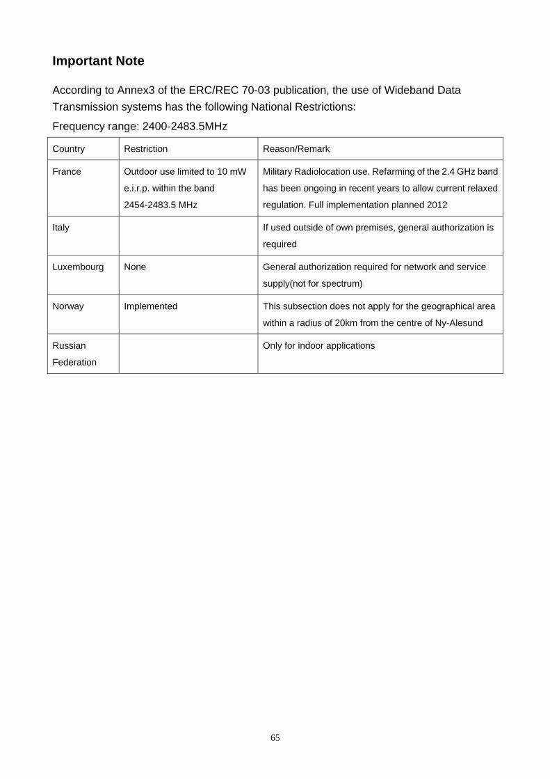
Important Note
According to Annex3 of the ERC/REC 70-03 publication, the use of Wideband Data
Transmission systems has the following National Restrictions:
Frequency range: 2400-2483.5MHz
Country Restriction Reason/Remark
France Outdoor use limited to 10 mW
e.i.r.p. within the band
2454-2483.5 MHz
Military Radiolocation use. Refarming of the 2.4 GHz band
has been ongoing in recent years to allow current relaxed
regulation. Full implementation planned 2012
Italy If used outside of own premises, general authorization is
required
Luxembourg None General authorization required for network and service
supply(not for spectrum)
Norway Implemented This subsection does not apply for the geographical area
within a radius of 20km from the centre of Ny-Alesund
Russian
Federation
Only for indoor applications
65