adr-10000_i&m manual_v7.1-7.15_253224795-a_ed.01
TRANSCRIPT
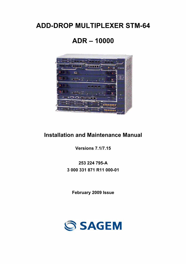
ADD-DROP MULTIPLEXER STM-64
ADR – 10000
Installation and Maintenance Manual
Versions 7.1/7.15
253 224 795-A 3 000 331 871 R11 000-01
February 2009 Issue

ADR10000 - Installation and Maintenance Manual- 253 224 795-A Sagem Communications document. Reproduction and disclosure prohibited
LIST OF CHANGES
(A new edition replaces any previous versions)
No Date Change description
Page
288 134 025-01 April 2008 Creation of original user guide All pages
253 224 795-A
3 000 331 871 R11 000-01
February 2009 Minor modifications All pages

ADR10000 - Installation and Maintenance Manual- 253 224 795-A Sagem Communications document. Reproduction and disclosure prohibited Page i
Contents
ABOUT THIS MANUAL .................................................................................................................................... XI
OVERVIEW.............................................................................................................................................XI INTENDED AUDIENCE..............................................................................................................................XI DOCUMENT ORGANIZATION ....................................................................................................................XI DOCUMENT CONVENTIONS ....................................................................................................................XII RELATED DOCUMENTATION ...................................................................................................................XII OBTAINING TECHNICAL DOCUMENTATION.............................................................................................. XIII TECHNICAL ASSISTANCE ...................................................................................................................... XIII
INTRODUCTION .................................................................................................................................. 1-1 ADR-10000 PLATFORM OVERVIEW..................................................................................................... 1-1 ADR-10000 I/O PROTECTION OPTIONS............................................................................................... 1-2
Basic ADR-10000 Shelf................................................................................................................ 1-2 Expanded ADR-10000 with I/O Protection ................................................................................... 1-4
ADR-10000 SHELF WITH ONE OCU AND TWO TPUS............................................................................ 1-6 BEFORE YOU START/SAFETY GUIDELINES .................................................................................. 2-1
OVERVIEW.......................................................................................................................................... 2-1 GENERAL SAFETY REQUIREMENTS ...................................................................................................... 2-2 GROUNDING REQUIREMENTS............................................................................................................... 2-2
Rack Grounding Requirements .................................................................................................... 2-3 Equipment Grounding Requirements ........................................................................................... 2-4
POWER SUPPLY REQUIREMENTS ......................................................................................................... 2-4 Connection via RAP ..................................................................................................................... 2-4
UL STATUTORY WARNINGS AND REQUIREMENTS ................................................................................. 2-4 Identification of TUV CE Listing.................................................................................................... 2-4 Warning Label .............................................................................................................................. 2-5 UL Overcurrent Protection Requirements .................................................................................... 2-5 UL Equipment Grounding Requirements ..................................................................................... 2-5 UL Requirements for Grounded Conductors................................................................................ 2-6
ITU-T/TELCORDIA STATUTORY WARNINGS AND REQUIREMENTS........................................................... 2-6 DC Supply Circuit Connection to the Grounding Conductor ........................................................ 2-6
LASER SAFETY REQUIREMENTS........................................................................................................... 2-7 Laser Classification ...................................................................................................................... 2-7 Warning Labels for Laser Products .............................................................................................. 2-7 Laser Safety Statutory Warning ................................................................................................... 2-7 Laser Device Operating Precautions............................................................................................ 2-8 Laser information.......................................................................................................................... 2-8
PROTECTION AGAINST ELECTROSTATIC DISCHARGE ............................................................................. 2-9 General ....................................................................................................................................... 2-10 Personnel Training ..................................................................................................................... 2-10 Use of Temporary EPA............................................................................................................... 2-11 Work Arrangements within a Temporary EPA............................................................................ 2-13

ADR10000 - Installation and Maintenance Manual- 253 224 795-A Page ii Sagem Communications document. Reproduction and disclosure prohibited
EQUIPMENT INSTALLATION............................................................................................................. 3-1 OVERVIEW.......................................................................................................................................... 3-1
Preliminary Preparations .............................................................................................................. 3-2 Equipment Installation Sequence................................................................................................. 3-2 ADR-10000 Horizontal Shelf and Accessories Installation Sequence ......................................... 3-3 ADR-10000 Vertical Shelf and Accessories Installation Sequence ............................................. 3-6
OUTLINE OF INSTALLATION PROCEDURE .............................................................................................. 3-9 UNPACKING AND PERFORMING VISUAL INSPECTION............................................................................ 3-11 SITE PREPARATION........................................................................................................................... 3-12
Environmental Requirements ..................................................................................................... 3-12 Physical Location........................................................................................................................ 3-12 Power Sources ........................................................................................................................... 3-14
TOOLS AND TEST EQUIPMENT ........................................................................................................... 3-15 Cleaning Optical Connectors...................................................................................................... 3-15
PREPARING CABLES AND FIBERS....................................................................................................... 3-15 Grounding Cables....................................................................................................................... 3-16 DC Power Cables ....................................................................................................................... 3-18
RAP input power cables ........................................................................................................................ 3-18 Shelf power cables ................................................................................................................................ 3-19
Alarm Cables .............................................................................................................................. 3-19 Management Cables .................................................................................................................. 3-20 Timing (Clock) Cables ................................................................................................................ 3-20 Electric Traffic Cables................................................................................................................. 3-20 Optical Fibers ............................................................................................................................. 3-21 Data Cables for EISMBs and DIOMs. ........................................................................................ 3-22
INSTALLATION OPTIONS..................................................................................................................... 3-23 Layout of ADR-10000 Horizontal Installation in ETSI A Racks .................................................. 3-24 Layout of ADR-10000 Vertical Installation in ETSI A Racks ...................................................... 3-28
INSTALLING ANCILLARY UNITS IN RACKS ............................................................................................ 3-29 Installing the xRAP-B/BM ........................................................................................................... 3-29
Attaching protective covers ................................................................................................................... 3-34 Installing the xRAP-B/BM circuit breakers ............................................................................................. 3-40
INSTALLING THE ADR-10000 SHELF IN RACKS................................................................................... 3-43 Environmental Considerations ................................................................................................... 3-44 Typical ADR-10000 Installation .................................................................................................. 3-45 Installing the ADR-10000 Shelf in the Horizontal Position ......................................................... 3-47 Installing the ADR-10000 Shelf in the Vertical Position ............................................................. 3-47
GROUNDING THE ADR-10000 SHELF ................................................................................................ 3-50 INSTALLING ADR-10000 CARDS........................................................................................................ 3-52
FCU300 Card ............................................................................................................................. 3-52 ECU300 Card ............................................................................................................................. 3-53 MXC300 Card............................................................................................................................. 3-54 Quad I/O Cards .......................................................................................................................... 3-57 Installing SIM64_XFP Cards in Quad I/O Slots.......................................................................... 3-58 To prepare quad I/O slots for SIM64_XFP installation............................................................... 3-58
INSTALLING ADR-10000 MODULES ................................................................................................... 3-61 Installing, Optical, and Electrical I/O Modules ............................................................................ 3-61
Installing SIM16_1 modules in quad slots ............................................................................................. 3-63 Installing SFP transceivers in optical modules ...................................................................................... 3-65
Installing Double-Slot Modules................................................................................................... 3-66 INSTALLING TPU MODULES............................................................................................................... 3-67
Installing the TC/TCF Module in the TPU Shelf ......................................................................... 3-68 Installing Single-Slot TPMs in the TPU ...................................................................................... 3-69 Installing Optical Amplifiers in the TPU ...................................................................................... 3-70 Installing Double-Slot TPMs in the TPU..................................................................................... 3-70 Installing Triple-Slot TPMs in the TPU ....................................................................................... 3-71
ADR-10000 ACCESSORIES............................................................................................................... 3-73 xRAP-B/BM................................................................................................................................. 3-73 Rack Alarm Panel Power and Alarm Connection Options ......................................................... 3-76
ADR10000 - Installation and Maintenance Manual- 253 224 795-A Sagem Communications document. Reproduction and disclosure prohibited Page iii
CONNECTING FIBERS AND CABLES IN ETSI A RACKS ......................................................................... 3-78
Connecting Power Cables .......................................................................................................... 3-79 Connecting Alarm Cables........................................................................................................... 3-79 Connecting Optical Fibers to Optical Modules and Cards ......................................................... 3-80 Routing and Connecting Electrical Interface Cables to Electrical Modules ............................... 3-81
Routing and connecting multipair cables ............................................................................................... 3-81 Installing an xDDF-21 patch panel ........................................................................................................ 3-82 Routing and connecting coaxial cables ................................................................................................. 3-82
Connecting I/O Protection Cables in the ADR-10000 ................................................................ 3-83 ADR-10000 1:1 protection scheme connections ................................................................................... 3-84 ADR-10000 1:2 protection scheme connections ................................................................................... 3-85 ADR-10000 1:3 protection scheme connections ................................................................................... 3-86
Connecting Electrical Interfaces through the TPU ..................................................................... 3-87 Routing and Connecting Cables to Data Modules (EISMBs/DIOMs)......................................... 3-90
Connecting an optical fiber to a data module ........................................................................................ 3-90 Connecting Timing (Clock) Cables............................................................................................. 3-91 Connecting Management Cables ............................................................................................... 3-92 Tool Kit........................................................................................................................................ 3-92
Extracting RJ-45 connectors ................................................................................................................. 3-93 Extracting/Inserting LC connectors and SFPs ....................................................................................... 3-96 Extracting/Inserting DIN 1.0/2.3 coaxial connectors ............................................................................ 3-103
ATTACHING TPUS/OCU TO THE ADR-10000 SHELF........................................................................ 3-107 Installing a TPU/OCU on the ADR-10000 shelf........................................................................ 3-108 Installing a TPU under the ADR-10000 Shelf........................................................................... 3-111 Adding a Second TPU/OCU..................................................................................................... 3-114
MAINTENANCE ................................................................................................................................... 4-1 OVERVIEW.......................................................................................................................................... 4-1 REQUIRED TEST EQUIPMENT, TOOLS, AND MATERIALS ......................................................................... 4-1 PREVENTIVE MAINTENANCE ................................................................................................................ 4-1
Recommended Cleaning Methods ............................................................................................... 4-3 TRAFFIC MONITORING SYSTEM............................................................................................................ 4-3
Principles of Operation ................................................................................................................. 4-3 Selecting a module.................................................................................................................................. 4-5 Selecting a channel ................................................................................................................................. 4-5 Stabilization time ..................................................................................................................................... 4-5 Response to events................................................................................................................................. 4-5 Assigning modules to slots ...................................................................................................................... 4-6 Monitoring options ................................................................................................................................... 4-6
Monitoring Signal Levels .............................................................................................................. 4-6 Monitoring Modules Traffic ........................................................................................................... 4-7
ONSITE TROUBLESHOOTING ................................................................................................................ 4-7 Troubleshooting Power Problems ................................................................................................ 4-8 Troubleshooting Using Component Indicators ............................................................................. 4-9 Troubleshooting the Timing Subsystem..................................................................................... 4-12 Troubleshooting Transmission and Traffic Alarms..................................................................... 4-12 Troubleshooting Management Communication.......................................................................... 4-13
REPLACING CARDS AND MODULES .................................................................................................... 4-14 Safety and Workmanship ........................................................................................................... 4-14 Replacing MXC300 Cards .......................................................................................................... 4-15 Replacing the NVM on MXC300 Cards...................................................................................... 4-16 Replacing ECU300/ECU300-F Cards ........................................................................................ 4-17 Replacing I/O Modules ............................................................................................................... 4-17 Replacing SFP/XFP Transceivers.............................................................................................. 4-18 Replacing the FCU300 ............................................................................................................... 4-18
REPLACING RAP COMPONENTS ........................................................................................................ 4-19 Replacing xRAP-B/BM Circuit Breakers..................................................................................... 4-19

ADR10000 - Installation and Maintenance Manual- 253 224 795-A Page iv Sagem Communications document. Reproduction and disclosure prohibited
CONNECTOR PIN ASSIGNMENTS....................................................................................................A-1 OVERVIEW..........................................................................................................................................A-1 ECU300/ECU300-F CARD CONNECTORS...........................................................................................A-1
ALARMS Connector .....................................................................................................................A-1 Alarms client cable ..................................................................................................................................A-3
F-CHANNEL Connector ...............................................................................................................A-4 T3_1/T4_1 and T3_2/T4_2 Connectors .......................................................................................A-5 ETHERNET Connectors...............................................................................................................A-6
MXC300 DC INPUT POWER CONNECTORS..........................................................................................A-7 PIM2_63/B CONNECTION DATA ..........................................................................................................A-7 EISMB/DIOM CONNECTORS ............................................................................................................A-10 XRAP-B/BM CONNECTORS ..............................................................................................................A-12
Shelf DC Input Power Connectors .............................................................................................A-12 SHELF Alarm Connectors ..........................................................................................................A-12 ALARMS Connector ...................................................................................................................A-14
RACK INSTALLATION........................................................................................................................B-1 INSTALLING EQUIPMENT RACKS...........................................................................................................B-1
Rack Floor Marking ......................................................................................................................B-1 Rack Installation on Concrete Floors ...........................................................................................B-2 Rack Installation on Wooden Floors.............................................................................................B-2 Rack Installation on Floating (Suspended) Floors .......................................................................B-4 Suspended Overhead Tray Assembly..........................................................................................B-5 Installing Extendable Rails ...........................................................................................................B-5 Rack Grounding............................................................................................................................B-5
19" RACK INSTALLATION......................................................................................................................B-6 REFERENCE DOCUMENTS ...............................................................................................................C-1

ADR10000 - Installation and Maintenance Manual- 253 224 795-A Sagem Communications document. Reproduction and disclosure prohibited Page v
List of Figures
Figure 1-1: ADR-10000 shelf......................................................................................................... 1-2 Figure 1-2: Basic ADR-10000 shelf, horizontal installation...........................................................1-3 Figure 1-3: Basic ADR-10000 shelf, vertical Installation...............................................................1-3 Figure 1-4: ADR-10000 with one TPU on top of the shelf.............................................................1-4 Figure 1-5: ADR-10000 with two TPUs .........................................................................................1-5 Figure 1-6: ADR-10000 with an OCU and two TPUs....................................................................1-6
Figure 2-1: ADR-10000 TUV CE label ..........................................................................................2-4 Figure 2-2: Power input warning label........................................................................................... 2-5 Figure 2-3: Basic ESD warning symbol.........................................................................................2-9 Figure 2-4: Typical temporary EPA arrangement........................................................................2-12
Figure 3-1: Components of ADR-10000 horizontal installation.....................................................3-3 Figure 3-2: Components of ADR-10000 vertical installation .........................................................3-6 Figure 3-3: ADR-10000 horizontal installation space dimension ................................................3-14 Figure 3-4: Typical ADR-10000 horizontal installation in an ETSI A rack..................................3-24 Figure 3-5: Typical horizontal installation of two ADR-10000 shelves in an ETSI A rack..........3-25 Figure 3-6: Typical horizontal installation of three basic ADR-10000 shelves in 2200 mm ETSI A rack .................................................................................................................................3-26 Figure 3-7: Typical horizontal installation of three ADR-10000 shelves with TPUs in 2600 mm ETSI A rack ..........................................................................................................................3-27 Figure 3-8: Typical ADR-10000 vertical installation in an ETSI A rack......................................3-28 Figure 3-9: Location of xRAP-B grounding stud..........................................................................3-31 Figure 3-10: Location of xRAP-BM grounding stud.....................................................................3-32 Figure 3-11: Identification of xRAP-B cable routes .....................................................................3-32 Figure 3-12: Identification of xRAP-BM cable routes ..................................................................3-32 Figure 3-13: Connecting DC power cables .................................................................................3-33 Figure 3-14: Side screw highlighted on left side of the xRAP-B .................................................3-34 Figure 3-15: Side screws highlighted on left side of xRAP-BM unit............................................3-35 Figure 3-16: Replacement spacer screw ....................................................................................3-35 Figure 3-17: Replacement spacer screw in place in the xRAP-B ...............................................3-36 Figure 3-18: Replacement spacer screws in place in xRAP-BM unit..........................................3-36 Figure 3-19: Protective covers for xRAP-B and xRAP-BM .........................................................3-37 Figure 3-20: xRAP-B protective cover in place ...........................................................................3-37 Figure 3-21: xRAP-BM protective covers in place ......................................................................3-38 Figure 3-22: Bottom panels for xRAP-B and xRAP-BM..............................................................3-38 Figure 3-23: xRAP-B connectors.................................................................................................3-39 Figure 3-24: xRAP-BM connectors .............................................................................................3-39 Figure 3-25: Installation of xRAP-B circuit breakers ...................................................................3-40 Figure 3-26: Installation of xRAP-BM circuit breakers ................................................................3-41 Figure 3-27: ETSI A rack closed view .........................................................................................3-45

ADR10000 - Installation and Maintenance Manual- 253 224 795-A
Page vi Sagem Communications document. Reproduction and disclosure prohibited
Figure 3-28: Typical ADR-10000 horizontal installation in an ETSI A rack.................................3-46 Figure 3-29: Installing the vertical lower bracket.........................................................................3-48 Figure 3-30: Installing the vertical upper bracket ........................................................................3-49 Figure 3-31: Installing the thumbnuts..........................................................................................3-50 Figure 3-32: ADR-10000 shelf and rack grounding.....................................................................3-51 Figure 3-33: Installing the FCU300 .............................................................................................3-52 Figure 3-34: Installing the ECU300/ECU300-F...........................................................................3-53 Figure 3-35: Installing the MXC300.............................................................................................3-54 Figure 3-36: Installing the NVM in the MXC300..........................................................................3-55 Figure 3-37: Installing a quad I/O card........................................................................................3-57 Figure 3-38: Removing a module guide ......................................................................................3-58 Figure 3-39: Installing the SIM64_XFP right adapter ..................................................................3-59 Figure 3-40: Installing the SIM64_XFP left adapter ....................................................................3-59 Figure 3-41: Installing a SIM64_XFP in a quad I/O slot ..............................................................3-60 Figure 3-42: Inserting an I/O module in the I/O slots ..................................................................3-62 Figure 3-43: Installing the SIM16_1 mechanical adapter............................................................3-63 Figure 3-44: Inserting an SFP/XFP transceiver into an I/O module............................................3-65 Figure 3-45: Installation of typical double-slot modules in the ADR-10000 ................................3-66 Figure 3-46: Removing the module guide ...................................................................................3-66 Figure 3-47: Inserting the TC module (ADR-10000) ...................................................................3-68 Figure 3-48: Inserting a single-slot TPM in the TPU (ADR-10000).............................................3-69 Figure 3-49: Inserting a double-slot TPM in the TPU (ADR-10000) ...........................................3-70 Figure 3-50: Removing a TPM guide ..........................................................................................3-71 Figure 3-51: Inserting a triple-slot TPM in the TPU (ADR-10000) ..............................................3-72 Figure 3-52: xRAP-BM front panel ..............................................................................................3-74 Figure 3-53: xRAP-B connectors.................................................................................................3-75 Figure 3-54: xRAP-BM connectors .............................................................................................3-75 Figure 3-55: Routing cables and fibers in an ETSI A rack ..........................................................3-78 Figure 3-56: ADR-10000 1:1 protection scheme example..........................................................3-84 Figure 3-57: ADR-10000 1:2 protection scheme example..........................................................3-85 Figure 3-58: ADR-10000 1:3 protection scheme example..........................................................3-86 Figure 3-59: ADR-10000 1:3 protection scheme example..........................................................3-87 Figure 3-60: Connecting to a TPMH_1 protection with an ADR-10000 ......................................3-88 Figure 3-61: ADR-10000 with 252 E1s in 1:2 protection connections ........................................3-89 Figure 3-62: RJ-45 extractor .......................................................................................................3-93 Figure 3-63: Inserting the cables (upper row) .............................................................................3-93 Figure 3-64: Attaching the extractor to the handle (upper row) ..................................................3-94 Figure 3-65: Extracting the connector (upper row)......................................................................3-94 Figure 3-66: Inserting the cables (lower row)..............................................................................3-95 Figure 3-67: Attaching the extractor to the handle (lower row) ...................................................3-95 Figure 3-68: Extracting the connector (lower row) ......................................................................3-96 Figure 3-69: LC/SFP extractor ....................................................................................................3-96 Figure 3-70: Inserting the fiber into the extractor ........................................................................3-97 Figure 3-71: Pressing extractor's release tab onto SFP's clip ....................................................3-97 Figure 3-72: Extracting the LC connector ...................................................................................3-97 Figure 3-73: Moving the connector beyond the tab ....................................................................3-98 Figure 3-74: Removing the fiber..................................................................................................3-98

ADR10000 - Installation and Maintenance Manual- 253 224 795-A Sagem Communications document. Reproduction and disclosure prohibited Page vii
Figure 3-75: Inserting the fiber into extractor's narrow end.........................................................3-98 Figure 3-76: Moving extractor's end to the connector.................................................................3-99 Figure 3-77: Inserting the connector into the SFP ......................................................................3-99 Figure 3-78: Moving the extractor backward...............................................................................3-99 Figure 3-79: Removing the extractor from the fiber ....................................................................3-99 Figure 3-80: Orienting the extractor in front of the SFP ............................................................3-100 Figure 3-81: Moving the extractor forward ................................................................................3-100 Figure 3-82: Fitting SFP's partition into extractor's slot.............................................................3-100 Figure 3-83: Moving extractor toward SFP clip .........................................................................3-101 Figure 3-84: Pulling the extractor backward with grasped clip..................................................3-101 Figure 3-85: Locking the clip between lever and extractor's teeth............................................3-101 Figure 3-86: Releasing the SFP from housing ..........................................................................3-102 Figure 3-87: Extracting the SFP................................................................................................3-102 Figure 3-88: DIN 1.0/2.3 extractor.............................................................................................3-103 Figure 3-89: Placing the extractor in front of the connector ......................................................3-104 Figure 3-90: Attaching the extractor to the connector's step.....................................................3-104 Figure 3-91: Extracting the connector .......................................................................................3-105 Figure 3-92: Inserting the coaxial cable into the extractor ........................................................3-105 Figure 3-93: Positioning the connector in the extractor ............................................................3-106 Figure 3-94: Inserting the connector .........................................................................................3-106 Figure 3-95: Removing the extractor.........................................................................................3-107 Figure 3-96: Removing the TPU connector from the ADR-10000 ............................................3-108 Figure 3-97: Inserting the TPU connector on to the ADR-10000..............................................3-109 Figure 3-98: Installing the pin guides in the TPU ......................................................................3-109 Figure 3-99: Lowering the TPU on to the ADR-10000 ..............................................................3-110 Figure 3-100: Securing the TPU onto the ADR-10000 .............................................................3-110 Figure 3-101: Installing the ADR-10000 pin guides and removing the lower connector cover..........................................................................................................................................3-111 Figure 3-102: Assembling the TPU bracket and jumper connector ..........................................3-112 Figure 3-103: Lowering the ADR-10000 onto the TPU .............................................................3-113 Figure 3-104: Securing the lower TPU to the shelf ...................................................................3-113 Figure 3-105: Removing the connector cover and fastening bracket from the first TPU/OCU ..................................................................................................................................3-114 Figure 3-106: Installing the pin guides in the TPU ....................................................................3-115 Figure 3-107: Inserting the TPU/OCU connector on to the first TPU/OCU in the ADR-10000.........................................................................................................................................3-115 Figure 3-108: Lowering the second TPU/OCU on to the expanded ADR-10000. ....................3-116 Figure 3-109: Securing the second TPU/OCU on to the expanded ADR-10000......................3-116
Figure 4-1: ECU300-F monitoring system interface......................................................................4-4 Figure 4-2: Monitoring system interface of a typical module.........................................................4-4 Figure 4-3: Inserting an SFP/XFP transceiver into an I/O module..............................................4-18 Figure 4-4: Replacing the xRAP-B circuit breakers.....................................................................4-20 Figure 4-5: Installation of xRAP-BM circuit breakers ..................................................................4-20

ADR10000 - Installation and Maintenance Manual- 253 224 795-A
Page viii Sagem Communications document. Reproduction and disclosure prohibited
Figure A-1: ALARMS connector pin identification.........................................................................A-2 Figure A-2: F-CHANNEL connector pin identification ...................................................................A-4 Figure A-3: T3_1/T4_1 and T3_2/T4_2 connectors pin identification...........................................A-5 Figure A-4: ETHERNET connectors pin identification...................................................................A-6 Figure A-5: POWER input power connector pin functions ............................................................A-7 Figure A-6: PIM2_63/B typical pair connectors pin identification..................................................A-7 Figure A-7: 10/100BaseT connectors pin identification ..............................................................A-10 Figure A-8: xRAP-B/BM shelf DC input power connector pin functions......................................A-12 Figure A-9: SHELF alarm connector pin identification ................................................................A-12 Figure A-10: ALARMS connector pin identification.....................................................................A-14
Figure B-1: Mounting diagrams for ETSI racks .............................................................................B-3 Figure B-2: Mounting diagrams for 19" and 23" racks ..................................................................B-4 Figure B-3: Rack mounting diagram for attachment to suspended overhead tray (2200 mm rack)........................................................................................................................................B-5 Figure B-4: Example of an approved European 19" rack..............................................................B-6
List of Tables
Table 2-1: 2.5 Gbps optical SFP transceivers for transponders/combiners 2-8 Table 2-2: GbE/FC/FICON SFP optical transceivers for transponders/combiners 2-9
Table 3-1: Outline of ADR-10000 horizontal installation sequence 3-4 Table 3-2: Outline of vertical ADR-10000 installation sequence 3-7 Table 3-3: Equipment dimensions 3-13 Table 3-4: Recommended coaxial cable assembly tools 3-15 Table 3-5: Traffic cables mating connector data 3-20 Table 3-6: Patch traffic cables connecting I/O modules to the TPU 3-21 Table 3-7: Optical fibers and mating connector data 3-21 Table 3-8: EISMB optical fibers and mating connector data 3-22 Table 3-9: EISMB Ethernet electrical cables and mating connector data 3-22 Table 3-10: DIOM optical fibers and mating connector data 3-23 Table 3-11: DIOM Ethernet electrical cables and mating connector data 3-23 Table 3-12: ADR-10000 recommended circuit breakers 3-41 Table 3-13: xRAP-B/BM front panel component functions 3-74 Table 3-14: xRAP-B/BM connector functions 3-76 Table 3-15: RAP features 3-76 Table 3-16: ADR-10000 protection schemes 3-84 Table 3-17: ADR-10000 1:1 I/O protection 3-85 Table 3-18: ADR-10000 1:2 I/O protection 3-86 Table 3-19: ADR-10000 1:3 I/O protection 3-86

ADR10000 - Installation and Maintenance Manual- 253 224 795-A Sagem Communications document. Reproduction and disclosure prohibited Page ix
Table 4-1: Preventive maintenance inspection and checks 4-2 Table 4-2: I/O modules monitoring data 4-6 Table 4-3: Troubleshooting power problems 4-8 Table 4-4: General troubleshooting procedures for cards/modules 4-9 Table 4-5: General troubleshooting procedures for optical transceiver plug-ins 4-10 Table 4-6: Troubleshooting procedures for electrical interface modules 4-10 Table 4-7: Troubleshooting procedures for optical OADM and Mux/DeMux 4-11 Table 4-8: Troubleshooting procedures for EISMs 4-11 Table 4-9: Troubleshooting procedures for timing subsystem 4-12 Table 4-10: Troubleshooting transmission and traffic alarms 4-12 Table 4-11: Troubleshooting management communication 4-13
Table A-1: ALARMS connector pin assignment A-2 Table A-2: ALARMS client cable wiring A-3 Table A-3: F-CHANNEL connector pin assignment A-5 Table A-4: T3_1/T4_1 and T3_2/T4_2 connectors pin assignment A-5 Table A-5: ETHERNET connectors pin assignment A-6 Table A-6: PIM2_63/B typical receive lines (upper) connector pin assignment A-8 Table A-7: PIM2_63 typical transmit lines (lower) connector pin assignment A-9 Table A-8: 10/100BaseT connectors pin assignment A-11 Table A-9: 1000BaseT connector pin assignment A-11 Table A-10: SHELF alarm connector pin assignment A-13 Table A-11: ALARMS connector pin assignment A-15

ADR10000 - Installation and Maintenance Manual- 253 224 795-A Sagem Communications document. Reproduction and disclosure prohibited Page xi
About This Manual
In this chapter: Overview............................................................................................................ xi Intended Audience ............................................................................................. xi Document Organization..................................................................................... xi Document Conventions.....................................................................................xii Related Documentation.....................................................................................xii Obtaining Technical Documentation ...............................................................xiii Technical Assistance........................................................................................xiii
Overview The ADR®-10000 Installation and Maintenance Manual (IMM) describes how to set up, configure, and install ADR-10000 shelves and their components and accessories.
The manual also provides task-oriented instructions for LED indications, troubleshooting hardware-related problems, and replacing hardware components (cards, modules, accessories).
Intended Audience This manual is intended for installation and other qualified service personnel responsible for installing the system and its accessories.
The instructions require you to understand and follow the safety practices included here, as well as any applicable national regulations and those enforced at your site. They also require that you understand the physical, optical, and electrical requirements of the installation site.
Document Organization This manual contains the following information:
Installation
Maintenance
Additional functionality
ADR10000 - Installation and Maintenance Manual- 253 224 795-A
Page xii Sagem Communications document. Reproduction and disclosure prohibited
Document Conventions When applicable, this manual uses the following conventions.
Convention Indicates Example
Bold Names of windows, dialog boxes, menus, buttons and most other GUI elements; commands; user-typed information
In the Alarms menu...
Menu > Option Selection from a menu, or leading to another command
Select Update > View Objects
Italics New terms and emphasized text
Examples in text
Borders around text Notes, cautions, and warnings
See examples below
NOTE: Text set off in this manner presents clarifying information, specific instructions, commentary, sidelights, or interesting points of information.
CAUTION: Text set off in this manner indicates that failure to follow directions could result in damage to equipment or loss of information.
WARNING: Text set off in this manner indicates that failure to follow directions could result in bodily harm or loss of life.
Related Documentation The following publications may be of assistance to you in the installation and commissioning processes. Some of these documents present information supplied in this installation manual in greater or lesser detail.
ADR Converged MSPP and All-Range™ ROADM General Description
ADR Small Shelves Reference Manual
ADR System Specifications
EMS-ADR (Element Management System) User Manual
IEC Publication 825 – Laser Safety Requirements

ADR10000 - Installation and Maintenance Manual- 253 224 795-A Sagem Communications document. Reproduction and disclosure prohibited Page xiii
Obtaining Technical Documentation To obtain technical documentation related to the ADR-10000 or any other Sagem Communications product, please contact:
Registered office: Le Ponant de Paris - 27, rue Leblanc - 75 015 PARIS - France Tel.: +33 (0)1 58 11 77 00 - Fax: +33 (0)1 58 11 77 77 http://www.sagem-communications.com SAS with the capital of 158 291 895 € - 440 294 510 RCS Paris
Technical Assistance The configuration, installation, and operation of the ADR-10000 and its operation in a network are highly specialized processes. Due to the different nature of each installation, some planning aspects may not be covered in this manual.
If you have questions or concerns about your network design or if you require installation personnel to perform the actual installation process, SAGEM Communications maintains a staff of design engineers and highly trained field service personnel. The services of this group are available to customers at any time.
If you are interested in obtaining design assistance or a network installation plan from SAGEM Communications' Customer Support team, contact your SAGEM Communications sales representative. With any support related issues, technical or logistic, please contact the SAGEM Communications Customer Support center at your location. If you are not familiar with that location, please contact our central customer support center action line at:
Telephone 33 1 40 70 60 60
Telefax 33 1 40 70 60 80
Email [email protected]


ADR10000 - Installation and Maintenance Manual- 253 224 795-A Sagem Communications document. Reproduction and disclosure prohibited Page 1-1
In this chapter: ADR-10000 Platform Overview......................................................................1-1 ADR-10000 I/O Protection Options ................................................................1-2 ADR-10000 Shelf with one OCU and two TPUs ...........................................1-6
ADR-10000 Platform Overview SAGEM Communications' ADR-10000 is a powerful flexible MSPP optimized for metro networks. It supports multitude technologies in a cost-effective fashion to address the market increasing traffic demands.
The ADR-10000 supports scalable STM-1/4/16/64/OTN aggregates and flexible access topologies. It offers a wide range of features and benefits including:
Carrier class Ethernet as well as traditional SDH voice-centric services.
Gradual in-service capacity expansion based on service provisioning needs. An optical connection operating at a specific STM rate can be upgraded from STM-1 to STM-4/STM-16/STM-64 without affecting traffic.
Sublambda grooming resulting in high utilization of existing fibers and top efficiency in transmission of different types of services.
Support of optical cards and modules used to process, and amplify.
1 Introduction

ADR10000 - Installation and Maintenance Manual- 253 224 795-A
Page 1-2 Sagem Communications document. Reproduction and disclosure prohibited
The ADR-10000 shelf was designed to facilitate simple installation and maintenance. Hot insertion of cards and modules is allowed, supporting quick maintenance and repair without affecting traffic.
For a detailed description of the ADR-10000 platform, see the ADR Converged MSPP and All-Range™ ROADM General Description.
Figure 1-1: ADR-10000 shelf
ADR-10000 I/O Protection Options The ADR-10000 shelf boasts an extremely high modular design with two module cages, one in the upper part, one in the lower part, and a card cage in the middle. An expansion TPU shelf that adds protection capabilities to the I/O modules, can be mounted on top and under the shelf. An expansion OCU shelf can be mounted on top of the upper TPU or directly on top of the ADR-10000 shelf.
Protection of I/O modules in the upper and lower module cages is supported.
CAUTION: When the ADR-10000 shelf is to be installed vertically, pay attention to position the shelf with the FCU300 facing downwards, to ensure proper air flow to the ADR-10000.
Basic ADR-10000 Shelf
The basic ADR-10000 shelf is housed in a 246 mm deep, 443 mm wide, and 350 mm high equipment cage. The shelf consists of two module cages, one in the upper part, the second in the lower part, and a card cage in the middle. Each module cage can house up to 8 I/O modules, totaling 16 modules in the entire shelf. The card cage accommodates two MXC300 cards (main and protection), an External Connection Unit (ECU300 or ECU300_F), and two wide I/O cards. When I/O cards are not used in the wide slots, they can be adapted to accommodate one SIM16_1 module each, using a mechanical adapter.
I/O protection is not supported in this option.
The ADR-10000 shelf can be installed in a horizontal or vertical position.

ADR10000 - Installation and Maintenance Manual- 253 224 795-A Sagem Communications document. Reproduction and disclosure prohibited Page 1-3
Figure 1-2: Basic ADR-10000 shelf, horizontal installation
Figure 1-3: Basic ADR-10000 shelf, vertical Installation

ADR10000 - Installation and Maintenance Manual- 253 224 795-A
Page 1-4 Sagem Communications document. Reproduction and disclosure prohibited
Expanded ADR-10000 with I/O Protection
The following I/O protection options are supported for ADR-10000 shelves installed in a horizontal position:
A TPU mounted on top of the basic shelf protecting the I/O modules in the upper module cage.
A TPU attached under the basic shelf protecting the I/O modules in the lower module cage.
Two TPUs, one mounted on top of the basic shelf protecting the I/O modules in the upper cage, and one attached under the shelf protecting the I/O modules in the lower cage.
Each TPU adds only 75 mm to the height of the ADR-10000 shelf.
Each TPM is connected to both operating and protection I/O modules in the shelf in a 1:1, 1:2, or 1:3 configuration. If a failure is detected in one of the operating I/O modules, the active MXC via the TC module in the TPU switches the traffic from the active I/O module to the protection module.
The following figures show several options for installing TPUs with the ADR-10000 shelf.
Figure 1-4: ADR-10000 with one TPU on top of the shelf
ADR10000 - Installation and Maintenance Manual- 253 224 795-A Sagem Communications document. Reproduction and disclosure prohibited Page 1-5
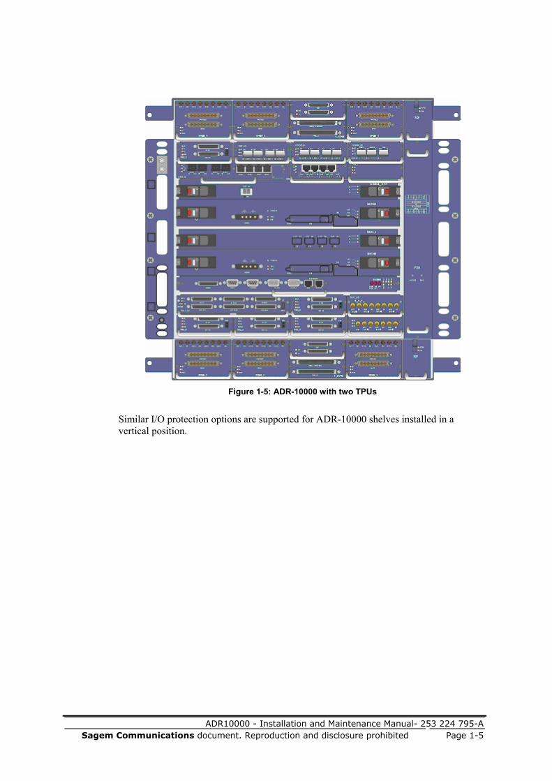
Figure 1-5: ADR-10000 with two TPUs
Similar I/O protection options are supported for ADR-10000 shelves installed in a vertical position.

ADR10000 - Installation and Maintenance Manual- 253 224 795-A
Page 1-6 Sagem Communications document. Reproduction and disclosure prohibited
ADR-10000 Shelf with one OCU and two TPUs.
An OCU can be mounted on top of the basic shelf or on top of a TPU installed on the basic shelf. The OCU can accept power amplifiers. Each expansion shelf (TPU or OCU) adds 75 mm to the height of the ADR-10000.
NOTE: The OCU is not supported for installation under the ADR-10000 shelf.
A typical ADR-10000 shelf with an OCU (and two TPUs) is shown in the following figure.
Figure 1-6: ADR-10000 with an OCU and two TPUs

ADR10000 - Installation and Maintenance Manual- 253 224 795-A Sagem Communications document. Reproduction and disclosure prohibited Page 2-1
In this chapter: Overview..........................................................................................................2-1 General Safety Requirements ..........................................................................2-2 Grounding Requirements .................................................................................2-2 Power Supply Requirements............................................................................2-4 UL Statutory Warnings and Requirements ......................................................2-4 ITU-T/Telcordia Statutory Warnings and Requirements.................................2-6 Laser Safety Requirements ..............................................................................2-7 Protection Against Electrostatic Discharge .....................................................2-9
Overview This chapter describes the ADR safety guidelines. The safety rules and warnings in this chapter must be read before beginning any shelf installation or maintenance work. These safety guidelines must be adhered to carefully.
WARNING: ADR equipment is intended for installation in restricted access areas only.
CAUTION: ADR equipment has two power sources. Disconnect both power sources before servicing.
2 Before You Start/Safety
Guidelines

ADR10000 - Installation and Maintenance Manual- 253 224 795-A
Page 2-2 Sagem Communications document. Reproduction and disclosure prohibited
General Safety Requirements ADR shelves contain power sources of varying voltages. Make sure to install the shelves in compliance with the following guidelines:
Be sure to use the equipment in restricted access locations only.
Note that the equipment racks and ADR shelves are suitable for mounting on concrete or other noncombustible surfaces only.
Ensure the integrity of the grounding connections.
ADR shelves must be installed in accordance with the National Electrical Code.
Make sure that sufficient lighting is available while working on the equipment.
Do not work on any equipment when it is connected to a voltage source (DC or AC), except for inserting/removing cards or modules; these activities can be performed on operating equipment.
Ensure that the maximum working temperature does not exceed 50°C.
Use only insulated tools during installation.
Wear protective clothing as required by the requisite safety regulations.
Do not install or maintain equipment connected to external lines (for example, E1 tributaries) during thunderstorms.
Avoid contact with high voltage sources when installing shelves, cards, and modules.
Make sure you are familiar with the warning signals and labels affixed to the equipment, and strictly observe the procedures to avoid the indicated hazards.
Grounding Requirements All equipment, including ADR shelves, ancillary units, and equipment from other vendors, must be properly grounded at all times. Good grounding is necessary to protect personnel and equipment, minimize noise, and allow the discharge of accumulated static charges to earth.
Proper operation of the ADR equipment requires that the positive supply line be connected to the common ground (CGND) of the site at the power source, in accordance with ETS300132-2.

ADR10000 - Installation and Maintenance Manual- 253 224 795-A Sagem Communications document. Reproduction and disclosure prohibited Page 2-3
Rack Grounding Requirements
The rack must be connected to the site grounding bar with a ground cable according to ETSI recommendations (top/bottom connection).
The rack is supplied with a main copper or brass grounding bolt welded to the rack frame. The grounding stud is identified on the rack by the ground symbol label.
The bolt must be free of paint. The rack grounding bolt must be connected to the site grounding bar by a grounding cable with a cross-section of the same size as the power feeding cable or thicker, and as short as possible, in compliance with UL/ETSI recommendations. The cable must be made of copper strands with a green/yellow jacket, and terminated on both sides with bolt terminals.
NOTES:
SAGEM Communications offers a few different types of (Rack Alarm Panels) RAPs: xRAP-B/BM, xRAP-HPand miniRAP for use with ADR shelves. The generic name RAP is used whenever the information applies to all types.
If necessary, the gauge of the grounding lead can also be reduced to the gauge of the RAP power leads.
The rack mounting rails must be free of paint and provide electrical continuity to the main grounding bolt. Check that the resistance between any rail and the rack main grounding bolt is lower than 0.1 Ω.
Particular attention must be paid to the area in which the RAP (when used) is attached. Paint must be removed from this area of the rack to ensure efficient electrical contact.
CAUTION: Connect the RAP grounding bolt to the rack grounding bolt with a grounding cable in compliance with UL/ETSI recommendations. The cable must include bolt terminals on both ends and be securely fastened with a nut and a star washer.

ADR10000 - Installation and Maintenance Manual- 253 224 795-A
Page 2-4 Sagem Communications document. Reproduction and disclosure prohibited
Equipment Grounding Requirements
Each equipment unit mounted on the rack is grounded to the rack frame by the retaining bolts and nuts attaching the unit to the rack frame.
Equipment grounding is performed via the mounting brackets to the rack rails. The mounting bracket's internal surface facing the rails and the equipment must be free of paint and provide electrical continuity to the equipment frame. Check that the resistance between any mounting bracket and the equipment frame (chassis) is lower than 0.1 Ω.
Power Supply Requirements
Connection via RAP
ADR shelves require two power sources with nominal voltage of -48 VDC, ranging to -57.6 VDC, having the positive line connected to the site ground.
Each power source must be protected by a UL-listed circuit breaker installed in the RAP. The required circuit breakers are included in the installation kit supplied with the equipment, and their current ratings are therefore in accordance with the order.
In addition, the site operator must provide a readily accessible UL-listed disconnect device incorporated in the fixed power wiring of the site. The device must limit the maximum delivered current to a safe value.
UL Statutory Warnings and Requirements
This section outlines the UL statutory warnings and requirements applicable to ADR platforms.
Identification of TUV CE Listing
ADR-10000 shelves are TUV CE-listed. The following is a typical TUV CE label for ADR-10000 shelves.
Figure 2-1: ADR-10000 TUV CE label

ADR10000 - Installation and Maintenance Manual- 253 224 795-A Sagem Communications document. Reproduction and disclosure prohibited Page 2-5
Warning Label
The following warning label is affixed alongside the ADR power input connectors and the RAP fuses.
Figure 2-2: Power input warning label
CAUTION: ADR equipment has two power sources. Disconnect both power sources before servicing.
UL Overcurrent Protection Requirements
NOTE: Rating and type of overcurrent protection are according to Classification Level 5 (L5) for power supplies having output circuits that meet the requirements for SELV circuits.
WARNING: When replacing fuses, observe the following precautions:
For continued protection against risk of fire, replace only with a fuse of the same type and rating.
Disconnect power before changing a fuse.
ATTENTION: Pour ne pas compromettre la protection contre les risques d’incendie, remplacer par un fusible de même type et de mêmes caractéristiques nominales.
UL Equipment Grounding Requirements
CAUTION: Observe the following equipment grounding rules:
The equipment has a connection between the grounded conductor of the DC supply circuit and the grounding conductor.
The equipment is designed to permit the connection of the grounded conductor of the DC supply circuit to the grounding conductor of the equipment.
Connect the equipment directly to the DC supply system grounding electrode conductor or to a bonding jumper from a grounding terminal bar or bus to which the DC supply system grounding electrode is connected.

ADR10000 - Installation and Maintenance Manual- 253 224 795-A
Page 2-6 Sagem Communications document. Reproduction and disclosure prohibited
Locate the equipment in the same immediate area (for example, in adjacent racks) as any other equipment that has a connection between the grounding conductor of the same DC supply circuit and the grounding conductor, and also the point of grounding of the DC system. The DC system must not be grounded elsewhere.
Position the DC supply source in the same premises as this equipment.
There must be no switching or disconnecting devices in the grounded circuit conductor between the DC source and the point of connection of the grounding electrode conductor.
UL Requirements for Grounded Conductors Connect the equipment directly to the DC supply system grounding electrode conductor or to a bonding jumper from a grounding terminal bar or bus to which the DC supply system grounding electrode conductor is connected.
Locate the DC supply source within the same premises as the equipment. There must be no switching or disconnecting devices in the grounded circuit conductor between the DC source and the point of connection of the grounding electrode conductor.
ITU-T/Telcordia Statutory Warnings and Requirements
This section outlines the ITU-T and Telcordia statutory warnings and requirements applicable to ADR platforms. The source for these requirements can be found in IEC 60950-1/3.2.1.2.
DC Supply Circuit Connection to the Grounding Conductor
WARNING: This equipment is designed to permit the connection of the grounded conductor of the DC supply circuit to the grounding conductor at the equipment. See installation instructions for more details. When this connection is made, all the following conditions must be met: This equipment shall be connected directly to the DC
supply system grounding electrode conductor, or to a bonding jumper from a grounding terminal bar or bus to which the DC supply system grounding electrode is connected.
This equipment shall be located in the same immediate area (such as adjacent cabinets) as any other equipment that has a connection between the grounded conductor of the same DC supply circuit and the grounding conductor, as well as the point of grounding of the DC system. The DC system shall not be grounded elsewhere.
The DC supply source shall be located within the same premises as this equipment.
There shall be no switching or disconnecting devices in the grounded circuit conductor between the DC source and the point of connection of the grounding electrode conductor.

ADR10000 - Installation and Maintenance Manual- 253 224 795-A Sagem Communications document. Reproduction and disclosure prohibited Page 2-7
Laser Safety Requirements
Laser Classification
The equipment and components with laser devices described in this manual comply with the International Electrotechnical Commission (IEC) safety standards, including IEC-60825-1 – Safety of Laser Products and IEC-60825-2 - Safety of Optical Fiber Communication Systems.
With specific regard to the laser, ADR-10000 equipment complies with laser product performance standards set by government agencies for Class 1 laser products. The product and its accessories do not emit hazardous light, and the beam is totally enclosed during all operating modes and maintenance.
Warning Labels for Laser Products
The following labels are affixed to the shelf front panel. The labels indicate that the product is classified as a Class 1 Laser Product, Hazard Class 1M.
LASER KLASSE1 CLASS 1 LASER PRODUCTHAZARD CLASS 1M LASER RADIATION WHEN OPEN AVOIO EXPOSURE TO THE BEAM
Laser Safety Statutory Warning
All personnel involved in equipment installation and maintenance must be aware that laser radiation is invisible. Therefore, although protective devices generally prevent direct exposure to the beam, personnel must strictly observe the applicable safety precautions and in particular must avoid staring into optical connectors, either directly or using optical instruments.

ADR10000 - Installation and Maintenance Manual- 253 224 795-A
Page 2-8 Sagem Communications document. Reproduction and disclosure prohibited
Laser Device Operating Precautions
In addition to the general precautions described in this section, be sure to observe the following warnings when operating a product equipped with a laser device. Failure to observe these warnings could result in fire, bodily injury, and damage to the equipment.
WARNING: To reduce the risk of exposure to hazardous radiation: When performing maintenance and other activities on
equipment using lasers, it is recommended that you use protection goggles for the wavelength range of 1300 nm to 1600 nm.
Only authorized personnel should carry out hot insertion or swapping of an optical module or optical interface module.
To prevent irremediable damage to your eyes, avoid looking into the fiber when hot-removing and/or inserting a fiber termination.
Place plastic covers on module fiber ports and fiber terminations which are not currently in use.
Do not operate controls, make adjustments, or perform procedures associated with the laser device other than those specified herein.
It is strictly forbidden to interfere with any protective devices and interlocks that are used to prevent direct exposure to the laser beam.
Laser information
Information regarding the various optical modules available for the ADR-10000 platform is provided in the following tables.
Table 2-1: 2.5 Gbps optical SFP transceivers for transponders/combiners
Operating output wavelength (nm)
Mode Source type Mean launched power (min./max.) (dBm)
OTR16_I3 1266-1360 Single SLM Min. -10 Max. -3
OTR16_S3 1260-1360 Single SLM Min. -5 Max. 0
OTR16_L3 1280-1335 Single SLM Min. -2 Max. +3
OTR16_L5 1500-1580 Single SLM Min. -2 Max. +3
NOTE: xx designates the transceiver’s wavelength in nm.

ADR10000 - Installation and Maintenance Manual- 253 224 795-A Sagem Communications document. Reproduction and disclosure prohibited Page 2-9
Table 2-2: GbE/FC/FICON SFP optical transceivers for transponders/combiners
Mode Data rate (nominal)
(Mbaud) Mean launched power (min./max.) (dBm)
OTGbE_SX Multimode 1250 Min. -9.5 Max. -3
OTGbE_LX Single mode 1250 Min. -11 Max. -3
OTGbE_ZX Single mode 1250 Min. -19 Max. -14
Protection against Electrostatic Discharge
This section provides guidelines regarding the protection of ADR equipment and its components against damage from electrostatic discharge (ESD) during handling, packaging/unpackaging, transportation, installation, commissioning, inspection, servicing, and maintenance works.
Electronic equipment, assemblies, and components that are sensitive to electrostatic discharge or include sensitive items are identified by the basic ESD warning symbol shown in the following figure.
Figure 2-3: Basic ESD warning symbol
The information in this section presents generally accepted workmanship practices and procedures that, when properly applied, minimize the probability of electrostatic damage to ADR equipment and its components.
The information is also in line with CENELEC Electronic Components Committee (CECC) specification CECC 00 015 that deals with protection of devices sensitive to electrostatic discharge (ESDS).

ADR10000 - Installation and Maintenance Manual- 253 224 795-A
Page 2-10 Sagem Communications document. Reproduction and disclosure prohibited
General
Most types of electronic equipment, assemblies, and components can be damaged by electrostatic discharges. An electrostatic discharge between two objects occurs when an object carrying static electrical charges touches, or is brought near enough to the other object.
Static electrical charges appear as a result of friction between surfaces of insulating materials, or separation of two such surfaces, and may also be induced by electrical fields. Routine activities such as walking across an insulating floor, friction between garment parts, friction between objects, and so on, can easily build charges up to levels that may cause damage, especially when humidity is low.
In many cases, the build-up of charges can be avoided by using special materials, for example, garments and packaging can be made of antistatic materials or materials that have high resistivity but are not insulators.
The best approach to avoiding damage by electrostatic discharges includes a combination of means and procedures that achieve the following goals:
Avoid build-up of electrostatic charges
Create a protected work environment that helps prevent electrostatic discharges
Provide means for controlled discharge of any accumulated electrostatic charges when entering the protected work environment
NOTE: An area in which equipment that is sensitive to electrostatic discharge (ESDS) can be handled with minimum risk of damage as a result of electrostatic discharge or fields, and in which the operator is not exposed to additional risks, is called an ESD Protected Area (EPA).
Personnel Training
During production and assembly, equipment is handled in work spaces especially prepared and certified to serve as a permanent EPA. However, in many cases, the environment in which the same equipment is installed or maintained cannot be assumed to form an EPA with a permanently controlled boundary.
Therefore, all the work requiring the handling of unprotected ESDS must be considered as field work.
Field work in this context includes such activities as service and maintenance, installation, site inspection, and commissioning of components and assemblies classified as ESDS, together with the packaging and unpackaging activities associated with such activities.
All the staff involved in field work must be trained to perform field work in the same way as work performed in permanent EPAs with respect to the material quality and personal responsibilities, training, labeling, and packaging.

ADR10000 - Installation and Maintenance Manual- 253 224 795-A Sagem Communications document. Reproduction and disclosure prohibited Page 2-11
Use of Temporary EPA
Where necessary, a temporary EPA must be used. A typical temporary EPA arrangement suitable for field work on ADR equipment is shown in the following figure.
The EPA tool kit includes:
Wrist strap with 1 MΩ series resistor
Bonding strap with 1 MΩ series resistor
ESD carpet (work surface), ¼ m2 minimum
The temporary EPA must include temporary controlled work surfaces and/or flooring capable of providing protection against ESD.
CAUTION: The temporary EPA must be constructed in a way that ensures electrical bonding among all the materials used, and prevents any sudden changes in potential within the EPA that could cause unacceptable voltages or discharges to be applied to the ESDS.
A means of equipotentially bonding the operator and any work surface and flooring to ground must be used. For this purpose, the work surface and wrist straps must be bonded, either to a designated ground bonding point or to the equipment being serviced, as shown in the following figure.
Whenever available, the main ground serves as the ESD grounding facility.
WARNING: While the operator is within the temporary EPA, the minimum value of resistance used for bonding to ground must limit the current to ground produced by voltages accessible to the operator to limits specified as safe by the applicable regulations (see, for example, CECC 00 015).
The same approach is applicable to the surface resistivity and resistance to ground of materials used for temporary work surfaces and flooring.
To enable ESD bonding to ground of equipment racks and any other nonmovable equipment including ESDS, an ESD ground bonding facility must be located near such equipment, or the equipment must be fitted with a designated ground bonding point presenting a resistance to ground not greater than 1 MΩ.

ADR10000 - Installation and Maintenance Manual- 253 224 795-A
Page 2-12 Sagem Communications document. Reproduction and disclosure prohibited
Figure 2-4: Typical temporary EPA arrangement
ADR-10000 with TPU
ADR-10000 with TPU

ADR10000 - Installation and Maintenance Manual- 253 224 795-A Sagem Communications document. Reproduction and disclosure prohibited Page 2-13
Work Arrangements within a Temporary EPA
To ensure that effective ESD protection is indeed achieved, the following arrangements must be observed by persons entering and/or performing field work within a temporary EPA area:
All operators working within a temporary EPA area must wear, as a minimum, an ESD antistatic protecting garment made of cotton.
If the extent of the temporary work area is such that the operator needs to walk and move within that area, then the floor must be capable of providing protection against ESD.
The operator must be bonded to ground at all times when handling an ESDS.
If it becomes necessary to remove an ESDS from equipment and transfer it to a temporary work surface away from the equipment, the ESDS must be given protective packaging unless equipotential bonding of the operator to ground is maintained.
An ESDS must be placed directly into protective packaging upon removal from equipment. A replacement ESDS must be kept in its protective packing until required for immediate installation in the equipment.
The field service operator must ensure that the materials and tools necessary to maintain and control the temporary EPA are available at the place of the field work at service time.
All tools intended for use within the EPA must, as far as is practical, be so constructed that they do not generate or hold an induced electrostatic charge.


ADR10000 - Installation and Maintenance Manual- 253 224 795-A Sagem Communications document. Reproduction and disclosure prohibited Page 3-1
In this chapter: Overview..........................................................................................................3-1 Outline of Installation Procedure.....................................................................3-9 Unpacking and Performing Visual Inspection...............................................3-11 Site Preparation..............................................................................................3-12 Tools and Test Equipment .............................................................................3-15 Preparing Cables and Fibers ..........................................................................3-15 Installation Options........................................................................................3-23 Installing Ancillary Units in Racks................................................................3-29 Installing the ADR-10000 Shelf in Racks .....................................................3-43 Grounding the ADR-10000 Shelf ..................................................................3-50 Installing ADR-10000 Cards .........................................................................3-52 Installing ADR-10000 Modules.....................................................................3-61 Installing TPU Modules.................................................................................3-67 ADR-10000 Accessories................................................................................3-73 Connecting Fibers and Cables in ETSI A Racks ...........................................3-78 Attaching TPUs/OCU to the ADR-10000 Shelf..........................................3-107
Overview This chapter provides general instructions for the installation of the ADR-10000 and auxiliary equipment.
The procedures for equipment replacement and upgrades are similar to those described for installation of the equipment, and when relevant, notes regarding live replacement or upgrade are inserted in these procedures.
The information appearing in this chapter should be used in conjunction with specific site installation plans in the particular customer network. If you are interested in obtaining design or installation assistance from SAGEM Communications Networks Solutions Division’s Customer Support team, or wish to prepare a network installation plan, contact your SAGEM Communications sales representative.
3 Equipment Installation

ADR10000 - Installation and Maintenance Manual- 253 224 795-A
Page 3-2 Sagem Communications document. Reproduction and disclosure prohibited
Preliminary Preparations
The installation procedures provided in this chapter assume that:
The sites at which the installation procedures are carried out comply with the requirements listed in Site Preparation (on page 3-12).
The preliminary preparations specified in Before You Start/Safety Guidelines (on page 2-1) have been completed.
Before you start, determine what equipment is to be installed in the rack by referring to the site installation plan, and note the exact position of each unit (to avoid errors, it is recommended that you mark the prescribed positions on the rack rails using a soft pencil).
Equipment Installation Sequence
Each component of the ADR-10000 system is supplied separately and must be installed in the correct sequence, according to the site plan.
The ADR-10000 shelf can be mounted in the rack in an horizontal or vertical position. The main equipment used for both installations is similar, and differs in the number of accessories, type of brackets used in each position, and one accessory, used only for horizontal mountings.
NOTE:
If you are not installing an FST for a particular ADR-10000 shelf, it is recommended that you leave empty space in the rack in case optical modules are added to the shelf in the future.
If you are not installing a TPU for a particular ADR-10000 shelf, it is recommended that you leave empty space in the rack so that the protection unit can be added in the future, if required, without interrupting operation.
CAUTION:
If additional equipment is used in the rack, a heat buffer or a buffer plate must be installed between any such additional equipment and the ADR-10000 shelf to minimize the transfer of heat from shelf to shelf. This heat buffer must be purchased from SAGEM Communications.
During the installation of equipment in the rack, make sure all the optical connectors are closed by protective caps. Do not remove the cap until an optical fiber is connected to the corresponding connector.
Several installation options are illustrated in Installation Options (on page 3-23).

ADR10000 - Installation and Maintenance Manual- 253 224 795-A Sagem Communications document. Reproduction and disclosure prohibited Page 3-3
ADR-10000 Horizontal Shelf and Accessories Installation Sequence
A high-density installation of a horizontal ADR-10000 shelf and corresponding accessories might include the equipment illustrated in the following figure. The different components are described alongside a number indicating the step in which the component is installed, and corresponding to the steps in the table that follows.
Figure 3-1: Components of ADR-10000 horizontal installation
ADR-10000 withTwo TPUs
ADR-10000 shelf (4) With TPUs Including:

ADR10000 - Installation and Maintenance Manual- 253 224 795-A
Page 3-4 Sagem Communications document. Reproduction and disclosure prohibited
Depending on the specific equipment being installed according to the site installation plan, the installation of an ADR-10000 system comprises the general stages in the order of execution set out in the following table.
Table 3-1: Outline of ADR-10000 horizontal installation sequence
Step Procedure Section
1. Install a rack (if required). Rack Installation (on page B-1) 2. Unpack and perform a visual inspection. Unpacking and Performing
Visual Inspection (on page 3-11) 3. Install ancillary equipment in the rack,
including: xRAP-B or xRAP Cable guides (two) Cable slack tray Fiber guides for ETSI A racks (two) FST) (optional) ODF units (optional) Optical Patch Panel (OPP)
Note: Installation of the optional xDDF-21 channel patch panel is implemented as part of the traffic cable routing process.
Installing Ancillary Units in Racks (on page 3-29)
4. Install the ADR-10000 shelf in the rack. Note: If your site installation plan includes TPU protection, the ADR-10000 is supplied with the TPU already installed. If you need to connect a TPU unit to an existing ADR-10000 shelf, see Attaching TPUs/OCU to the ADR-10000 Shelf (on page 3-107).
Installing the ADR-10000 Shelf in Racks (on page 3-43)
5. Install the air filter. Installing the Air Filter 6. Install the common cards in the ADR-
10000 shelf, including: FCU300 ECU300/ECU300-F MXC300 with NVM flash card
Installing ADR-10000 Cards (on page 3-52)
7. Install the modules in the ADR-10000 shelf, including:
Optical and electrical I/O modules (SIM, PIM)
EISMB/DIOM data modules Optical I/O cards (SIM16_4 or
SIM64_XFP) SFP transceivers in optical ADR-
10000 modules
Installing ADR-10000 Modules

ADR10000 - Installation and Maintenance Manual- 253 224 795-A Sagem Communications document. Reproduction and disclosure prohibited Page 3-5
Step Procedure Section
8. Install cards and modules in the optional TPU, including:
TC/TCF module Single-slot TPMs Double-slot TPMs Triple-slot TPMs
Installing TPU Modules (on page 3-67)
9. Install blank covers where I/O modules, cards, and TPMs are not used.
—
10. Route and connect all cables and fibers for ETSI A racks, including:
Power and alarm cables Optical fibers to optical modules
transceivers Electrical interface cables to
electrical modules (includes installation of the optional xDDF-21 channel patch panel)
Electrical traffic through the TPU Data cables to EISMB/DIOM
modules Timing cables Management cables
Connecting Fibers and Cables in ETSI A Racks (on page 3-78)
11. In some cases, it may be necessary to connect a TPU unit to an existing ADR-10000 shelf.
Attaching TPUs/OCU to the ADR-10000 Shelf (on page 3-107)

ADR10000 - Installation and Maintenance Manual- 253 224 795-A
Page 3-6 Sagem Communications document. Reproduction and disclosure prohibited
ADR-10000 Vertical Shelf and Accessories Installation Sequence
A high-density installation of a vertical ADR-10000 shelf and corresponding accessories might include the equipment illustrated in the following figure. The different components are described alongside a number indicating the step in which the component is installed, and corresponding to the steps in the table that follows.
Figure 3-2: Components of ADR-10000 vertical installation
ADR-10000 shelf (5) Including:
ADR-10000
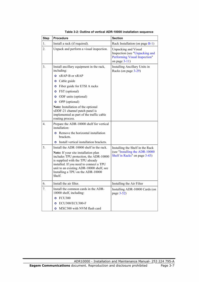
ADR10000 - Installation and Maintenance Manual- 253 224 795-A Sagem Communications document. Reproduction and disclosure prohibited Page 3-7
Table 3-2: Outline of vertical ADR-10000 installation sequence
Step Procedure Section
1. Install a rack (if required). Rack Installation (on page B-1) 2. Unpack and perform a visual inspection. Unpacking and Visual
Inspection (see "Unpacking and Performing Visual Inspection" on page 3-11)
3. Install ancillary equipment in the rack, including:
xRAP-B or xRAP Cable guide Fiber guide for ETSI A racks FST (optional) ODF units (optional) OPP (optional)
Note: Installation of the optional xDDF-21 channel patch panel is implemented as part of the traffic cable routing process.
Installing Ancillary Units in Racks (on page 3-29)
4. Prepare the ADR-10000 shelf for vertical installation:
Remove the horizontal installation brackets.
Install vertical installation brackets.
5. Install the ADR-10000 shelf in the rack. Note: If your site installation plan includes TPU protection, the ADR-10000 is supplied with the TPU already installed. If you need to connect a TPU unit to an existing ADR-10000 shelf, see Installing a TPU on the ADR-10000 Shelf.
Installing the Shelf in the Rack (see "Installing the ADR-10000 Shelf in Racks" on page 3-43)
6. Install the air filter. Installing the Air Filter 7. Install the common cards in the ADR-
10000 shelf, including: FCU300 ECU300/ECU300-F MXC300 with NVM flash card
Installing ADR-10000 Cards (on page 3-52)

ADR10000 - Installation and Maintenance Manual- 253 224 795-A
Page 3-8 Sagem Communications document. Reproduction and disclosure prohibited
Step Procedure Section
8. Install the modules in the ADR-10000 shelf, including:
Optical and electrical I/O modules (SIM, PIM)
EISMB/DIOM data modules Optical I/O cards (SIM16_4 or
SIM64_XFP) SFP transceivers in optical ADR-
10000 modules ACP100 control modules
Installing ADR-10000 Modules (see "Installing ADR-10000 Modules" on page 3-61)
9. Install cards and modules in the optional TPU, including:
TC/TCF module Single-slot TPMs Double-slot TPMs Triple-slot TPMs
Installing TPU Modules
10. Install blank covers where I/O modules, cards, and TPMs are not used.
—
11. Route and connect all cables and fibers for ETSI A racks, including:
Power and alarm cables Optical fibers to optical modules
transceivers Electrical interface cables to electrical modules (includes installation of the optional xDDF-21 channel patch panel)
Electrical traffic through the TPU Data cables to EISMB/DIOM
modules Timing cables Management cables
Connecting Fibers and Cables in ETSI A Racks (on page 3-78)
12. In some cases, it may be necessary to connect a TPU unit to an existing ADR-10000 shelf.
Installing a TPU on the ADR-10000 Shelf

ADR10000 - Installation and Maintenance Manual- 253 224 795-A Sagem Communications document. Reproduction and disclosure prohibited Page 3-9
Outline of Installation Procedure The main steps involved in the installation of an ADR-10000 shelf are listed below. Consult your site installation plans for specific details.
1. Prepare the installation site (see "Site Preparation" on page 3-12) and check physical location, environmental compliance, and availability of power sources.
2. Prepare power, alarm, and management cables at the installation site (see "Equipment Installation" on page 3-1).
3. Prepare transmission cables at the installation site.
4. Route the required power, alarm, management, and transmission cables to the intended ADR-10000 equipment location (see "Equipment Installation" on page 3-1).
5. If required, install the equipment racks (see "Rack Installation" on page B-1).
6. Mark the location of each ADR-10000 shelf and relevant accessories on each rack, in accordance with the site installation plan.
NOTE: If you are currently installing an ADR-10000 shelf without TPU protection, you may want to leave sufficient space above/under the shelf to enable the addition of the TPU/TPUs at a later stage.
7. When applicable, install the EMS-ADR management station (see the EMS-ADR User Manual).
8. Install the power distribution and alarm panels – xRAP-B/BM (on page 3-73), and other equipment needed in each rack.
9. Install the ADR-10000 shelves in the appropriate rack.
NOTE: Even if you are not currently installing an FST, it is recommended that you leave enough space above the ADR-10000 shelf to enable future installation, in case optical modules are added to the shelf at a later stage.
10. Install the ECU300/ECU300-F, FCU300, MXC300, and I/O cards in the shelf (see "Installing ADR-10000 Cards" on page 3-52).
11. Install the prescribed I/O modules in the shelf.
12. If applicable, install the TC card and the prescribed TPMs in the TPU.

ADR10000 - Installation and Maintenance Manual- 253 224 795-A
Page 3-10 Sagem Communications document. Reproduction and disclosure prohibited
13. Depending on the modules in your ADR-10000 shelf:
Route the optical fibers from the FST to the relevant module connectors.
Route the E1 electrical cables to the patch panel location.
Route the data cables to the data modules (EISMB/DIOM).
Install a patch panel for each ADR-10000 shelf where electrical E1 modules are used and 120 Ω/75 Ω conversion is required.
NOTE: The patch panel can be installed on the same rack above the ADR-10000 shelf or on a different rack.
Connect coaxial and multipair traffic cables to the electrical I/O modules if you are not using a TPU, or for modules which are not protected.
Connect both the electrical I/O modules and the coaxial and multipair traffic cables to the TPU if you are using a TPU.
Refer to the relevant section for the rack type in use (ETSI A).
14. Connect control cables between ACP100 modules, ECU300/ECU300-F, and management station.
15. Connect management cables between the equipment installed in the rack and the management station.
16. Connect power and alarm monitoring cables from the RAP panels to each ADR-10000 installed in the rack, as described in Connecting Power Cables (on page 3-79) and Connecting Alarm Cables (on page 3-79).
NOTE: In some cases, you may need to add a TPU after the ADR-10000 has already been installed. Instructions for this procedure are provided in Attaching TPUs/OCU to the ADR-10000 shelf (on page 3-107).

ADR10000 - Installation and Maintenance Manual- 253 224 795-A Sagem Communications document. Reproduction and disclosure prohibited Page 3-11
Unpacking and Performing Visual Inspection
Before you start:
Before unpacking, make a preliminary inspection of the shipping boxes. Evidence of damage should be reported immediately to the carrier, the project manager, and your local SAGEM Communications representative.
CAUTION: Static Sensitive Devices
Proper handling and grounding precautions required
ADR-10000 equipment contains components sensitive to electrostatic discharge (ESD). To prevent ESD damage, strictly observe all the precautions listed in Protection against ESD. Keep parts and cards in their antistatic packaging material until you are ready to install them.
The use of an antistatic wrist strap connected to a grounded equipment frame or rack is recommended when handling cards and modules during installation, removal, or connection to internal connectors.
You must unpack the equipment on a clean flat surface.
To unpack the equipment:
1. Place the shipping boxes with the top upwards, cut the sealing tape using a short knife so as not to damage the internal items, and open the top flaps.
2. Remove the items contained in the box and inspect each item for damage. Check for loose parts or any visual damage to the rack, shelf, and auxiliary equipment. Also check the integrity of all the connectors, leads, and cables.
NOTE: Do not remove plastic covers from optical connectors until optical cables are connected to them.
3. Search the shipping boxes for any additional small items that may be present.
4. Open each of the module and card packages for inspection, but do not remove the modules/cards from their individual protective packages until they can be inserted in the shelf.
5. Check the contents of the shipping boxes against the packing list attached to each box. If damaged parts are detected or if any parts are missing, notify the project manager and your local SAGEM Communications representative.

ADR10000 - Installation and Maintenance Manual- 253 224 795-A
Page 3-12 Sagem Communications document. Reproduction and disclosure prohibited
Site Preparation Perform a preliminary survey of the installation site, taking into consideration the following issues:
System environmental requirements
Physical location of the ADR-10000 shelves
Location of power sources
Types of interfaces used at the site (optical, electrical, management, alarm monitoring, and so on)
Work and equipment safety requirements
Environmental Requirements
The following environmental conditions must be provided at the installation site.
Parameter Compliance requirements
Electromagnetic interference FTZ 1TR9, EN 55022-2/2003, EN 50082-1/97 Temperature ETSI ETS 300-19-2-3 Test Spec. T3.1
Physical Location
WARNING: ADR-10000 shelves are intended for installation in restricted access areas only.
Choose the physical location of the ADR-10000 shelves, taking the following aspects into consideration:
1. Equipment dimensions, as specified in the following table.
2. Required floor loading capability: 150 kg per rack for a typical 4-shelf installation.
3. Routing requirements for grounding, power, alarm monitoring, and management cables, and optical fibers. To ensure convenient access to cables and fibers, it is recommended to use overhead cable ladders whenever possible, to bring the cables/fibers to the top of each rack.

ADR10000 - Installation and Maintenance Manual- 253 224 795-A Sagem Communications document. Reproduction and disclosure prohibited Page 3-13
When a network management station, for example EMS-ADR, is installed on the site, consider the method of connection to the local network management station and the maximum allowed distance.
Table 3-3: Equipment dimensions
Equipment type Height (mm)
Width (mm)
Depth (mm)
Max. weight (kg)
ADR-10000 350 443 246 8.2 (shelf only) 30 (fully populated)
TPU 75 443 246 5.5 (shelf only) 10 (fully populated)
ADR-10000 + TPU
425 443 246 13.7 (shelves only) 40 (fully populated)
ADR-10000 + two TPUs
500 443 246 21.9 (shelves only) 50 (fully populated)
ADR-10000 + two TPUs + OCU
575 443 246 30.1 (shelves only) 60 (fully populated)
xRAP-B/BM 133 445 185 9.5 xDDF-21 44.5 440 150 3

ADR10000 - Installation and Maintenance Manual- 253 224 795-A
Page 3-14 Sagem Communications document. Reproduction and disclosure prohibited
Figure 3-3: ADR-10000 horizontal installation space dimension
Power Sources
ADR equipment must be powered only by DC sources in compliance with the applicable sections of ETSI 300 132-2 and FTZ 19PFL1, and the SELV of EN 60950-1 requirements. The nominal supply voltage is -48 VDC (positive lead grounded); the allowed supply voltage range is -40 VDC to -57.6 VDC. For redundancy, two separate DC power sources should be available..
The power consumption of the ADR-10000 is:
Typical: 1100 W
Maximum: 1600 W
ADR-10000

ADR10000 - Installation and Maintenance Manual- 253 224 795-A Sagem Communications document. Reproduction and disclosure prohibited Page 3-15
NOTE: If the input power connected to one of the xINFs exceeds -57.6 VDC, both xINFs are shut down and the shelf is switched off.
Tools and Test Equipment No special-purpose tools beyond a standard technician toolbox are required for the installation of ADR-10000 shelves.
Since traffic cables can be prepared on site, suitable tool kits should also be available. This includes tools for the assembly of coaxial cables (see the following table) and tools for the preparation of optical patch cords.
Table 3-4: Recommended coaxial cable assembly tools
No. Name Description
1 Stripper DIN 1.0/2.3 2 Center contact crimp tool (blue) DIN 1.0/2.3 3 Crimp tool, outer DIN 1.0/2.3 4 Cable stripper NCX1 5 Nipper (cutter for center contact) NCX1 6 Die for NCX1 NCX1
Cleaning Optical Connectors
When handling optical fibers, clean the optical connectors using the standard cleaning kits recommended by the optical connector manufacturers.
Preparing Cables and Fibers
NOTE: This section provides information for preparing cables and optical fibers. The necessary cables can also be ordered from SAGEM Communications. For details, contact Sagem Communications Customer Support team or your Sagem Communications sales representative.
The main cables required for installing the ADR-10000 include:
Grounding cables, described in Grounding Cables (on page 3-16)
DC power cables, described in DC Power Cables (on page 3-18)
Alarm cables, described in Alarm Cables (on page 3-19)
Management cables, described in Management Cables (on page 3-20)
Timing (clock) cables, described in Timing (Clock) Cables (on page 3-20)

ADR10000 - Installation and Maintenance Manual- 253 224 795-A
Page 3-16 Sagem Communications document. Reproduction and disclosure prohibited
Electric traffic cables, described in Electric Traffic Cables (on page 3-20)
Optical fibers, described in Optical Fibers (on page 3-21)
Data cables for data modules, described in Data Cables for EISMBs and DIOMs (on page 3-22) as applicable
DC power and traffic cables should be prepared on site. AC power cables suitable for connection to the power outlet types specified when placing the order (according to the site specifications) and the control and alarm cables used within ADR equipment racks, are included in the shipment with power outlets provided according to the site specifications.
The following sections provide information to enable you to prepare cables on site. Refer to Connector Pin Assignments (on page A-1) for a description of the equipment connector types and cable wiring.
WARNING: When preparing cables, in particular power and grounding cables, use only UL-listed components of the specified types. Components must also comply with any applicable national and local safety codes and regulations.
Only qualified trained personnel may be involved in the preparation of the various cable types. Personnel must use only approved procedures, in accordance with the applicable workmanship practice.
Grounding Cables
Rack equipment is bonded through the screws that fasten the equipment chassis to the frame of the rack. Therefore, it is necessary to provide a reliable low-impedance connection between the rack frame and the site grounding bus using copper conductors.
Equipment installed in racks is bonded through the screws used to fasten the equipment chassis to the frame of the rack. Therefore, it is necessary to provide a reliable low-impedance connection between the rack frame and the site grounding bus using copper conductors.
Make the connection between the rack grounding screw and the site grounding bar by means of a copper lead with green/yellow insulation having the same diameter as the RAP input power cable or thicker, in compliance with UL/ETSI recommendations.
The end of the lead connected to a RAP, as used in the rack, must be terminated in an M8 lug.
Route grounding conductors along the shortest possible route. Treat the bare portion of the conductor with antioxidant and connect a listed two-hole compression lug. If the lug is not plated, bring it to a bright finish and coat it with antioxidant before connecting it to the frame of the rack.
WARNING: The ground cable must be of at least the same thickness as the RAP power cable.

ADR10000 - Installation and Maintenance Manual- 253 224 795-A Sagem Communications document. Reproduction and disclosure prohibited Page 3-17
WARNING: This equipment is designed to permit the connection of the grounded conductor of the DC supply circuit to the grounding conductor at the equipment. See installation instructions for more details.
When this connection is made, all of the following conditions must be met:
This equipment shall be connected directly to the DC supply system grounding electrode conductor, or to a bonding jumper from a grounding terminal bar or bus to which the DC supply system earthing electrode is connected.
This equipment shall be located in the same immediate area (such as adjacent cabinets) as any other equipment that has a connection between the grounded conductor of the same DC supply circuit and the grounding conductor, as well as the point of grounding of the DC system. The DC system shall not be grounded elsewhere.
The DC supply source shall be located within the same premises as this equipment.
There shall be no switching or disconnecting devices in the grounded circuit conductor between the DC source and the point of connection of the grounding electrode conductor.
WARNING: Cet appareil est conçu pour permettre le raccordement du conducteur relié à la terre du circuit d’alimentation c.c. au conducteur de terre de l’appareil.
Pour ce raccordement, toutes les conditions suivantes doivent être respectées:
Ce matériel doit être raccordé directement au conducteur de la prise de terre du circuit d’alimentation c.c. ou à une tresse de mise à la masse reliée à une barre omnibus de terre laquelle est raccordée à l’électrode de terre du circuit d’alimentation c.c.
Les appareils dont les conducteurs de terre respectifs sont raccordés au conducteur de terre du même circuit d’alimentation c.c. doivent être installés à proximité les uns des autres (p.ex., dans des armoires adjacentes) et à proximité de la prise de terre du circuit d’alimentation c.c. Le circuit d’alimentation c.c. ne doit comporter aucune autre prise de terre.
La source d’alimentation du circuit c.c. doit être située dans la même pièce que le matériel.
Il ne doit y avoir aucun dispositif de commutation ou de sectionnement entre le point de raccordement au conducteur de la source d’alimentation c.c. et le point de raccordement à la prise de terre.

ADR10000 - Installation and Maintenance Manual- 253 224 795-A
Page 3-18 Sagem Communications document. Reproduction and disclosure prohibited
DC Power Cables
NOTE: According to accepted industry standards for connecting DC power, the positive lead (+48 V) should be connected with a red cable, and the negative lead (-48 V) with a black cable. However, according to the BS7671 (GB) and HD 308 S2:2001 (EU) standards, the positive lead (+48 V) should be connected with a blue cable, and the negative lead (-48 V) with a gray cable. In the following sections that describe DC power cable connections, use cables with appropriate colors to comply with the standards in your area of residence.
DC power cables should be prepared on site. Two types of DC power cables are needed:
RAP input power cables
Shelf power cables
RAP input power cables
The RAP input power cables are prepared on site. They connect input power from the site power distribution subsystem to the DC input terminals of the rack's RAP panel.
Two input power cables are required for each rack, one for each source. The cables must use copper leads complying with UL/ETSI recommendations. Use a red lead for the positive conductor and a black lead for the negative conductor, or as required in your area of residence.
The RAP cable ends must be terminated in cable lugs matching the conductor gauge with M8 lugs for all RAP types (xRAP-B xRAP-HP or miniRAP).
The recommended cable gauge is 0 AWG (50 mm2/.078 inch2) or thicker for the xRAP-B or xRAP-HP, and 35 mm2 (.054 inch2) or thicker for the miniRAP. This gauge ensures that the voltage drop across the rack power cable at full power consumption does not exceed 2 V, even for cable runs up to 30 meters (99 feet) connected to a RAP providing power to two ADR shelves.
When a RAP is used to provide power to a single ADR shelf, lower lead gauges may be used:
For cable runs not exceeding 20 meters (66 feet), it is sufficient to use 16 mm2 (.025 inch2) copper leads.
For cable runs not exceeding 30 meters (99 feet), it is sufficient to use 25 mm2 (.039 inch2) copper leads.

ADR10000 - Installation and Maintenance Manual- 253 224 795-A Sagem Communications document. Reproduction and disclosure prohibited Page 3-19
NOTE: If necessary, the gauge of the grounding lead can also be reduced to the gauge of the power leads, that is, 16 mm2 (.025 inch2) for lengths up to 20 meters (66 feet), and 25 mm2 (.039 inch2) for lengths up to 30 meters (99 feet).
The ground cable must have a minimum thickness of at least 50 mm2. The ground cable must also be of at least the same thickness as the xRAP power cable. Therefore, if the xRAP power cable is thicker than 50 mm2, the grounding cable must match that thickness.
The recommended cable gauge is 2 AWG (35 mm2) or thicker. This gauge ensures that the voltage drop across the rack power cable does not exceed 2 V, even for cable runs of up to 30 meters connected to a RAP providing power to multiple ADR-10000 shelves.
When the RAP is used to provide power to a single ADR-10000 shelf, lower lead gauges may be used for runs not exceeding 50 meters. It is sufficient to use 25 m2 copper leads.
Shelf power cables
Two 12 AWG (25 mm²) cables supplied by SAGEM Communications are used to connect the two redundant input power sources from the RAP panel to the POWER connectors on the MXC300-A and MXC300-B cards of each ADR-10000 shelf installed in the rack.
Alarm Cables
Alarm cables used are included in the shipment according to the site specifications. Alarm indications are carried by the following cables:
Shelf alarm indication cable. One shelf alarm indication cable is required for each ADR-10000 shelf installed in the rack. One end of the cable is always connected to the ALARMS connector on the ECU300/ECU300-F card. Connection of the other end depends on the cable type, as follows:
xRAP-B alarm cable. Connects to one of the SHELF connectors on the xRAP-B.
Client alarm cable. Connects to the client's alarm collecting facility.
Bay alarm cable. One bay alarm cable is required for each rack. This cable carries the alarm indications and monitoring lines of the bay (rack). One end of the cable is connected to the RAP, the other end is open and connects to the client's alarm collecting facility.
xRAP-B bay alarm cable. Connects to the ALARMS connector on the xRAP-B.

ADR10000 - Installation and Maintenance Manual- 253 224 795-A
Page 3-20 Sagem Communications document. Reproduction and disclosure prohibited
Management Cables
Out-of-band management communication is connected to an ADR-10000 by means of a minihub with a pair of the RJ-45 Ethernet connectors located on the ECU300-F and ECU300 cards.
If one ADR-10000 is installed, the connection is made to the management MAIN RJ-45 connector. If more than one ADR-10000 is installed in the same site, it is possible to save the use of an external hub. In this case, the first system is connected as explained above, and the other systems are connected in an Ethernet daisy chain. The management MAIN connector of each system is connected to the management PROT/LCT connector of the previous system.
Suitable standard Ethernet station cables are available from many sources. Cables of Category 3 or better must be used. The length of the cables must not exceed the maximum recommended for the cable type and hub port in use (up to a few dozen meters).
Timing (Clock) Cables
The ECU300/ECU300-F on the ADR-10000 shelf has two timing reference connectors, T3_1/T4_1 and T3_2/T4_2, which are used for 2.048 Mbps signals and have balanced (120 Ω) G.703 interfaces.
The cables used to connect to these connectors are prepared on site, and they comprise individually shielded twisted pairs (the same type of pairs needed for connection to the balanced E1 tributary interfaces).
If the site timing reference distribution subsystem has unbalanced (75 Ω) G.703 interfaces, a 120 Ω/75 Ω adapter can be supplied for mounting on the T3_1/T4_1 and T3_2/T4_2 connectors. This permits using coaxial cables (BT3002 or equivalent) of the same type used for connecting to balanced E1 tributary interfaces.
Electric Traffic Cables
Some electric traffic cables can be prepared on site. The following table lists the type of cables and mating connectors needed for each ADR-10000 traffic interface type.
NOTE: The connectors are identical regardless of whether the traffic cables are connected directly to the I/O modules or to TPMs on the TPU.
Table 3-5: Traffic cables mating connector data
I/O module Interface type Cable type Mating connector
Qty/ Module
PIM2_63/B PIM2_63
E1 balanced (2.048 Mbps)
Twin multipair cable (2 x 21 shielded 120 Ω twisted pairs)
Twin 50-pin SCSI male
3
PIM345_3 E3 and DS-3 (34/45 Mbps)
NCX coaxial cable DIN1.0/2.3 male
6

ADR10000 - Installation and Maintenance Manual- 253 224 795-A Sagem Communications document. Reproduction and disclosure prohibited Page 3-21
I/O module Interface type Cable type Mating connector
Qty/ Module
SIM1_4/E STM-1 electrical
NCX coaxial cable DIN1.0/2.3 male
8
SIM1_81 STM-1 electrical
NCX coaxial cable DIN1.0/2.3 low profile male
16
When a TPU is used, additional patch traffic cables between PIMs and TPMs are required, as described in the following table.
Table 3-6: Patch traffic cables connecting I/O modules to the TPU
TPM Interface type Cable type Mating connector Qty/ Module
TPM2_63_2 E1 balanced (2.048 Mbps)
Triple multipair cable (21 pairs of shielded 120 Ω twisted pairs)
PIM: Triple twins of 50-pin SCSI male TPM: Twin 136-pin VHDCI male
1
TPMH_1 E3 and DS-3 (34/45 Mbps) STM-1 electrical
RG179x8 multicoaxial cable
PIM: DIN1.0/2.3 male TPM: 8W8 D-type
2
Optical Fibers
Optical fibers can be prepared on site.
Use only 2 mm optical fibers to connect to optical interfaces. For each optical interface, SAGEM Communications supplies patch cords with mating optical connectors already attached to the fiber. Therefore, only the optical termination on the ODF side, which is installation-dependent, must be installed on site.
The optical fibers should enter the rack from the top, be threaded through cable guides running along the rack side rails, and end at the FST. The tray must contain enough fiber length for extracting modules from the ADR-10000 and for replacing fiber in case of damage (splicing repairs). When routing fibers, make sure to observe the minimum bending radius (35 mm).
The following table lists the type of fibers and mating connectors needed to prepare fibers for each ADR-10000 module/card.
Table 3-7: Optical fibers and mating connector data
I/O module/card
Interface type Fiber type Mating connector
Qty/ Module/Card
SIM1_82 STM-1 optical 1 pair of fiber patch cords per interface
LC male 16 fibers
SIM4_4 STM-4 optical 1 pair of fiber patch cords per interface
LC male 8 fibers
1 SIM1_8 configured as STM-1 electrical module with ETR-1 electrical SFP transceivers. 2 SIM1_8 configured as STM-1 optical module with OTR-1 optical SFP transceivers.

ADR10000 - Installation and Maintenance Manual- 253 224 795-A
Page 3-22 Sagem Communications document. Reproduction and disclosure prohibited
I/O module/card
Interface type Fiber type Mating connector
Qty/ Module/Card
SIM16_1 STM-16 1 pair of fiber patch cords per interface
LC male 2 fibers
SIM16_4 STM-16 1 pair of fiber patch cords per interface
LC male 8 fibers
SIM64_XFP STM-64 1 pair of fiber patch cords per interface
LC male 2 fibers
Data Cables for EISMBs and DIOMs.
Data modules like EISMBs and DIOMs are connected by electrical cables or optical fibers according to the interface type being connected.
Ethernet electrical interfaces are connected by CAT5E SFTP 4-pair cables terminated with RJ-45 connectors.
Table 3-8: EISMB optical fibers and mating connector data
EISMB module
Port no. Interface type
Fiber type Mating connector
Qty/ Module
1 pair of 50/62.5 µm MM fiber, or 1 pair of 9 µm SM fiber patch cords per interface for GbE
1-2 GbE/FE
1 pair of 50/62.5 µm MM fiber patch cords per interface for FE
LC male EISMB_840
3-4 FE 1 pair of 50/62.5 µm MM fiber patch cords per interface
LC male
8 fibers
EISMB_840 can also be equipped as a mixed module including optical and electrical interfaces by inserting an electrical SFP in the port. The cabling to such port is made as a connection to an electrical interface listed in the following table.
The following table lists the type of Ethernet electrical traffic cables and the mating connectors needed for the EISMB_804 module.
Table 3-9: EISMB Ethernet electrical cables and mating connector data
EISMB module
Port no. Interface type Cable type Mating connector
Qty/ Module
1-2 10/100/1000BaseT CAT5E SFTP 4-pair
RJ-45 2 EISMB_804
3-4 10/100BaseT CAT5E SFTP 4-pair
RJ-45 2

ADR10000 - Installation and Maintenance Manual- 253 224 795-A Sagem Communications document. Reproduction and disclosure prohibited Page 3-23
Table 3-10: DIOM optical fibers and mating connector data
DIOM module
Port no. Interface type
Fiber type Mating connector
Qty/ Module
1 pair of 50/62.5 µm MM fiber, or 1 pair of 9 µm SM fiber patch cords per interface for GbE
DIOM_40 1-4 GbE/FE
1 pair of 50/62.5 µm MM fiber patch cords per interface for FE
LC male 8 fibers
DIOM_40 can also be equipped as a mixed module including optical and electrical interfaces by inserting an electrical SFP in the port. The cabling to such port is made as a connection to an electrical interface listed in the following table.
The following table lists the type of Ethernet electrical traffic cables and the mating connectors needed for the DIOM electrical modules.
Table 3-11: DIOM Ethernet electrical cables and mating connector data
DIOM module
Port no.
Interface type Cable type Mating connector
Qty/ Module
DIOM_08 1-8 10/100BaseT CAT5E SFTP 4-pair
RJ-45 8
Installation Options ADR-10000 shelves can be installed in ETSI A racks or a 19" 600 mm deep racks (in consultation with and approved by SAGEM Communications' Mechanical Department). These racks can be installed on wooden, concrete, or suspended floors, or suspended from overhead mountings.
The ADR-10000 can be installed in the rack in an horizontal or vertical position. In addition, the ADR-10000 can be expanded with one or two TPUs and an OCU. Different brackets and mechanical adapters are available for attaching the ADR-10000 to the rack in each of these positions.
NOTE: By default the ADR-10000 comes with brackets for horizontal installation in ETSI A racks. For vertical installation you must remove these brackets, and attach vertical brackets, supplied with the installation kit.
If necessary, contact SAGEM Communications' Customer Support team or your SAGEM Communications sales representative for help in meeting your specific installation requirements.
The following sections describe the installation options of the ADR-10000.

ADR10000 - Installation and Maintenance Manual- 253 224 795-A
Page 3-24 Sagem Communications document. Reproduction and disclosure prohibited
Layout of ADR-10000 Horizontal Installation in ETSI A Racks
The ADR-10000 horizontal installation in an ETSI A rack may include, in addition to the shelf itself, ancillary equipment such as RAP, cable guides for low-order and high-order traffic cables, fiber guides, cable slack tray for cables in the lower section of the ADR-10000, FST, and xDDF-21 patch panel, according to the rack installation plan. Typical installations of the ADR-10000 in a horizontal position are shown in the following figures.
Figure 3-4: Typical ADR-10000 horizontal installation
in an ETSI A rack
ADR-10000 with two TPUs
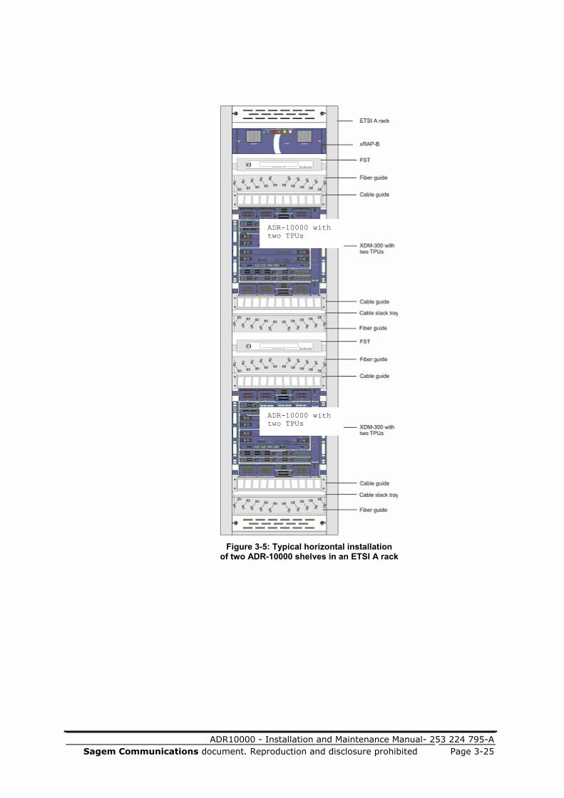
ADR10000 - Installation and Maintenance Manual- 253 224 795-A Sagem Communications document. Reproduction and disclosure prohibited Page 3-25
Figure 3-5: Typical horizontal installation
of two ADR-10000 shelves in an ETSI A rack
ADR-10000 with two TPUs
ADR-10000 with two TPUs

ADR10000 - Installation and Maintenance Manual- 253 224 795-A
Page 3-26 Sagem Communications document. Reproduction and disclosure prohibited
Figure 3-6: Typical horizontal installation
of three basic ADR-10000 shelves in 2200 mm ETSI A rack
ADR-10000
ADR-10000
ADR-10000

ADR10000 - Installation and Maintenance Manual- 253 224 795-A Sagem Communications document. Reproduction and disclosure prohibited Page 3-27
Figure 3-7: Typical horizontal installation
of three ADR-10000 shelves with TPUs in 2600 mm ETSI A rack
ADR-10000 with two TPUs
ADR-10000 with two TPUs
ADR-10000 with two TPUs

ADR10000 - Installation and Maintenance Manual- 253 224 795-A
Page 3-28 Sagem Communications document. Reproduction and disclosure prohibited
Layout of ADR-10000 Vertical Installation in ETSI A Racks
The ADR-10000 vertical installation in an ETSI A rack may include, in addition to the shelf itself, ancillary equipment such as RAP, a cable guides for low-order and high-order traffic cables, a fiber guide, FST, and xDDF-21 patch panel, according to the rack installation plan. A typical installation of the ADR-10000 in a vertical position is shown in the following figure.
Figure 3-8: Typical ADR-10000 vertical installation
in an ETSI A rack
ADR-10000

ADR10000 - Installation and Maintenance Manual- 253 224 795-A Sagem Communications document. Reproduction and disclosure prohibited Page 3-29
Installing Ancillary Units in Racks SAGEM Communications offers various accessories for efficient installation of equipment in racks. Contact SAGEM Communications Customer Support team or your SAGEM Communications sales representative if you need custom modifications to standard items or additional items.
This section includes instructions for the installation of ancillary units. The specific units you will need to install depend on your site installation plan, and may include one or more of the following:
RAP power distribution frame, usually located at the top of the rack:
xRAP-B/BM – Installing the xRAP-B/BM (on page 3-29), for connection of up to two ADR-10000 shelves on the same rack
In addition, you may need to install an xDDF-21 patch panel where PIM2_63/B is used, and where conversion between balanced 120 Ω and unbalanced 75 Ω interfaces is required. The xDDF-21 patch panel can be installed in the same rack above the ADR-10000 shelf, or in a different rack with a longer SCSI cable running from the PIM2_63/B in the ADR-10000 shelf to the patch panel.
Installation of the xDDF-21 patch panel is implemented as part of the traffic cable connection procedure described in Routing and Connecting Electrical Interface Cables to Electrical Modules (on page 3-81).
In general, ancillary units are attached to the rack side rails by four M6 Philips screws. No preparation is required before installation. The following sections provide mechanical installation instructions for units that require additional procedures. Skip sections that are not relevant to your particular application.
CAUTION: If additional equipment other than ADR-10000 shelves is used in the rack, a heat buffer must be installed between any such additional equipment and the ADR-10000 shelf to minimize the transfer of heat from shelf to shelf.
Consult your SAGEM Communications representative regarding the exact heat buffer required.
Installing the xRAP-B/BM
Before connecting DC power cables, refer to DC Power Cables (on page 3-18).
The installation of an xRAP-B/BM unit includes the following steps:
1. Prepare DC power cables.
2. Install the xRAP-B/BM in the prescribed location, either at the top of the rack or on the extendable installation rails.
3. Ground the xRAP-B/BM to the rack grounding stud.
4. Connect DC input power cables to the xRAP-B/BM. Note that when working with the xRAP-BM, there are two input power cables for each side of the xRAP-BM unit.
ADR10000 - Installation and Maintenance Manual- 253 224 795-A
Page 3-30 Sagem Communications document. Reproduction and disclosure prohibited
5. Attach protective covers to the sides and bottom of the xRAP-B/BM unit. (From V7.15 only, required for NEBS; optional for all others.)
6. Connect the DC power cables of the ADR-10000 shelves to the xRAP-B/BM.
7. Install circuit breakers.
8. Check DC voltage polarity.
9. Connect the alarm cables.
The DC input power cables connect between the two DC power sources and the xRAP-B/BM source A and source B inputs. When working with the xRAP-B, two cables are required, one for each source. When working with the xRAP-BM, four cables are required, two for each source.
NOTE: According to accepted industry standards for connecting DC power, the positive lead (+48 V) should be connected with a red cable, and the negative lead (-48 V) with a black cable. However, according to the BS7671 (GB) and HD 308 S2:2001 (EU) standards, the positive lead (+48 V) should be connected with a blue cable, and the negative lead (-48 V) with a gray cable. In the following sections that describe DC power cable connections, use cables with appropriate colors to comply with the standards in your area of residence.
Before you start:
In the xRAP-B, a single 50 mm2 cable is used for each power source. Since the xRAP-B is designed for redundancy through the use of two power sources, this means that when working in the recommended redundant mode, the xRAP-B works with two input power cables.
In the xRAP-BM, two 25 mm2 power cables should be used for each power source. When working in the recommended redundant mode with all power cables connected, the xRAP-BM works with four input power cables.
NOTE: When necessary, the xRAP-BM is able to work with only a single 25 mm2 power cable from each power source. This supplies enough power to support a single ADR platform. In many cases, when a network is using only a single ADR platform, this configuration is sufficient. However, it is recommended, if at all possible, to connect all four input power cables from the power sources to the xRAP-BM unit upon the initial system installation. Connecting all four cables from the beginning is a simple step that greatly simplifies any later system upgrades, since the power cables are already in place and ready to supply power to a second ADR platform, if the network configuration is ever changed.

ADR10000 - Installation and Maintenance Manual- 253 224 795-A Sagem Communications document. Reproduction and disclosure prohibited Page 3-31
Each input power cable consists of two stranded copper leads with a cross section of either 25 mm2 (for the xRAP-BM) or 50 mm2 (for the xRAP-B), one red and the other black. Each lead is terminated with a two-hole compression lug from the installation parts kit supplied with the equipment.
If appropriate leads have already been prepared at the prescribed rack location, make sure that the leads are not connected to any live voltage source before attaching the lugs.
To prepare a DC power cable:
1. Strip about 22 mm of the red lead jacket.
2. Insert all the lead strands into the lug sleeve.
3. Press at two or three different points on the lug sleeve using an appropriate crimping tool and die. The recommended tools are Panduit CT-720 crimping tool with CD-720-2 die, Klauke K18 crimping tool with D50 die, or equivalent.
4. Repeat Steps 1 to 3 for the black lead.
5. Repeat these steps for each DC power cable being used.
To install the xRAP-B/BM:
Attach the xRAP-B/BM to the rack side rails in the top position, and secure it with the four screws, washers, and nuts supplied in the installation parts kit.
To ground the xRAP-B/BM:
1. The xRAP-B/BM grounding stud is located on its bottom cover. Use the following figures of the xRAP-B and xRAP-BM to identify the grounding stud.
2. If necessary, prepare a grounding lead in accordance with the requirements described in Grounding Requirements.
3. Connect the lug at one end of the grounding lead to the xRAP-B/BM grounding stud using a spring washer and nut.
4. Connect the lug at the other end of the grounding lead to the rack grounding stud.
Figure 3-9: Location of xRAP-B grounding stud
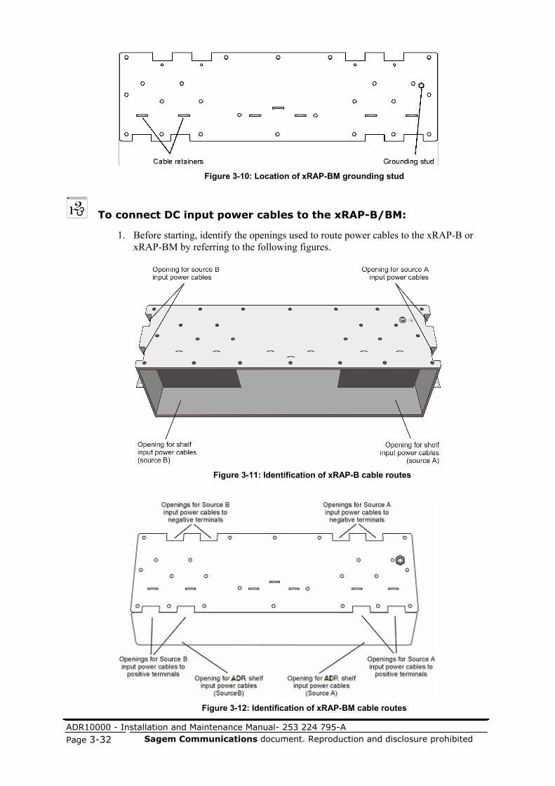
ADR10000 - Installation and Maintenance Manual- 253 224 795-A
Page 3-32 Sagem Communications document. Reproduction and disclosure prohibited
Figure 3-10: Location of xRAP-BM grounding stud
To connect DC input power cables to the xRAP-B/BM:
1. Before starting, identify the openings used to route power cables to the xRAP-B or xRAP-BM by referring to the following figures.
Figure 3-11: Identification of xRAP-B cable routes
Figure 3-12: Identification of xRAP-BM cable routes

ADR10000 - Installation and Maintenance Manual- 253 224 795-A Sagem Communications document. Reproduction and disclosure prohibited Page 3-33
2. Open the two captive screws fastening the xRAP-B/BM front cover and remove the cover.
Identify the various terminals located on the power source terminal board in accordance with the following figures. These figures show the terminals at the source A side; the same board is used at the source B side.
Figure 3-13: Connecting DC power cables
CAUTION: Before connecting the power leads, make sure to identify the terminal polarity on the xRAP-B/BM power terminal board.
3. Bring the two leads of one DC source input power cable to the appropriate xRAP-B/BM opening.
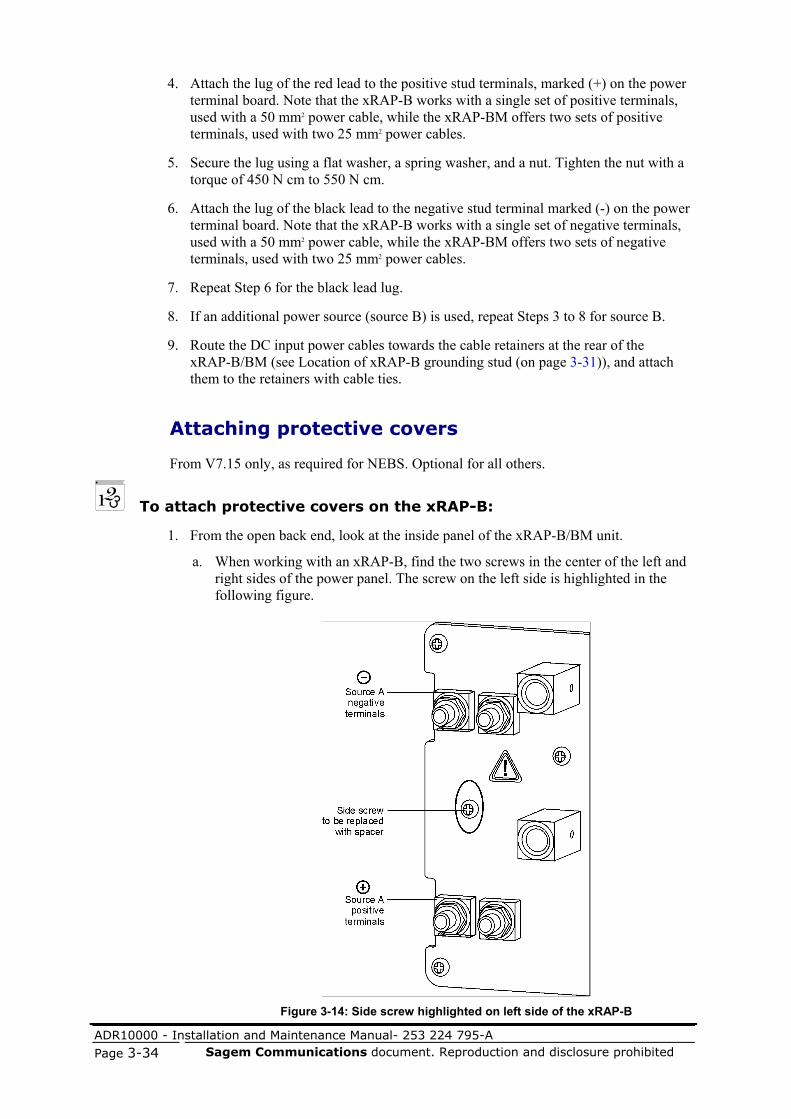
ADR10000 - Installation and Maintenance Manual- 253 224 795-A
Page 3-34 Sagem Communications document. Reproduction and disclosure prohibited
4. Attach the lug of the red lead to the positive stud terminals, marked (+) on the power terminal board. Note that the xRAP-B works with a single set of positive terminals, used with a 50 mm2 power cable, while the xRAP-BM offers two sets of positive terminals, used with two 25 mm2 power cables.
5. Secure the lug using a flat washer, a spring washer, and a nut. Tighten the nut with a torque of 450 N cm to 550 N cm.
6. Attach the lug of the black lead to the negative stud terminal marked (-) on the power terminal board. Note that the xRAP-B works with a single set of negative terminals, used with a 50 mm2 power cable, while the xRAP-BM offers two sets of negative terminals, used with two 25 mm2 power cables.
7. Repeat Step 6 for the black lead lug.
8. If an additional power source (source B) is used, repeat Steps 3 to 8 for source B.
9. Route the DC input power cables towards the cable retainers at the rear of the xRAP-B/BM (see Location of xRAP-B grounding stud (on page 3-31)), and attach them to the retainers with cable ties.
Attaching protective covers
From V7.15 only, as required for NEBS. Optional for all others.
To attach protective covers on the xRAP-B:
1. From the open back end, look at the inside panel of the xRAP-B/BM unit.
a. When working with an xRAP-B, find the two screws in the center of the left and right sides of the power panel. The screw on the left side is highlighted in the following figure.
Figure 3-14: Side screw highlighted on left side of the xRAP-B

ADR10000 - Installation and Maintenance Manual- 253 224 795-A Sagem Communications document. Reproduction and disclosure prohibited Page 3-35
b. When working with an xRAP-BM, find the four screws in the left and right sides of the power panel. The two screws on the left side are highlighted in the following figure.
Figure 3-15: Side screws highlighted on left side of xRAP-BM unit
2. Find the replacement spacer screws included in the protective cover kit. Note that two replacement spacer screws are included with the xRAP-B and four replacement spacer screws are included with the xRAP-BM. A replacement spacer screw is illustrated in the following figure.
Figure 3-16: Replacement spacer screw

ADR10000 - Installation and Maintenance Manual- 253 224 795-A
Page 3-36 Sagem Communications document. Reproduction and disclosure prohibited
3. Replace the side screws with the replacement spacer screws. The following figures illustrate the inside of the xRAP-B/BM units, highlighting the left side replacement spacer screws in place.
Figure 3-17: Replacement spacer screw in place in the xRAP-B
Figure 3-18: Replacement spacer screws in place in xRAP-BM unit
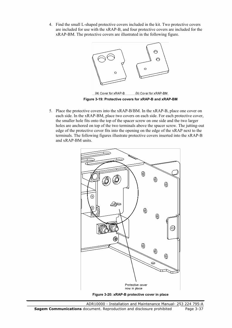
ADR10000 - Installation and Maintenance Manual- 253 224 795-A Sagem Communications document. Reproduction and disclosure prohibited Page 3-37
4. Find the small L-shaped protective covers included in the kit. Two protective covers are included for use with the xRAP-B, and four protective covers are included for the xRAP-BM. The protective covers are illustrated in the following figure.
Figure 3-19: Protective covers for xRAP-B and xRAP-BM
5. Place the protective covers into the xRAP-B/BM. In the xRAP-B, place one cover on each side. In the xRAP-BM, place two covers on each side. For each protective cover, the smaller hole fits onto the top of the spacer screw on one side and the two larger holes are anchored on top of the two terminals above the spacer screw. The jutting-out edge of the protective cover fits into the opening on the edge of the xRAP next to the terminals. The following figures illustrate protective covers inserted into the xRAP-B and xRAP-BM units.
Figure 3-20: xRAP-B protective cover in place

ADR10000 - Installation and Maintenance Manual- 253 224 795-A
Page 3-38 Sagem Communications document. Reproduction and disclosure prohibited
Figure 3-21: xRAP-BM protective covers in place
6. Secure the protective covers in place by screwing on the wing nuts supplied in the kit onto the tops of the spacer screws on each side.
7. Find the protective bottom panel in the kit. The bottom panels for the xRAP-B and xRAP-BM are illustrated in the following figure.
Figure 3-22: Bottom panels for xRAP-B and xRAP-BM
8. Secure the bottom panel into place with the four screws supplied in the kit.

ADR10000 - Installation and Maintenance Manual- 253 224 795-A Sagem Communications document. Reproduction and disclosure prohibited Page 3-39
To connect the DC power cable for an ADR-10000 shelf:
1. Before starting, identify the shelf power connectors on the xRAP-B/BM board in accordance with the following figures.
Figure 3-23: xRAP-B connectors
Figure 3-24: xRAP-BM connectors
2. Insert the end of the DC power cable terminating with a 5-pin D-type male connector near the SOURCE A power connectors and connect it to connector Shelf 1 (see preceding figures).
3. Fasten the screws of the D-type connector.
4. If you are connecting an additional shelf to the xRAP-B/BM, repeat the above steps for the shelf. Note that a maximum of 55A is supplied from the power sources to each ADR platform. Power is supplied independently to each ADR platform connected to the xRAP unit. Power is not shared between ADR platforms.
5. If an additional power source is used, repeat the above steps to connect the shelves to source B.

ADR10000 - Installation and Maintenance Manual- 253 224 795-A
Page 3-40 Sagem Communications document. Reproduction and disclosure prohibited
6. Route the DC power cables towards the cable retainers at the rear of the xRAP-B/BM and attach them to the retainers with cable ties (see Location of xRAP-B grounding stud (on page 3-31)).
7. Route each shelf power cable along the rack side rails down to the corresponding shelf position, and securely attach the power cable to the rack inner wall using cable ties. Attach a tag to each power connector in accordance with its function.
NOTE: Connect the cables to the shelves only after completing the installation of the shelves and all other components.
Installing the xRAP-B/BM circuit breakers
To install the xRAP-B/BM circuit breakers:
1. If the xRAP-B/BM front panel has not been removed, open the two captive screws fastening the xRAP-B/BM front cover to its chassis and remove the cover (see the following figures).
Figure 3-25: Installation of xRAP-B circuit breakers
ADR Shelf 1 Circuit breakear- Source A
ADR Shelf 1 Circuit breakear- Source B
ADR Shelf 2 Circuit breakear- Source B
ADR Shelf 2 Circuit breakear- Source A

ADR10000 - Installation and Maintenance Manual- 253 224 795-A Sagem Communications document. Reproduction and disclosure prohibited Page 3-41
Figure 3-26: Installation of xRAP-BM circuit breakers
2. Identify the circuit breaker corresponding to the power circuit A of shelf 1 (the circuit breaker is included in the installation parts kit supplied with the equipment); its rating is in accordance with the ordered shelf configuration.
3. Insert the circuit breaker into the circuit breaker sockets located on the xRAP-B/BM source A power terminal board, as shown in the previous figures.
4. If an additional shelf is powered from source A, repeat Steps 2 and 3 to insert the other circuit breaker into the corresponding shelf position of the power terminal board.
If an additional power source is used, repeat Steps 2, 3, and 4 for source B circuit breakers.
Table 3-12: ADR-10000 recommended circuit breakers
Shelf type Maximum power
dissipation Recommended CB per shelf
ADR-10000 basic shelf 1000 W/3415 BTU/hr
50A
ADR-10000 with TPU 1200 W/4098 BTU/hr
50A
ADR-10000 with two TPUs
1400 W/4781 BTU/hr
50A
ADR-10000 with two TPUs and one OCU
1500 W/5122 BTU/hr
50A
ADR Shelf 2 Circuit breakear- Source A
ADR Shelf 2 Circuit breakear- Source B
ADR Shelf 1 Circuit breakear- Source B
ADR Shelf 1 Circuit breakear- Source A

ADR10000 - Installation and Maintenance Manual- 253 224 795-A
Page 3-42 Sagem Communications document. Reproduction and disclosure prohibited
To check the DC voltage polarity:
1. Connect the DC input power to the xRAP-B/BM.
2. Set all xRAP-B/BM circuit breakers to ON.
3. Use a digital multimeter (DMM) to test the voltage between the positive and negative pins of each power cable.
CAUTION: Pay attention not to short-circuit the multimeter leads when checking the voltage.
NOTE: The power cable terminates with a 3-pin (3W3), or a 5-pin (5W5) connector in accordance with the connected ADR shelf. For a 3W3 connector the positive pin is A3 and the negative pin A2; for a 5W5 connector the positive pins are A4, A5, and the negative pins A2, A3.
4. Make sure the voltage is within the allowed range (-40 VDC to -57.6 VDC) and that it has the correct polarity.
5. Return all xRAP-B/BM circuit breakers to OFF.
6. Disconnect the xRAP-B/BM input power sources.
7. Reinstall the xRAP-B/BM front cover and fasten it using the two captive screws.
To connect the alarm cables to the xRAP-B/BM:
Use the figures illustrating the xRAP-B/BM connectors (in Connecting DC power cables (on page 3-33)) to identify the xRAP-B/BM connector functions.
1. Before starting, make sure you have all the necessary cables.
2. Connect the 68-pin SCSI connector of the facility alarm monitoring cable to the ALARMS connector, and then securely attach the cable to the rack inner wall using cable ties.
3. Connect the 36-pin SCSI connector of the alarm monitoring cable intended for shelf 1 to the Shelf 1 connector on the xRAP-B/BM.
4. Route the alarm cables towards the cable retainers at the rear of the xRAP-B/BM (see Location of xRAP-B grounding stud (on page 3-31)), and attach them to the bracket with cable ties.
5. Route the alarm cables along the side of the rack down to the corresponding shelf position. Attach a tag to each connector in accordance with its function.
6. If an additional shelf is installed in the rack, repeat Steps 2, 3, 4, and 5 for the cables serving the additional shelf. Make sure to attach identification tags to each cable end.

ADR10000 - Installation and Maintenance Manual- 253 224 795-A Sagem Communications document. Reproduction and disclosure prohibited Page 3-43
Installing the ADR-10000 Shelf in Racks
The ADR-10000 can be installed in the following rack types:
SAGEM Communications' recommended ETSI rack (2200 mm or 2600 mm - hereafter referred to as ETSI A), which provides the following benefits:
Removable rear and side panels for tidy routing and efficient maintenance of all rack cables, including:
E1 cables
Control cables
Power cables
Data cables
Timing cables
Two ducts on the rack’s front rails for routing up to 200 optical fibers
Open frame top and bottom for easy routing of cables from suspension floors and/or ceiling ladders
Perforated door for free air flow to the installed equipment (see Environmental Requirements (on page 3-12))
Front door for left or right opening mounting
19" 600 mm deep rack (in consultation with and approved by SAGEM Communications' Mechanical Department)
ADR-10000 equipment racks may be installed on wooden, concrete, or floating floors, or suspended from overhead mountings. For information on the various mounting options, see Rack Installation (on page B-1).
By default, ADR-10000 shelves are supplied with brackets for horizontal installation in ETSI A racks. The shelves come empty with no cards or modules installed. Therefore, the installation activities covered in this section include:
Attaching the ADR-10000 shelf to a rack. The shelf can be installed in a horizontal or vertical position.
Grounding the ADR-10000 shelf.
The installation of the ADR-10000 shelf in the vertical position requires a workaround which is described in Installing the ADR-10000 Shelf in the Vertical Position (on page 3-47).
After these procedures have been completed, the ADR-10000 shelf is ready for the installation of:
ECU300/ECU300-F, MXC300, and FCU300 cards, as described in Installing ADR-10000 Cards (on page 3-52).
I/O modules, as described in Installing ADR-10000 Modules.
TPMs in the optional TPU, as described in Installing TPU Modules.

ADR10000 - Installation and Maintenance Manual- 253 224 795-A
Page 3-44 Sagem Communications document. Reproduction and disclosure prohibited
Environmental Considerations
Observe the following guidelines when installing the ADR-10000 in racks:
1. Free airflow through the rack must be guaranteed at all times.
2. ADR-10000 shelves can be installed in open or closed (with door) racks. When installed in a closed rack, the door must be perforated. An example of a rack with a perforated door is the ETSI A rack shown in the following figure.
3. Always install the first ADR-10000 shelf in the lower part of the rack, leaving a space of at least 1U from the bottom of the rack.
4. In mixed (horizontal and vertical airflow) equipment installations, always install the equipment with the horizontal airflow (for example, ADR-10000) in the lower part of the rack, and the equipment with the vertical airflow (for example, ADR-1000) above it.
5. Leave a space of at least 1U between the upper accessory of the ADR-10000 and the next shelf.
6. Leave as much space as possible between the rack’s cable supports and the ADR-10000 sidewalls.
7. Always consider the shelf airflow requirements when organizing the cable and fiber routes near the ADR-10000 sidewalls.

ADR10000 - Installation and Maintenance Manual- 253 224 795-A Sagem Communications document. Reproduction and disclosure prohibited Page 3-45
Figure 3-27: ETSI A rack closed view
Typical ADR-10000 Installation
In addition to the ADR-10000 shelf itself, the equipment installed in the rack includes:
One Rack Alarm Panel (RAP) installed at the top of the rack, used to connect external power and alarm monitoring lines to the ADR-10000 shelves installed in the rack. The following RAP is suitable:
xRAP-B - fully supports up to two ADR-10000 shelves
In addition to the space needed for installing the RAP, you must leave at least 50 mm free space under it for routing cables.

ADR10000 - Installation and Maintenance Manual- 253 224 795-A
Page 3-46 Sagem Communications document. Reproduction and disclosure prohibited
Cable guide. Two units should be installed, one just above the ADR-10000 and one under it, to help neatly route the cables connected to the shelf.
Two fiber guides, installed one above the upper cable guide and one under the lower cable guide. Helps to neatly route fibers, while keeping the minimum allowed bend radius.
xDDF-21 (optional). A separate xDDF-21 panel can be used when unbalanced 75 Ω interfaces need to be connected and converted to balanced 120 Ω interfaces of PIM2_21 and PIM2_63/B modules. Leave at least 100 mm free space above the ADR-10000 shelf and below the xDDF-21.
NOTE: If not otherwise specified ADR-10000 shelf installations in racks shown in this manual refer to 2200 mm ETSI A racks.
Figure 3-28: Typical ADR-10000 horizontal installation in an ETSI A rack
ADR-10000 withTwo TPUs

ADR10000 - Installation and Maintenance Manual- 253 224 795-A Sagem Communications document. Reproduction and disclosure prohibited Page 3-47
Installing the ADR-10000 Shelf in the Horizontal Position
The ADR-10000 shelf comes with brackets ready for installation in ETSI A racks in the horizontal position.
To install an ADR-10000 shelf in the horizontal position in an ETSI A rack:
1. Identify the prescribed position of the ADR-10000 shelf in the rack in accordance with the rack installation plan.
2. Place the ADR-10000 shelf in the prescribed position using the two stabilizing pins to hold it temporarily in place, and then fasten the shelf to the rack side rails with four M6 screws, washers, and nuts.
Installing the ADR-10000 Shelf in the Vertical Position
Before installing the ADR-10000 shelf (in the vertical position), in an ETSI A rack, you must prepare it by performing the following steps:
Remove the horizontal installation brackets.
Install the lower vertical bracket.
Attach the vertical filter housing.
Install the upper vertical bracket.
Insert the vertical air filter.
The components required for the vertical installation are supplied in the installation kit. The procedures required for preparing the ADR-10000 for vertical installation follow.
CAUTION: When installing an ADR-10000 shelf vertically, pay attention to position the shelf with the FCU300 facing downwards. This is important to ensure proper ventilation of the ADR-10000 shelf.

ADR10000 - Installation and Maintenance Manual- 253 224 795-A
Page 3-48 Sagem Communications document. Reproduction and disclosure prohibited
To remove the ADR-10000 shelf horizontal brackets:
1. Place the ADR-10000 shelf on a flat clean surface.
2. Remove the four screws fastening the horizontal bracket to the right side of the shelf.
3. Repeat step 2 for the bracket on the left side of the shelf.
To install the vertical lower bracket:
1. Orient the ADR-10000 shelf on a flat clean surface upside down.
2. Place the vertical lower bracket on the shelf, and fit the holes in the bracket with the corresponding holes in the shelf.
Figure 3-29: Installing the vertical lower bracket
3. Fasten the lower bracket to the shelf with 11 screws from the installation kit.
NOTE: The sides of the ADR-10000 shelf described hereafter refer to the product installed in the vertical position. For example, the lower (or bottom) side of the shelf is the side near the FCU300.

ADR10000 - Installation and Maintenance Manual- 253 224 795-A Sagem Communications document. Reproduction and disclosure prohibited Page 3-49
To install the vertical upper bracket:
1. Return the ADR-10000 shelf to normal position.
2. Place the shelf near the edge of the surface to enable the lower bracket to protrude out.
3. Place the vertical upper bracket on the shelf, and fit the holes in the bracket with the corresponding holes in the shelf.
Figure 3-30: Installing the vertical upper bracket
4. Fasten the upper bracket to the shelf with seven screws and washers from the installation kit.

ADR10000 - Installation and Maintenance Manual- 253 224 795-A
Page 3-50 Sagem Communications document. Reproduction and disclosure prohibited
To attach the thumbnuts:
1. Take two thumbnuts from the installation kit and fasten them on the screws.
Figure 3-31: Installing the thumbnuts
To attach an ADR-10000 shelf in the vertical position to a rack:
1. Identify the prescribed position of the ADR-10000 shelf in the rack in accordance with the rack installation plan.
2. Place the ADR-10000 shelf in the prescribed position and then fasten the shelf to the rack side rails with eight M6 screws, washers, and nuts.
Grounding the ADR-10000 Shelf
Before you start:
Review the grounding requirements specified in Grounding Requirements (on page 2-2) and Preparing Cables and Fibers (on page 3-15). Obtain the required materials and make sure to perform the grounding connections in accordance with these requirements.

ADR10000 - Installation and Maintenance Manual- 253 224 795-A Sagem Communications document. Reproduction and disclosure prohibited Page 3-51
WARNING:
The ground cable must be of at least the same thickness as the xRAP power cable. Therefore, if the xRAP power cable is thick, the grounding cable must match that thickness.
The thickness of the shelf grounding cable must match the thickness of the power cable from the xRAP to the shelf.
To ground the ADR-10000:
1. Connect the rack grounding stud to the site grounding bar, as illustrated in the following figure.
Figure 3-32: ADR-10000 shelf and rack grounding

ADR10000 - Installation and Maintenance Manual- 253 224 795-A
Page 3-52 Sagem Communications document. Reproduction and disclosure prohibited
2. Connect the RAP grounding post to the rack grounding stud.
3. When NEBS compliance is required, for each ADR-10000 shelf installed in the rack, connect a grounding strap from the two shelf grounding posts to the RAP grounding post. Note that the grounding strap lug must be inserted over both grounding posts.
Installing ADR-10000 Cards After the shelf has been installed and grounded, you can install the cards.
Before you start:
When installing cards, make sure to carefully align the card with the shelf guide rails. Hold the card straight during insertion and removal, and pull or push it slowly and carefully to avoid touching components located on adjacent cards/modules.
CAUTION:
If you feel resistance when inserting cards, immediately retract the card and repeat the process.
Do not use excessive torque when tightening the fastening card screws.
FCU300 Card
The FCU300 card is installed in the rightmost vertical slot of the ADR-10000.
Figure 3-33: Installing the FCU300

ADR10000 - Installation and Maintenance Manual- 253 224 795-A Sagem Communications document. Reproduction and disclosure prohibited Page 3-53
To install the FCU300 card:
1. Check that the FCU300 has not been physically damaged during shipment, and that the antistatic protection bag of the original packaging is sealed.
2. Remove the FCU300 from its antistatic protection packaging and perform a visual inspection to detect damage during shipping. Report any problems.
3. Record the hardware version indicated on the unit’s identification label.
4. Insert the rear end of the FCU300 into the card guides.
5. Push the FCU300 in until it mates the chassis connectors and the front of the card is flush with the front of the ADR-10000 shelf. If you feel resistance before the connectors are mated, pull the fan unit out and repeat the procedure.
6. Secure the FCU300 in place by tightening the two captive screws.
ECU300 Card
The ECU300 card is installed in the bottom horizontal slot of the card cage. Installation is identical for the ECU300-F and ECU300 cards.
Figure 3-34: Installing the ECU300/ECU300-F
CAUTION: Take care not to change the position of the ECU300/ECU300-F switches when inserting or removing a card. Always hold the ECU300/ECU300-F by grasping the sides of the card without touching any of the internal electronics or front panel switches and connectors.

ADR10000 - Installation and Maintenance Manual- 253 224 795-A
Page 3-54 Sagem Communications document. Reproduction and disclosure prohibited
To install the ECU300/ECU300-F card:
1. Check that the card has not been physically damaged during shipment, and that the antistatic protection bag of the original packaging is sealed.
2. Remove the card from its antistatic protection packaging and perform a visual inspection to detect damage during shipping. Report any problems.
3. Record the hardware and software versions indicated on the card’s identification labels.
4. Insert the rear end of the ECU300/ECU300-F into the card guides.
5. Push the ECU300/ECU300-F in until it mates the chassis connectors and the front of the card is flush with the front of the ADR-10000 shelf. If you feel resistance before the connectors are mated, pull the card out and repeat the procedure.
6. Secure the ECU300/ECU300-F in place by tightening the two captive screws.
MXC300 Card
The ADR-10000 shelf always operates as redundant platforms, therefore each shelf must be equipped with two MXC300 cards installed, one in slot MXC-A (main card) and one in slot MXC-B (protection card).
Figure 3-35: Installing the MXC300
CAUTION: Before extracting or inserting an MXC300 into the shelf, release the extractor handles by pressing the brown locks outward first, then pull/push both handles simultaneously. Failure to do so may damage the card.

ADR10000 - Installation and Maintenance Manual- 253 224 795-A Sagem Communications document. Reproduction and disclosure prohibited Page 3-55
To install the MXC300 card:
1. Check that the card has not been physically damaged during shipment, and that the antistatic protection bag of the original packaging is sealed.
2. Remove the card from its antistatic protection packaging and perform a visual inspection to detect damage during shipping. Report any problems.
3. Record the hardware and software versions indicated on the card’s identification labels.
4. Press both brown levers located on the card's extractor handles to release the handles.
5. Simultaneously push both handles forward.
6. Insert the rear end of the MXC300 card into the card guides.
7. If the NVM card was not installed in the MXC300, install it as follows:
a. Check that the NVM card has not been physically damaged during shipment.
b. Remove the NVM from its antistatic protection packaging and perform a visual inspection to detect damage during shipment. Report any problems.
Figure 3-36: Installing the NVM in the MXC300
c. Orient the NVM card against the dedicated slot on the MXC300, and then insert its rear end (the end with the connector) in the card guides. Push the card in until it is locked in place.
NOTE: If the NVM lock is not properly fastened, there is no access to read/write and the system emits an NVM “Cardout” alarm.
d. Place the NVM cover on the slot, and fasten it with its two captive screws.

ADR10000 - Installation and Maintenance Manual- 253 224 795-A
Page 3-56 Sagem Communications document. Reproduction and disclosure prohibited
8. Push the front panel of the MXC300 in until the extractor handles start to move inside, the card mates the chassis connectors, and the front of the card is flush with the front of the shelf. If you feel resistance before the connectors are mated, pull the card out and repeat the procedure.
9. Turn the two extractor handles simultaneously to the horizontal position to lock the card in place.
10. Secure the MXC300 in place by tightening the two captive screws.
NOTE: Make sure that card is properly locked in place. Failure to do so may result in improper operation of the shelf.
If the FAIL (red), MAIN (blue), and TMU (orange) LEDs blink simultaneously, the MXC300 is not mounted correctly or the extractor handles are not properly locked.
CAUTION: When replacing any MXC300 card:
The brown levers on the extractor handles operate microswitches that indicate to the ADR-10000 platform that the MXC300 card is installed. These levers must be pressed first when replacing an MXC300.
WARNING:
To reset the system using the RESET button, you must first remove the NVM cover.
To extract the NVM, press the release pushbutton using the cover as a tool.

ADR10000 - Installation and Maintenance Manual- 253 224 795-A Sagem Communications document. Reproduction and disclosure prohibited Page 3-57
Quad I/O Cards
Quad I/O cards (SIM16_4 or SIM64_XFP) can be installed in two dedicated slots (I17, I18) called quad slots (as they occupy the space of four I/O module slots) in the ADR-10000. When quad I/O cards are not needed, these slots can be utilized to install SIM16_1 modules by adding a mechanical adapter.
Figure 3-37: Installing a quad I/O card
NOTE: When quad I/O cards or SIM16_1 modules are not installed in slots I17, I18, the openings must be covered with blank panels to avoid cooling air escape and comply with electromagnetic compatibility (EMC).
To install a quad I/O card:
1. Check that the card has not been physically damaged during shipment, and that the antistatic protection bag of the original packaging is sealed.
2. Remove the card from its antistatic protection packaging and perform a visual inspection to detect damage during shipping. Report any problems.
3. Record the hardware and software versions indicated on the card’s identification labels.
CAUTION: Before extracting or inserting a quad I/O card into the shelf, release the extractor handles by pressing the brown locks outward first and then pull/push both handles simultaneously. Failure to do so may damage the card.
4. Push both brown levers located on the card's extractor handles to release the handles.
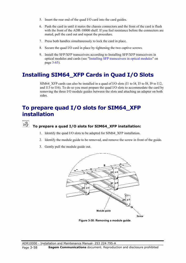
ADR10000 - Installation and Maintenance Manual- 253 224 795-A
Page 3-58 Sagem Communications document. Reproduction and disclosure prohibited
5. Insert the rear end of the quad I/O card into the card guides.
6. Push the card in until it mates the chassis connectors and the front of the card is flush with the front of the ADR-10000 shelf. If you feel resistance before the connectors are mated, pull the card out and repeat the procedure.
7. Press both handles simultaneously to lock the card in place.
8. Secure the quad I/O card in place by tightening the two captive screws.
9. Install the SFP/XFP transceivers according to Installing SFP/XFP transceivers in optical modules and cards (see "Installing SFP transceivers in optical modules" on page 3-65).
Installing SIM64_XFP Cards in Quad I/O Slots
SIM64_XFP cards can also be installed in a quad of I/O slots (I1 to I4, I5 to I8, I9 to I12, and I13 to I16). To do so you must prepare the quad I/O slots to accommodate the card by removing the three I/O module guides between the slots and attaching an adapter on both sides.
To prepare quad I/O slots for SIM64_XFP installation
To prepare a quad I/O slots for SIM64_XFP installation:
1. Identify the quad I/O slots to be adapted for SIM64_XFP installation.
2. Identify the module guide to be removed, and remove the screw in front of the guide.
3. Gently pull the module guide out.
Figure 3-38: Removing a module guide

ADR10000 - Installation and Maintenance Manual- 253 224 795-A Sagem Communications document. Reproduction and disclosure prohibited Page 3-59
4. Repeat steps 2 and 3 for the two other module guides.
5. Identify the SIM64_XFP right adapter according to the following figure.
Figure 3-39: Installing the SIM64_XFP right adapter
6. Attach the adapter to the right side of the quad I/O slots with two screws from the installation kit as shown in the figure above.
7. Identify the left card adapter according to the following figure.
Figure 3-40: Installing the SIM64_XFP left adapter
8. Attach the adapter to the left side of the quad I/O slots with two screws from the installation kit as shown in the figure above.

ADR10000 - Installation and Maintenance Manual- 253 224 795-A
Page 3-60 Sagem Communications document. Reproduction and disclosure prohibited
To install a SIM64_XFP in a quad I/O slots:
1. Check that the card has not been physically damaged during shipment, and that the antistatic protection bag of the original packaging is sealed.
2. Remove the card from its antistatic protection packaging and perform a visual inspection to detect damage during shipping. Report any problems.
3. Record the hardware and software versions indicated on the card’s identification labels.
4. Check that the quad I/O slots have been prepared to accommodate the SIM64_XFP, as described in To prepare quad I/O slots for SIM64_XFP installation (on page 3-58).
CAUTION: Before extracting or inserting a SIM64_XFP card into the shelf, release the extractor handles by pressing the brown locks outward first and then pull/push both handles simultaneously. Failure to do so may damage the card.
5. Push both brown levers located on the card's extractor handles to release the handles.
6. Insert the rear end of the SIM64_XFP into the card guides.
Figure 3-41: Installing a SIM64_XFP in a quad I/O slot
7. Push the card in until it mates the chassis connectors and the front of the card is flush with the front of the ADR-10000 shelf. If you feel resistance before the connectors are mated, pull the card out and repeat the procedure.
8. Press both handles simultaneously to lock the card in place.
9. Secure the SIM64_XFP in place by tightening the two captive screws.
10. Install the XFP transceiver according to Installing SFP/XFP transceivers in optical modules and cards (see "Installing SFP transceivers in optical modules" on page 3-65).
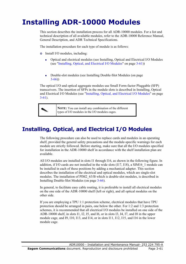
ADR10000 - Installation and Maintenance Manual- 253 224 795-A Sagem Communications document. Reproduction and disclosure prohibited Page 3-61
Installing ADR-10000 Modules This section describes the installation process for all ADR-10000 modules. For a list and technical description of all available modules, refer to the ADR-10000 Reference Manual, General Description, and ADR Technical Specifications.
The installation procedure for each type of module is as follows:
Install I/O modules, including:
Optical and electrical modules (see Installing, Optical and Electrical I/O Modules (see "Installing, Optical, and Electrical I/O Modules" on page 3-61))
Double-slot modules (see Installing Double-Slot Modules (on page 3-66))
The optical I/O and optical aggregate modules use Small Form-factor Pluggable (SFP) transceivers. The insertion of SFPs in the module slots is described in Installing, Optical and Electrical I/O Modules (see "Installing, Optical, and Electrical I/O Modules" on page 3-61).
NOTE: You can install any combination of the different types of I/O modules in the I/O modules cages.
Installing, Optical, and Electrical I/O Modules
The following procedure can also be used to replace cards and modules in an operating shelf, provided the general safety precautions and the module-specific warnings for each module are strictly followed. Before starting, make sure that all the I/O modules specified for installation in the ADR-10000 shelf in accordance with the shelf installation plan are available.
All I/O modules are installed in slots I1 through I16, as shown in the following figure. In addition, if I/O cards are not installed in the wide slots (I17, I18), a SIM16_1 module can be installed in each of these positions by adding a mechanical adapter. This section describes the installation of the electrical and optical modules, which are single-slot modules. The installation of PIM2_63/B which is double-slot modules, is described in Installing Double-Slot Modules (on page 3-66).
In general, to facilitate easy cable routing, it is preferable to install all electrical modules on the one side of the ADR-10000 shelf (left or right), and all optical modules on the other side.
If you are employing a TPU 1:1 protection scheme, electrical modules that have TPU protection should be arranged in pairs, one below the other. For 1:2 and 1:3 protection schemes, it is recommended that all electrical I/O modules be installed on one side of the ADR-10000 shelf, in slots I1, I2, I5, and I6, or in slots I3, I4, I7, and I8 in the upper module cage, and I9, I10, I13, and I14, or in slots I11, I12, I15, and I16 in the lower module cage.

ADR10000 - Installation and Maintenance Manual- 253 224 795-A
Page 3-62 Sagem Communications document. Reproduction and disclosure prohibited
CAUTION:
When installing optical modules, make sure all SFP transceiver slots are closed by protective caps. Do not remove the cover until an SFP is inserted.
For your safety, to comply with electro-magnetic compatibility (EMC) requirements and to prevent escape of ventilation from the fans through these openings, protect all unused slots with blank panels.
Figure 3-42: Inserting an I/O module in the I/O slots
To install an I/O electrical and optical module in the module cages:
1. Check that the module has not been physically damaged during shipment, and that the antistatic protection bag of the original packaging is sealed.
2. Remove the module from its antistatic protection packaging and perform a visual inspection to detect damage during shipping. Report any problems.
3. Record the hardware and software versions indicated on the module’s identification labels.
4. Identify the assigned slot, and insert the rear end of the module into the corresponding module guides.
5. Push the module into the guides of the appropriate slot. Push slowly backwards to mate the connectors until the front of the module is flush with the front of the ADR-10000 shelf. Make sure the two fastening screws are free to move backward as the module slides in. If you feel resistance before the connectors are fully mated, retract the module and repeat the procedure.

ADR10000 - Installation and Maintenance Manual- 253 224 795-A Sagem Communications document. Reproduction and disclosure prohibited Page 3-63
CAUTION: When inserting a module, make sure to carefully align it with the cage guide rails. If you feel resistance during insertion, immediately retract the module and repeat the process.
Hold the module straight during insertion and removal. Pull or push it slowly and carefully to avoid touching components on adjacent modules.
6. Fasten the module to the chassis by tightening the two fastening screws. Do not use excessive torque when tightening the screws.
7. If you are installing an optical, or mixed module with SFP transceivers, proceed to Installing SFP/XFP transceivers in optical modules and cards (see "Installing SFP transceivers in optical modules" on page 3-65).
After inserting all the modules, check for correct installation against the module insertion diagram. Install blank panels over all free slots.
Installing SIM16_1 modules in quad slots
The quad slots I17 and I18 can be adapted to accommodate one SIM16_1 each by installing a mechanical adapter.
Figure 3-43: Installing the SIM16_1 mechanical adapter

ADR10000 - Installation and Maintenance Manual- 253 224 795-A
Page 3-64 Sagem Communications document. Reproduction and disclosure prohibited
To install the SIM16_1 mechanical adapter:
1. Check that the adapter has not been physically damaged during shipment, and that the packaging bag of the original packaging is sealed.
2. Remove the adapter from its protection packaging and perform a visual inspection to detect damage during shipping. Report any problems.
3. Insert the rear end of the adapter into the card guides.
4. Push the adapter in until the front of it is flush with the front of the ADR-10000 shelf. If you feel resistance before the adapter is in place, pull it out and repeat the procedure.
5. Secure the adapter in place by tightening the two captive screws.
To install a SIM16_1 module in a quad slot:
1. Check that the SIM16_1 mechanical adapter is properly installed in the corresponding quad slot.
2. Check that the SIM16_1 module has not been physically damaged during shipment, and that the antistatic protection bag of the original packaging is sealed.
3. Remove the module from its antistatic protection packaging and perform a visual inspection to detect damage during shipping. Report any problems.
4. Record the hardware and software versions indicated on the module’s identification labels.
5. Insert the rear end of the SIM16_1 into the module guides in the mechanical adapter.
6. Push the module into the guides of the appropriate slot. Push slowly backwards to mate the connectors until the front of the module is flush with the front of the adapter. Make sure the two fastening screws are free to move backward as the module slides in. If you feel resistance before the connectors are fully mated, retract the module and repeat the procedure.
CAUTION: When inserting a module, make sure to carefully align it with the adapter guide rails. If you feel resistance during insertion, immediately retract the module and repeat the process.
Hold the module straight during insertion and removal. Pull or push it slowly and carefully until it is in the correct position.
7. Fasten the module to the adapter by tightening the two fastening screws. Do not use excessive torque when tightening the screws.
8. Install the SFP transceiver according to Installing SFP/XFP transceivers in optical/CWDM modules and cards (see "Installing SFP transceivers in optical modules" on page 3-65).

ADR10000 - Installation and Maintenance Manual- 253 224 795-A Sagem Communications document. Reproduction and disclosure prohibited Page 3-65
Installing SFP transceivers in optical modules
CAUTION: During the installation of SFP/XFP transceivers in optical or CWDM modules and cards, make sure that all optical LC connectors are closed by protective caps. Do not remove the covers until an optical fiber is connected to the corresponding connector.
To install SFP/XFP transceivers in optical I/O modules and cards:
1. Identify the prescribed position on the module according to the site installation plan.
2. Check that the SFP/XFP has not been physically damaged during shipment, and that the antistatic protection bag of the original packaging is sealed.
3. Remove the SFP/XFP from its antistatic protection packaging and perform a visual inspection to detect damage during shipping. Report any problems.
4. Record the hardware and software versions indicated on the SFP/XFP identification labels.
5. Remove the protective covers from the slot and from the SFP/XFP transceiver.
6. Insert the rear end of the transceiver into the slot guides, and push slowly backwards to mate the connectors until the transceiver clicks into place. If you feel resistance before the connectors are fully mated, retract the transceiver and repeat the procedure.
Figure 3-44: Inserting an SFP/XFP transceiver into an I/O module
CAUTION: All slots that are not in use must remain covered. If you have to replace a module or card, remove the SFP/XFP first.

ADR10000 - Installation and Maintenance Manual- 253 224 795-A
Page 3-66 Sagem Communications document. Reproduction and disclosure prohibited
Installing Double-Slot Modules
Before you start:
Make sure that all the double-slot modules (PIM2_63s) specified for installation in the ADR-10000 shelf in accordance with the shelf installation plan, are available.
Figure 3-45: Installation of typical double-slot modules in the ADR-10000
Because the PIM 2_63s occupy a pair of slots each, before you can install them you must first remove the guide between the pair of slots.
To remove a module guide from the lower row of slots:
1. Identify the module guide you are removing and remove the screw from the front of the guide.
2. Gently pull the module guide out.
Figure 3-46: Removing the module guide

ADR10000 - Installation and Maintenance Manual- 253 224 795-A Sagem Communications document. Reproduction and disclosure prohibited Page 3-67
CAUTION: Do not allow the metal part you are removing to touch any modules or other parts of the ADR-10000 cage. This may cause a short-circuit and damage the modules.
To install a double-slot module in the modules cage:
1. Check that the module has not been physically damaged during shipment, and that the antistatic protection bag of the original packaging is sealed.
2. Remove the module from its antistatic protection packaging and perform a visual inspection to detect damage during shipping. Report any problems.
3. Record the hardware and software versions indicated on the module’s identification labels.
4. Identify the assigned slot and insert the rear end of the module into the corresponding module guides.
5. Push the module in until it mates the chassis connectors and the front of the module is flush with the front of the ADR-10000 shelf. Make sure the two fastening screws are free to move backward as the module slides in. If you feel resistance before the connectors are mated, pull the module out and repeat the procedure.
6. Fasten the module to the chassis by tightening the two fastening screws.
7. If you are installing MCSMs with SFP transceivers, proceed to Installing, Optical, CWDM and Electrical I/O Modules (see "Installing, Optical and Electrical I/O Modules" on page 3-61).
NOTE: Only FE SFP transceivers can be inserted into FE ports; you can insert either GbE SFP or FE SFP transceivers into GbE/FE ports.
8. After inserting all the modules, check for correct installation against the module insertion diagram. Install blank panels over all free slots.
Installing TPU Modules This section provides instructions for:
Installing the TC/TCF Module in the TPU Shelf (on page 3-68)
Installing Single-Slot TPMs in the TPU (on page 3-69)
Installing Optical Amplifiers in the TPU (on page 3-70)
Installing Double-Slot TPMs in the TPU (on page 3-70)
Installing Triple-Slot TPMs in the TPU (on page 3-71)

ADR10000 - Installation and Maintenance Manual- 253 224 795-A
Page 3-68 Sagem Communications document. Reproduction and disclosure prohibited
Before you start:
Make sure that the TC/TCF module and all the TPMs specified for installation in the ADR-10000 shelf in accordance with the shelf installation plan are available.
Installing the TC/TCF Module in the TPU Shelf
The TC/TCF module is installed in the right slot of the TPU.
Figure 3-47: Inserting the TC module (ADR-10000)
To install a TC/TCF module in the TPU:
1. Check that the module has not been physically damaged during shipment, and that the antistatic protection bag of the original packaging is sealed.
2. Remove the module from its antistatic protection packaging and perform a visual inspection to detect damage during shipping. Report any problems.
3. Record the hardware and software versions indicated on the module’s identification labels.
4. Identify the assigned slot, and insert the rear end of the module into the corresponding TC/TCF module guides.
5. Push the module in until it mates the chassis connectors and the front of the module is flush with the front of the ADR-10000 shelf. Make sure the two fastening screws are free to move backward as the TC/TCF module slides in. If you feel resistance before the connectors are mated, pull the module out and repeat the procedure.

ADR10000 - Installation and Maintenance Manual- 253 224 795-A Sagem Communications document. Reproduction and disclosure prohibited Page 3-69
6. Fasten the module to the chassis by tightening the two fastening screws.
Installing Single-Slot TPMs in the TPU
This section describes the installation of single-slot (1:1 protection) modules. The installation of double-slot (1:3 protection) modules is described in Installing Double-Slot TPMs in the TPU (on page 3-70).
Figure 3-48: Inserting a single-slot TPM in the TPU (ADR-10000)
To install a single-slot TPM in the TPU:
1. Check that the module has not been physically damaged during shipment, and that the antistatic protection bag of the original packaging is sealed.
2. Remove the module from its antistatic protection packaging and perform a visual inspection to detect damage during shipping. Report any problems.
3. Record the hardware and software versions indicated on the module’s identification labels.
4. Identify the assigned slot, and insert the rear end of the module into the corresponding module guides.
5. Push the module in until it mates the chassis connectors and the front of the module is flush with the front of the ADR-10000 shelf. Make sure the two fastening screws are free to move backward as the module slides in. If you feel resistance before the connectors are mated, pull the module out and repeat the procedure.
6. Fasten the module to the chassis by tightening the two fastening screws.
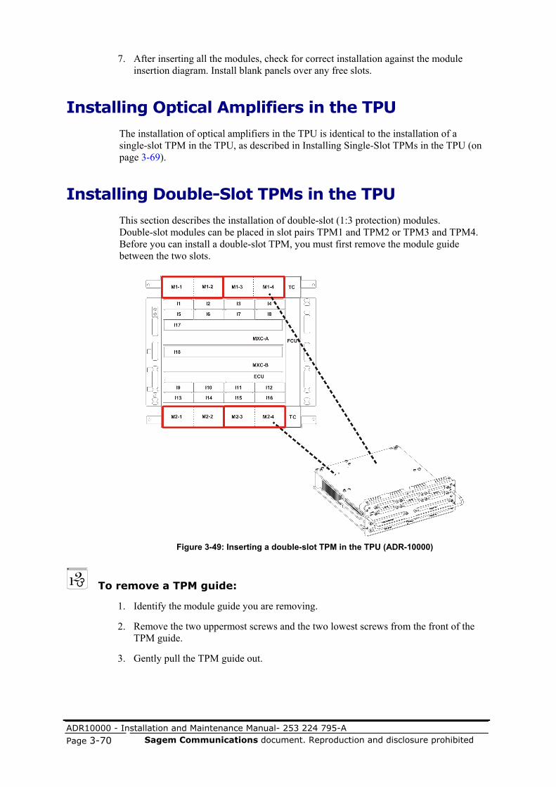
ADR10000 - Installation and Maintenance Manual- 253 224 795-A
Page 3-70 Sagem Communications document. Reproduction and disclosure prohibited
7. After inserting all the modules, check for correct installation against the module insertion diagram. Install blank panels over any free slots.
Installing Optical Amplifiers in the TPU
The installation of optical amplifiers in the TPU is identical to the installation of a single-slot TPM in the TPU, as described in Installing Single-Slot TPMs in the TPU (on page 3-69).
Installing Double-Slot TPMs in the TPU
This section describes the installation of double-slot (1:3 protection) modules. Double-slot modules can be placed in slot pairs TPM1 and TPM2 or TPM3 and TPM4. Before you can install a double-slot TPM, you must first remove the module guide between the two slots.
Figure 3-49: Inserting a double-slot TPM in the TPU (ADR-10000)
To remove a TPM guide:
1. Identify the module guide you are removing.
2. Remove the two uppermost screws and the two lowest screws from the front of the TPM guide.
3. Gently pull the TPM guide out.

ADR10000 - Installation and Maintenance Manual- 253 224 795-A Sagem Communications document. Reproduction and disclosure prohibited Page 3-71
Figure 3-50: Removing a TPM guide
To install a double-slot TPM in the TPU:
1. Check that the module has not been physically damaged during shipment, and that the antistatic protection bag of the original packaging is sealed.
2. Remove the module from its antistatic protection packaging and perform a visual inspection to detect damage during shipping. Report any problems.
3. Record the hardware and software versions indicated on the module’s identification labels.
4. Identify the assigned slot, and insert the rear end of the module into the corresponding module guides.
5. Push the module in until it mates the chassis connectors and the front of the module is flush with the front of the ADR-10000 shelf. Make sure the two fastening screws are free to move backward as the module slides in. If you feel resistance before the connectors are mated, pull the module out and repeat the procedure.
6. Fasten the module to the chassis by tightening the two fastening screws.
7. After inserting all modules, check for correct installation against the module insertion diagram. Install blank panels over any free slots.
Installing Triple-Slot TPMs in the TPU
This section describes the installation of triple-slot (1:2 protection) modules, which are accommodated in slots TPM1, TPM2, and TPM3 (slot TPM4 remains free).
Before you start:
1. Before installing a triple-slot TPM, remove the two module guides between the three slots. See To remove a TPM guide (on page 3-70).

ADR10000 - Installation and Maintenance Manual- 253 224 795-A
Page 3-72 Sagem Communications document. Reproduction and disclosure prohibited
2. Make sure that all the TPMs specified for installation in the ADR-10000 in accordance with the shelf installation plan are available.
Figure 3-51: Inserting a triple-slot TPM in the TPU (ADR-10000)
To install a triple-slot TPM in the TPU:
1. Check that the module has not been physically damaged during shipment, and that the antistatic protection bag of the original packaging is sealed.
2. Remove the module from its antistatic protection packaging and perform a visual inspection to detect damage during shipping. Report any problems.
3. Record the hardware and software versions indicated on the module’s identification labels.
4. Identify the assigned slot, and insert the rear end of the module into the corresponding module guides.
5. Push the module in until it mates the chassis connectors and the front of the module is flush with the front of the ADR-10000 shelf. Make sure the two fastening screws are free to move backward as the module slides in. If you feel resistance before the connectors are mated, pull the module out and repeat the procedure.
6. Fasten the module to the chassis by tightening the two fastening screws.
7. After inserting the modules, check for correct installation against the module insertion diagram. Install blank panels over any free slots.

ADR10000 - Installation and Maintenance Manual- 253 224 795-A Sagem Communications document. Reproduction and disclosure prohibited Page 3-73
ADR-10000 Accessories SAGEM Communications offers accessories for efficient and optimal installation of equipment in racks. This section describes the main types of accessories. If you need custom modification to standard items, contact SAGEM Communications' Network Solutions Division support team or your SAGEM Communications sales representative.
xRAP-B/BM
The xRAP-B and xRAP-BM are power distribution and alarm panels for ADR shelves installed in racks. The xRAP-B/BM performs the following main functions:
Power distribution for one or two ADR-10000 shelves. The nominal DC power voltage is -48 VDC, ranging to -57.6 VDC. Since ADR-10000 shelves can use redundant power sources, the xRAP-B/BM supports connection to two separate DC power circuits. The internal circuits of the xRAP-B/BM are powered whenever at least one power source is connected. The presence of DC power within the xRAP-B/BM is indicated by a POWER ON indicator.
The xRAP-B has two 5-pin DC output connectors for supplying power to any shelf. The maximum power that can be supplied to each ADR shelf is up to 2250 W, in accordance with the shelf type and version.
The xRAP-B uses a single 50 mm2 power cable to supply up to 4500 W in total to two ADR platforms. The xRAP-BM offers the option of using either one or two 25 mm2 power cables. When working with both power cables, the xRAP-BM supplies the same maximum of 4500 W. Alternatively, users who do not need that much power can choose to work with only one power cable, to support a maximum power consumption of up to 2250 W. The split-power option enables use of slimmer power cables (25 mm2 diameter rather than 50 mm2 diameter minimum) and smaller circuit breakers (60A rather than 75A).
The xRAP-BM version was developed in response to the needs of customers who are not able to support large power requirements. Using the xRAP-BM enables customers to work with a smaller circuit breaker and slimmer cables.
Each DC power circuit of each shelf is protected by a circuit breaker that also serves as a power on/off switch for the corresponding circuit. The required circuit breakers are included in the installation parts kit supplied with the ADR-10000 shelves, and therefore their current rating is in accordance with the order requirements.
The circuit breakers are installed during the xRAP-B/BM installation. To prevent accidental changing of a circuit breaker’s state, the circuit breakers can be reached only after opening the front cover of the xRAP-B/BM. The circuit breaker state (ON or OFF) can be seen through translucent covers.
Bay alarm indications. The xRAP-B/BM includes four alarm indicators, one for each alarm severity. When alarms of different severities are received simultaneously, the corresponding alarm indications light simultaneously.
A buzzer is activated whenever a Major or Critical alarm is present in ADR-10000 shelves installed in the rack.

ADR10000 - Installation and Maintenance Manual- 253 224 795-A
Page 3-74 Sagem Communications document. Reproduction and disclosure prohibited
Connecting alarms from two ADR-10000 shelves, each shelf with maximum four alarm inputs and four alarm outputs (via dry contacts) to the customer's central alarm monitoring system.
Exporting severity alarms. Two separate groups of severity alarms (a group for each ADR shelf) are provided via dry contacts for the customer's central alarm monitoring system.
Exporting Critical buzzer signals. The Critical alarm signal is provided via dry contacts to the customer's central alarm monitoring system for activation of a Critical buzzer. A separate line is provided as well for muting this buzzer, by connecting the line to a momentary switch.
NOTE: The xRAP-B and xRAP-BM are backwards compatible with the xRAP-HP.
The following figure shows the front panel of the xRAP-BM, and the table lists the functions of the front panel components corresponding to the figure callout numbers. The xRAP-B front panel is almost identical, differing in the xRAP-B name printed on the front panel.
Figure 3-52: xRAP-BM front panel
Table 3-13: xRAP-B/BM front panel component functions
No. Designation Function
1 SOURCE A Translucent cover for the two circuit breakers (designated Shelf 1 and Shelf 2 – one per ADR-10000 shelf installed in the rack). These circuit breakers are used as ON/OFF power switches and overcurrent protection for the DC power source A.
2 TEST Pushbutton, pressing it activates the buzzer and turns the indicators on for test purposes.
3 POWER ON Green indicator, lights whenever at least one DC power source is connected to the xRAP-B/BM.
4 CRITICAL Red indicator, lights when the severity of an unacknowledged alarm in the shelves connected to the xRAP-B/BM is Critical.
5 MAJOR Orange indicator, lights when the severity of an unacknowledged alarm in the shelves connected to the xRAP-B/BM is Major.

ADR10000 - Installation and Maintenance Manual- 253 224 795-A Sagem Communications document. Reproduction and disclosure prohibited Page 3-75
No. Designation Function
6 MINOR Yellow indicator, lights when the severity of an unacknowledged alarm in the shelves connected to the xRAP-B/BM is Minor.
7 WARNING White indicator, lights when the severity of an unacknowledged alarm in the shelves connected to the xRAP-B/BM is Warning.
8 Buzzer (concealed under cover)
Operates when at least one unacknowledged Major or Critical alarm is present in the shelves connected to the xRAP-B/BM.
9 SOURCE B Same as Item 1 for DC source B.
The xRAP-B and xRAP-BM connectors are located on the circuit board, as shown in the following figures. The first figure illustrates the xRAP-B circuit board, and the second figure illustrates the xRAP-BM circuit board. The table lists the connector functions, which are the same for both the xRAP-B and the xRAP-BM. The index numbers in the table correspond to those in the figures.
Figure 3-53: xRAP-B connectors
Figure 3-54: xRAP-BM connectors

ADR10000 - Installation and Maintenance Manual- 253 224 795-A
Page 3-76 Sagem Communications document. Reproduction and disclosure prohibited
Table 3-14: xRAP-B/BM connector functions
No. Designation Function
1, 2 Shelves DC input power
Two 5-pin D-type connectors designated Shelf 1 and Shelf 2 for connecting DC power to ADR-10000 shelves
3 ALARMS 68-pin SCSI connector for connecting external alarm inputs, external alarm outputs, and severity alarms to the customer alarm monitoring system
4, 5 SHELF alarms Two 36-pin SCSI connectors designated SHELF 1 and SHELF 2 for connecting alarm input3 and output lines to ADR-10000 shelves installed in the rack
Rack Alarm Panel Power and Alarm Connection Options
The RAP product family supports power supply and alarms connection to the various types of ADR shelves. Mix of big and small ADR shelves is possible in accordance with the shelves power consumption and the RAP total power. All RAPs support redundancy through connections to two separate power sources for each protected shelf (i.e., two independent circuit breakers are provided on the RAP for each connected shelf).
The following table lists the characteristics of the available RAPs:
Table 3-15: RAP features
Features miniRAP xRAP-BM xRAP-B (EOL) xRAP-HP (EOL)
Number of ADR shelves with redundant power support4
(2 circuit breakers per shelf5)
1 2 2 2
Total power consumption
1.2 KW 4.5 KW 4.5 KW 4 KW
Severity alarms6 Four alarms for one shelf
Two separated groups of four alarms each from two shelves
Two separated groups of four alarms each from two shelves
Integrated, four alarms from two shelves (OR gate)
3 Alarm input lines arrive through the ALARMS connector and are connected to the corresponding SHELF connector. 4 The number of supported shelves depends on their total power consumption. 5 The same type of circuit breaker is used in all xRAP versions. The value of the circuit breaker is defined by the power consumption requirements of the shelf and not by the type of xRAP. 6 Critical, Major, Warning, and Minor alarms toward the customer central monitoring system.

ADR10000 - Installation and Maintenance Manual- 253 224 795-A Sagem Communications document. Reproduction and disclosure prohibited Page 3-77
Features miniRAP xRAP-BM xRAP-B (EOL) xRAP-HP (EOL)
Separate buzzer signals
--- Two separate buzzer signals that report on "Critical" alarms toward the user central monitor system
Two separate buzzer signals that report on "Critical" alarms toward the user central monitor system
---
Separate buzzer shut-off signals
--- Two separate buzzer shut off signals that mute the buzzer in the user central monitor system
Two separate buzzer shut off signals that mute the buzzer in the user central monitor system
---
Number of input External alarms7
--- Fixed, four inputs per shelf, total eight inputs per xRAP-BM
Fixed, four inputs per shelf, total eight inputs per xRAP-B
Flexible8, total eight inputs per xRAP-HP
Number of output External alarms9
--- Fixed, four outputs per shelf, total eight outputs per xRAP-BM
Fixed, four outputs per shelf, total eight outputs per xRAP-B
Flexible10, total eight outputs per xRAP-HP
Connector type for power cable between xINF and RAP (RAP side)
3 pin connector
5 pin connector
5 pin connector Terminal lug
Cable size between xRAP and batteries (connects with terminal lugs)
35 mm2
(1+1)
25 mm2
(1+1) & (1+1) Two inputs for side A and two inputs for side B
50 mm2
(1+1)
50 mm2
(1+1)
7 External Alarms input via Opto coupler. 8 Using deep switches. 9 External Alarms output via dry contacts. 10 Using deep switches.

ADR10000 - Installation and Maintenance Manual- 253 224 795-A
Page 3-78 Sagem Communications document. Reproduction and disclosure prohibited
Connecting Fibers and Cables in ETSI A Racks
In general, all electrical traffic cables, power cables, alarm cables, and data cables should be routed along the sides of the rack. All optical fibers should be routed through the conduits running along the front supports of the ETSI A rack. Traffic cables from the lower part of the ADR-10000 shelf (lower module cage and lower TPU) should be routed through the cable guide, and the surplus folded on the cable slack tray.
Figure 3-55: Routing cables and fibers in an ETSI A rack

ADR10000 - Installation and Maintenance Manual- 253 224 795-A Sagem Communications document. Reproduction and disclosure prohibited Page 3-79
Connecting Power Cables
The power cables are connected to the corresponding connectors on the MXC300 cards.
To connect power cables:
NOTE: To facilitate power cables routing, it is recommended to start from the ADR-10000 shelf towards the RAP.
1. Connect the connector at the end of the power cable to the POWER connector of the MXC300 in slot MXC-A, and fasten it with its two screws.
2. Grasp the connector at the other end of the power cable, and thread it through the opening in the left bracket of the ADR-10000 shelf.
3. Repeat steps 1 and 2 for the second power cable to be connected to the corresponding MXC300 in slot MXC-B.
4. Bend the cables and thread them through the side cable guides of the rack. Pull the cables until the cable connectors are positioned against the appropriate connectors on the RAP.
5. Use cable ties as required to fasten the cable to the rack side rails.
NOTE: The xRAP-B/BM installation procedure is described in Installing the xRAP-B/BM (on page 3-29).
6. Connect the free ends of the power cables in accordance with the rack installation plan and the cable tags to the DC power connectors on the RAP.
CAUTION: Do not extract/insert an MXC300 card while the DC cables are connected to it.
Connecting Alarm Cables
The alarm cables are connected to the corresponding connectors on the ECU300/ECU300-F front panel.
To connect alarm cables:
1. Route the alarm cables leading from the RAP along the side of the rack to the appropriate ADR-10000 shelf (see "Connecting Fibers and Cables in ETSI A Racks" on page 3-78).
NOTE: The xRAP-B/BM installation procedure is described in Installing the xRAP-B/BM (on page 3-29).

ADR10000 - Installation and Maintenance Manual- 253 224 795-A
Page 3-80 Sagem Communications document. Reproduction and disclosure prohibited
2. Pull each cable down to level of the corresponding ECU300/ECU300-F and bend it until the cable connector is positioned against the appropriate alarm connector on the ECU300/ECU300-F.
3. Use cable ties as required to fasten the cables to the rack side rails.
4. Connect the free ends of the cables in accordance with the rack installation plan and the cable tags, to the ALARMS connector on the ECU300/ECU300-F front panel.
Connecting Optical Fibers to Optical Modules and Cards
All optical fibers in the ADR-10000 shelf are connected to the LC connectors on the SFP/XFP transceivers.
Before you start:
Before installing the ADR-10000 shelf and modules, all optical fibers should be routed through the conduits running along the front supports of SAGEM Communications' recommended rack.
CAUTION: Make sure that all the optical connectors are closed at all times with the appropriate protective caps or with the mating cable connector. Do not remove the protective cap until an optical fiber is connected to the corresponding connector, and immediately install a protective cap after a cable is disconnected.
The minimum bending radius of optical fibers is 35 mm. Sharp bending of fibers may degrade the optical transmission characteristics.
To connect an optical fiber to an ADR-10000 module/card:
1. Push the button on the front panel of the FST to open the latch, and pull the FST out towards you.
2. Slowly pull the end of the appropriate fiber to release enough fiber from the tray.
NOTE: The FST has two opening positions. The tray latches with a click at the halfway position. If you cannot release the fiber in the halfway position, pull the tray again to open it fully.
3. Insert the end of the fiber in the appropriate slot of the conduit running along the front support of the rack, and route it to the appropriate level.
4. At the desired level lead the end through the appropriate slot of the conduit, and pass the fiber through one of the slots in the fiber guide.
5. Bring the end of the fiber to the LC connector on the designated module/card. Leave some slack to prevent stress.
6. Thoroughly clean the connectors of the optical fibers, using an approved cleaning kit.

ADR10000 - Installation and Maintenance Manual- 253 224 795-A Sagem Communications document. Reproduction and disclosure prohibited Page 3-81
7. Remove the cover from the module/card connector, and connect the fiber connector to the module/card connector.
8. Repeat Steps 2 through 7 for all optical modules/cards in the ADR-10000 shelf.
Routing and Connecting Electrical Interface Cables to Electrical Modules
NOTE: The procedures in this section describe the connection of traffic cables directly to I/O modules in the ADR-10000 shelf. If your installation includes a TPU protection scheme, some of the cables will be connected to the relevant TPM in the TPU instead of to the I/O module, according to the site installation plan.
Connection of the I/O modules to the TPMs is described in Connecting Electrical Interfaces through the TPU (on page 3-87).
Routing and connecting multipair cables
Multipair cables are used to connect to the balanced E1 (2 Mbps) interfaces located on the PIM2_63 electrical connection modules. One or three pairs of cables are connected to the module, respectively.
Each cable consists of a total of 21 E1 twisted pairs per cable (transmit or receive). The cable end connecting to the ADR-10000 shelf is terminated in 2 x 50-pin SCSI male connectors.
If you are using an xDDF-21 patch panel, suitable cables should be routed from the relevant xDDF-21 patch panel to the ADR-10000 shelf location. Sufficient length should be available to permit routing. Note that the cable must be connected to the rear of the patch panel before it is secured in place.
To connect multipair cables:
1. Arrange the multipair traffic cables and route them through the cable guides attached to the rack side rails.
2. Pull each multipair cable down to the level of the corresponding electrical connection module.
3. Leave a spare length of 20 cm to 30 cm of cable folded on top of the shelf (for modules in the upper module cage) or on the cable slack tray (for modules in the lower module cage) for future maintenance purposes.
4. Bend the cable and thread it through the side cable guides of the rack and through the appropriate opening of the cable guide serving the shelf, until the cable connector is positioned against the appropriate slot. Use cable ties as required to fasten the cable to the rack side rails.
5. Use a cabling diagram of the site to associate module connectors with the appropriate DDF connections. Cut excess cable length if necessary.

ADR10000 - Installation and Maintenance Manual- 253 224 795-A
Page 3-82 Sagem Communications document. Reproduction and disclosure prohibited
6. Connect the cable connector to the corresponding module.
CAUTION: Do not exert excessive tightening torque to secure the cable connector, as this may damage the module.
7. Secure the cable connector to the module connector with the two cable connector screws. Tighten the screws manually; if the screws cannot be reached with your bare hand, use an adjustable-torque flatblade screwdriver (maximum blade size 0.6). Set the tightening torque to 40 N cm to 44 N cm.
Installing an xDDF-21 patch panel
The xDDF-21 is installed above the ADR-10000 shelf accessories.
To install an xDDF-21 patch panel:
1. Route the 2 x 50-pin SCSI cables leading from the PIM2_21 or PIM2_63/B along the side of the rack to the location where the xDDF-21 patch panel will be installed.
2. Before you install the patch panel, connect the SCSI cables leading to the rear of the xDDF-21 patch panel. The cables are marked J1 and J2 and should be connected to their respective connectors.
3. Leaving at least 100 mm free space above the ADR-10000 shelf accessories and below the xDDF-21, attach the patch panel to the rack rails and secure, using the four supplied screws, washers, and nuts.
4. Connect the traffic cables to the front of the xDDF-21 patch panel, and make a note of the appropriate channels on the identification label on the inside of the panel door.
Routing and connecting coaxial cables
Individual coaxial cables are used to connect to the interfaces located on PIM345_3, and SIM1_4/E modules. Depending on the module type, a maximum of eight cables can be connected to each module.
As part of site preparations, suitable cables should be routed from the relevant High Rate DDF (if used) to the intended rack location, and connected to the coaxial cables with DIN 1.0/2.3 connectors supplied with the ADR-10000 shelf. Sufficient length should be available to permit routing the cables to the appropriate level in the rack.
To connect coaxial traffic cables to an ADR-10000 module:
1. Based on the site cabling diagram, arrange the coaxial cables in groups according to the designated module, and route them along the guides at the side of the rack to the appropriate ADR-10000 unit.
2. Pull each coaxial cable up or down to the level of the corresponding electrical connection module.
3. Leave a spare length of 20 cm to 30 cm of cable folded on top of the shelf (for modules in the upper module cage) or on the cable slack tray (for modules in the lower module cage) for future maintenance purposes.

ADR10000 - Installation and Maintenance Manual- 253 224 795-A Sagem Communications document. Reproduction and disclosure prohibited Page 3-83
4. Bend the cable and thread it through the side cable guides of the rack and the cable guide serving the shelf, so that the cable connector is positioned at the level of the appropriate module. Use cable ties as required to fasten the cable to the rack side rails.
5. Cut excess cable length if necessary.
6. Connect the DIN 1.0/2.3 connector on the cable to the corresponding electrical connection connector on the module.
Connecting I/O Protection Cables in the ADR-10000
The optional TPU shelf can be mounted on top and/or under the ADR-10000 shelf to add I/O protection capability to the platform.
Each Tributary Protection Module (TPM) is connected to both operating and protection I/O modules in the ADR-10000 shelf.
If a failure is detected in one of the operating I/O modules, the TC module in the TPU switches the traffic from the operating I/O module to the protection module.
The TPU has four slots for TPMs. The modules are connected to the main and protection I/O modules by traffic cables, and the client's traffic is connected directly to the TPMs.
TPMs support the electrical PIMs and SIMs with the following protection schemes:
TPMs for a 1:1 protection scheme, where one protection module is connected to a single I/O module
TPMs for a 1:2 protection scheme, where one protection module is connected to one or two I/O modules
TPMs for a 1:3 protection scheme, where one protection module is connected to two or three I/O modules
The TPU connects to a connector on top of the ADR-10000 shelf. Similarly the lower TPU connects to a connector at the bottom of the shelf. These connectors provide the power and control buses required for the TPU operation.
The modules in the TPU are distributed as follows:
The rightmost TPU slot is allocated for the TC module.
The other four slots are used for any combination of TPMs (single slot, double-slot, or triple-slot modules are supported).
The TPMs available for the I/O protection are:
TPM2_63_2
TPMH_1
Each TPM is dedicated for protection of a specific traffic rate and protection scheme. The TPM name designates the protected traffic rate and the protection scheme, as follows:
The first digit after the name designates the traffic rate.
The last digit after the underscore designates the protection scheme.

ADR10000 - Installation and Maintenance Manual- 253 224 795-A
Page 3-84 Sagem Communications document. Reproduction and disclosure prohibited
For example TPMH_1 is a module for High rate traffic (including 34/45 Mbps and 155 Mbps), and a protection scheme of 1:1.
The following table summarizes the available TPMs, the type of I/O modules they protect, the traffic rate, and the protection scheme.
Table 3-16: ADR-10000 protection schemes
TPM Type Protected I/O module
Traffic rate Protection scheme
TPM2_63_2 PIM2_63/B 2 Mbps 1:2 TPMH_1 PIM345,
SIM1_4/E, SIM1_8
34/45 Mbps, 155 Mbps
1:1
In the specific ADR-10000 protection schemes, the location of the protection module (P) and the protected module (M) is allocated by the system's management software. Therefore the I/O modules must be installed in the allocated slots, and connected to the corresponding TPMs.
The following sections provide schematic diagrams and tables for the connections of the ADR-10000 shelf in the various protection schemes.
ADR-10000 1:1 protection scheme connections
The following figure shows an example of a typical 1:1 protection scheme for an ADR-10000 populated with PIM2_21 modules in the upper and lower module cages and TPM2_1 modules in the upper and lower TPUs. The marking P in the ADR-10000 shelf designates the Protection module, and M the Main (working) module.
Figure 3-56: ADR-10000 1:1 protection scheme example

ADR10000 - Installation and Maintenance Manual- 253 224 795-A Sagem Communications document. Reproduction and disclosure prohibited Page 3-85
The following table shows the slot association for 1:1 protection scheme in the ADR-10000.
Table 3-17: ADR-10000 1:1 I/O protection
I/O slot allocation TPU slots
Protection Main
M1-1 I1 I5 M1-2 I2 I6 M1-3 I3 I7 M1-4 I4 I8 M3-1 I9 I13 M3-2 I10 I14 M3-3 I11 I15 M3-4 I12 I16
ADR-10000 1:2 protection scheme connections
The following figure shows an example of a typical 1:2 protection scheme for an ADR-10000 populated with PIM2_63 modules in the upper and lower module cages and TPM2_63_2 modules in the upper and lower TPUs. The marking P in the ADR-10000 shelf designates the Protection module, and M the Main (working) module.
Figure 3-57: ADR-10000 1:2 protection scheme example

ADR10000 - Installation and Maintenance Manual- 253 224 795-A
Page 3-86 Sagem Communications document. Reproduction and disclosure prohibited
The following table shows the slot association for 1:2 protection scheme in the ADR-10000.
Table 3-18: ADR-10000 1:2 I/O protection
I/O slot allocation TPU slots
Protection Main
M1-1, M1-2, and M1-3
I1 and I2 I5 and I6 I7 and I8
M3-1, M3-2, and M3-3
I9 and I10 I13 and I14 I15 and I16
ADR-10000 1:3 protection scheme connections
The following figure shows an example of a typical 1:3 protection scheme for an ADR-10000 populated with PIM2_21 modules in the upper and lower module cages and TPM2_3 modules in the upper and lower TPUs. The marking P in the ADR-10000 shelf designates the Protection module, and M the Main (working) module.
Figure 3-58: ADR-10000 1:3 protection scheme example
The following table shows the slot association for 1:3 protection scheme in the ADR-10000.
Table 3-19: ADR-10000 1:3 I/O protection
I/O slot allocation TPU slots
Protection Main
M1-1 and M1-2 I1 I2, I5, I6 M1-3 and M1-4 I3 I4, I7, I8 M3-1 and M3-2 I9 I10, I13, I14 M3-3 and M3-4 I11 I12, I15, I16

ADR10000 - Installation and Maintenance Manual- 253 224 795-A Sagem Communications document. Reproduction and disclosure prohibited Page 3-87
Connecting Electrical Interfaces through the TPU
The type of cable used to connect the I/O modules to the TPMs depends on the type of I/O module being protected, as follows:
Connections are between a connector in the TPM and the corresponding module in the shelf, where “P” denotes protection and 1, 2, and 3 are for reference purposes.
Figure 3-59: ADR-10000 1:3 protection scheme example
For PIM345_3 or SIM1_4/E modules, the supplied cables enable connection from the DIN 1.0/2.3 connectors on the I/O module to the 8W8 MAIN and PROTECT connectors at the bottom of the TPM-H_1. The traffic coaxial cables are connected to the OUT/IN connectors at the top of the TPM-H_1. These connections are shown in the following figure.
NOTE: The cable used to connect the PIM345_3 or SIM1_4/E to the TPM-H_1 ends with eight coaxial cables:
When protecting a PIM345_3, six coaxial cables are connected and two remain unused.
When protecting a SIM1_4/E, all eight coaxial cables are connected.

ADR10000 - Installation and Maintenance Manual- 253 224 795-A
Page 3-88 Sagem Communications document. Reproduction and disclosure prohibited
Figure 3-60: Connecting to a TPMH_1 protection with an ADR-10000

ADR10000 - Installation and Maintenance Manual- 253 224 795-A Sagem Communications document. Reproduction and disclosure prohibited Page 3-89
The following figure shows connection to 252 E1s with 1:2 protection. Six PIM2_63 modules are connected in the ADR-10000 shelf protected by two TPM2_63_2 modules in the TPUs.
Figure 3-61: ADR-10000 with 252 E1s in 1:2 protection connections

ADR10000 - Installation and Maintenance Manual- 253 224 795-A
Page 3-90 Sagem Communications document. Reproduction and disclosure prohibited
Routing and Connecting Cables to Data Modules (EISMBs/DIOMs)
Depending on the data module in your ADR-10000 shelf, data cables with RJ45 connectors or optical fibers with LC connectors are used to connect to the module, as described in the following procedures.
To connect RJ45 data cables to a data module:
1. Based on the site cabling diagram, arrange the data cables in groups according to the designated data module, and route them along the guides at the side of the rack to the appropriate ADR-10000 unit.
2. Pull each data cable up or down to the level of the corresponding data module.
3. Leave a spare length of 20 cm to 30 cm of cable folded on top of the shelf (for modules in the upper module cage) or on the cable slack tray (for modules in the lower module cage) for future maintenance purposes.
4. Bend the cable and thread it through the side cable guides of the rack and through the cable guide serving the shelf, so that the cable connector is positioned at the level of the appropriate module. Use cable ties as required to fasten the cable to the rack side rails.
5. Connect the RJ-45 connector on the cable to the corresponding connector on the data module.
Connecting an optical fiber to a data module
The following procedure describes how to connect an optical fiber to a data module.
Before you start:
Prior to installing the ADR-10000 shelf and modules, route all optical fibers through the conduits running along the front supports of the ADR-10000’s recommended rack.
CAUTION: Make sure that all the optical connectors are closed at all times with the appropriate protective caps or with the mating cable connector. Do not remove the protective cap until an optical fiber is connected to the corresponding connector, and immediately install a protective cap after a cable is disconnected.
The minimum bending radius of optical fibers is 35 mm. Sharp bending of fibers may degrade the optical transmission characteristics.

ADR10000 - Installation and Maintenance Manual- 253 224 795-A Sagem Communications document. Reproduction and disclosure prohibited Page 3-91
To connect an optical fiber to a data module:
1. Insert the end of the fiber in the appropriate slot of the conduit running along the front support of the rack, and route it to the appropriate level.
2. At the desired level, lead the end through the appropriate slot of the conduit, and pass the fiber through one of the slots in the fiber guide.
3. Thread the end of the fiber through the rack slots to the SFP transceiver LC connector on the designated data module. Leave some slack to prevent stress.
4. Thoroughly clean the connectors of the optical fibers, using an approved cleaning kit.
5. Remove the cover from the SFP transceiver, and connect the fiber connector to the SFP connector.
6. Repeat Steps 2 to 7 for all optical data modules in the ADR-10000 shelf.
7. When you have finished connecting all the optical modules.
Connecting Timing (Clock) Cables
Timing cables are connected to the T3 and T4 connectors of the ECU300/ECU300-F. Each cable is terminated in a 9-pin D-type female connector.
To connect a timing cable to the ADR-10000 shelf:
1. Route the timing cables along the side of the rack to the appropriate ADR-10000 shelf (see "Connecting Fibers and Cables in ETSI A Racks" on page 3-78).
2. Pull each cable down to the level of the corresponding ECU300/ECU300-F and bend it until the cable connector is positioned against the appropriate timing connector on the ECU300/ECU300-F.
3. Connect the free ends of the cables in accordance with the rack installation plan and the cable tags, to connectors T3 and T4 on the ECU300/ECU300-F.
CAUTION: Do not exert excessive tightening torque to secure the cable connector, as this may damage the ECU300/ECU300-F.
4. Secure each cable connector using its two screws.
5. Use cable ties as required to fasten the cables to the rack side rails.

ADR10000 - Installation and Maintenance Manual- 253 224 795-A
Page 3-92 Sagem Communications document. Reproduction and disclosure prohibited
Connecting Management Cables
The management cables are connected to the RJ-45 connectors designated MANAGEMENT MAIN and PROT/LCT on the ECU300/ECU300-F. Each cable is terminated in an RJ-45 plug.
The cable from the management station must be plugged into the MANAGMENT MAIN connector in the ECU300 or ECU300-F card.
If more than one shelf has to be connected to the management, a daisy chain interconnection is used to distribute management to the shelves for either ECU300 or ECU300-F cards. In this configuration, the cable from the management station is connected to the MANAGEMENT MAIN connector of the first shelf, the PROT/LCT connector of the first shelf is connected to the MANAGEMENT MAIN connector of the second shelf, and so on.
To connect management cables to the ADR-10000 shelf equipped with an ECU300/ECU300-F:
1. Route the management cables along the side of the rack to the appropriate ADR-10000 shelf (see "Connecting Fibers and Cables in ETSI A Racks" on page 3-78).
2. Pull each cable down to the level of the corresponding ECU300/ECU300-F and bend it until the cable connector is positioned against the appropriate timing connector on the ECU300/ECU300-F.
3. Connect the management station cable to the MANAGEMENT MAIN connector of the first shelf, in accordance with the rack installation plan and the cable tags.
4. If more than one shelf is installed, connect a management cable from the PROT/LCT connector of the first shelf to the MANAGEMENT MAIN connector of the second shelf, and so on.
5. Secure each cable connector using its two screws.
CAUTION: Do not exert excessive tightening torque to secure the cable connector, as this may damage the ECU300/ECU300-F.
6. Use cable ties as required to fasten the cables to the shelves.
Tool Kit
SAGEM Communications offers a tool kit to facilitate extraction/insertion of connectors and optical SFP transceivers connected to ports in very high density cabling environments.
The tool kit is packed in a compact box and enables the technical staff to handle installation and maintenance activities in a quick and efficient fashion, without affecting traffic of a neighbouring connector that should not be removed.
The kit includes the following tools:
RJ-45 extractor
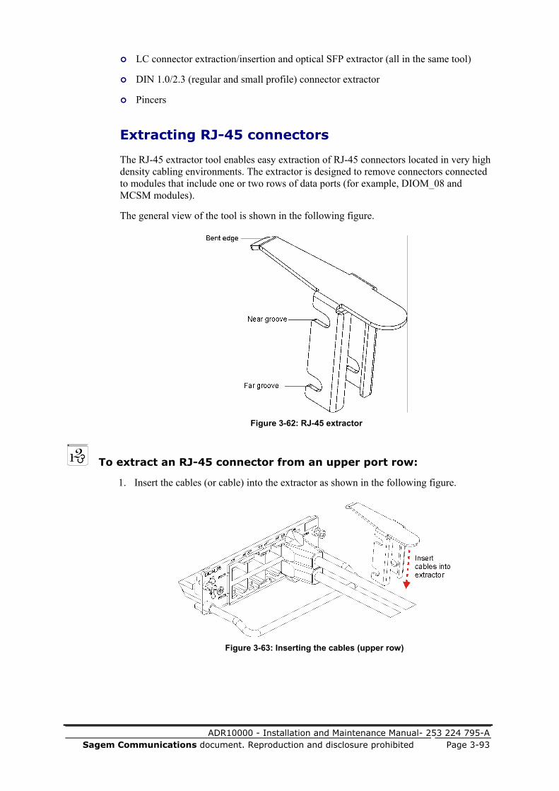
ADR10000 - Installation and Maintenance Manual- 253 224 795-A Sagem Communications document. Reproduction and disclosure prohibited Page 3-93
LC connector extraction/insertion and optical SFP extractor (all in the same tool)
DIN 1.0/2.3 (regular and small profile) connector extractor
Pincers
Extracting RJ-45 connectors
The RJ-45 extractor tool enables easy extraction of RJ-45 connectors located in very high density cabling environments. The extractor is designed to remove connectors connected to modules that include one or two rows of data ports (for example, DIOM_08 and MCSM modules).
The general view of the tool is shown in the following figure.
Figure 3-62: RJ-45 extractor
To extract an RJ-45 connector from an upper port row:
1. Insert the cables (or cable) into the extractor as shown in the following figure.
Figure 3-63: Inserting the cables (upper row)

ADR10000 - Installation and Maintenance Manual- 253 224 795-A
Page 3-94 Sagem Communications document. Reproduction and disclosure prohibited
2. Move extractor forward to attach the far groove to the module's handle.
Figure 3-64: Attaching the extractor to the handle (upper row)
3. Press the extractor's bent edge on the connector's protrusion.
4. Hold the cable near the connector to be extracted and pull the connector out.
Figure 3-65: Extracting the connector (upper row)

ADR10000 - Installation and Maintenance Manual- 253 224 795-A Sagem Communications document. Reproduction and disclosure prohibited Page 3-95
To extract an RJ-45 connector from a lower port row:
1. Insert the cables (or cable) into the extractor as shown in the following figure.
Figure 3-66: Inserting the cables (lower row)
2. Move extractor forward to attach the near groove to the module's handle.
Figure 3-67: Attaching the extractor to the handle (lower row)
3. Press the extractor's bent edge on the connector's protrusion.

ADR10000 - Installation and Maintenance Manual- 253 224 795-A
Page 3-96 Sagem Communications document. Reproduction and disclosure prohibited
4. Hold the cable near the connector to be extracted and pull the connector out.
Figure 3-68: Extracting the connector (lower row)
Extracting/Inserting LC connectors and SFPs
The LC/SFP extractor is a multipurpose tool enabling the extraction/insertion of LC connectors connected in very high density cabling environments (for example, LC connectors cabled near multiple adjacent SFPs). The tool is also designed to extract SFP transceivers.
The following figure shows the LC/SFP extractor.
Figure 3-69: LC/SFP extractor
Before you start:
Identify the LC/SFP extractor according to LC/SFP extractor (on page 3-96).
Fold the SFP extractor lever into the tool's narrow end. Use the tool's wide end to perform the following procedure.

ADR10000 - Installation and Maintenance Manual- 253 224 795-A Sagem Communications document. Reproduction and disclosure prohibited Page 3-97
To extract an LC connector:
1. Insert the fiber near the boot under the extractor's wide end tab.
Figure 3-70: Inserting the fiber into the extractor
2. Push the extractor straight forward and press its release tab onto the SFP's clip, until it clicks over top of the clip.
Figure 3-71: Pressing extractor's release tab onto SFP's clip
3. Pull out the extractor with the fiber.
Figure 3-72: Extracting the LC connector

ADR10000 - Installation and Maintenance Manual- 253 224 795-A
Page 3-98 Sagem Communications document. Reproduction and disclosure prohibited
4. Move the fiber backward till its connector is beyond the extractor's tab.
Figure 3-73: Moving the connector beyond the tab
5. Remove the fiber from the extractor.
Figure 3-74: Removing the fiber
Before you start:
Identify the LC/SFP extractor according to LC/SFP extractor (on page 3-96).
Fold the SFP extractor lever into tool's wide end. Use the tool's narrow end to perform the following procedure.
To insert an LC connector:
1. Insert the fiber near its boot, under the extractor's narrow end tab. Orient connector's clip in front of the tool's teeth.
Figure 3-75: Inserting the fiber into extractor's narrow end

ADR10000 - Installation and Maintenance Manual- 253 224 795-A Sagem Communications document. Reproduction and disclosure prohibited Page 3-99
2. Push the extractor forward until stopped by the connector's clip.
Figure 3-76: Moving extractor's end to the connector
3. Insert the connector into the SFP until it locks.
Figure 3-77: Inserting the connector into the SFP
4. Gently pull the extractor back until its edge is beyond the boot.
Figure 3-78: Moving the extractor backward
5. Remove the extractor from the fiber near the boot.
Figure 3-79: Removing the extractor from the fiber

ADR10000 - Installation and Maintenance Manual- 253 224 795-A
Page 3-100 Sagem Communications document. Reproduction and disclosure prohibited
Before you start:
Identify the LC/SFP extractor according to LC/SFP extractor (on page 3-96).
Fold the SFP extractor lever into the tool's narrow end. Use the tool's narrow side to perform the following procedure.
To extract an SFP transceiver:
1. Orient the extractor in front of the SFP.
Figure 3-80: Orienting the extractor in front of the SFP
2. Push the extractor forward until stopped by the SFP.
Figure 3-81: Moving the extractor forward
3. Push the extractor forward to fit SFP's middle partition into extractor's edge slot.
Figure 3-82: Fitting SFP's partition into extractor's slot

ADR10000 - Installation and Maintenance Manual- 253 224 795-A Sagem Communications document. Reproduction and disclosure prohibited Page 3-101
4. Move the extractor's teeth to the right (toward the SFP clip).
Figure 3-83: Moving extractor toward SFP clip
5. Pull the extractor slightly backward. Make sure that the clip is grasped and moves with the tool.
Figure 3-84: Pulling the extractor backward with grasped clip
6. Slide the lever forward to lock the SFP's clip, and press slightly.
Figure 3-85: Locking the clip between lever and extractor's teeth

ADR10000 - Installation and Maintenance Manual- 253 224 795-A
Page 3-102 Sagem Communications document. Reproduction and disclosure prohibited
7. With the clip locked, pull the extractor backward to rotate the clip by` 90°, and release the SFP from its housing.
Figure 3-86: Releasing the SFP from housing
8. Gently pull the SFP and extract it from the housing.
Figure 3-87: Extracting the SFP
NOTE: It is very important to keep the SFPs locked during the last three steps of the procedure.

ADR10000 - Installation and Maintenance Manual- 253 224 795-A Sagem Communications document. Reproduction and disclosure prohibited Page 3-103
Extracting/Inserting DIN 1.0/2.3 coaxial connectors
The DIN 1.0/2.3 connector extractor tool enables the extraction/insertion of coaxial connectors connected in very high density cabling environments (for example, coaxial connectors cabled near multiple adjacent electrical SFPs).
The following figure identifies the DIN 1.0/2.3 connector extractor.
Figure 3-88: DIN 1.0/2.3 extractor
Before you start:
Identify the coaxial extractor according to DIN 1.0/2.3 extractor (on page 3-103).
Use the tool's narrow end to perform the following procedure.

ADR10000 - Installation and Maintenance Manual- 253 224 795-A
Page 3-104 Sagem Communications document. Reproduction and disclosure prohibited
To extract a DIN1.0/2.3 connector:
1. Place the extractor on the coaxial cable in front of the connector.
Figure 3-89: Placing the extractor in front of the connector
2. Push the extractor forward and attach the end tabs on the connector's step.
Figure 3-90: Attaching the extractor to the connector's step

ADR10000 - Installation and Maintenance Manual- 253 224 795-A Sagem Communications document. Reproduction and disclosure prohibited Page 3-105
3. Pull the extractor with the connector backward and release the connector.
Figure 3-91: Extracting the connector
Before you start:
Identify the coaxial extractor according to DIN 1.0/2.3 extractor (on page 3-103).
Use the tool's wide end to perform the following procedure.
To insert a DIN 1.0/2.3 connector:
1. Insert the coaxial cable near its boot, under the extractor's wide end tab.
Figure 3-92: Inserting the coaxial cable into the extractor

ADR10000 - Installation and Maintenance Manual- 253 224 795-A
Page 3-106 Sagem Communications document. Reproduction and disclosure prohibited
2. Pull the cable backward until the connector 's edge is stopped by the tab.
Figure 3-93: Positioning the connector in the extractor
3. Push the extractor with the connector forward until it clicks into the SFP.
Figure 3-94: Inserting the connector

ADR10000 - Installation and Maintenance Manual- 253 224 795-A Sagem Communications document. Reproduction and disclosure prohibited Page 3-107
4. Gently pull the extractor backward and release it from the cable.
Figure 3-95: Removing the extractor
Attaching TPUs/OCU to the ADR-10000 Shelf
The ADR-10000 shelf can be expanded with one or two TPU expansion shelves.
The TPU can be attached on top of the ADR-10000 and/or directly under it. Alternatively, a single OCU expansion shelf can be attached directly on top of the ADR-10000 or on top of a TPU that is installed on the ADR-10000.
NOTE: The OCU cannot be installed under the ADR-10000 shelf.
When you order an ADR-10000 system with one or two TPUs, the shelf is supplied with the TPUs installed and their fastening brackets attached to each one. The same applies to OCU shelves.
If your ADR-10000 shelf does not include TPU protection, it is possible to upgrade your system and add one or two TPUs and an OCU at a later stage, provided you have left space on the rack for this possibility. You need at least 150 mm space above/under the ADR-10000 for each TPU/OCU.
The TPUs can be installed without disconnecting any of the ADR-10000 cables and fibers and without affecting traffic not going via a TPU.
CAUTION: This procedure should be carried out only by an SAGEM Communications trained field engineer.

ADR10000 - Installation and Maintenance Manual- 253 224 795-A
Page 3-108 Sagem Communications document. Reproduction and disclosure prohibited
Installing a TPU/OCU on the ADR-10000 shelf
The following section describes the procedure for installing a TPU/OCU on top of an ADR-10000 shelf.
To install a TPU on top of the ADR-10000 shelf:
1. Check that the TPU has not been physically damaged during shipment, and that the antistatic protection bag of the original packaging is sealed.
2. Remove the shelf from its antistatic protection packaging and perform a visual inspection to detect damage during shipping. Report any problems.
3. Record the hardware and software versions indicated on the shelf’s identification labels.
4. Arrange all cables and fibers leading to the ADR-10000 so that they will not unintentionally be disconnected when the TPU is inserted on the rack.
5. Open the two screws securing the protective cover of the TPU connector in place (located at the back right corner, on the top of the ADR-10000 shelf). Remove the cover.
Figure 3-96: Removing the TPU connector from the ADR-10000
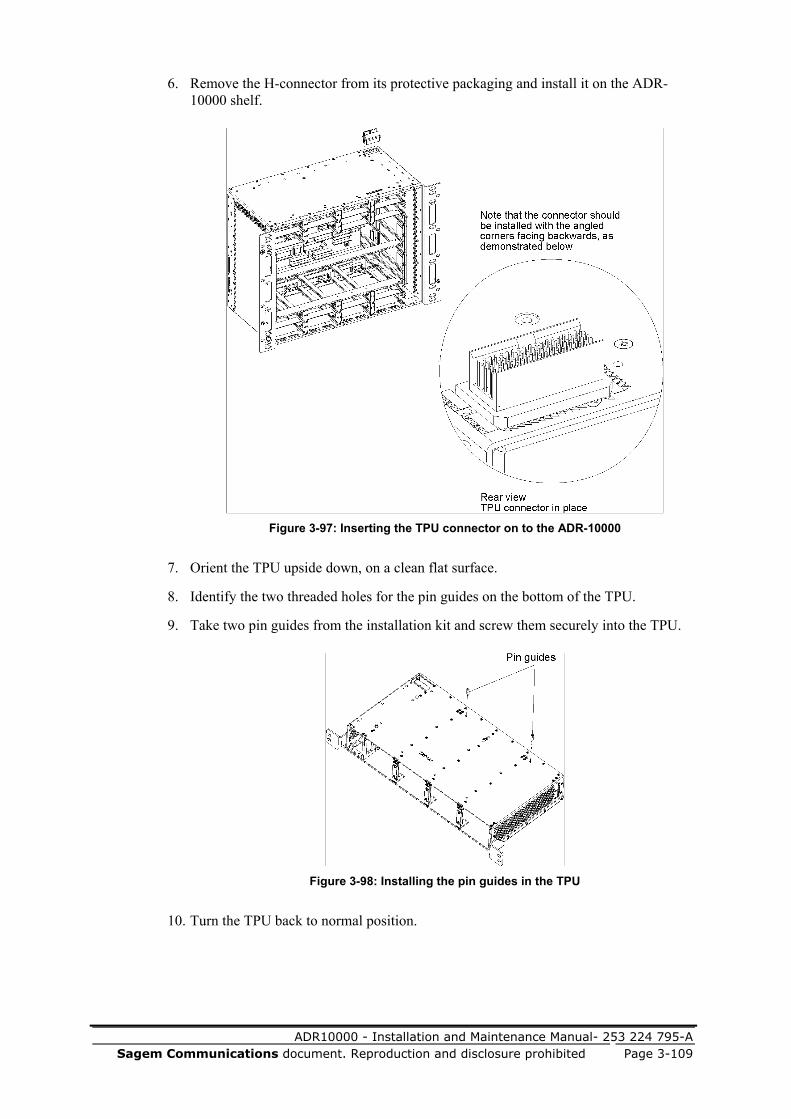
ADR10000 - Installation and Maintenance Manual- 253 224 795-A Sagem Communications document. Reproduction and disclosure prohibited Page 3-109
6. Remove the H-connector from its protective packaging and install it on the ADR-10000 shelf.
Figure 3-97: Inserting the TPU connector on to the ADR-10000
7. Orient the TPU upside down, on a clean flat surface.
8. Identify the two threaded holes for the pin guides on the bottom of the TPU.
9. Take two pin guides from the installation kit and screw them securely into the TPU.
Figure 3-98: Installing the pin guides in the TPU
10. Turn the TPU back to normal position.
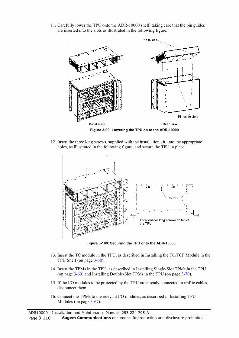
ADR10000 - Installation and Maintenance Manual- 253 224 795-A
Page 3-110 Sagem Communications document. Reproduction and disclosure prohibited
11. Carefully lower the TPU onto the ADR-10000 shelf, taking care that the pin guides are inserted into the slots as illustrated in the following figure.
Figure 3-99: Lowering the TPU on to the ADR-10000
12. Insert the three long screws, supplied with the installation kit, into the appropriate holes, as illustrated in the following figure, and secure the TPU in place.
Figure 3-100: Securing the TPU onto the ADR-10000
13. Insert the TC module in the TPU, as described in Installing the TC/TCF Module in the TPU Shelf (on page 3-68).
14. Insert the TPMs in the TPU, as described in Installing Single-Slot TPMs in the TPU (on page 3-69) and Installing Double-Slot TPMs in the TPU (on page 3-70).
15. If the I/O modules to be protected by the TPU are already connected to traffic cables, disconnect them.
16. Connect the TPMs to the relevant I/O modules, as described in Installing TPU Modules (on page 3-67).

ADR10000 - Installation and Maintenance Manual- 253 224 795-A Sagem Communications document. Reproduction and disclosure prohibited Page 3-111
CAUTION: Insert/extract the TPU in/from an ADR-10000 only when it is empty (no TC/TCF or TPMs are assembled in it).
Installing a TPU under the ADR-10000 Shelf
The following section describes the procedure for installing a TPU under an ADR-10000 shelf.
To install a TPU under the ADR-10000 shelf:
1. Check that the TPU has not been physically damaged during shipment, and that the antistatic protection bag of the original packaging is sealed.
2. Remove the shelf from its antistatic protection packaging and perform a visual inspection to detect damage during shipping. Report any problems.
3. Record the hardware and software versions indicated on the shelf’s identification labels.
4. Arrange all cables and fibers leading to the ADR-10000 so that they will not unintentionally be disconnected when the TPU is inserted on the rack.
5. Turn the ADR-10000 shelf so that its rear faces the front.
6. Lift the ADR-10000 on its far lower edge to gain access to the bottom surface, as shown in the following figure.
Figure 3-101: Installing the ADR-10000 pin guides and removing the lower connector
cover
7. Open the two captive screws fastening the lower TPU connector cover to the shelf. Remove the cover.
8. Identify the two threaded holes for the pin guides at the bottom of the shelf (see the figure above).
ADR-10000bottom

ADR10000 - Installation and Maintenance Manual- 253 224 795-A
Page 3-112 Sagem Communications document. Reproduction and disclosure prohibited
9. Take two pin guides from the installation kit and screw them securely in place.
10. Remove the H-connector from its protective packaging and install it on the ADR-10000 shelf (see installation of the H-connector in Inserting the TPU connector onto the ADR-10000 (on page 3-109)). Note that the connector should be installed with the angled corner facing backwards.
11. Open the two screws securing the TPU connector cover (located at the back right corner, on top of the TPU). Remove the cover.
12. Open the six screws securing the fastening bracket to the TPU shelf (keep the screws handy). Remove the bracket.
13. Orient the TPU on a clean flat surface, upside down.
14. Place the TPU's fastening bracket (removed in step 12) on the TPU and attach it with the six screws.
Figure 3-102: Assembling the TPU bracket and jumper connector
15. Open the two captive screws fastening the second connector cover to the TPU. Remove the cover.
16. Take the jumper connector from the installation kit and insert it into the connector house.
17. Fasten the jumper connector in place with three screws from the installation kit.
18. Turn the TPU back to regular position.

ADR10000 - Installation and Maintenance Manual- 253 224 795-A Sagem Communications document. Reproduction and disclosure prohibited Page 3-113
19. Carefully lower the ADR-10000 shelf onto the TPU, taking care that the pin guides are inserted into the slots, as illustrated in the following figure.
Figure 3-103: Lowering the ADR-10000 onto the TPU
20. Insert the three long screws supplied in the installation kit into the appropriate holes, as illustrated in the following figure, and secure the TPU in place.
Figure 3-104: Securing the lower TPU to the shelf
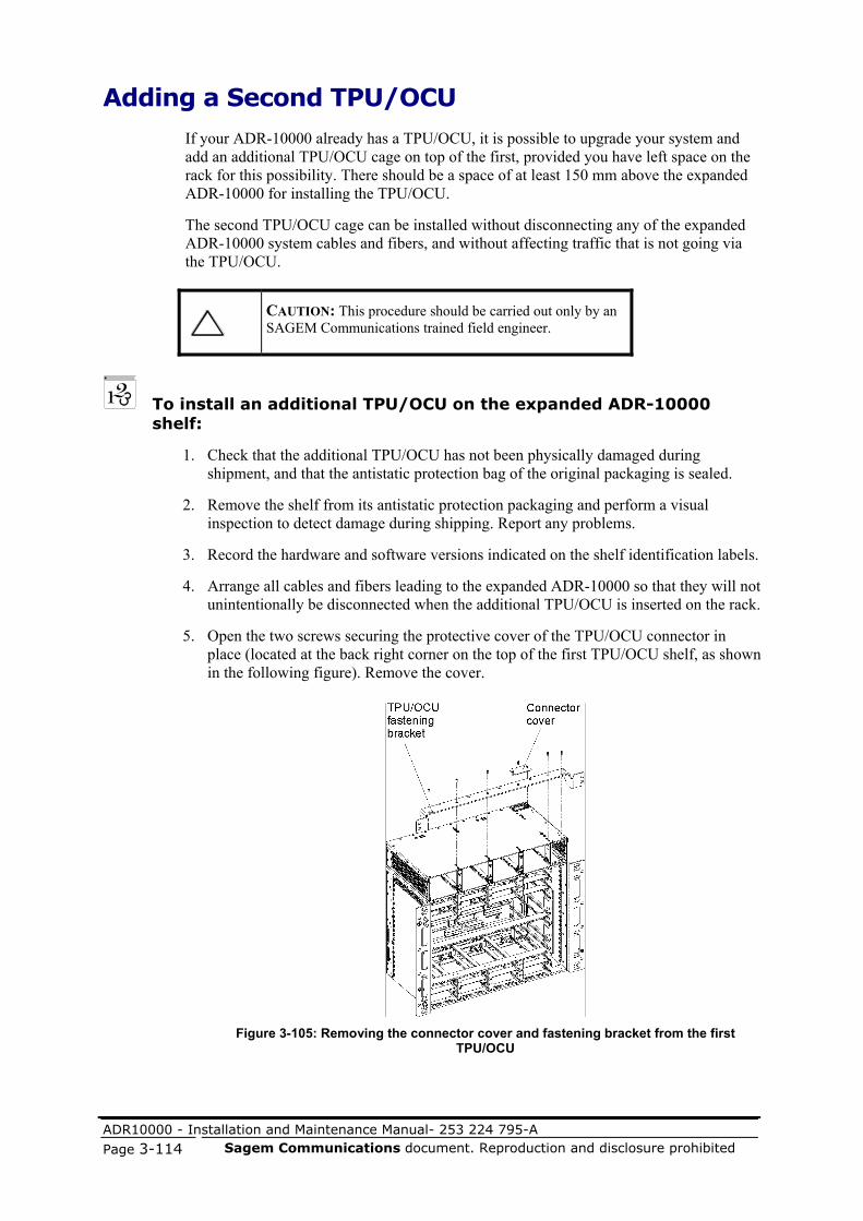
ADR10000 - Installation and Maintenance Manual- 253 224 795-A
Page 3-114 Sagem Communications document. Reproduction and disclosure prohibited
Adding a Second TPU/OCU
If your ADR-10000 already has a TPU/OCU, it is possible to upgrade your system and add an additional TPU/OCU cage on top of the first, provided you have left space on the rack for this possibility. There should be a space of at least 150 mm above the expanded ADR-10000 for installing the TPU/OCU.
The second TPU/OCU cage can be installed without disconnecting any of the expanded ADR-10000 system cables and fibers, and without affecting traffic that is not going via the TPU/OCU.
CAUTION: This procedure should be carried out only by an SAGEM Communications trained field engineer.
To install an additional TPU/OCU on the expanded ADR-10000 shelf:
1. Check that the additional TPU/OCU has not been physically damaged during shipment, and that the antistatic protection bag of the original packaging is sealed.
2. Remove the shelf from its antistatic protection packaging and perform a visual inspection to detect damage during shipping. Report any problems.
3. Record the hardware and software versions indicated on the shelf identification labels.
4. Arrange all cables and fibers leading to the expanded ADR-10000 so that they will not unintentionally be disconnected when the additional TPU/OCU is inserted on the rack.
5. Open the two screws securing the protective cover of the TPU/OCU connector in place (located at the back right corner on the top of the first TPU/OCU shelf, as shown in the following figure). Remove the cover.
Figure 3-105: Removing the connector cover and fastening bracket from the first
TPU/OCU

ADR10000 - Installation and Maintenance Manual- 253 224 795-A Sagem Communications document. Reproduction and disclosure prohibited Page 3-115
6. Open the six screws securing the fastening bracket to the first TPU/OCU shelf installed on the expanded ADR-10000 (see the previous figure).
7. Open the two screws fastening the bracket to the rack. Remove the bracket.
8. Orient the second TPU upside down, on a clean flat surface.
9. Identify the two threaded holes for the pin guides on the bottom of the second TPU.
10. Take two pin guides from the installation kit and screw them securely into the TPU.
Figure 3-106: Installing the pin guides in the TPU
11. Remove the H-connector from its protective packaging and install it on the first TPU/OCU shelf, as shown in the following figure.
Figure 3-107: Inserting the TPU/OCU connector on to the first TPU/OCU in the ADR-10000

ADR10000 - Installation and Maintenance Manual- 253 224 795-A
Page 3-116 Sagem Communications document. Reproduction and disclosure prohibited
12. Carefully lower the second TPU/OCU onto the expanded ADR-10000 (on the first TPU/OCU shelf), taking care that the pin guides are inserted into the slots as illustrated in the following figure.
Figure 3-108: Lowering the second TPU/OCU on to the expanded ADR-10000.
13. Insert the three long screws supplied in the installation kit into the appropriate holes, as illustrated in the following figure, and secure the second TPU/OCU in place.
Figure 3-109: Securing the second TPU/OCU on to the expanded ADR-10000
ExpandedADR-10000

ADR10000 - Installation and Maintenance Manual- 253 224 795-A Sagem Communications document. Reproduction and disclosure prohibited Page 4-1
In this chapter: Overview..........................................................................................................4-1 Required Test Equipment, Tools, and Materials .............................................4-1 Preventive Maintenance...................................................................................4-1 Traffic Monitoring System ..............................................................................4-3 Onsite Troubleshooting....................................................................................4-7 Replacing Cards and Modules .......................................................................4-14 Replacing RAP Components .........................................................................4-19
Overview This chapter provides maintenance procedures for ADR-10000 equipment.
Required Test Equipment, Tools, and Materials
For most maintenance activities described in this chapter, only a Craft terminal and a multimeter are required. If you need to make measurements, it is recommended to use equipment of the same type and models used for commissioning tests. The tools and materials necessary for equipment installation must also be available during maintenance.
Preventive Maintenance The purpose of the preventive maintenance activities is to keep the ADR-10000 hardware in good condition, and detect and correct as soon as possible any condition that may lead to deterioration and equipment malfunction.
4 Maintenance
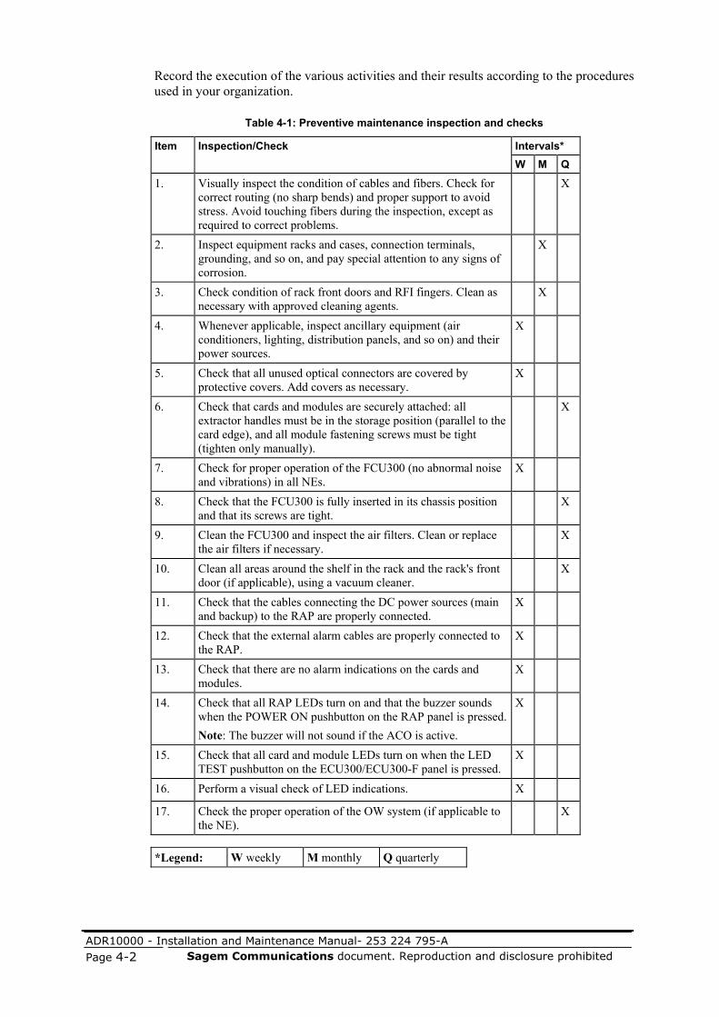
ADR10000 - Installation and Maintenance Manual- 253 224 795-A
Page 4-2 Sagem Communications document. Reproduction and disclosure prohibited
Record the execution of the various activities and their results according to the procedures used in your organization.
Table 4-1: Preventive maintenance inspection and checks
Intervals* Item Inspection/Check W M Q
1. Visually inspect the condition of cables and fibers. Check for correct routing (no sharp bends) and proper support to avoid stress. Avoid touching fibers during the inspection, except as required to correct problems.
X
2. Inspect equipment racks and cases, connection terminals, grounding, and so on, and pay special attention to any signs of corrosion.
X
3. Check condition of rack front doors and RFI fingers. Clean as necessary with approved cleaning agents.
X
4. Whenever applicable, inspect ancillary equipment (air conditioners, lighting, distribution panels, and so on) and their power sources.
X
5. Check that all unused optical connectors are covered by protective covers. Add covers as necessary.
X
6. Check that cards and modules are securely attached: all extractor handles must be in the storage position (parallel to the card edge), and all module fastening screws must be tight (tighten only manually).
X
7. Check for proper operation of the FCU300 (no abnormal noise and vibrations) in all NEs.
X
8. Check that the FCU300 is fully inserted in its chassis position and that its screws are tight.
X
9. Clean the FCU300 and inspect the air filters. Clean or replace the air filters if necessary.
X
10. Clean all areas around the shelf in the rack and the rack's front door (if applicable), using a vacuum cleaner.
X
11. Check that the cables connecting the DC power sources (main and backup) to the RAP are properly connected.
X
12. Check that the external alarm cables are properly connected to the RAP.
X
13. Check that there are no alarm indications on the cards and modules.
X
14. Check that all RAP LEDs turn on and that the buzzer sounds when the POWER ON pushbutton on the RAP panel is pressed.Note: The buzzer will not sound if the ACO is active.
X
15. Check that all card and module LEDs turn on when the LED TEST pushbutton on the ECU300/ECU300-F panel is pressed.
X
16. Perform a visual check of LED indications. X
17. Check the proper operation of the OW system (if applicable to the NE).
X
*Legend: W weekly M monthly Q quarterly

ADR10000 - Installation and Maintenance Manual- 253 224 795-A Sagem Communications document. Reproduction and disclosure prohibited Page 4-3
Recommended Cleaning Methods
The following methods (listed in order of ascending efficiency) can be used to clean air filters:
1. Vacuum clean: A few passes of a vacuum cleaner remove accumulated dust and dirt in seconds. Point the air nozzle in the direction of operating airflow (vacuum from intake side toward exhaust side).
2. Blow with compressed air: Point a compressed air nozzle in the opposite direction of the operating airflow (blow from the exhaust side toward the intake side).
NOTE: Oily residues and moisture reduce cleaning efficiency of the above methods; in such cases, clean the filter using method No. 4, or replace the filter.
3. Cold water rinse: Under normal service conditions, the foam media used in the filters require no oily adhesives. Therefore, collected dust and dirt can be washed away using a standard hose nozzle with plain water. Stand the filter until completely dry and free of moisture, and return to service.
4. Immersion in warm soapy water: Where stubborn airborne dirt is present, the filter may be dipped in a solution of warm water and mild detergent. Then simply rinse in clear water, stand until completely dry and free of moisture, and return to service.
The recommended method is No. 4, as it ensures thorough cleaning of all types of contaminants under any reasonable service conditions.
Traffic Monitoring System
Principles of Operation
The ADR-10000 incorporates a traffic monitoring system that enables rapid allocation of major problems in the traffic passing through its aggregate and I/O modules.
The ADR-10000 monitoring system enables you to monitor traffic passing through the I/O modules installed in slots I1 to I16 of the modules cages.
NOTE: I/O CWDM modules installed in the modules cage slots are not supported by the monitoring system.

ADR10000 - Installation and Maintenance Manual- 253 224 795-A
Page 4-4 Sagem Communications document. Reproduction and disclosure prohibited
The main components of the monitoring system interface are located on the ECU300-F front panel. These components, except for the monitoring point and monitoring indicator, are common to all modules. In addition, the system has a monitoring point and monitoring indicators on the front panel of the modules. The PIM2_63/B and PIM345 have only one monitoring indicator used for all their channels. STM-1 modules do not have a monitoring point, and use the monitoring point on the ECU300-F card.
Figure 4-1: ECU300-F monitoring system interface.
The system's common components on the ECU300-F are as follows:
MODULE selector
CHANNEL selector
MODULE, 2-digit display
CHANNEL, 2-digit display
The ECU300-F components that serve only STM-1 modules are:
STM-1 MON monitoring point
MON indicator
The monitoring system components on the monitored modules include:
MON monitoring point
MON indicators
Figure 4-2: Monitoring system interface of a typical module.

ADR10000 - Installation and Maintenance Manual- 253 224 795-A Sagem Communications document. Reproduction and disclosure prohibited Page 4-5
The monitoring system enables you to monitor traffic passing through a module. To do so, test equipment is connected to the monitoring point of the corresponding module, and the module and port are selected by the system's selectors. As a result, the traffic is closed through the test equipment and the signal can be viewed, in an eye pattern, on the test equipment display.
Selecting a module
The MODULE selector chooses the monitored module slot number. The selected module is displayed on the 2-digit display to the right of the selector. Pressing the selector upward increments the slot number; pressing it downward decrements the slot number. The selection is cyclic. Possible selections are QA (I17) and QB (I18) for the aggregate cards (I/O cards), and I1 to I16 for the I/O modules. If the selected module is an STM-1, the MON indicator on the ECU300-F lights.
Selecting a channel
The CHANNEL selector chooses the specific monitored channel (port) on the module selected. The selected channel is displayed on the 2-digit display to the left of the selector. Pressing the selector upward increments the channel number; pressing it downward decrements the channel number. The selection is cyclic. Possible selections are from 00 to the module's maximum number of channels. For example, in a PIM2_21 (which has 21 ports), the selection goes from 00 to 21. When the value 00 is selected, the system blocks the monitoring to the selected module.
In addition to the number of the selected channel shown on the display, a MON indicator lights near the selected port on the module. If an STM-1 module is selected, the MON indicator on the ECU300-F lights in addition to the LED near the selected port on the module.
Stabilization time
The monitoring system has a stabilization time of approximately 1.5 seconds. This means that after a new value is selected with the MODULE or CHANNEL selectors, the display starts blinking for the stabilization time, and only after that the new selection is displayed.
Response to events
This section describes the response of the monitoring system to the following events:
Power-on
Cold restart
MXC300 switching to redundancy
Warm restart
ECU300-F extraction/insertion
After power-on, the monitoring system displays 17 00. This is the default state, and indicates slot I17 and channel 00. Channel 00 is defined in the system as idle state, and indicates that no channel was selected and that monitoring is disabled. To enable the monitoring results, a module and a channel must be selected.

ADR10000 - Installation and Maintenance Manual- 253 224 795-A
Page 4-6 Sagem Communications document. Reproduction and disclosure prohibited
The response of the system to MXC300 switching to redundancy is identical to the response to cold restart.
Warm restart does not affect the traffic or monitoring of any modules in the ADR-10000.
After extracting/inserting the ECU300-F, the monitoring display is reset to the default state 17 00, and the monitoring history stored in the ECU300-F's memory is lost.
Assigning modules to slots
To monitor a module installed in a specific slot, the management system must have previously assigned that module to the slot. If the module was not assigned, the CHANNEL display will indicate 00 and remain in this state, even if you attempt to change the selection.
If a module in a slot is replaced with a module of the same type, the display will not change and the system will read the monitoring result for the channel that was last selected. If a module has to be replaced with a module of a different type, the new module must be assigned to the slot. Then, a new MODULE and CHANNEL selection must be made.
Monitoring options
The system can monitor a number of channels in different modules simultaneously. This feature is useful when traffic passing through different modules in the ADR-10000 has to be analyzed.
After monitoring channels of different modules, all selected channel numbers of these modules are saved in the ECU-F's memory.
You can connect test equipment to various modules or connect test equipment with multiple inputs to simultaneously monitor the traffic passing through the channels in these modules.
Monitoring Signal Levels
The following table lists the normal signal levels at the monitoring points for the various modules.
Table 4-2: I/O modules monitoring data
Module type Monitoring point Number of channels (ports)
Signal rate and level
SIM1_4/E ECU300-F front panel 4 155 Mbps, CMI SIM1_8 ECU300-F front panel 8 155 Mbps, CMI
SIM4_4 Module front panel 4 622 Mbps, NRZ PIM2_63/B Module front panel 63 2.048 Mbps, HDB-3 PIM345_3 Module front panel 3 34 or 45 Mbps, HDB-3

ADR10000 - Installation and Maintenance Manual- 253 224 795-A Sagem Communications document. Reproduction and disclosure prohibited Page 4-7
Monitoring Modules Traffic
Monitoring the traffic of STM-1 and other modules operating at a different rate is similar, and differs only in the location of the monitoring point and LED indicators.
To monitor the traffic in a non-STM-1 module:
1. Identify the slot number of the module to be monitored.
2. Connect the test equipment to the monitoring point.
3. Select the slot number of the monitored module using the MODULE selector.
4. Select the channel number of the monitored port using the CHANNEL selector.
5. Wait for the display to stabilize (stop blinking), and then verify that the required slot and channel were selected.
6. Verify that the MON indicator of the selected channel lights.
7. Read the test result on the test equipment connected to the monitoring point.
To monitor the traffic in an STM-1 module:
1. Identify the slot number of the module to be monitored.
2. Connect the test equipment to the monitoring point on the ECU300-F card.
3. Perform Steps 3 to 5 in the previous section.
4. Verify that the MON indicator on the ECU300-F card and the corresponding MON indicator on the STM-1 module light.
5. Read the test result on the test equipment connected to the monitoring point.
Onsite Troubleshooting The purpose of onsite troubleshooting is to identify the hardware causing the malfunction and return the equipment to normal operation as soon as possible.
Troubleshooting is usually initiated in response to one of the following conditions:
Alarm or performance degradation reported by the management station.
Alarm or malfunction detected on site by maintenance personnel, either as a result of a troubleshooting activity initiated by the management center personnel or as a result of a periodic inspection or preventive maintenance action. Many problems can be detected via the various indicators available on the ADR-10000 system components.
This chapter assumes familiarity with the ADR-10000, with SDH, data, and with the IONOS-NMS and EMS-ADR management stations. Refer to the respective user manuals for details on the various capabilities of the management stations, and for instructions on performing the desired activities.

ADR10000 - Installation and Maintenance Manual- 253 224 795-A
Page 4-8 Sagem Communications document. Reproduction and disclosure prohibited
The following sections provide procedures for performing on site trouble shooting for various trouble categories, as well as for specific subsystems, for example, OADMs, Mux/DeMux subsystems, and so on. For each category, you will find a troubleshooting table that provides the instructions for identifying the trouble.
To use the troubleshooting table:
1. Identify the closest description of the trouble symptoms under “Symptoms”.
2. Perform the required corrective actions listed under “Corrective actions” in the order in which they appear until the trouble is corrected.
Troubleshooting Power Problems
Table 4-3: Troubleshooting power problems
No. Symptoms Probable cause Corrective actions
Both main and backup power sources failed.
1. Check the site power distribution system.
2. Check the DC voltage at the main and backup power terminals of the RAP.
3. If the voltage is not within the correct range, check cable connections up to the DC power distribution panel, and make sure no fuses are blown.
4. Check the voltage supplied by the main and backup power sources.
5. Check the power connections to the RAP.
6. Check the circuit breakers in the RAP and replace if necessary.
1 RAP POWER ON indicator is off.
Equipment problem. 1. Check the voltage at the MXC300 end of each power cable. Replace the cable or repair the RAP if there is no voltage present.
2. If after checking (as explained above) and reconnecting a cable to the equipment, the circuit breaker trips again, replace the corresponding MXC300 card.
3. If the problem occurs again after Step 2, remove all the cards and modules from the shelf and reinsert them one by one until you find the component causing the circuit breaker to trip. Replace that component.
2 MXC300 ACTIVE indicator is off.
No input power to the corresponding unit.
1. Check the corresponding circuit breaker in the RAP; reset any tripped breaker.
2. Check the circuit breakers in the RAP and replace if necessary.
3. If the circuit breaker trips again, disconnect the cable protected by the corresponding circuit breaker from the equipment and check the voltage polarity.
4. Check the power cable condition and make sure that the cable is not damaged and does not cause short circuits.
5. Check proper cable connection at both ends.
3 MXC300 FAIL indicator lights.
Technical failure in the corresponding unit.
Replace the unit.

ADR10000 - Installation and Maintenance Manual- 253 224 795-A Sagem Communications document. Reproduction and disclosure prohibited Page 4-9
Troubleshooting Using Component Indicators
The management station will usually provide onsite personnel with a list of suspected components.
Start the troubleshooting of a suspected component by checking its indicators. These indicators, located on the various cards and modules, can help you to rapidly and efficiently identify a malfunctioning component in accordance with the procedures outlined in the following tables.
CAUTION: The following corrective actions are traffic-affecting.
Table 4-4: General troubleshooting procedures for cards/modules
No. Symptoms Probable cause Corrective actions
Defective indicator Press the LED TEST pushbutton on the ECU300/ECU300-F, and check that the indicator lights. If not, replace the card/module.
1 Green ACT/AC indicator is off. Defective
card/module 1. Remove the card/module and wait a minute before
reinserting it. Make sure that you fully insert the card or module in its slot.
2. If the ACT/AC indicator does not turn on after reinsertion, replace the card/module.
2 Red FAIL/FL indicator does not turn off after software download (this occurs after power-on and resetting).
Defective card/module
1. Remove the card/module and wait a few minutes before reinserting it. Make sure the ACT/AC indicator turns on after the card/module is reinserted.
2. The FAIL/FL indicator must flash while software is downloaded to the card/module. Wait until the software download is complete and check that the FAIL/FL indicator turns off.
3. If the FAIL/FL indicator turns on again, replace the card/module.
3 Orange (traffic carrying) indicator is off when indicator is supported.
Card/module not configured to carry traffic
Check with the management station operator if the card/module has already been configured and provisioned; if not, ignore the state of the orange indicator.
CAUTION: Before checking fiber break problems using an OTDR (Optical Time-Domain Reflectometer), it is the user's responsibility to disconnect the receiver port. Failure to do so may damage the receiver irreparably.

ADR10000 - Installation and Maintenance Manual- 253 224 795-A
Page 4-10 Sagem Communications document. Reproduction and disclosure prohibited
Table 4-5: General troubleshooting procedures for optical transceiver plug-ins
No. Symptoms Probable cause Corrective actions
1 Green transceiver state indicator is off.
The corresponding optical transmitter may have been turned off by the ALS function (see note below).
1. When available, press the laser-on pushbutton of the ECU300/ECU300-F to activate the corresponding laser.
2. If the problem persists, the laser automatically turns off again after a few seconds. Check that all the fibers are properly connected to the corresponding optical transceiver.
3. Replace the transceiver if the problem is not corrected after the transceiver is reinserted.
Test equipment is connected to the monitoring connector of the corresponding plug-in.
1. For plug-in transceivers with monitoring connector: the test equipment is connected to the monitoring connector. This indication is provided for identification purposes, and does not necessarily indicate a malfunction.
2 Transceiver state indicator lights in red.
Defective transceiver.
1. Disconnect the fibers connected to the transceiver and remove it.
2. Reinstall the transceiver in its position, making sure to fully engage its connector to the mating card connector.
3. Replace the transceiver if the problem is not corrected after the transceiver is reinserted.
Table 4-6: Troubleshooting procedures for electrical interface modules
NOTE: An optical port with ALS capability turns off its transmitter when the corresponding receive signal is lost. Turning the transmitter off may cause a chain reaction, which turns the optical signals off in a whole section of the network and generates a large number of alarms.
As a result, it may be difficult to identify the real cause of the problem, and you may need to use the management station log records to identify the port.
No. Symptoms Probable cause Corrective actions
Defective indicator Press the LED TEST pushbutton on the ECU300/ECU300-F and check that the indicator lights. If not, replace the card/module.
1 Green AC indicator is off.
Defective module 1. Remove the module and wait a minute before reinserting it. Make sure that you fully insert the module in its slot.
2. If the AC indicator does not turn on after reinsertion, replace the module.
2 Red FL indicator does not turn off after software download (this occurs after power-on and resetting).
Defective module 1. Remove the module and wait a few minutes before reinserting it to reset. Make sure the AC indicator turns on after the module is reinserted.
2. The FL indicator must flash while software is downloaded to the module. Wait until the software download ends and check that the FL indicator turns off.
3. If the FL indicator turns on again, replace the module.

ADR10000 - Installation and Maintenance Manual- 253 224 795-A Sagem Communications document. Reproduction and disclosure prohibited Page 4-11
Table 4-7: Troubleshooting procedures for optical OADM and Mux/DeMux
Table 4-8: Troubleshooting procedures for EISMs
No. Symptoms Probable cause Corrective actions
1 Green AC indicator is off.
Defective module 1. Remove the module and wait a minute before reinserting it. Make sure that you fully insert the module in its slot.
2. If the AC indicator does not turn on after reinsertion, replace the module.
2 Red FL indicator does not turn off after software download (this occurs after power-on and resetting).
Defective module 1. Remove the module and wait a few minutes before reinserting it to reset. Make sure the AC indicator turns on after the module is reinserted.
2. The FL indicator must flash while software is downloaded to the component. Wait until the software download ends and check that the FL indicator turns off.
3. If the FL indicator turns on again, replace the module.
No. Symptoms Probable cause Corrective actions
1 Green AC indicator is off.
Defective module 1. Remove the module and wait a minute before reinserting it. Make sure that you fully insert the card in its slot.
2. If the AC indicator does not turn on after reinsertion, replace the module.
2 Red FL indicator on the module does not turn off after software download (this occurs after power-on and resetting).
Defective module 1. Remove the module and wait a few minutes before reinserting it to reset. Make sure the AC indicator turns on after the module is reinserted.
2. The FL indicator must flash while software is downloaded to the module. Wait until the software download ends and check that the FL indicator turns off.
3. If the FL indicator turns on again, replace the module.
3 Orange (traffic carrying) indicator on module is off.
Module not configured to carry traffic
Check with the management station operator whether the module has already been configured and provisioned; if not, ignore the state of the orange indicator.
4 Green (link state) indicator of an Ethernet optical port is off.
Problem related to port
1. Check port configuration.
2. Check connections to LAN.
3. Make sure at least one LAN station is active.
4. Replace optical transceiver of port.
5 Link state indicator of an 10/100BaseT Ethernet port is off.
Problem related to port
1. Check port configuration.
2. Check connections to LAN.
3. Make sure at least one LAN station is active.

ADR10000 - Installation and Maintenance Manual- 253 224 795-A
Page 4-12 Sagem Communications document. Reproduction and disclosure prohibited
Troubleshooting the Timing Subsystem
Table 4-9: Troubleshooting procedures for timing subsystem
No. Symptoms Probable cause Corrective actions
Technical failure Force switching of traffic to the other MXC300, and then replace the MXC300 card with the defective TMU.
Missing T3/BITS IN external reference signal
1. Check the equipment providing the external reference signal and make sure it operates normally.
2. Check the cable connected to the corresponding ECU300/ECU300-F connector. Make sure both its ends are properly connected to the mating connector.
3. Check the cable wiring. Replace the cable if in doubt.
4. Replace the corresponding ECU300/ECU300-F.
Missing T4/BITS OUT external reference signal
1. Check the cable connected to the corresponding ECU300/ECU300-F connector. Make sure both its ends are properly connected to the mating connector.
2. Check the cable wiring. Replace the cable if in doubt.
3. Replace the corresponding ECU300/ECU300-F.
4. Force switching of traffic to the other MXC300, and then replace the MXC300 with the defective TMU.
1 Switching to standby TMU
Loss of reference clock source provided by a tributary
Troubleshoot the corresponding module and replace it if found faulty.
Troubleshooting Transmission and Traffic Alarms
Before any other troubleshooting activity, check the management station log to check if a specific component has been reported as faulty and replace it.
CAUTION: Before checking fiber break problems using an OTDR (Optical Time-Domain Reflectometer), it is the user's responsibility to disconnect the receiver port. Failure to do so may damage the receiver irreparably.
Table 4-10: Troubleshooting transmission and traffic alarms
No. Symptoms Probable cause Corrective actions
1 Alarm related to a client signal
External problem 1. Check the proper operation of the equipment providing the tributary signal and its connections to the ADR-10000 I/O port.
2. Use the results of the commissioning tests as a reference for the required signal levels, and make measurements of current levels at all the relevant monitoring points. Compare the reference levels with the measured values; a significant discrepancy may point to the failed component (for example, low transmit level, excessive fiber attenuation due to physical damage, and so on).

ADR10000 - Installation and Maintenance Manual- 253 224 795-A Sagem Communications document. Reproduction and disclosure prohibited Page 4-13
No. Symptoms Probable cause Corrective actions
2 Alarm related to a line signal
External problem 1. Check the proper operation of the equipment providing the line signal and its connections to the ADR-10000 port.
2. Use the network and site documentation to identify the path associated with the reported alarm and all related optical and/or electrical components. Use the results of the commissioning tests as a reference for the required signal levels, and make measurements of current levels at all the relevant monitoring points through the management.
3. Compare the reference levels with the measured values; a significant discrepancy may point to the failed component (for example, low transmit level, excessive fiber attenuation due to physical damage, and so on).
Troubleshooting Management Communication
When the management station cannot manage an ADR-10000 shelf, use the following table to identify the cause of the problem.
NOTE: Whenever you detect problems during commissioning tests and when troubleshooting a new installation, do not overlook the possibility of configuration and/or provisioning errors. Under such circumstances, always start the troubleshooting procedures by reviewing all equipment configuration and provisioning parameters against the original network design, and correct as necessary.
Table 4-11: Troubleshooting management communication
No. Symptoms Probable cause
Corrective actions
Defective card/module in management traffic path
1. Check for fault indications on the cards processing the management communication (see General troubleshooting procedures for cards/modules (on page 4-9)).
2. Force switching to the protection path and reset each component. Use the results of the BIT test to identify the faulty component.
Problem in transmission path
1. Use the network and site documentation to identify the path of the management communication to the corresponding ADR shelf and all the related optical components.
2. Use the results of the commissioning tests as a reference for the required signal levels, and make measurements of current levels at all the relevant monitoring points through the management.
3. Compare the reference levels with the measured values; a significant discrepancy may point to the failed component (for example, low transmit level, excessive fiber attenuation due to physical damage, and so on).
1 Problems in management traffic path
Other problems
Replace suspected components in the following sequence:
1. Hubs and Ethernet cables used for management traffic
2. ECU300/ECU300-F
3. MXC300

ADR10000 - Installation and Maintenance Manual- 253 224 795-A
Page 4-14 Sagem Communications document. Reproduction and disclosure prohibited
Replacing Cards and Modules
Safety and Workmanship
Refer to Before You Start for safety and workmanship instructions.
CAUTION: Static Sensitive Devices
PROPER HANDLING AND GROUNDING PRECAUTIONS REQUIRED
ADR-10000 equipment contains components sensitive to electrostatic discharge (ESD). To prevent ESD damage, strictly observe all the precautions listed in Protection against ESD. Keep parts and cards in their antistatic packaging material until you are ready to install them.
Use an antistatic wrist strap connected to a grounded equipment frame or rack when handling cards and modules during installation, removal, or connection to internal connectors.
Before you start:
When inserting cards and modules, make sure to carefully align the card or module with the shelf guide rails. If you feel resistance during insertion, immediately retract the card/module and then repeat the process.
Hold the card/module straight during insertion and removal, and pull or push it slowly and carefully to avoid touching components located on adjacent cards/modules.
Do not use excessive torque when tightening the fastening screws of cards and modules.
Visually inspect the card and the mating backplane connectors and make sure that there are no signs of physical damage. In particular, check for bent connector pins.
Before replacing any card, module, NVM, or optical transceiver:
1. Check that the replacement component has not been physically damaged during shipment.
2. Remove the replacement component from its antistatic protection packaging, and perform a visual inspection to detect damage during shipment. Report any problems.
3. Record the hardware and software versions as indicated on the component identification labels, and make sure they are compatible with those of the component to be replaced.
After replacing a component:
1. Place it in its antistatic protection packaging and close it.
2. Attach a report to the package explaining the reason for the replacement, and identify the network site, physical location, shelf, and time of replacement.

ADR10000 - Installation and Maintenance Manual- 253 224 795-A Sagem Communications document. Reproduction and disclosure prohibited Page 4-15
Replacing MXC300 Cards
This section provides replacement instructions for the MXC300.
CAUTION:
Do not extract/insert an MXC300 while the DC cables are connected to it.
If the FAIL (red), MAIN (blue), and TMU (orange) LEDs blink simultaneously, the MXC300 is not mounted correctly or not all four screws are properly locked.
Before attempting to remove the card, monitor its NVM (yellow) indicator; remove the card only after this indicator has been off for at least 2 minutes.
To replace the MXC300:
1. Initiate a forced switching to the other MXC300.
2. Wait until the NVM (yellow) indicator of the MXC300 to be replaced turns off and remains off for at least 2 minutes, and then remove the NVM card as described in Replacing the NVM on MXC300 cards. It is recommended to wait until the yellow indicator of the other MXC300 card also turns off.
CAUTION: When replacing any MXC300 card, the upper left screw operates a microswitch. When this screw is open, it indicates to the ADR-10000 platform that the MXC300 is not installed. This screw must be opened first when replacing an MXC300 card.
3. Open the MXC300 upper left screw first, then the upper right screw, and then the two lower screws.
4. Hold both extractor handles and pull them simultaneously outward until the card is released from the backplane.
5. Keep holding the handles, and gently pull the card out of the shelf.
6. If necessary, transfer the NVM from the replaced MXC300 card to its replacement (see Replacing the NVM on MXC300 cards).
7. Insert the rear end of the replacement card into the corresponding card guides.
8. Push the card’s front panel with both hands until the extractor handles attach to the panel.
9. Push the card in by holding both handles and pushing them simultaneously inward, until the card mates the chassis connectors and is locked in place. If you feel resistance before the connectors are mated, pull the card out and repeat the procedure.
10. Close the card’s upper left screws first, then the upper right screw, and then the two lower screws.

ADR10000 - Installation and Maintenance Manual- 253 224 795-A
Page 4-16 Sagem Communications document. Reproduction and disclosure prohibited
NOTE: Make sure that all four screws in the MXC300 are properly tightened. Failing to do so may result in improper operation of the shelf.
If the FAIL (red), MAIN (blue), and TMU (orange) LEDs blink simultaneously, the MXC is not mounted correctly or not all four screws are properly locked.
Replacing the NVM on MXC300 Cards
This section provides replacement instructions for the NVM.
CAUTION: To prevent disruption of data stored on the NVM, make sure you do not open the NVM cover while the MXC300 accesses the NVM. Before attempting to remove the NVM, monitor the NVM (yellow) indicator; open the NVM cover only after the NVM indicator on the MXC300 has been off for at least 2 minutes.
To replace the NVM:
1. Force switch to the other MXC300.
2. Wait until the NVM (yellow) indicator of the MXC300 on which the NVM is to be replaced turns off, and remains off for at least 2 minutes.
3. Open the two captive screws fastening the NVM cover to the MXC300.
4. Press the NVM release pushbutton, using the NVM cover's edge as an extractor tool.
5. Carefully extract the NVM from the MXC300.
6. Orient the replacement NVM in the correct position and push it straight into its socket.
7. Replace the NVM's cover, and fasten it to the MXC300 with its two captive screws.
At this stage, you may either wait for the automatic updating of the database stored on the new NVM (this may take up to one hour), or immediately force a switching to the MXC300 on which the NVM has been replaced.

ADR10000 - Installation and Maintenance Manual- 253 224 795-A Sagem Communications document. Reproduction and disclosure prohibited Page 4-17
Replacing ECU300/ECU300-F Cards
This section provides replacement instructions for the ECU300/ECU300-F.
CAUTION: Replace the ECU300/ECU300-F card as rapidly as possible. While the ECU300/ECU300-F card is out, management, debugging, T3/T4 synchronization, and other tasks supported by this card are not possible.
Before attempting to remove the card, monitor the NVM (yellow) and TMU (orange) indicators of the MXC300 installed in the shelf; remove the ECU300/ECU300-F only after the MXC300 indicators have been off for at least 2 minutes.
To replace the ECU300/ECU300-F:
1. Mark each cable connected to the card for identification purposes.
2. Disconnect the cables connected to the ECU300/ECU300-F.
3. Open the two captive screws fastening the card to the shelf.
4. Remove the card to be replaced by pulling its handle.
5. Insert the rear end of the replacement card in the corresponding card guides.
6. Push the card in until it mates the chassis connectors. If you feel resistance before the connectors are mated, pull the card out and repeat the procedure.
7. Fasten the card to the shelf by its two captive screws.
8. Reconnect the cables disconnected in Step 2 to the replacement card.
Replacing I/O Modules
The following procedure is applicable to all I/O modules.
Before you start:
For modules with electrical interfaces that use electrical interface protection via TPMs, first force a switch to the protection module (IOP) before replacing the module.
To replace I/O modules:
1. Mark each cable and fiber connected to the module for identification purposes.
2. Disconnect any cables or fibers connected to the module to be replaced.
3. Open the captive screws fastening the module to the shelf.
4. Remove the module to be replaced by pulling its handle.
5. Insert the rear end of the replacement module into the corresponding module guides.

ADR10000 - Installation and Maintenance Manual- 253 224 795-A
Page 4-18 Sagem Communications document. Reproduction and disclosure prohibited
6. Push the module in until it mates the chassis connectors. If you feel resistance before the connectors are mated, pull the module out and repeat the procedure.
7. Fasten the module to the shelf by its captive screws.
8. Reconnect any cables or fibers disconnected in Step 2 to the replacement module.
Replacing SFP/XFP Transceivers SAGEM Communications 'Network Solutions Division supplies field-replaceable SFP/XFP transceivers. Hot swapping is allowed, provided you observe all the safety precautions described in Before You Start during the replacement.
To replace an SFP/XFP transceiver:
1. Mark each fiber connected to the transceiver for identification purposes.
2. Identify the position of the SFP/XFP transceiver to be replaced.
3. Disconnect the fibers connected to the transceiver.
4. Remove the transceiver plug-in by pulling its tab.
5. Insert the rear end of the replacement transceiver plug-in into the prescribed position, and push slowly backward to mate its rear connector with the corresponding optical interface module connector until the transceiver clicks into place (see the following figure). If you feel resistance before the transceiver plug-in is fully inserted, retract the transceiver and repeat the insertion.
Figure 4-3: Inserting an SFP/XFP transceiver into an I/O module
6. Reconnect the fibers disconnected in Step 3.
Replacing the FCU300
The FCU300 can be replaced without disconnecting the power from the ADR-10000 shelf.
CAUTION: To prevent the shelf overheating, complete the replacement within 2 to 3 minutes.

ADR10000 - Installation and Maintenance Manual- 253 224 795-A Sagem Communications document. Reproduction and disclosure prohibited Page 4-19
To replace the FCU300:
1. Prepare the replacement FCU300 so you can install it immediately after removing the old FCU300. In particular, carefully inspect the interior of the FCU300 to ensure that no foreign matter, for example, packaging chips, is present inside the unit.
2. Open the two captive screws fastening the FCU300 to the shelf.
3. Carefully remove the FCU300 to be replaced by slowly pulling it out of the shelf. Be aware that the internal fans may still be rotating.
4. Insert the replacement FCU300 in the corresponding shelf guides, and push it carefully in until the FCU300 fully engages the mating internal connector of the ADR-10000 shelf. Make sure that the FCU300 front panel is flush with the shelf frame front edges. As the FCU300 is plugged into its mating connector, the green ACTIVE indicator on its panel should turn on.
5. Fasten the FCU300 to the shelf by its two captive screws.
Replacing RAP Components This section provides instructions for replacing RAP components identified as faulty via the troubleshooting procedures described in this chapter.
Replacing xRAP-B/BM Circuit Breakers
xRAP-B/BM circuit breakers can be replaced without disconnecting the power (hot swapping).
To replace the xRAP-B/BM circuit breakers:
1. Open the two captive screws fastening the xRAP-B/BM front cover to its chassis and remove the cover (see the following figure).
2. Identify the faulty circuit breaker and remove it by pulling it straight out of its socket.
3. Check the replacement circuit breaker ratings against those of the replaced circuit breaker.
WARNING: For continued protection against risk of fire, replace only with a fuse of the same type and rating.
ATTENTION: Pour ne pas compromettre la protection contre les risques d’incendie, remplacer par un fusible de même type et de mêmes caractéristiques nominales.
4. Insert the replacement circuit breaker into the circuit breaker sockets of the corresponding xRAP-B/BM power terminal board, as shown in the following figures.

ADR10000 - Installation and Maintenance Manual- 253 224 795-A
Page 4-20 Sagem Communications document. Reproduction and disclosure prohibited
5. Reinstall the xRAP-B/BM front cover and fasten it with its two captive screws.
Figure 4-4: Replacing the xRAP-B circuit breakers
Figure 4-5: Installation of xRAP-BM circuit breakers
ADR shelf 2 Circuit Breaker- Source A
ADR shelf 2 Circuit Breaker- Source B
ADR shelf 1 Circuit Breaker- Source B
ADR shelf 1 Circuit Breaker- Source A
ADR shelf 1 Circuit Breaker- Source A
ADR shelf 2 Circuit Breaker- Source A
ADR shelf 2 Circuit Breaker- Source B
ADR shelf 1 Circuit Breaker- Source B

ADR10000 - Installation and Maintenance Manual- 253 224 795-A Sagem Communications document. Reproduction and disclosure prohibited Page A-1
In this appendix: Overview.........................................................................................................A-1 ECU300/ECU300-F Card Connectors............................................................A-1 MXC300 DC Input Power Connectors ...........................................................A-7 PIM2_63/B Connection Data..........................................................................A-7 EISMB/DIOM/MCSM Connectors ..............................................................A-10 ACP100 Connectors .....................................................................................A-11 xRAP-B/BM Connectors ..............................................................................A-12
Overview This appendix provides connection data for the user connectors located in the ADR-10000 shelf and associated ancillary equipment supplied by SAGEM Communications Network Solutions Division.
Any connectors not described in this appendix are reserved for use by SAGEM Communications Network Solutions Division technical support personnel and/or for future expansion, and therefore no user equipment may be connected to them.
ECU300/ECU300-F Card Connectors
ALARMS Connector
The ALARMS connector is a 36-pin SCSI female connector that carries three groups of lines:
Five external alarm input lines referenced to an internal power supply common line (the power supply’s common line is floating relative to the chassis ground). The alarm input lines are monitored by the ADR-10000 management subsystem. Each input is connected to the input diode of an optocoupler.
Three external alarm outputs/inputs. Each output is provided by three relay dry contacts. These lines can be configured as additional alarm inputs by the system’s management.
A Connector Pin Assignments

ADR10000 - Installation and Maintenance Manual- 253 224 795-A
Page A-2 Sagem Communications document. Reproduction and disclosure prohibited
Four severity alarm outputs and a buzzer control line. Each output is provided by three relay dry contacts. The buzzer control line is provided by two dry contacts.
Relay contact ratings are 75 V in open state and 1A in closed state.
The following figure identifies the connector pins as seen when looking into the connector. The table lists the pin assignment for the ALARMS connector.
Pin 18
Pin 36
Pin 1
Pin 19
Figure A-1: ALARMS connector pin identification
The ALARMS connector can be connected in several configurations to the customer’s alarm collecting facility. It can be connected directly to the customer’s distribution frame or via xRAP rack alarm panels to the customer’s facility. SAGEM Communications' Network Solutions Division offers appropriate cables for each of the configurations. These cables are described in the sections that follow.
Table A-1: ALARMS connector pin assignment
Pin Designation Function Direction Pin Designation Function Direction
1 COMMON_F Floating power supply common
Input 19 CRIT_NC Critical alarm NC
Output
2 ALM_IP1 Alarm input 1, + wire
Input 20 CRIT_NO Critical alarm NO
Output
3 ALM_IN1 Alarm input 1, – wire
Input 21 CRIT_COM Critical alarm common
Output
4 ALM_IP2 Alarm input 2, + wire
Input 22 MAJ_NC Major alarm NC
Output
5 ALM_IN2 Alarm input 2, – wire
Input 23 MAJ_COM Major alarm common
Output
6 ALM_IP3 Alarm input 3, + wire
Input 24 MAJ_NO Major alarm NO
Output
7 ALM_IN3 Alarm input 3, – wire
Input 25 MIN_NC Minor alarm NC
Output
8 ALM_IP4 Alarm input 4, + wire
Input 26 MIN_NO Minor alarm NO
Output
9 ALM_IN4 Alarm input 4, – wire
Input 27 MIN_COM Minor alarm common
Output
10 ALM_IP5 Alarm input 5, + wire
Input 28 WARN_NC Warning alarm NC
Output
11 ALM_IN5 Alarm input 5, – wire
Input 29 WARN_COM Warning alarm common
Output
12 ALM_O1NO/ IN6
Alarm output 1 NO/input 6, – wire
Output/ Input
30 WARN_NO Warning alarm NO
Output
13 ALM_O1/IP6 Alarm output 1 common/ input 6, + wire
Output/ Input
31 ALM_O3NO/ IN8
Alarm output 3 common/ input 8, – wire
Output/ Input

ADR10000 - Installation and Maintenance Manual- 253 224 795-A Sagem Communications document. Reproduction and disclosure prohibited Page A-3
Pin Designation Function Direction Pin Designation Function Direction
14 ALM_O1NC Alarm output 1 NC
Output 32 ALM_O3/IP8 Alarm output 3 common/ input 8, + wire
Output/ Input
15 ALM_O2NO/ IN7
Alarm output 2 NO/input 7, – wire
Output/ Input
33 ALM_O3NC Alarm output 3 NC
Output
16 ALM_O2/IP7 Alarm output 2 common/ input 7, + wire
Output/ Input
34 EXTA_SN2 External alarm sense 2
Input
17 ALM_O2NC Alarm output 2 NC
Output 35 BUZ_NO Audio alarm activation line
Input
18 BUZ_COM Buzzer common
Input 36 EXTA_SN1 External alarm sense 1
Input
NOTE: Alarm outputs of ALM_01NO/IN6, ALM_O1/IP6, ALM_O2NO/IN7, ALM_O2/IP7, ALM_O3NO/IN8, and ALM_O3/IP8 can be configured as alarm inputs by system management.
Alarms client cable
This cable provides a direct connection between the ADR-10000 and the customer’s distribution frame. The cable has a 36-pin SCSI male connector on one end which connects to the ALARMS connector, and open wires for connecting to the customer’s facility on the other end. The following table lists the pin assignment in the SCSI connector and the color of the wire connected to the corresponding pin for the connection between the ADR-10000 ALARMS connector and a distribution frame.
Table A-2: ALARMS client cable wiring
Pin Name Function Direction Wire color
1 COMMON_F Floating power supply common
Input Brown
2 — Not connected — —
3 ALM_IN1 Alarm input 1, – wire Input Brown/gray-ring
4 — Not connected — —
5 ALM_IN2 Alarm input 2, – wire Input Red
6 — Not connected — —
7 ALM_IN3 Alarm input 3, – wire Input Red/gray-ring
8 — Not connected — —
9 ALM_IN4 Alarm input 4, – wire Input Orange
10 — Not connected — —
11 ALM_IN5 Alarm input 5, – wire Input Orange/gray-ring
12 ALM_O1NO/ IN6
Alarm output 1 NO/input 6,– wire
Output/Input Yellow
13 ALM_O1/IP6 Alarm output 1 common/input 6, + wire
Output/ Input
Yellow/gray-ring
14 ALM_O1NC Alarm output 1 NC Output Green
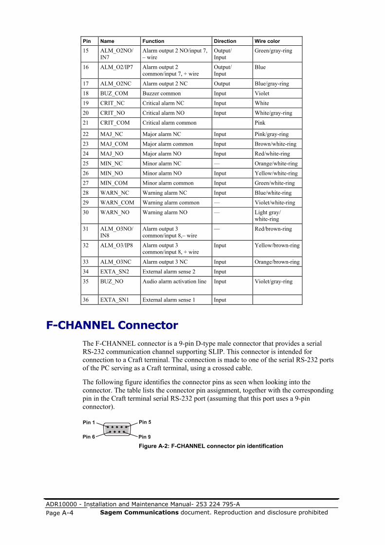
ADR10000 - Installation and Maintenance Manual- 253 224 795-A
Page A-4 Sagem Communications document. Reproduction and disclosure prohibited
Pin Name Function Direction Wire color
15 ALM_O2NO/ IN7
Alarm output 2 NO/input 7, – wire
Output/ Input
Green/gray-ring
16 ALM_O2/IP7 Alarm output 2 common/input 7, + wire
Output/ Input
Blue
17 ALM_O2NC Alarm output 2 NC Output Blue/gray-ring
18 BUZ_COM Buzzer common Input Violet
19 CRIT_NC Critical alarm NC Input White
20 CRIT_NO Critical alarm NO Input White/gray-ring
21 CRIT_COM Critical alarm common Pink
22 MAJ_NC Major alarm NC Input Pink/gray-ring
23 MAJ_COM Major alarm common Input Brown/white-ring
24 MAJ_NO Major alarm NO Input Red/white-ring
25 MIN_NC Minor alarm NC — Orange/white-ring
26 MIN_NO Minor alarm NO Input Yellow/white-ring
27 MIN_COM Minor alarm common Input Green/white-ring
28 WARN_NC Warning alarm NC Input Blue/white-ring
29 WARN_COM Warning alarm common — Violet/white-ring
30 WARN_NO Warning alarm NO — Light gray/ white-ring
31 ALM_O3NO/ IN8
Alarm output 3 common/input 8,– wire
— Red/brown-ring
32 ALM_O3/IP8 Alarm output 3 common/input 8, + wire
Input Yellow/brown-ring
33 ALM_O3NC Alarm output 3 NC Input Orange/brown-ring
34 EXTA_SN2 External alarm sense 2 Input
35 BUZ_NO Audio alarm activation line Input Violet/gray-ring
36 EXTA_SN1 External alarm sense 1 Input
F-CHANNEL Connector
The F-CHANNEL connector is a 9-pin D-type male connector that provides a serial RS-232 communication channel supporting SLIP. This connector is intended for connection to a Craft terminal. The connection is made to one of the serial RS-232 ports of the PC serving as a Craft terminal, using a crossed cable.
The following figure identifies the connector pins as seen when looking into the connector. The table lists the connector pin assignment, together with the corresponding pin in the Craft terminal serial RS-232 port (assuming that this port uses a 9-pin connector).
Figure A-2: F-CHANNEL connector pin identification

ADR10000 - Installation and Maintenance Manual- 253 224 795-A Sagem Communications document. Reproduction and disclosure prohibited Page A-5
Table A-3: F-CHANNEL connector pin assignment
Pin Name Function Direction Craft terminal serial port pin
1 — Not connected — Not connected
2 COM-F-RX F-channel receive Input Pin 3 (transmit output)
3 COM-F-TX F-channel transmit Output Pin 2 (receive input)
4 — Not connected — Not connected
5 GND Ground — Pin 5 (ground)
6, 7, 8, 9
— Not connected — Not connected
T3_1/T4_1 and T3_2/T4_2 Connectors
The T3_1/T4_1 and T3_2/T4_2 connectors are 9-pin D-type male connectors, each including two groups of lines:
Clock input (T3 2.048 MHz signal, ITU-T Rec. G.703 interface)
Clock output (T4 2.048 MHz signal, ITU-T Rec. G.703 interface)
The MAIN connector serves the main TMU, and the PROTECT connector serves the standby (protection) TMU. They are connected to the site timing reference distribution subsystem.
The following figure identifies the connector pins as seen when looking into the connector, and the table lists their pin assignment.
Figure A-3: T3_1/T4_1 and T3_2/T4_2 connectors pin identification
Table A-4: T3_1/T4_1 and T3_2/T4_2 connectors pin assignment
Pin Name Function Direction
1 SHIELD Shield - 2 CK_2M_MIL Clock input, low Input 3 SHIELD Shield - 4 CK_2M_MOL Clock output, low Output 5 — Not connected - 6 CK_2M_MIH Clock input, high Input 7 SHIELD Shield - 8 CK_2M_MOH Clock output, high Output 9 — Not connected -

ADR10000 - Installation and Maintenance Manual- 253 224 795-A
Page A-6 Sagem Communications document. Reproduction and disclosure prohibited
ETHERNET Connectors
The two ETHERNET connectors located on the ECU300/ECU300-F panel, designated MANAGEMENT MAIN and PROT/LCT, are 8-pin RJ-45 connectors that provide two Ethernet 10BaseT management interfaces (one for each MXC300 card installed in the ADR-10000 shelf).
At any time, only the interface connected to the MXC300 serving as the current main card is active; the interface connected to the MXC300 serving as the protection card is in standby to provide protection for the out-of-band management traffic.
Each ETHERNET connector is wired as a station port intended for direct connection through a straight cable to a port of a 10BaseT Ethernet hub.
The following figure identifies the connector pins as seen when looking into the connector. The table lists the pin assignment for a typical connector.
Figure A-4: ETHERNET connectors pin identification
Table A-5: ETHERNET connectors pin assignment
Designation Function Direction
TX+ Transmit, + wire Output
TX– Transmit, – wire Output RX+ Receive, + wire Input N/C Not connected RX– Receive, – wire Input FGND Frame ground N/C Not connected

ADR10000 - Installation and Maintenance Manual- 253 224 795-A Sagem Communications document. Reproduction and disclosure prohibited Page A-7
MXC300 DC Input Power Connectors The DC input power connector, designated POWER, is a 5-pin D-type male connector located on the MXC300 panel. The following figure identifies the functions of the POWER connector pins, as seen when looking into the connector.
Figure A-5: POWER input power connector pin functions
PIM2_63/B Connection Data The PIM2_63/B provides 63 balanced or unbalanced E1 tributary interfaces and has three pairs of 50-pin SCSI female connectors. Each connector pair supports 21 E1 interfaces. The upper connector in each pair serves the E1 receive signals and the lower the E1 transmit signals. The tributaries and type of signal (IN for receive, OUT for transmit) supported by each connector are marked near the connector: IN 1-21, OUT 1-21, IN 22-42, OUT 22-42, IN 43-63, and OUT 43-63.
The following figure identifies the connector pins in each pair as seen when looking into the connector. The tables list the pin assignment for a typical connector pair (for unbalanced interfaces, wire A is the center (tip) conductor, and wire B is the shield, or ring). These tables also list the color of the wire connected to the corresponding pin in the cables offered by SAGEM Communications' Network Solutions Division for connecting the tributary connector and a distribution frame. The tributary numbers appearing in these tables are given for the IN 1-21 and OUT 1-21 connectors. To obtain the correct tributary numbers for the other connectors, interpret the numbers as representing the number of the tributary in its group (for example, in connectors IN 22-42 and OUT 22-42, 7 represents E1 tributary 28; in connectors IN 43-63 and OUT 43-63, 12 represents E1 tributary 57).
UPPER
LOWER
Pin 1
Pin 1
Pin 26
Pin 26
Pin 25
Pin 25
Pin 50
Pin 50
Figure A-6: PIM2_63/B typical pair connectors pin identification

ADR10000 - Installation and Maintenance Manual- 253 224 795-A
Page A-8 Sagem Communications document. Reproduction and disclosure prohibited
Table A-6: PIM2_63/B typical receive lines (upper) connector pin assignment
Pin Name Function Direction Wire color
1 RTIP1 Receive, tributary 1, wire A Input Brown
2 RTIP2 Receive, tributary 2, wire A Input Red
3 RTIP3 Receive, tributary 3, wire A Input Orange
4 RTIP4 Receive, tributary 4, wire A Input Yellow
5 RTIP5 Receive, tributary 5, wire A Input Green
6 RTIP6 Receive, tributary 6, wire A Input Blue
7 RTIP7 Receive, tributary 7, wire A Input Violet
8 GND Shield — Brown/green-ring
9 RTIP8 Receive, tributary 8, wire A Input White
10 RTIP9 Receive, tributary 9, wire A Input Pink
11 RTIP10 Receive, tributary 10, wire A Input Brown/white-ring
12 RTIP11 Receive, tributary 11, wire A Input Orange/white-ring
13 RTIP12 Receive, tributary 12, wire A Input Green/white-ring
14 RTIP13 Receive, tributary 13, wire A Input Violet/white-ring
15 RTIP14 Receive, tributary 14, wire A Input Red/brown-ring
16 GND Shield — Light-gray/green-ring
17 RTIP15 Receive, tributary 15, wire A Input Orange/brown-ring
18 RTIP16 Receive, tributary 16, wire A Input Blue/brown-ring
19 RTIP17 Receive, tributary 17, wire A Input Light-gray/ brown-ring
20 RTIP18 Receive, tributary 18, wire A Input Brown/red-ring
21 RTIP19 Receive, tributary 19, wire A Input Yellow/red-ring
22 RTIP20 Receive, tributary 20, wire A Input Blue/red-ring
23 RTIP21 Receive, tributary 21, wire A Input White/red-ring
24 GND Shield — Yellow/green-ring
25 — Not connected — —
26 GND Shield — Orange/green-ring
27 RRING1 Receive, tributary 1, wire B Input Brown/gray-ring
28 RRING2 Receive, tributary 2, wire B Input Red/gray-ring
29 RRING3 Receive, tributary 3, wire B Input Orange/gray-ring
30 RRING4 Receive, tributary 4, wire B Input Yellow/gray-ring
31 RRING5 Receive, tributary 5, wire B Input Green/gray-ring
32 RRING6 Receive, tributary 6, wire B Input Blue/gray-ring
33 RRING7 Receive, tributary 7, wire B Input Violet/gray-ring
34 GND Shield — Violet/green-ring
35 RRING8 Receive, tributary 8, wire B Input White/gray-ring
36 RRING9 Receive, tributary 9, wire B Input Pink/gray-ring
37 RRING10 Receive, tributary 10, wire B Input Red/white-ring
38 RRING11 Receive, tributary 11, wire B Input Yellow/white-ring
39 RRING12 Receive, tributary 12, wire B Input Blue/white-ring
40 RRING13 Receive, tributary 13, wire B Input Light-gray/white-ring
41 RRING14 Receive, tributary 14, wire B Input Yellow/brown-ring
42 GND Shield — Blue/green-ring
43 RRING15 Receive, tributary 15, wire B Input Green/brown-ring
44 RRING16 Receive, tributary 16, wire B Input Violet/brown-ring

ADR10000 - Installation and Maintenance Manual- 253 224 795-A Sagem Communications document. Reproduction and disclosure prohibited Page A-9
Pin Name Function Direction Wire color
45 RRING17 Receive, tributary 17, wire B Input Pink/brown-ring
46 RRING18 Receive, tributary 18, wire B Input Light-gray/ red-ring
47 RRING19 Receive, tributary 19, wire B Input Green/red-ring
48 RRING20 Receive, tributary 20, wire B Input Violet/red-ring
49 RRING21 Receive, tributary 21, wire B Input Pink/red-ring
50 GND Shield — Pink/green-ring
Table A-7: PIM2_63 typical transmit lines (lower) connector pin assignment
Pin Name Function Direction Wire color
1 TTIP1 Transmit, tributary 1, wire A Output Brown/yellow-ring
2 TTIP2 Transmit, tributary 2, wire A Output Orange/yellow-ring
3 TTIP3 Transmit, tributary 3, wire A Output Blue/yellow-ring
4 TTIP4 Transmit, tributary 4, wire A Output Light-gray/ yellow-ring
5 TTIP5 Transmit, tributary 5, wire A Output Brown/blue-ring
6 TTIP6 Transmit, tributary 6, wire A Output Orange/blue-ring
7 TTIP7 Transmit, tributary 7, wire A Output Green/blue-ring
8 GND Shield — Pink/orange-ring
9 TTIP8 Transmit, tributary 8, wire A Output Light-gray/ blue-ring
10 TTIP9 Transmit, tributary 9, wire A Output Brown/orange-ring
11 TTIP10 Transmit, tributary 10, wire A Output Yellow/orange-ring
12 TTIP11 Transmit, tributary 11, wire A Output Blue/orange-ring
13 TTIP12 Transmit, tributary 12, wire A Output Light-gray/ orange-ring
14 TTIP13 Transmit, tributary 13, wire A Output Brown/violet-ring
15 TTIP14 Transmit, tributary 14, wire A Output Orange/ violet-ring
16 GND Shield — Pink/blue-ring
17 TTIP15 Transmit, tributary 15, wire A Output Green/violet-ring
18 TTIP16 Transmit, tributary 16, wire A Output Light-gray/ violet-ring
19 TTIP17 Transmit, tributary 17, wire A Output Brown/pink-ring
20 TTIP18 Transmit, tributary 18, wire A Output Orange/pink-ring
21 TTIP19 Transmit, tributary 19, wire A Output Green/pink-ring
22 TTIP20 Transmit, tributary 20, wire A Output Light-gray/ pink-ring
23 TTIP21 Transmit, tributary 21, wire A Output Pink/violet-ring
24 GND Shield — Pink/white-ring
25 — Not connected — —
26 GND Shield — White/brown-ring
27 TRING1 Transmit, tributary 1, wire B Output Red/yellow-ring
28 TRING2 Transmit, tributary 2, wire B Output Green/yellow-ring
29 TRING3 Transmit, tributary 3, wire B Output Violet/yellow-ring
30 TRING4 Transmit, tributary 4, wire B Output White/yellow-ring
31 TRING5 Transmit, tributary 5, wire B Output Red/blue-ring
32 TRING6 Transmit, tributary 6, wire B Output Yellow/blue-ring

ADR10000 - Installation and Maintenance Manual- 253 224 795-A
Page A-10 Sagem Communications document. Reproduction and disclosure prohibited
Pin Name Function Direction Wire color
33 TRING7 Transmit, tributary 7, wire B Output Violet/blue-ring
34 GND Shield — Black
35 TRING8 Transmit, tributary 8, wire B Output White/blue-ring
36 TRING9 Transmit, tributary 9, wire B Output Red/orange-ring
37 TRING10 Transmit, tributary 10, wire B Output Green/orange-ring
38 TRING11 Transmit, tributary 11, wire B Output Violet/orange-ring
39 TRING12 Transmit, tributary 12, wire B Output White/orange-ring
40 TRING13 Transmit, tributary 13, wire B Output Red/violet-ring
41 TRING14 Transmit, tributary 14, wire B Output Yellow/violet-ring
42 GND Shield — Black/white-ring
43 TRING15 Transmit, tributary 15, wire B Output Blue/violet-ring
44 TRING16 Transmit, tributary 16, wire B Output White/violet-ring
45 TRING17 Transmit, tributary 17, wire B Output Red/pink-ring
46 TRING18 Transmit, tributary 18, wire B Output Yellow/pink-ring
47 TRING19 Transmit, tributary 19, wire B Output Blue/pink-ring
48 TRING20 Transmit, tributary 20, wire B Output White/pink-ring
49 TRING21 Transmit, tributary 21, wire B Output Pink/yellow-ring
50 GND Shield — Black/yellow
EISMB/DIOM Connectors EISMB_804 and DIOM_04 are GbE/Fast Ethernet modules that provide electrical 10/100/1000BaseT ports. DIOM_08 is a Fast Ethernet module that provides 10/100BaseT ports. All these modules use 8-pin RJ-45 connectors for the electrical ports.
The following figure identifies the connector pins as seen when looking into the connector. The first table lists the pin out for a 10/100BaseT interface and the second for a 1000BaseT interface.
Figure A-7: 10/100BaseT connectors pin identification

ADR10000 - Installation and Maintenance Manual- 253 224 795-A Sagem Communications document. Reproduction and disclosure prohibited Page A-11
Table A-8: 10/100BaseT connectors pin assignment
Table A-9: 1000BaseT connector pin assignment
Pin Designation Function Direction
1 TR1P Transmit/Receive, pair 1, + wire
I/O
2 TR1N Transmit/Receive, pair 1, – wire
I/O
3 TR2P Transmit/Receive, pair 2, + wire
I/O
4 TR2N Transmit/Receive, pair 2 – wire
I/O
5 TR3P Transmit/Receive, pair 3 + wire
I/O
6 TR3N Transmit/Receive, pair 3 – wire
I/O
7 TR4P Transmit/Receive, pair 4 + wire
I/O
8 TR4N Transmit/Receive, pair 4 – wire
I/O
Pin Designation Function Direction
1 TD+ Transmit, + wire Output 2 TD– Transmit, – wire Output 3 RD+ Receive, + wire Input 6 RD– Receive, – wire Input

ADR10000 - Installation and Maintenance Manual- 253 224 795-A
Page A-12 Sagem Communications document. Reproduction and disclosure prohibited
xRAP-B/BM Connectors This section provides information on the connectors located on the xRAP-B/BM units.
Shelf DC Input Power Connectors
The shelf DC input power connectors, designated Shelf 1 and Shelf 2, are 5-pin D-type male connectors. The following figure identifies the functions of the shelf DC input connector pins, as seen when looking into the connector.
Figure A-8: xRAP-B/BM shelf DC input power connector pin functions
SHELF Alarm Connectors
The SHELF alarm connectors are 36-pin SCSI female connectors. Each connector is connected to the ALARMS connector of an ADR-10000 shelf. Refer to ALARMS Connector (on page A-1) for description. The following figure identifies the connector pins as seen when looking into the connector, and the table lists the pin assignment for this connector.
Pin 18
Pin 36
Pin 1
Pin 19
Figure A-9: SHELF alarm connector pin identification

ADR10000 - Installation and Maintenance Manual- 253 224 795-A Sagem Communications document. Reproduction and disclosure prohibited Page A-13
Table A-10: SHELF alarm connector pin assignment
Pin Name Function Direction
1 N/C Not connected --
2 ALM_IP1 Alarm input 1, + wire Input
3 ALM_IN1 Alarm input 1, – wire Input
4 ALM_IP2 Alarm input 2, + wire Input
5 ALM_IN2 Alarm input 2, – wire Input
6 ALM_IP3 Alarm input 3, + wire Input
7 ALM_IN3 Alarm input 3, – wire Input
8 ALM_IP4 Alarm input 4, + wire Input
9 ALM_IN4 Alarm input 4, – wire Input
10 ALM_O4 Alarm output 4 Output
11 N/C Not connected --
12 GND Ground --
13 ALM_O1 Alarm output 1 Output
14 N/C Not connected --
15 GND Ground --
16 ALM_O2 Alarm output 2 Output
17 N/C Not connected --
18 BUZZ Buzzer Input
19 N/C Not connected --
20 GND Ground --
21 CRIT_COM Critical alarm Output
22 N/C Not connected --
23 MAJ_COM Major alarm Output
24 GND Ground --
25 N/C Not connected --
26 GND Ground --
27 MIN_COM Minor alarm Output
28 N/C Not connected --
29 WARN_COM Warning alarm Output
30 GND Ground --
31 GND Ground --
32 ALM_O3 Alarm output 3 Output
33 N/C Not connected --
34 N/C Not connected --
35 GND Ground --
36 N/C Not connected --

ADR10000 - Installation and Maintenance Manual- 253 224 795-A
Page A-14 Sagem Communications document. Reproduction and disclosure prohibited
ALARMS Connector
The ALARMS connector is a SCSI 68-pin female connector that carries three groups of lines:
Eight external alarm inputs connected to the ALARM inputs of the ADR-10000 shelf. Four inputs are allocated to each ADR-10000 shelf. Each input is activated by closing a dry contact provided from the customer’s facility.
Eight sets of change-over relay contacts floating with respect to shelf ground, which serve as rack (bay) status outputs. Each couple of the eight relays is assigned to one of the output alarm lines of the two ADR-10000 shelves connected to the xRAP-B/BM.
Four sets of change-over relay contacts floating with respect to shelf ground, which serve as rack (bay) alarm indication lines. The relays, identified as critical, major, minor, and warning, are activated by the corresponding alarm relays of ADR-10000 shelves.
Two sets of change-over relay contacts floating with respect to shelf ground, which serve as Critical alarm buzzer activation signal. The relay is activated whenever a Critical alarm is detected in the corresponding shelf. The signal can be used to activate a local buzzer (Critical buzzer) in the customer's alarms collecting system.
Two lines for muting the Critical buzzer in the customer's alarms collecting system.
Relay contact ratings are 57.6 V in open state, and 1A in closed state.
The following figure identifies the ALARMS connector pins as seen when looking into the connector. The table lists the pin assignment for the ALARMS connector. This table also lists the color of the wire connected to the corresponding pin in the cables offered by SAGEM Communications' Network Solutions Division for connecting between the ALARMS connector and a distribution frame.
Figure A-10: ALARMS connector pin identification

ADR10000 - Installation and Maintenance Manual- 253 224 795-A Sagem Communications document. Reproduction and disclosure prohibited Page A-15
Table A-11: ALARMS connector pin assignment
Pin Designation Function Direction Wire color Assignment
1 CRIT_NC Critical alarm relay, normally closed contact
Output Black
2 CRIT_COM Critical alarm relay, common contact
Output Brown
3 CRIT_NO Critical alarm relay, normally open contact
Output Red
4 MAJ_NC Major alarm relay, normally closed contact
Output Orange
5 MAJ_COM Major alarm relay, common contact
Output Yellow
6 MAJ_NO Major alarm relay, normally open contact
Output Green
7 MIN_NC Minor alarm relay, normally closed contact
Output Blue
8 MIN_COM Minor alarm relay, common contact
Output Violet
9 MIN_NO Minor alarm relay, normally open contact
Output Gray
10 WARN_NC Warning alarm relay, normally closed contact
Output White
11 WARN_COM Warning alarm relay, common contact
Output Pink
12 WARN_NO Warning alarm relay, normally open contact
Output Light green
13 BUZZ_NC Buzzer relay, normally closed contact
Output Black/white
14 BUZZ_COM Buzzer relay, common contact
Output Brown/ white
15 BUZZ_NO Buzzer relay, normally open contact
Output Red/white
16 ALMO1_NO Output relay 1, normally open contact
Output Orange/ white
17 ALMO1_COM Output relay 1, common contact
Output Green/ white
18 ALMO1_NC Output relay 1, normally closed contact
Output Blue/white
19 ALMO2_NO Output relay 2, normally open contact
Output Violet/ white
20 ALMO2_COM Output relay 2, common contact
Output Red/black
21 ALMO2_NC Output relay 2, normally closed contact
Output Orange/ black
22 ALMO3_NO Output relay 3, normally open contact
Output Yellow/ black
23 ALMO3_COM Output relay 3, common contact
Output Green/ black
24 ALMO3_NC Output relay 3, normally closed contact
Output Gray/black
25 ALMO4_NO Output relay 4, normally open contact
Output Pink/black
Shelf 2 Shelf 2

ADR10000 - Installation and Maintenance Manual- 253 224 795-A
Page A-16 Sagem Communications document. Reproduction and disclosure prohibited
Pin Designation Function Direction Wire color Assignment
26 ALMO4_COM Output relay 4, common contact
Output Pink/green
27 ALMO4_NC Output relay 4, normally closed contact
Output Pink/red
28 ALMIN_1 External alarm input 1 Input Pink/violet
29 ALMIN_2 External alarm input 2 Input Light blue
30 GND ground Light blue/brown
31 ALMIN_3 External alarm input 3 Input Light blue/red
32 ALMIN_4 External alarm input 4 Input Light blue/violet
33 GND ground Light blue/black
34 BUZZ_OFF Buzzer mute Output Gray/green
35 CRIT_NC Critical alarm relay, normally closed contact
Output Gray/red
36 CRIT_COM Critical alarm relay, common contact
Output Gray/violet
37 CRIT_NO Critical alarm relay, normally open contact
Output Light green/black
38 MAJ_NC Major alarm relay, normally closed contact
Output Violet/black
39 MAJ_COM Major alarm relay, common contact
Output Black/white dots
40 MAJ_NO Major alarm relay, normally open contact
Output Brown/ white dots
41 MIN_NC Minor alarm relay, normally closed contact
Output Red/white dots
42 MIN_COM Minor alarm relay, common contact
Output Orange/ white dots
43 MIN_NO Minor alarm relay, normally open contact
Output Green/ white dots
44 WARN_NC Warning alarm relay, normally closed contact
Output Blue/white dots
45 WARN_COM Warning alarm relay, common contact
Output Violet/ white dots
46 WARN_NO Warning alarm relay, normally open contact
Output White/ black dots
47 BUZZ_NC Buzzer relay, normally closed contact
Output Yellow/ black dots
48 BUZZ_COM Buzzer relay, common contact
Output Green/ black dots
49 BUZZ_NO Buzzer relay, normally open contact
Output Light blue/ black dots
50 ALMO1_NO Output relay 1, normally open contact
Output Pink/black dots
51 ALMO1_COM Output relay 1, common contact
Output Red/black dots
52 ALMO1_NC Output relay 1, normally closed contact
Output Orange/ black dots
53 ALMO2_NO Output relay 2, normally open contact
Output Violet/black dots
54 ALMO2_COM Output relay 2, common contact
Output Gray/black dots
Shelf 1 Shelf 1

ADR10000 - Installation and Maintenance Manual- 253 224 795-A Sagem Communications document. Reproduction and disclosure prohibited Page A-17
Pin Designation Function Direction Wire color Assignment
55 ALMO2_NC Output relay 2, normally closed contact
Output Orange/red dots
56 ALMO3_NO Output relay 3, normally open contact
Output Yellow/red dots
57 ALMO3_COM Output relay 3, common contact
Output Green/red dots
58 ALMO3_NC Output relay 3, normally closed contact
Output Blue/red dots
59 ALMO4_NO Output relay 4, normally open contact
Output Violet/red dots
60 ALMO4_COM Output relay 4, common contact
Output Gray/red dots
61 ALMO4_NC Output relay 4, normally closed contact
Output White/red dots
62 ALMIN_1 External alarm input 1 Input Pink/red dots
63 ALMIN_2 External alarm input 2 Input Yellow/ white
64 GND ground Gray/white
65 ALMIN_3 External alarm input 3 Input Pink/white
66 ALMIN_4 External alarm input 4 Input Brown/ black
67 GND ground Blue/black
68 BUZZ_OFF Buzzer mute Output Gray/white dots


ADR10000 - Installation and Maintenance Manual- 253 224 795-A Sagem Communications document. Reproduction and disclosure prohibited Page B-1
In this appendix: Installing Equipment Racks ............................................................................ B-1 19" Rack Installation....................................................................................... B-6
Installing Equipment Racks
Rack Floor Marking
You need to mark out the rack floor plan before installing the rack.
Before you start:
Before starting, find the prescribed location of each equipment rack.
If you have not yet unpacked the rack and the associated mounting kits, do so now (see Unpacking and Performing Visual Inspection (on page 3-11)).
B Rack Installation
NOTE: The instructions in this Appendix are relevant to the installation of all rack types. However, it is recommended that ADR-10000 shelves be installed in ETSI A racks.

ADR10000 - Installation and Maintenance Manual- 253 224 795-A
Page B-2 Sagem Communications document. Reproduction and disclosure prohibited
To mark out the rack floor plan:
1. For each rack, mark out the floor at the rack location(s) according to the floor plan template corresponding to the type of rack being installed:
ETSI A racks: Use template of diagram a. of Mounting diagrams for ETSI racks (on page B-3).
23" rack: Use template of diagram a. of Mounting diagrams for 19" and 23" racks (on page B-4).
19" rack: Use template of diagram b. of Mounting diagrams for 19" and 23" racks (on page B-4).
The marked locations are a helpful guide for positioning the racks.
2. If the installation is located at a site with a floating (suspended) floor, also mark out all cable entry slots.
3. For concrete or wooden floors, mark out all the points designated for equipment bolting.
Rack Installation on Concrete Floors
This section describes how to install racks on concrete floors.
To mount the rack on a concrete floor:
1. Drill the required mounting holes in accordance with the appropriate template (diagram a. of Mounting diagrams for ETSI racks (on page B-3) diagram a. or b. of Mounting diagrams for 19" and 23" racks (on page B-4)).
2. Insert expansion shields into the holes.
3. Position the rack over the mounting holes.
4. Secure the rack to the floor with the bolts supplied in the mounting kit, in accordance with diagram b. of Mounting diagrams for ETSI racks, or diagram c. of Mounting diagrams for 19" and 23" racks.
Rack Installation on Wooden Floors
This section describes how to install racks on wooden floors.
To mount the rack on a wooden floor:
1. Drill the required mounting holes in accordance with the appropriate template (see the following figures), using a 5-mm drill bit.
2. Position the rack over the mounting holes.

ADR10000 - Installation and Maintenance Manual- 253 224 795-A Sagem Communications document. Reproduction and disclosure prohibited Page B-3
3. Secure the rack to the floor using the appropriate wood screws (see the following figures).
Figure B-1: Mounting diagrams for ETSI racks

ADR10000 - Installation and Maintenance Manual- 253 224 795-A
Page B-4 Sagem Communications document. Reproduction and disclosure prohibited
a. 23” wide bay mounting hole drilling template
6-1/2” 9-29/32”
18-1/2”
25-7/8”
1-45/64”
3-11/16”
12 mm - 4 places
c. Bolting diagram – concrete floor
SCREW M12X50
FLAT WASHER
SPACER
FLOOR LEVEL
M12 EXPANSION SHIELD
b. 19” wide bay mounting hole drilling template
6-1/2” 9-29/32”
14-1/2”
21-7/8”
1-45/64”
3-11/16”
SQUARE WASHER
ANCHOR BRACKET
UNEQUAL FLANGE RACK
4” STAGE
OPEN DUCT
φ12 mm - 4 places
Figure B-2: Mounting diagrams for 19" and 23" racks
Rack Installation on Floating (Suspended) Floors
This section describes how to install racks on floating (suspended) floors.
To mount the rack on a floating (suspended) floor:
1. Drill the required mounting holes in the suspended floor in accordance with the appropriate template.
2. Position the rack over the mounting holes.
3. Secure the rack to the floor in accordance with diagram c. of Mounting diagrams for ETSI racks (on page B-3).

ADR10000 - Installation and Maintenance Manual- 253 224 795-A Sagem Communications document. Reproduction and disclosure prohibited Page B-5
Suspended Overhead Tray Assembly
This section describes how to install racks on a suspended overhead tray.
To mount the rack on a suspended overhead tray:
1. Refer to the suspended overhead tray diagram (see the following figure) and position the overhead rack securing brackets.
2. Secure the rack to the overhead cabling trays, using the adjustable brackets. 2200 mm high racks may also be attached to the ceiling; 2600 mm racks are generally attached only to the ceiling.
UPPER BRACKET
LOCK WASHER
LOCK WASHER
SCREW M8X20
SCREW M8X20
FLAT WASHER
FLAT WASHER
FLAT WASHER
NUT M8
NUT M8
CEILING
640
MAX
50 M
IN
550
CEILING
Figure B-3: Rack mounting diagram for attachment to suspended overhead tray (2200
mm rack)
Installing Extendable Rails
In high-density installations, it may be necessary to install the xRAP above the rack using the extendable installation rails available from SAGEM Communications.
In this case, attach the extendable installation rails to the top of the rack before installing the equipment.
Rack Grounding
Immediately after installing the rack, connect its grounding stud to the prescribed grounding point on the site grounding bar. Use a grounding lead that meets the Rack grounding requirements listed in section Before You Start.

ADR10000 - Installation and Maintenance Manual- 253 224 795-A
Page B-6 Sagem Communications document. Reproduction and disclosure prohibited
19" Rack Installation The ADR-10000 can also be installed in European 19" racks. This is accepted under the limitations that the rack's general dimensions are according to the following figure. Any other European 19” rack must first be examined and approved by SAGEM Communications' Network Solutions Division Mechanical Department.
Top view
597
605.
5
667
Side view
600
597512
625
355
597
1912
Front view Rear view
597
2021
515538
500
44Z
Mounting angleForemost positionDetail Z
Max
imum
dist
ance
betw
een
leve
ls49
9mm
50044
515538
Figure B-4: Example of an approved European 19" rack

ADR10000 - Installation and Maintenance Manual- 253 224 795-A Sagem Communications document. Reproduction and disclosure prohibited Page C-1
1. Af-phy-0064.000 – ATM Forum E1 Physical Layer Interface.
2. Af-phy-0086.000 – ATM Forum IMA V1.0.
3. Af-phy-0086.001 – ATM Forum IMA V1.1.
4. Af-phy-00121.00 – ATM Forum Traffic Management Specifications V4.1.
5. ANSI T1.105-2001 – Synchronous Optical Network (SONET) - Basic Description including Multiplex Structure, Rates, and Formats.
6. BS ISO/IEC-3309 – Information Technology – Telecommunications and Information Exchange between Systems – High-Level Data Link Control (HDLC) Procedures – Frame Structure.
7. BS ISO/IEC-9595, Information Technology – Open Systems Interconnection – Common Management Information Services.
8. EN- 60950-1 ed1 (2001/10) – Electrical Safety.
9. ETS 300 386 (2003/01) – Electromagnetic compatibility and Radio spectrum Matters (ERM); Telecommunication network equipment; Electromagnetic Compatibility (EMC) requirements.
10. ETS 300 132 -2 (2003/03) – Environmental Engineering (EE); Power Supply Interface at the Input to Telecommunications Equipment.
11. ETSI ETR 114 – Functional Architecture of SDH Transport Networks.
12. ETSI EN 300 019-1-1 (2003/04) – Environmental Engineering (EE); Environmental Conditions and Environmental Tests for Telecommunications Equipment; Storage.
13. ETSI EN 300 019-1-2 (2003/04) – Environmental Engineering (EE); Environmental Conditions and Environmental Tests for Telecommunications Equipment; Transportation.
14. ETSI EN 300 019-1-2 (2004/07) – Environmental Engineering (EE); Environmental Conditions and Environmental Tests for Telecommunications Equipment; Stationary use at weather protected location.
15. FTZ 1 TR9 (2002/06) - Deutsche Telekom A.G. EMC Requirements.
16. GR-1089-CORE (2006/06) – Electromagnetic Compatibility and Electrical Safety – Generic Criteria for Network Telecommunications Equipment.
C Reference Documents

ADR10000 - Installation and Maintenance Manual- 253 224 795-A
Page C-2 Sagem Communications document. Reproduction and disclosure prohibited
17. GR-1209-CORE (2001/03) – Generic Requirements for Passive Optical Components.
18. GR-1230-CORE – SONET Bidirectional Line-Switched Ring Equipment Generic Criteria.
19. GR-1312-CORE (1999/04) – Generic Requirements for Optical Fiber Amplifiers and Proprietary Dense Wavelength-Division Multiplexed Systems.
20. GR-1400-CORE – SONET Dual-Fed Unidirectional Path Switched Ring (UPSR) Equipment Generic Criteria.
21. GR-253-CORE (2000/09) – Synchronous Optical Network (SONET) Transport Systems: Common Generic Criteria.
22. GR-383-CORE – COMMON LANGUAGE® Equipment Codes (CLEI™ Codes) – Generic Requirements for Bar Code Labels.
23. GR-63-CORE (2006/03) – Network Equipment Building System (NEBS) Requirements: Physical Protection.
24. IEC-68 – Environmental Testing.
25. IEC 917 – Modular Order for the Development of Mechanical Structures for Electronic Equipment Practices.
26. IEC 60825-1 (2001/08): Safety of Laser Products – Part 1: Equipment Classification, Requirements, and User Guide.
27. IEC 60825-2 (2000/05): Safety of Laser Products – Part 2: Safety of Optical Fiber Communication System.
28. IEEE 802.1ad - Virtual Bridged Local Area Networks—Revision—Amendment 4: Provider Bridges.
29. IEEE 802.1D - Media access control (MAC) Bridges (Incorporates IEEE 802.1t-2001 and IEEE 802.1w).
30. IEEE 802.1P - Traffic Class Expediting and Dynamic Multicast Filtering.
31. IEEE 802.1Q - Virtual Bridged Local Area Networks—Revision.
32. IEEE 802.1w - Rapid Reconfiguration of Spanning Tree.
33. IEEE 802.3-2005 – Carrier Sense Multiple Access with Collision Detection (CSMA/CD) Access Method and Physical Layer Specifications.
34. IEEE 802.3ad – Link Aggregation.
35. IEEE 802.3ah – Ethernet in the First Mile (Link OAM).
36. IEEE 802.3x - Full Duplex Operation and Flow Control Protocol.
37. IETF, RFC-1493 – Definition of Managed Objects for Bridges.
38. IETF, RFC-1643 - Ethernet-like Interfaces.
39. IETF, RFC-1662 – PPP in HDLC-Life Framing.
40. IETF, RFC-1757 - Remote Network Monitoring Management Information Base.

ADR10000 - Installation and Maintenance Manual- 253 224 795-A Sagem Communications document. Reproduction and disclosure prohibited Page C-3
41. IETF, RFC-2108 – Definitions of Managed Objects for IEEE 802.3 Repeater Devices using SMIv2.
42. IETF, RFC 2401 – Security Architecture for the Internet Protocol.
43. IETF, RFC 2409 – Internet Key Exchange Protocol (IKE).
44. IETF, RFC-2615 – PPP over SONET/SDH.
45. IETF, RFC-2665 – Definitions of Managed Objects for the Ethernet-like Interface Types.
46. IETF, RFC-2674 - Bridge MIB with VLAN/Traffic Classes/Multicast Extensions.
47. IETF, RFC-2702 - Requirements for Traffic Engineering Over MPLS.
48. IETF, RFC-2737 – Entity MIB (Version 2).
49. IETF, RFC-2819 – Remote Network Monitoring Management Information Base.
50. IETF, RFC-2863 - Interfaces Group MIB.
51. IETF, RFC-3031 - Multiprotocol Label Switching Architecture.
52. IETF, RFC-3032 - MPLS Label Stack Encoding.
53. IETF, RFC-3270 - Multi-Protocol Label Switching (MPLS) Support of Differentiated Services.
54. IETF, RFC-3443 - Time To Live (TTL) Processing in Multi-Protocol Label Switching (MPLS) Networks.
55. IETF, RFC-3812 - Multiprotocol Label Switching (MPLS) Traffic Engineering (TE) Management Information Base (MIB).
56. IETF, RFC-3813 - Multiprotocol Label Switching (MPLS) Label Switching Router (LSR) Management Information Base (MIB).
57. IETF,RFC-3916 - Requirements for Pseudo-Wire Emulation Edge-to-Edge (PWE3).
58. IETF, RFC-3985 - Pseudo Wire Emulation Edge-to-Edge (PWE3) Architecture.
59. IETF, RFC-4090 - Fast Reroute Extensions to RSVP-TE for LSP Tunnels.
60. IETF, RFC-4125 - Maximum Allocation Bandwidth Constraints Model for Diffserv-aware MPLS Traffic Engineering.
61. IETF, RFC-4126 - Max Allocation with Reservation Bandwidth Constraints Model for Diffserv-aware MPLS Traffic Engineering & Performance Comparisons.
62. IETF, RFC-4379 - Detecting Multi-Protocol Label Switched (MPLS) Data Plane Failures.
63. IETF, RFC-4448 - Encapsulation Methods for Transport of Ethernet over MPLS Networks.

ADR10000 - Installation and Maintenance Manual- 253 224 795-A
Page C-4 Sagem Communications document. Reproduction and disclosure prohibited
64. IETF Drafts:
a. Martini encapsulation, draft-martini-l2circuit-encap-mpls.
b. VPLS draft, draft-ietf-l2vpn-vpls-ldp.
c. draft-ietf-pwe3-ethernet-encap.
d. draft-sajassi-l2vpn-vpls-multicast-congruency.
e. draft-ietf-l2vpn-vpls-mcast-reqts.
f. draft-ietf-magma-snoop.
g. draft-ietf-mpls-rsvp-te-p2mp.
h. draft-vasseur-mpls-backup-computation.
65. ISO 9595, ISO 9596 – CMISE Specification.
66. ITU-T Recommendation I.356 – ATM Layer Cell Transfer Performance.
67. ITU-T Recommendation I.361 – ATM Layer Specification.
68. ITU-T Recommendation I.371 – Traffic Control and Congestion Control.
69. ITU-T Recommendation I.610 – ATM Operation and Maintenance Principles.
70. ITU-T Recommendation G.650 – Definition and Test Methods for the Relevant Parameters of Single-Mode Fibers.
71. ITU-T Recommendation G.651 (1998/02) – Characteristics of a 50/125 µm Multimode Graded Index Optical Fiber Cable.
72. ITU-T Recommendation G.652 (2006/05) – Characteristics of a Single-Mode Optical Fiber Cable.
73. ITU-T RecommendationG.653 (2003/12) – Characteristics of a Dispersion-Shifted Single-Mode Optical Fiber Cable.
74. ITU-T RecommendationG.654 (2004/06) – Characteristics of a Cut-off Shifted Single-Mode Optical Fiber Cable.
75. ITU-T Recommendation G.655 (2006/06) – Characteristics of a Non-Zero Dispersion Shifted Single-Mode Optical Fiber Cable.
76. ITU-T Recommendation G.661 (2006/03) – Definition and Test Methods for the Relevant Generic Parameters of Optical Amplifier Devices and Subsystems.
77. ITU-T Recommendation G.662 (2005/07) – Generic Characteristics of Optical Fiber Amplifier Devices and Subsystems.
78. ITU-T Recommendation G.663 (2000/04) – Application Related Aspects of Optical Fiber Amplifier Devices and Subsystems.
79. ITU-T Recommendation G.664 (2006/03) – Optical Safety Procedures and Requirements for Optical Transport Systems.
80. ITU-T Recommendation G.671 (2005/01) – Transmission Characteristics of Passive Optical Components.
81. ITU-T Recommendation G.691 (2006/03) – Optical Interfaces for Single Channel SDH Systems with Optical Amplifiers and STM-64 Systems (Draft).

ADR10000 - Installation and Maintenance Manual- 253 224 795-A Sagem Communications document. Reproduction and disclosure prohibited Page C-5
82. ITU-T Recommendation G.692 (1998/10) – Optical Interfaces for Multi-Channel Systems with Optical Amplifiers.
83. ITU-T Recommendation G.694.1 (2002/06) – Spectral Grids for WDM Applications: DWDM Frequency Grid.
84. ITU-T Recommendation G.694.2 (2003/12) – Spectral Grids for WDM Applications: CWDM Wavelength Grid.
85. ITU-T Recommendation G.695 (2005/01) – Optical Interfaces for Coarse Wavelength Division Multiplexing Applications.
86. ITU-T Recommendation G.703 (2001/11) – Physical/Electrical Characteristics of Hierarchical Digital Interfaces.
87. ITU-T Recommendation G.704 (1998/10) – Synchronous Frame Structures Used at 1544, 6312, 2048, 8448 and 44 736 kbps Hierarchical Levels.
88. ITU-T Recommendation G.706 – Frame Alignment and CRC Procedures Relating to Basic Frame Structure Defined in Rec G.704.
89. ITU-T Recommendation G.707 – Network Node Interface for the Synchronous Digital Hierarchy.
90. ITU-T Recommendation G.709 – Network Node Interface for OTN.
91. ITU-T Recommendation G.772 (1988/11) – Protected Monitoring Points Provided on Digital Transmission Systems.
92. ITU-T Recommendation G.774 & G774.n – SDH Information Model.
93. ITU-T Recommendation G.781 – Synchronization Layer Functions.
94. ITU-T Recommendation G.783 – Characteristics of SDH Equipment Functional Blocks.
95. ITU-T Recommendation G.784 – Synchronous Digital Hierarchy (SDH) Management.
96. ITU-T Recommendation G.798 – Characteristics of OTN Hierarchy Equipment Functional Blocks.
97. ITU-T Recommendation G.803 – Architectures of Transport Networks based on the Synchronous Digital Hierarchy.
98. ITU-T Recommendation G.805 – Generic Functional Architecture of Transport Networks.
99. ITU-T Recommendation G.806 – Characteristics of Transport Equipment –Description Methodology and Generic Functionality.
100. ITU-T Recommendation G.811 (1996/09) – Timing Characteristics of Primary Reference Clocks.
101. ITU-T Recommendation G.812 (2004/06) – Timing Requirements of Slave Clocks Suitable for Use as Node Clocks in Synchronization Networks.
102. ITU-T Recommendation G.813 (2003/03) – Timing Characteristics of SDH Equipment Slave Clocks (SEC).
103. ITU-T Recommendation G.823 (2000/03) – The Control of Jitter and Wander within Digital Networks Based on the 2048 kbit/s Hierarchy.

ADR10000 - Installation and Maintenance Manual- 253 224 795-A
Page C-6 Sagem Communications document. Reproduction and disclosure prohibited
104. ITU-T Recommendation G.825 (2000/03) – The Control of Jitter and Wander within Digital Networks Based on the SDH (Draft).
105. ITU-T Recommendation G.8251 (2001/11) – The Control of Jitter and Wander within the Optical Transport Network (OTN).
106. ITU-T Recommendation G.826 – Error Performance Parameters and Objectives for International, Constant Bit Rate Digital Paths at or above the Primary Rate.
107. ITU-T Recommendation G.828 – Error Performance Parameters and Objectives for International, Constant Bit Rate Synchronous Digital Paths.
108. ITU-T Recommendation G.829 – Error Performance Events for SDH Multiplex and Regenerator Sections.
109. ITU-T Recommendation G.841 – Types and Characteristics of SDH Network Protection Architectures.
110. ITU-T Recommendation G.842 – Inter-Working of SDH Protection Architectures.
111. ITU-T Recommendation G.872 – Architecture of Optical Transport Networks.
112. ITU-T Recommendation G.874 – Management Aspects of the Optical Transport Network Element.
113. ITU-T Recommendation G.875 – OTN Management Information Model for the NE View.
114. ITU-T Recommendation G.957 (2006/03) – Optical Interfaces for Equipment and Systems relating to the Synchronous Digital Hierarchy.
115. ITU-T Recommendation G.959.1 (2006/03) – Optical Transport Network Physical Layer Interfaces.
116. ITU-T Recommendation G.975 – Forward Error Correction for Submarine Systems.
117. ITU-T Recommendation G.7041 – Generic Framing Procedure (GFP).
118. ITU-T Recommendation G.7042 – Link Capacity Adjustment Scheme (LCAS) for Virtual Concatenated Signals.
119. ITU-T Recommendation G.8010/Y.1306 - Architecture of Ethernet Layer Networks.
120. ITU-T Recommendation G.8011/Y.1307 - Ethernet Services Framework.
121. ITU-T Recommendation G.8011.1/Y.1307.1 - Ethernet Private Line Service.
122. ITU-T Recommendation G.8011.2/Y.1307.2 - Ethernet Virtual Private Line Service.
123. ITU-T Recommendation G.8012/Y.1308 - Ethernet UNI and Ethernet NNI.
124. ITU-T Recommendation Y.1710 - Requirements for Operation & Maintenance functionality for MPLS networks.
125. ITU-T Recommendation Y.1711 - Operation & Maintenance mechanism for MPLS networks.
126. ITU-T Recommendation M.3010 – Principles for a Telecommunications Management Network.

ADR10000 - Installation and Maintenance Manual- 253 224 795-A Sagem Communications document. Reproduction and disclosure prohibited Page C-7
127. ITU-T Recommendation M.3100 – Generic Network Information Model.
128. ITU-T Recommendation Q.821 – Alarm Surveillance.
129. ITU-T Recommendation Q.822 – Performance Monitoring.
130. ITU-T Recommendations X.217, X.227 – ACSE Specification.
131. ITU-T Recommendations X.219, X.229 – ROSE Specification.
132. ITU-T Recommendation X.721 Information Technology – Open Systems Interconnection – Structure of Management Information: Definition of Management Information.
133. MEF4 Metro Ethernet Network Architecture Framework Part 1: Generic Framework.
134. MEF6 Metro Ethernet Services Definitions.
135. MEF7 EMS-NMS Information Model.
136. MEF9 Test Suite for Ethernet Services at the UNI.
137. MEF10 Ethernet Service Attributes.
138. MEF11 User Network Interface (UNI) Requirements and Framework.
139. MEF12 Metro Ethernet Network Architecture Framework Part 2: Ethernet Services Layer.
140. MEF14 Test Suite for Ethernet Traffic Management.
141. NIST, FIPS PUB 197 – Advanced Encryption Standard (AES).
142. NIST, FIPS 140-2 – Security Requirements for Cryptographic Modules.
143. UL 60950 (2002/03): Safety of Information Technology Equipment.


If you encounter problems during installation or use, do not hesitate to:
CONTACT OUR "SDH PRODUCTS" HOTLINE
ON A SINGLE TELEPHONE NUMBER: in mainland France : 01 40 70 60 60 or from abroad : 33 1 40 70 60 60
ON A SINGLE FAX NUMBER:
in mainland France : 01 40 70 60 80 or from abroad : 33 1 40 70 60 80
ON A SINGLE Email address:
Don't forget to provide yourself with your customer number which is written on your invoice.

Registered office: Le Ponant de Paris - 27, rue Leblanc - 75 015 PARIS - France Tel.: +33 (0)1 58 11 77 00 - Fax: +33 (0)1 58 11 77 77 http://www.sagem-communications.com SAS with the capital of 158 291 895 € - 440 294 510 RCS Paris