adiabatic shearband in wha in high-strain-rate compression · adiabatic shearband in wha in...
TRANSCRIPT
Ž .Mechanics of Materials 28 1998 227–236
Adiabatic shearband in WHA in high-strain-rate compression
D.S. Kim a,), S. Nemat-Nasser b, J.B. Isaacs b, D. Lischer b
a CiÕil and Architecture Group, Hyundai Engineering, 51-1 Pangyi-Dong, Songpa-Ku, Seoul 138-052, South Koreab Center of Excellence for AdÕanced Materials, Department of Applied Mechanics and Engineering Sciences,
UniÕersity of California, San Diego, La Jolla, CA 92093-0416, USA
Received 19 November 1996; revised 7 November 1997
Abstract
wUsing UCSD’s recovery Hopkinson technique Nemat-Nasser, S., Isaacs, J.B., Starrett, J.E., 1991. Hopkinson techniquesxfor dynamic recovery experiments. Proc. R. Soc. London, A135, 371 , enhanced for high-temperature compression
wexperiments Nemat-Nasser, S., Isaacs, J., 1997. Direct measurement of isothermal flow stress of metal at elevatedxtemperatures and high strain rates. Acta. Met., 45, 907 , two techniques are developed to create adiabatic shearbands in
Ž . Ž .tungsten heavy alloy WHA samples at high strain rates 3000 to 5000rs , and the results are compared with those obtainedŽ y3 .at low strain rates 10 rs . In the first technique, a cylindrical sample is subjected to a single compression pulse and is
recovered without being subjected to any additional loading. The change in the surface temperature of the sample ismeasured during its high-strain-rate deformation, using an infrared technique. In the second scheme, a small circularcylindrical sample is constrained at both ends by thin confining rings and then subjected to axial compression in the recoveryHopkinson bars at various initial temperatures. Barreling of the sample takes place under somewhat controlled conditionsand hence, this experiment is referred to as the ‘controlled barreling’ test. The confining rings promote shearband formation.Since the samples have been subjected to only a single compression pulse, the experiments allow correlating the resultingmicrostructural changes with the corresponding temperature and loading histories. SEM observations revealed thatintergranular fracture occurs within the shearbands in the Fe–Ni matrix. Some transgranular fracture was also observed. Thehigh-strain-rate controlled barreling test performed at the initial room temperature, invariably leads to adiabatic shearband-
Ž .ing. However, at suitably high initial temperatures e.g., 500–7008C , the shearbanding gives way to a diffused yet highlylocalized deformation. In addition, the strain, strain-rate, and temperature dependency of the flow stress of this material isquantified, based on high-strain-rate isothermal and adiabatic, and quasi-static flow stress measurements. These and relatedfeatures are discussed in this paper. q 1998 Elsevier Science Ltd. All rights reserved.
Keywords: Shearband; High-strain-rate compression; WHA; Infrared measurement
1. Introduction
In a ballistic environment, the deformation of aŽ .conventional depleted uranium DU penetrator
quickly localizes into intense adiabatic shearbands,
) Corresponding author.
promoting its penetrability by flaking off and mini-mizing the size of the impacting face of the penetra-tor. Therefore, the uranium projectile is an efficientpenetrator. The DU however, causes health hazards.There is, therefore, a need to replace the DU penetra-
Žtors with environmentally safe materials Magness.and Farrand, 1990 .
0167-6636r98r$19.00 q 1998 Elsevier Science Ltd. All rights reserved.Ž .PII: S0167-6636 97 00068-9
( )D.S. Kim et al.rMechanics of Materials 28 1998 227–236228
The efficiency of the penetrator, in general, de-pends on its propensity for strain and heat localiza-tion, and on its characteristic failure through forma-tion of adiabatic shearbands at oblique planes with
Žrespect to the penetrator axis Keckes and Hall,.1992 . Low heat capacity material requires relatively
little heating to raise the temperature, the low heatconductivity confines the heat within the strain-local-ized zones. This can lead to local thermal softeningand the quick formation of intense adiabatic shear-
Ž .bands Zener and Hollomon, 1944 . It is known thatat least 90% of the plastic work in quasi-static
Ždeformations, is converted into heat Taylor and.Quinney, 1934 , and, at high strain rates, almost all
of the plastic work is used to heat the materialŽ .Kapoor and Nemat-Nasser, 1997 .
During shearband formation in tungsten heavyŽ .alloy WHA , plastic deformation is localized within
Ža very small region in a short time interval less than.a few hundred microseconds . High-strain-rate dy-
namic deformation of the WHA includes effects suchas strain rate, thermal softening, and work hardeningdue to plastic strain accumulation and microstruc-
Žtural effects Clifton et al., 1984; Meyers et al.,.1995; Nemat-Nasser et al., 1994 .
The objective of this research was to examineexperimentally the performance of a tungsten com-posite, focusing specifically on the shearband forma-tion under compressive high-strain-rate loading atvarious initial temperatures.
The formation of adiabatic shearbands in cylindri-cal samples is examined, using two experimentaltechniques. In the first experiment, the sample issubjected to uniaxial compression in UCSD’s recov-
Ž .ery Hopkinson bars Nemat-Nasser et al., 1991 , atŽ .various strain rates 3000–5000rs . The tests are
performed so that the sample barrels as it deforms,due to the constraint of frictional contact with thebars. The surface temperature of the sample is mea-sured, using an infrared technique. CompressionHopkinson experiments have been performed on
Ž .WHA composites by Ramesh and Coates 1992 andŽ .Lankford et al. 1992 , using the classical Kolsky
Ž .split-Hopkinson technique Kolsky, 1949 . Since theKolsky technique is not a recoÕery experiment, thesample is generally subjected to several uncontrolledcompressive pulses and therefore, its microstructuralchanges cannot be correlated with the first stress
pulse which is actually recorded, and from which thecorresponding stress–strain relation is establishedŽ .Nemat-Nasser et al., 1991 . In UCSD’s technique,all tension or compression pulses which are reflectedfrom or transmitted through the sample during theloading of the sample, are trapped at the other endsof the two bars. Thus, the deformation of the samplecorresponds to exactly one controlled stress pulseŽ .tension or compression .
In the present study, controlled barreling of thesamples is introduced by placing confining rings atthe two ends of the sample, before the sample iscompressed in the Hopkinson bar. Using a recoveryHopkinson technique which is supplemented by a
Žfurnace in an appropriate manner see the work of.Nemat-Nasser and Isaacs, 1997 , the experiments are
performed at various initial temperatures, i.e., 258,3258, 5258, and 7258C. Thus, the effect of tempera-ture on the material’s propensity for shearbandingcan be quantitatively evaluated.
2. Material and samples
Tungsten is a refractory metal, having the bccstructure with no phase transformations betweenroom temperature and its melting point of 34108C.The melting temperature of the fcc nickle-basedalloy in WHA is approximately 15008C. The me-chanical properties of bcc and fcc metals are dis-tinctly different, since bcc metals exhibit a muchgreater temperature- and strain-rate-sensitivity. See,
Ž .e.g., the works of Nemat-Nasser and Isaacs 1997
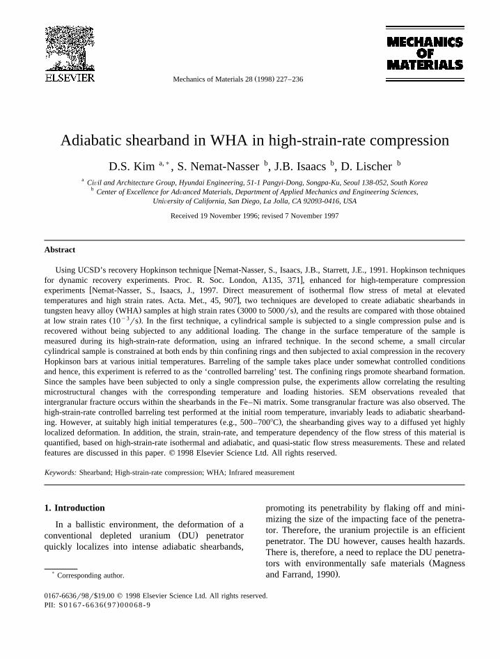
ŽFig. 1. SEM micrograph of intact W–Fe–Ni magnifications.1000= .
( )D.S. Kim et al.rMechanics of Materials 28 1998 227–236 229
Ž .and Nemat-Nasser and Li 1998 for experimentalŽ .results and modeling of a bcc tantalum and an fcc
Ž .copper metal.The 93W–4.9Ni–2.1Fe alloy is used for this study.
Ž .Consisting of two phases, the bcc W-phase parti-Ž .cles are embedded in the fcc Fe–Ni-phase matrix.
The spheroidal tungsten particles are surrounded bya continuous Fe–Ni matrix phase; see Fig. 1.
A number of cylindrical specimens, measuring anominal 0.48 cm in diameter and 0.38 cm in length,were fabricated from the W–Fe–Ni rod for dynamichigh-strain-rate compression tests. Representative
specimens were selected for quasi-isothermal com-pression to observe the strain hardening response ofthe material at different strain rates and differenttemperatures.
3. Experimental techniques—infrared tempera-ture sensor
Measuring the rapidly changing temperature of amaterial at high strain rates requires a non-contact-ing, remotely sensing high speed device. The in-
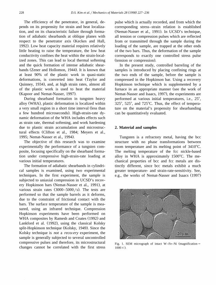
Ž . Ž .Fig. 2. Infrared sensing high-speed temperature measurement system: a overall setup of the infrared and the recovery Hopkinson bar; bschematic of the infrared system.
( )D.S. Kim et al.rMechanics of Materials 28 1998 227–236230
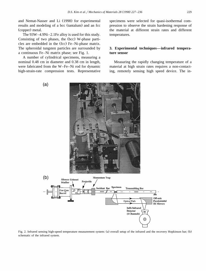
Ž .Fig. 3. a Voltages from Hopkinson bar strain gauges and in-Ž . Ž .frared system superimposed at event time ;250 ms ; b Tem-
Ž .perature history of W–Fe–Ni alloy during impact ´ ;4000rs˙from four-channel infrared detector.
frared measurement technique used in our experi-ments incorporates a mirrored imaging system, avisible laser alignment system, a four-channel in-frared detector, four high speed amplifiers and amulti-channel high speed digitizer; see Fig. 2.
The imaging system employs two 3-in. diameteroff-axis paraboloidal rhodium mirrors with equalfocal lengths of 119 mm. The first mirror is posi-tioned so that the sample is located at the focusresulting in a collimated beam of radiation emittedfrom a small area of the sample surface. The secondmirror, positioned approximately a meter away, re-flects and focuses the radiation into the infrareddetector. Since the magnification of this optical sys-tem is one, the area of sample surface to be mea-sured is equal to the active area of the detector, 2mm. An adjustable aperture is installed in front of
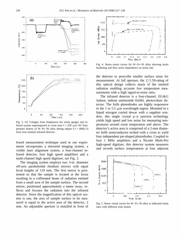
Fig. 4. Stress–strain curves for W–Fe–Ni alloy showing strainhardening and flow stress dependence on strain rate.
the detector to prescribe smaller surface areas formeasurement. At full aperture, the fr1.59-rating ofthis optical design collects much of the emittedradiation enabling accurate low temperature mea-surements with a high signal-to-noise ratio.
The infrared detector is a four-channel, EG&GŽ .Judson, indium antimonide InSb , photovoltaic de-
tector. The InSb photodiodes are highly responsivein the 1 to 5.5 mm wavelength region. Mounted in aliquid nitrogen cooled dewar with a sapphire win-dow, this single crystal p–n junction technologyyields high speed and low noise for measuring tem-peratures around room temperature and above. Thedetector’s active area is comprised of a 2-mm diame-ter InSb semiconductor etched with a cross to yieldfour independent pie-shaped photodiodes. Coupled tofour 1 MHz amplifiers and a Nicolet Multi-Prohigh-speed digitizer, this detector system measuresand records surface temperatures at four adjacent
Fig. 5. Stress–strain curves for W–Fe–Ni alloy at indicated strainrates with different total strains.

( )D.S. Kim et al.rMechanics of Materials 28 1998 227–236 231
Ž .Fig. 6. Micrographs of W–Fe–Ni alloy subjected to 50% strain in ´;5000rs .˙
areas in real time with 12 bit precision and a 1 msresolution. The detector is mounted to a translationstage with micrometer adjustments for final position-ing.
Alignment of this system is performed by illumi-nating the sample with a He–Ne laser and imagingthe resulting spot onto the detector element. Use ofmirrors, instead of lenses, allows visible light to beutilized for alignment of the infrared optics. By
maximizing the detector voltages with the fine ad-justments of the x–y translation stage, the detector ispositioned at the image focal point of the opticalsystem. A second laser beam intersects the alignmentbeam to indicate the object focal point allowingsamples to be repeatedly positioned for measure-ment.
Since the alignment of the optical system is al-tered by very slight disturbances, calibration is per-
Ž . Ž . Ž . Ž .Fig. 7. Micrographs of W–Fe–Ni alloy subjected to a 30% strain ´;3000rs and b 40% strain ´;4000rs .˙ ˙
( )D.S. Kim et al.rMechanics of Materials 28 1998 227–236232
formed immediately preceding the actual measure-ment. A thermocouple is attached to a cylindricalsample which is placed between the incident andtransmission bars of the split-Hopkinson pressure
apparatus. A soldering iron is used to heat the sam-ple to a temperature above the expected maximumvalue. After withdrawing the soldering iron, the volt-ages are recorded from the infrared detector electron-
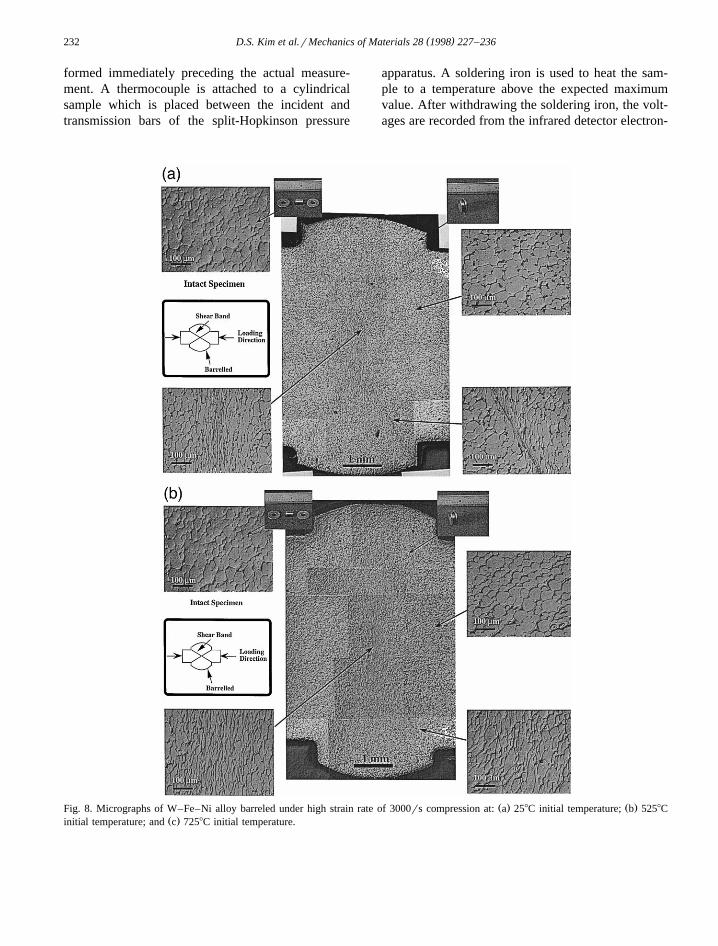
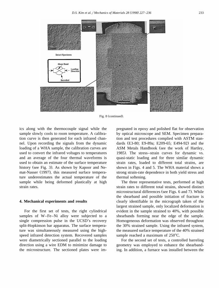
Ž . Ž .Fig. 8. Micrographs of W–Fe–Ni alloy barreled under high strain rate of 3000rs compression at: a 258C initial temperature; b 5258CŽ .initial temperature; and c 7258C initial temperature.
( )D.S. Kim et al.rMechanics of Materials 28 1998 227–236 233
Ž .Fig. 8 continued .
ics along with the thermocouple signal while thesample slowly cools to room temperature. A calibra-tion curve is then generated for each infrared chan-nel. Upon recording the signals from the dynamicloading of a WHA sample, the calibration curves areused to convert the infrared voltages to temperaturesand an average of the four thermal waveforms isused to obtain an estimate of the surface temperature
Ž .history see Fig. 3 . As shown by Kapoor and Ne-Ž .mat-Nasser 1997 , this measured surface tempera-
ture underestimates the actual temperature of thesample while being deformed plastically at highstrain rates.
4. Mechanical experiments and results
For the first set of tests, the right cylindricalsamples of W–Fe–Ni alloy were subjected to asingle compression pulse in the UCSD’s recoverysplit-Hopkinson bar apparatus. The surface tempera-ture was simultaneously measured using the high-speed infrared detection system. Recovered sampleswere diametrically sectioned parallel to the loadingdirection using a wire EDM to minimize damage tothe microstructure. The sectioned plates were im-
pregnated in epoxy and polished flat for observationby optical microscope and SEM. Specimen prepara-tion and test procedures complied with ASTM stan-
Ž .dards E3-80; E9-89a; E209-65; E494-92 and theŽASM Metals Handbook see the work of Hartley,
.1985 . The stress–strain curves for dynamic vs.quasi-static loading and for three similar dynamicstrain rates, loaded to different total strains, areshown in Figs. 4 and 5. The WHA material shows astrong strain-rate dependence in both yield stress andthermal softening.
The three representative tests, performed at highstrain rates to different total strains, showed distinct
Ž .microstructural differences see Figs. 6 and 7 . Whilethe shearband and possible initiation of fracture isclearly identifiable in the micrograph taken of thelargest strained sample, only localized deformation isevident in the sample strained to 40%, with possibleshearbands forming near the edge of the sample.Homogeneous deformation was observed throughoutthe 30% strained sample. Using the infrared system,the measured surface temperature of the 40% strainedsample reached a maximum of 2508C.
For the second set of tests, a controlled barrelinggeometry was employed to enhance the shearband-ing. In addition, a furnace was installed between the
( )D.S. Kim et al.rMechanics of Materials 28 1998 227–236234
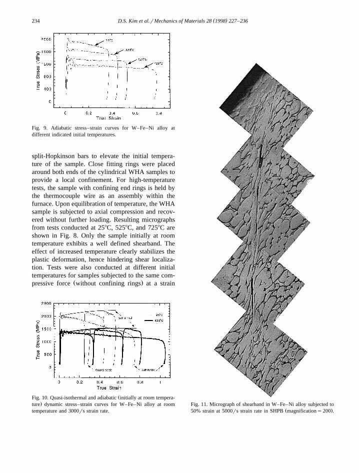
Fig. 9. Adiabatic stress–strain curves for W–Fe–Ni alloy atdifferent indicated initial temperatures.
split-Hopkinson bars to elevate the initial tempera-ture of the sample. Close fitting rings were placedaround both ends of the cylindrical WHA samples toprovide a local confinement. For high-temperaturetests, the sample with confining end rings is held bythe thermocouple wire as an assembly within thefurnace. Upon equilibration of temperature, the WHAsample is subjected to axial compression and recov-ered without further loading. Resulting micrographsfrom tests conducted at 258C, 5258C, and 7258C areshown in Fig. 8. Only the sample initially at roomtemperature exhibits a well defined shearband. Theeffect of increased temperature clearly stabilizes theplastic deformation, hence hindering shear localiza-tion. Tests were also conducted at different initialtemperatures for samples subjected to the same com-
Ž .pressive force without confining rings at a strain
ŽFig. 10. Quasi-isothermal and adiabatic initially at room tempera-.ture dynamic stress–strain curves for W–Fe–Ni alloy at room
temperature and 3000rs strain rate.Fig. 11. Micrograph of shearband in W–Fe–Ni alloy subjected to
Ž .50% strain at 5000rs strain rate in SHPB magnifications200 .
( )D.S. Kim et al.rMechanics of Materials 28 1998 227–236 235
rate of about 3000rs. The stress–strain curves inFig. 9 exhibit a lower flow stress and lower thermalsoftening because of the higher initial sample tem-perature.
High-strain-rate, quasi-isothermal stress–straincurves were generated for this material using thetechnique of successive compression pulses at room
Žtemperature as well as elevated temperature see Fig..10 . By allowing the WHA sample to cool to its
initial temperature between multiple deformations inthe compression Hopkinson bar, an isothermalstress–strain curve is obtained by combining the
Žincremental room temperature tests Nemat-Nasser.and Isaacs, 1997 . The resulting curves are nearly
identical to the quasi-static stress–strain curve shiftedhigher in flow stress for higher strain rate. Compari-
Žson between the isothermal the envelope of the.three curves and the adiabatic stress–strain curves
in this figure reveals the extent of the thermal soften-ing for this material.
5. Summary
Using different experimental techniques devel-oped at CEAM of UCSD, the strain, strain-rate, andtemperature effects on the flow stress of 93W–4.9Ni–2.1Fe heavy alloy were separated and quanti-fied. Based on quasi-isothermal flow stress at highstrain rates and isothermal flow stress at low strainrates, it is shown that over the range of strain ratesfrom 10y3 to 5=103rs, the strain hardening of thismaterial remains essentially the same, as long as thesample is deforming uniformly. Hence, the strainhardening can be evaluated using a simple quasi-static
Ž y3 .test e.g., at 10 rs strain rate .By direct comparison between the high-strain-rate
quasi-isothermal flow stress and the correspondingŽ .adiabatic values see Fig. 10 , the effect of tempera-
ture on the flow stress is quantified. Results of thiskind are used to obtain explicit expressions for the
wtemperature dependence of the flow stress see theŽ .works of Nemat-Nasser et al. 1994 ; Nemat-Nasser
Ž . Ž .xand Isaacs 1997 ; Nemat-Nasser and Li 1998 .Since tungsten is a bcc material, while fcc alloyscomprise the WHA matrix, more of the strain-rateand temperature sensitivity of this material is at-tributed to the large tungsten particles. Owing to itsgreater flow stress and low heat capacity, once the
tungsten begins to deform inelastically, it quicklyheats up, making it easier to participate in the overalldeformation of the localized deformation bands. Aclose-up of the shearband shown earlier reveals se-vere deformation of the tungsten grains within the
Ž .strain-localized zones see Fig. 11 . The shearbandformation in the sample deformed in a compressionHopkinson bar, was facilitated by constraining theends of the cylindrical sample with confinementrings. This simple procedure promotes barreling,causing intense localized deformations. High-strain-rate experiments performed at 258, 3258, 5258, and7258C initial temperatures clearly reveal the influ-ence of the temperature in suppressing the formationof shearbands. This simple technique, therefore, canbe used to study the propensity to shearbanding of agiven material and the influence of temperature onthis phenomenon.
Acknowledgements
This work has been supported by the US ArmyResearch Office under contracts No. DAAL03-86-K-0169 and No. DAAL03-92-G-0108 with the Univer-sity of California, San Diego. The authors appreciatethe valuable assistance of Mr. Brian Sonnichsen.
References
Clifton, R.J., Duffy, J., Hartley, K.A., Shawki, T.G., 1984. Oncritical conditions for shear band formation at high strain rates.Scripta Metallurgica 18, 443.
Hartley, K.A., 1985. ASM Metals Handbook, Vol. 8. Compiledby ASM International, Materials Park.
Kapoor, R., Nemat-Nasser, S., 1997. Determination of tempera-ture rise during the high strain rate deformation. Mech. Mater.,accepted 10r97.
Keckes, L.J., Hall, I.W., 1992. Hot explosive consolidation ofW–Ti alloys. Proceedings of Int. Symp. Tungsten and Tung-sten Alloys—1992. Washington, DC, November, 155.
Kolsky, H., 1949. An investigation of the mechanical properties ofmaterials at very high strain rates of loading. Proc. R. Soc.London 62B, 676.
Lankford, J., Bose, A., Couque, H., 1992. High strain-rate behav-ior of tungsten heavy alloys, High Strain Rate Behavior ofRefractory Metals and Alloys. Miner. Met. Mater. Soc., pp.267–287.
Magness, L.S., Farrand, T.G., 1990. Deformation behavior and itsrelationship to the penetration performance of high-density KE

( )D.S. Kim et al.rMechanics of Materials 28 1998 227–236236
Ž .penetrator materials. Army Sci. Conf: Proc. 17 , Durham,NC.
Meyers, M.A., Chen, Y.-J., Marquis, F.D.S., Kim, D.S., 1995.High-strain, high-strain rate behavior of tantalum. Met. Trans.
Ž .A 26A 10 , 2493.Nemat-Nasser, S., Isaacs, J., 1997. Direct measurement of isother-
mal flow stress of metal at elevated temperatures and highstrain rates. Acta Met. 45, 907.
Nemat-Nasser, S., Li, Y., 1998. Flow stress of FCC polycrystalsŽ .with application to OFHC copper. Acta Materialia 46 2 ,
565–577.Nemat-Nasser, S., Isaacs, J.B., Starrett, J.E., 1991. Hopkinson
techniques for dynamic recovery experiments. Proc. R. Soc.London A 135, 371.
N em at-N asser, S., L i, Y .-F., Isaacs, J.B ., 1994.Experimentalrcomputational evaluation of flow stress at highstrain rates with application to adiabatic shear banding. Mech.Mater. 17, 111.
Ramesh, K.T., Coates, R.S., 1992. Microstructural influences onthe dynamic response of tungsten heavy alloys. Met. Trans. A23A, 2625–2630.
Taylor, G.I., Quinney, H., 1934. The latent energy remaining in ametal after cold working. Proc. R. Soc. London A 1–3, 307.
Zener, C., Hollomon, J.H., 1944. Effect of strain rate upon plasticŽ .flow of steel. J. Appl. Phys. 15 1 , 22.