additive manufactured product integrity - nasa€¦ · thrust chamber assembly and injector...
TRANSCRIPT

Additive Manufactured Product
IntegrityJess Waller NASA WSTF
Doug Wells NASA MSFC
Steve James Aerojet Rocketdyne
Charles Nichols NASA WSTF
Quality Leadership Forum
March 15 & 16, 2017
Cape Canaveral, FL
1:30 - 2:00 PM, Wednesday, March 15, 2017
https://ntrs.nasa.gov/search.jsp?R=20170002071 2020-05-01T15:39:40+00:00Z

Background
2
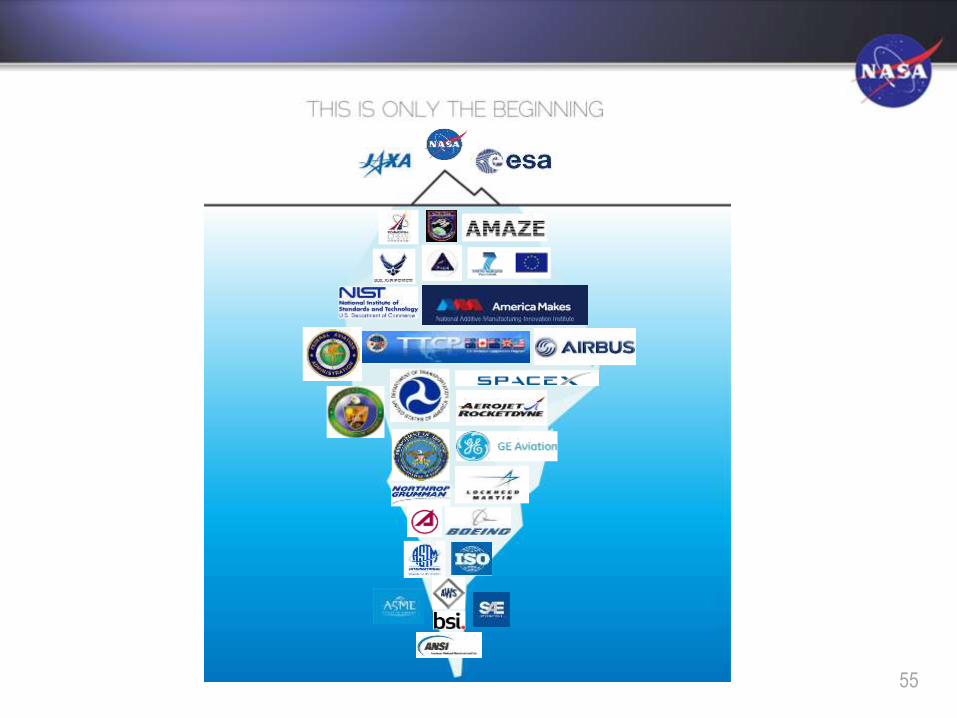
• NASA is providing leadership in an international effort linking government and industry resources to speed adoption of NDT of additive manufactured (AM) parts to meet the industry needs
• Participants include government agencies (NASA, USAF, NIST, FAA), industry (commercial aerospace, NDE manufacturers, AM equipment manufacturers), standards organizations and academia
• NASA is also partnering with its international space exploration organizations such as ESA and JAXA
• NDT is identified as a universal need for all aspects of additive manufacturing
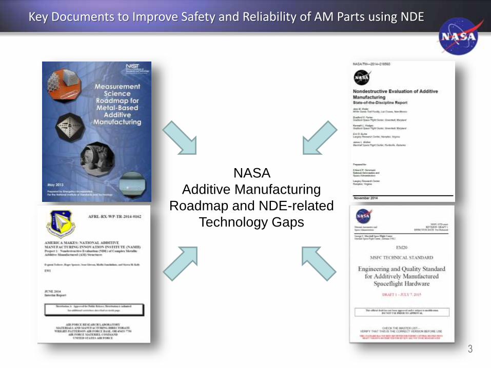
Key Documents to Improve Safety and Reliability of AM Parts using NDE
3
NASA
Additive Manufacturing
Roadmap and NDE-related
Technology Gaps

Background
NASA/TM-2014-218560 NDE of AM State-of-the-Discipline Report
Contacts: Jess Waller (WSTF); James
Walker (MSFC); Eric Burke (LaRC);
Ken Hodges (MAF); Brad Parker
(GSFC)• NASA Agency additive
manufacturing efforts were
catalogued
• Industry, government and academia
were asked to share their NDE
experience in additive manufacturing
• NIST and USAF additive
manufacturing roadmaps were
surveyed and a technology gap
analysis performed
• NDE state-of-the-art was documented
4

NASA Agency & Prime Contractor Activity, ca. 2014
Reentrant Ti6-4 tube for a
cryogenic thermal switch for the
ASTRO-H Adiabatic
Demagnetization Refrigerator
Inconel Pogo-Z baffle for RS-25
engine for SLS
Aerojet Rocketdyne RL-10 engine
thrust chamber assembly and injector
Prototype titanium to niobium gradient rocket nozzle
EBF3 wire-fed system during
parabolic fight testing
5
28-element Inconel 625 fuel
injector
SpaceX SuperDraco combustion
chamber for Dragon V2ISRU regolith structures
Made in Space AMF on ISS
Dynetics/Aerojet Rocketdyne
F-1B gas generator injector

6
Additive Manufacturing
Technology Gap Analysis

NASA/TM-2014-218560 Recommendations & Technology Gap Analysis
7
NDE of AM Technology Gaps• Develop in-situ monitoring to improve feedback control, maximize
part quality and consistency, and obtain ready-for-use certified parts
• Develop and refine NDE of as-built and post-processed AM parts
• Develop voluntary consensus standards for NDE of AM parts
• Develop better physics-based process models using and corroborated
by NDE
• Use NDE to understand scatter in design allowables database
generation activities (process-structure-property correlation)
• Fabricate AM physical reference samples to demonstrate NDE
capability for specific defect types
• Apply NDE to understand effect-of-defect, and establish acceptance
limits for specific defect types and defect sizes
• Develop NDE-based qualification and certification protocols for flight
hardware (screen out critical defects)
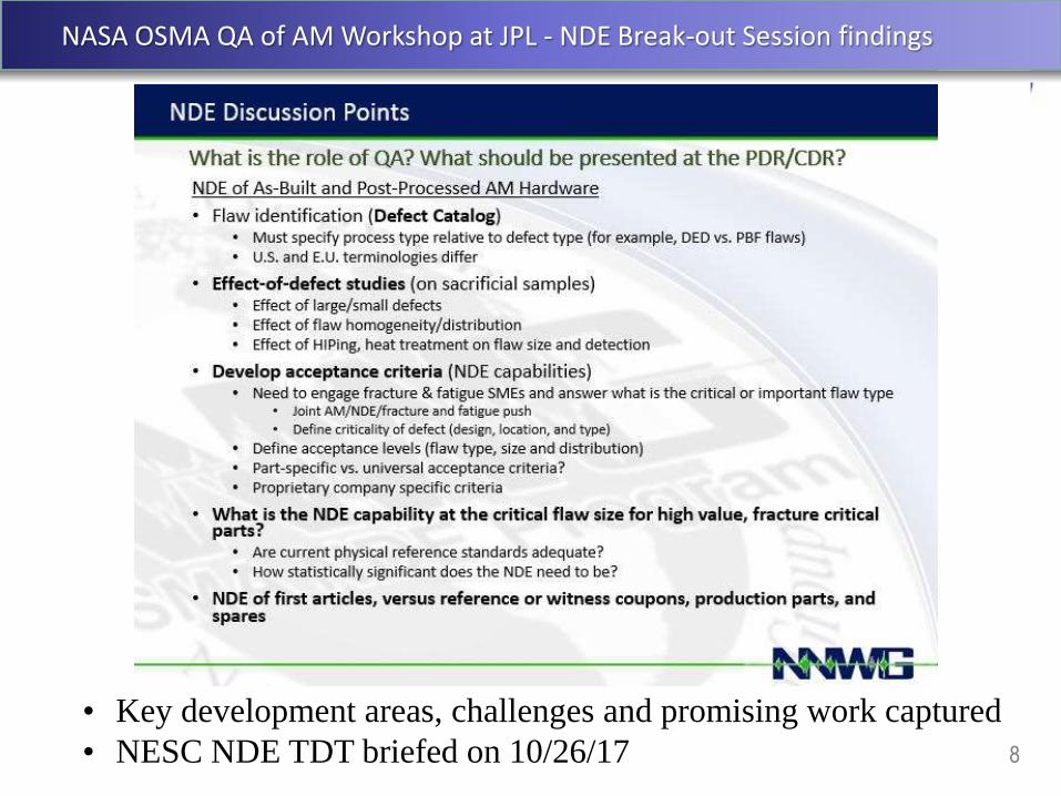
NASA OSMA QA of AM Workshop at JPL - NDE Break-out Session findings
8
• Key development areas, challenges and promising work captured
• NESC NDE TDT briefed on 10/26/17

9
Identify Relevant AM Defects

10
NDE of AM Technology Gaps
NASA/TM-2014-218560 Recommendations & Technology Gap Analysis
• Develop/generate an AM defects catalogue
• Develop in-process NDE to improve feedback control, maximize part
quality and consistency, and obtain ready-for-use certified parts
• Develop post-process NDE of finished parts
• Develop voluntary consensus standards for NDE of AM parts
• Develop better physics-based process models using and corroborated
by NDE
• Use NDE to understand scatter in design allowables database
generation activities (process-structure-property correlation)
• Fabricate AM physical reference samples to demonstrate NDE
capability for specific defect types
• Apply NDE to understand effect-of-defect, and establish acceptance
limits for specific defect types and defect sizes
• Develop NDE-based qualification and certification protocols for flight
hardware (screen out critical defects)
NEW gap identified
18
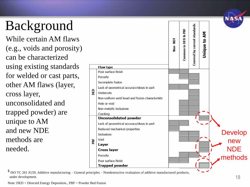
Background
§ISO TC 261 JG59, Additive manufacturing – General principles – Nondestructive evaluation of additive manufactured products,
under development.
Note: DED = Directed Energy Deposition., PBF = Powder Bed Fusion
Develop
new
NDE
methods
While certain AM flaws
(e.g., voids and porosity)
can be characterized
using existing standards
for welded or cast parts,
other AM flaws (layer,
cross layer,
unconsolidated and
trapped powder) are
unique to AM
and new NDE
methods are
needed.

12
Typical PBF Defects of Interest
Also have unconsolidated powder, lack of geometrical accuracy/steps
in the part, reduced mechanical properties, inclusions, gas porosity,
voids, and poor or rough surface finish
Trapped PowderLayer
Cross layer

13
Typical PBF and DED Defects
DED Porosity
Also interested in (gas) porosity and voids due to structural implications
PBF Porosity
Note: proposed new definitions in ISO/ASTM 52900 Terminology:lack of fusion (LOF) nflaws caused by incomplete melting and cohesion between the deposited metal and previously deposited metal.
gas porosity, nflaws formed during processing or subsequent post-processing that remain in the metal after it has cooled. Gas porosity occurs because most metals have dissolved gas in the
melt which comes out of solution upon cooling to form empty pockets in the solidified material. Gas porosity on the surface can interfere with or preclude certain NDT methods, while porosity
inside the part reduces strength in its vicinity. Like voids, gas porosity causes a part to be less than fully dense.
voids, n flaws created during the build process that are empty or filled with partially or wholly un-sintered or un-fused powder or wire creating pockets. Voids are distinct from gas porosity,
and are the result of lack of fusion and skipped layers parallel or perpendicular to the build direction. Voids occurring at a sufficient quantity, size and distribution inside a part can reduce its
strength in their vicinity. Voids are also distinct from intentionally added open cells that reduce weight. Like gas porosity, voids cause a part to be less than fully dense.
Voids
Univ of Louisville
ConceptLaser
Plastic
Porosity and Voids
SLM Solutions
ISO TC 261 ISO TC 261

14
Develop and Capture
Best NDE Practice

Round Robin Test Goals
NASA/TM-2014-218560 Recommendations & Gap Analysis
• Develop in-situ monitoring to improve feedback control, maximize
part quality and consistency, and obtain ready-for-use certified parts
• Develop and refine NDE of as-built and post-processed AM parts
• Develop voluntary consensus standards for NDE of AM parts
• Develop better physics-based process models using and corroborated
by NDE
• Use NDE to understand scatter in design allowables database
generation activities (process-structure-property correlation)
• Fabricate AM physical reference samples to demonstrate NDE
capability for specific defect types
• Apply NDE to understand effect-of-defect, and establish acceptance
limits for specific defect types and defect sizes
• Develop NDE-based qualification and certification protocols for flight
hardware (screen out critical defects)66

16
Effect of Design Complexity on NDE
Contact: Evgueni Todorov (EWI)• Great initial handling of NDE of
AM parts
• Report has a ranking system
based on geometric complexity
of AM parts to direct NDE
efforts
• Early results on NDE application
to AM are documented
• Approach for future work based
on CT and PCRT

17
Effect of AM Part Complexity on NDEMost NDE techniques can be used for Complexity Groups§ 1 (Simple Tools and Components) and 2 (Optimized Standard Parts), some for Group 3 (Embedded Features); only Process Compensated Resonance Testing and Computed Tomography can be used for Groups 4 (Design-to-Constraint Parts) and 5 (Free-Form Lattice Structures):
1 2 3
4 5
§Kerbrat, O., Mognol, P., Hascoet, J. Y., Manufacturing Complexity Evaluation for Additive and Subtractive Processes: Application to Hybrid Modular
Tooling, IRCCyN, Nantes, France, pp. 519-530, September 10, 2008.

18
Background
§Kerbrat, O., Mognol, P., Hascoet, J. Y., Manufacturing Complexity Evaluation for Additive and Subtractive Processes: Application
to Hybrid Modular Tooling, IRCCyN, Nantes, France, pp. 519-530, September 10, 2008.
NDE options for
design-to-constraint
parts and lattice
structures: LT,
PCRT and CT/mCT
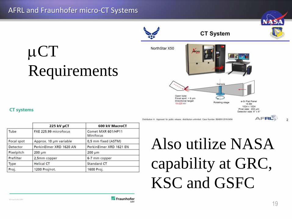
AFRL and Fraunhofer micro-CT Systems
19
mCT
Requirements
Also utilize NASA
capability at GRC,
KSC and GSFC

20
Process Compensated Resonance Testing
PCRT also can distinguish processing effects, for example, SLM samples made with different
laser scanning speeds (Ti6-4 Gong/Univ. of Louisville samples)

21
Nonlinear Resonant Ultrasonic Testing (RUS)
TRL4 system available with
advanced software
• Frequency scan at more than more amplitude
• Shows promise for detection of initial defects
before catastrophic failure
• Signal not affected by part size or geometry
• MSFC to supply samples to LANL

22
Coordinated by S. James (Aerojet Rocketdyne)
NASA LaRC
Inconel 625 on copper
Ti-6Al-4V (4)
Electron Beam Freeform
Fabrication (EBF3)
SS 316
Al 2216
Laser-PBF
(L-PBF)Gong
Ti-6Al-4V barsAirbus
Al-Si-10Mg dog bonesMet-L-Check
SS 316 PT/RT panels
w/ EDM notches
Electron Beam-PBF
(E-PBF)
Concept Laser Inconel 718 inserts (6)
w/ different processing history
Concept Laser Inconel 718 prisms
for CT capability demonstrationCharacterized to date
by various NDE
techniques (CT, RT,
PT, PCRT, UT)
ASTM WK47031 Round Robin Testing (Leveraged)
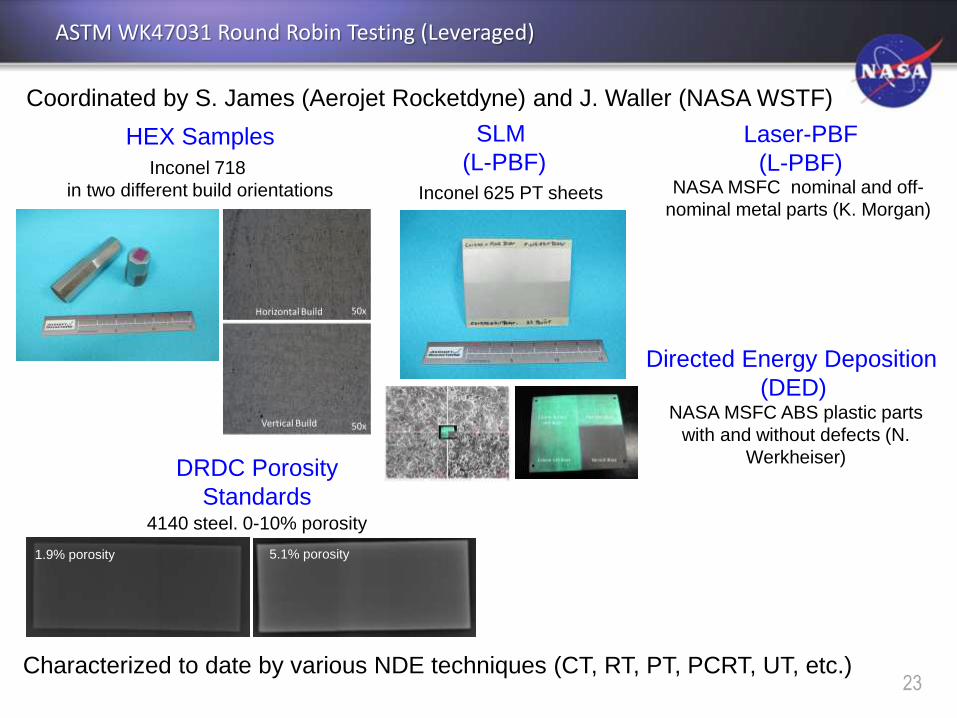
Characterized to date by various NDE techniques (CT, RT, PT, PCRT, UT, etc.)23
Inconel 718
in two different build orientations
HEX Samples Laser-PBF
(L-PBF)
Directed Energy Deposition
(DED)
NASA MSFC nominal and off-
nominal metal parts (K. Morgan)
NASA MSFC ABS plastic parts
with and without defects (N.
Werkheiser)
Inconel 625 PT sheets
SLM
(L-PBF)
DRDC Porosity
Standards4140 steel. 0-10% porosity
1.9% porosity 5.1% porosity
Coordinated by S. James (Aerojet Rocketdyne) and J. Waller (NASA WSTF)
ASTM WK47031 Round Robin Testing (Leveraged)

ASTM E07.10 WK47031 Round Robin Testing - Illustrative
24
Round Robin Sample Activity – illustrative presentations

ASTM E07.10 WK47031 Round Robin Testing Online Collaboration Area
25
Working drafts and minutes of webmeetings discussing the
standard Guide for NDE of AM aerospace parts are posted on-line:

26
CT/MET, MSFC/James Walker
*metal SLM parts, MSFC/Kristin Morgan
*ABS plastic parts, MSFC/Niki Werkheiser
CT, GSFC/Justin Jones
*EBF3 metal parts, LaRC/Karen Taminger
POD/fracture critical AM parts, ESA/Gerben Sinnema
AE, MRI/Ed Ginzel
CT/acoustic microscopy, Honeywell/Surendra Singh
UT/PT, Aerospace Rocketdyne/Steve James
CT/RT, USAF/John Brausch, Ken LaCivita
CT, Fraunhofer/Christian Kretzer
CT, GE Sensing GmbH/Thomas Mayer
PCRT, Vibrant Corporation/Eric Biedermann
PT, Met-L-Check/Mike White
Nonlinear RUS, LANL/Marcel Remillieux
*Concept Laser/Marie Ebert
*DRDC/Shannon Farrell
†*Airbus/Amy Glover
†*UTC/John Middendorf, Wright State University/Greg Loughnane
†*CalRAM/Shane Collins
* delivered or committed to deliver samples
† E8 compliant sacrificial dogbone samples
NASA
Commercial/Gov NDE
Commercial/Gov
AM Round Robin
Sample Suppliers

27
Voluntary Consensus Standards
Gap Analysis
28
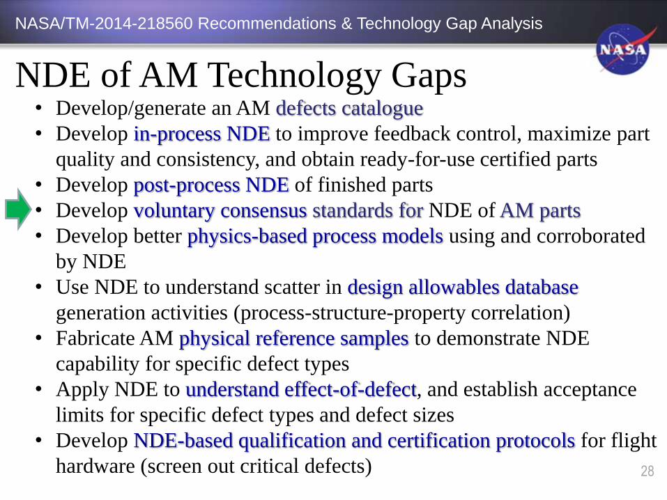
NDE of AM Technology Gaps
NASA/TM-2014-218560 Recommendations & Technology Gap Analysis
• Develop/generate an AM defects catalogue
• Develop in-process NDE to improve feedback control, maximize part
quality and consistency, and obtain ready-for-use certified parts
• Develop post-process NDE of finished parts
• Develop voluntary consensus standards for NDE of AM parts
• Develop better physics-based process models using and corroborated
by NDE
• Use NDE to understand scatter in design allowables database
generation activities (process-structure-property correlation)
• Fabricate AM physical reference samples to demonstrate NDE
capability for specific defect types
• Apply NDE to understand effect-of-defect, and establish acceptance
limits for specific defect types and defect sizes
• Develop NDE-based qualification and certification protocols for flight
hardware (screen out critical defects)
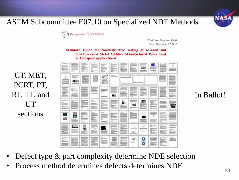
ASTM Subcommittee E07.10 on Specialized NDT Methods
• Defect type & part complexity determine NDE selection
• Process method determines defects determines NDE
In Ballot!
29
CT, MET,
PCRT, PT,
RT, TT, and
UT
sections

WK47031 Collaboration Area Membership
30
65 current membersNASA, JAXA, ESA, NIST, USAF, GE Aviation, Aerojet
Rocketdyne, Lockheed, Honeywell, Boeing, Aerospace Corp,
ULA, academia and various AM and NDE community
participants are represented
(48 current members as of June ASTM E07 Committee on NDT meeting)
31
ANSI-America Makes
National Collaborative Effort:
Proposed New AM Standards
Additive Manufacturing Standards Collaborative (AMSC) Recommendations

America Makes & ANSI AMSC Findings
• 181 members (early June)
• Walker, Wells, Luna and Waller among NASA-affiliated members on roster
• Industry Review of Roadmap - December 14, 2016
• Comments being reviewed now by appropriate WGs
• The roadmap will be published by the end of February 2017
• 89 standards gaps identified
o 6 nondestructive evaluation gaps
o 15 qualification and certification gaps
o 6 precursor materials gaps
o 17 process control gaps
o 5 post-processing gaps
o 5 finished materials gaps
o 26 design gaps
o 8 maintenance gaps
• Future meetings of Standards Development Organizations will discuss how the
standards are divvied up
32

America Makes & ANSI Additive Manufacturing Standardization Collaborative (AMSC)
• America Makes and ANSI Launch Additive Manufacturing Standardization
Collaborative; Kick-off Meeting held March 31, 2016
• 5 Working Groups established to cover AM standards areas
33

America Makes & ANSI AMSC Working Groups
• 5 Working Groups established to cover AM standards areas(cont.)
34

America Makes & ANSI AMSC Working Groups
• 5 Working Groups established to cover AM standards areas(cont.)
35

61
Gaps Identified by NDE Working Group
E07 - WK47031
F42 - WK56649
AMSC NDT of AM Standards Gaps
Standards in progress

Balloting begun
(CT, MET, PCRT, PT, RT,
TT, and UT)
Current and future NDE of AM standards under development (ASTM)
37
Motion to register as a
formal work item
approved by E07.10
(IR, LUT, VIS)
Draft in Preparation
E07
F42
E07
POC: J. Waller
POC: S. James
POC: S. Singh
E07
E07?
POC: TBD
POC: TBD
Future
Future, phys ref stds
to demonstrate
NDE capability
Future Standards for NDT of AM Aerospace Materials
38
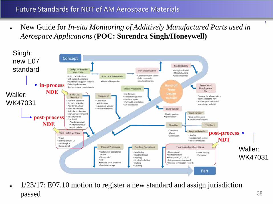
New Guide for In-situ Monitoring of Additively Manufactured Parts used in
Aerospace Applications (POC: Surendra Singh/Honeywell)
1/23/17: E07.10 motion to register a new standard and assign jurisdiction
passed
Waller:
WK47031
Waller:
WK47031
Singh:
new E07
standard

39
Demonstrate NDE Capability

40
NDE of AM Technology Gaps
NASA/TM-2014-218560 Recommendations & Technology Gap Analysis
• Develop/generate an AM defects catalogue
• Develop in-process NDE to improve feedback control, maximize part
quality and consistency, and obtain ready-for-use certified parts
• Develop post-process NDE of finished parts
• Develop voluntary consensus standards for NDE of AM parts
• Develop better physics-based process models using and corroborated
by NDE
• Use NDE to understand scatter in design allowables database
generation activities (process-structure-property correlation)
• Fabricate AM physical reference samples to demonstrate NDE
capability for specific defect types
• Apply NDE to understand effect-of-defect, and establish acceptance
limits for specific defect types and defect sizes
• Develop NDE-based qualification and certification protocols for flight
hardware (screen out critical defects)
(NEW)

41
Demonstrate NDE capability
Actual and Planned NASA Physical Reference Samples for Additive Manufacturing
42
Understand Effect-of-Defect

43
NDE of AM Technology Gaps
NASA/TM-2014-218560 Recommendations & Technology Gap Analysis
• Develop/generate an AM defects catalogue
• Develop in-process NDE to improve feedback control, maximize part
quality and consistency, and obtain ready-for-use certified parts
• Develop post-process NDE of finished parts
• Develop voluntary consensus standards for NDE of AM parts
• Develop better physics-based process models using and corroborated
by NDE
• Use NDE to understand scatter in design allowables database
generation activities (process-structure-property correlation)
• Fabricate AM physical reference samples to demonstrate NDE
capability for specific defect types
• Apply NDE to understand effect-of-defect, and establish acceptance
limits for specific defect types and defect sizes
• Develop NDE-based qualification and certification protocols for flight
hardware (screen out critical defects)
(NEW)

44
Approach Determine effect-of-defect on sacrificial specimens w/ seeded flaws
Sacrificial Effect-of-Defect Samples
2. UTC Laser PBF samples
Ti-6Al-4V ASTM E8 compliant dogbones for in situ OM/IR
and post-process profilometry, CT and PCRT
AlSi10Mg ASTM E8 compliant dogbones
13mmØ, 85mm long (6mmØ, 30mm Gauge Length)
1. Airbus Laser PBF samples
Investigate effect post-processing on
microstructure and surface finish on
fatigue properties
CT at GRC as of November
Other NDE planned in ASTM NDT Taskgroup
Airbus study on effect of process parameters on final properties

45
Parallel effortDetermine effect-of-defect on sacrificial specimens w/ seeded flaws
Sacrificial Effect-of-Defect Samples
America Makes Ed Morris (VP) call to fabricate samples for NDE
in support of ASTM WK47031 effort
Insert 1 “Lower Laser Power” Insert 4 “Trace Width Bigger”
3. CalRAM Electron Beam PBF samples
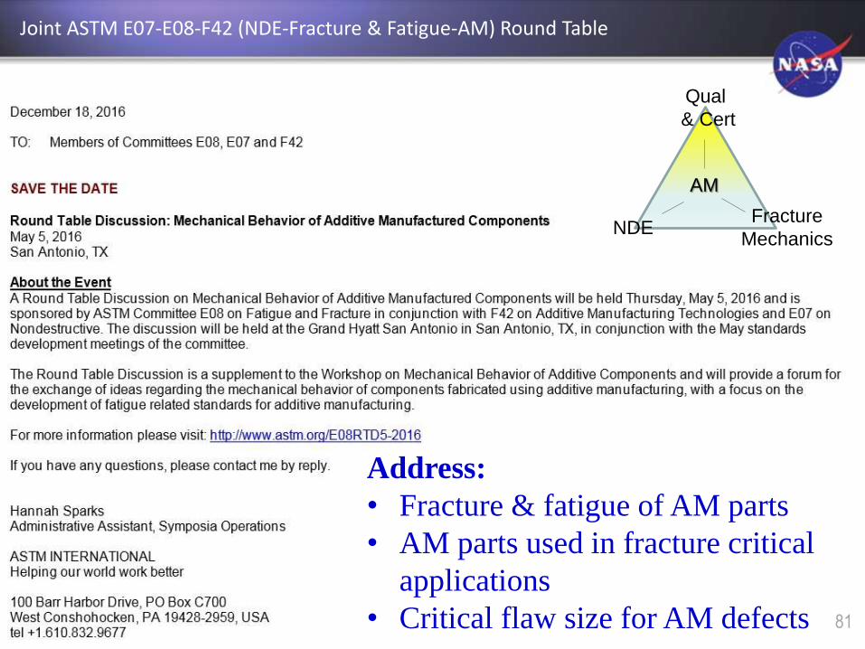
Joint ASTM E07-E08-F42 (NDE-Fracture & Fatigue-AM) Round Table
Address:
• Fracture & fatigue of AM parts
• AM parts used in fracture critical
applications
• Critical flaw size for AM defects
Qual
& Cert
Fracture
MechanicsNDE
AM
81

47
Qualify & Certify AM
Spaceflight Hardware

48
NDE of AM Technology Gaps
NASA/TM-2014-218560 Recommendations & Technology Gap Analysis
• Develop/generate an AM defects catalogue
• Develop in-process NDE to improve feedback control, maximize part
quality and consistency, and obtain ready-for-use certified parts
• Develop post-process NDE of finished parts
• Develop voluntary consensus standards for NDE of AM parts
• Develop better physics-based process models using and corroborated
by NDE
• Use NDE to understand scatter in design allowables database
generation activities (process-structure-property correlation)
• Fabricate AM physical reference samples to demonstrate NDE
capability for specific defect types
• Apply NDE to understand effect-of-defect, and establish acceptance
limits for specific defect types and defect sizes
• Develop NDE-based qualification and certification protocols for flight
hardware (screen out critical defects)
(NEW)
49
Background
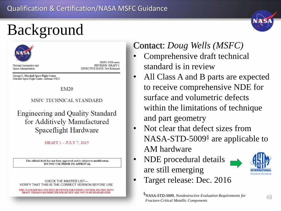
Qualification & Certification/NASA MSFC Guidance
Contact: Doug Wells (MSFC)• Comprehensive draft technical
standard is in review
• All Class A and B parts are expected
to receive comprehensive NDE for
surface and volumetric defects
within the limitations of technique
and part geometry
• Not clear that defect sizes from
NASA-STD-5009§ are applicable to
AM hardware
• NDE procedural details
are still emerging
• Target release: Dec. 2016
§NASA-STD-5009, Nondestructive Evaluation Requirements for
Fracture-Critical Metallic Components

Aspects of MSFC AM Process Control
50
Part
Process
Control
Build Vendor
Process
Control
Equipment
Process
Control
Metallurgical
Process
Control
Draft NASA MSFC Standard implements four
fundamental aspects of process control for AM:
• Each aspect of process control has an essential role in the
qualification of AM processes and parts and certification of the
systems in which they operate.
• The standard provides a consistent framework for these
controls and provides a consistent set of review/audit products

Overview of MSFC AM Standard
51

Products of the MSFC AM Standard
52
PDP = Part Development Plans (Overview and implementation)
• Communication, convey risk
• Classification and rationale
DVS = Design Value Suite (properties database)
• “Allowables,” integrated through PCRDs
QMP = Qualified Metallurgical Process (foundational control)
• Analogous to a very detailed weld PQR
PCRD = Process Control Reference Distribution
• Defined reference state to judge process consistency
FAI = First Article Inspection
MRR = Manufacturing Readiness Review
QPP = Qualified Part Process
• Finalized “frozen” part process
ECP = Equipment Control Plans
• Machine qual, re-qual, maintenance, contamination control
QMS = Quality Management System
• Required at AS9100 level with associated audits
53
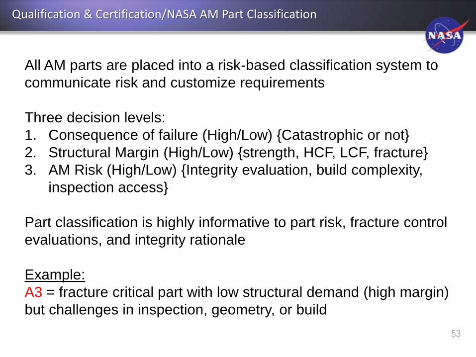
Qualification & Certification/NASA AM Part Classification
All AM parts are placed into a risk-based classification system to
communicate risk and customize requirements
Three decision levels:
1. Consequence of failure (High/Low) {Catastrophic or not}
2. Structural Margin (High/Low) {strength, HCF, LCF, fracture}
3. AM Risk (High/Low) {Integrity evaluation, build complexity,
inspection access}
Part classification is highly informative to part risk, fracture control
evaluations, and integrity rationale
Example:
A3 = fracture critical part with low structural demand (high margin)
but challenges in inspection, geometry, or build

54
Background
Qualification & Certification/NASA AM Part Classification
§ NASA classifications should not to be confused with those used in the ASTM International standards for AM parts, such as F3055
Standard Specification for Additive Manufacturing Nickel Alloy (UNS N07718) with Powder Bed Fusion. The ASTM classes are
used to represent part processing only and are unrelated.
Comprehensive
NDE required
for surface and
volumetric
defects
55

Back-ups

AMSC NDT of AM standards gaps
• Led by Patrick Howard, GE Aviation
• 28 members drawn from aerospace, automotive and medical industries
• Mapping started May 2016 – September2016
– One Face-to-face meeting
• Met bi-weekly – Web meeting
– Hosted by ANSI
– 6 to 8 members participated
– Identified 6 Standardization Gaps
Gaps Identified by AMSC NDE Working Group:
57

58
Demonstrate NDE capability
Conceptual Physical Reference Samples
59
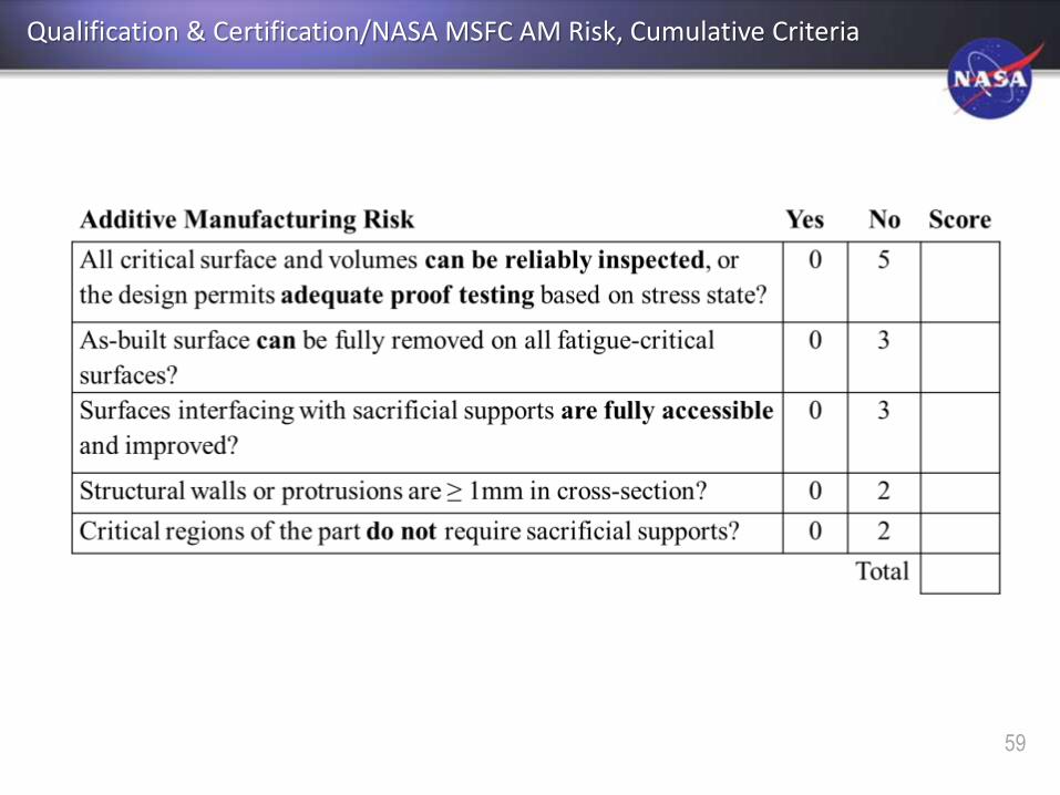
Qualification & Certification/NASA MSFC AM Risk, Cumulative Criteria
60
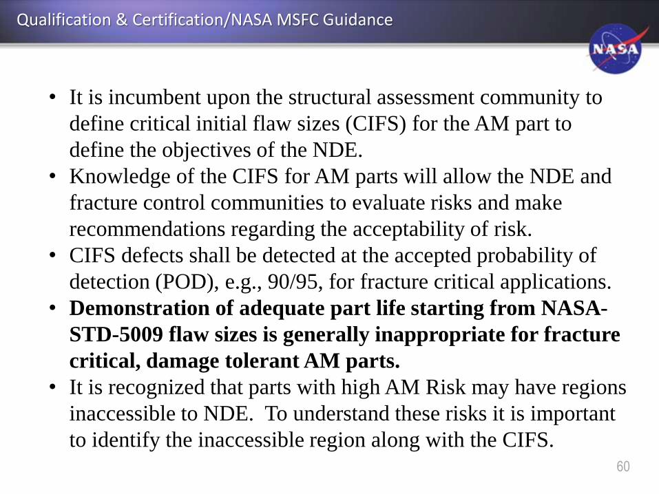
Qualification & Certification/NASA MSFC Guidance
• It is incumbent upon the structural assessment community to
define critical initial flaw sizes (CIFS) for the AM part to
define the objectives of the NDE.
• Knowledge of the CIFS for AM parts will allow the NDE and
fracture control communities to evaluate risks and make
recommendations regarding the acceptability of risk.
• CIFS defects shall be detected at the accepted probability of
detection (POD), e.g., 90/95, for fracture critical applications.
• Demonstration of adequate part life starting from NASA-
STD-5009 flaw sizes is generally inappropriate for fracture
critical, damage tolerant AM parts.
• It is recognized that parts with high AM Risk may have regions
inaccessible to NDE. To understand these risks it is important
to identify the inaccessible region along with the CIFS.
61
Qualification & Certification/NASA MSFC Guidance
• Parts with low AM risk should exhibit much greater coverage for
reliable NDE.
• Multiple NDE techniques may be required to achieve full coverage.
• Surface inspection techniques (PT, ECT, UT) may require the as-
built surface be improved to render a successful inspection,
depending upon the defect sizes of interest and the S/N ratio.
• For PT, surfaces improved using machining, for example, require
etching prior to inspection to remove smeared metal. • Removal of the as-built AM surface to a level of visually smooth may be insufficient
to reduce the NDE noise floor due to near-surface porosity and boundary artifacts.
• NDE demonstration parts with simulated CIFS defects are used to
demonstrate NDE detection capability.
• NDE standard defect classes for welds and castings welding or
casting defect quality standards will generally not be applicable

62
Qualification & Certification/NASA MSFC Guidance
• Relevant AM process defect types used must be considered.
• AM processes tend to prohibit volumetric defects with significant
height in the build (Z) direction. The concern instead is for planar
defects, such as aligned or chained porosity or even laminar cracks,
that form along the build plane. The implications of this are: − planar defects are well suited for growth
− planar defects generally have low contained volume
− the orientation of defects of concern must known before inspection,
especially when detection sensitivity depends on the defect orientation
relative to the inspection direction
− the Z-height of planar defects can be demanding on incremental step
inspection methods such as CT
• Until an AM defects catalog and associated NDE detection
limits for AM defects are established, NDE acceptance criteria
shall be for part-specific point designs.

Qualification & Certification/NASA AM Part Classification
Material Property Criteria for High Structural Margin
Loads Environment Well defined or bounded loads environment
Environmental Degradation Only due to temperature
Ultimate Strength 30% margin over factor of safety
Yield Strength 20% margin over factor of safety
Point Strain Local plastic strain < 0.005
High Cycle Fatigue, Improved
Surfaces
4x additional life factor or 20% below
required fatigue limit cyclic stress range
High Cycle Fatigue, As-built
Surfaces
10x additional life factor or 40% below
required fatigue limit cyclic stress range
Low Cycle Fatigue No predicted cyclic plastic strain
Fracture Mechanics Life 10x additional life factor
Creep Strain No predicted creep strain
Structural Margin Criteria
63

Qualification & Certification/Qualified Metallurgical Process
• Draft NASA MSFC Standard identifies AM as a unique
material product form and requires the metallurgical
process to be qualified on every individual AM machine
• Developed from internal process specifications with
likely incorporation of forthcoming industry standards.
Powder Process Variables Microstructure Properties
64

Qualification & Certification/Qualified Metallurgical Process
QMP:
• Feedstock control or
specification
• AM machine parameters,
configuration, environment
• As-built densification,
microstructure, and defect state
• Control of surface finish and
detail rendering
• Thermal process for controlled
microstructural evolution
• Mechanical behavior reference
data
– Strength, ductility, fatigue
performance
65

Qualification & Certification/Qualified Metallurgical Process
Qualified Metallurgical Process (QMP)
• As-built densification, microstructure, and defect state
• Thermal process for controlled microstructural evolution
HIP & FinalStress Relieved As Built
66
67
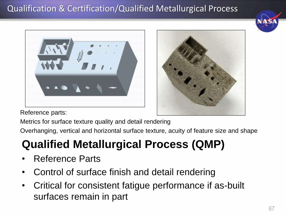
Qualified Metallurgical Process (QMP)
• Reference Parts
• Control of surface finish and detail rendering
• Critical for consistent fatigue performance if as-built
surfaces remain in part
Reference parts:
Metrics for surface texture quality and detail rendering
Overhanging, vertical and horizontal surface texture, acuity of feature size and shape
Qualification & Certification/Qualified Metallurgical Process

68
Qualification & Certification/Qualified Metallurgical Process
• Mechanical behavior reference data
– Strength, ductility, fatigue performance
– Process Control Reference Distributions (PCRD)
• Establish and document estimates of mean value and variation
associated with mechanical performance of the AM process
per the QMP
– May evolve with lot variability, etc.
• Utilize knowledge of process performance to establish
meaningful witness test acceptance criteria

Types of AM build witness specimens
• Metallurgical
• Tensile (strengths and ductility)
• Fatigue
• Low-margin, governing properties (as needed)
What is witnessed?
• Witness specimens provide direct evidence only for
the systemic health of the AM process during the
witnessed build
• Witness specimens are only an in-direct indicator of
AM part quality through inference.
Qualification & Certification/Qualified Metallurgical Process
69
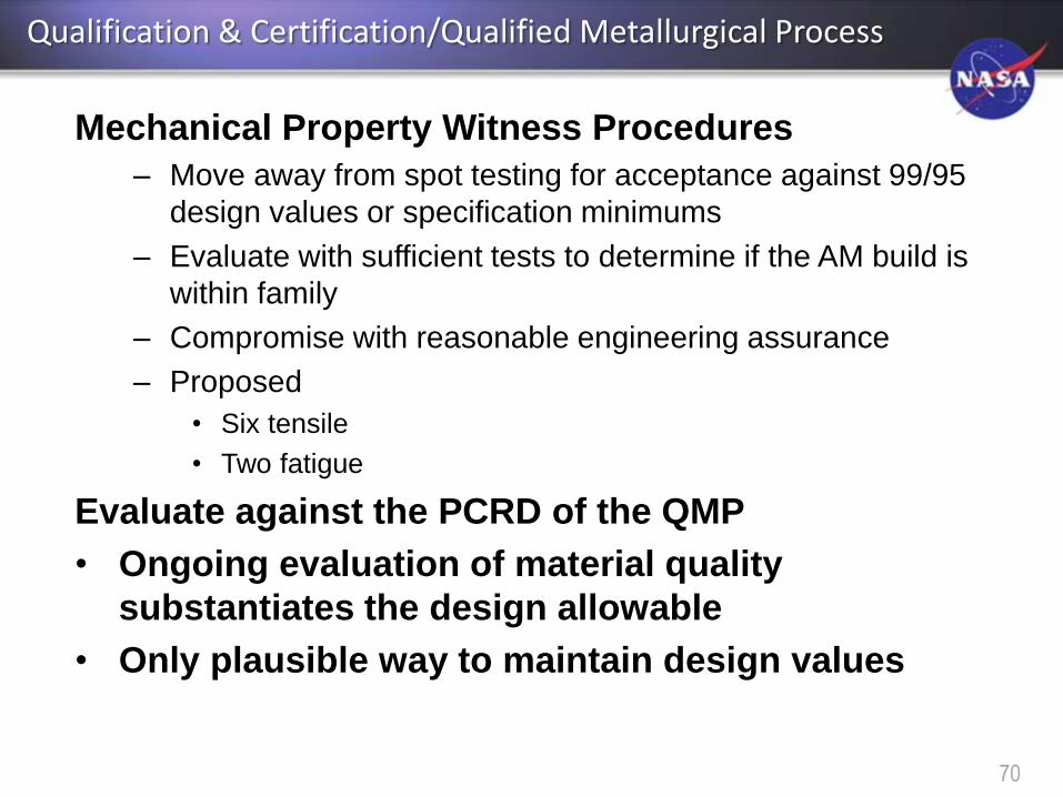
Mechanical Property Witness Procedures
– Move away from spot testing for acceptance against 99/95
design values or specification minimums
– Evaluate with sufficient tests to determine if the AM build is
within family
– Compromise with reasonable engineering assurance
– Proposed
• Six tensile
• Two fatigue
Evaluate against the PCRD of the QMP
• Ongoing evaluation of material quality
substantiates the design allowable
• Only plausible way to maintain design values
Qualification & Certification/Qualified Metallurgical Process
70

PCRD 99/95
DVS 99/95 (design)
Process
Margin
≥ 0
PCRD
Property
Property
m 1s
DVS
mwitness
switness
Qualification & Certification/Qualified Metallurgical Process
71
72
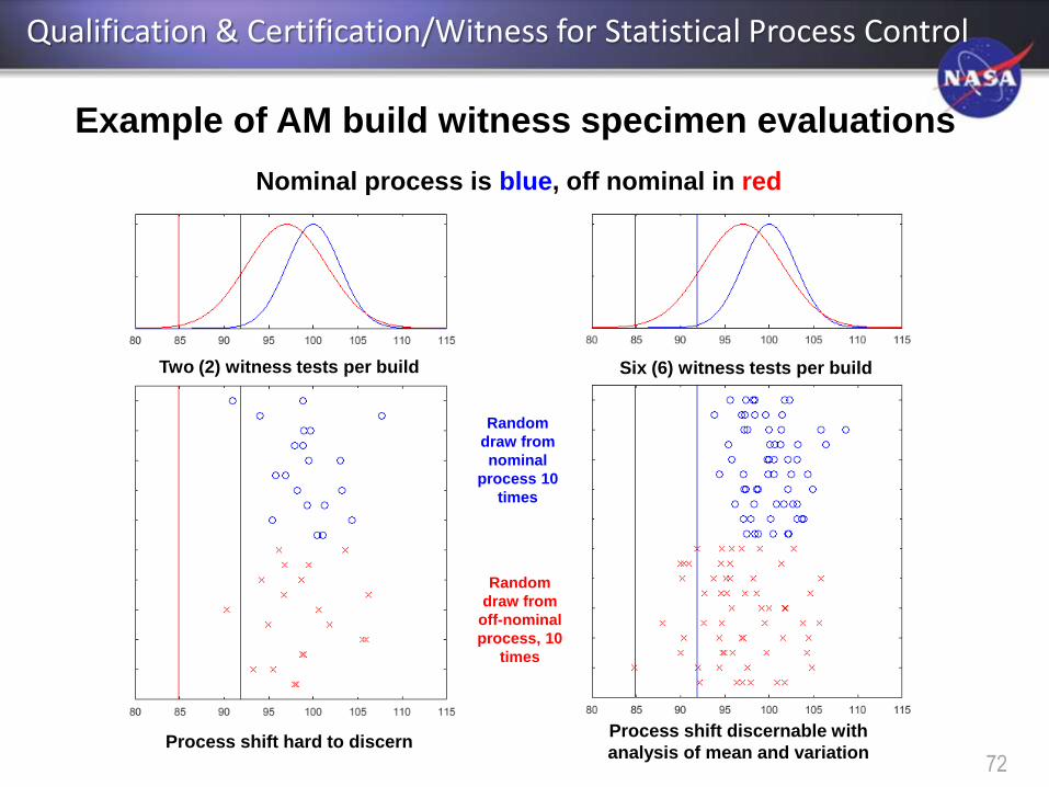
Example of AM build witness specimen evaluations
Nominal process is blue, off nominal in red
Random
draw from
nominal
process 10
times
Random
draw from
off-nominal
process, 10
times
Two (2) witness tests per build Six (6) witness tests per build
Process shift hard to discernProcess shift discernable with
analysis of mean and variation
Qualification & Certification/Witness for Statistical Process Control
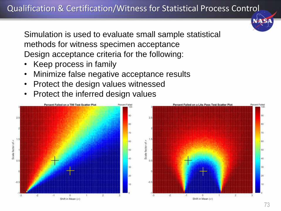
Simulation is used to evaluate small sample statistical
methods for witness specimen acceptance
Design acceptance criteria for the following:
• Keep process in family
• Minimize false negative acceptance results
• Protect the design values witnessed
• Protect the inferred design values
Qualification & Certification/Witness for Statistical Process Control
73

AM Design Value Suite
Design and
Analysis
QMP
PCWS
PCWS
Characterization builds
Part builds
Test Specimens
First Article/WS
PCRD
PC
WS
co
nsis
tent w
ith
PC
RD
Qualification & Certification/Witness for Statistical Process Control
74

• AM Does not need to be unique in certification approach
– Technology advances may bring unique opportunities
• For NASA, standardization in AM qualification is needed
– Eventually, just part of Materials & Processes, Structures,
Fracture Control standards
• Provides a consistent set of products
– Consistent evaluation of AM implementation and controls
– Consistent evaluation of risk in AM parts
• Details Discussed:
– Part Classification of considerable value to certifying body
• Rapid insight, communicate risk
– Qualified Metallurgical Process is foundational
– Witness testing for process control needs to be intelligent
Qualification & Certification/Summary of Points
75

There is more to AM than manufacturing
AM machines create a unique material product form – typically
purview of the foundry or mill
2. Cutting1. Ingot
Making
3. Heating 4. Forging 5. Heat
Treating6. Machining 7. Inspection
Subtractive Forging Process
8. Delivery
with CoC
As the ‘mill’, the AM process must assure manufacturing compliance throughout the
build process and material integrity throughout the volume of the final part.
1. Powder
Making2. Printing 4. Heat
Treating5. Machining 6. Inspection
Additive SLM Process
7. Final Part3. HIPing
Qualification & Certification/AM Qualification Challenges
76

• AM responsibility serving as the
material mill gives rise to additional
reliability concerns
– Low entry cost compared to typical
material producers
– New players in AM, unfamiliar with
the scope of AM, lacking experience
– Fabrication shops not previously
responsible for metallurgical
processes
– Research labs converting to
production
• AM machines operate with limited process feedback!
– Reliability depends upon the quality and care taken in every step
of AM operations => rigorous and meticulous controls
Concept Laser X-line
Material Mill in a Box
Qualification & Certification/AM Qualification Challenges
77

Why Standards?
• NASA: improve mission reliability
and safety
• Industry: boost business and develop
technology for American commerce
78
• Agencies must consult with voluntary
consensus standards bodies, and must participate
with such bodies in the development of voluntary
consensus standards when consultation and
participation is in the public interest
• If development of a standard is impractical
or infeasible, the agency must develop an
explanation of the reasons for impracticality and
the steps necessary to overcome the
impracticality
• Any standards developed must be necessarily
non-duplicative and noncompetitive
OMB A-119

Similar NDE of AM U.S./E.U. Efforts
79
Status on ISO TC 261 JG 59 standard for NDT of AM products
ISO TC 261 JG59 Best NDE Practice
• First VCO catalogues of AM defects showing Defect NDE linkage• No agreement between ISO TC261 JG59 and E07 to develop joint standards• ASTM WK47031 references U.S. standards; ISO standard references ISO
standards
ASTM E07.10 WK47031 NDT of AM Guide

AMSC Nondestructive Evaluation Working Group Roadmap – 9/2/16 draft
80
AMSC Qualification and Certification Working Group Roadmap – 9/14/16 draft
81

82
ASTM F42 Work Item WK56649: Standard Guide for Intentionally Seeding
Flaws in Additively Manufactured (AM) Parts (Technical Contact: Steve James)
Guide for NDE of As-built and Post-Processed Metal AM Parts (WK56649)