additional exercises for chapter 9 l’hospital’s pulley 54...
TRANSCRIPT

Additional Exercises for Chapter 9
L’Hospital’s Pulley
54. Consider the situation c = 4 and a = 3 of Example 9.1. How far below the ceiling is the center
of the pulley?
55. Refer to Figure 9.3. Show that it is possible for ∆BCF to be an isosceles triangle only when
the length a of the string to which the pulley is attached is equal to c√3.
56. Is it possible for ∠BFC in Figure 9.3 to be a right angle? [Hint: Assume this to be so.
Solve for x = EC directly by using the Pythagorean Theorem. Compare what you get with
x = a4c
(a +√
a2 + 8c2).]
Stanley is intrigued by De LHospital’s Pulley problem. Is the analysis of the geometry of the
rope-pulley configuration correct? Why not experiment? To this end, Stanley engages his wife
Bertha to join him in an effort to test ropes and pulleys. Initially there are some difficulties ...
“Where’d he learn to do that?” wonders Bertha.
but soon they begin to make progress. Convinced that he has a handle on things, Stanley sets up

De L’Hospital’s contraption in the tree in his back yard. He grabs the end of the rope, pulls himself
up, and suspends himself. Alas, Stanley has made a conceptual error ...
The neighborhood kids add insult to injury and further bruise his ego.
As if things weren’t bad enough, Stanley gets TP’ed.
Adapated from Jerry Amerongen’s cartoon Ballard Street, Dec. 2005, Jan. 2006.
About a Bowling Ball
57. In Marilyn Vos Savant’s column in Parade Magazine of August 3, 2003, a reader asks the
2

following question: “Say that I row my bowlingball to the middle of a lake. I drop the ball
over the side and watch as it sinks to the bottom. What happens to the waterlevel of the
lake? Does it rise, fall, or remain the same?” Marilyn begins her answer as follows: “Bowling
balls are heavier than water, so the level of the lake will fall.” Is she right or wrong? Provide
a “water tight” argument for the right answer. [Hint: The two cases to consider are (i) the
bowling ball submersed, and (ii) the bowling ball floating in a weightless “boat”. Which
situation displaces more water?]
The Clothesline
The theory of the suspension bridge developed in Section 9.2 relies on the assumption that the
vertical load on the bridge is uniformly distributed over the length of the bridge. This assumption
is crucial to the development. In the theory, w is taken to be the maximum weight (dead load
plus maximum live load) per foot that the bridge needs to support distributed over the number of
cables. This is the w relevant for determining the greatest loads, tensions, and compressions that
the structure is subject to. However, the entire analysis of the bridge applies to any w. So w could
be the weight per foot (distributed over the number of cables) in the situation of zero live load,
maximum live load, or anything in between. Indeed, the theory applies to any situation of a cable
under uniform horizontal load, as long as the cable is completely flexible (there is no resistance
to bending it) and inelastic (it does not get longer when stretched). The clothesline problem in
Exercise 59 below provides an example.
A clothesline 20.5 feet long is attached to two poles at points A and B. The poles are 20 feet
apart. The straight line that connects the points A and B is horizontal. (See the figure on the next
page.) The clothesline is completely flexible and inelastic.
20.5 feet
BA
C
20 feet
58. A laundry bag that has 120 wet socks (60 pairs) in it that weigh a total of 26 pounds has
been attached at the midpoint C of the clothesline. In comparison to the weight of the socks,
the weight of both the clothesline and the laundry bag are negligible.
i. Draw a careful diagram of the situation just described. How far below the line segment
AB will the point C be in this case? Answ: 2.25 feet
ii. Determine the tension T in the clothesline. Answ: 59.22 pounds
3

59. The 120 socks are taken out of the bag and suspended individually on the clothesline about
2 inches apart. Because the distance between the poles is 20 feet, the socks are distributed
at 6 socks per horizontal foot. Since 120 socks weigh 26 pounds, 6 socks weigh 1.3 pounds.
Therefore the clothesline supports w = 1.3 pounds per foot. (As before, consider the weight
of the clothesline to be negligible.) The sag in the clothesline is the distance s between C
and the segment AB. Let d = 10 be one-half the distance between the two posts. Place
a coordinate system into the figure in such a way that the origin is at C and the x-axis is
parallel to the segment AB.
i. Let L be the length of the part of the clothesline from C to B. Explain why
L =
∫ d
0
√1 +
(2s
d2
)2
x2 dx .
ii. Recall the approximation
L =
∫ d
0
√1 +
(2s
d2
)2
x2 dx ≈ d +2
3
(s
d
)2
d− 2
5
(s
d
)4
d
from the solution of Exercise 26 and use it to derive the estimate s = 1.96 feet for the
sag s in the clothesline. Answ: By the quadratic formula, s2 = 1250( 115
+√
115− 1
2500).
iii. Use the conclusion of (ii) to determine the maximum tension Tmax and the minimum
tension Tmin in the clothesline. Compare these tensions with the tension derived in
Exercise 58ii. Answ: Tmin = 33.16 pounds and Tmax = 35.62 pounds
60. You have joined the peace corpse and are working with an indigenous population in the
Amazon basin. In order to improve their abilility to move through the terrain of the rain
forrest the group wishes to build a primitive suspension bridge across a deep 90 foot wide
gorge. The plan for the bridge is simple. Solid wooden boards are to be cut, each about 5
feet long, 112
foot wide, 2 inches thick, and weighing about 10 pounds. Two heavy ropes tied
to powerful trees on each side are to span the gorge in a precisely parallel way. The boards
are to be attached by two hemp cords at each of their ends to the two arching ropes in such
a way that they form a continuous path across. Additional cords are to be used to attach the
boards to each other. The structure is to support the crossing in equally spaced single file of
about 30 natives at a time. A native weighs typically about 130 pounds. The natives begin
the construction by shooting individual cords across the gorge with bows and arrows. They
will weave the individual cords into the two heavy ropes. Since you are the sophisticated
American, they had asked you about the ultimate strength that each of their ropes needs to
have. What did you tell them?
4
The Bridge and its Cable
A look back at the argument in Chapter 9.2 of the text that establishes the equations T0 = Tx cos θ
and wx = Tx sin θ by balancing the forces involved, will show that it does not conform to the
standard requirement that all forces involved act at the same point. The next two exercises outline
an approach that does.
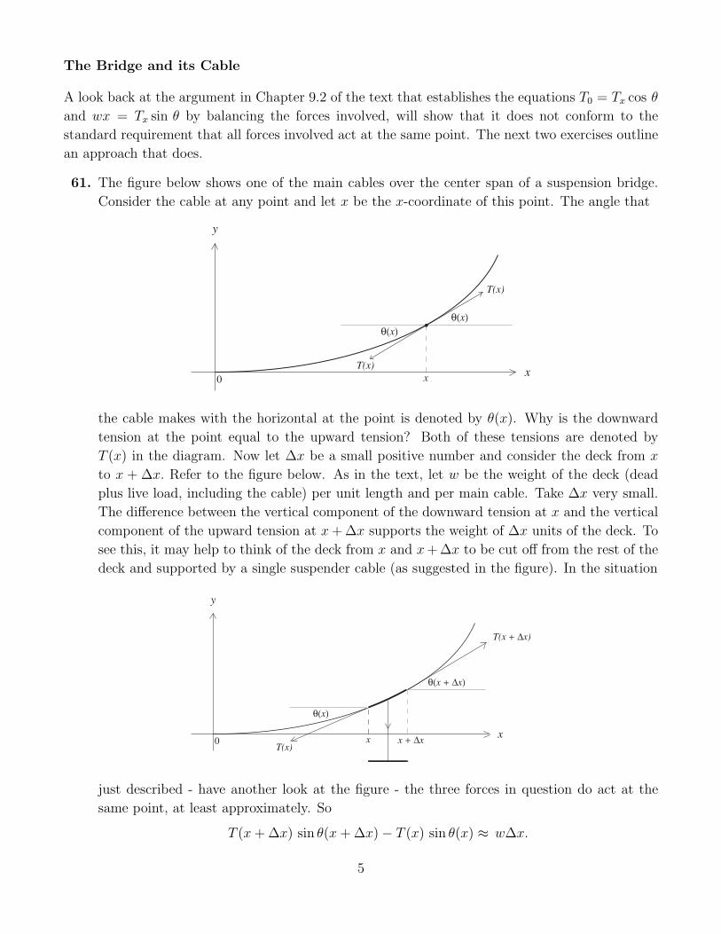
61. The figure below shows one of the main cables over the center span of a suspension bridge.
Consider the cable at any point and let x be the x-coordinate of this point. The angle that
q(x)
y
T(x)
xx0
q(x)
T(x)
the cable makes with the horizontal at the point is denoted by θ(x). Why is the downward
tension at the point equal to the upward tension? Both of these tensions are denoted by
T (x) in the diagram. Now let ∆x be a small positive number and consider the deck from x
to x + ∆x. Refer to the figure below. As in the text, let w be the weight of the deck (dead
plus live load, including the cable) per unit length and per main cable. Take ∆x very small.
The difference between the vertical component of the downward tension at x and the vertical
component of the upward tension at x + ∆x supports the weight of ∆x units of the deck. To
see this, it may help to think of the deck from x and x + ∆x to be cut off from the rest of the
deck and supported by a single suspender cable (as suggested in the figure). In the situation
q(x + Dx)
y
T(x + Dx)
xx0 x + Dx
q(x)
T(x)
just described - have another look at the figure - the three forces in question do act at the
same point, at least approximately. So
T (x + ∆x) sin θ(x + ∆x)− T (x) sin θ(x) ≈ w∆x.
5

The smaller the ∆x, the better the approximation. Use this fact to compute ddx
(T (x) sin θ(x))
and deduce that T (x) sin θ(x) = wx.
62. This exercise is the horizontal version of the previous exercise. Because the horizontal com-
ponent of the tension at x must balance that at x + ∆x, note that
T (x + ∆x) cos θ(x + ∆x)− T (x) cos θ(x) ≈ 0.
The smaller the ∆x, the better the approximation. Can you conclude that ddx
(T (x) cos θ(x)) =
0? Why not? Consider the force T (x + ∆x) cos θ(x + ∆x) − T (x) cos θ(x). This force will
produce a horizontal acceleration, say a, on the piece of the deck from x to x+∆x. If m is the
mass of the deck per unit length (dead plus live load, including the cable, and again per main
cable), then T (x + ∆x) cos θ(x + ∆x)− T (x) cos θ(x) = (m∆x)× a. Use this consideration
T(x) cos q(x)T(x+Dx) cos q(x+Dx)
q(x + Dx)
y
xx0 x + Dx
q(x)
to show that ddx
(T (x) cos θ(x)) = 0 and conclude that T (x) cos θ(x) is a constant equal to the
tension T0 at x = 0.
63. Consider the patterns of circles at the top of page 290. Each represents the cross-section of
a cable with the circles representing a hexagonal configuration of strands. The horizontal
diagonals contain 1, 3, and 5 circles respectively. Construct a cable with a hexagonal arrange-
ment of strands as follows. Start with any odd number 2k + 1 of circles along the horizontal
diagonal. Following the pattern, put 2k circles in the row above the diagonal, put 2k − 1
circles in the row above that, and continue in this way. Why will the i-th row above the diag-
onal have 2k − (i− 1) circles in it? How many rows i above the diagonal are needed so that
the cluster of circles on and above the diagonal form the upper part of an hexagonal array?
After resolving this matter, do a similar thing below the diagonal. Count the total number
of circles above and below the diagonal by matching up the first row above the diagonal with
the last row below the diagonal, the second row above the diagonal with the next to last row
below the diagonal, and so on. Show that the total number of circles in the hexagonal array
is 3k2 + 3k + 1. Does this provide the correct number of circles for the patterns at the top of
page 290? Does this result agree with the the conclusion (as to the number of strands in a
cable) of Exercise 22?
6

About the Golden Gate
A suspension bridge is really a “living thing”. It is designed to move in response to changes
in loads, temperatures, and wind conditions. For example, under a sustained transverse wind, the
deck of the Golden Gate Bridge can move laterally by as much as 27.7 feet. During the winter
storms in 1982, the main span bowed approximately 6 to 7 feet. The deck over the center span
experiences a maximum downward deflection of 10.8 ft below horizontal position (this occurs in the
situation of Exercise 64 below) and a maximum upward deflection of 5.8 feet (in the situation of
Exercise 65 below). For a wealth of data about the Golden Gate, see
http://www.goldengatebridge.org/research/factsGGBDesign.html
The Golden Gate has also undergone major structural modifications since the time it was built. In
1953 a new bottom lateral bracing system was added and in 1985 the original concrete bridge deck
was replaced with a steel deck. The current dead load is 20,170 pounds per foot (down from the
21,300 pounds per foot specified in the original design). Some of the original structural data are
still correct. For example, the live load capacity is 4000 pounds per foot (for both the center and
the side spans), the center span is 4200 feet, the towers have a height of 746 feet, and the bridge
still has 2 main cables. The sag - in the situation of zero live load throughout the bridge - is 470
feet. [All the information above was supplied by Jerry Kao, supervising civil engineer at the Golden
Gate Bridge District, in May of 2003.]
64. Use the current data for Golden Gate Bridge to show that the maximal tension in the main
cable in the situation of zero live load is approximately 51,837,000 pounds. Derive the ap-
proximation ∫ d
0
√1 +
(2s
d2
)2
x2 dx ≈ d +2
3
(s
d
)2
d− 2
5
(s
d
)4
d +4
7
(s
d
)6
d
using the strategy of Exercises 24 to 26. Show that the length in one of the main cables over
the center span is approximately 4336 feet.
65. Under the condition of maximal live load over the center span and zero live load over the side
spans and at a temperature of 110◦ Fahrenheit, the sag in the cable increases by 10.8 feet
and each of the towers bends toward the center of the bridge so that the top of the tower is
about 1.5 feet from its vertical position. Determine the maximal tension as well as the length
of one of the main cables over the center span. What d, w, and s should you use? Are your
conclusions consistent with those of Exercise 64?
66. Under the condition of zero live load over the center span and maximal live load over the side
spans and at a temperature of 30◦ Fahrenheit, the sag in the cable decreases by 5.8 feet and
each of the towers bends away from the center of the bridge so that the top of the tower is
about 1.8 feet from its vertical position. Determine the maximal tension as well as the length
7

of one of the main cables over the center span. What d, w, and s should you use this time?
Compare the answers with those of Exercises 64 and 65.
Swinging Things
In the determination of the index of inertia of a rotating object any force can be considered. Once
the corresponding torque and angular acceleration are determined, the index of inertia is obtained
by dividing the torque by the angular acceleration. In applications, say to the seesaw and the rolling
ball, specific forces, gravity, or a component of gravity, and friction are inserted into the discussion.
The single weightless spoke of length r and the small piece of mass m attached to it serves as an
example. In Section 9.3B the consideration of an abstract force and the torque it produced provided
the index of inertia mr2 of this system. But what if this spoke and and mass system is acted on by
gravity alone? Then this system becomes the basic pendulum.
67. The seesaw shown below consists of a homogeneous rigid board and supports the weights w1
and w2. It is in horizontal position, and it is in balance. Suppose that it weighs u units per
l l
x1
w2
x 2
w1
unit length. Then the torques to the left of the fulcrum balance those on the right. So by the
point made in the Note that follows the Solution of Exercise 31,
(ul1)l12
+ w1x1 = (ul2)l22
+ w2x2 .
Suppose that the board is tilted so that it makes an angle β with the horizontal and that the
weights retain their position. By decomposing gravity into components that are respectively
parallel and perpendicular to the board and by arguing as in Exercise 31 show that the torque
of the forces generated on the left of the fulcrum is (cos β)((ul1)l12
+ w1x1). Because a similar
fact holds for the right side as well, it follows that your childhood experience is confirmed:
the seesaw remains in balance.
68. Consider an abstract version of a pendulum. A mass m is supported by a thin weightless rod
of length r that is attached to a fixed point C about which it can rotate freely. Suppose that
the rod makes an angle of θ0 > 0 (in radians) with the vertical at time t = 0 and is released.
Let the angle (again in radians) measured from the vertical to the rod be θ(t) at any time
t ≥ 0. So θ(0) = θ0. Notice that −θ0 ≤ θ(t) ≤ θ0 for any t. If θ(t) can be determined explicitly
(as a function of t), then the motion of the pendulum is understood. Recall from Section 9.3B
that that the index of inertia of this system is mr2 and show that
θ′′(t) = −g
rsin θ(t).
8

q(t)
m
r
mg
C
The minus sign is needed, because when θ(t) is positive, then the angular velocity increases in
the clockwise direction, so that sin θ(t) and θ′′(t) have opposite signs. A similar thing is true
if θ(t) is negative. It turns out that this equation does determine the function θ(t), but only
in terms of a power series in the variable t and not in terms of standard functions. Suppose,
however, that θ0 is small. Then θ(t) is small for any t, and therefore, sin θ(t) ≈ θ(t) for any
t ≥ 0. Underlying this approximation is the fact that y = x is the tangent line to the graph
of y = sin x at the point (0, 0). For example, for θ0 = 10 degrees, θ0 = π18
= 0.1745329 radians
and sin θ0 = 0.1736481, for θ0 = 5 degrees, θ0 = 0.0872664 and sin θ0 = 0.0871557, and for
θ0 = 1 degree, θ0 = 0.0174532 radians and sin θ0 = 0.0174524. So in case θ0 is small, the
solution of
θ′′(t) = −g
rθ(t)
with the initial contition θ(0) = θ0 provides an approximation for θ(t). Can you think of
a function that satisfies this condition? [Hint: Think trigonometric and then modify your
thinking.]
Galileo and his Planes
The problem below considers a ball rolling down from the top of an inclined plane having started
from rest. As in Section 9.3 assume that it rolls without slippage and retardation (other than the
frictional force that rotates the ball). For the solutions make use of facts and equations developed
in Section 9.3C.
69. i. Show that the velocity of the ball is proportional to the square root of the distance it
has rolled. What is the constant of proportionality?
ii. Show that the average velocity of the ball during its roll to any point on the plane is 12
the velocity that it has the instant it reaches that point.
iii. Show that the velocity of the ball at any point depends only on the (vertical) drop h to
that point.
iv. Show that two balls rolling from rest from the top to the bottom of two inclined planes
of the same height have the same velocity when they arrive at the bottom of their planes.
70. Consider two balls starting simultaneously from rest. They start from the top of the two
ramps shown below, one curved, and the other straight. Draw a figure between the two that
9

hh
are given that illustrates that the two balls have the same velocity whenever they are the
same vertical distance from the ground. [Hint: Use one of the facts of Exercise 65.]
71. Consider a vertical inclined plane and a ball rolling down it without slippage. Can this
situation be realized experimentally? [Hint: start with a standard yoyo.] Suppose such a
plane has its highest point at the origin of a y-axis. Let a ball roll down the plane starting at
y = 0 at time t = 0. Why is the acceleration of this ball −5g7
and the y-coordinate of its center
−5g14
t2 at any time t ≥ 0? How far in feet does this ball roll in 3 seconds. If this ball were to
be dropped instead (no rolling) how much farther would it fall in the same three seconds?
72. A homogeneous ball rolls down an inclined plane that nmakes an angle of 30◦ with the hor-
izontal. Its radius is .05 meters and units and mass is 0.25 kilograms. What is the gravita-
tional force on the ball in newtons. What is the angular acceleration of the rolling ball in
meters/sec2.? What is the frictional force force on the ball (in newtons)?
73. A circle of radius r in the x-y plane as shown and let y = mx be the equation of a non-vertical
line through the origin. Show that the distance between the origin O and the other point of
O
E
C = (0, r)
y = mx
intersection E is 2mr√1+m2 .
74. Consider an inclined plane of any inclination along the cord of a circle of radius r. Its highest
point O is at the top of the circle. Suppose that a ball is released from rest from the highest
point of the plane at time t = 0. Show that it arrives at the point E at time t = 2√
75g
r. Why
is this time the same for any inclination β? [Hint: What is the distance that the ball rolls
during any time t? What is the length of the cord in terms of r and β? Use Exercise 64 to
answer the last question.]
10

bE
O
75. Consider any number of inclined planes all with the same highest point O. Release a ball
from rest on all of them simultaneously at time t = 0. Let any amount of time t elapse. The
O
figure on the next page depicts a typical situation. Galileo concluded correctly that O and all
the points of contact of the balls with their planes lie on a circle. Verify this using Exercise
62. What is the radius of this circle in terms of the elapsed time t?
76. Galileo describes the following method for sketching parabolas. ”I use an exquisitly round
bronze ball, no larger than a nut; this is rolled on a metal mirror held not vertically but
somewhat tilted, so that the ball in motion runs over it and presses it lightly. ... To descibe
parabolas in this way, the ball must be somewhat warmed and moistened ... so that the traces
it will leave shall be more apparent on the mirror.” This translation of Galileo’s Italian can
be found on page 142, of the translation of Galileo’s Discorsi e dimostrazioni matematiche,
intorno a due nuove scienze attenenti alla mechanica & i movimento locali, Leyden, 1638, by
the historian Stillman Drake. The figure on the next page depicts such a situation. Show that
O
11

Galileo’s procedure does generate parabolas. [Hint: Place a co-ordinate system as shown and
make use of a combination of the discussions in Sections 6.5 and 9.3C.]
More About Light
77. Here is how Olaf Roemer estimated the speed of light. The diagram below shows the Earth in
orbit around the Sun and the innermost moon (known as Io today) in orbit around Jupiter.
Denote the period of Io by T . With the Earth in position A Roemer measured the time m
between two consecutive ”rises” of Io from Jupiter’s shadow to be about 4212
hours. How is
Sun
B
A
D C
B'
JupiterIo
Earth
the difference between m and T related to Roemer’s quest? About 53 days later with the
Earth in position B, Roemer again measured the time between consecutive rises of Io. He
found that this measurement exceeded the first by 10 minutes. In the diagram above, B′ is
chosen so that the distance from Io to B and B′ is the same. After this second measurement,
what did Roemer know about the time light travels from A to B′? After carrying out such
measurements for ten years (!), Roemer concluded that light covers the distance from D to C
- the diameter of the Earth’s orbit - in about 22 minutes. Given that at the time of Roemer’s
measurements in the 1670s the diameter of the Earth’s orbit was thought to be about 174
million miles (the modern value is 186 million miles) what estimate for the speed of light did
Roemer get? If your answer is 30% less than the modern value of 186,000 miles per second,
then you got it right.
With the phenomenon of refraction in mind, the question arises as to how close Aristarchus’s
geometric methods of Chapter 1 could have come in determining the accurate values of the radius
rS of the Sun and the distance DS from the Earth to the Sun. Aristarchus’s three measurements are
described in points C, D, and E of Section 1.5. Of the three, the measurement of the angle ∠MES
is by far the most delicate to undertake. See Figure 1.23 of Section 1.5. This measurement also has
the greatest impact on the estimates of the distances. The fact that the value of 87◦ observed by
Aristarchus is off by over 2◦ is the primary reason for the inaccuracy of his estimates. The study of
the impact of refraction undertaken by the next exercise will therefore focus on this angle. What is
the impact of refraction on this measurement?
12

78. Let’s first look at the geometry of the triangle angle of Figure 1.23. Let DM the distance
from the Earth to the Moon and let ∠MES = θ. Note that cos θ = DM
DS. Taking the modern
average values for DM and DS, as provided in Table 1.4 of Section 1.5 and Section 4.7, we get
cos θ = 2.389×10⁵
9.296×107 = 2.570 × 10⁻³. So by the inverse cosine button of a calculator, θ = 89.85◦.
This is the geometric - rather than the sighted - value of the angle θ. We now turn to the
measurement of this angle from the surface of the Earth. Assume that a precisely calibrated
telescope is available. For the sake of illustration, assume that when the angle θ is measured,
the center of the Sun is sighted to be exactly 10◦ above the horizon and that the Moon is
much higher in the sky than the Sun.
i. Review the narrative of Exercise 9J and the information provided by Figure 9.66 and
Table 9.2. Taking S to be the center of the Sun in the figure, observe that zapp = 80◦.
Use the table to verify that the corresponding ztrue is equal to 80◦+ 3193600
◦= 80◦+0.089◦.
So the true position of the Sun is close to 9.91◦ above that horizon.
ii. The impact of refraction on the observed line of sight to the Moon is much less. Why?
So ignore this effect and show that the sighted value for θ is about 89.76◦.
iii. Use this sighted value for the angle θ in combination with the values of DM = 2.389×10⁵
miles for the distance from the Earth to the Moon and the value rM = 1080 miles for the
radius of the Moon, to estimate the distances DS and rS with Aristarchus’s approach.
Are you satisfied with the accuracy?
13