addendum no. 1 - d1jxr8mzr163g2.cloudfront.net · addendum no. 1 water treatment plant expansion...
TRANSCRIPT
WATER TREATMENT PLANT EXPANSION
FOR
BOWLING GREEN MUNICIPAL UTILITIES
ADDENDUM NO. 1
ISSUE DATE: October 15, 2018
BID DATE: November 8, 2018
SMITH SECKMAN REID, INC.
2995 Sidco Drive
Nashville, TN 37204
615-383-1113
SSR No. 16-41-027.0
1641027.0 10/15/2018

ADDENDUM NO. 1 WATER TREATMENT PLANT EXPANSION BOWLING GREEN MUNICIPAL UTILITIES, BOWLING GREEN, KENTUCKY Page 2 of 7
– 2
ADDENDUM NO. 1
October 15, 2018
BID DATE: November 8, 2018
TO ALL CONTRACTORS AND SUPPLIERS:
The attention of all prospective bidders for the subject project is directed to the following
additions, deletions and modifications to the Contract Documents.
This Addendum consists of 7 pages, with attachments.
An attachment consisting of the following:
1. Replacement Table A-13: Pipe and Label Color Schedule for Section 09 96 00.
2. Section 21 05 00 – Common Work Requirements for Fire Protection
Addendum
Item
Page or
Drawing
Location and Description of Change
S-1. 00 11 13 – 1 Delete the seventh paragraph in its entirety and replace with the following
(date of pre-bid meeting is being changed; time remains unchanged):
“In accordance with the “Instructions to Bidders,” a Mandatory Pre-
Bid Conference will be held on Tuesday, October 23, 2018 at 10:00 am
local time at the Bowling Green Municipal Administration Building
located at 801 Center Street, Bowling Green, Kentucky 42101 (a site
visit will immediately follow). Attendance at said conference is a pre-
requisite for submitting a bid. Bids received from prospective bidders
who did not attend this pre-bid conference shall not be opened.”
S-2. 00 41 00 – 10 Delete the description of Line Item No. 13 in Schedule E and replace with
the following:
“40 90 00: Magnetic Flowmeters”.
S-3. 40 90 00 – 21 In Article 2.12.A, after the word “50W”, add the following:
“(other acceptable manufacturers are Krohne and Rosemont)”.
S-4. 01 11 13 – 2 In Article 1.02.B.2, delete phrase “As part of base and alternative bids” and
replace with the following:
“As part of base bid”.
1641027.0 10/15/2018
ADDENDUM NO. 1 WATER TREATMENT PLANT EXPANSION BOWLING GREEN MUNICIPAL UTILITIES, BOWLING GREEN, KENTUCKY Page 3 of 7
– 3
Addendum
Item
Page or
Drawing
Location and Description of Change
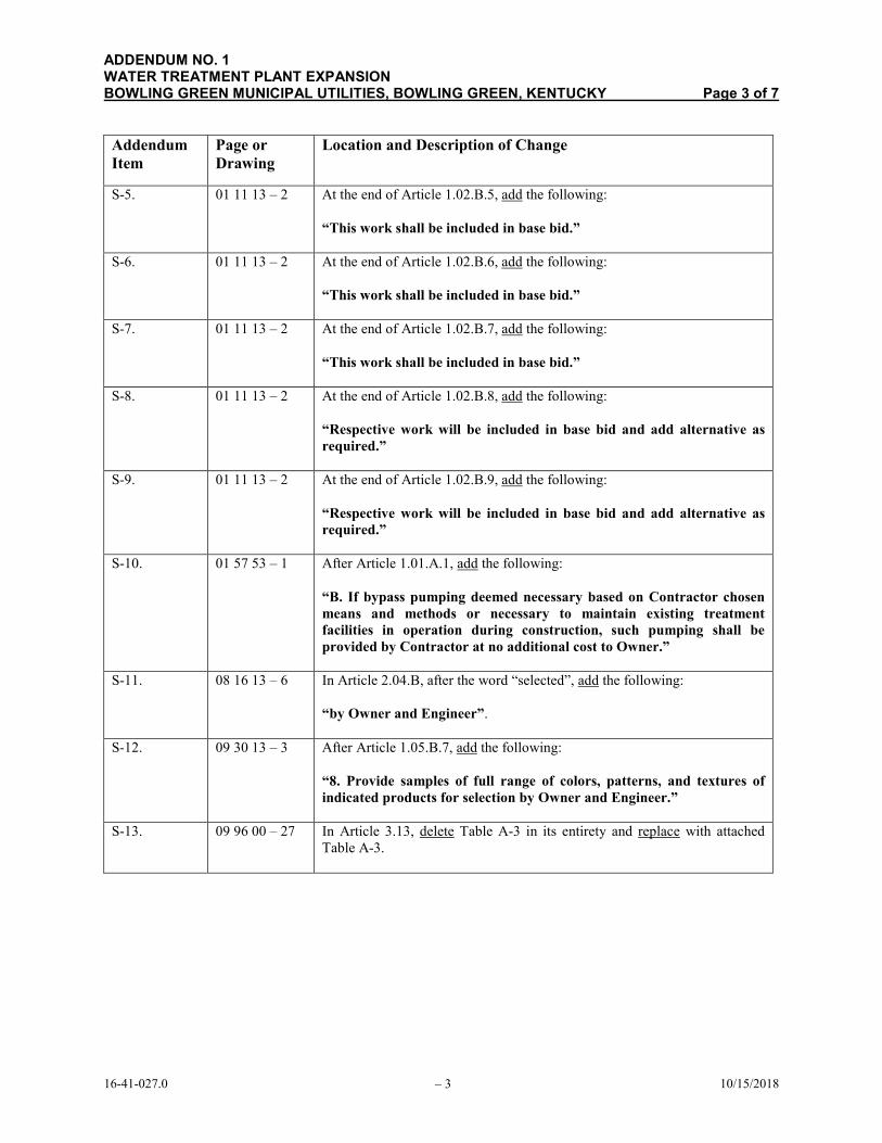
S-5. 01 11 13 – 2 At the end of Article 1.02.B.5, add the following:
“This work shall be included in base bid.”
S-6. 01 11 13 – 2 At the end of Article 1.02.B.6, add the following:
“This work shall be included in base bid.”
S-7. 01 11 13 – 2 At the end of Article 1.02.B.7, add the following:
“This work shall be included in base bid.”
S-8. 01 11 13 – 2 At the end of Article 1.02.B.8, add the following:
“Respective work will be included in base bid and add alternative as
required.”
S-9. 01 11 13 – 2 At the end of Article 1.02.B.9, add the following:
“Respective work will be included in base bid and add alternative as
required.”
S-10. 01 57 53 – 1 After Article 1.01.A.1, add the following:
“B. If bypass pumping deemed necessary based on Contractor chosen
means and methods or necessary to maintain existing treatment
facilities in operation during construction, such pumping shall be
provided by Contractor at no additional cost to Owner.”
S-11. 08 16 13 – 6 In Article 2.04.B, after the word “selected”, add the following:
“by Owner and Engineer”.
S-12. 09 30 13 – 3 After Article 1.05.B.7, add the following:
“8. Provide samples of full range of colors, patterns, and textures of
indicated products for selection by Owner and Engineer.”
S-13. 09 96 00 – 27 In Article 3.13, delete Table A-3 in its entirety and replace with attached
Table A-3.
1641027.0 10/15/2018
ADDENDUM NO. 1 WATER TREATMENT PLANT EXPANSION BOWLING GREEN MUNICIPAL UTILITIES, BOWLING GREEN, KENTUCKY Page 4 of 7
– 4
Addendum
Item
Page or
Drawing
Location and Description of Change
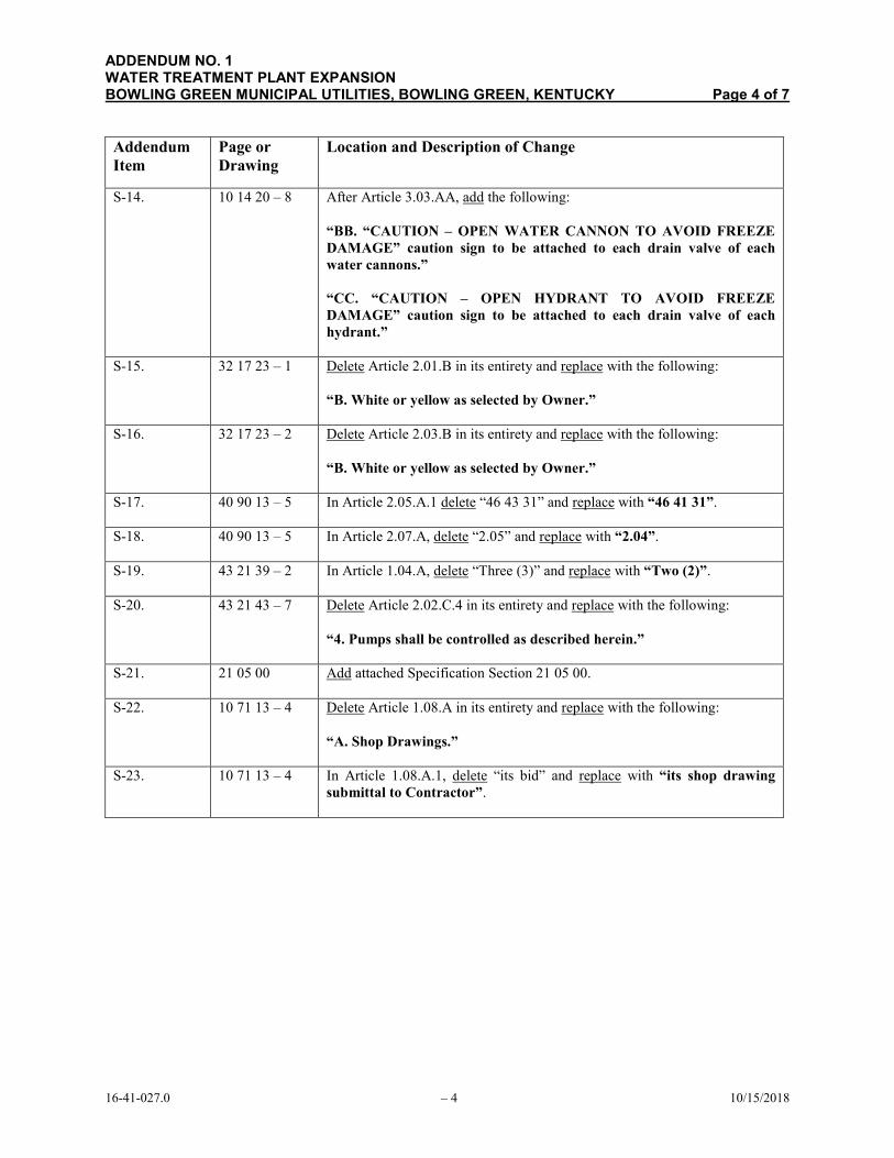
S-14. 10 14 20 – 8 After Article 3.03.AA, add the following:
“BB. “CAUTION – OPEN WATER CANNON TO AVOID FREEZE
DAMAGE” caution sign to be attached to each drain valve of each
water cannons.”
“CC. “CAUTION – OPEN HYDRANT TO AVOID FREEZE
DAMAGE” caution sign to be attached to each drain valve of each
hydrant.”
S-15. 32 17 23 – 1 Delete Article 2.01.B in its entirety and replace with the following:
“B. White or yellow as selected by Owner.”
S-16. 32 17 23 – 2 Delete Article 2.03.B in its entirety and replace with the following:
“B. White or yellow as selected by Owner.”
S-17. 40 90 13 – 5 In Article 2.05.A.1 delete “46 43 31” and replace with “46 41 31”.
S-18. 40 90 13 – 5 In Article 2.07.A, delete “2.05” and replace with “2.04”.
S-19. 43 21 39 – 2 In Article 1.04.A, delete “Three (3)” and replace with “Two (2)”.
S-20. 43 21 43 – 7 Delete Article 2.02.C.4 in its entirety and replace with the following:
“4. Pumps shall be controlled as described herein.”
S-21. 21 05 00 Add attached Specification Section 21 05 00.
S-22. 10 71 13 – 4 Delete Article 1.08.A in its entirety and replace with the following:
“A. Shop Drawings.”
S-23. 10 71 13 – 4 In Article 1.08.A.1, delete “its bid” and replace with “its shop drawing
submittal to Contractor”.
1641027.0 10/15/2018
ADDENDUM NO. 1 WATER TREATMENT PLANT EXPANSION BOWLING GREEN MUNICIPAL UTILITIES, BOWLING GREEN, KENTUCKY Page 5 of 7
– 5
Addendum
Item
Page or
Drawing
Location and Description of Change
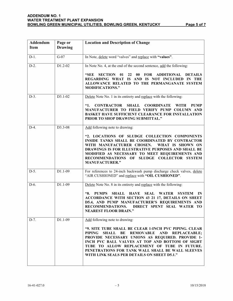
D-1. G-07 In Note, delete word “valves” and replace with “values”.
D-2. D1.2-02 In Note No. 4, at the end of the second sentence, add the following:
“SEE SECTION 01 22 00 FOR ADDITIONAL DETAILS
REGARDING WHAT IS AND IS NOT INCLUDED IN THE
ALLOWANCE RELATED TO THE PERMANGANATE SYSTEM
MODIFICATIONS.”
D-3. D3.1-02 Delete Note No. 1 in its entirety and replace with the following:
“1. CONTRACTOR SHALL COORDINATE WITH PUMP
MANUFACTURER TO FIELD VERIFY PUMP COLUMN AND
BASKET HAVE SUFFICIENT CLEARANCE FOR INSTALLATION
PRIOR TO SHOP DRAWING SUBMITTAL.”
D-4. D3.3-08 Add following note to drawing:
“2. LOCATIONS OF SLUDGE COLLECTION COMPONENTS
INSIDE TANKS SHALL BE COORDINATED BY CONTRACTOR
WITH MANUFACTURER CHOSEN. WHAT IS SHOWN ON
DRAWINGS IS FOR ILLUSTRATIVE PURPOSES AND SHALL BE
MODIFIED AS NECESSARY TO MEET REQUIREMENTS AND
RECOMMENDATIONS OF SLUDGE COLLECTOR SYSTEM
MANUFACTURER.”
D-5. D1.1-09 For references to 24-inch backwash pump discharge check valves, delete
“AIR CUSHIONED” and replace with “OIL CUSHIONED”.
D-6. D1.1-09 Delete Note No. 8 in its entirety and replace with the following:
“8. PUMPS SHALL HAVE SEAL WATER SYSTEM IN
ACCORDANCE WITH SECTION 43 21 17, DETAILS ON SHEET
D5.4, AND PUMP MANUFACTURER’S REQUIREMENTS AND
RECOMMENDATIONS. DIRECT SPENT SEAL WATER TO
NEAREST FLOOR DRAIN.”
D-7. D1.1-09 Add following note to drawing:
“9. SITE TUBE SHALL BE CLEAR 1-INCH PVC PIPING. CLEAR
PIPING SHALL BE REMOVABLE AND REPLACEABLE;
PROVIDE NECESSARY UNIONS AS REQUIRED. PROVIDE 1-
INCH PVC BALL VALVES AT TOP AND BOTTOM OF SIGHT
TUBE TO ALLOW REPLACEMENT OF TUBE IN FUTURE.
PENETRATIONS FOR TANK WALL SHALL BE WALL SLEEVES
WITH LINK SEALS PER DETAILS ON SHEET D5.1.”
1641027.0 10/15/2018

ADDENDUM NO. 1 WATER TREATMENT PLANT EXPANSION BOWLING GREEN MUNICIPAL UTILITIES, BOWLING GREEN, KENTUCKY Page 6 of 7
– 6
Addendum
Item
Page or
Drawing
Location and Description of Change
D-8. D1.1-09A Delete Note Nos. 7 and 8 in their entirety and replace with the following:
“7. ROUTE DISCHARGE OF BACKWASH PUMP AIR RELEASE
VALVE (ARV) TO NEAREST FLOOR DRAIN. SIZE OF DRAIN
PER ARV/PUMP MANUFACTURER’S REQUIREMENTS AND
RECOMMENDATIONS.
8. PUMPS SHALL HAVE SEAL WATER SYSTEM IN
ACCORDANCE WITH SECTION 43 21 17, DETAILS ON SHEET
D5.4, AND PUMP MANUFACTURER’S REQUIREMENTS AND
RECOMMENDATIONS. DIRECT SPENT SEAL WATER TO
NEAREST FLOOR DRAIN.”
D-9. D1.1-09A For references to 24-inch backwash pump discharge check valves, delete
“AIR CUSHIONED” and replace with “OIL CUSHIONED”.
D-10. D1.1-10 Delete all references to “CHEMICAL COAG TANK” and replace with
“CHEMICAL COAG DAY TANK”.
D-11. D1.1-10A Delete all references to “CHEMICAL COAG TANK” and replace with
“CHEMICAL COAG DAY TANK”.
D-12. D1.1-11 In Section A, delete reference to containment wall height of “481.50” and
replace with “482.00”.
D-13. D3.1-11 In Sections B, C, and D, delete references to containment wall height of
“481.50” and replace with “482.00”.
D-14. D5.9 In Plan View, delete word “pluged” and replace with “plugged”.
D-15. M0.1 In General Notes for Air Distribution Device Schedule, in Note No. 2,
delete word “REFLECTED”.
D-16. M0.1 In General Notes for Air Distribution Device Schedule, delete Note No. 11
in its entirety.
D-17. M0.1 In Remarks for Air Distribution Device Schedule, in Remark H, delete word
“ARCHITECT” and replace with “ENGINEER”.
D-18. M0.1 In Mechanical General Notes, add following note:
“19. PROVIDE ALUMINUM INSECT SCREENS AT ALL LOUVERS
AND OTHER EXTERIOR INLETS/OUTLETS.”
D-19. M5.2 In Detail No. 1, Roof Pipe Support, delete “NOTE TO DESIGNER” in its
entirety.
D-20. P0.1 In “Domestic Water Heater Schedule”, for WH-09-01, for Electrical Phase,
delete “3” and replace with “1”.
1641027.0 10/15/2018
ADDENDUM NO. 1 WATER TREATMENT PLANT EXPANSION BOWLING GREEN MUNICIPAL UTILITIES, BOWLING GREEN, KENTUCKY Page 7 of 7
– 7
Addendum
Item
Page or
Drawing
Location and Description of Change
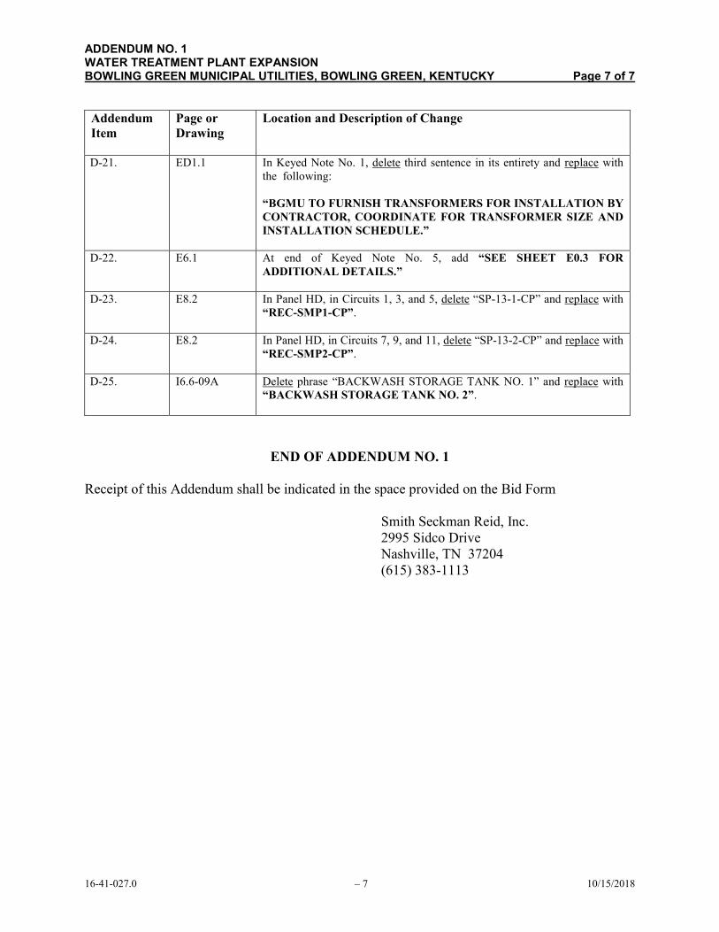
D-21. ED1.1 In Keyed Note No. 1, delete third sentence in its entirety and replace with
the following:
“BGMU TO FURNISH TRANSFORMERS FOR INSTALLATION BY
CONTRACTOR, COORDINATE FOR TRANSFORMER SIZE AND
INSTALLATION SCHEDULE.”
D-22. E6.1 At end of Keyed Note No. 5, add “SEE SHEET E0.3 FOR
ADDITIONAL DETAILS.”
D-23. E8.2 In Panel HD, in Circuits 1, 3, and 5, delete “SP-13-1-CP” and replace with
“REC-SMP1-CP”.
D-24. E8.2 In Panel HD, in Circuits 7, 9, and 11, delete “SP-13-2-CP” and replace with
“REC-SMP2-CP”.
D-25. I6.6-09A Delete phrase “BACKWASH STORAGE TANK NO. 1” and replace with
“BACKWASH STORAGE TANK NO. 2”.
END OF ADDENDUM NO. 1
Receipt of this Addendum shall be indicated in the space provided on the Bid Form
Smith Seckman Reid, Inc.
2995 Sidco Drive
Nashville, TN 37204
(615) 383-1113
1641027.0 10/15/2018
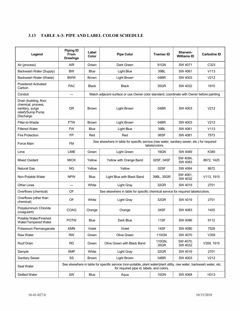
3.13 TABLE A-3: PIPE AND LABEL COLOR SCHEDULE
Legend Piping ID
From Drawings
Label Color
Pipe Color Tnemec ID Sherwin-
Williams ID Carboline ID
Air (process) AIR Green Dark Green 91GN SW 4071 C323
Backwash Water (Supply) BW Blue Light Blue 39BL SW 4061 V113
Backwash Water (Waste) BWW Brown Light Brown 04BR SW 4003 V212
Powdered Activated Carbon
PAC Black Black 35GR SW 4032 1915
Conduit --- Match adjacent surface or use Owner color standard; coordinate with Owner before painting
Drain (building, floor, chemical, process, sanitary, surge relief)/Sump Pump Discharge
DR Brown Light Brown 04BR SW 4003 V212
Filter-to-Waste FTW Brown Light Brown 04BR SW 4003 V212
Filtered Water FW Blue Light Blue 39BL SW 4061 V113
Fire Protection FP Red Red 06SF SW 4081 7573
Force Main FM See elsewhere in table for specific service (raw water, sanitary sewer, etc.) for required
labels/colors.
Lime LIME Green Light Green 19GN SW 4069 K385
Mixed Oxidant MIOX Yellow Yellow with Orange Band 02SF, 04SF SW 4084, SW 4083
8672, 1420
Natural Gas NG Yellow Yellow 02SF SW 4084 8672
Non-Potable Water NPW Blue Light Blue with Black Band 39BL, 35GR SW 4061, SW 4032
V113, 1915
Other Lines --- White Light Gray 32GR SW 4019 2701
Overflows (chemical) OF See elsewhere in table for specific chemical service for required labels/colors.
Overflows (other than chemical)
OF White Light Gray 32GR SW 4019 2701
Polyaluminum Chloride (coagulant)
COAG Orange Orange 04SF SW 4083 1420
Potable Water/Finished Water/Tempered Water
POTW Blue Dark Blue 11SF SW 4086 9112
Potassium Permanganate KMN Violet Violet 14SF SW 4080 7528
Raw Water RW Green Olive Green 110GN SW 4070 V359
Roof Drain RD Green Olive Green with Black Band 110GN, 35GR
SW 4070, SW 4032
V359, 1915
Sample SMP White Light Gray 32GR SW 4019 2701
Sanitary Sewer SS Brown Light Brown 04BR SW 4003 V212
Seal Water See elsewhere in table for specific service (non-potable, plant water/plant utility, raw water, backwash water, etc.
for required pipe id, labels, and colors.
Settled Water SW Blue Aqua 10GN SW 4068 H313
1641027.0 10/15/2018

Legend Piping ID
From Drawings
Label Color
Pipe Color Tnemec ID Sherwin-
Williams ID Carboline ID
Sludge (water plant) SLDG Brown Dark Brown 84BR SW 4008 6223
Sodium Hypochlorite NAOCL Yellow Yellow with Orange Band 02SF, 04SF SW 4084, SW 4083
8672, 1420
Sodium Permanganate NAMN Violet Violet 14SF SW 4080 7528
Storm Water/Storm Drain ST Green Olive Green with Black Band 110GN, 35GR
SW 4070, SW 4032
V359, 1915
Vents VNT White Light Gray 32GR SW 4019 2701
Process Drain PD Brown Light Brown 04BR SW 4003 V212
Permanganate PERM Violet Violet 14SF SW 4080 7528
(1) Bands shall be 6 inches wide spaced at 30-inch intervals.
1641027.0 10/15/2018
21 05 00 - 1
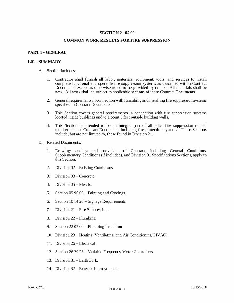
SECTION 21 05 00
COMMON WORK RESULTS FOR FIRE SUPPRESSION
PART 1 - GENERAL
1.01 SUMMARY
A. Section Includes:
1. Contractor shall furnish all labor, materials, equipment, tools, and services to install complete functional and operable fire suppression systems as described within Contract Documents, except as otherwise noted to be provided by others. All materials shall be new. All work shall be subject to applicable sections of these Contract Documents.
2. General requirements in connection with furnishing and installing fire suppression systems specified in Contract Documents.
3. This Section covers general requirements in connection with fire suppression systems located inside buildings and to a point 5 feet outside building walls.
4. This Section is intended to be an integral part of all other fire suppression related requirements of Contract Documents, including fire protection systems. These Sections include, but are not limited to, those found in Division 21.
B. Related Documents:
1. Drawings and general provisions of Contract, including General Conditions, Supplementary Conditions (if included), and Division 01 Specifications Sections, apply to this Section.
2. Division 02 – Existing Conditions.
3. Division 03 – Concrete.
4. Division 05 – Metals.
5. Section 09 96 00 – Painting and Coatings.
6. Section 10 14 20 – Signage Requirements
7. Division 21 – Fire Suppression.
8. Division 22 – Plumbing
9. Section 22 07 00 – Plumbing Insulation
10. Division 23 – Heating, Ventilating, and Air Conditioning (HVAC).
11. Division 26 – Electrical
12. Section 26 29 23 – Variable Frequency Motor Controllers
13. Division 31 – Earthwork.
14. Division 32 – Exterior Improvements.
1641027.0 10/15/2018
21 05 00 - 2
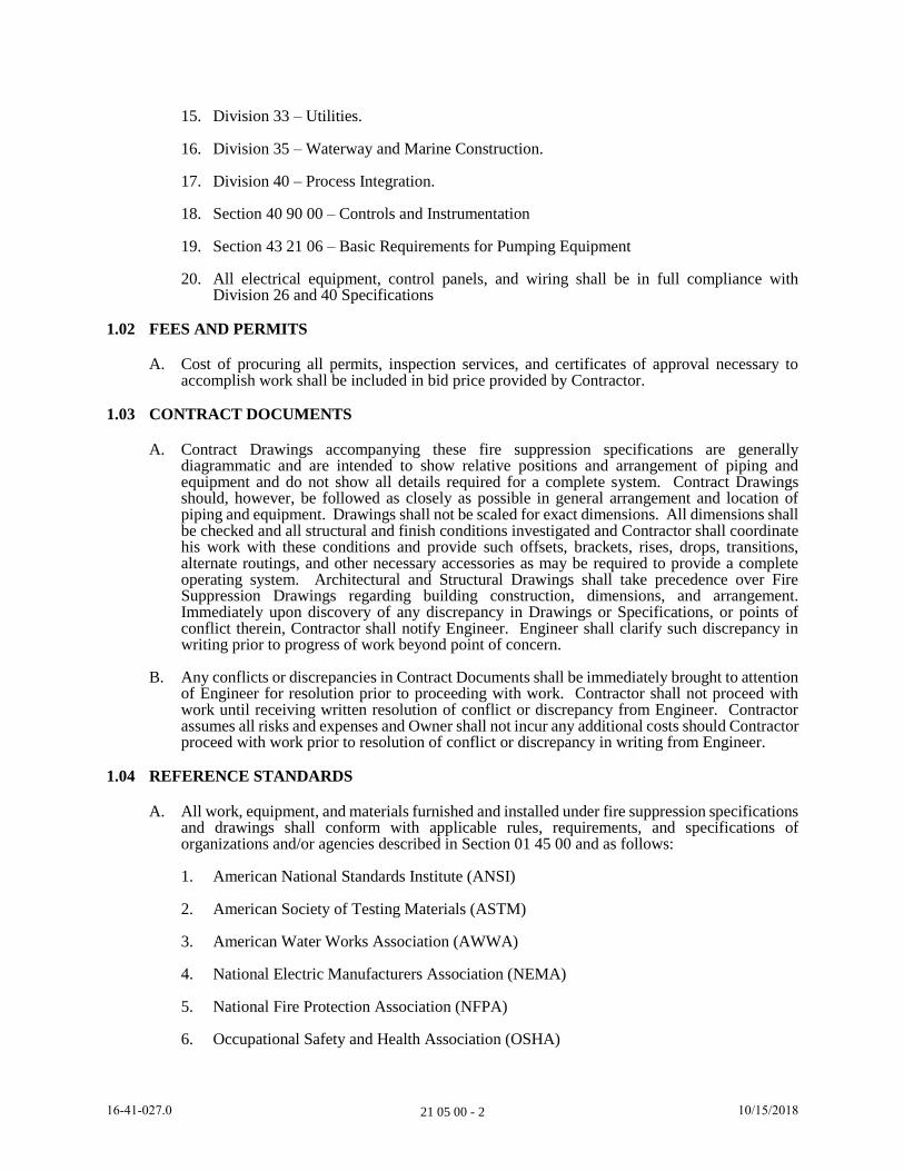
15. Division 33 – Utilities.
16. Division 35 – Waterway and Marine Construction.
17. Division 40 – Process Integration.
18. Section 40 90 00 – Controls and Instrumentation
19. Section 43 21 06 – Basic Requirements for Pumping Equipment
20. All electrical equipment, control panels, and wiring shall be in full compliance with Division 26 and 40 Specifications
1.02 FEES AND PERMITS
A. Cost of procuring all permits, inspection services, and certificates of approval necessary to accomplish work shall be included in bid price provided by Contractor.
1.03 CONTRACT DOCUMENTS
A. Contract Drawings accompanying these fire suppression specifications are generally diagrammatic and are intended to show relative positions and arrangement of piping and equipment and do not show all details required for a complete system. Contract Drawings should, however, be followed as closely as possible in general arrangement and location of piping and equipment. Drawings shall not be scaled for exact dimensions. All dimensions shall be checked and all structural and finish conditions investigated and Contractor shall coordinate his work with these conditions and provide such offsets, brackets, rises, drops, transitions, alternate routings, and other necessary accessories as may be required to provide a complete operating system. Architectural and Structural Drawings shall take precedence over Fire Suppression Drawings regarding building construction, dimensions, and arrangement. Immediately upon discovery of any discrepancy in Drawings or Specifications, or points of conflict therein, Contractor shall notify Engineer. Engineer shall clarify such discrepancy in writing prior to progress of work beyond point of concern.
B. Any conflicts or discrepancies in Contract Documents shall be immediately brought to attention of Engineer for resolution prior to proceeding with work. Contractor shall not proceed with work until receiving written resolution of conflict or discrepancy from Engineer. Contractor assumes all risks and expenses and Owner shall not incur any additional costs should Contractor proceed with work prior to resolution of conflict or discrepancy in writing from Engineer.
1.04 REFERENCE STANDARDS
A. All work, equipment, and materials furnished and installed under fire suppression specifications and drawings shall conform with applicable rules, requirements, and specifications of organizations and/or agencies described in Section 01 45 00 and as follows:
1. American National Standards Institute (ANSI)
2. American Society of Testing Materials (ASTM)
3. American Water Works Association (AWWA)
4. National Electric Manufacturers Association (NEMA)
5. National Fire Protection Association (NFPA)
6. Occupational Safety and Health Association (OSHA)
1641027.0 10/15/2018
21 05 00 - 3
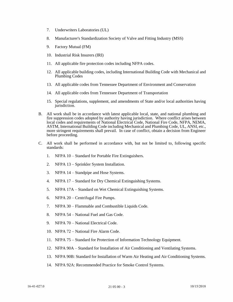
7. Underwriters Laboratories (UL)
8. Manufacturer's Standardization Society of Valve and Fitting Industry (MSS)
9. Factory Mutual (FM)
10. Industrial Risk Insurers (IRI)
11. All applicable fire protection codes including NFPA codes.
12. All applicable building codes, including International Building Code with Mechanical and Plumbing Codes
13. All applicable codes from Tennessee Department of Environment and Conservation
14. All applicable codes from Tennessee Department of Transportation
15. Special regulations, supplement, and amendments of State and/or local authorities having jurisdiction.
B. All work shall be in accordance with latest applicable local, state, and national plumbing and fire suppression codes adopted by authority having jurisdiction. Where conflict arises between local codes and requirements of National Electrical Code, National Fire Code, NFPA, NEMA, ASTM, International Building Code including Mechanical and Plumbing Code, UL, ANSI, etc., more stringent requirements shall prevail. In case of conflict, obtain a decision from Engineer before proceeding.
C. All work shall be performed in accordance with, but not be limited to, following specific standards:
1. NFPA 10 – Standard for Portable Fire Extinguishers.
2. NFPA 13 – Sprinkler System Installation.
3. NFPA 14 – Standpipe and Hose Systems.
4. NFPA 17 – Standard for Dry Chemical Extinguishing Systems.
5. NFPA 17A – Standard on Wet Chemical Extinguishing Systems.
6. NFPA 20 – Centrifugal Fire Pumps.
7. NFPA 30 – Flammable and Combustible Liquids Code.
8. NFPA 54 – National Fuel and Gas Code.
9. NFPA 70 – National Electrical Code.
10. NFPA 72 – National Fire Alarm Code.
11. NFPA 75 – Standard for Protection of Information Technology Equipment.
12. NFPA 90A – Standard for Installation of Air Conditioning and Ventilating Systems.
13. NFPA 90B: Standard for Installation of Warm Air Heating and Air Conditioning Systems.
14. NFPA 92A: Recommended Practice for Smoke Control Systems.
1641027.0 10/15/2018

21 05 00 - 4
15. NFPA 92B: Guide for Smoke Management Systems in Malls, Atria, and Large Areas.
16. NFPA 101 – Life Safety Code.
17. NFPA 105: Recommended Practice for Installation of Smoke Control Door Assemblies.
18. NFPA 230: Standard for Fire Protection of Storage.
19. NFPA 241: Standard for Safeguarding Building Construction, Alteration and Demolition Operations.
20. ANSI Handicapped Code-A117.1.
21. U.L. Fire Resistance Index.
22. ASTM E814-08B: Standard Test Method for Fire Tests of Penetration Firestop Systems.
23. IBC – International Building Code, with Mechanical and Plumbing Codes.
1.05 SUBMITTALS
A. All submittals shall be provided in accordance with Section 01 33 00.
B. Shop drawings, product data, and catalog cuts shall be submitted in accordance with Section 01 33 00 for items so designated in fire suppression portions of Contract Documents and so designated in Section 01 61 00.
C. Submittals shall be provided for each fire suppression specification section in Division 21.
D. Upon completion of work, Contractor shall obtain all certificate(s) of inspection and approval from inspection organization having jurisdiction and shall deliver same to Engineer.
E. Group submittals to include complete information of related systems, products, and accessories in a single submittal.
F. Prepare coordinated room layouts as described herein and as specified in Section 01 31 13 and in accordance with Section 01 33 00. Include coordination of concrete pads and foundations including anchor bolt and sleeve locations.
1.06 PROJECT/SITE CONDITIONS
A. Work shall be in accordance with Sections 01 11 13 and 01 31 13.
B. Coordinate work with other trades and with measurements obtained at job site, as applicable, prior to installation.
C. If prevented by project conditions, prepare drawings and other necessary documents showing proposed rearrangement of Work, including changes to Work specified in other sections, and submit to Engineer for review and approval in accordance with Section 01 33 00. Engineer shall provide written direction prior to Contractor progressing with work beyond point of concern or proceeding with any changes.
D. Place anchors, sleeves, and supports prior to pouring concrete or installation of masonry work. Coordinate work with other trades.
E. Cause as little interference or interruption of existing utilities and services as possible. Schedule work which shall cause interference or interruption in advance with Owner and all affected trades, and as necessary authority having jurisdiction. Comply with Section 01 11 13.
1641027.0 10/15/2018
21 05 00 - 5
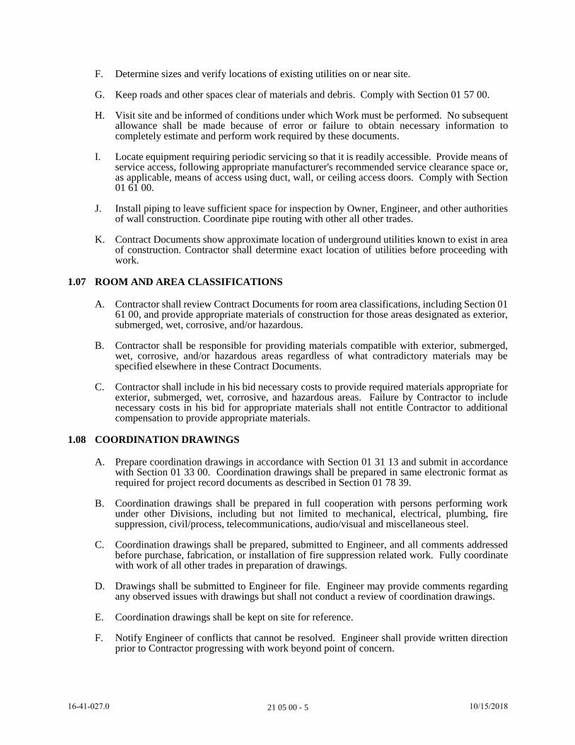
F. Determine sizes and verify locations of existing utilities on or near site.
G. Keep roads and other spaces clear of materials and debris. Comply with Section 01 57 00.
H. Visit site and be informed of conditions under which Work must be performed. No subsequent allowance shall be made because of error or failure to obtain necessary information to completely estimate and perform work required by these documents.
I. Locate equipment requiring periodic servicing so that it is readily accessible. Provide means of service access, following appropriate manufacturer's recommended service clearance space or, as applicable, means of access using duct, wall, or ceiling access doors. Comply with Section 01 61 00.
J. Install piping to leave sufficient space for inspection by Owner, Engineer, and other authorities of wall construction. Coordinate pipe routing with other all other trades.
K. Contract Documents show approximate location of underground utilities known to exist in area of construction. Contractor shall determine exact location of utilities before proceeding with work.
1.07 ROOM AND AREA CLASSIFICATIONS
A. Contractor shall review Contract Documents for room area classifications, including Section 01 61 00, and provide appropriate materials of construction for those areas designated as exterior, submerged, wet, corrosive, and/or hazardous.
B. Contractor shall be responsible for providing materials compatible with exterior, submerged, wet, corrosive, and/or hazardous areas regardless of what contradictory materials may be specified elsewhere in these Contract Documents.
C. Contractor shall include in his bid necessary costs to provide required materials appropriate for exterior, submerged, wet, corrosive, and hazardous areas. Failure by Contractor to include necessary costs in his bid for appropriate materials shall not entitle Contractor to additional compensation to provide appropriate materials.
1.08 COORDINATION DRAWINGS
A. Prepare coordination drawings in accordance with Section 01 31 13 and submit in accordance with Section 01 33 00. Coordination drawings shall be prepared in same electronic format as required for project record documents as described in Section 01 78 39.
B. Coordination drawings shall be prepared in full cooperation with persons performing work under other Divisions, including but not limited to mechanical, electrical, plumbing, fire suppression, civil/process, telecommunications, audio/visual and miscellaneous steel.
C. Coordination drawings shall be prepared, submitted to Engineer, and all comments addressed before purchase, fabrication, or installation of fire suppression related work. Fully coordinate with work of all other trades in preparation of drawings.
D. Drawings shall be submitted to Engineer for file. Engineer may provide comments regarding any observed issues with drawings but shall not conduct a review of coordination drawings.
E. Coordination drawings shall be kept on site for reference.
F. Notify Engineer of conflicts that cannot be resolved. Engineer shall provide written direction prior to Contractor progressing with work beyond point of concern.
1641027.0 10/15/2018
21 05 00 - 6
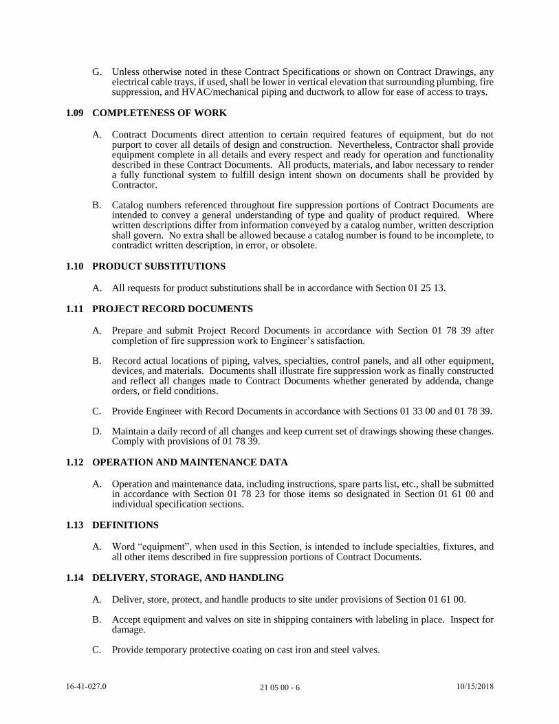
G. Unless otherwise noted in these Contract Specifications or shown on Contract Drawings, any electrical cable trays, if used, shall be lower in vertical elevation that surrounding plumbing, fire suppression, and HVAC/mechanical piping and ductwork to allow for ease of access to trays.
1.09 COMPLETENESS OF WORK
A. Contract Documents direct attention to certain required features of equipment, but do not purport to cover all details of design and construction. Nevertheless, Contractor shall provide equipment complete in all details and every respect and ready for operation and functionality described in these Contract Documents. All products, materials, and labor necessary to render a fully functional system to fulfill design intent shown on documents shall be provided by Contractor.
B. Catalog numbers referenced throughout fire suppression portions of Contract Documents are intended to convey a general understanding of type and quality of product required. Where written descriptions differ from information conveyed by a catalog number, written description shall govern. No extra shall be allowed because a catalog number is found to be incomplete, to contradict written description, in error, or obsolete.
1.10 PRODUCT SUBSTITUTIONS
A. All requests for product substitutions shall be in accordance with Section 01 25 13.
1.11 PROJECT RECORD DOCUMENTS
A. Prepare and submit Project Record Documents in accordance with Section 01 78 39 after completion of fire suppression work to Engineer’s satisfaction.
B. Record actual locations of piping, valves, specialties, control panels, and all other equipment, devices, and materials. Documents shall illustrate fire suppression work as finally constructed and reflect all changes made to Contract Documents whether generated by addenda, change orders, or field conditions.
C. Provide Engineer with Record Documents in accordance with Sections 01 33 00 and 01 78 39.
D. Maintain a daily record of all changes and keep current set of drawings showing these changes. Comply with provisions of 01 78 39.
1.12 OPERATION AND MAINTENANCE DATA
A. Operation and maintenance data, including instructions, spare parts list, etc., shall be submitted in accordance with Section 01 78 23 for those items so designated in Section 01 61 00 and individual specification sections.
1.13 DEFINITIONS
A. Word “equipment”, when used in this Section, is intended to include specialties, fixtures, and all other items described in fire suppression portions of Contract Documents.
1.14 DELIVERY, STORAGE, AND HANDLING
A. Deliver, store, protect, and handle products to site under provisions of Section 01 61 00.
B. Accept equipment and valves on site in shipping containers with labeling in place. Inspect for damage.
C. Provide temporary protective coating on cast iron and steel valves.
1641027.0 10/15/2018
21 05 00 - 7
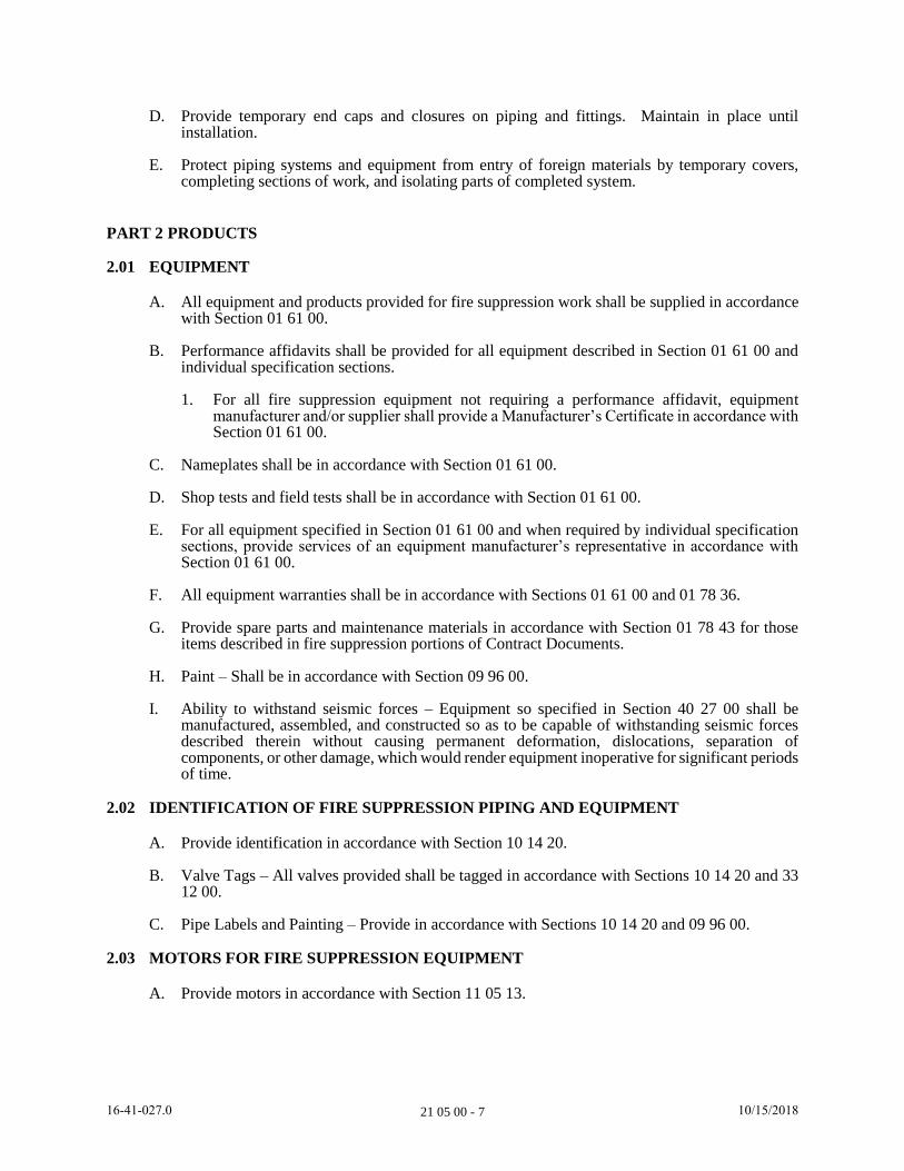
D. Provide temporary end caps and closures on piping and fittings. Maintain in place until installation.
E. Protect piping systems and equipment from entry of foreign materials by temporary covers, completing sections of work, and isolating parts of completed system.
PART 2 PRODUCTS
2.01 EQUIPMENT
A. All equipment and products provided for fire suppression work shall be supplied in accordance with Section 01 61 00.
B. Performance affidavits shall be provided for all equipment described in Section 01 61 00 and individual specification sections.
1. For all fire suppression equipment not requiring a performance affidavit, equipment manufacturer and/or supplier shall provide a Manufacturer’s Certificate in accordance with Section 01 61 00.
C. Nameplates shall be in accordance with Section 01 61 00.
D. Shop tests and field tests shall be in accordance with Section 01 61 00.
E. For all equipment specified in Section 01 61 00 and when required by individual specification sections, provide services of an equipment manufacturer’s representative in accordance with Section 01 61 00.
F. All equipment warranties shall be in accordance with Sections 01 61 00 and 01 78 36.
G. Provide spare parts and maintenance materials in accordance with Section 01 78 43 for those items described in fire suppression portions of Contract Documents.
H. Paint – Shall be in accordance with Section 09 96 00.
I. Ability to withstand seismic forces – Equipment so specified in Section 40 27 00 shall be manufactured, assembled, and constructed so as to be capable of withstanding seismic forces described therein without causing permanent deformation, dislocations, separation of components, or other damage, which would render equipment inoperative for significant periods of time.
2.02 IDENTIFICATION OF FIRE SUPPRESSION PIPING AND EQUIPMENT
A. Provide identification in accordance with Section 10 14 20.
B. Valve Tags – All valves provided shall be tagged in accordance with Sections 10 14 20 and 33 12 00.
C. Pipe Labels and Painting – Provide in accordance with Sections 10 14 20 and 09 96 00.
2.03 MOTORS FOR FIRE SUPPRESSION EQUIPMENT
A. Provide motors in accordance with Section 11 05 13.
1641027.0 10/15/2018
21 05 00 - 8
2.04 VARIABLE FREQUENCY DRIVES FOR FIRE SUPPRESSION EQUIPMENT
A. Provide drives in accordance with Section 26 29 23.
2.05 PIPE SLEEVES, INSERTS, AND FLASHING
A. Openings, chases, sleeves, and inserts shall comply with Section 01 31 13.
B. All piping passing through walls, floors, ceilings, and roof decks shall be installed in sleeves accurately located before concrete is poured, or placed in position during construction of masonry walls, roofs, and other structures. Sleeves shall be sized in accordance with manufacturer’s recommendations, but in no case shall annular space between sleeve and pipe be less than 1/2 inch in order to accommodate seal described herein and shall be larger as required for required seal system utilized. Pipe sleeves, except for those passing through structural members, shall be 18 gauge galvanized iron. Pipe sleeves passing through structural members shall be Schedule 40 steel. Sleeves passing through floors shall extend from bottom of floor to a point 3 inches above finished floor, unless shown otherwise; sleeves shall be flush with underside of floor. Sleeves passing through walls shall be flush with both sides of wall. All steel wall and floor sleeves shall receive a commercial sandblast cleaning and only surfaces not in contact with concrete shall be painted, in accordance with Section 09 96 00.
C. Contractor shall confirm layouts before work begins in those areas.
D. Watertight sleeves shall be furnished for all pipes passing through floors or walls which are continually wet, under hydrostatic pressure, or below grade.
E. Sleeves shall be in accordance with details shown on C-, X-, or D-, Drawings. If not shown on Drawings, Contractor shall submit to Engineer details of sleeves proposed for installation, and no fabrication or installation thereof shall take place until Engineer’s approval is obtained. Contractor shall coordinate location and setting of sleeve with other trades.
1. Unless details provided on Drawings differ, sleeves supporting riser piping 4 inches and larger shall have three 6-inch long reinforcing rods welded radically at 120 degree spacing to sleeve and shall be installed with rods embedded in concrete slab.
F. Annular space between installed piping and sleeve shall be completely sealed against a maximum hydrostatic (or gas) pressure of 20 psig with a modular mechanical type seal consisting of interlocking synthetic rubber links connected by Type 316 stainless steel bolts and nuts with pressure plates under each end. Tightening bolts shall compress neoprene lines causing them to expand and form a continuous, air tight, watertight seal between pipe and sleeve. Seal shall be "Link-Seal", as manufactured by Thunderline Corporation, Wayne Michigan, or equal. Seal type, size, and installation thereof shall be in strict accordance with manufacturer’s recommendations. In general, sleeves installed in walls or floors against one side of which shall develop a hydrostatic or gas pressure, or through which leakage of liquid shall occur, shall be so sealed. Seals shall be provided for all piping passing through walls between explosion-proof and non explosion-proof areas. Refer to standard details as shown on Contract Drawings for wall, floor, and deck sleeve details.
1. If necessary, provide alternate seals that meet required firestopping requirements.
G. Flashing and Counter-flashing.
1. Furnish materials and coordinate installation for flashing and counter flashing roof penetrations for vents, pipe, drains, ducts, and all other penetrations.
2. Materials:
a. Sheetmetal: 24 gauge minimum ASTM A525, Class G90.
1641027.0 10/15/2018

21 05 00 - 9
b. Sheet lead: 3 pounds per square foot.
c. Stainless steel: Minimum 20-gauge.
d. Sheet copper: 24 OZ/SF.
e. Vent Stack Fitting: Josam 1830 or Jay R. Smith 1750
3. Flashing shall extend into roof on all sides of sleeve. Flashing sleeves shall be coordinated with roof system.
H. Sleeves through fire/smoke walls and floors shall be installed per NFPA and seal all cracks and voids with fireproof sealant.
I. Install piping, insulation and sleeves in strict accordance with applicable U.L. Fire Resistance Index assembly and with firestop manufacturer’s installation instructions for floor and partition penetrations. Coordinate with Division 07.
J. Penetrations not sleeved or firestopped – All penetrations shall be sleeved, and firestopped where applicable. Seals shall be air-tight.
K. Escutcheon Plates – Provide B & C No. 10 or equal chrome plated escutcheon plates where exposed un-insulated pipes penetrate partitions, floors, walls, or ceilings in finished areas.
1. Mechanical rooms, store rooms, electric closets, and janitor closets are not considered "finished" spaces.
2. Clearance between sleeve and pipe – Minimum 1/2 inch for hot piping and 1 inch for cold piping or as otherwise dictated by U.L. Fire Resistance Directory.
2.06 EQUIPMENT PADS AND ANCHORS
A. Equipment and housekeeping pads shall be in accordance with Sections 01 31 13, 01 61 00, 05 56 00 and 40 27 00, and Division 03.
B. Contractor shall provide 4-inch high concrete pads for supporting floor-mounted equipment, including setting of anchor bolts, sleeves, and cradles.
C. Furnish anchor bolts, sleeves, cradles, and provide dimensional layouts as necessary for this purpose. Contractor shall confirm all layouts before pad(s) are poured.
2.07 FABRICATION REQUIREMENTS
A. Painting, including surface preparation, shall be in accordance with Section 09 96 00.
B. Factory finishes on equipment shall be maintained in good condition, free from rust, abrasions, and dents. Field touch-up painting and other minor repairs shall be performed in accordance with equipment manufacturer’s instructions and requirements and recommendations by Contractor.
2.08 HANGERS, ANCHORS, AND SUPPORTS
A. Hangers, anchors, and supports shall be in accordance with Sections 40 27 00 and 01 61 00.
B. Provide seismic restraints as required for seismic zone classification for location of work. Extent of requirements shall be determined by Engineer providing support design as defined in Section 40 27 00.
1641027.0 10/15/2018
21 05 00 - 10
C. Design of hanger, anchors, and supports for fire suppression systems shall be accomplished by a State of Tennessee licensed professional engineer engaged by Contractor in accordance with these Contract Documents, including Section 40 27 00.
2.09 WALL AND CEILING ACCESS PANELS AND DOORS
A. Wall and ceiling access doors – install under provisions of Division 08 and as specified herein.
B. Wall and ceiling access panels.
1. Style and type as required for material in which installed.
2. Size: 24-inch x 24-inch minimum, as indicated, or as required to allow inspection, service and removal of items served.
3. 14-gauge minimum sheet metal for doors, 16 gauge frames of cadmium-plated or galvanized construction. Doors shall have expanded plaster rings where located in plaster walls or flanged finish where located in drywall or block construction.
4. Panels shall have spring hinges with screwdriver locks in non-public areas. Key lock, keyed alike, for panels in public areas.
5. Prime painted or rust inhibitive paint finish.
6. UL labeled when in fire-rated construction, 1-1/2 hour rating.
7. Provide in walls, floors, and ceilings to permit access to all equipment and piping requiring service or adjustment. Examples of such equipment needing access are valves, and equipment needing periodic or replacement maintenance.
8. Furnish and locate access panels under this Division. Coordinate with trades who are responsible for building system in which panels are to be installed.
9. Acceptable manufactures: Milcor, Nystrom, Karp, J.L. Industries, or Williams Brothers.
a. For masonry and drywall construction: Milcor Style M.
b. For plastered masonry walls and ceiling: Milcor Style K.
c. For ceramic tile or glazed structural tile: Use stainless steel panels.
2.10 PIPE ENCLOSURES
A. Minimize number of covers by enclosing maximum number of pipes in each drop.
B. Anchor to equipment or partition.
C. Fasten seams and joints with stainless steel pop rivets.
D. Provide 1-1/2-inch ceiling flange at closure.
2.11 CONTROLS AND EQUIPMENT PANELS
A. All controls and equipment panels shall comply fully with Divisions 26 and 40, including Section 40 90 00.
B. All control panels, disconnects, isolation switches, junction and control boxes, and any other type of enclosure for electrical and control equipment shall be rated NEMA 4X corrosion
1641027.0 10/15/2018

21 05 00 - 11
resistant unless located in an interior area rated as an “unclassified area” per Section 01 61 00. This statement shall take precedence over any other requirements described in these Contract Documents.
PART 3 EXECUTION
3.01 COORDINATION
A. Contractor shall coordinate his work with that of his subcontractors. Contractor’s subcontractors shall provide information for setting sleeves, inserts, anchors, equipment pads, and advise Contractor of all opening sizes, and supply all items to be installed by Contractor in ample time. Do not rough in equipment without an approved shop drawing.
B. All wiring shall be done by Contractor or Electrical Subcontractor. Contractor’s subcontractors shall advise Contractor of all requirements in ample time. All motor starters, controllers, etc., shall be provided by Contractor or Electrical Subcontractor unless otherwise noted. All motors supplied with equipment shall conform to Section 11 05 13 and Division 26 unless otherwise noted.
C. Final piping connections between fire suppression systems and equipment or systems provided by others shall be made by Contractor or his fire suppression subcontractor.
D. All coordination shall be in accordance with Sections 01 31 13, 01 45 00 and 01 61 00.
E. All temporary construction facilities, utilities, and controls shall be provided in accordance with Sections 01 51 00 and 01 57 00.
F. Any demolition activities shall be in accordance with Section 02 41 00.
G. Any required site preparation and clearing activities shall be performed in accordance with Section 31 11 00.
H. Existing facilities shall be protected in accordance with Section 01 76 00.
3.02 EXCAVATION, BACKFILL, AND COMPACTION
A. All erosion and sediment control measures, in accordance with Section 01 57 29, shall be in place before any excavation activities commence.
B. All excavation, trenching, and grading shall be performed in accordance with Section 31 23 16.
C. Bedding, backfilling, and compaction shall be performed in accordance with Section 31 23 23, unless under paving, in which case work shall be performed in accordance with Section 32 11 00.
D. Any required pavement cutting shall be performed in accordance with Section 32 12 83.
E. Any removal of water operations necessary to accomplish work shall be performed in accordance with Section 31 23 19.
F. Contractor shall provide necessary sheeting and bracing to accomplish work in accordance with Section 31 50 00.
G. Any rock removal operations shall be performed in accordance with Section 31 23 17.
H. Any pavement replacement shall be in accordance with Sections 32 12 00, 32 14 23, 32 17 23, and Contract Drawings.
1641027.0 10/15/2018

21 05 00 - 12
I. Any concrete curbs, gutters, or sidewalks shall be repaired in accordance with Section 32 16 13 and Contract Drawings.
J. Any necessary site rehabilitation shall be performed in accordance with Section 32 90 00.
K. Clean and inspect pipe for defects before lowering into trench for assembly. Install pipe in accordance with provisions of Contract Documents and recommendations of pipe manufacturer including Sections 33 11 00 and 33 12 00.
1. Ensure pipe is of proper strength and classification for specified service. Discard damaged or defective pipe discovered during pipe laying operations.
2. Maintain alignment and grade during layout operation. Use acceptable method for maintaining grade and alignment to produce desired results.
3. Trenches shall be backfilled only after piping has been inspected, tested, and approved by Engineer.
3.03 BYPASS PUMPING
A. Any required bypass pumping operations necessary to accomplish work shall be provided in accordance with Section 01 57 53.
3.04 CUTTING AND PATCHING
A. All cutting and patching necessary to accomplish fire suppression work shall be in accordance with Section 01 31 13.
3.05 INSTALLATION
A. Fire suppression equipment shall be installed in accordance with manufacturer’s instructions and as required by NFPA.
B. Equipment and piping shall be secured in position in an approved workmanlike manner with suitable supports, anchors, and hangers in accordance with Section 40 27 00 and as necessary, with concealed hangers and carriers.
C. Fasteners on underside of precast/prestressed concrete members (planks or double tees) which serve for direct attachment or for hangers of mechanical/electrical equipment, piping, ducting, etc., may not be drilled in or shot in vicinity of prestressing tendons. This means that fasteners at concrete planks can be placed only at joints between units. Any intermediate supports needed to accomplish this shall be provided by Contractor. If template or tendon location is obtained from manufacturer of planks, intermediate attachments can be allowed for special cases. Heavy loads must be carried by through-bolts which must be installed before roofing is applied.
D. Equipment and piping shall be kept free of dirt. Pipe openings shall be protected by caps, plugs, or other suitable means. Equipment shall be covered and protected against dirt, water, and chemical or mechanical damage.
E. Pipe insulation shall be furnished and installed in accordance with Division 21, 22, and 40.
F. All equipment installations shall be in accordance with Sections 01 31 13, 01 45 00, and 01 61 00.
G. All equipment shall be free from imperfections, true as to line, angles, curves and color, smooth, watertight, complete in every respect.
1641027.0 10/15/2018
21 05 00 - 13
H. Contractor shall be responsible for guaranteeing proper selection and coordination of all fittings and parts relating to each piece of equipment.
I. Water supplies to all equipment shall be valved at equipment.
J. All equipment shall be left thoroughly clean and free from all marks and foreign substances.
K. Contractor shall replace all leaking equipment prior to final inspection.
L. Locate valves so as to be easily accessible by maintenance personnel.
3.06 EQUIPMENT GUARDS
A. Use suitable structural frames with minimum 12 gauge, 3/4-inch galvanized mesh, or expanded metal mesh. Attach to equipment by removable clips and bolts with wing nuts, or other approved connectors.
B. At belts, provide opening for measuring RPMs.
C. Provide at all belts, couplings, moving machinery and equipment.
D. Design for easy access to belts and other items requiring replacement.
E. Comply with OSHA regulations.
3.07 PROJECT CLOSEOUT
A. All project closeout procedures shall be in accordance with Section 01 77 00.
3.08 CLEANING
A. All cleaning shall be in accordance with Section 01 77 00.
B. Cleaning shall be required for all equipment, fixtures, piping, and accessories, including but not limited to, following:
1. Removal and cleaning of all debris from trenches, crawl spaces, ceilings, and other unoccupied spaces.
2. Removal and cleaning of all filters, strainers, drains, and traps. Those items that cannot be fully cleaned shall be replaced by Contractor at his expense.
3. Cleaning of all valve seats.
4. Removal of labels, protective coatings, and wrappings.
5. Removal of grease and dirt from finished surfaces.
6. Repair of minor dents and scratches from damaged equipment. Major dents, as determined by Engineer, may necessitate replacement of equipment with a new unit at discretion of Engineer.
C. General Cleanup.
1. Upon completion of contract and progressively as work proceeds, clean up dirt, debris, scrap materials, etc., and remove from site, keeping premises in neat and clean condition to satisfaction of Engineer and Owner.
1641027.0 10/15/2018
21 05 00 - 14
2. Seepage, discoloration or other damage to parts of building, its finish, or furnishings due to Contractor's failure to properly clean piping systems or duct systems shall be repaired without cost to Owner.
D. Protect and preserve access to all energized equipment at all times.
E. Factory Finishes – Clean items with factory finishes. Touch up bare places, scratches and other minor damage to finishes. Use only factory supplied paint of matching color and formula. If finishes are badly damaged or if there are many damaged, scratched or bare places, refinish entire item.
F. Fire Suppression System – See Section 21 13 13.
1. Flush system progressively by opening building operable valves, faucets and hose bibs and permitting flow to continue from each unit until water runs clear. Clean all gauge glasses, strainers, valve seats, etc.
2. Disinfect system in accordance with requirements of Section 33 13 00 and local authority having jurisdiction.
3. Have local authority having jurisdiction check and approve system before connecting it to existing water system.
3.09 STARTUP AND TESTING
A. All startups and testing shall be in accordance with Sections 01 45 29, 01 61 00, 01 88 23, and 01 88 26 and any special requirements for fire suppression systems as described in Contract Documents.
B. Test all systems and equipment installed to demonstrate proper operation.
C. Advise Owner, local fire marshal, and Engineer of scheduled systems testing and completed system demonstration/operation schedules so that he may witness, if desired.
D. Promptly correct and retest work found defective when tested.
E. Promptly make repairs to piping systems with new materials. Peening, doping, or caulking of joints or holes shall not be acceptable.
F. All testing and adjustments shall be completed to satisfaction of Engineer prior to review and final acceptance by local inspection authorities.
G. Pressure Testing – See Section 21 13 13.
1. Testing shall be in accordance with Section 33 13 00 except as modified herein.
2. Fire Suppression System Piping – Test hot and cold water piping systems upon completion of rough-in, before fixtures are connected, at a hydrostatic pressure of 125 psig or 150 percent of working pressure whichever is greater for a period of two hours.
3. Any leaks or ruptured piping disclosed by tests shall be repaired or replaced, and test repeated to Engineer’s satisfaction.
H. Testing.
1. All water for tests shall be furnished and disposed of by Contractor at his expense. Source and/or quality of water which Contractor proposes to use in testing shall be acceptable to Engineer.
1641027.0 10/15/2018
21 05 00 - 15
I. Certification of equipment compliance – When required by Section 01 61 00 or individual specification sections, manufacturer’s representative shall submit written certification from equipment manufacturers jointly to Owner, Engineer and Contractor that equipment supplied or manufactured by their organization has been installed and tested to their satisfaction, and that all final adjustments thereto have been made. Certification shall include date of final acceptance field test, as well as a listing of all persons present during tests. See “Equipment Start-Up Report and Certification” in Section 01 99 00.
END OF SECTION
1641027.0 10/15/2018