addendum - caspar building systems · this addendum number one dated thursday september 8, ......
TRANSCRIPT

Page 1 of 8 15-015/Documents/313_ Addendum 01_09-08-16
ADDENDUM
PROJECT: DAVID STREET STATION 200 SOUTH DAVID STREET CASPER, WYOMING 82601
ADDENDUM NUMBER TWO This addendum number one dated Thursday September 8, 2016 is hereby appended to and became a part of the Contract Documents for the David Street Station, 200 South David Street, Casper, Wyoming. Drawings and specifications dated May 10th, 2016. GENERAL
CHANGE: The contact information for the below general contractor:
COMPANY CITY, ST PHONE FAX Sampson Construction Cheyenne, WY 307-426-4050 307-426-4051
Mid-Valley General Contractors Riverton, WY 307-856-3421 307-857-4041 ARCHITECTURAL DRAWINGS
General
CLARIFY: “1 x reclaimed Snow fence” noted on the drawings to be 1x Wyoming recycled snow fence as supplied by Centennial Woods, Laramie, Wyoming.
CLARIFY: For clear powder coat finished noted on the drawings, it applies to base bid and
all alternates. A mill steel finish beneath the clear powder coat finish is desired; protect steel from weathering so that minimal rust removal is required prior to powder coat application and use non-mechanical means for rust removal.
Sheet 0.20
CLARIFY: In the event Alternates # 2 and/or # 3 are not accepted, the contractor is to
clear/level the area of Alternate #2 and #3 in preparation for owner-provided seeding.
Sheet 0.20 and 1.05
CLARIFY: Alternate #2 and Alternate #3 are stand-alone; do not include one alternate within
the other. Alternate #2 has been designed so the remainder of the work in Alternate #3 will create a fully complete building and systems. For Alternate #3, the contractor shall remove the wood framed roof shown in the Alternate #2.
Sheet 1.90
CLARIFY: Detail 8: Provide 2x wood planks in longest lengths possible. Provide half lap
splice at end-to-end horizontal joints.

Page 2 of 8 15-015/Documents/313_ Addendum 01_09-08-16
ADDENDUM
LANDSCAPE DRAWINGS
General
CLARIFY: Written quantities provided on the plans are for the convenience of the contractor and for owner information, but do not represent maximum actual quantities. Contractor is responsible for providing the quantity of materials necessary to produce the construction shown on the plans.
CLARIFY: Tree protection shall be installed immediately upon initiation of work by the
contractor.
Sheet L-2
CHANGE: The Tree Grate should be identified as the “Chinook 2000”. See the layout plans and Detail 1, Sheet L-24 for where Paver Frames and Standard Frames are required based upon adjacent paving material type.
Sheet L-4
CHANGE: See revised Sheet L-4a attached for clarifications regarding the locations of the
seat walls in Detail 2 “Concrete Edge and Wall at Lawn” on revised Sheet L-22a also attached. Section letter designations have been added to the detail and shown on the plan. In addition, “Section I – Concrete Band” is applicable wherever concrete exists between brick pavers and planters creating a concrete area the width of half of the diagonal of the 24” x 24” promenade post footing formed top.
Sheet L-6
CLARIFY: See revised Sheet L-6a attached for area at trash enclosure that should be designated as Type 1B concrete, increasing the total Type 1B Base Bid area to approximately 1,385 SF (see General Note regarding provided quantities).
CLARIFY: Locations for the nine (9) permanent bollards will be provided by the landscape
architect upon request. CLARIFY: Asphalt surfacing specifications are provided on Sheet 1.01. CHANGE: Text on Sheet L-6 in Misc Surfaces Finish Schedule, Lawn to state: the
Synthetic Lawn shall be “SYNTIPEDE 354 OVER ULTRABASESYSTEMS PROFESSIONAL PANEL” to match the detail on L-22.
No specification is provided for the Synthetic Lawn product. Use specified
manufacturer’s full specification for designated product.

Page 3 of 8 15-015/Documents/313_ Addendum 01_09-08-16
ADDENDUM
CLARIFY: Single bike racks five (5) are only along W. Yellowstone, locations denoted by red arrows in partial sketch below:
Sheet L-10
CHANGE: See revised Sheet L-10a attached for locations of type BL curb. Type P is
indicated on plans as “Flush”
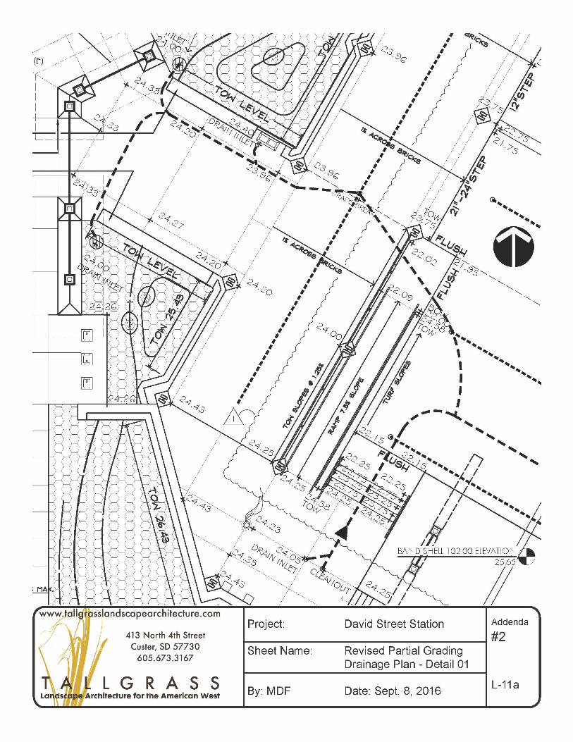
Sheet L-11
CHANGE: See revised sheet L-11a and b attached for additional spot grades around the stage area.
Sheet L-13
CHANGE: Quick Coupler shall be ¾” Rainbird 33-DLRC 3/4" (20/27) Double Track Key
Lug, or equal. See revised Detail 9 Sheet L-29a.
CLARIFY: Both irrigation valves indicated on plan are required. Valve type “XCZ” is mislabeled as “XACZ”. Refer to manufacturer’s standard detail for installation requirements.
CLARIFY: 1 Air Relief Valve is required at high point of mainline (within Phase 1). 1 Drain
Valve is required along each branch of mainline (two (2) in Base Bid, one (1) in Alternate # 3).
CLARIFY: Contractor shall coordinate installation of irrigation water meter and service tap
with the City of Casper (307) 235-8400. City shall provide and install City Water Meter. Contractor is responsible for all other related appurtenances and installation.
CLARIFY: Either Hunter or Rainbird Root watering systems are allowed.

Page 4 of 8 15-015/Documents/313_ Addendum 01_09-08-16
ADDENDUM
Sheet L-14
CLARIFY: Project Tree Schedule: Tree sizes: Multi-stem B&B trees are indicated in tree callouts and shall have a minimum of three trunks with a cumulative caliper of 1-1/2”. Single stem deciduous B&B trees shall have a caliper of 1-1/2” minimum. Evergreen trees shall be measured by height only.
Sheet L-17
CHANGE: See revised sign size and notes on L-17a attached for size and type of material of
the larger signs.
Sheet L-19
CLARIFY: All trench drains shall be “Double Wave” (another type is shown in the detail).
Sheet L-24
CLARIFY: Six (6) waste receptacles shall be provided in the Base Bid. Two (2) shall be provided in Alternate #3.
DELETE: Seasonal rubber mat identified in Detail 80 (to be provided and installed by
owner).
Sheet L-27
CHANGE: See Sheet L-27a attached. Detail 1 has been renamed “48” Stone Wall”. Its location is described in Planter Elevation E on Sheet L-27 and on Sheet L-4.
CHANGE: See Sheet L-27a attached. Detail 4 has been corrected so the lower section is
named “Boulders In Landscape”. Concrete base below boulders is only required where boulder edges are set in concrete.
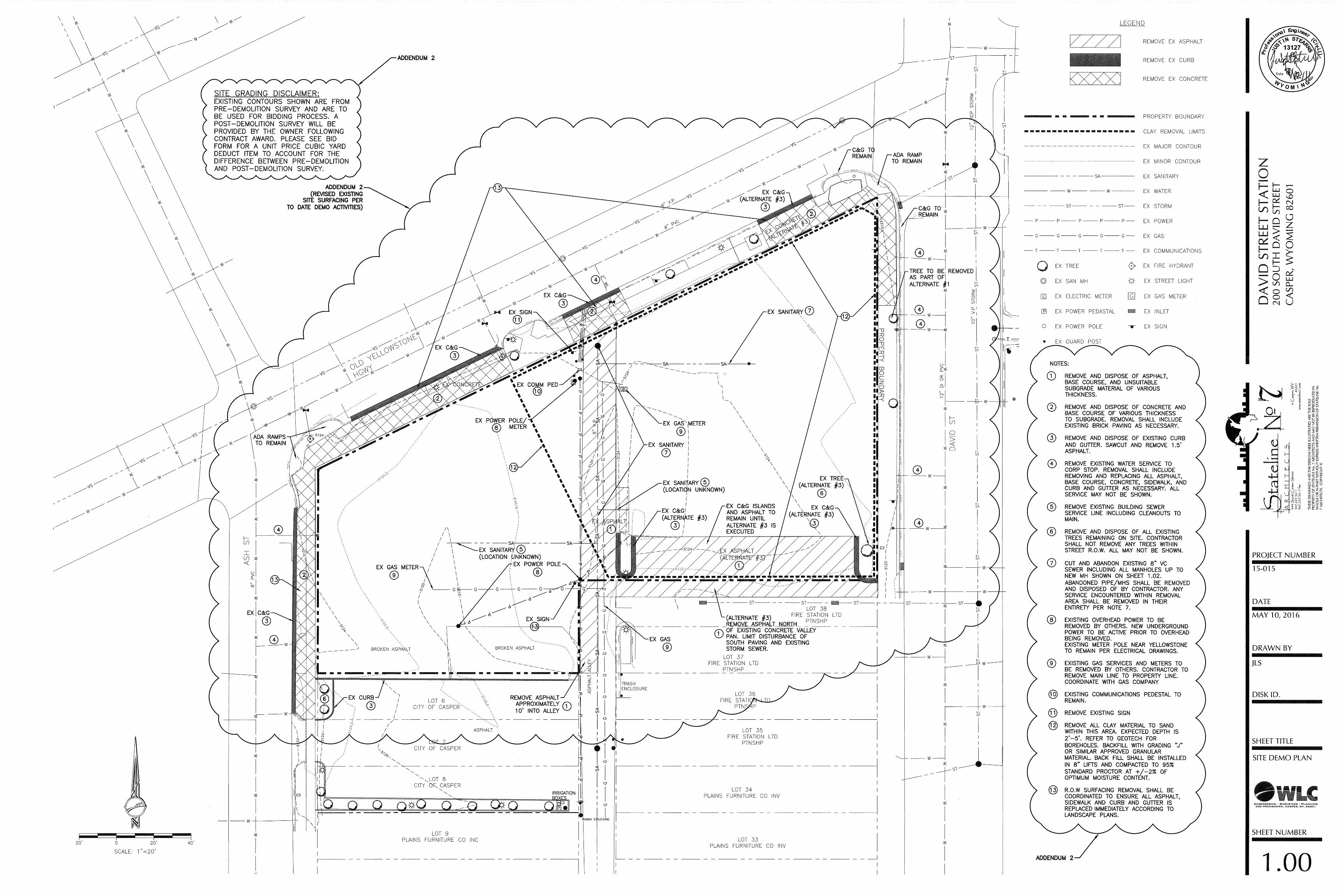
CIVIL DRAWINGS Sheet 1.00
CHANGE: See the clouded areas on the attached Sheet 1.00 for revisions. Sheet 1.03
CHANGE: See the clouded areas on the attached Sheet 1.03 for revisions.

Page 5 of 8 15-015/Documents/313_ Addendum 01_09-08-16
ADDENDUM
STRUCTURAL DRAWINGS Sheet 2.13
CHANGE: GATEWAY FOUNDATION PLANS: At the northeast gateway it has been
determined that the subgrade is not lean concrete as previously thought. The in place soils are sands. However an existing 16” thick foundation wall exists as shown on the attached partial sheet 2.13 that must be partially removed per the attached plan. This wall is unreinforced concrete. The in place sands must be sub-excavated 2’-0” below footing subgrade, moisture conditioned and re-compacted to 95% ASTM D698 density.
Sheet 2.20
CHANGE: GENERAL NOTES: General notes section X-B. Footings are to be placed on
undisturbed native soils. If footing subgrade soils are disturbed they shall be scarified 8” deep, moisture conditioned and re-compacted to 95% ASTM D698 density.
ELECTRICAL DRAWINGS
General
CLARIFY: The electrical contractor shall review all sheets, including architectural, civil, landscaping, splash pad, ice rink, and audio visual for specific electrical items that are not shown on the electrical sheets.
Sheet 16.00
CLARIFY: Flag note 8 refers to the location of the light fixture used for lighting the flag pole. This light fixture is not located on the flag pole and this note does not indicate the location of the flag pole. See the landscape drawings for the flag pole location. The light fixture noted is to be aimed at the flag.
Sheet 16.01
CLARIFY: Per Civil drawing 1.02 the electrical contractor shall refer to the utility company design for layout, quantity, and size of conduit, vaults, transformers, etc. required by the utility company.
SHEET 16.02
CLARIFY: See Civil drawing 1.02 for location of utility pole for telephone service to the building.

Page 6 of 8 15-015/Documents/313_ Addendum 01_09-08-16
ADDENDUM
SPLASH PAD DRAWINGS Sheet 17.12
CLARIFY: Splash Pad Schedule: Item 11: The sentence “All sealant colors are standard colors” has been added to the remarks. Item 12: The sentence “All sealant colors are standard colors” has been added to the remarks. Item 13: The sentence “All sealant colors are standard colors” has been added to the remarks.
Sheet 17.18
CHANGE: The Circulation Equipment Schedule and Notes sheet has been revised to clarify the following: Splash Pad Circulation Equipment Schedule: Item 3 C: The size of the basket strainer mesh and the order of installation of the basket strainers has been clarified in the remarks.
SPECIFICATAIONS General: CHANGE: Use the attached Revised Bid Form. Section 01 1000 – 1.04, B, 2: DELETE: Donor Wall / Art Sculpture. Section 01 5000 – 1.08, A: CLARIFY: Provide site security via fenced/locked enclosure; personnel/patrol is not
required. Section 05 1200 – 2.1, G: DELETE: Delete paragraph. Section 07 2100 – 2.02, B: CHANGE: 7. Exterior facing: minimum 1.25 mil embossed thermoset coated aluminum. CHANGE: 8. Interior facing: minimum 0.9 mil smooth reflective aluminum. Section 07 54000 – 2.03, A, 3: CHANGE: Change thickness to 0.060 inch, minimum. Section 08 4313 – 2.03, C, 2: CHANGE: Change style to wide.

Page 7 of 8 15-015/Documents/313_ Addendum 01_09-08-16
ADDENDUM
Section 08 4313 – 2.03, C:
ADD: Paragraph 4. Flush style aluminum storefronts as indicated on the drawings, manufactured by Special-Lite Engineered Architectural Solutions.
Section 10 1400:
CHANGE: See attached SECTION “101400 – SIGNAGE -Site Signs” for
clarification regarding signs indicated on Sheet L-17.
Section 32 1319 – 2.4, B, 2:
CHANGE: Color selected by Architect from manufacturer’s standard full range.” LIST OF APPROVED PRODUCT SUBSTITUTIONS Specified Product: Sika Corporation – Sarnafil PVC and others - Section 07 5400, 2.01, A Approved Substitution: Versico Roofing Systems - VersiFlex PVC Roofing System Specified Product: Raynor Doors – Alumaview AV200 – Section 08 3613, 2.01, A Approved Substitution: Overhead Door Co. – Model 521 Specified Manufacturer: Desco Architectural Inc. – Section 08 4313, 2.03, D, 2 Approved Substitution: Manko Window Systems, Inc. Specified Product: Bradley Corporation – Section 22 4200, 2.01, D Approved Substitution: Acorn – Meridian 3803 Series Specified Manufacturer: Cook - Section 23 3720 Approved Manufacturer: Greenheck. Specified Manufacturer: MetalAire - Section 23 3710 Approved Manufacturer: Price. Light Fixtures – Sections 265100 and 265600
1. Type A a. Cole Lighting b. H.E. Williams
2. Type B a. Spaulding Lighting
3. Type B1 a. Hubbell Outdoor Lighting
4. Type C a. Lumascape
5. Type EM a. Dual Lite
6. Type F a. Lumenoptix

Page 8 of 8 15-015/Documents/313_ Addendum 01_09-08-16
ADDENDUM
b. LSI 7. Type G
a. Columbia b. LSI
8. Type H a. Luminaire LED
9. Type H1 a. Luminaire LED
10. Type H2 a. Luminaire LED
11. Type J a. Hubbell Outdoor Lighting
Variable Frequency Drives – Section 262923
12. Eaton END OF ADDENDUM NUMBER TWO.


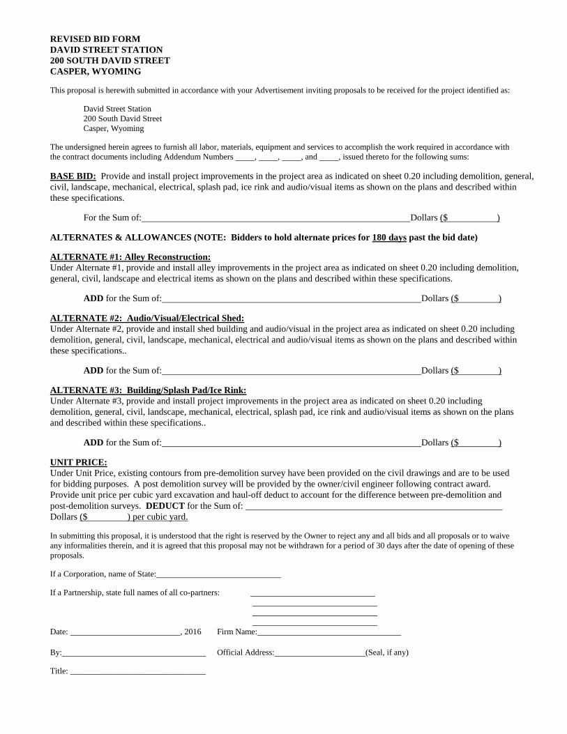
REVISED BID FORM DAVID STREET STATION 200 SOUTH DAVID STREET CASPER, WYOMING This proposal is herewith submitted in accordance with your Advertisement inviting proposals to be received for the project identified as: David Street Station 200 South David Street Casper, Wyoming The undersigned herein agrees to furnish all labor, materials, equipment and services to accomplish the work required in accordance with the contract documents including Addendum Numbers , , , and , issued thereto for the following sums: BASE BID: Provide and install project improvements in the project area as indicated on sheet 0.20 including demolition, general, civil, landscape, mechanical, electrical, splash pad, ice rink and audio/visual items as shown on the plans and described within these specifications. For the Sum of: Dollars ($ ) ALTERNATES & ALLOWANCES (NOTE: Bidders to hold alternate prices for 180 days past the bid date) ALTERNATE #1: Alley Reconstruction: Under Alternate #1, provide and install alley improvements in the project area as indicated on sheet 0.20 including demolition, general, civil, landscape and electrical items as shown on the plans and described within these specifications. ADD for the Sum of: Dollars ($ ) ALTERNATE #2: Audio/Visual/Electrical Shed: Under Alternate #2, provide and install shed building and audio/visual in the project area as indicated on sheet 0.20 including demolition, general, civil, landscape, mechanical, electrical and audio/visual items as shown on the plans and described within these specifications.. ADD for the Sum of: Dollars ($ ) ALTERNATE #3: Building/Splash Pad/Ice Rink: Under Alternate #3, provide and install project improvements in the project area as indicated on sheet 0.20 including demolition, general, civil, landscape, mechanical, electrical, splash pad, ice rink and audio/visual items as shown on the plans and described within these specifications.. ADD for the Sum of: Dollars ($ ) UNIT PRICE: Under Unit Price, existing contours from pre-demolition survey have been provided on the civil drawings and are to be used for bidding purposes. A post demolition survey will be provided by the owner/civil engineer following contract award. Provide unit price per cubic yard excavation and haul-off deduct to account for the difference between pre-demolition and post-demolition surveys. DEDUCT for the Sum of: Dollars ($ ) per cubic yard. In submitting this proposal, it is understood that the right is reserved by the Owner to reject any and all bids and all proposals or to waive any informalities therein, and it is agreed that this proposal may not be withdrawn for a period of 30 days after the date of opening of these proposals. If a Corporation, name of State: If a Partnership, state full names of all co-partners: Date: , 2016 Firm Name: By: Official Address: (Seal, if any) Title: ________________________________

15-015 David Street Station 101400 - 1
SECTION 101400 – SIGNAGE -Site Signs
PART 1 - GENERAL
1.1 RELATED DOCUMENTS
A. Drawings and general provisions of the Contract, including General and Supplementary Conditions and Division 01 Specification Sections, apply to this Section.
1.2 SUMMARY
A. This Section includes the following:
1. Plaques.
2. Panel signs.
1.3 SUBMITTALS
A. Product Data: For each type of product indicated.
B. Shop Drawings: Show fabrication and installation details for signs.
1. Show sign mounting heights, locations of supplementary supports to be provided by others, and accessories.
2. Provide message list, typestyles, graphic elements and layout for each sign.
C. Samples for Verification: For each of the following products and for the full range of color, texture, and sign material indicated, of sizes indicated:
1. Aluminum: For each form, finish, and color, on 6-inch- long sections of extrusions and squares of sheet at least 4 by 4 inches.
2. Alumalite: Square of sheet at least 4 by 4 inches.
D. Sign Schedule: Use same designations indicated on Drawings.
E. Maintenance Data: For signs to include in maintenance manuals.
F. Warranty: Special warranty specified in this Section.
1.4 PROJECT CONDITIONS
A. Weather Limitations: Proceed with installation only when existing and forecasted weather conditions permit installation of signs in exterior locations to be performed according to manufacturers' written instructions and warranty requirements.
B. Field Measurements: Verify recess openings by field measurements before fabrication and indicate measurements on Shop Drawings.
1.5 COORDINATION
A. Coordinate placement of anchorage devices with templates for installing signs.
1.6 WARRANTY
A. Special Warranty: Manufacturer's standard form in which manufacturer agrees to repair or replace components of signs that fail in materials or workmanship within specified warranty period.
1. Failures include, but are not limited to, the following:
15-015 David Street Station 101400 - 2
a. Deterioration of metal and polymer finishes beyond normal weathering.
b. Deterioration of embedded graphic image colors and sign lamination.
2. Warranty Period: Five years from date of Substantial Completion.
PART 2 - PRODUCTS
2.1 MATERIALS
A. Aluminum Sheet and Plate: ASTM B 209, alloy and temper recommended by aluminum producer and finisher for type of use and finish indicated, and with at least the strength and durability properties of Alloy 5005-H32.
B. Applied Vinyl: Die-cut characters from vinyl film of nominal thickness of 3 mils with pressure-sensitive adhesive backing, suitable for exterior applications.
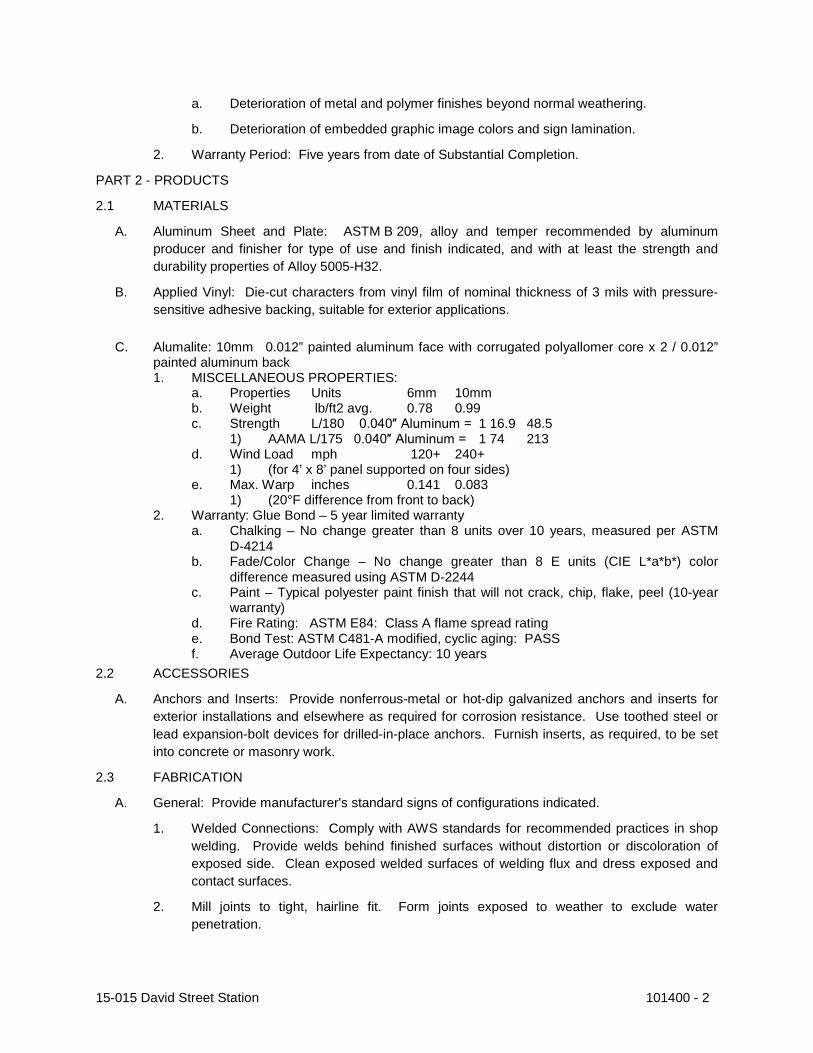
C. Alumalite: 10mm 0.012” painted aluminum face with corrugated polyallomer core x 2 / 0.012” painted aluminum back 1. MISCELLANEOUS PROPERTIES:
a. Properties Units 6mm 10mm b. Weight lb/ft2 avg. 0.78 0.99 c. Strength L/180 0.040″ Aluminum = 1 16.9 48.5
1) AAMA L/175 0.040″ Aluminum = 1 74 213 d. Wind Load mph 120+ 240+
1) (for 4’ x 8’ panel supported on four sides) e. Max. Warp inches 0.141 0.083
1) (20°F difference from front to back) 2. Warranty: Glue Bond – 5 year limited warranty
a. Chalking – No change greater than 8 units over 10 years, measured per ASTM D‐4214
b. Fade/Color Change – No change greater than 8 E units (CIE L*a*b*) color difference measured using ASTM D‐2244
c. Paint – Typical polyester paint finish that will not crack, chip, flake, peel (10-year warranty)
d. Fire Rating: ASTM E84: Class A flame spread rating e. Bond Test: ASTM C481‐A modified, cyclic aging: PASS f. Average Outdoor Life Expectancy: 10 years
2.2 ACCESSORIES
A. Anchors and Inserts: Provide nonferrous-metal or hot-dip galvanized anchors and inserts for exterior installations and elsewhere as required for corrosion resistance. Use toothed steel or lead expansion-bolt devices for drilled-in-place anchors. Furnish inserts, as required, to be set into concrete or masonry work.
2.3 FABRICATION
A. General: Provide manufacturer's standard signs of configurations indicated.
1. Welded Connections: Comply with AWS standards for recommended practices in shop welding. Provide welds behind finished surfaces without distortion or discoloration of exposed side. Clean exposed welded surfaces of welding flux and dress exposed and contact surfaces.
2. Mill joints to tight, hairline fit. Form joints exposed to weather to exclude water penetration.

15-015 David Street Station 101400 - 3
3. Preassemble signs in the shop to greatest extent possible. Disassemble signs only as necessary for shipping and handling limitations. Clearly mark units for reassembly and installation, in location not exposed to view after final assembly.
4. Conceal fasteners if possible; otherwise, locate fasteners where they will be inconspicuous.
2.4 FINISHES, GENERAL
A. Comply with NAAMM's "Metal Finishes Manual for Architectural and Metal Products" for recommendations for applying and designating finishes.
B. Protect mechanical finishes on exposed surfaces from damage by applying a strippable, temporary protective covering before shipping.
C. Appearance of Finished Work: Variations in appearance of abutting or adjacent pieces are acceptable if they are within one-half of the range of approved Samples. Noticeable variations in the same piece are not acceptable. Variations in appearance of other components are acceptable if they are within the range of approved Samples and are assembled or installed to minimize contrast.
2.5 ALUMINUM FINISHES
A. Clear Anodic Finish: Manufacturer's standard Class 1 clear anodic coating, 0.018 mm or thicker, over a polished (buffed) nonspecular as fabricated mechanical finish, complying with AAMA 611.
2.6 STEEL FINISHES
A. Surface Preparation: Remove mill scale and rust, if present, from uncoated steel, complying with SSPC-SP 5/NACE No. 1, "White Metal Blast Cleaning," or SSPC-SP 8, "Pickling."
B. Factory Priming for Painted Finish: Apply shop primer specified below immediately after surface preparation and pretreatment.
1. Shop Primer: Manufacturer's or fabricator's standard, fast-curing, lead- and chromate-free, universal primer, selected for resistance to normal atmospheric corrosion, for compatibility with substrate and field-applied finish paint system indicated, and for capability to provide a sound foundation for field-applied topcoats despite prolonged exposure.
C. Baked-Enamel Finish: Immediately after cleaning and pretreating, apply manufacturer's standard two-coat, baked-enamel finish consisting of prime coat and thermosetting topcoat. Comply with paint manufacturer's written instructions for applying and baking to achieve a minimum dry film thickness of 2 mils.
2.7 STAINLESS-STEEL FINISHES
A. Remove tool and die marks and stretch lines or blend into finish. Grind and polish surfaces to produce uniform, directionally textured, polished finish indicated, free of cross scratches. Run grain with long dimension of each piece.
B. Directional Satin Finish: No. 4 finish.
C. Mirrorlike Reflective, Nondirectional Polish: No. 8 finish.
D. When polishing is completed, passivate and rinse surfaces. Remove embedded foreign matter and leave surfaces chemically clean.

15-015 David Street Station 101400 - 4
PART 3 - EXECUTION
3.1 EXAMINATION
A. Examine substrates, areas, and conditions, with Installer present, for compliance with requirements for installation tolerances and other conditions affecting performance of work.
B. Proceed with installation only after unsatisfactory conditions have been corrected.
3.2 INSTALLATION
A. Locate signs and accessories where indicated, using mounting methods of types described and complying with manufacturer's written instructions.
1. Install signs level, plumb, and at heights indicated, with sign surfaces free of distortion and other defects in appearance.
2. Interior Wall Signs: Install signs on walls adjacent to latch side of door where applicable. Where not indicated or possible, such as double doors, install signs on nearest adjacent walls. Locate to allow approach within 3 inches of sign without encountering protruding objects or standing within swing of door.
B. Wall-Mounted Signs: Comply with sign manufacturer's written instructions except where more stringent requirements apply.
1. Mechanical Fasteners: Use nonremovable mechanical fasteners placed through predrilled holes. Attach signs with fasteners and anchors suitable for secure attachment to substrate as recommended in writing by sign manufacturer.
C. Bracket-Mounted Signs: Provide manufacturer's standard brackets, fittings, and hardware for mounting signs that project at right angles from walls and ceilings. Attach brackets and fittings securely to walls and ceilings with concealed fasteners and anchoring devices to comply with manufacturer's written instructions.
3.3 CLEANING AND PROTECTION
A. After installation, clean soiled sign surfaces according to manufacturer's written instructions. Protect signs from damage until acceptance by Owner.
END OF SECTION 101400