adaptive neural network based control of a hybrid ac/dc
TRANSCRIPT

1
Abstract — In this paper, the behavior of a grid-connected hybrid
AC/DC Microgrid has been investigated. Different Renewable
Energy Sources – photovoltaics modules and a wind turbine
generator - have been considered together with a Solid Oxide
Fuel Cell and a Battery Energy Storage System. The main
contribute of this work is the design and the validation of an
innovative online-trained artificial neural network based control
system for a hybrid microgrid. Adaptive Neural Networks are
used to track the Maximum Power Point of renewable energy
generators and to control the power exchanged between the
Front-End Converter and the electrical grid. Moreover, a fuzzy
logic based Power Management System is proposed in order to
minimize the energy purchased from the electrical grid. The
operation of the hybrid microgrid has been tested in the
Matlab/Simulink environment under different operating
conditions. The obtained results demonstrate the effectiveness,
the high robustness and the self-adaptation ability of the
proposed control system.
Index Terms — Adaptive interaction, fuel cells, microgrid,
neural networks, photovoltaics, predictive control, wind energy,
battery energy storage system.
NOMENCLATURE
AC Alternate Current
ADALINE ADAptive LInear NEuron
AI Adaptive Interaction
BESS Battery Energy Storage System
BP Back-Propagation
CL Context Layer
CPL Constant Power Load
DC Direct Current
DPC Direct Power Control
DPCM Deadbeat Predictive Control Method
ENN Elman Neural Network
FEC Front-End Converter
FFNN Feed Forward Neural Network
FL Fuzzy Logic
HL Hidden Layer
IncCond Incremental Conductance
IL Input Layer
LMS Least Mean Squares
MG Micro-Grid
MPP Maximum Power Point
MPPT Maximum Power Point Tracking
NN Neural Network
OL Output Layer
PI Proportional Integral
PMS Power Management System
PMSG Permanent Magnetic Synchronous Generator
PV Photovoltaic
RBFN Radial Basis Function Network
RES Renewable Energy Sources
SOFC Solid Oxide Fuel Cell
SN-RBFN Single Neuron Radial Basis Function Network
SMC Sliding Mode Control
SOC State Of Charge
SVM Space Vector Modulator
TS-AF Tangent-Sigmoid Activation Function
VF Virtual Flux
WT Wind Turbine
WEGS Wind Energy Generation System
I. INTRODUCTION
OWADAYS, the wide diffusion of distributed RES presents
a new scenario for the regulation of distribution networks
and the availability of new technologies for storage systems
encourages their use in power systems [1]. In general, a hybrid
AC/DC MG integrates different Distributed Generators (e.g.
solar power sources, wind power generators, cogenerators,
etc.), a energy storage system and a number of AC and DC
loads. A FEC can interface the MG with the electric grid and
can operate either in a grid-connected or islanded mode. The
use of a PMS is crucial to optimize the power flow through the
different components of the MG and the exchange of energy
with the electric grid. Moreover, since the power produced by
RESs depends on the climatic conditions, MPPT algorithms
are needed in order to harvest the maximum available energy.
The intermittent nature of RESs with the time-varying loads
demand make the use of advanced control structures
fundamental in order to make the operation of the MG
reliable, economic, and secure under different operating
conditions. The MG must also guarantee a high quality power
supply to both local loads and electrical grid.
Many works have focused on hybrid microgrids and have
proposed a number of control schemes for different mode of
operations [2]-[8]. A multiagent-based energy management
system to optimizes the economic operation of a MG is
presented in [2]. A reactive power sharing algorithm in
hierarchical droop control is developed in [3]. A novel
coordinated voltage control scheme with islanding capability
for a MG is proposed in [4]. For highly nonlinear and complex
AC/DC MGs, control schemes based on artificial intelligence
techniques such as Fuzzy Logic (FL), Neural Network (NN),
and evolutionary algorithms are gaining widespread interest.
Intelligent controllers are very promising because they can
Adaptive Neural Network-Based Control of a
Hybrid AC/DC Microgrid
N. Chettibi , A. Mellit, G. Sulligoi, IEEE Senior Member, and A. Massi Pavan, IEEE Member
N

2
adapt to uncertainties and they can be used also when the
model of the system to be controlled is not available.
Recently, the NNs with the learning capability are widely
applied for the control of complex power systems. In [9], a
back-propagation NN is applied for the real-time estimation of
the wind speed. A novel discrete-time NN controller for the
control of DC distribution system is designed in [10]. In [11],
a RBFN and an improved ENN are proposed as MPPT
controllers for different types of RES. A RBFN with an ENN
have been also analyzed in [12] for the wind speed prediction
in a wind farm.
The different NNs based techniques proposed in the
literature can be classified, according to the training algorithm,
into two categories [13]: offline and online trained NN.
Offline learning of a neuro-controller is usually accomplished using a training dataset coming from the system model or
from experimental data. When the controlled system is too
complex to be modeled and/or experimental datasets are not
available, it is more adequate to use online trained NNs that
respond dynamically to the system uncertainties resulting from
nonlinearities, parameters changing and exterior perturbations.
In this paper, a grid-connected hybrid MG which consist of
a PV source, a WT generator, a SOFC, a BESS and two
equivalent DC and AC loads is studied. A PMS based on FL is
proposed to supervise the power flow in the MG. Online-
trained NNs based MPPT for the RESs in addition to
ADALINE based linear controllers for both SOFC stack and
BESS are introduced. Moreover, a simplified deadbeat based
predictive control scheme is applied for the WEGS. Further, a
VF-DPC strategy for the bidirectional FEC is adopted. A
FFNN is proposed for the regulation of the DC-bus voltage.
Two ENNs based controllers are adopted to ensure the control
of the bidirectional flow of the active power as well as the
compensation of the AC load reactive power. An AI based
algorithm is applied for the online weights adaptation of the
proposed FFNN and ENNs. The investigated MG is simulated
in the Matlab/Simulink environment. Then, the effectiveness
of the proposed controllers is verified for different test cases.
The paper is organized as follows: the next Section in on the
configuration and the modeling of the MG, Section III deals
with the control scheme, the simulation results are given in
Section IV, and Section V is on Conclusions and Perspectives.
II. SYSTEM CONFIGURATION AND MODELING
As shown in Fig.1, the investigated MG is connected to the
electric grid though a FEC, while the DC-Bus is fed by four
energy sources: a 21kWp PV generator, a 10kW WEGS, a
10kW SOFC, and a 20Ah Lithium-Ion BESS. A bidirectional
buck-boost converter interfaces the BESS with the DC link.
Whereas, boost converters are used for coupling the PV source
and SOFC with the DC-bus. A filter capacitor Cdc is connected
to the DC-bus to minimise the DC voltage ripples. Moreover,
the MG includes also AC and DC loads. The circuit model of
the converters used in the MG is shown in Fig.2.
Fig. 1. Hybrid Microgrid configuration.
Fig. 2. Circuit model of the considered converters.
A. Modeling the PV generator
The equivalent circuit used to model a PV module is shown
in Fig.3 and is represented by the following equation [14]:
𝐼𝑃𝑉 = 𝑛𝑝𝐼𝑃𝐻 − 𝑛𝑝𝐼𝑆 [𝑒𝑥𝑝 (𝑞
𝐴𝐾𝑇) (
𝑉𝑃𝑉
𝑛𝑠+ 𝐼𝑃𝑉𝑅𝑆) − 1] (1)
Where IPV and VPV are the PV module’s output current and
voltage, RS is the series resistance, IPH is the photocurrent, IS is
the saturation current, q is the electron charge, K is the
Boltzman constant, A is the diode ideality factor, T is the
temperature, while nP and nS are the numbers of series and
parallel-connected solar cells.
Fig. 3. Single diode equivalent circuit of PV module.
B. Modeling the Wind Energy Generation System
The WEGS consists of a WT coupled to a PMSG, where an
AC-DC Rectifier is used for the interfacing with the DC-bus.
The mathematical model of the PMSG implemented in the
synchronous rotating frame dq is given as [15, 16]:
{𝑉𝑠𝑑 = −𝑅𝑠𝐼𝑠𝑑 − 𝐿𝑠𝑑
𝑑𝐼𝑠𝑑
𝑑𝑡+ 𝐿𝑠𝑞𝜔𝑒𝐼𝑠𝑞
𝑉𝑠𝑞 = −𝑅𝑠𝐼𝑠𝑞 − 𝐿𝑠𝑞𝑑𝐼𝑠𝑞
𝑑𝑡− 𝐿𝑠𝑑𝜔𝑒𝐼𝑠𝑑 + 𝜔𝑒𝜙
(2)
Where Vsd, Vsq, Isd and Isq are the d and q-axis components of
the stator voltages and currents; Lsd and Lsd are the d and q-
axis inductance, ωe is the generator speed defined as [15]:
𝜔𝑒 = 𝑝.𝜔𝑡 such that p is the number of pole pairs and ωt is
the angular velocity of WT, ϕ is the permanent magnet flux,
and Rs is the stator resistance. The electromagnetic torque Te
developed by the generator can be written as [16]:

3
𝑇𝑒 =3
2𝑝 ((𝐿𝑠𝑑 − 𝐿𝑠𝑞)𝐼𝑠𝑞𝐼𝑠𝑑 + 𝜙𝐼𝑠𝑞) (3)
Considering that for nonsalient PMSG Lsd = Lsq=Ls, Eq.3
can be rewritten as:
𝑇𝑒 =3
2𝑝𝐼𝑠𝑞𝜙 (4)
Since the magnetic flux is constant, the electromagnetic
torque and the q-axis stator current component Isq are directly
proportional. Whereas, the reactive power may be controlled
depending on the d-axis current component Isd. The motion
equation is given by [15]:
𝐽𝑑𝜔𝑚
𝑑𝑡= 𝑇𝑡 − 𝑇𝑒 − 𝐹𝜔𝑚 (5)
Where F is the viscous friction factor, J is the moment of
inertia. The aerodynamic torque of WT is defined as the ratio
between the aerodynamic power Pt and the WT angular
velocity:
𝑇𝑡 = 𝑃𝑡 𝜔𝑡⁄ = 0.5𝜋𝜌𝑅2𝐶𝑃𝑉𝑊3 𝜔𝑡⁄ (6)
Where ρ, VW, R, CP are the air density, the wind speed, the
radius of turbine blade and the power coefficient, respectively.
C. Modeling the Solid Oxide Fuel Cell
The dynamic model adopted for the SOFC [17,18] is based
on the relationship between the FC output voltage Vfc and the
partial pressures of hydrogen, oxygen, and water PH2, PO2,
PH2O, respectively. The SOFC terminal voltage Vfc is
determined using the Nernst’s equation and Ohm’s law as
[17,18]:
𝑉𝑓𝑐 = 𝑁0 (𝐸0 +𝑅𝑇
2𝐹(𝑙𝑛 (
𝑃𝐻2𝑃𝑂20.5
𝑃𝐻2𝑂))) − 𝑟𝐼𝑓𝑐 (7)
Where N0 is the number of series connected cells, E0 is the
free reaction voltage, R is the universal gas constant, T is the
temperature, F is the Faraday’s constant, Ifc is the FC output
current, and r is the ohmic resistance.
D. Modeling the Battery Energy Storage System
The Matlab/Simulink module used for the BESS simulation
consists of a controlled voltage source series-connected with
an internal resistance [19]. The battery output voltage and the
State Of Charge (SOC) are calculated as follows:
𝑉𝑏 = 𝐸0 − 𝑅𝑖𝑛𝐼𝑏 −𝐾𝑄
𝑄−∫ 𝐼𝑏(𝑡)𝑑𝑡𝑡
0
+ 𝐴𝑒𝑥𝑝 (−𝐵 ∫ 𝐼𝑏𝑑𝑡𝑡
0) (8)
𝑆𝑂𝐶 = 100(1 −∫ 𝐼𝑏𝑑𝑡𝑡
0
𝑄) (9)
Where Vb and Ib are the BESS terminal voltage and current,
E0 is the BESS no-load voltage, Rin is the internal resistance, K
is the polarization voltage, Q is the BESS capacity, A is the
exponential zone amplitude, and B is the inverse exponential
zone time constant. In this paper, a 20 Ah Lithium-Ion battery
bank is used.
III. CONTROL STRUCURE OF THE HYBRID MICROGRID
The main tasks of the control system of a hybrid MG are: to
minimize the amount of power purchased from the electric
grid, to make the RESs based generators operate at their MPPs
and to ensure a high-quality power supply to local loads and to
electric grid. Being motivated by the benefits of learning
ability, robustness against uncertainties and adaptability, a
number of intelligent NN controllers have been designed and
used instead of the conventional controllers, in order to satisfy
the above requirements.
A. MPPT control of PV generator
The PV source exhibits a nonlinear behavior depending
upon the variable operating conditions, and the maximum
output power is generated at an unique operating point.
Several MPPT algorithms heva been proposed in the
litherature to extract the maximum energy from PV modules.
One of them is the well-known incremental conductance
(IncCond) algorithm [20,21]. This method consists in the
regulation of the PV voltage according to the MPP voltage
reference. At each iteration, the PV voltage reference is
adjusted based on the comparison of the incremental
conductance (dI/dV) of the PV source with the negative
instantaneous conductance (-I/V). The position of the
operating point with respect to the MPP on the PV power
curve is known based on the following equation [20]:
{
𝑑𝐼
𝑑𝑉= −
𝐼
𝑉 𝑎𝑡 𝑡ℎ𝑒 𝑀𝑃𝑃
𝑑𝐼
𝑑𝑉> −
𝐼
𝑉 𝑎𝑡 𝑙𝑒𝑓𝑡 𝑜𝑓 𝑡ℎ𝑒 𝑀𝑃𝑃
𝑑𝐼
𝑑𝑉< −
𝐼
𝑉 𝑎𝑡 𝑟𝑖𝑔ℎ𝑡 𝑜𝑓 𝑡ℎ𝑒 𝑀𝑃𝑃
(10)
The IncCond method is simple and easy to implement. But,
the convergence speed and the steady state power oscillations
depend mainly on the size of the step change in the reference
voltage. In this paper, a SN-RBFN based controller is applied
to overcome the nonlinear issues arising with such MPPTs.
The aim is to enhance the dynamic performance and the
tracking accuracy of the IncCond algorithm. The MPP of the
studied PV generator is tracked through a DC-DC boost
converter. As shown in Fig.4a, a PI voltage controller
generates the gate signal of the power switch, while the SN-
RBFN based controller generates the PV voltage reference.
The proposed MPPT regulator is based on the principle of the
IncCond technique. The learning ability of the SN-RBFN
tracker ensures the self-adaptation to any change of operating
conditions.The adopted SN-RBFN contains a single hidden
node that uses the Gaussian function defined as [22]:
𝑓(𝑥) = 𝑒𝑥𝑝 (−‖𝑥−𝑐‖2
2𝑏2) = ℎ (11)
Where c is the central point of the Gaussian function f(x), b
is the width value of f(x), and x=[x1,x2,x3] is the input vector
and ‖ ‖ denotes the Euclidean norm. The SN-RBFN output
(y) is calculated as: 𝑦 = 𝑉𝑝𝑣𝑟𝑒𝑓 = 𝑎0 + 𝑎1𝑓(𝑥) (12)
Where a0 and a1 are the bias and the weight of the SN-RBFN
respectively, and Vpvref is the PV voltage reference at the
output of MPPT controller. The SN-RBFN’s inputs are: the
instantaneous conductance (I/V), the incremental conductance
(ΔI/ΔV), and the reference voltage error (ΔVpvref(k)=Vpvref(k)-
Vpvref(k-1)). In this paper, a supervised learning rule based
gradient descent method [11,23] is adopted for the online
update of the SN-RBFN parameters. The objective function
used for the weights adaptation is defined as:
𝜎(𝑘) = 𝑒𝑦(𝑘)2 2⁄ = (𝑦𝑑 − 𝑦)
2 2⁄ (13)
Where ey is the output error, and yd is the desired output
voltage. The goal of the online learning process of the SN-
4
RBFN is to minimize the performance index function σ(k).
Thus, the adaptation laws of the SN-RBFN gains are given
according to the gradient descent method as follows:
𝑎𝑖(𝑘 + 1) = 𝑎𝑖(𝑘) + ∆𝑎𝑖(𝑘) + 𝛼(𝑎𝑖(𝑘) − 𝑎𝑖(𝑘 − 1)) (14)
𝑐𝑗1(𝑘 + 1) = 𝑐𝑗1(𝑘) + ∆𝑐𝑗1(𝑘) + 𝛼 (𝑐𝑗1(𝑘) − 𝑐𝑗1(𝑘 − 1)) (15)
𝑏(𝑘 + 1) = 𝑏(𝑘) + ∆𝑏(𝑘) + 𝛼(𝑏(𝑘) − 𝑏(𝑘 − 1)) (16)
Where α is the momentum factor, k is the k-th iteration,
i=0,1, and j=1,2,3. According to the BP algorithm based on
the gradient descent rule, the SN-RBFN parameters ai, cj1 and
b are adjusted by computing the gradient of the error function
σ(k) with respect to the SN-RBFN coefficients, so that σ(k) is
eliminated. The derivative of the error function σ(k) against
each SN-RBFN’s gain is evaluated by propagating the error
term back through the NN. Thus, the SN-RBFN parameters
are adjusted using the formulas :
∆𝑎0(𝑘) = −𝜇𝜕𝜎
𝜕𝑎0= −𝜇
𝜕𝜎
𝜕𝑦
𝜕𝑦
𝜕𝑎0= 𝜇𝑒𝑦(𝑘) (17)
∆𝑎1(𝑘) = −𝜇𝜕𝜎
𝜕𝑎1= −𝜇
𝜕𝜎
𝜕𝑦
𝜕𝑦
𝜕𝑎1= 𝜇𝑒𝑦(𝑘)𝑓(𝑥) (18)
∆𝑐𝑗1(𝑘) = −𝜇𝜕𝜎
𝜕𝑐𝑗1= −𝜇
𝜕𝜎
𝜕𝑦
𝜕𝑦
𝜕ℎ
𝜕ℎ
𝜕𝑐𝑗1= 𝜇𝑎1𝑒𝑦(𝑘)(𝑥𝑗 − 𝑐𝑗1) 𝑓(𝑥) 𝑏
2⁄
(19)
∆𝑏(𝑘) = −𝜇𝜕𝜎
𝜕𝑏= −𝜇
𝜕𝜎
𝜕𝑦
𝜕𝑦
𝜕ℎ
𝜕ℎ
𝜕𝑏= 𝜇𝑎1𝑒𝑦(𝑘)‖𝑥 − 𝑐‖
2 𝑓(𝑥) 𝑏3⁄
(20)
Where μ denotes the learning rate. We define the variable
Gin(k)= (I(k)/V(k))+(ΔI(k)/ΔV(k)) that has to be equal to zero
at the MPP. Since the desired output of SN-RBFN based
MPPT controller (yd) is unknown, the error eG(k)=(0 - Gin(k))
is used instead of ey(k) in Eq.17-20. Thus, the iterative
learning algorithm of the SN-RBFN based MPPT controller is
given as:
{
𝑎0(𝑘 + 1) = 𝑎0(𝑘) + 𝜇𝐺𝑖𝑛(𝑘) + 𝛼(𝑎0(𝑘) − 𝑎0(𝑘 − 1))
𝑎1(𝑘 + 1) = 𝑎1(𝑘) + 𝜇𝐺𝑖𝑛(𝑘)𝑓(𝑥) + 𝛼(𝑎1(𝑘) − 𝑎1(𝑘 − 1))
𝑐𝑗1(𝑘 + 1) = 𝑐𝑗1(𝑘) + 𝜇𝑎1𝐺𝑖𝑛(𝑘)(𝑥𝑗 − 𝑐𝑗1)𝑓(𝑥) 𝑏2⁄ + 𝛼 (𝑐𝑗1(𝑘) − 𝑐𝑗1(𝑘 − 1))
𝑏(𝑘 + 1) = 𝑏(𝑘) + 𝜇𝑎1𝐺𝑖𝑛(𝑘)‖𝑥 − 𝑐‖2 𝑓(𝑥) 𝑏3⁄ + 𝛼(𝑏(𝑘) − 𝑏(𝑘 − 1))
(21)
Once the term Gin(k) converges to zero, the SN-RBFN
stabilizes at the reached operating power point that correspond
to the MPP of PV source at the given climatic condition.
B. Predictive torque control for the PMSG
The block diagram of the control scheme of the AC-DC
converter used for the PMSG is depicted in Fig.4.b. A DPCM
based on the Deadbeat approach [24-26] is applied to drive
the AC-DC rectifier in order to improve the dynamic
performance of the classical direct torque control scheme of
PMSG. Besides, an ADALINE based MPPT controller is
proposed for the tight regulation of the rotating speed of WT.
The main tasks of the PMSG control system are to
instantaneously follow the MPP of WT generator, to track the
electromagnetic torque reference, and to maintain the direct
stator current component close to zero.
The basic idea of the adopted DPCM is to compute, at each
sampling period, and apply the optimal stator voltage vector
that ensures the minimization, at the next sampling instant, of
the tracking errors between the predicted and the reference
values of the controlled variables [24,25]. Using the calculated
voltage vector, the proper switching pulses for rectifier are
generated through the Space-Vector Modulator (SVM).
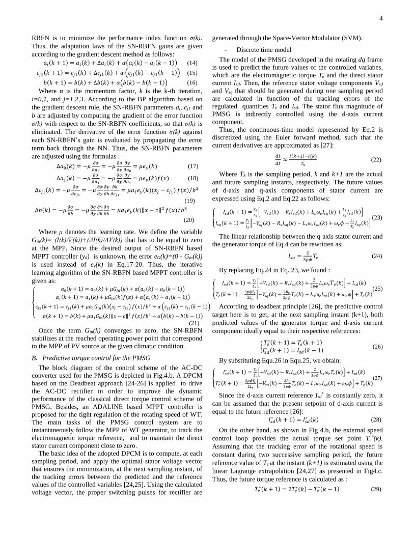
- Discrete time model
The model of the PMSG developed in the rotating dq frame
is used to predict the future values of the controlled variabes,
which are the electromagnetic torque Te and the direct stator
current Isd. Then, the reference stator voltage components Vsd
and Vsq that should be generated during one sampling period
are calculated in function of the tracking errors of the
regulated quantities Te and Isd. The stator flux magnitude of
PMSG is indirectly controlled using the d-axis current
component.
Thus, the continuous-time model represented by Eq.2 is
discretized using the Euler forward method, such that the
current derivatives are approximated as [27]:
𝑑𝐼
𝑑𝑡≈
𝐼(𝑘+1)−𝐼(𝑘)
𝑇𝑠 (22)
Where TS is the sampling period, k and k+1 are the actual
and future sampling instants, respectively. The future values
of d-axis and q-axis components of stator current are
expressed using Eq.2 and Eq.22 as follows:
{𝐼𝑠𝑑(𝑘 + 1) =
𝑇𝑠
𝐿𝑠[−𝑉𝑠𝑑(𝑘) − 𝑅𝑠𝐼𝑠𝑑(𝑘) + 𝐿𝑠𝜔𝑒𝐼𝑠𝑞(𝑘) +
𝐿𝑠
𝑇𝑠𝐼𝑠𝑑(𝑘)]
𝐼𝑠𝑞(𝑘 + 1) =𝑇𝑠
𝐿𝑠[−𝑉𝑠𝑞(𝑘) − 𝑅𝑠𝐼𝑠𝑞(𝑘) − 𝐿𝑠𝜔𝑒𝐼𝑠𝑑(𝑘) + 𝜔𝑒𝜙 +
𝐿𝑠
𝑇𝑠𝐼𝑠𝑞(𝑘)]
(23)
The linear relationship between the q-axis stator current and
the generator torque of Eq.4 can be rewritten as:
𝐼𝑠𝑞 =2
3𝑝𝜙𝑇𝑒 (24)
By replacing Eq.24 in Eq. 23, we found :
{𝐼𝑠𝑑(𝑘 + 1) =
𝑇𝑠
𝐿𝑠[−𝑉𝑠𝑑(𝑘) − 𝑅𝑠𝐼𝑠𝑑(𝑘) +
2
3𝑝𝜙𝐿𝑠𝜔𝑒𝑇𝑒(𝑘)] + 𝐼𝑠𝑑(𝑘)
𝑇𝑒(𝑘 + 1) =3𝑝𝜙𝑇𝑠
2𝐿𝑠[−𝑉𝑠𝑞(𝑘) −
2𝑅𝑠
3𝑝𝜙𝑇𝑒(𝑘) − 𝐿𝑠𝜔𝑒𝐼𝑠𝑑(𝑘) + 𝜔𝑒𝜙] + 𝑇𝑒(𝑘)
(25)
According to deadbeat principle [26], the predictive control
target here is to get, at the next sampling instant (k+1), both
predicted values of the generator torque and d-axis current
component ideally equal to their respective references:
{𝑇𝑒∗(𝑘 + 1) = 𝑇𝑒(𝑘 + 1)
𝐼𝑠𝑑∗ (𝑘 + 1) = 𝐼𝑠𝑑(𝑘 + 1)
(26)
By substituting Equ.26 in Equ.25, we obtain:
{𝐼𝑠𝑑∗ (𝑘 + 1) =
𝑇𝑠
𝐿𝑠[−𝑉𝑠𝑑(𝑘) − 𝑅𝑠𝐼𝑠𝑑(𝑘) +
2
3𝑝𝜙𝐿𝑠𝜔𝑒𝑇𝑒(𝑘)] + 𝐼𝑠𝑑(𝑘)
𝑇𝑒∗(𝑘 + 1) =
3𝑝𝜙𝑇𝑠
2𝐿𝑠[−𝑉𝑠𝑞(𝑘) −
2𝑅𝑠
3𝑝𝜙𝑇𝑒(𝑘) − 𝐿𝑠𝜔𝑒𝐼𝑠𝑑(𝑘) + 𝜔𝑒𝜙] + 𝑇𝑒(𝑘)
(27)
Since the d-axis current reference Isd* is constantly zero, it
can be assumed that the present setpoint of d-axis current is
equal to the future reference [26]:
𝐼𝑠𝑑∗ (𝑘 + 1) = 𝐼𝑠𝑑
∗ (𝑘) (28)
On the other hand, as shown in Fig 4.b, the external speed
control loop provides the actual torque set point Te*(k).
Assuming that the tracking error of the rotational speed is
constant during two successive sampling period, the future
reference value of Te at the instant (k+1) is estimated using the
linear Lagrange extrapolation [24,27] as presented in Fig4.c.
Thus, the future torque reference is calculated as :
𝑇𝑒∗(𝑘 + 1) = 2𝑇𝑒
∗(𝑘) − 𝑇𝑒∗(𝑘 − 1) (29)

5
Substituting Eq.29 and Eq.28 in Eq.27, the d-axis and q-axis
components of the required stator voltage vector are given as:
{𝑉𝑠𝑑(𝑘) = −𝑅𝑠𝐼𝑠𝑑(𝑘) +
2
3𝑝𝜙𝐿𝑠𝜔𝑒𝑇𝑒(𝑘) −
𝐿𝑠
𝑇𝑠∆𝐼𝑠𝑑(𝑘)
𝑉𝑠𝑞(𝑘) = −2𝑅𝑠
3𝑝𝜙𝑇𝑒(𝑘) − 𝐿𝑠𝜔𝑒𝐼𝑠𝑑(𝑘) + 𝜔𝑒𝜙 −
2 𝐿𝑠
3𝑝𝜙𝑇𝑠(∆𝑇𝑒(𝑘) + 𝑑𝑇𝑒
∗(𝑘))(30)
Where ΔTe(k) and ΔIsd(k) are the instantaneous tracking
errors of the torque and the d-axis current, respectively. While,
dTe*(k) is the current variation in the torque reference:
{
∆𝐼𝑠𝑑(𝑘) = 𝐼𝑠𝑑∗ (𝑘) − 𝐼𝑠𝑑(𝑘)
∆𝑇𝑒(𝑘) = 𝑇𝑒∗(𝑘) − 𝑇𝑒(𝑘)
𝑑𝑇𝑒∗(𝑘) = 𝑇𝑒
∗(𝑘) − 𝑇𝑒∗(𝑘 − 1)
(31)
- ADALINE based speed controller
Traditionally, a Proportional Integral (PI) controller is used
to regulate the rotating speed of WT in order to extract the
maximum wind energy. However, a PI controller with fixed
gains for a time-varying WEGS, which is subject to random
wind speed and parameters variations, can yield to poor
dynamic performance. To overcome this drawback, an
adaptive ADALINE (ADaptive LInear NEuron) network
based controller is adopted in this paper, to control the
rotational speed by producing the reference for the
electromagnetic torque. The ADALINE based speed controller
consists of a single neuron with linear activation function,
where the output is calculated as [13, 28]:
𝑦𝑤(𝑘) = 𝑇𝑒∗(𝑘) = ∑ 𝑥𝑖(𝑘)𝑤𝑖(𝑘)
𝑛=3𝑖=1 = 𝑋𝜔
𝑇 .𝑊𝜔 (32)
Where wi is the ith weight coefficient (i=1,2,3), xi is the ith
input signal and n is the number of inputs. Xω and Wω are the
inputs and weights vectors, respectively. The ADALINE
output is the electromagnetic torque reference Te*(k), while the
inputs are the measured speed at the instant k ωe(k), the actual
speed error eω(k)=ωe*(k)-ωe(k), and the previous error eω(k-1).
Such that ωe*(k) is the speed reference. The Widrow–Hoff
Least Mean Square (LMS) learning algorithm [28] is used for
the online update of the ADALINE’s weights. Where, the goal
of the self-learning process of the ADALINE based speed
controller is to minimize the mean square of the instantaneous
error eω(k). Using the transformation 𝑋′ = 0.5 𝑠𝑔𝑛(𝑋𝜔) +0.5𝑋𝜔 [28], the weight vector is adjusted as:
𝑊𝜔(𝑘 + 1) = 𝑊𝜔(𝑘) + 𝛼𝜔𝑒𝜔(𝑘)𝑋
′
𝜆+‖𝑋′‖2 (33)
Where Wω(k+1) and Wω(k) are the weight vectors at the next
and present iteration, k+1 and k, respectively. 𝜆 is a correction
factor, αω is the learning rate, and ‖𝑋′‖2 is the squared norm of
the input vector 𝑋′. The learning coefficient αω which has a
value in the interval [0.1,1] affect considerably the speed of
convergence to the optimal weighting factors of the
ADALINE network. The continuous adjustment of the
ADALINE’s weights using the normalized LMS law of
Equ.33, ensures the self-adaptation of the adopted speed
controller to any change of working conditions unlike the PI
regulator with fixed gains .
C. Control of the SOFC stack
As depicted in Fig.4.d, an ADALINE based power
controller with two adaptive weights regulates the SOFC’s
output power to follow the power reference provided by the
central power supervisor. The inputs of the ADALINE
controller are the power error (efc(k) =Pfc (k)-P*
fc(k)), and the
change of error (defc(k)=efc(k)-efc(k-1)). Such that, Pfc*(k) and
Pfc(k) are the power reference and the output power generated
by the SOFC stack, respectively. Whereas, the output is the
duty cycle Dfc(k) that controls the commutation time of the
switching device of the boost converter. The control error
Efc(k) used for the online learning process of the SOFC’s
power controller is defined in function of the sliding surface
Sfc(k) as:
𝐸𝑓𝑐(𝑘) = 0−𝑆𝑓𝑐(𝑘) = −[𝜆1. 𝑒𝑓𝑐(𝑘) + 𝑑𝑒𝑓𝑐(𝑘)] (34)
Where 𝜆1 is a positive constant. According to the SMC
principle [29], the control goal here is to maintain the
trajectory of the state variable, which is the SOFC’s output
power, on the sliding surface Sfc(k)=0 for the whole time. With
reference to the LMS algorithm [13], the weight vector (Wfc)
of the SOFC’s controller is updated at each iteration of the
online training process as follows:
𝑊𝑓𝑐(𝑘 + 1) = 𝑊𝑓𝑐(𝑘) + 2𝛼2 𝐸𝑓𝑐(𝑘)𝑋𝑓𝑐(𝑘) (35)
Where Xfc is the input vector and α2 is the learning rate of the
SOFC’s controller. In this case, the connective weights are
adapted in such way that the sliding surface Sfc(k) tend to zero,
so that the power tracking error will be eliminated.
Fig. 4. a) SNRBN based PV controller, b) control scheme of WEGS,
c) Estimation of future value of torque [24], d) SOFC’s controller,
and e) BESS’s controller.

6
D. Control of the BESS
The control of the charge and discharge of BESS is
performed through a bidirectional DC-DC converter. As
shown in Fig.4.e, the BESS power reference P*b, provided by
the PMS, is divided by the BESS terminal voltage to generate
the current set point I*b. Then, an ADALINE based controller
is used to regulate the BESS’s output current Ib to follow its
setpoint I*b. The inputs of the BESS’s ADALINE regulator are
the actual BESS current error eb(k) and the past current error
eb(k-1). Whereas, the output is the duty cycle Db(k) of the
PWM control signal of the buck-boost converter. Such that,
the present current error eb(k) is defined as the difference
between the current reference I*b(k) and the measured BESS
current Ib(k). The control objective used for the adaptation of
the gains is expressed in term of the sliding surface Sb(k) as:
𝐸𝑏(𝑘) = 0 − 𝑆𝑏(𝑘) = −[𝜆2. 𝑒𝑏(𝑘) + 𝑑𝑒𝑏(𝑘)] (36)
Where Eb(k) is the error term used for the weights update,
𝑑𝑒𝑏(𝑘) = 𝑒𝑏(𝑘) − 𝑒𝑏(𝑘 − 1) is the change of the BESS current
error, and 𝜆2 is a positive constant. Where, the ADALINE’s
weights vector Wb are online adjusted via a LMS-rule as
follows:
𝑊𝑏(𝑘 + 1) = 𝑊𝑏(𝑘) + 2𝛼3 𝐸𝑏(𝑘)𝑋𝑏(𝑘) (37)
Where Xb and α3 are, respectively, the input vector and the
learning rate of the BESS’s controller. If the sliding function
Sb(k) in the steady state, is close to zero, that means that the
trajectory of the BESS’s current Ib is forced to stay on it.
E. Control of the FEC
A Virtual Flux based Direct Power Control [30] scheme is
applied for the control of the FEC. Assuming that the grid
voltage vector 𝑢𝑔 and the inductance filter L are virtual AC
motor quantities, the grid VF voltage Ψ𝑔is defined as:
Ψ𝑔 = ∫𝑢𝑔𝑑𝑡 = ∫𝑢𝑐 − 𝑅𝑖𝑐 − 𝐿𝑑𝑖𝑐
𝑑𝑡 𝑑𝑡 (38)
𝑢𝑐 is the inverter voltage vector and 𝑖𝑐is the FEC output
current vector. The voltage drop across the filter resistance R
is neglected. In the stationary αβ frame, the αβ components of
the grid VF are calculated in term of the inverter switching
states (Sa,Sb,Sc), the αβ current components (icα,icβ) and the
measured DC-link voltage VDC:
{Ψ𝑔𝛼 = ∫
𝑉𝐷𝐶
3(2𝑆𝑎 − 𝑆𝑏 − 𝑆𝑐)𝑑𝑡 − 𝐿 𝑖𝑐𝛼
Ψ𝑔𝛽 = ∫𝑉𝐷𝐶
√3(𝑆𝑏 − 𝑆𝑐)𝑑𝑡 − 𝐿 𝑖𝑐𝛽
(39)
Based on the grid VF components Ψgα,β, the instantaneous
active and reactive power (P,Q) can be estimated as [30]:
{𝑃 =
3
2𝜔 ∙ (Ψ𝑔𝛼𝑖𝑐𝛽 −Ψ𝑔𝛽𝑖𝑐𝛼)
𝑄 =3
2𝜔 ∙ (Ψ𝑔𝛼𝑖𝑐𝛼 +Ψ𝑔𝛽𝑖𝑐𝛽)
(40)
In a conventional DPC scheme, PI controllers are used to
control the DC-bus voltage as well as the active and reactive
power flows. However, the irregular RESs power generation
and the time-varying load demand require that the FEC works
dynamically over a wide range of MG operation. For this
purpose, NN based controllers are used in the adopted VF-
DPC scheme instead of the linear PI controllers in order to
improve the dynamic performance and to react adaptively to
the varying conditions. As depicted in Fig.5, a FFNN is
employed for the outer DC voltage control loop, while ENNs
based controllers are applied for the power control loops. The
Adaptive Interaction algorithm proposed by Brandt and Lin
[31] is used for the online weights adaptation of the proposed
FFNN and ENN controllers.
Fig. 5. VF-DPC scheme of the FEC.
Fig. 6. a) Architecture of the ENN based power controller, b) a
exemple of the simulink block used for FFNN weights adaptation
with AI rule.
- The principle of the AI algorithm for NN training
The adjustment of the NN weights with the adaptive
interaction algorithm is equivalent but simpler than the well-
known BP approach. Moreover, it does not need to back
propagate the output error through the network [31]. The most
prominent features of the AI approach are the adaptation
during the interaction of neurons and the low computational
requirements in comparison to the BP algorithm. In this
subsection, the NN weights adaptation law based on the AI
algorithm is given. The output of each node in the l-th layer of
a NN is calculated as:
𝑥𝑛(𝑙)= 𝑓𝑛
(𝑙)(𝑛𝑒𝑡𝑛
(𝑙)) = 𝑓𝑛
(𝑙)(∑ 𝑤𝑖𝑥𝑖
(𝑙−1)𝑁𝑖=1 ) (41)
Where xn(l)
and fn(l) are the output and the activation function of
the n-th node in the l-th layer respectively, xi(l-1) is i-th input of
n-th node, wi is the connection weight from i-th input to the n-
th node, and N is the number of inputs to the l-th layer. The
training process aims to minimize the cost function E
expressed as [13]:
𝐸 =1
2∑ 𝑒𝑛
2𝑚𝑛=1 (42)

7
Where 𝑒𝑛 = {𝑥𝑛(𝑙)− 𝑑𝑛 𝑓𝑜𝑟 𝑜𝑢𝑡𝑝𝑢𝑡 𝑛𝑜𝑑𝑒
0 𝑜𝑡ℎ𝑒𝑟𝑤𝑖𝑠𝑒 (43)
m is the number of the output neurons. dn is the desired
output of the n-th output neuron. The weights of the NN can be
dynamically updated according to the AI law [13,31] as
follows:
∆𝑤𝑖 = 𝑓𝑛(𝑙)′(𝑛𝑒𝑡𝑛
(𝑙))𝑥𝑖(𝑙−1)
𝑥𝑛(𝑙)∑ 𝑤𝑜𝑗∆𝑃𝑗=1 𝑤𝑜𝑗 − 𝛾𝑓𝑛
(𝑙)′(𝑛𝑒𝑡𝑛
(𝑙))𝑥𝑖
(𝑙−1)𝑒𝑛 (44)
Where γ>0 is the adaptation coefficient and P is the number
neurons in the next layer. woj is the weight connecting o-th with
j-th neuron. The Tangent-Sigmoid Activation Function (TS-
AF) of neurons is defined as:
𝑥𝑛(𝑙)= 𝑓𝑛
(𝑙)(𝑛𝑒𝑡𝑛
(𝑙)) =
2
1+𝑒−𝑛𝑒𝑡𝑛(𝑙) − 1 =
1−𝑒−𝑛𝑒𝑡𝑛(𝑙)
1+𝑒−𝑛𝑒𝑡𝑛(𝑙) (45)
The time derivative of TS-AF is so calculated as:
𝑓𝑛(𝑙)′
(𝑛𝑒𝑡𝑛(𝑙)) =
1
2(1 − (𝑥𝑛
(𝑙))2) (46)
- ENN based power controllers
The proposed ENN based power controller shown in Fig.6.a
consist of four layers [32]: the IL, the HL, the CL, and the OL.
The neurons in the CL known as memory units store the
previous outputs of the hidden neurons that offer better
learning efficiency. The inputs of ENN based active power
controller are the tracking error eP(k)=P*(k)-P(k) and its
derivative deP(k)=eP(k)-eP(k-1) whereas, its output is the q-axis
component of the control voltage vector (Vcq). Further, the
inputs of the reactive power ENN controller are the error
eQ(k)=Q*(k)-Q(k) and the change of error deQ(k)= eQ(k)-eQ(k-
1), while the output is the d-axis component of the inverter
voltage vector (Vcd). The TS-AF is used for the neurons of the
HL and OL of the ENNs.The basic function of each layer is
described as follows:
1) The output of each node in the IL is defined as:
𝑥𝑖(1)(𝑘) = 𝑓𝑖
(1)(𝑛𝑒𝑡𝑖
(1)) = 𝑛𝑒𝑡𝑖
(1), 𝑖 = 1,2 (47)
k is the k-th iteration and 𝑛𝑒𝑡𝑖(1)
is the input of the i-th node.
2) The output of the Hidden layer’s neurons is:
𝑥𝑗(2)(𝑘) = 𝑓𝑗
(2)(𝑛𝑒𝑡𝑗
(2)) = 𝑓𝑗
(2)(∑ 𝑤𝑟𝑗𝑥𝑟
(3)𝑟 (𝑘) + ∑ 𝑤𝑖𝑗𝑖 𝑥𝑖
(1)(𝑘)) (48)
Where 𝑥𝑗(2)
is the output of the j-th node in HL, wij are the
connective weights from the input nodes to hidden nodes,
𝑥𝑟(3)(𝑘) is the output of the CL, wrj are the connective weight
from the hidden neurons to the context neurons, and 𝑓𝑗(2)
is the
TS-AF in the HL.
3) The feedback from the HL to the CL input is described as:
𝑥𝑟(3)(𝑘) = 𝑥𝑗
(2)(𝑘 − 1) (49)
4) The output signal from the Output Layer is calculated as:
𝑥𝑜(4)(𝑘) = 𝑓𝑜
(4)(𝑛𝑒𝑡𝑜
(4)) = 𝑓𝑜
(4)(∑ 𝑤𝑗𝑜𝑗 𝑛𝑒𝑡𝑗
(2)(𝑘)) (50)
Where 𝑥𝑜(4)
is the network output, 𝑓𝑜(4)
is the TS-AF, and
𝑤𝑗𝑜 are the weights connection between the HL and the OL.
The ENN weights are online adjusted based on the AI law (of
Eq.44), by tacking into account the Eq.46, as follows :
{
∆𝑤𝑖𝑗(𝑘) =
1
2[1 − (𝑥𝑗
(2))2]𝑥𝑖(1)
𝑥𝑗(2)𝑤𝑜𝑗∆𝑤𝑜𝑗 𝑤𝑒𝑖𝑔ℎ𝑡𝑠 𝑏𝑒𝑡𝑤𝑒𝑒𝑛 𝐼𝐿 𝑎𝑛𝑑 𝐻𝐿
∆𝑤𝑟𝑗(𝑘) =1
2[1 − (𝑥𝑗
(2))2]𝑥𝑟(3)
𝑥𝑗(2)𝑤𝑜𝑗∆𝑤𝑜𝑗 𝑤𝑒𝑖𝑔ℎ𝑡𝑠 𝑏𝑒𝑡𝑤𝑒𝑒𝑛 𝐶𝐿 𝑎𝑛𝑑 𝐻𝐿
∆𝑤𝑜𝑗(𝑘) = −𝛾
2[1 − (𝑥𝑜
(3))2] 𝑥𝑗
(2)𝑒𝑛 𝑤𝑒𝑖𝑔ℎ𝑡𝑠 𝑏𝑒𝑡𝑤𝑒𝑒𝑛 𝐻𝐿 𝑎𝑛𝑑 𝑂𝐿
(51)
The invariance condition SP,Q(k).dSP,Q(k)=0 that should be
satisfied in the sliding mode is considered for the training
algorithm of the ENN based power controller as suggested in
[33].Thus, the term SP,Q(k).dSP,Q(k) is used instead of the output
error en in the adaptation law of ENN of Equ.51, where:
{𝑆𝑃,𝑄(𝑘) = 𝜆3. 𝑒𝑃,𝑄(𝑘) + 𝑑𝑒𝑃,𝑄(𝑘)
𝑑𝑆𝑃,𝑄(𝑘) = 𝑆𝑃,𝑄(𝑘) − 𝑆𝑃,𝑄(𝑘 − 1) (52)
Where SP,Q and dSP,Q are the sliding surface and its
derivative for, respectively, the active and reactive powers (P
and Q). 𝜆3 is a positive constant. The control goal of the
proposed ENNs is to drive the state variables P and Q to the
sliding surfaces SP and SQ respectively, in finite time.
- FFNN based DC voltage controller
The three-layer FFNN [31] described by Eq.53 controls the
DC-bus voltage. The tracking error of the DC voltage eV(k) =
VDC*(k)-VDC(k) and the previous error eV(k-1) represent the
inputs of the adopted FFNN.
{
𝑥𝑖
(1)(𝑘) = 𝑓𝑖(1)(𝑛𝑒𝑡𝑖
(1)) = 𝑛𝑒𝑡𝑖
(1)
𝑥𝑗(2)(𝑘) = 𝑓𝑗
(2)(𝑛𝑒𝑡𝑗
(2)) = 𝑓𝑗
(2)(∑ 𝑤𝑖𝑗𝑖 𝑥𝑖
(1)(𝑘))
𝑥𝑜(3)(𝑘) = 𝑓𝑜
(3)(𝑛𝑒𝑡𝑜
(3)) = 𝑓𝑜
(3)(∑ 𝑤𝑜𝑗𝑗 𝑥𝑗
(2)(𝑘))
(53)
Where 𝑛𝑒𝑡𝑖(1) is the i-th input of FFNN, 𝑥𝑖
(1)(𝑘) is the i-th
output of the IL, 𝑥𝑗(2)(𝑘) is the output of the HL, 𝑛𝑒𝑡𝑜
(3) is the
input of the output neuron, 𝑥𝑜(3)(𝑘) is the output of FFNN, wij
means the weight between the i-th node of the IL and j-th node
of the HL, woj is the weight connecting the j-th node of the HL
to the OL, and 𝑓𝑗(2), 𝑓𝑜
(3)are the TS-AFs for the HL and the OL
respectively. The control output signal of the FFNN is
multiplied by the measured DC-bus voltage to determine the
active power reference P*(k). As depicted in Fig.6.b, the FFNN
weights are online adapted according to the AI rule using the
following:
{
∆𝑤𝑖𝑗(𝑘) =
1
2
[1−(𝑥𝑗(2))2]
𝑥𝑗(2) 𝑥𝑖
(1)𝑤𝑜𝑗∆𝑤𝑜𝑗 𝑤𝑒𝑖𝑔ℎ𝑡𝑠 𝑏𝑒𝑡𝑤𝑒𝑒𝑛 𝐼𝐿 𝑎𝑛𝑑 𝐻𝐿
∆𝑤𝑜𝑗(𝑘) = −𝛾
2[1 − (𝑥𝑜
(3))2
] 𝑥𝑗(2)𝑒𝑛 𝑤𝑒𝑖𝑔ℎ𝑡𝑠 𝑏𝑒𝑡𝑤𝑒𝑒𝑛 𝐻𝐿 𝑎𝑛𝑑 𝑂𝐿
(54)
The error en between the desired and estimated output, in
Eq.54, is replaced by the term SV(k)+dSV(k) such that:
{𝑆𝑉(𝑘) = 𝜆4. 𝑒𝑉(𝑘) + 𝑑𝑒𝑉(𝑘)
𝑑𝑆𝑉(𝑘) = 𝑆𝑉(𝑘) − 𝑆𝑉(𝑘 − 1) (55)
𝜆4 is a positive constant. SV and dSV are, respectively, the
sliding surface and its derivative for the DC-link voltage
control.
F. Fuzzy Logic based Power Management System
A centralized PMS is used in order to minimize the power
flow from the electric grid. For several conditions of power
generation and demand, it imposes the power references for
the power converters interfacing the SOFC and BESS . The

8
SOC of BESS should be maintained in secure range [SOCmin -
SOCmax]. The power supervision process begins from the
calculation of the net power value Pnet as: 𝑃𝑛𝑒𝑡 = 𝑃𝑅𝐸𝑆 − 𝑃𝐿 = (𝑃𝑃𝑉 + 𝑃𝑊𝑇) − (𝑃𝐿𝑎𝑐 + 𝑃𝐿𝑑𝑐) (56)
Where PRES is the power produced by the RESs, PL is the
total load demand, PPV is the power produced by the PV
source, PWT is the power provided by the WT, PLdc and PLac are
the DC and AC loads demand. The FEC injects power to the
electric grid only when the renewable power generation
exceeds the loads demand and the BESS is fully charged
(SOC>SOCmax). If the load demand is greater than the
available RESs power, the SOFC and the BESS contribute to
cover the energy shortage. In the case where SOC < SOCmin,
the SOFC feeds the loads and guarantees the charge of the
BESS. Vice versa, if SOC > SOCmin and the power demand
exceeds the SOFC rated power, the BESS starts to discharge
in order to feed the loads. Otherwise, the needed power comes
from the electric grid, if the demand surpasses the rated power
of the MG. A Mamdani inference system [34] based fuzzy
logic controller calculates the power references (Pfc*, Pb
*) for
the local controllers of FC and BESS. The PMS has two inputs
and two outputs: the inputs are Pnet and SOC, while the
outputs are the set points for the BESS and the SOFC
controllers. The fuzzy rule table of the PMS, proposed to
decide the power setpoints Pfc* and Pb
*, are given in Table. I.
TABLE I. FUZZY RULES FOR PB
* AND PFC
* DURING BOTH PERIODS OF
POWER LACK AND EXCESS.
Linguistic terms assigned to the fuzzy sets mean: Negative Medium (NM),
Negative Small (NS), ZEro (ZE), Positive Small (PS), Positive Medium (PM),
Positive Big (PB), and Positive very Big (PB+). H, L, M mean High, Low,
and Medium membership functions, respectively.
IV. SIMULATION RESULTS
In order to demonstrate the effectiveness of the proposed
control structure, the operation of the MG has been tested in
the Matlab/Simulink environment for different climatic
conditions and loads demand. The main simulation parameters
are listed in Table. II. The DC loads, which are interfaced with
the DC-microgrid through power electronic converters, behave
as Constant Power Loads (CPLs) [35].
A. Test under variable irradiance and wind speed
First of all, the investigated MG is tested for variable
irradiation level and changing wind speed in order to check
the tracking capability of the proposed MPPT controllers. The
DC and AC loads demand are fixed to 5kW and 20kW,
respectively. The rapid and gradual change in the irradiation
level is depicted in Fig.7.a. The variation of the current and
voltage at the output of PV source are shown in Fig.7.b and
Fig.7.c. The PV reference voltage provided at the output of the
SN-RBFN is depicted in Fig.7.d. Further, for the comparaison
purpose, the Fig.7.e illustrates the PV output power obtained
using both the adopted SN-RBFN controller and the standard
IncCond algorithm. It is clear that the adopted neural tracker
for PV source performs very well for changing solar
irradiation. The correct MPP is rapidly reached for each
irradiation level thanks to the online learning process of the
SN-RBFN. The convergence time of the SN-RBFN for the
insolation level of 1kW/m2 is about 38ms, which is less than
the time achieved with the IncCond algorithm (about 92ms).
Moreover, as can be seen from Fig.7.e, the power oscillations
around the MPP in the steady state are considerably reduced
with the SN-RBFN in comparison with the IncCond method.
The static power error of the SN-RBFN is (about 0.305W)
lower than the static error of the IncCond method (0.887W).
When a change in the solar irradiance happens, the proposed
PV controller converges rapidly and re-tracks accuratly the
new MPP as presented in Fig 7.b and 7.c. At the beginning of
each step change in irradiance, the online learning process of
the SN-RBFN restarts to recalculate the new optimal
parameters (𝑎𝑖 , 𝑐𝑗1, 𝑏) that justify the presence of a small
transient ripples in the voltage reference as shown in Fig7.d.
Fig. 7. a) Solar irradiance, b) PV current, c) PV voltage, d) SN-RBFN output voltage reference e) PV output power (T=25°C).
Pnet SOC
NM NS PS PM PB PB+
H ZE/- ZE/- PB/- PS/PM PB/PB PB/PB
M NB/- NS/- ZE/PS ZE/PB PS/PB PB/PB L NB/- NS/- NB/PM NS/PB NS/PB NS/PB
TABLE II. SIMULATION PARAMETERS
Symbol Description Value
PMSG parameters
Rs Stator resistance 0.00829 Lsd , Lsq d and q stator inductance 0.174mH
Permanent magnet flux 0.071wb
p Number of pole pairs 6 pair J System Inertia 0.089kg.m2
BPMSX120 PV module parameters
VOC Open circuit voltage 42.1V ISC Short circuit current 3.87A
VMPP MPP voltage 33.7V
IMPP MPP current 3.56A K Boltzmann constant 1.38×10⁻²³J/K
q Electron charge 1.6×10⁻¹⁹C
Battery bank parameters
Q Rated capacity 20 Ah E0 Nominal voltage 240 V
Rin Internal Resistance 0.12 Ω
0 0.1 0.2 0.3 0.4 0.5 0.6 0.7
400
600
800
1000
t(s)(a)
irrad
ianc
e (W
/m2)
0 0.1 0.2 0.3 0.4 0.5 0.6 0.7
20
40
60
t(s)(b)
PV cu
rren
t (A)
0 0.1 0.2 0.3 0.4 0.5 0.6 0.7
320
340
360
380
400
t(s)(c)
PV v
olta
ge (V
)
0 0.1 0.2 0.3 0.4 0.5 0.6 0.7200
300
400
t(s)(d)
volta
ge V
ref (
V)
0 0.1 0.2 0.3 0.4 0.5 0.6 0.70
0.5
1
1.5
2
x 104
t(s)(e)
PV o
utpu
t pow
er (W
)
IncCond method
proposed SN-RBFN
Irra
dia
nce
P
V c
urr
ent
PV
volt
age
Vre
f P
V o
utp
ut
pow
er
0.04 0.06 0.08 0.1 0.12 0.14
2.1128
2.1128
2.1128
2.1129x 10
4

9
In the same test case, the wind speed changes from 12m/s to
10m/s at the instant 0.25s then increases to 14m/s at 0.5s. The
obtained results with the applied DPCM are presented in Fig
8. As shown in Fig.8.a, the ADALINE based speed controller
outperforms the classical PI controller and offers a shorter
response time (about 38ms) , an minimal overshoot and
closely zero steady-state error during each step change in wind
speed. By applying the adequate stator voltage vector, the
correct control of the generator torque and d-axis current
component (Isd) is assured for different wind conditions as
depicted in Fig.8.b. A fast transient response of the
electromagnetic torque is obtained with good steady state
characteristic. Further, due to the fixed switching frequency,
the torque and flux ripples are considerably reduced as shown
in Fig.8.b,c. The FFNN ensures the stabilization of the DC-bus
voltage at the desired setpoint as depicted in Fig.8.d regardless
of the climatic conditions.
Fig. 8. a) Rotational speed, b) Electromagnetic torque d-axis stator current, c)
Stator flux amplitude d) DC-link voltage (SOC=100%).
B. Test for variable loads demand
A second test was performed in order to validate the proposed
control system under varying loads demand. In this case, the
power demand of the DC equivalent load (PLdc) changes from
5kW to 8kW at 0.25s then increases to 10kW at 0.5s. Further,
the unbalanced ohmic-inductive AC load demand (PLac,QLac)
varies from (39kW, 0VAR) to (53kW, 0VAR) at t=0.25s, then
changes at t = 0.5s to (1kW, 15kVAR) and finally varies to
(24 kW, 7kVAR) at the instant t = 0.75s as depicted in Fig.9.a
and 9.d. As expected the proposed control scheme performs
well and reacts dynamically to the change of load conditions
without the need to a priori knowledge about the controlled
system. The weights of the proposed neuro-controllers are
continually adapted during the operation of the system. The
decoupled control of the active and reactive powers is
achieved based on the recurrent ENNs controllers as shown in
Fig9.b and Fig9.d. With reference to the behavior of the
proposed fuzzy based PMS, Fig.9.c shows that, the power set-
points for the local controllers of both SOFC and BESS are
tightly determined according to the availability of the power
generated by the RESs. While the RESs with the SOFC stack
cannot meet the loads request in the period [0,0.25s], the
BESS is activated to feed the energy lack as presented in
Fig9.b and Fig9.c. On the contrary, when the power of the MG
is not enough in the time interval [0.25s-0.5s], the power
deficit is covered by the electric grid, while both FC and
BESS are switched on to generate their rated powers as
depicted in Fig9.b and Fig9.c. When the total load demand PL
does not exceed the available RESs power in the period [0.5s-
0.75s], the BESS operates in the charge mode and the inverter
injects the energy excess into the electric grid. In the period
[0.75s-1s], the SOFC stack responds to the load demand
where, the BESS is set in the idle mode as shown in Fig9.c.
The ADALINE based controllers developed for the SOFC and
BESS ensure an accurate following of the references delivered
from the PMS as shown in Fig.9.c.The Fig.9.d shows the
capability of the inverter to compensate the reactive power of
the AC load. To verifiy the performance of the proposed fuzzy
PMS, a comparaison with the conventional one based on states
is completed. The classical PMS is established based on
deterministic supervision rules with the same strategy of
power managing of the proposed PMS. The Fig.10 shows the
power references for both FC and BESS using the PMS based
on states and the supervisory based on FL.
A second case study was performed and depicted in Fig.11,
where the DC load demand (PLdc = 20kW) is greater than the
AC side demand (PLac = 5kW and QLac = 0VAR) and the
available RESs power is insufficient (G = 0.1kW/m2,VW =
8m/s, where initial SOC=30%). In this case, the FEC operates
as rectifier and provides the power deficit form the electric
grid to the DC load as shown in Fig11.b. The DC link voltage
is perfectly maintained in tolerable range as depicted in
Fig11.a. It can be noticed that the MPP of PV source is
reached using the SN-RBFN after 0.31ms as shown in
Fig11.b. The obtained results show the ability of the neural
based VF-DPC scheme to control the FEC with a bidirectional
flow of active power.
C. Test for Perturbed grid conditions
This test was performed in order to prove the robustness of
the proposed control system against faults in the electric grid.
A three-phase voltage sag (70% of voltage RMS) occurs
during the period [0.3s, 0.45s] when the climatic conditions
are stable. The initial SOC value is set 30%. As shown in
Fig12.a, the power needed to feed the loads is provided by the
RESs . During the voltage dip period, the active power
surplus is injected into the grid. In this case, the central PMS
commands are to turn off the SOFC stack and to charge the
BESS. Thus, the renewable generation surplus is used to
charge the BESS whereas, the FC power is constantly zero as
depicted in Fig.12.b. As can be seen from Fig 12.c, the DC-
link voltage is maintained stable at the desired reference with
reduced transient fluctuations. Further, the phase current
waveforms shown in Fig.12.d are sinusoidal and balanced
irrespective of grid fault. The negative sequences of the
inverter output current in the αβ coordinates, shown in
Fig.12.e, demonstrate the symmetry of the FEC output current.
0 0.1 0.2 0.3 0.4 0.5 0.6 0.70.06
0.07
0.08
0.09
0.1
0.11
t(s)(c)
stator
flux a
mpli
tude (
wb)
0 0.1 0.2 0.3 0.4 0.5 0.6 0.7
780
800
820
840
860
880
t(s)(d)
DC-lin
k vo
ltage
(V)
0 0.1 0.2 0.3 0.4 0.5 0.6 0.7-200
-150
-100
-50
0
50
t(s)
(b)
Te(N
.m) a
nd Is
d(A)
0 0.1 0.2 0.3 0.4 0.5 0.6 0.70
10
20
30
40
50
60
70
t(s)
(a)
Rota
ting
spee
d (ra
d/s)
wr with PI controller
wr with ADALINE controller
wref
Te
Teref
Isd
0.25 0.3 0.35 0.4 0.45 0.539
39.5
40
40.5
41
t(s)
(a)
Rot
atin
g sp
eed
(rad
/s)
Rat
ing s
pee
d
Te
and I
sd
Sta
tor
flux
ampli
tude
DC
-volt
age
link

10
0 0.1 0.2 0.3 0.4 0.5 0.6 0.7 0.8 0.9 1
0
2
4
6
8
x 104
t(s)(a)
loa
d d
em
an
d (
W)
0 0.1 0.2 0.3 0.4 0.5 0.6 0.7 0.8 0.9 1
-4
-2
0
2
4
6x 10
4
t(s)(b)
Pin
ve
rte
r a
nd
Pg
rid
(W
)
0 0.1 0.2 0.3 0.4 0.5 0.6 0.7 0.8 0.9 1
-5000
0
5000
10000
15000
t(s)(c)
Pb
es
s a
nd
Pfc
(W
)
0 0.1 0.2 0.3 0.4 0.5 0.6 0.7 0.8 0.9 1-2
0
2
4x 10
4
t(s)(d)
Qg
rid
, Q
inv
an
d Q
La
c (
Va
r)
PLac
PLdc
Pinv
Pgrid
Pfc*
Pbess*
Pbess
Pfc
Qinverter
Qgrid
QLac
0 0.2 0.4 0.6 0.8 1
0
5000
10000
t(s)(a)
Pfc
* (W
)
0 0.2 0.4 0.6 0.8 1
-5000
0
5000
10000
t(s)(b)
Pbes
s*(W
)
PMS-FL
PMS-states
PMS-FL
PMS-states
0 0.1 0.2 0.3 0.4 0.5 0.6 0.7 0.8750
800
850
t(s)(a)
DC
-lin
k v
olt
age
(V)
0 0.1 0.2 0.3 0.4 0.5 0.6 0.7 0.8-4
-2
0
2
4
x 104
t(s)(b)
Pm
g, P
grid
an
d P
L (
W)
Pmg
PL
Pg
0 0.1 0.2 0.3 0.4 0.5 0.6600
700
800
900
t(s)(c)
DC-
link
vol
tage
(V
)
0.25 0.3 0.35 0.4 0.45 0.5-100
-50
0
50
100
t(s)(d)
inve
rter
cur
rent
(A
)
0 0.1 0.2 0.3 0.4 0.5 0.6-15
-10
-5
0
5
10
15
t(s)
beta
-negative c
om
ponent
(A)
0 0.1 0.2 0.3 0.4 0.5 0.6-15
-10
-5
0
5
10
15
t(s)(e)
alp
ha-n
egative c
om
ponent
(A)
0 0.1 0.2 0.3 0.4 0.5 0.60
1
2
3
4
5x 10
4
t(s)
(a)
Pinv
erte
r, P
grid
and
PLa
c (W
)
0 0.1 0.2 0.3 0.4 0.5 0.6
-5000
0
5000
10000
t(s)
(b)
SOFC
and
BE
SS p
ower
s (W
)
Pinverter
Pgrid
PLac
Pbess
Pfc
Fig. 9. a) AC and DC loads, b) inverter, and grid Powers c) SOFC and BESS
powers d) Inverter, grid and AC load reactive Powers (VW = 14m/s, T = 25°C, G = 1kW/m2, initial SOC = 70%).
Fig. 10. Comparaison of the PMS based FL and PMS based states.
Fig. 11. a) DC bus voltage, b) Total load, microgrid, and grid powers.
D. Test for variable temperature and noisy wind speed
This test aims to verify the stability of the proposed control
method under changing temperature and noisy wind speed. At
constant irradiance (G=1kW/m2 and initial SOC=90%)), the
temperature varies at the instant 0.25s from 27°C to 25°C and
then decreases at 0.5s to 23°C. The Fig 13.b illustrates the
wind speed profile. According to [36], the wind speed is
calculated using the following model: 𝑉𝑊 = 𝐴0 + 0.6 sin(𝜔𝑡) + 0.6 sin(3.5𝜔𝑡) + 0.3 sin(12.35𝜔𝑡) +
0.06 sin (35𝜔𝑡) (57)
In our case, the average speed A0 =11.5m/s, ω=2π/tW and
tW=2.5s. Furthermore, the DC power demand is decreased
from PLdc=9kW to PLdc=4kW at the instant 0.5s. The active and
reactive power demand of the ohmic-capacitive AC load are
varied, respectively, from (PLac=26kW, QLac=-15kVAR) to
(PLac=44kW, QLac=-38kVAR) at t=0.35s then change to the
initial values at the instant 0.705s.
Fig. 12. a) AC load, inverter, and grid powers b) SOFC and BESS powers c)
DC-link voltage d) Inverter output current under voltage sag e) Negative
sequences of the inverter current in the αβ coordinates.
With reference to the Fig.13.a, the proposed SN-RBFN
exhibits satisfactory tracking performance and offer a less
static PV voltage oscillations than the IncCond algorithm. The

11
0 0.1 0.2 0.3 0.4 0.5 0.6 0.7
364
366
368
370
372
374
376
t(s)(a)
PV v
olta
ge (V
)
0 0.5 1 1.5 2 2.5
10
10.5
11
11.5
12
12.5
13
t(s)(b)
Win
d sp
eed
(m/s
)
IncCond method
proposed SN-RBFN
0 0.5 1 1.5 2 2.5
40
45
50
t(s)(c)
Ro
tati
ng
spee
d w
r(ra
d/s
)
0 0.5 1 1.5 2 2.5
-1
0
1
t(s)(d)
spee
d t
rack
ing
erro
r (r
ad/s
)
0 0.5 1 1.5 2 2.5
-140
-120
-100
-80
t(s)(e)
Ter
ef a
nd
Te
(N.m
)
wrref
wr-PI
Wr-ADALINE
PI controller
ADALINE controller
Te
Te*
0 0.2 0.4 0.6 0.8 1 1.2
2.5
3
3.5
4
4.5
5
x 104
t(s)
Act
ive
pow
er (
W)
0 0.2 0.4 0.6 0.8 1 1.2
-4
-3
-2
-1
0x 10
4
t(s)(f)
Rea
ctiv
e po
wer
(V
ar)
Pinverter with PI controller
PLac
Pinverter with ENN
Qinverter with PI controller
Qinverter with ENN
QLac
response time of the SN-RBFN is less (about 35ms) than that
of the IncCond controller (70ms). As can be seen from
Fig.13.c, the ADALINE based speed controller ensures good
control performances for a noisy wind speed
Fig.13. a) PV voltage for varied temperature , b) Wind speed profile, c)
rotational speed ,d) speed tracking error, e) generator torque, f) inverter active
and reactive powers.
The Fig.13.d shows that the tracking error is considerably
reduced in comparaison with the classical PI controller.
Moreover, the electromagnetic torque follows perfectly the
varied set-point with closely zero static error as depicted in
Fig.13.e. Furthermore, the proposed VF-DPC scheme
guarantees the response to the AC loads demand of active and
reactive power as shown in Fig.13.f with better control
performances than the classical VF-DPC based PI regulators:
With the ENN based active power control, a shorter settling
time and more smooth static response is obtained. Whereas, a
more precise tracking of the reactive power setpoint is
achieved with the adopted ENN.
V. CONCLUSION
This work is on the design and validation of an online
trained neural network based control system for a grid-
connected hybrid AC/DC microgrid.
A number of artificial intelligence based controllers have
been developed to follow the maximum power point of the
renewable energy sources available in the microgrid, to
control the power flow between the front-end converter and
the electric grid, and to minimize the purchased energy
optimizing the utilization of the battery energy storage system.
The performance of the proposed control system has been
tested for different situations: variable climate conditions,
variable loads demand, and perturbed grid conditions.
The obtained results show the possibility to control complex
non-linear systems without the availability of precise models.
Moreover, the proposed techniques are flexible, adaptable,
require low computational costs, and are easy to implement in
real-time applications.
The simulation runned for a number of different conditions
of power generation and demand demonstrate the
effectiveness, robustness and self-adaptation ability of the
proposed control system.
As perspective of this paper, the developed artificial
intelligence based controllers will be implemented on a Field
Programmable Gate Array (FPGA) platform and tested under
real conditions.
VI. REFERENCES
[1] F. Nejabatkhah, Y.W. Li, “Overview of Power Management Strategies of Hybrid AC/DC Microgrid”, IEEE Trans. Power Electronics, Vol 30,
no.12,pp.7072-7089, 2015.
[2] M. Mao, P. Jin, N. D. Hatziargyriou, L. Chang, “Multiagent-Based Hybrid Energy Management System for Microgrids,” IEEE Trans.
Sustainable Energy, Vol. 5, No. 3, pp. 938- 946, July 2014.
[3] A. Milczarek, M. Malinowski, J. M. Guerrero, “Reactive Power Management in Islanded Microgrid-Proportional Power Sharing in
Hierarchical Droop Control,” IEEE Trans. Smart Grid, Vol. 6, No. 4,
pp.1631-1638, July 2015.
[4] K. A. Alobeidli, M. H. Syed, M. S. El Moursi, H. H. Zeineldin, “Novel
Coordinated Voltage Control for Hybrid Micro-Grid With Islanding
Capability” IEEE Trans. Smart Grid, Vol. 6, No. 3, pp.1116-1127, 2015. [5] X. Liu, P. Wang, P. C. Loh, “A Hybrid AC/DC Microgrid and Its
Coordination Control,” IEEE Trans. Smart Grid, vol. 2, no. 2, pp. 278-
286 , June 2011. [6] N. Eghtedarpour , E. Farjah, “Power Control and Management in a
Hybrid AC/DC Microgrid,” IEEE Trans. Smart Grid, vol. 5, no. 3, pp.
1494-1505, May 2014. [7] M. Hosseinzadeh, F. R.Salmasi, “Robust Optimal Power Management
System for a Hybrid AC/DC Micro-Grid,”IEEE Trans. Sustainable Energy, Vol. 6, No. 3, pp.675- 687, July 2015.
[8] Y. Xu, W.Zhang, G. Hug, S. Kar, Z. Li, “Cooperative Control of
Distributed Energy Storage Systems in a Microgrid,” IEEE Trans. Smart Grid, Vol. 6, No. 1, pp. 238-248, January 2015.
[9] W. Qiao, X. Yang, X. Gong, “Wind Speed and Rotor Position
Sensorless Control for Direct-Drive PMG Wind Turbines,” IEEE Trans. Ind. Appl., Vol. 48, No. 1, pp.3-11,2012.

12
[10] S. Kazemlou, S. Mehraeen, “Decentralized Discrete-Time Adaptive
Neural Network Control of Interconnected DC Distribution System,” IEEE Trans. Smart Grid, Vol.5, No.5,pp. 2496- 2507, 2014.
[11] W.M. Lin, C.M. Hong, C.H. Chen, “Neural-Network-Based MPPT
Control of a Stand-Alone Hybrid Power Generation System,” IEEE Trans. Power Electron., Vol. 26, No. 12, pp. 3571-3581, December
2011.
[12] F. Islam, A. Al-Durra, S. M. Muyeen, “Smoothing of Wind Farm Output by Prediction and Supervisory-Control-Unit-Based FESS,” IEEE Trans.
Sustainable Energy, Vol.4, No.4, pp.925-933, October 2013.
[13] T.O. Kowalska, F. Blaabjerg, J. Rodríguez, “Advanced and Intelligent Control in Power Electronics and Drives,” Studies in Computational
Intelligence, Vol. 531, Springer Inter.Publishing Switzerland, 2014.
[14] A. Al Nabulsi, R. Dhaouadi, “Efficiency Optimization of a DSP-Based Standalone PV System Using Fuzzy Logic and Dual-MPPT Control,”
IEEE Trans. Ind. Inf., vol. 8, no.3, pp. 573-584, 2012.
[15] M. Chinchilia, S. Arnaltes, J.Burgos, “Control of permanent-magnet generator applied to variable-speed wind-energy systems connected to
the grid”, IEEE Trans. Energy Convers., vol 21, no.1, 2006.
[16] B. Wu, Y. Lang, N. Zargari, S. Kouro ,“Power conversion and control of wind energy systems,” John Wiley & Sons Inc. and IEEE Press; 2011.
[17] A.Y. Sendjaja , V.Kariwala, “Decentralized Control of Solid Oxide Fuel
Cells,” IEEE Trans. Ind. Inf., Vol. 7, No. 2, pp.163-170, May 2011. [18] L. Wang, D.J. Lee, “Load-Tracking Performance of an Autonomous
SOFC-Based Hybrid Power Generation/Energy Storage System” IEEE
Trans. Energy Convers., Vol. 25, No. 1, pp.128-139, March 2010. [19] O. Tremblay, L.A. Dessaint, A.I.Dekkiche, “A Generic Battery Model
for the Dynamic Simulation of Hybrid Electric Vehicles,” IEEE Vehicle Power and Propulsion Conference, pp.284 – 289, 2007.
[20] A. Safari , S. Mekhilef, “Simulation and Hardware Implementation of
Incremental Conductance MPPT With Direct Control Method Using Cuk Converter”, IEEE trans. on ind. Electron., Vol. 58, No. 4,pp. 1154-
1161,April 2011.
[21] B. Subudhi, R.Pradhan, “A Comparative Study on Maximum Power Point Tracking Techniques for Photovoltaic Power Systems,” IEEE
Trans. Sustainable Energy, Vol. 4, No. 1, pp.89-98, January 2013.
[22] P. K. Dash, S. Mishra, and G. Panda, “A Radial Basis Function Neural Network Controller for UPFC,” IEEE Trans. Power Syst., vol. 15, no. 4,
November 2000.
[23] A. I. Dounis , P. Kofinas , G. Papadakis , C. Alafodimos “A direct adaptive neural control for maximum power point tracking of
photovoltaic system,” Solar Energy, vol. 115, pp. 145–165, 2015.
[24] A. Bouafia, J.P. Gaubert, F. Krim, “Predictive Direct Power Control of Three-Phase Pulsewidth Modulation (PWM) Rectifier Using Space-
Vector Modulation (SVM), ” IEEE Trans. Power Electron., Vol. 25, No.
1, pp.228-236, January 2010. [25] P. Cortés, M. P. Kazmierkowski, R. M. Kennel,D. E. Quevedo, José
Rodríguez, “Predictive Control in Power Electronics and Drives”, IEEE
Trans. Indus. Electron., Vol. 55, No. 12, pp. 4312-4324, 2008. [26] N. Li ,Y. Ming, X. Dian-guo, “Predictive Current Control for Permanent
Magnet Synchronous Motor Based on deadbeat Control”, 7th IEEE
Conf. on Industrial Electronics and Applications (ICIEA), 2012. [27] J. Rodriguez , P. Cortes, “Predictive Control of Power Converters and
Electrical Drives”, IEEE John Wiley & Sons, Ltd., Publication. 2012.
[28] D. Ould Abdeslam, P. Wira, D. Flieller, J. Mercklé, "Artificial Neural Networks to Control an Inverter in a Harmonic Distortion Compensation
Scheme," in ISIE'2008, Cambridge, UK, 2008, pp.1873-1878, 2008.
[29] D. Biel, F. Guinjoan, E. Fossas, J. Chavarria, “Sliding-Mode Control Design of a Boost–Buck Switching Converter for AC Signal
Generation”, IEEE Trans. circuits and systems—I, Vol. 51, No. 8, pp.
1539-1551, August 2004. [30] M. Malinowski, M.P. Kazmierkowski, S. Hansen, F. Blaabjerg,
G.D.Marques, “Virtual-Flux-Based Direct Power Control of Three-
Phase PWM Rectifiers,” IEEE Trans Ind. Appl., Vol.37, no.4, pp. 1019 – 1027, 2001.
[31] R.D. Brandt, F. Lin, “Adaptive interaction and its application to neural
networks,” Inf. Sci. vol. 121, pp.201–215, 1999. [32] X. Li, Z.Q. Chen, Z.Z. Yuan, “Generating chaos by an Elman network,”
IEEE Trans. Circuit Syst. I: Fundam. Theory Appl., Vol. 48, pp.1126–
1131, 2001. [33] T.C. Ou , C.M. Hong, “ Dynamic operation and control of microgrid
hybrid power systems”, Energy, Vol.66, pp.314-323, 2014.
[34] N. Siddique, “Intelligent Control: A Hybrid Approach Based on Fuzzy Logic, Neural Networks and Genetic Algorithms”, Studies in
Computational Intelligence, Vol.517, Springer Inter. Publishing
Switzerland, 2014. [35] G. Sulligoi, D. Bosich, G. Giadrossi, L. Zhu, M. Cupelli, A.
Monti, “Multiconverter Medium Voltage DC Power Systems on Ships:
Constant-Power Loads Instability Solution Using Linearization via State Feedback Control,” IEEE Trans. Smart Grid, Vol. 5, No. 5, pp.2543-
2552, September 2014.
[36] J. G. de Matos, F.S. F. e Silva, L.A. de S. Ribeiro, “Power Control in AC Isolated Microgrids With Renewable Energy Sources and Energy
Storage Systems”, IEEE Trans. Indus. Electron.Vol. 62, No.6,pp.3490-
3498, June 2015.
VII. BIOGRAPHIES
Nadjwa Chettibi received the B.Eng. and the M.Sc. degrees in electronics from the University of Jijel, Jijel,
Algeria, in 2008 and 2012, respectively. She is
currently working toward the Ph.D. degree in the Department of Electronic at the University of Jijel,
Algeria. Her research interests include renewable
energy sources, hybrid microgrids, intelligent control and power converters.
Adel Mellit received the M.Sc.Eng. and Ph.D.
degrees, from HB University of Sciences and
Technology (USTHB), Algeria in 2001 and 2006 respectively, both in electronics. He is currently a
professor of renewable energy and the head of
renewable energy laboratory, at Jijel University, Algeria. His research interests include photovoltaic
systems and solar energy materials. Dr. Mellit is an
associate member at the ICTP, Trieste Italy.
Giorgio Sulligoi (M’02) received the M.S. degree (with honors) in electrical engineering from the University of Trieste, Italy, in 2001, and the Ph.D. degree in electrical engineering from the University of Padua, Italy, in 2005. He spent an internship at Fincantieri Electric Systems Office (Trieste), and a semester as a Visiting Scholar at the University College of Cork (Ireland). In 2005, he joined MAI Control Systems, Milan, Italy, an Italian firm operating in the field of power stations and alternator voltage control
systems. Since 2007 he is an Assistant Professor of electric power generation and control in the Department of Engineering and Architecture, University of Trieste (Italy). He is member of PES, where he serves in the MARSYS and GOLD committees.
Alessandro Massi Pavan received his master’s degree
in Electrical Engineering and PhD in Material Science
and Engineering at the University of Trieste in 2002 and 2008, respectively. He is currently Adjunct Professor of
photovoltaics at the Department of Engineering and
Architecture, University of Trieste, Italy. He is the Coordinator of the Summer School on Energy “Giacomo
Ciamician”. He has been a consultant for more than ten
years in the power industry. In the photovoltaic sector, his experience as the head of the engineering office in
one of the most important worldwide system integrator
gave him the expertise developed in two of the largest worldwide photovoltaic markets, Italy and Germany. His current research
interests include photovoltaics, renewable energy sources and microgrids.