adaptec scsi raid - fujitsu technology...
TRANSCRIPT

Adaptec SCSI RAID
Container Configuration UtilityUser’s Guide
Adaptec Array Controller

Copyright© 2000 - 2002 Adaptec, Inc. All rights reserved. No part of this publication may be reproduced, stored in a retrieval system, or transmitted in any form or by any means, electronic, mechanical, photocopying, recording or otherwise, without the prior written consent of Adaptec, Inc., 691 South Milpitas Blvd., Milpitas, CA 95035.
Trademarks
Adaptec and the Adaptec logo are trademarks of Adaptec, Inc., which may be registered in some jurisdictions.
Windows 95, Windows 98, Windows NT, Windows 2000, and Windows Me, are trademarks of Microsoft Corporation in the US and other countries, used under license.
All other trademarks are the property of their respective owners.
ChangesThe material in this document is for information only and is subject to change without notice. While reasonable efforts have been made in the preparation of this document to assure its accuracy, Adaptec, Inc. assumes no liability resulting from errors or omissions in this document, or from the use of the information contained herein.
Adaptec reserves the right to make changes in the product design without reservation and without notification to its users.
DisclaimerIF THIS PRODUCT DIRECTS YOU TO COPY MATERIALS, YOU MUST HAVE PERMISSION FROM THE COPYRIGHT OWNER OF THE MATERIALS TO AVOID VIOLATING THE LAW WHICH COULD RESULT IN DAMAGES OR OTHER REMEDIES.
ii

Adaptec Software License Agreement
PLEASE READ CAREFULLY: THE USE OF THIS SOFTWARE IS SUBJECT TO THE SOFTWARE LICENSE TERMS OF ADAPTEC, INC. AND OTHER LICENSORS WHOSE SOFTWARE MAY BE BUNDLED WITH THIS PRODUCT.
BY YOUR USE OF THE SOFTWARE INCLUDED WITH THIS PRODUCT YOU AGREE TO THE LICENSE TERMS REQUIRED BY THE LICENSOR OF THAT SOFTWARE, AS SET FORTH DURING THE INSTALLATION PROCESS. IF YOU DO NOT AGREE TO THE LICENSE TERMS APPLICABLE TO THE SOFTWARE, YOU MAY RETURN THE ENTIRE UNUSED PRODUCT FOR A FULL REFUND.
In return for acquiring a license to use the Adaptec software (“Software”) and the related documentation, you agree to the following terms and conditions:
1. License. This Agreement grants you, the Licensee, a license to:
a. Use the Software on a single computer system or on multiple workstations, systems and servers which incorporate an Adaptec RAID controller and may be accessed by multiple users from multiple locations. You may make as many installations of the Software as needed, but must restrict such installation only to systems, workstations or servers using an Adaptec RAID controller.
b. Make one copy of the Software in machine readable form solely for back-up purposes provided you reproduce Adaptec’s copyright notice and any proprietary legends.
2. Restrictions. You may not distribute copies of the Software to others. You may not post or otherwise make available the Software, or any portion thereof, in any form, on the Internet. You may not use the Software in a computer service business, including in time sharing applications. The Software contains trade secrets and, in order to protect them, you may not decompile, reverse engineer, disassemble, or otherwise reduce the Software to a human-perceivable form. YOU MAY NOT MODIFY, ADAPT, TRANSLATE, RENT, LEASE, LOAN, RESELL FOR PROFIT, DISTRIBUTE, NETWORK OR CREATE DERIVATIVE WORKS BASED UPON THE SOFTWARE OR ANY PART THEREOF.
3. Ownership of Software. As Licensee, you own the media upon which the software is recorded or fixed, but Adaptec and its licensors retain title and ownership of the Software recorded on the original media and all subsequent copies of the Software, regardless of the form or media in which or on which the original and other copies may exist. This license is not a sale of the Software or any copy.
4. Confidentiality. You agree to maintain the Software in confidence and that you will not disclose the Software to any third party without the express written consent of Adaptec. You further agree to take all reasonable precautions to preclude access of unauthorized persons to the Software.
5. Term. This license is effective until January 1, 2045, unless terminated earlier. You may terminate the license at any time by destroying the Software (including the related documentation) together with all copies or modifications in any form. Adaptec will have the right to terminate our license immediately if you fail to comply with any term or condition of this Agreement. Upon any termination, including termination by you, you must destroy the Software (including the related documentation), together with all copies or modifications in any form.
6. Special Terms Applicable to Databases. Where a database is included with the Software, you acknowledge that it is licensed only in connection with the use of the Software to perform disc creation, and that the database and all data derived therefrom must be maintained in confidence in accordance with the provisions of Section 4. This license does not grant you any rights to distribute or disclose such database or data.
7. Limited Warranty. Adaptec and its Licensor warrant only that the media upon which the Software is furnished will be free from defects in material or workmanship under normal use and service for a period of thirty (30) days from the date of delivery to you. ADAPTEC AND ITS LICENSORS DO NOT AND CANNOT WARRANT THE PERFORMANCE OR RESULTS YOU MAY OBTAIN BY USING THE SOFTWARE OR DOCUMENTATION. THE FOREGOING STATES THE SOLE AND EXCLUSIVE REMEDIES ADAPTEC AND ITS LICENSORS WILL PROVIDE FOR BREACH OF WARRANTY. EXCEPT FOR THE FOREGOING LIMITED WARRANTY, ADAPTEC AND ITS LICENSORS MAKE NO
iii
WARRANTIES, EXPRESSED OR IMPLIED, INCLUDING, BUT NOT LIMITED, AS TO NON-INFRINGEMENT OF THIRD PARTY RIGHTS, MERCHANTABILITY OR FITNESS FOR A

PARTICULAR PURPOSE. Some states do not allow the exclusion of implied warranties or limitations on how long an implied warranty may last, so the above limitations may not apply to you. This warranty gives you specific legal rights and you may also have other rights which vary from state to state.
8. The entire liability of Adaptec and its licensors, and your exclusive remedy for a breach of this warranty, shall be:
a. The replacement of any media not meeting the above limited warranty which is returned to Adaptec; or:
b. If Adaptec or its distributor is unable to deliver replacement media which is free from defects in materials or workmanship, you may terminate this Agreement by returning the Software and your money will be refunded.
9. Limitation of Liability. IN NO EVENT WILL ADAPTEC OR ITS LICENSORS BE LIABLE TO YOU FOR ANY INCIDENTAL, CONSEQUENTIAL OR INDIRECT DAMAGES, INCLUDING ANY LOST PROFITS, LOST SAVINGS, OR LOSS OF DATA, EVEN IF ADAPTEC OR A LICENSOR HAS BEEN ADVISED OF THE POSSIBILITY OF SUCH DAMAGES, OR FOR ANY CLAIM BY ANY OTHER PARTY. Some states do not allow the exclusion or limitation of special, incidental, or consequential damages, so the above limitation or exclusion may not apply to you.
10. Export. You acknowledge that the laws and regulations of the United States and other countries may restrict the export and re-export of the Software. You agree that you will not export or re-export the Software or documentation in any form in violation of applicable United States and foreign law.
11. Government Restricted Rights. The Software is subject to restricted rights as follows. If the Software is acquired under the terms of a GSA contract: use, reproduction or disclosure is subject to the restrictions set forth in the applicable ADP Schedule contract. If the Software is acquired under the terms of a DoD or civilian agency contract, use, duplication or disclosure by the Government is subject to the restrictions of this Agreement in accordance with 48 C.F.R. 12.212 of the Federal Acquisition Regulations and its successors and 49 C.F.R. 227.7202-1 of the DoD FAR Supplement and its successors.
12. General. You acknowledge that you have read this Agreement, understand it, and that by using the Software you agree to be bound by its terms and conditions. You further agree that it is the complete and exclusive statement of the agreement between Adaptec and you, and supersedes any proposal or prior agreement, oral or written, and any other communication between Adaptec and you relating to the subject matter of this Agreement. No additional or any different terms will be enforceable against Adaptec unless Adaptec gives its express consent, including an express waiver of the terms of this Agreement, in writing signed by an officer of Adaptec. You assume full responsibility for the use of the Software and agree to use the Software legally and responsibly. This Agreement shall be governed by California law, except as to copyright matters, which are covered by Federal law. This Agreement is deemed entered into at Milpitas, California by both parties. Should any provision of this Agreement be declared unenforceable in any jurisdiction, then such provision shall be deemed severable from this Agreement and shall not affect the remainder hereof. All rights in the Software not specifically granted in this Agreement are reserved by Adaptec.
Should you have any questions concerning this Agreement, you may contact Adaptec by writing to:
Adaptec, Inc.Legal Department691 South Milpitas BoulevardMilpitas, California 95035.
iv

Contents
1 IntroductionInteractive Versus Script Mode 1-1Shared Channels 1-2Running the CCU 1-2
2 Interactive ModeCreating a Container 2-1
Selecting Partitions for the New Container 2-1Assigning Container Properties 2-2
Managing Containers 2-4Viewing Container Properties 2-4Assigning Failover Drives 2-5Removing Failover Drives 2-5Initializing a Disk Drive 2-6Making a Container Bootable 2-6Deleting Containers 2-7Hot-Swapping Adapters 2-8
3 Script ModePlayback Mode 3-3
Initializing Drives 3-5Record Mode 3-6
Determining Scrub/Clear Status 3-6Scrub Operations on RAID 10 Containers 3-8Scrub Operations on RAID 50 Containers 3-8
Script File Syntax 3-8Container Definition Block Properties 3-9
The Container Keyword 3-12
v
The Drives Keyword 3-12
Adaptec SCSI RAID Container Configuration Utility User’s Guide
The Type Keyword 3-12The End Keyword 3-13The FailoverDrives Keyword 3-13The InitializeAll Keyword 3-14The Method Keyword 3-15The ReadCache Keyword 3-15The Size Keyword 3-16The StripeSize Keyword 3-16The Wait Keyword 3-17The WaitForScrub Keyword 3-17The WriteCache Keyword 3-17
Channel Definition Block Properties 3-18Error Handling 3-19Playback and Record Notes 3-21Example 3-22
Index
vi

IntroductionThe Adaptec® Container Configuration Utility (CCU) is an application used to create and manage containers (arrays) from the controller’s BIOS or from MS–DOS. To access the CCU within a controller’s BIOS, type Ctrl/A to enter the BIOS during system startup, then select Container Configuration Utility from the main menu. To run the CCU from MS–DOS, execute the CCU program.
This guide describes how to use the CCU running under MS–DOS. See the installation guide (included with your controller) for information on using the CCU within the BIOS. Unless otherwise noted, the CCU, as described within this guide, refers to the CCU for DOS.
Interactive Versus Script ModeWhen used in MS–DOS mode (also known as interactive mode), the CCU offers the same interface and features as the BIOS version. You can use the CCU to create, display, and delete containers, as well as to initialize disk drives for use by the controller. See Chapter 2, Interactive Mode, for information on how to use the CCU’s interactive interface.
In addition, the CCU offers a special command-line interface that enables you to create containers based on parameters specified in a plain-text script file. It also enables you to configure certain controller channel properties. You can record a controller’s current container and channel configuration in a plain-text script file, allowing you to easily restore your configuration or create a
1-1
configuration based on a script ”template.“ See Chapter 3, Script Mode for information on how to use the CCU’s scripting features.

Adaptec SCSI RAID Container Configuration Utility User’s Guide
Shared ChannelsYou can use the CCU to enable or disable a channel as a shared channel. The CCU displays a shared channel in a different color than a nonshared channel.
Running the CCUCCU.exe is normally distributed on a bootable floppy diskette. To run CCU from a bootable floppy, insert the diskette containing CCU.exe into your floppy disk drive and restart your system. (Be sure your system is configured to boot from drive A by default.) At the DOS prompt (A:\>), type the command CCU, followed by one or more optional command line switches, and press Enter.
If you issue the command CCU without any command-line switches, the CCU displays its main window and awaits your menu selection (interactive mode). If you include any command-line switches with the CCU command, CCU processes your command with no further interaction (command-line or script mode).
The remainder of this guide explains in detail how to use the CCU in both interactive and script modes.
❒
1-2

Interactive ModeWhen you issue the CCU command at the DOS prompt without any command-line switches, the CCU displays its main window and waits for your menu selection. To select a CCU menu option, use the ↑ and ↓ keys to select an option, then press Enter. In some cases, selecting an option displays another menu. Press Tab to navigate between the fields within a dialog box. You can return to the previous menu at any time by clicking Esc.
This chapter describes how to use the main options of the CCU.
Creating a ContainerBefore creating containers, make sure the drives to be used as members of the container are connected and installed in your server (or enclosure). Reboot your system if necessary to ensure that all connected drives are detected. To create a container, select the drive or drives to be used in the container, then assign the desired properties to the container.
Selecting Partitions for the New ContainerTo select one or more partitions to assign as members of the new container:
1 Use the ← and → arrow keys to select a channel.
2 Use the ↑ and ↓ keys to select the drives to assign to the new container, then click Insert. The CCU displays the largest usable freespace available for each drive. You can use available
2-1
freespace from multiple drives for the new container.

Adaptec SCSI RAID Container Configuration Utility User’s Guide
To deselect a drive, highlight the drive and click Delete.
Note that drives containing DOS partitions, drives with no available free space, or uninitialized drives (see Initializing a Disk Drive on page 2-6) appear dimmed and cannot be selected when creating a new container.
3 Click Enter when all partitions for the new container are selected. The CCU displays the Container Properties menu.
Assigning Container PropertiesTo assign various properties to the new container:
1 From the Container Properties menu, select a container type and click Enter. Note that only those container types available according to the number of drives selected are displayed. Table 2-1 describes the supported container types.
Table 2-1. Supported Container Types
TypeMinimum Drives Description
Volume 1 A container made up of one or more partitions concatenated together to form a single logical volume.
RAID 0(stripe set)
1 A container where data is striped across the partitions, allowing for faster I/O performance than a single disk drive or volume. Be aware that RAID 0 containers do not maintain any redundant data; if any disk drive in the container fails, all data is lost.
RAID 1(mirror set)
2 A container where data is mirrored on two equal-sized partitions that reside on two different disks. If one disk fails, data is available from the other disk. The actual capacity of the container equals half the available disk space.
2-2

Interactive Mode
Note: The number of drives used for each RAID level cannot exceed 32 drives.
See the Command Line Interface Reference Guide for more information on considerations when selecting a RAID level.
2 Type in an optional label for the container and click Enter.
3 Enter the desired container size. The maximum container size available based on the partitions you selected is displayed automatically. If you want to designate a different container size, type the desired container size and select MB (megabytes), GB (gigabytes), or TB (terabytes) from the drop-down list. If the available freespace from the selected partitions is greater than the size specified, the remaining freespace will be available for use in other containers.
4 Select the desired container stripe size. Stripe size is the
RAID 5 3 A container with redundant (parity) data distributed across all partitions in the container. If any one disk fails, data can be reconstructed from the parity information. If a second disk fails before the container has been reconstructed, all data is lost. The actual usable data capacity of the container is equal to one less than the total number of partitions. (One partition’s worth of capacity is needed to hold the parity information.)
RAID 10(stripe of mirrors)
4 A container where parity data is striped across two or more mirror sets. If one disk in a pair fails, data is available. The actual data capacity of the container equals half the total available partition space.
RAID 50(stripe of RAID 5)
6 A container where data is striped across two or more sets of RAID 5 sets.
Table 2-1. Supported Container Types
TypeMinimum Drives Description
2-3
amount of data written to one partition in a stripe, RAID 5,

Adaptec SCSI RAID Container Configuration Utility User’s Guide
RAID 10, or RAID 50 container before the I/0 data stream switches to the next partition. The allowable stripe sizes are 8, 16, 32 (the default), and 64 KBytes. For RAID 50 containers, 64 KBytes is the only stripe size allowed. The default stripe size gives the best overall performance in most network server environments.
5 Specify whether you want to enable read caching for the container.
6 Specify the write caching setting for the container. The possible values are as follows:
• Disable—Disables use of the write cache.
• Enable when protected—If supported, enables the write cache only when a battery is present and the battery’s charge status is OK.
• Enable always—If supported, enables the write cache even if no battery is present or the battery’s charge status is not OK. Note that setting a container’s write cache property to Enable always might result in data loss or corruption if power to the controller is lost when no battery is present or the battery loses its charge.
7 When you are finished, click Done.
Managing ContainersUse the Manage Container option to view container properties, initialize containers, make a container the boot container, or delete containers. The following sections describe these operations in greater detail.
Viewing Container PropertiesTo view the properties of an existing container:
1 Select Manage Container from the Main menu.
2 On the List of Containers dialog box, select the container you want to view information for, then click Enter.
3 The Container Properties dialog box is displayed, which
2-4
shows detailed information about the container. The physical disks associated with the container are displayed here, except

Interactive Mode
in the case of RAID 10 containers. For RAID 10 containers, highlight the displayed member and click Enter to display the physical disks associated with that member of the container. (Note that a failed drive is displayed in a different text color.)
4 Click Esc to return to the previous menu.
Assigning Failover DrivesTo assign a failover drive to a container:
1 Select Manage Containers from the Main menu.
2 On the List of Containers dialog box, select the container you want to assign a failover drive to, then click Ctrl/s. The Failover Management for Container dialog box is displayed, which shows the drives that can be assigned as failover drives.
3 Select a drive and click the Ins key to assign the drive as a failover. The specified drive is displayed in the Assigned failover drives list.
4 Click Enter to save the failover drive assignment. The following prompt is displayed:
Have you finished managing failover drives?
5 Click Y (yes) to return to the Main menu.
Removing Failover DrivesTo remove an assigned failover drive from a container:
1 Select Manage Containers from the Main menu.
2 On the List of Containers dialog box, select the container you want to remove the assigned failover drive from, then click Ctrl/s. The Failover Management for Container dialog box is displayed, which shows a list of drives that can be assigned as failover drives, and a list of drives that are assigned as failover drives.
3 From the Assigned failover drives list, select the drive to be removed, then click Del to remove the drive as a failover. The specified drive is displayed in the Select failover drives list.
2-5

Adaptec SCSI RAID Container Configuration Utility User’s Guide
4 Click Enter to save the removed failover drive assignment. The following prompt is displayed:
Have you finished managing failover drives?
5 Click Y (yes) to return to the Main menu.
Initializing a Disk DriveWhen you are creating a new container, if a disk drive is not listed in the disk selection list or if it is grayed out (not available), you must initialize the drive before you can use it as part of a container.
Caution: Initializing a disk deletes all data on the disk. If the drive is a member of an existing container, you might not be able to use that container again. Do not initialize a disk that is part of a boot container. The boot container is numbered 00 in the List of Containers dialog box. See Viewing Container Properties on page 2-4 for information on determining which disks are associated with a particular container.
To initialize a drive:
1 Select Initialize Drives from the Main menu.
2 Use the ← and → arrow keys to select a channel.
3 Select the disk you want to initialize, then click Insert.
4 Click Enter.
5 Read the warning message and ensure that you have selected the correct disk drives to initialize. Click Y to continue.
Making a Container BootableYou can make a container bootable so the server boots from the container instead of from a stand-alone (single) disk drive.
To make a container bootable:
1 Select Manage Container from the Main menu.
2 Select the container you want to make bootable, then click
!
2-6
Ctrl/B. This changes the selected container’s number to 00, making it the controller’s boot container.

Interactive Mode
3 Reboot the system.
If you are using SCSI disks, bear in mind the following behavior:
� The server will always attempt to boot from any installed non-SCSI disks (for example, any IDE disk at drive C). You must disable or remove all non-SCSI disks if you want the server to boot from a SCSI disk or container.
� You must back up the data on any SCSI disks that will be used as part of a container. Because disks must be initialized before they can be added to the array, the existing data will be lost if you do not back it up.
� If containers already exist, a SCSI disk drive cannot be prioritized to be the primary booting drive.
If there are no containers, you can set a SCSI drive to be the primary booting drive. However, if you subsequently create new containers, you cannot set any of these new containers to be the primary booting device.
Deleting ContainersTo delete an existing container:
Caution: Be sure to back up the data on a container before you delete it. When you delete a container, all the data is lost.
1 Select Manage Container from the Main menu.
2 Select the container you want to delete, then click Delete.
3 On the Container Properties dialog box, select Delete again, then click Enter. The following prompt is displayed:
Warning!! Deleting will erase all data from the container.Do you still want to continue? (Yes/No):
4 Click Yes to delete the container, or No to return to the previous menu.
5 Click Esc to return to the previous menu.
!
2-7

Adaptec SCSI RAID Container Configuration Utility User’s Guide
Hot-Swapping AdaptersHot-swaps are hardware replacements performed without removing power from the system. Hot-swapping adapters presents some conditions that you should consider.
One way that a hot-swap differs from a cold-swap is the way the system recognizes the new hardware. In a cold-swap, BIOS detects the new hardware and requests a confirmation input. In a hot-swap, the system does not make an announcement or request any confirmation if it determines the changes are not risky.
When performing a hot-swap, install the new adapter into the same slot occupied by the adapter you have just removed. Otherwise, the system will treat the new hardware as a new adapter, not as a replacement for the one you removed.
❒
2-8

Script ModeTo use the CCU scripting features, issue the command CCU with one of the following required switches:
� /P—Playback mode. This mode configures containers and channel settings from a specified script file.
� /R —Record mode. This mode saves a controller’s container and channel configuration in a specified script file for later playback.
On the CCU command line, you can also specify the name of a log file to record the status of the playback or record operation. The CCU records in the log any errors or warnings encountered.
When running the CCU in playback or record mode, the utility stores the status of the playback or record operation in the DOS variable ERRORLEVEL on exit, allowing it to be used within a DOS batch file. See Error Handling on page 3-19 for more information on error handling.
Table 3-1 lists the required and optional CCU command-line switches.
3-1

Adaptec SCSI RAID Container Configuration Utility User’s Guide
Table 3-1. Command-Line Switches
Switch Description
/P <file> Indicates playback mode. In this mode, the CCU reads the contents of the specified script file and creates containers and configures channel settings based on the properties defined in the script.The <file> is the name of the script file. It can include a drive, directory, and file name and extension, but only the file name and extension (.CCU) are required. If no drive is specified, the current default drive is used. If no directory is specified, the current default directory is used.Note that the CCU exits with an error if you do not include either the /P or /R switch (but not both) on the command line.
/R <file> Indicates record mode. In this mode, the CCU scans the controller’s current container and channel configuration and creates the specified script file based on the configuration. The <file> is the name of the script file. It can include a drive, directory, and file name and extension, but only the file name and extension (.MLC) are required. If no drive is specified, the current default drive is used. If no directory is specified, the current default directory is used. Note that the CCU exits with an error if you do not include either the /P or /R switch (but not both) on the command line.
3-2

Script Mode
Playback ModePlayback mode enables you to create one or more containers based on the properties defined in a script file. It also enables you to configure certain properties for each channel on the controller.
When you create a container, you can specify any of the properties listed in Table 3-2.
/L <file> Optional log file name. If you include this switch, the CCU records its activity, and any errors it encounters, in the log file. If no /L switch is specified, the CCU displays any status and errors on the screen.The <file> is a standard DOS file, which can include a drive, directory, file name and extension. Only the file name and extension (.LOG) are required. If no drive is specified, the current default drive is used. If no directory is specified, the current default directory is used.
/C <number> Optional controller number. In systems with more than one controller, this switch specifies the controller on which to operate. Controllers are numbered from 0 to number of controllers minus 1.If no /C switch is specified, controller 0 is used.Note that the number assigned to a particular controller is dependent on the controller’s physical PCI slot and the order in which your system scans its PCI slots.
Table 3-1. Command-Line Switches
Switch Description
3-3

Adaptec SCSI RAID Container Configuration Utility User’s Guide
In addition, there are other container properties that enable you to control the various container settings during creation. See Container Definition Block Properties on page 3-9 for the complete list of
Table 3-2. Container Properties
Property Description
Type The container type. The following container types are supported:� Volume set� RAID 0 (stripe) set� RAID 1 (mirror) set� RAID 5 set� RAID 10 (stripe of mirrors) set� RAID 50 (stripe of RAID 5) set
Size The size of the container to be created. Size can be specified in megabyte (MB), gigabyte (GB), or terabyte (TB) units, or Maximum to specify the maximum size based on the given type and disks.
Label An alphanumeric string uniquely identifying the container.
StripeSize The size, in Kbytes, of contiguous data distributed across a “striped” container (RAID 0, RAID 5, RAID 10, or RAID 50).
Cache settings The cache settings of the container. You can specify the following values for the caches:� ReadCache—Yes (enable), or No (disable)� WriteCache—One of the following values:
-Yes—Enable when protected-No—Disable -Always—Enable always
Drives The disk drives to use in creating the container. Drives are identified by their channel number, ID number, and logical unit number (LUN).
FailoverDrives The disk drives to assign as failover drives for this container. Drives are identified by their channel number, ID number, and LUN.
3-4
container properties.

Script Mode
Note that you can configure each individual channel on the controller using the ControllerID property, which specifies the SCSI ID number of the controller on the channel
Initializing DrivesBy default, when you use playback mode to create containers, the CCU initializes only those drives specified by the Drives property keywords within the script file. It does this initialization step before creating any new containers. For example, if your script file defines two new containers, the first a RAID 1 (mirror) container with the property Drives=0:0:0, 1:0:0 and the second a RAID 5 container with the property Drives=0:1:0, 0:2:0, 0:3:0, the CCU initializes all five of the drives comprising the two containers before creating any containers. Any other drives connected to the controller are not affected.
Initializing a drive automatically deletes any existing containers with that drive as their member. For example, if you specify drive 0:0:0 in a container’s Drives property and that drive happens to be part of a RAID 0 (stripe) container, the CCU deletes the stripe container when it initializes the drive. Note that existing containers with drive members that are not specified in any Drives property within the script are not affected.
In some cases, you might want the CCU to initialize all drives connected to the controller, even those that are not specified in a script’s Drives property. This ensures that all drives are initialized and any existing containers are deleted before any new containers are created. You can specify InitializeAll=Yes within any container definition to instruct the CCU to do this. Unlike most container properties, the InitializeAll=Yes property is a global CCU setting and does not apply only to the container whose definition it appears in. Therefore, you need only specify InitializeAll=Yes once, within any container definition, to produce the desired action.
Because the CCU reads the entire script file before creating any containers, the position of the InitializeAll=Yes property within the script is not significant. Continuing the previous example, if the InitializeAll=Yes property is specified in the second RAID 5 container’s definition, the CCU initializes all drives
3-5
before creating the first RAID 0 container.

Adaptec SCSI RAID Container Configuration Utility User’s Guide
Note that any container scrub in progress when a container is deleted will automatically be terminated.
See Container Definition Block Properties on page 3-9 for details on the syntax of the InitializeAll property.
Record ModeRecord mode writes an existing controller’s container configuration to a specified script file, enabling you to create the same configuration by running the CCU in playback mode with the resulting script. In addition, record mode records certain controller properties that can be set in playback mode.
Because the CCU supports only a subset of container types available through the CLI and GUI, it cannot record all the possible container configurations. If the CCU encounters a container that it cannot create itself—for example, a volume of mirrors container—it displays a warning (and records the warning in its log file, if that switch is used) and does not record any properties for that container in its script file.
The script file is limited to one controller and its associated container configuration files. Although you can have multiple controllers on a single system, you cannot record all of the controllers and their associated container configurations in one file. To record multiple controllers, use the CCU record mode once for each individual controller. Your end result will be multiple files on the same diskette, with one file corresponding to each controller.
Determining Scrub/Clear StatusWhen using playback mode to create a container, you can specify whether to wait for a container’s initial scrub or clear to complete or to continue while the scrub or clear proceeds in the background. (See the Wait container property in Table 3-2 on page 3-4.) If you instruct the CCU to continue (Wait=No), you need to be able to check the status of a background scrub or clear task and determine when it is complete.
The CCU provides a way to do this. When you use record mode to record a controller’s configuration and you specify a log file (/L switch), the CCU writes to the log scrub and clear status information
3-6
about each container in the configuration. An application or batch

Script Mode
file can then parse the resultant log file to determine whether a container’s scrub or clear is complete, in progress (a percentage of the task is complete), or failed.
The following example shows a log file of a recorded configuration consisting of three containers:
Reading container information ...Passed
Scanning for Drives ...Passed
Reading cache values...Passed
Container #0 Status : OK
Container #1 Status : SCRUB 30%
Container #2 Status : SCRUB/CLEAR FAILED
Each status line consists of the prefix Container #<n> Status :, where <n> is the container ID, followed by the status. The possible status values are as follows:
� OK
Indicates a nonredundant container (no scrub required) or a redundant container whose scrub task completed successfully.
� SCRUB <n>%CLEAR <n>%
Indicates a scrub (or clear) is currently in progress, where <n> is the percentage of the operation that is complete. The percentage is an integer between 0 and 99, inclusive.
� SCRUB/CLEAR FAILED
Indicates a scrub or clear that did not complete due to a data error or other unexpected problem.
When a scrub task runs on a multilevel container, the scrubbing occurs on the child containers and not on the parent container. Consequently, the parent task always indicates 0% and the child task indicates 0% to 100%. When a clear task runs on a multilevel container, the clearing occurs on the parent container and not on the child containers. Consequently, the parent task indicates 0% to 100% and the child tasks always indicates 0%.
3-7

Adaptec SCSI RAID Container Configuration Utility User’s Guide
Scrub Operations on RAID 10 Containers
RAID 10 containers can be created by scrubbing only.
For a RAID 10 container, the status message indicates the percent of the scrub completed for the parent and child tasks. The status updates to OK when the tasks complete.
A sample RAID 10 scrub status is as follows:Container #1 Status : PARENT = SCRUB 0%, CHILD = SCRUB = 30%
Scrub Operations on RAID 50 Containers
RAID 50 containers can be created by scrubbing only.
For a RAID 50 container, the status message indicates the percent of the scrub completed for the parent and child tasks. The status updates to OK when the tasks completes.
A sample RAID 50 scrub status is as follows:Container #1 Status : PARENT = SCRUB 0%, CHILD = SCRUB = 30%
Script File SyntaxA CCU script file consists of one of the following:
� Container definition block—Specifies the properties of a container, such as type, size, and cache settings. The block begins with the keyword Container and ends with the keyword End.
� Channel definition block—Specifies the properties of a controller channel, such as ControllerID. The block begins with the keyword Channel and ends with the keyword End.
Each container or channel property consists of a property keyword and assigned value, separated by an equal sign (=). Each property must be on its own line in the script. The order of properties within a block (other than the starting Container or Channel keyword, and the ending End keyword) is not significant.
Some container properties, such as Type, are required, whereas others are optional. Table 3-3 lists which properties are optional and what default value is used when that property is not specified.
All keywords can be written in any combination of upper- or
3-8
lowercase characters. Script lines can include any number of spaces

Script Mode
and tabs both within keywords, or when separating keywords and their values. Blank lines are ignored.
The pound character (#) indicates the start of a comment. The CCU ignores all characters on a line that begins with a pound sign. You can use comments following container property assignments, or on their own lines. See Example on page 3-22 to see a sample script that includes comments.
Container Definition Block PropertiesTable 3-3 lists the properties that can be specified within a container definition block. The table lists each property’s keyword, whether it is required, and its default value (if any). Note that the keywords are arranged so the required keywords are listed first.
Table 3-3. Container Definition Block Properties
Keyword Required? Default Value Description
Container Yes None Indicates the start of a container definition block. See page 3-12 for more information.
Drives Yes None Specifies the disk drives used in creating the container.See page 3-12 for more information.
Type Yes None Indicates the type of container to create.See page 3-12 for more information.
3-9

Adaptec SCSI RAID Container Configuration Utility User’s Guide
End Yes None Indicates the end of a container definition block.See page 3-13 for more information.
FailoverDrives No None Specifies the failover drives to assign to this container.See page 3-13 for more information.
InitializeAll No No Indicates whether to initialize all the drives connected to the controller.See page 3-14 for more information.
Method No Scrub Indicates which method (scrub or clear) to use when creating a RAID 5 container.See page 3-15 for more information.
ReadCache No Yes Indicates whether read caching is enabled for this container.See page 3-15 for more information.
Table 3-3. Container Definition Block Properties
Keyword Required? Default Value Description
3-10

Script Mode
The following sections describe each of these keywords in detail.
Size No Maximum Specifies the size of the container.See page 3-16 for more information.
StripeSize No 32 Specifies the size of contiguous I/O, in bytes.See page 3-16 for more information.
Wait No Yes Indicates whether the CCU should wait for the new container’s scrub or clear to complete before continuing.See page 3-17 for more information.
WaitForScrub No Yes Is provided for backward compatibility only.See page 3-17 for more information.
WriteCache No Yes Indicates whether write caching is enabled for this container.See page 3-17 for more information.
Table 3-3. Container Definition Block Properties
Keyword Required? Default Value Description
3-11

Adaptec SCSI RAID Container Configuration Utility User’s Guide
The Container Keyword
The Container keyword indicates the start of a container definition block. It accepts an optional container label value.
This keyword is required.
Examples:Container
Container=MyData
The Drives Keyword
The Drives keyword specifies the disk drives to use in creating the container.
This property is required; there is no default value.
A drive is identified by its channel number, ID (target), and LUN, separated by colons. For example, 0:0:0 or 1:2:0. Separate multiple drive identifiers with commas.
Note: Any drive specified within the script file will first be initialized, destroying any data on that drive. If a drive is specified in more than one container definition block in a script, it will be initialized only once.
Examples:Drives=0:0:0
Drives=0:0:0,0:1:0,0:2:0
The Type Keyword
The Type keyword indicates the type of container to create.
This keyword is required; there is no default value.
The possible values are as follows:
� Volume—Volume (JBOD) set
� RAID 0—RAID 0 (stripe) set
� RAID 1—RAID 1 (mirror) set
3-12
� RAID 5—RAID-5 set

Script Mode
� RAID 10—RAID 10 (stripe of mirrors) set
� RAID 50—RAID 50 (stripe of RAID 5) set
The minimum number of disk drives required to create each type of container is as follows:
� Volume—1
� RAID 0—1
� RAID 1—2
� RAID 5—3
� RAID 10—4
� RAID 50—6
Examples:Type=Volume
Type=RAID1
Note: The number of drives used for each RAID level cannot exceed 32 drives (16 drives for RAID 5).
The End Keyword
The End keyword indicates the end of a container definition block.
This keyword is required.
Example:End
The FailoverDrives Keyword
The FailoverDrives keyword specifies the failover drives to assign to this container. Failover drives are specified in the same way as the Drives property.
The FailoverDrives property is optional; if not specified, no failover drives are assigned to this container.
3-13

Adaptec SCSI RAID Container Configuration Utility User’s Guide
Note the following:
� When assigning failover drives to a RAID 10 container, the CCU assigns all the drives in the list to all the mirror set containers within the RAID 10 container.
� The CCU makes no checks to ensure that the amount of freespace on the specified failover drives is sufficient to serve as failover for the given container.
Example:FailoverDrives=1:0:0,1:1:0
The InitializeAll Keyword
The InitializeAll keyword indicates that all the drives connected to the controller should be initialized, and any existing containers deleted, before creating a new container. This property applies to all drives on all channels of the controller.
The possible values are as follows:
� Yes—Initialize all drives.
� No—Do not initialize all drives; only those drives specified with the Drives property keyword are initialized.
The InitializeAll property is optional; if it is not specified, the value No is used.
The InitializeAll keyword is both global and position-independent within a script file. If InitializeAll=Yes appears in any container definition block within the file, all drives connected to the controller are initialized and any existing containers are deleted before any new containers (defined within the script) are created.
If there is no InitializeAll=Yes property specified anywhere in the script, the CCU initializes only those drives specified with the Drives property keyword. See Initializing a Disk Drive on page 2-6 for more details.
Note that it is not necessary to specify InitializeAll=Yes in more than one container definition block. If both InitializeAll=Yes and InitializeAll=No are specified
3-14

Script Mode
within a script file, regardless of their position within the file, InitializeAll=Yes is the overriding value.
Examples:InitializeAll=Yes
InitializeAll=No
The Method Keyword
The Method keyword indicates which method to use when creating a RAID 5 container.
The possible values are as follows:
� Scrub—Scrub the container.
� Clear—Clear the container.
Overall, the Scrub method takes longer than Clear, but it enables you to begin using the container immediately. The Clear method, although faster, must complete before you can begin using the container.
The Method property is optional; if not specified, then the value Scrub is used.
Note that the Method property applies only to RAID 5 containers. Other redundant container types (RAID 1 and RAID 10) always use the scrub method. The CCU ignores any Method property within the definition block of any container type other than RAID 5.
Examples:Method=Scrub
WaitForClear=No
The ReadCache Keyword
The ReadCache keyword indicates whether this container uses read caching.
The possible values are as follows:
� Yes—Enable read caching.
� No—Disable read caching.
3-15

Adaptec SCSI RAID Container Configuration Utility User’s Guide
If no ReadCache property is specified, the value Yes is used.
Example:ReadCache=Yes
The Size Keyword
The Size keyword specifies the size of the container. Specify the size as an integer or a decimal number, followed by the unit keyword MB (megabytes), GB (gigabytes), or TB (terabytes). A unit keyword is required with a numeric size value. If no unit keyword is specified, the CCU exits with an error.
Specify the keyword Maximum to create a container using the maximum available space, based on the container type and drives selected. If no Size property is specified, the value Maximum is used.
Examples:Size=2.5GB
Size=300MB
Size=Maximum
The StripeSize Keyword
The StripeSize keyword specifies the size of contiguous I/O, in Kbytes, written to each member of a striped container before switching to the next member.
This property applies only to container types RAID 0, RAID 5, RAID 50, and RAID 10. The CCU exits with an error if this property is specified for any other container types.
The possible values for StripeSize are 8, 16, 32, and 64. Do not specify a unit keyword for the stripe size because all values are in Kbytes.
If no StripeSize property is specified and the container type supports this property, the value 32 is used by default.
Example:StripeSize=64
3-16

Script Mode
The Wait Keyword
The Wait keyword indicates whether the CCU should wait for the new container's scrub or clear to complete before continuing.
The Wait property is optional; if not specified, the CCU waits for the container’s scrub or clear to complete before continuing. Specify Wait=No to allow the CCU to continue while the scrub or clear completes in the background.1
Examples:Wait=Yes
Wait=No
The WaitForScrub Keyword
The WaitForScrub keyword is provided for backward compatibility only. Use the Wait keyword instead. The WaitForScrub keyword is still recognized and can be used interchangeably with the Wait keyword.
The WriteCache Keyword
The WriteCache keyword indicates whether write caching is used for this container.
The possible values are as follows:
� Yes—Enable the write cache if the cache is protected by a battery and the battery’s status is OK.
� No—Disable the write cache.
� Always—Enable the write cache even if no battery is present, or the battery’s status is not OK.
1 Container scrubs and clears are tasks executed entirely on the controller, and do not depend on the CCU or any other host application to complete. If the controller is powered off before the scrub or clear completes and is
3-17
then restarted, the scrub or clear task resumes without any user intervention.

Adaptec SCSI RAID Container Configuration Utility User’s Guide
Note: Setting a container’s WriteCache property to Always might result in data loss or corruption if power to the controller is lost when no battery is present or the battery loses its charge.
If no WriteCache property is specified, the value Yes is used.
Examples:WriteCache=Yes
WriteCache=Always
Channel Definition Block PropertiesTable 3-4 lists the properties that you can specify within a channel definition block. The table lists each property’s keyword and a description of the property.
Note that channel properties, unlike container properties, have no default values. If a Channel property keyword is not specified, the corresponding controller setting for that channel is not changed. Similarly, if no channel definition block is specified for a channel, the current controller settings for that channel are not changed.
Table 3-4. Channel Definition Block Properties
Keyword Description
Channel Specifies the channel number to which the channel properties apply. This keyword begins a channel definition block. Buses are numbered from zero to the maximum number of channels on the controller minus one.You can include multiple channel definition blocks within a script file, each beginning with a Channel keyword and value.Example:
Channel=0
End Indicates the end of a channel definition block.Example:
End
3-18

Script Mode
Error HandlingBecause the CCU scripting feature is designed to run without user interaction, the CCU handles error during record and playback by simply exiting immediately whenever an error is detected.
Whenever the CCU encounters an error during record or playback—for example, an unrecognized keyword in a script file—it reports the error and exits. If a log file is opened (see Running the CCU on page 1-2), the CCU writes the error message to the log file. Otherwise, it displays the message on the screen.
Upon exit, the CCU returns its exit status (zero for success or a non-zero error code associated with an error) in the DOS environment variable ERRORLEVEL. When the CCU is run within a DOS batch file, that batch file can examine the CCU’s exit status using the DOS command IF ERRORLEVEL n. The batch file can use this command to test the CCU success or failure status. The batch file can test for a specific error using a series of If ERRORLEVEL n commands.
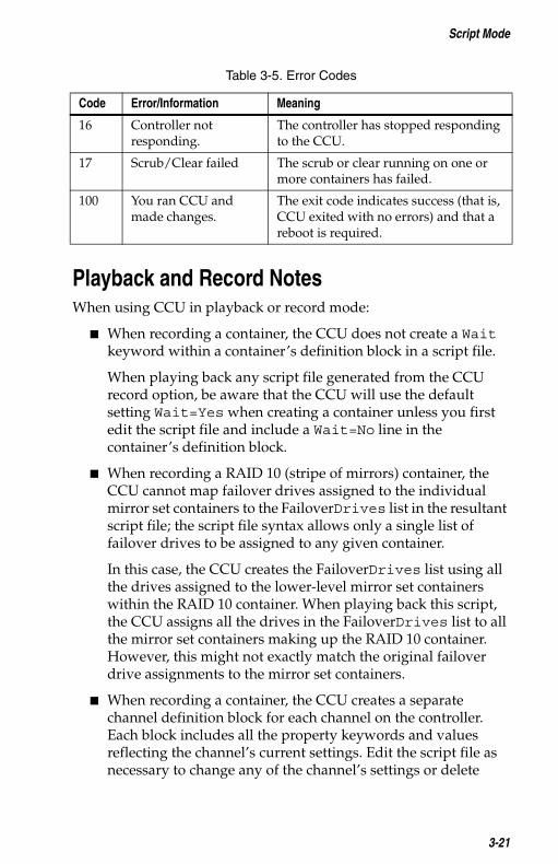
Table 3-5 lists the possible status codes returned by the CCU.
ControllerID Specifies the SCSI ID of the controller on the channel. Normally, the controller is assigned SCSI ID 7 on each of its channels. You can specify any ID value between 0 and 15.If you do not specify a ControllerID keyword for the channel, the channel’s current controller ID setting is not changed.Example:
ControllerID=15
Table 3-5. Error Codes
Code Error/Information Meaning
0 You ran CCU and made no changes.
This exit code indicates success (that is, the CCU exited with no errors) and that no report is required.
1 No Controller Found. The CCU did not detect any controllers in the system.
Table 3-4. Channel Definition Block Properties
3-19

Adaptec SCSI RAID Container Configuration Utility User’s Guide
2 Syntax or logical error in the script file.
The CCU encountered an invalid command or keyword in the specified script file.
3 Unable to open file. The CCU was unable to open the specified script or log file.
4 Error in the command line parameters.
You passed an invalid command-line switch to the CCU. (See Script Mode on page 3-1 for the list of valid command switches.)
5 Unable to read system configuration.
The CCU was unable to get the configuration information from the specified controller.
6 No drives detected. The CCU did not detect any disk drives attached to the selected controller.
7 Specified drive not found in system.
The disk drive you specified does not exist on the selected controller.
8 Specified container size too small.
You specified a container size that is smaller than the minimum size allowed for this container.
9 Specified container size too big.
You specified a container size that is larger than the maximum size allowed for this container.
10 Number of drives do not match the container type.
The number of drives you selected is invalid for the type of container specified.
11 Unable to initialize drive.
The CCU was unable to initialize one or more disk drives.
12 Error occurred while creating container.
The CCU encountered an error creating a container.
13 Too many failover drives assigned.
You attempted to assign more than the maximum number of failover drives allowed for the specified container.
14 Insufficient memory to run the application.
There is not enough memory to run the CCU.
15 Incorrect controller The controller number you specified is
Table 3-5. Error Codes
Code Error/Information Meaning
3-20
number. invalid or out-of-range.
Script Mode
Playback and Record NotesWhen using CCU in playback or record mode:
� When recording a container, the CCU does not create a Wait keyword within a container’s definition block in a script file.
When playing back any script file generated from the CCU record option, be aware that the CCU will use the default setting Wait=Yes when creating a container unless you first edit the script file and include a Wait=No line in the container’s definition block.
� When recording a RAID 10 (stripe of mirrors) container, the CCU cannot map failover drives assigned to the individual mirror set containers to the FailoverDrives list in the resultant script file; the script file syntax allows only a single list of failover drives to be assigned to any given container.
In this case, the CCU creates the FailoverDrives list using all the drives assigned to the lower-level mirror set containers within the RAID 10 container. When playing back this script, the CCU assigns all the drives in the FailoverDrives list to all the mirror set containers making up the RAID 10 container. However, this might not exactly match the original failover drive assignments to the mirror set containers.
� When recording a container, the CCU creates a separate channel definition block for each channel on the controller. Each block includes all the property keywords and values reflecting the channel’s current settings. Edit the script file as necessary to change any of the channel’s settings or delete
16 Controller not responding.
The controller has stopped responding to the CCU.
17 Scrub/Clear failed The scrub or clear running on one or more containers has failed.
100 You ran CCU and made changes.
The exit code indicates success (that is, CCU exited with no errors) and that a reboot is required.
Table 3-5. Error Codes
Code Error/Information Meaning
3-21
Adaptec SCSI RAID Container Configuration Utility User’s Guide
keywords to ensure the controller’s corresponding channel setting is not changed.
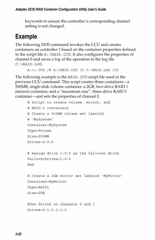
ExampleThe following DOS command invokes the CCU and creates containers on controller 1 based on the container properties defined in the script file A:\RAID.CCU. It also configures the properties of channel 0 and saves a log of the operation in the log file C:\RAID.LOG.
A:\> CCU /P A:\RAID.CCU /L C:\RAID.LOG /C1
The following example is the RAID.CCU script file used in the previous CCU command. This script creates three containers—a 500MB, single-disk volume container; a 2GB, two-drive RAID 1 (mirror) container; and a “maximum size”, three-drive RAID 5 container—and sets the properties of channel 0.
# Script to create volume, mirror, and
# RAID-5 containers
# Create a 500MB volume set labeled
# ‘MySystem’
Container=MySystem
Type=Volume
Size=500MB
Drives=0:0:0
# Assign drive 1:0:0 as the failover drive.
FailoverDrives=1:0:0
End
# Create a 2GB mirror set labeled ‘MyMirror’
Container=MyMirror
Type=RAID1
Size=2GB
#Use drives on channels 0 and 1
Drives=0:1:0,1:1:0
3-22

Script Mode
# Disable write cache
WriteCache=No
#Assign 2 failover drives
FailoverDrives=1:2:0, 1:3:0
End
# Create a maximum size RAID 5 set labeled
# ‘MyData’
Container=MyData
Type=RAID5
Size=Maximum
# Use the maximum stripe size
StripeSize=64
# Clear the container (don’t scrub it)
Method=Clear
#Don’t wait for clear to complete
Wait=No
#Use drives 2, 3, 4 on channel 0
Drives=0:2:0, 0:3:0, 0:4:0
#Assign failover drives
FailoverDrives=1:1:0,1:2:0
End
# Set Channel 0 properties
Channel=0
3-23

Adaptec SCSI RAID Container Configuration Utility User’s Guide
# Set the controller’s SCSI ID to 7
ControllerID=7
End
❒
3-24

Index
/C switch 3-3/L switch 3-3/P switch 3-2/R switch 3-2
Aadapters
cold-swapping 2-8hot-swapping 2-8
Assigned failover drives list 2-5removing drives 2-5
BBIOS
accessing the CCU 1-1detecting new hardware 2-8
bootable containers 2-6
CCCU
/C switch 3-3/L switch 3-3/P switch 3-2/R switch 3-2accessing
from BIOS 1-1from MS-DOS 1-1
command-line switches 3-2example 3-22interactive mode 2-1
overview 1-1
initializing drives 3-5properties 3-4
record mode 3-2running 1-2script mode 3-1
overview 1-1playback mode 3-3 to 3-6record mode 3-6 to 3-24switches 3-2
shared channels 1-2supported container types 3-6user notes 3-21
channel definition blockChannel keyword 3-18ControllerID keyword 3-19End keyword 3-18overview 3-18
Channel propertychannel definition block 3-18
clear status 3-6cold-swapping adapters 2-8command-line switches 3-2comments, in script files 3-9container definition block
Container keyword 3-12definition 3-8Drives keyword 3-12End keyword 3-13FailoverDrives keyword 3-13InitializeAll keyword 3-14Method keyword 3-15properties 3-9ReadCache keyword 3-15
Index-1
overview 1-1playback mode 3-2
required keywords 3-9Size keyword 3-16
Adaptec SCSI RAID Container Configuration Utility User’s Guide
StripeSize keyword 3-11Type keyword 3-12Wait keyword 3-17WaitForScrub keyword 3-17WriteCache keyword 3-17
Container Properties dialog box 2-4deleting containers 2-7
Container Properties menu 2-2Container property, container
definition block 3-12containers
bootable 2-6creating 2-1deleting 2-7displaying associated disks 2-5managing 2-4minimum drives 2-2multilevel, and scrub tasks 3-7properties 2-2
Drives 3-4FailoverDrives 3-4Label 3-4ReadCache 3-4Size 3-4StripeSize 3-4Type 3-4WriteCache 3-4
read caching 2-4selecting partitions 2-1size 2-3stripe size 2-3types 3-6types of 2-2viewing properties 2-4write caching 2-4
controller number, specifying 3-3ControllerID property
channel definition block 3-19
Ddeleting containers 2-7deselecting drives 2-2disks
displaying associated 2-5initializing drives 2-6
DOS, accessing the CCU 1-1drives
deselecting 2-2failover 2-5initializing 3-5minimum required 2-2
Drives propertycontainer definition block 3-12initializing drives 3-5overview 3-4
EEnd property
channel definition block 3-18container definition block 3-13
error handlinglist of codes 3-19script mode 3-19
ERRORLEVEL variable 3-19
Ffailover drives 2-5Failover Management for Container
dialog box 2-5FailoverDrives keyword
container definition block 3-13FailoverDrives property 3-4freespace, displaying 2-1
H
Index-2
description 3-5creating containers 2-1 hot-swapping adapters 2-8

Index
Iinitialize
disk drivesinteractive mode 2-6script mode 3-5
Initialize Drives option 2-6InitializeAll property
container definition block 3-14description 3-5
interactive mode 2-1overview 1-1
LLabel property 3-4List of Containers dialog box 2-4
assigning failover drives 2-5removing failover drives 2-5
log filessample 3-7switch 3-3
MManage Container option 2-4
deleting containers 2-7making a container bootable 2-6
Manage Containers dialog boxassigning and removing failover
drives 2-5removing failover drives 2-5
managing containers 2-4Method property, container
definition block 3-15mirror set, description 2-2
Ppartitions 2-1playback mode
properties 3-4scrub status 3-6switch 3-2user notes 3-21
propertiescontainer 2-2
viewing 2-4container definition block 3-9ControllerID 3-5Drives 3-4FailoverDrives 3-4InitializeAll 3-5Label 3-4playback mode 3-4ReadCache 3-4Size 3-4StripeSize 3-4, 3-16Type 3-4WriteCache 3-4
RRAID 0 container, description 2-2RAID 1 container, description 2-2RAID 10 containers
description 2-3scrub operations on 3-8
RAID 5 container, description 2-3RAID 50 containers
description 2-3scrub/clear operations on 3-8
RAID10 containersdisplaying associated disks 2-5
read caching 2-4ReadCache property
container definition block 3-15description 3-4
record modecontainer definition block 3-8script file syntax 3-8
Index-3
clear status 3-6initializing drives 3-5
switch 3-2user notes 3-21

Adaptec SCSI RAID Container Configuration Utility User’s Guide
removing failover drives 2-5running the CCU 1-2
Sscript files
syntax 3-8comments in 3-9
script mode 3-1command-line switches 3-2
error handling 3-19overview 1-1
scrub tasks
determining status 3-6on multilevel containers 3-7
Select failover drives list 2-5shared channels 1-2
Size propertycontainer definition block 3-16description 3-4
status, of scrub or clear 3-7stripe of mirrors, description 2-3stripe of RAID5, description 2-3stripe set, description 2-2
stripe size 2-3StripeSize property 3-16
description 3-4
supported container types 3-6syntax of script files 3-8
TType property
container definition block 3-12
description 3-4
V
WWait property, container definition
block 3-17WaitForScrub property, container
definition block 3-17write caching 2-4WriteCache property
container definition block 3-17description 3-4
Index-4
volume container 2-2

©2000 – 2002 AdaptecAll rights reserved. Adaptec and the Adaptec logoare trademarks of Adaptec which may be registered in some jurisdictions.
Part Number: 513131-06, Ver. AA SEF 01/02
Adaptec, Inc.691 South Milpitas BoulevardMilpitas, CA 95035 USA
R