adafruit 16-channel pwm/servo shield - cdn-reichelt.de · overview driving servo motors with the...
TRANSCRIPT

Adafruit 16-channel PWM/Servo ShieldCreated by lady ada
Last updated on 2018-01-16 12:20:38 AM UTC
235
13131313141415
1718
202020212121
212122
2323232323
23232323
2325252525
26262626
Guide Contents
Guide ContentsOverviewAssemblyShield ConnectionsPins UsedConnecting other I2C devicesPowering Servos / PWM
Adding a Capacitor to the thru-hole capacitor slotConnecting a ServoAdding More Servos
Stacking ShieldsAddressing the Shields
Using the Adafruit LibraryInstall Adafruit PCA9685 libraryTest with the Example Code:
If using a Breakout:If using a Shield:If using a FeatherWing:
Connect a ServoCalibrating your ServosConverting from Degrees to Pulse Length
Library ReferencesetPWMFreq(freq)
DescriptionArgumentsExample
setPWM(channel, on, off)DescriptionArgumentsExample
Using as GPIOFAQ
Can this board be used for LEDs or just servos?I am having strange problems when combining this shield with the Adafruit LED Matrix/7Seg BackpacksWith LEDs, how come I cant get the LEDs to turn completely off?
Downloads & LinksFilesSchematicFabrication Print
© Adafruit Industries https://learn.adafruit.com/adafruit-16-channel-pwm-slash-servo-shield Page 2 of 27

Overview
Driving servo motors with the Arduino Servo library is pretty easy, but each one consumes a precious pin - not tomention some Arduino processing power. The Adafruit 16-Channel 12-bit PWM/Servo Driver Shield will drive up to 16servos over I2C with only 2 pins. The on-board PWM controller will drive all 16 channels simultaneously with noadditional Arduino processing overhead. What's more, you can stack up to 62 of them to control even more servos - allwith the same 2 pins!
The Adafruit PWM/Servo Driver is the perfect solution for any project that requires a lot of servos!
© Adafruit Industries https://learn.adafruit.com/adafruit-16-channel-pwm-slash-servo-shield Page 3 of 27

© Adafruit Industries https://learn.adafruit.com/adafruit-16-channel-pwm-slash-servo-shield Page 4 of 27

Assembly
Check you have everything you need: assembled shield
PCB, 0.1" male header, 4 of 3x4 male header, and a 2
pin terminal block
Break apart the 0.1" header into 6, 8 and/or 10-pin long
pieces and slip the long ends into the headers of your
Arduino
This section assumes you do not want to stack the shield with stacking headers. If you want to stack anothershield on top, skip to the Stacking Shields section!
© Adafruit Industries https://learn.adafruit.com/adafruit-16-channel-pwm-slash-servo-shield Page 5 of 27

Place the shield on top of the header pins, they should
fit into each of the holes along the edge
Solder each of the pins to secure the shield to the
headers
© Adafruit Industries https://learn.adafruit.com/adafruit-16-channel-pwm-slash-servo-shield Page 6 of 27

© Adafruit Industries https://learn.adafruit.com/adafruit-16-channel-pwm-slash-servo-shield Page 7 of 27

Place the 2 pin terminal block so it faces out. Also place
the 3x4 headers so the short pins are plugged into the
shield and the long pins are sticking up
To keep them in place, a few pieces of tape will hold
them for when you flip the board over.
© Adafruit Industries https://learn.adafruit.com/adafruit-16-channel-pwm-slash-servo-shield Page 8 of 27

Flip the board over and solder the terminal block
Then solder one pin of each 3x4 header to tack them in
place.
© Adafruit Industries https://learn.adafruit.com/adafruit-16-channel-pwm-slash-servo-shield Page 9 of 27
© Adafruit Industries https://learn.adafruit.com/adafruit-16-channel-pwm-slash-servo-shield Page 10 of 27

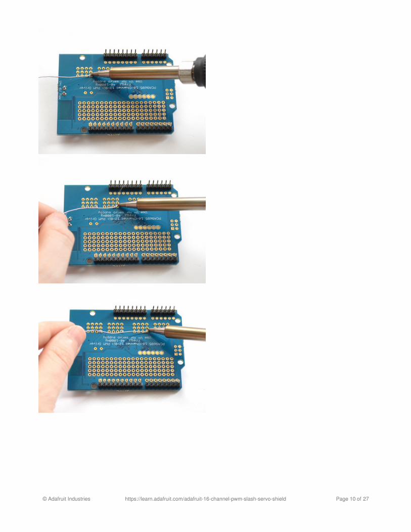
Finally...solder every pin of the 3x4 headers
© Adafruit Industries https://learn.adafruit.com/adafruit-16-channel-pwm-slash-servo-shield Page 11 of 27

You're done! Go onto the next sections to learn how to
use your servo/pwm shield
© Adafruit Industries https://learn.adafruit.com/adafruit-16-channel-pwm-slash-servo-shield Page 12 of 27

Shield ConnectionsPins UsedThe shield plugs in directly into any shield-compatible Arduino such as Duemilanove, Diecimila, UNO, Leonardo, MegaR3+, ADK R3+. The only pins required to run are the Ground, 5V and SDA + SCL I2C control pins.
For backwards compatibility with old Ardunos, SCL is connected to A5 and SDA is connected to A4. UNOs alreadyhave this connection on board. If you are using a Leonardo or Mega and want to use the A4/A5 pins, cut the traces onthe top of the board between A4 and A5 and the two pins next to them labeled SCL/SDA.
If you are using a Mega or ADK R2 or earlier, you will have to solder a wire from SCL to D21 and SDA to D20
Connecting other I2C devicesSince I2C is a 'shared bus' you can still connect other I2C devices to the SDA/SCL pins as long as they do not have aconflicting address. The default address for the shield is address 0x40
Powering Servos / PWMThis shield has two power supplies. One is VCC - that is the 5V power from the Arduino, it is used to power the PWMchip and determines the I2C logic level and the PWM signal logic level. When this power supply is working you willsee a red LED. The red LED must be lit for the Arduino & shield to work! Plug in the Arduino to USB or a wall adapterto provide it.
To power servos you will need to also connect the V+ power supply - this is the power supply for the servos. (If youare lighting up single LEDs you may not need this power supply.) This power supply should be 5 or 6VDC. You canconnect this power through the blue terminal block. There is reverse-polarity protection in case you hook up powerbackwards.
Nearly all servos are designed to run on about 5 or 6v. Keep in mind that a lot of servos moving at the same time(particularly large powerful ones) will need a lot of current. Even micro servos will draw several hundred mA whenmoving. Some High-torque servos will draw more than 1A each under load.
Good power choices are:
5v 2A switching power supply (up to perhaps 4 servos)
© Adafruit Industries https://learn.adafruit.com/adafruit-16-channel-pwm-slash-servo-shield Page 13 of 27

5v 10A switching power supply (up to perhaps 16 servos)4xAA Battery Holder - 6v with Alkaline cells. 4.8v with NiMH rechargeable cells, portable!4.8 or 6v Rechargeable RC battery packs from a hobby store.
Adding a Capacitor to the thru-hole capacitor slotWe have a spot on the PCB for soldering in an electrolytic capacitor. Based on your usage, you may or may not need acapacitor. If you are driving a lot of servos from a power supply that dips a lot when the servos move, n * 100uF wheren is the number of servos is a good place to start - eg 470uF or more for 5 servos. Since its so dependent on servocurrent draw, the torque on each motor, and what power supply, there is no "one magic capacitor value" we cansuggest which is why we don't include a capacitor in the kit.
Connecting a ServoMost servos come with a standard 3-pin female connector that will plug directly into the headers on the Servo Driver.Be sure to align the plug with the ground wire (usually black or brown) with the bottom row and the signal wire (usuallyyellow or white) on the top.
SERVOS CAN USE A LOT OF POWER! It is not a good idea to use the Arduino 5v pin to power your servos.Electrical noise and 'brownouts' from excess current draw can cause your Arduino to act erratically, resetand/or overheat.
© Adafruit Industries https://learn.adafruit.com/adafruit-16-channel-pwm-slash-servo-shield Page 14 of 27

Adding More ServosUp to 16 servos can be attached to one board. If you need to control more than 16 servos, additional boards can bestacked as described on the next page.
© Adafruit Industries https://learn.adafruit.com/adafruit-16-channel-pwm-slash-servo-shield Page 15 of 27

© Adafruit Industries https://learn.adafruit.com/adafruit-16-channel-pwm-slash-servo-shield Page 16 of 27

Stacking ShieldsIf you want to plug shields on top of this one, make sure you pick up a set of shield-stacking headers http://www.adafruit.com/product/85and solder them instead of the male header
Since this shield only uses the I2C pins and the I2C bus is sharable, you can stack multiple shields on top of eachother. You will need to have installed stacking headers & right angle 3x4 connections for it to physically connect.Multiple shields (up to 62!) can be stacked to control still more servos.
You may have difficulty with the 'left-most' header since we updated the transistor to be beefier. Use the 3 ports to theright or solder wires out to get mechanical access
© Adafruit Industries https://learn.adafruit.com/adafruit-16-channel-pwm-slash-servo-shield Page 17 of 27

Addressing the ShieldsEach board in the chain must be assigned a unique address. This is done with the address jumpers on the upper rightedge of the board. The I2C base address for each board is 0x40. The binary address that you program with theaddress jumpers is added to the base I2C address.
To program the address offset, use a drop of solder to bridge the corresponding address jumper for each binary '1' inthe address.
© Adafruit Industries https://learn.adafruit.com/adafruit-16-channel-pwm-slash-servo-shield Page 18 of 27

Board 0: Address = 0x40 Offset = binary 00000 (no jumpers required)Board 1: Address = 0x41 Offset = binary 00001 (bridge A0 as in the photo above)Board 2: Address = 0x42 Offset = binary 00010 (bridge A1)Board 3: Address = 0x43 Offset = binary 00011 (bridge A0 & A1)Board 4: Address = 0x44 Offset = binary 00100 (bridge A2)
etc.
© Adafruit Industries https://learn.adafruit.com/adafruit-16-channel-pwm-slash-servo-shield Page 19 of 27

Using the Adafruit LibrarySince the PWM Servo Driver is controlled over I2C, its super easy to use with any microcontroller or microcomputer. Inthis demo we'll show using it with the Arduino IDE but the C++ code can be ported easily
Install Adafruit PCA9685 library
To begin reading sensor data, you will need to install the Adafruit_PWMServo library (code on our github repository). Itis available from the Arduino library manager so we recommend using that.
From the IDE open up the library manager...
And type in adafruit pwm to locate the library. Click Install
We also have a great tutorial on Arduino library installation at:http://learn.adafruit.com/adafruit-all-about-arduino-libraries-install-use
Test with the Example Code:
First make sure all copies of the Arduino IDE are closed.
Next open the Arduino IDE and select File->Examples->Adafruit_PWMServoDriver->Servo. This will open the examplefile in an IDE window.
© Adafruit Industries https://learn.adafruit.com/adafruit-16-channel-pwm-slash-servo-shield Page 20 of 27

If using a Breakout:
Connect the driver board and servo as shown on the previous page. Don't forget to provide power to both Vin (3-5Vlogic level) and V+ (5V servo power). Check the green LED is lit!
If using a Shield:
Plug the shield into your Arduino. Don't forget you will also have to provide 5V to the V+ terminal block. Both red andgreen LEDs must be lit.
If using a FeatherWing:
Plug the FeatherWing into your Feather. Don't forget you will also have to provide 5V to the V+ terminal block. Checkthe green LED is lit!
Connect a Servo
A single servo should be plugged into the PWM #0 port, the first port. You should see the servo sweep back and forthover approximately 180 degrees.
Calibrating your Servos
Servo pulse timing varies between different brands and models. Since it is an analog control circuit, there is oftensome variation between samples of the same brand and model. For precise position control, you will want to calibratethe minumum and maximum pulse-widths in your code to match known positions of the servo.
Find the Minimum:Using the example code, edit SERVOMIN until the low-point of the sweep reaches the minimum range of travel. It isbest to approach this gradually and stop before the physical limit of travel is reached.
Find the Maximum:
© Adafruit Industries https://learn.adafruit.com/adafruit-16-channel-pwm-slash-servo-shield Page 21 of 27

Again using the example code, edit SERVOMAX until the high-point of the sweep reaches the maximum range oftravel. Again, is best to approach this gradually and stop before the physical limit of travel is reached.
Converting from Degrees to Pulse LengthThe Arduino "map()" function is an easy way to convert between degrees of rotation and your calibrated SERVOMINand SERVOMAX pulse lengths. Assuming a typical servo with 180 degrees of rotation; once you have calibratedSERVOMIN to the 0-degree position and SERVOMAX to the 180 degree position, you can convert any angle between0 and 180 degrees to the corresponding pulse length with the following line of code:
Use caution when adjusting SERVOMIN and SERVOMAX. Hitting the physical limits of travel can strip thegears and permanently damage your servo.
pulselength = map(degrees, 0, 180, SERVOMIN, SERVOMAX);
© Adafruit Industries https://learn.adafruit.com/adafruit-16-channel-pwm-slash-servo-shield Page 22 of 27

Library ReferencesetPWMFreq(freq)
Description
This function can be used to adjust the PWM frequency, which determines how many full 'pulses' per second aregenerated by the IC. Stated differently, the frequency determines how 'long' each pulse is in duration from start tofinish, taking into account both the high and low segments of the pulse.
Frequency is important in PWM, since setting the frequency too high with a very small duty cycle can cause problems,since the 'rise time' of the signal (the time it takes to go from 0V to VCC) may be longer than the time the signal isactive, and the PWM output will appear smoothed out and may not even reach VCC, potentially causing a number ofproblems.
Arguments
freq: A number representing the frequency in Hz, between 40 and 1000
Example
The following code will set the PWM frequency to the maximum value of 1000Hz:
setPWM(channel, on, off)
Description
This function sets the start (on) and end (off) of the high segment of the PWM pulse on a specific channel. You specifythe 'tick' value between 0..4095 when the signal will turn on, and when it will turn off. Channel indicates which of the16 PWM outputs should be updated with the new values.
Arguments
channel: The channel that should be updated with the new values (0..15)on: The tick (between 0..4095) when the signal should transition from low to highoff:the tick (between 0..4095) when the signal should transition from high to low
Example
The following example will cause channel 15 to start low, go high around 25% into the pulse (tick 1024 out of 4096),transition back to low 75% into the pulse (tick 3072), and remain low for the last 25% of the pulse:
Using as GPIO
There's also some special settings for turning the pins fully on or fully off
You can set the pin to be fully on with
pwm.setPWMFreq(1000)
pwm.setPWM(15, 1024, 3072)
© Adafruit Industries https://learn.adafruit.com/adafruit-16-channel-pwm-slash-servo-shield Page 23 of 27

pwm.setPWM(pin, 4096, 0);
You can set the pin to be fully off with
pwm.setPWM(pin, 0, 4096);
© Adafruit Industries https://learn.adafruit.com/adafruit-16-channel-pwm-slash-servo-shield Page 24 of 27

FAQCan this board be used for LEDs or just servos?
It can be used for LEDs as well as any other PWM-able device!
I am having strange problems when combining this shield with the Adafruit LED Matrix/7Seg Backpacks
The PCA9865 chip has an "All Call" address of 0x70. This is in addition to the configured address. Set thebackpacks to address 0x71 or anything other than the default 0x70 to make the issue go away.
With LEDs, how come I cant get the LEDs to turn completely off?
If you want to turn the LEDs totally off use setPWM(pin, 4096, 0); not setPWM(pin, 4095, 0);
© Adafruit Industries https://learn.adafruit.com/adafruit-16-channel-pwm-slash-servo-shield Page 25 of 27

Downloads & LinksFiles
PCA9685 datasheetAdafruit PWM/Servo Driver Library in GitHubAdafruit Fritzing LibraryEagleCAD PCB files on GitHub
Schematic
Fabrication Print
© Adafruit Industries https://learn.adafruit.com/adafruit-16-channel-pwm-slash-servo-shield Page 26 of 27

© Adafruit Industries Last Updated: 2018-01-16 12:20:37 AM UTC Page 27 of 27