ad hoc networks - inhansl.inha.ac.kr/wikipages/files/uant_adhoc.pdf · hard to even have a static...
TRANSCRIPT

Ad Hoc Networks 34 (2015) 252–264
Contents lists available at ScienceDirect
Ad Hoc Networks
journal homepage: www.elsevier .com/locate /adhoc
Software-defined underwater acoustic networking platformand its applications
http://dx.doi.org/10.1016/j.adhoc.2015.01.0101570-8705/� 2015 Elsevier B.V. All rights reserved.
⇑ Corresponding author. Tel.: +82-32-860-7445.E-mail address: [email protected] (Y. Noh).
Dustin Torres a, Jonathan Friedman a, Thomas Schmid b, Mani B. Srivastava a,Youngtae Noh c,⇑, Mario Gerla d
a Electrical Engineering Department, University of California at Los Angeles (UCLA), United Statesb Electrical and Computer Engineering Department at the University of Utah, United Statesc Department of Computer Science and Information Engineering, Inha University, South Koread Computer Science, University of California at Los Angeles (UCLA), United States
a r t i c l e i n f o
Article history:Received 2 March 2014Received in revised form 19 December 2014Accepted 21 January 2015Available online 31 January 2015
Keywords:Underwater acoustic networkingSoftware defined radioTime synchronizationChannel allocation protocols
a b s t r a c t
As underwater communications adopt acoustics as the primary modality, we are confront-ing several unique challenges such as highly limited bandwidth, severe fading, and longpropagation delay. To cope with these, many MAC protocols and PHY layer techniques havebeen proposed. In this paper, we present a research platform that allows developers toeasily implement and compare their protocols in an underwater network and configurethem at runtime. We have built our platform using widely supported software that hasbeen successfully used in terrestrial radio and network development. The flexibility ofdevelopment tools such as software defined radio, TinyOS, and Linux have provided theability for rapid growth in the community. Our platform adapts some of these tools to workwell with the underwater environment while maintaining flexibility, ultimately providingan end-to-end networking approach for underwater acoustic development. To show itsapplicability, we further implement and evaluate channel allocation and time synchroniza-tion protocols on our platform.
� 2015 Elsevier B.V. All rights reserved.
1. Introduction
The underwater medium presents many challenges fordigital communication. There is limited availablebandwidth and high bit error rates caused by multipath,fading, and long propagation delay. The speed of sound isfive orders of magnitude less than that of terrestrial radio,which can make it hard for underwater networks tosynchronize, exchange data, update routes, and communi-cate efficiently.
Due to the severity of multipath underwater, a receivingnode might be at a point where there is little energy in the
received signal making it hard to receive without errors[1]. These spots of destructive multipath interference varywith time due to the movement of water, and make it quitehard to even have a static network topology. Along withmultipath, other unfavorable characteristics such asambient noise, bubbles, surface scattering, and slow prop-agation speed make developing underwater networks adifficult task [1].
Furthermore, the ocean varies significantly both tempo-rally and spatially, which makes it challenging to create amodel of a ‘‘typical’’ underwater acoustic channel [1]. Sincethere is no ‘‘typical’’ model, there is no single networkarchitecture that works best in all situations. Therefore,depending on the current characteristics of the channel,there is a variable amount of bandwidth, various noise

D. Torres et al. / Ad Hoc Networks 34 (2015) 252–264 253
sources in different frequency bands, varying inter-symbolinterference (ISI) depending on the water depth, and manyother characteristics under consideration. Even if thechannel noise is known, attenuation still depends on bothdistance and frequency, along with space and time varyingmultipath [2].
We present a software defined Underwater AcousticNetworking plaTform (UANT) to aid development ofunderwater acoustic networks. A software defined systemcan help to address the constantly changing underwateracoustic channel by way of reconfigurability. A flexibleapproach allows for system parameters at all layers to beeasily modified without the need for specialized hardware.UANT uses GNU Radio, a software defined radio frame-work, to achieve configurability at the physical layer. Tiny-OS has been widely adopted for the use on sensor networkplatforms and provides a full network stack. We adaptedthese widely supported tools that have proven effectiveprototyping, development, and implementation for terres-trial networks to be used in UANT.
Since the characteristics of the underwater acousticchannel cannot be properly modeled with a static configu-ration, it is important to be able to change the properties ofan acoustic modem at run time. UANT has the flexibility ofsoftware defined radios and the advantages of the networklayers of TinyOS and Linux, ultimately providing and end-to-end network for easy underwater development from thephysical to application layer. This paper significantlyenhances our earlier work [3] as follows:
� We add Applications and protocol implementation onUANT section to show UANT’s applicability and discusschannel allocation protocol’s detailed description(Section 4).� We implement and evaluate channel allocation protocol
and time synchronization protocol (THSL) on our pro-posed underwater acoustic networking platform (Sec-tion 6.2 and 6.3 respectively).
2. Background
Software defined techniques have been of interest inrecent years not only for terrestrial radios but also acous-tics and ultrasonics [4]. Jones et al. described some of thebenefits to the use of software define radio for underwateruse [5]. They talked about the possibility to improveunderwater acoustic performance by using methods thathave worked well with terrestrial radios such as Cognitiveradio via software defined techniques.
Sözer and Stojanovic developed rModem [6] to achievea similar goal of having a configurable acoustic modem.However, the rModem is a standalone board that uses anFPGA and DSP. Furthermore, rModem focuses on lower lay-ers and does not provide an end-to-end networking envi-ronment, making it hard to study the impact on actualapplications. We hope to supplement platforms such asthe rModem by aiding research in MAC and PHY layer pro-tocols that can ultimately be implemented on standalonenodes to create an underwater network.
2.1. GNU Radio and USRP
Software defined radio has received a lot of attentionmost notably in the research community. The ability touse software to modulate and manipulate the receivedand transmitted signals allows for rapid developmentwithout the need or cost of specialized hardware. GNURadio [7], one of the most popular SDR frameworks, iscomprised of a flow graph and signal processing blocks.The signal processing blocks are written in C++ and act asthe ‘‘heavy lifters’’ whereas the flow graph is setup inPython in order to move data from one block to the next.In this way many modulation schemes can be createdusing standard C++ blocks (already included in GNU Radio)and connecting them together in a flow graph. There is alarge community of users who have contributed to thisopen source project, both signal processing blocks as wellas various applications. The many contributions have ledto a large library of modulation schemes including GMSK,PSK, QAM, CPM, OFDM, and more.
We use GNU Radio along with the Universal SoftwareRadio Peripheral version 1 (USRP1) to achieve underwateracoustic communication. The USRP created by EttusResearch [8], is a radio front-end that is commonly usedwith GNU Radio. Although the option of using a sound cardprovides a low cost solution, the USRP offers a wider fre-quency range as well as more dedicated hardware. TheUSRP has a total of 4 ADCs and 4 DACs allowing for up to16 MHz of bandwidth each way, which is proficient forthe underwater acoustic channel. We have modified anexample application used for digital communications bun-dled with GNU Radio to use the USRP as a NIC via the TUN/TAP interface. This allows for wireless communicationsbetween two computers using software defined radio thatcan run networking applications over TCP.
2.2. TinyOS and TOSSIM
TinyOS is a widely used sensor network operating sys-tem created at University of California, Berkeley and meantfor sensor nodes requiring concurrency and flexibilitywhile being limited to resource constraints [9]. TinyOS isimplemented in the NesC language, which supports theconcurrency model needed for sensor networks. TinyOSis widely used both in commercial applications as well asin academics for research purposes. There is a large userbase who constantly contribute to the open source project,which allows UANT to always benefit from the newest pro-tocols. For instance, Washington University contributed aMAC Layer Architecture [10] to provide the MAC layer withmany commonly needed functions for MAC protocols.
Generally TinyOS is compiled for a sensor network plat-form, with a network stack in accordance with the specificradio being used. However to gain the benefits of usingTinyOS in UANT we have chosen to use TOSSIM [11], whichsimulates sensor network nodes on a PC. TOSSIM was cre-ated in order to support compiling TinyOS componentgraphs into a simulation for a PC. It utilizes a discrete eventqueue, reimplements some of the sensor nodes hardware,models the radio and ADC of a mote, and most importantlyfor UANT, uses communication services for external

254 D. Torres et al. / Ad Hoc Networks 34 (2015) 252–264
programs to communicate with the running simulationover TCP sockets [11]. TOSSIM fully supports the TinyOStoolchain making it effortless to transition from simulationto real network, or vice versa. TOSSIM executes in a similarfashion to a real mote, with each simulation having anotion of a virtual clock running at 4 MHz. TOSSIM usesinterrupts similar to that of a mote, however when anevent fires, the simulation calls an interrupt handler in ahardware abstraction component. In UANT, TOSSIM is notused as a simulation framework but rather the real timerunning nodes, this is explained in greater detail in thenext section.
3. System architecture
UANT has been created as a platform to allow testing ofnew protocols and modulation schemes on a fully func-tional underwater network. We used open source software(GNU Radio and TinyOS) that is widely supported and hasbeen in use for many years. TinyOS applications are able tobe incorporated into UANT simply by changing the config-uration file to match the needs of the specific application.The running application can be easily monitored in Linuxeither by monitoring the TOSSIM simulation through cur-rently supported techniques such as debug statements, orpackets being forwarded over a TCP socket where theraw bytes of transmitted or received packets can beviewed, or both. Along with running TinyOS applications,it is possible to assign an IP addresses to the TOSSIM nodein order to inject TCP/IP packets and use a wide variety ofLinux applications to send data between nodes. UANT usesTOSSIM to run TinyOS applications and components on aPC in real-time fashion rather than being used as a simula-tor. This is similar to EmTos [12] where a wrapper around aTinyOS application is used to run on an EmStar node. It isimportant to note that each node in UANT is running in adifferent TOSSIM simulation. This allows the ability forevery node to run a unique and different application,which is not possible in a single TOSSIM simulation.
Although the non-negligible latency introduced fromsamples traveling from the hardware frontend to softwarecan make it difficult to develop a MAC layer for SDR, thelong propagation delay of the underwater channel makesit possible to ignore this latency. Nychis et al. [13] used‘‘split-functionality’’ in order to take advantage of the min-imal latency on the USRP, yet still maintaining the controlof the data flow in the host CPU. Yang et al. [14] recentlydemonstrated the benefits of parallelization in embeddedrealizations on SDR platforms in order to achieve a highdegree of flexibility while satisfying the hard real-timeconstraints. As another branch of recent work, Truonget al. analyzed the sources of the latency and quantifiedthem by using both analytical and experimental methods[15,16].
However, with the slow propagation delay of the under-water acoustic medium, the added bus latency betweenthe USRP and the MAC layer implemented on the hostmachine can be considered negligible. The speed of soundunderwater is 1500 m/s, so for two nodes that are 1.5 kmapart the propagation delay is approximately one second.In [17], Schmid et al. measured SDR latency and character-
ized the round trip time to and from the USRP to bebetween 3 ms and 26.5 ms. The 26.5 ms measurementincluded host processing of the 802.15.4 protocol, while3 ms is the theoretical latency to and from the host assum-ing no computation is done on the host machine. Althoughin terrestrial radio this latency makes some MAC protocolssuch as TDMA hard to implement, for underwater acous-tics this is.3% of the propagation delay for nodes 1.5 kmapart.
3.1. Architecture
UANT provides reconfigurability at the physical layer,the MAC layer, and the application layer. With control overthese layers, we aim to provide a way to implement andcompare proposed underwater MAC protocols and PHYlayer techniques in the presence of a network runningapplications from Linux or TinyOS. Although UANT mustbe run on a PC, we tried to keep in mind that the end goalfor much of the current underwater acoustic communica-tion research is geared toward underwater sensor net-works (USN) and underwater autonomous vehicles (UAV).
3.1.1. OverviewThe flow of data through UANT can be seen in Fig. 1. To
receive packets, an acoustic signal containing data is firstheard by the transducer and passed through to the USRP,which will sample and down convert the data. The datacontinues over USB to software where GNU Radio firstpasses the data through an FFT filter. The streaming sam-ples now represent the complex baseband signal in the fre-quency domain needed for demodulation. Depending onthe modulation scheme that is being used the data willbe processed accordingly. The output of the demodulationblocks is a string of bits which will be fed to a messagequeue in GNU Radio.
GNU Radio is started with a Python script, which estab-lishes the flow graph of C++ blocks for the data to travelthrough. In UANT, the same Python script that is used tostart the flow graph is also used to communicate withTinyOS. Data in the message queue that has been demodu-lated and ready to enter TinyOS must first be packed into aTinyOS serial packet with a one byte modification. If theincoming packet has a broadcast address it is changed tobe the address of the currently running node ID on the hostmachine, which is necessary due to the limitations of theSerialActiveMessages of TinyOS. The packet is then sentover a socket to TOSSIM where it first enters the MAC layer.Depending on what type of message has been received, itwill be properly routed through the TOSSIM simulation,and possibly to Linux via a virtual Ethernet card if required.
3.1.2. UANT: physical layerGNU Radio has been widely adopted by the SDR com-
munity. There has been much advancement in terrestrialradios with the introduction of software defined radio.We have chosen to use GNU Radio for UANT in order totry and bring its success for fast prototyping and develop-ment to the underwater environment. GNU Radio offersmany signal processing blocks that are required for basicand advanced modulation techniques. There have already

Fig. 1. UANT system architecture.
D. Torres et al. / Ad Hoc Networks 34 (2015) 252–264 255
been many modulation schemes implemented in GNURadio using these standard signal processing blocks. Wehave incorporated much of the prior work that has beendone with GNU Radio including these modulation schemesas well as some of the example applications. Specificallywe modified the tunnel example file that allows the USRPboards to be assigned IP addresses and use Linux applica-tions. Modifications that were made include removingthe simplified version of a single CSMA MAC, allowed forslower bit rates that could be desired in a harsh underwa-ter channel, and changed the traffic source and sink fromLinux to TinyOS. Keeping the modifications of the GNURadio example to a minimum allows UANT to use anyfuture expansion to the digital communication examplesto be effortlessly incorporated into our system.
Although currently GNU Radio is too computationallyexpensive for embedded implementations, we preferredthe ability for rapid prototyping and test of PHY and MACeven if it means that our host must be more powerful thansome lower end platforms such as motes. If developmentof network protocols leads to increased performance onUANT it can ultimately be ported to the platform that isused in the USN or UAV, or directly transferred if TinyOSor Linux is used by the system. In addition, we later showthat even with a more capable host UANT is still field-deployable and has been tested in different real worldenvironments. Historically much of the development forGNU Radio has not considered energy savings which isessential for USN; however, there has been some recentwork in this direction. Nychis et al. presented a power sav-ing method for fast pattern detection in order to only passthe received packet over USB if it is in fact intended for thelistening node [13].
3.1.3. UANT: MAC layerOne aspect of GNU Radio that makes it inherently hard
for compatibility with higher layer protocols is the use offlow graphs. We have chosen to use TinyOS to implementthe MAC layer and transition from GNU Radio flow graphsto a packet based system. Mandke et al. used Click todevelop a MAC layer for SDR however all applicationshad to be run in Linux [18]. The reason for using TinyOSin UANT is twofold. First and foremost, much of the moti-vation to advance underwater acoustic communicationcomes from the attempt to further underwater sensor net-works. USN have limited resource constraints and are the
perfect candidate to run TinyOS since it is made specificallyfor this class of device. UANT is designed for research pur-poses specifically on different MAC and PHY layers, butusing TinyOS will allow for an easier transition to anunderwater sensor network node. The second reason wechose TinyOS comes from the fact that there is a largecontributing base of users. This allows for UANT to benefitfrom development of protocols and algorithms for MACand higher layers that are currently implemented as wellas being developed for TinyOS.
As previously mentioned, GNU Radio provides a mes-sage queue which is able to make the transition from astreaming flow of data to a packet which highly facilitatesthe implementation of a MAC layer. In UANT the MAC layersits closest to GNU Radio, in this way any packet that issent to TOSSIM over the serial connection originating atthe transducer will first pass through the MAC. A block dia-gram of the TOSSIM simulation can be seen in Fig. 2. If thepacket has been determined to be a control packet, it willnot proceed further than the MAC layer, and will be actedupon immediately, for instance to send an ACK, CTS, or anyother packet needed for the current protocol in use. How-ever, if the packet is for the running application, it will besent straight through the MAC and control layers to theapplication. The received message is not queued here, itis left up to the application to queue received messages ifneeded. Messages that are to go beyond the MAC layerare only queued if they are intended for Linux via the vir-tual Ethernet card.
3.1.4. UANT: application layerUANT not only provides flexibility at the MAC and PHY
layer, but also gives two options on where to run applica-tions. TinyOS applications that can currently run in TOS-SIM, can be easily integrated into UANT. Theconfiguration file must be wired properly in order to cor-rectly connect the applications components, while theapplication code itself will change very minimally if atall. Using TinyOS in UANT for applications allows todevelop in an environment similar to what could poten-tially run on an USN. These applications along with theMAC layer could be directly implemented on a sensor noderunning TinyOS in the future. For more complex applica-tions we have also provided the ability for Linux to be used.In UANT if this option is enabled, a virtual Ethernet cardwill be established. All IP addresses of the network must

TOSSIM
ProtocolSpecifics
GNU Radio
GNU Radio
GR.Send
GR.Receive
Control
TinyOS App
App.Send App.Receive
MAC
VirtualNetw
orkCard
LinuxApplication
Fig. 2. TOSSIM simulation on node.
PreampUnderwaterTransducer
LFRX
LFTX
Transmit/ReceiveSwitch
__RX/TX
Fig. 3. A simplified schematic of preamplifier/switch board showing bidirectional nature of using single underwater transducer and a switch controlled byUSRP. Transmit path (green), receive path (red), and shared transmit and receive path (blue) are shown. (For interpretation of the references to colour in thisfigure legend, the reader is referred to the web version of this article.)
256 D. Torres et al. / Ad Hoc Networks 34 (2015) 252–264
have the same network ID and the possible number ofunique addresses for the network is 254. Applications suchas ping, file transfer, and even media streaming applica-tions could be possible with the use of proper physicallayer modulation schemes that allow for the bandwidthneeded. Not only does this allow for Linux applications tobe used, but also for network monitoring tools that havebeen created such as wireshark [19] to be used to helpcharacterize and monitor the links, since Linux sees UANTas a NIC.
It is possible to run both Linux and TinyOS applicationssimultaneously. This is accomplished using a control blockthat sits in TinyOS between the MAC and the application. AFIFO queue is kept (of configurable size) which allowspackets from TinyOS and Linux to be multiplexed for moreflexibility. When the MAC is ready to send a packet from ahigher layer, it will simply signal for the first message inthe queue. Any pending packets in the queue will be sentout to GNU Radio and through the water.
4. Applications and protocol implementation on UANT
4.1. Linux and TinyOS tools
When Linux applications such as ping and Netperf arechosen to be used then UANT benefits from Linux’s TCP/IP stack. This is accomplished by using a TUN driver. APython script is used to help establish the virtual Ethernet
card and manage packets between Linux and TinyOS. Oncethe Python script has been started, an IP address can beassigned to the TinyOS node. The IP address that is manu-ally assigned must have the same network address as allother nodes and the last byte must correspond to the samenode ID used for the TOSSIM simulation. One currentlimitation in UANT regarding packets originating fromLinux is the maximum transmission unit (MTU) must beset below 247 bytes. The reason for this is the packet sizefrom Linux plus the TinyOS header size must be less than256 bytes in order to be used with TinyOS packet proto-cols. The good news is UANT assigns the appropriate IPaddress with the MTU size that is set by the user.
Once the TinyOS node has been assigned an IP addressLinux views UANT as a network card. The advantage to thisapproach is that UANT can now provide a full networkingsolution for underwater acoustics using the TCP/IP stackof Linux. As we later show this allows for application per-formance to be studied as a function of configuring thelower layers including MAC and PHY. If TinyOS applica-tions are preferred than the many networking protocolsthat are available and used for sensor networks can be eas-ily incorporated into UANT.
4.2. Channel allocation protocol
Baldo et al. found that allocating a higher frequencychannel to a nearby node and lower frequency channel to

D. Torres et al. / Ad Hoc Networks 34 (2015) 252–264 257
a distant node will be ideal with respect to the interferencerange of the transmitters [20]. However, this has not beentested and verified with a protocol yet. To verify this, wedesigned and implemented a channel allocation protocolby using a dedicated control channel to establish the chan-nel of communication. After agreeing on the channel ofcommunication, the sender and receiver initiate their datacommunications on that channel. Other nodes mark thatchannel as taken and use other idle channels to communi-cate thus lowering the rate of interference. By doing so, wehave achieved lower interference and higher throughput atthe same time, which are promising for underwater com-munications. The next two subsections explain the controlpacket and channel mask used by our protocol.
4.2.1. Control packetThe control packet used by the channel allocation pro-
tocol is a 7-byte control packet. We tried to keep it as smallas possible so as to reduce interference on this controlchannel as all the nodes will be sharing this channel forthe handshaking. It consists of source/destination informa-tion, a sequence number to suppress redundant packets, achannel mask indicating the list of available idle/takenchannels from the sender or the selected channel fromthe receiver, a message type field indicating if it’sa RTS orCTS message and the length of the packet. The packetstructure is shown in Fig. 4.
4.2.2. Channel maskThe channel mask used in channel allocation protocol is
a sequence of zeros and ones. We are assuming eight chan-nels that the nodes can communicate on. Channel 0 isreserved as a control channel and the remaining sevenchannels can be used for actual data transmission. Everynode is maintaining a local channel mask indicating the listof idle and taken channels. Numeric 1 is used to indicate aidle channel and numeric 0 is used to indicate a takenchannel. A typical channel mask will look like 11000010representing that channel 1, 6, and 7 are available forcommunication.
4.2.3. Protocol descriptionWhenever a transmitter wants to communicate with
another node, it sends a RTS (request to send) messageand a channel mask through the control packet. On receiv-ing RTS, the receiver perform logical AND operation on thesender’s channel mask with its local channel mask to findthe channels which are available at both the sender andthe receiver. Then it uses the distance information gainedfrom time synchronization (explained in subsequent sec-tions) to select the channel of communication. It packs thatinformation into the control packet and sends a CTS (clearto send) message to the sender. Sender on receiving the
Fig. 4. Control
CTS, starts communicating with the receiver on theselected channel. A timer is set to fire for a period of packetlength times the max transmissions permitted in case thepacket is lost. Both sender and receiver hop back to thecontrol channel after the transmission is done or the timeris fired whichever is earlier. Other nodes which haveoverheard this CTS will update their channel masks andmark the selected channel as taken. Also a timer is set asbefore and these nodes will reset the channel mask settingthe channel as idle once the timer is fired. Handshaking,picking the channel and data transmission is shown inFig. 5.
4.3. Time Sync: TSHL
TimeSync: It is useful for underwater acoustic networksto all have the same notion of time for time-stamping pur-poses and measuring distance each other. Syed et al.showed that clock offset and skew can be corrected in areliable and efficient manner to achieve time synchroniza-tion for underwater acoustic networks using the Time Syn-chronization for High Latency (TSHL) protocol [21]. Usingthis protocol a leading transmitter will send out multipletime stamped beacons. All receiving nodes will calculatethe difference between the received time stamp and thelocal time, compute a linear regression over all these val-ues and find the slope of the line. Finally in the secondphase offset is found using the skew compensated time.To verify its performance in a test bed, we have imple-mented this protocol on the UANT platform and evaluatedits performance.
5. Implementation
We have implemented UANT on Linux boxes using theIntel core 2 quad Q8200 processor, with 4 GB of memory.We used USRP version 1.0 using the LFTX and LFRX daugh-terboards which have a range of DC-30 MHz, allowing foruse in any underwater acoustic range. Typically with thelow frequency daughterboards a separate transducer mustbe used for receiving and transmitting, since the daughter-boards are independent. We have built a custom preampli-fier board that also incorporates a switch in order to allowfor one transducer per node, as well as amplify thereceived signal entering the USRP. We used RESON TC4013 transducer for both transmitting and receiving, witha possible range of.1 Hz to 175 kHz.
The preamplifier that we built cut cost by using off theshelf ICs (LT6230 [22]. Furthermore only one transducer isneeded rather than the usual two transducers required forthe low frequency USRP daughterboards. The USRP allowscontrol over several General-Purpose Inputs/Outputs (GPI-Os) which we wired to a switch on the preamplifier board.
packet.
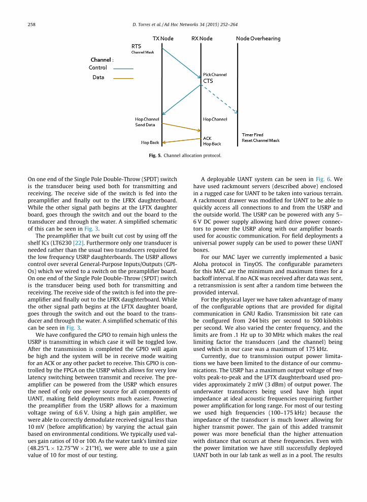
Fig. 5. Channel allocation protocol.
258 D. Torres et al. / Ad Hoc Networks 34 (2015) 252–264
On one end of the Single Pole Double-Throw (SPDT) switchis the transducer being used both for transmitting andreceiving. The receive side of the switch is fed into thepreamplifier and finally out to the LFRX daughterboard.While the other signal path begins at the LFTX daughterboard, goes through the switch and out the board to thetransducer and through the water. A simplified schematicof this can be seen in Fig. 3.
The preamplifier that we built cut cost by using off theshelf ICs (LT6230 [22]. Furthermore only one transducer isneeded rather than the usual two transducers required forthe low frequency USRP daughterboards. The USRP allowscontrol over several General-Purpose Inputs/Outputs (GPI-Os) which we wired to a switch on the preamplifier board.On one end of the Single Pole Double-Throw (SPDT) switchis the transducer being used both for transmitting andreceiving. The receive side of the switch is fed into the pre-amplifier and finally out to the LFRX daughterboard. Whilethe other signal path begins at the LFTX daughter board,goes through the switch and out the board to the trans-ducer and through the water. A simplified schematic of thiscan be seen in Fig. 3.
We have configured the GPIO to remain high unless theUSRP is transmitting in which case it will be toggled low.After the transmission is completed the GPIO will againbe high and the system will be in receive mode waitingfor an ACK or any other packet to receive. This GPIO is con-trolled by the FPGA on the USRP which allows for very lowlatency switching between transmit and receive. The pre-amplifier can be powered from the USRP which ensuresthe need of only one power source for all components ofUANT, making field deployments much easier. Poweringthe preamplifier from the USRP allows for a maximumvoltage swing of 6.6 V. Using a high gain amplifier, wewere able to correctly demodulate received signal less than10 mV (before amplification) by varying the actual gainbased on environmental conditions. We typically used val-ues gain ratios of 10 or 100. As the water tank’s limited size(48.25’’L � 12.75’’W � 21’’H), we were able to use a gainvalue of 10 for most of our testing.
A deployable UANT system can be seen in Fig. 6. Wehave used rackmount servers (described above) enclosedin a rugged case for UANT to be taken into various terrain.A rackmount drawer was modified for UANT to be able toquickly access all connections to and from the USRP andthe outside world. The USRP can be powered with any 5–6 V DC power supply allowing hard drive power connec-tors to power the USRP along with our amplifier boardsused for acoustic communication. For field deployments auniversal power supply can be used to power these UANTboxes.
For our MAC layer we currently implemented a basicAloha protocol in TinyOS. The configurable parametersfor this MAC are the minimum and maximum times for abackoff interval. If no ACK was received after data was sent,a retransmission is sent after a random time between theprovided interval.
For the physical layer we have taken advantage of manyof the configurable options that are provided for digitalcommunication in GNU Radio. Transmission bit rate canbe configured from 244 bits per second to 500 kilobitsper second. We also varied the center frequency, and thelimits are from .1 Hz up to 30 MHz which makes the reallimiting factor the transducers (and the channel) beingused which in our case was a maximum of 175 kHz.
Currently, due to transmission output power limita-tions we have been limited to the distance of our commu-nications. The USRP has a maximum output voltage of twovolts peak-to-peak and the LFTX daughterboard used pro-vides approximately 2 mW (3 dBm) of output power. Theunderwater transducers being used have high inputimpedance at ideal acoustic frequencies requiring furtherpower amplification for long range. For most of our testingwe used high frequencies (100–175 kHz) because theimpedance of the transducer is much lower allowing forhigher transmit power. The gain of this added transmitpower was more beneficial than the higher attenuationwith distance that occurs at these frequencies. Even withthe power limitation we have still successfully deployedUANT both in our lab tank as well as in a pool. The results

(a) Front view of UANT system (b) View inside drawer
Fig. 6. These two figures show a deployable UANT system (a) front view and (b) inside view of USRP, low frequency daughterboards and custompreamplifier and switch.
(a) FFT of tank setup. (b) FFT of larger pool.
Fig. 7. Frequency spectrum of tank (a) and pool (b). The two large noise sources (around 25 kHz in the tank, and 75 kHz in the pool) are the water pumps.
D. Torres et al. / Ad Hoc Networks 34 (2015) 252–264 259
to follow were taken from testing in the 55 gallon tanksetup (48.25’’L � 12.75’’W � 21’’H) we had in our lab.
6. Evaluation
The need to have a deployment time configurable sys-tem is realized with Fig. 7. Depending on the location theoptimal transmit center frequency can differ. The noisesource of the lab tank was primarily the filtration systemwhich was centered around 25 kHz. When we deployedUANT in the pool we found that the noise source was cen-tered closer to 75 kHz.
Although it might be expected that a controlled envi-ronment would produce better results than a real worldscenario this is not always the case. We found that our tank
(a) Original GMSK signal without multipath.
Fig. 8. These two figures show the effect of multipath on a GMSK signal. (a) Showsignal gets transmitted through a tank.
inside the lab was unfavorable for acoustic communica-tion. The reason for the poor results can be seen in Fig. 8,where the multipath of the signal is quite apparent. Themodulation for this test was not amplitude modulationbut rather GMSK. The reason there is such a variation inthe amplitude of the signal is multipath and inter-symbolinterference, which is a result of the slow speed of propa-gation. The best remedy for the multipath in our lab tankis to lower the transmission speed, this allows more sam-ples per symbol to be sent out to the USRP and receivedat the transducer.
One counterintuitive result we found in our lab tanktesting was the effect of our water filtration system. Gener-ally introducing a source of noise such as a filter that pro-duces bubbles, acoustic noise, and surface waves, willdegrade performance. Surprisingly this is not the case
(b) Effect of multipath on a GMSK signal.
s the original signal, without multipath. Figure (b) is the result if the same

1
1.5
2
2.5
3
3.5
4
4.5
5
0 500 1000 1500 2000 2500
MAC-Layer Transmissions
Per App Pkt
Backoff Interval(ms)
rate = 15 kb/srate = 10 kb/s
rate = 7.5 kb/s
Fig. 10. Netperf performance while varying minimum Aloha backoff timeat different transmission rates. Each data point collected over 300 s ofcommunication.
260 D. Torres et al. / Ad Hoc Networks 34 (2015) 252–264
and the explanation goes back to multipath. With thewater standing still a transducer that is attempting toreceive can be caught in a blind spot of destructive multi-path interference such that almost no signal is seen.Although typically these blind spots vary with time andspace due to moving reflective surfaces such as waves, ina controlled environment this is potentially not the case.Turning on the filter, although introducing noise, improvedsystem performance by receiving up to twice the amountof correct packets because of the now time varying blindspots.
6.1. Linux and TinyOS tools
6.1.1. PingUANT allows the ability to see application level perfor-
mance as a factor of the tunable parameters at the PHY andMAC layer. Fig. 9 shows how changing the minimum timeneeded to wait for an ACK before retransmission affect theLinux ping application. The backoff interval is set to 400 msfor this experiment and all other parameters are constant.If the minimum time to wait is too small there will bemany packet collisions mostly with the retransmission ofdata and the ACK packet itself, this leads to an increasednumber of retransmissions. On the other hand, if the min-imum time before retransmission is too large than if apacket is not received the transmitter is waiting needlesslylong to resend the data leading to low throughput and ahigh round trip time (RTT) even though very few retrans-missions are needed. Looking at this plot it is clear thattrade-offs can be achieved to either optimize for minimumtransmissions, quickest RTT, or a function of both.
6.1.2. NetperfAnother application that was tested in UANT was Net-
perf. Netperf establishes a connection between a clientand server and then sends TCP packets across the link. Notethat we did not need to make changes to standard TCPimplementation in our lab testing. However, default time-out values should be increased for a larger distancebetween nodes to avoid unnecessary timeouts. Fig. 10shows the results from the Netperf testing, where each
0
0.5
1
1.5
2
2.5
3
0 500 1000 1500 2000 0
0.5
1
1.5
2
Round Trip Time(s)
Avg Retransmission Per Pkt
Minimum Backoff Time(ms)
RTTRetransmissions per pkt
Fig. 9. Averaged over 50 pings for each data point with center frequencyat 100 kHz and transmit rate at 5 kb/s. All backoff intervals (max–min) setto 400 ms.
data point was collected over approximately a 300 s inter-val. We varied the transmission rate at both the physicallayer and MAC layer to see how that would affect perfor-mance. Regardless of the transmission rate if the Alohaminimum backoff interval was too low than it would causemany retransmissions. As the minimum backoff intervalincreased we found that the amount of retransmissionsdecreased since the nodes were not trying to retransmitto soon. As the transmission rate varied the amount ofretransmissions needed also varied. The fastest rate of15 kb/s lead to the least amount of retransmissions whilethe slowest rate that was tested (7.5 kb/s) resulted in thehighest amount of retransmissions. This result brings upanother advantage of having an easily reconfigurable sys-tem which allows to specify parameters at runtime.
6.1.3. A TinyOS applicationWe have also implemented an example TinyOS applica-
tion that fires a periodic timer and transmits its count overthe network to the other nodes. We were able to leave theapplication code unmodified while only changing the wir-ing configuration. The throughput of this application wasmuch higher than the Linux applications that we testedfor performance. One reason for this being that the over-head of a TCP/IP packet is much greater than the eightbit TinyOS message header that was used. Also there isadded latency for packets from Linux to get to TinyOS
Fig. 11. Test topology for channel allocation protocol.

0
0.1
0.2
0.3
0.4
0.5
0.6
0.7
0.8
0 10 20 30 40 50 60 70
Collision (%)
Packet Length (bytes)
One channelTwo channels
Three channels
Fig. 13. 60-Node network with different packet sizes.
0
0.05
0.1
0.15
0.2
0.25
0.3
0.35
0.4
0.45
0.5
0 50 100 150 200 250
Collision (%)
Network Size
One channelTwo channels
Four channels
Fig. 14. A fixed packet size with different network sizes.
D. Torres et al. / Ad Hoc Networks 34 (2015) 252–264 261
and then sent out, when compared to that of the applica-tion currently running in TOSSIM.
6.2. Channel allocation protocol
To evaluate our distributed channel allocation protocol,we deployed four nodes as shown in Fig. 11. In this topol-ogy, the network is fully connected and there are twosources and two sinks. This topology was chosen becausewe were limited to four nodes in our lab tank (i.e. severemultipath) and wanted to have simultaneous transmis-sions. Node one transmits to node three periodically whilenode two transmits to node four. A message is generatedusing the RadioCountToLeds TinyOS example application.This application periodically (every second by default)transmits a counter packet with different payload size toall of its neighbors.
6.2.1. Collision ratioA plot of the collisions using the channel hop protocol
can be seen in Fig. 12. We also plotted the collisions usinga shared channel and a random access MAC–ALOHA.Although this is not a completely fair comparison sinceproposed channel allocation protocol does use more band-width, it is plotted for a reference. One important observa-tion is that ALOHA without channel allocation increasesthe collision rate as the packet size increase. However,the channel allocation approach shows approximatelyfixed collision rate with the different packet size. The rea-son for this is that the collisions happen only on the controlchannel in proposed channel allocation protocol. Once thetransmitter and receiver hop to the reserved channel, theycan transmit data without collisions. This result leads tothe conclusion that if the nodes are able to access the con-trol channel sooner, collisions would be lesser. This can beseen by increasing control packet size, whose results omit-ted for sake of space limitations. Packet size: To verify thisgain in a large-scale, we deployed 60 nodes in the networkvia TOSSIM. As there were more nodes deployed, the datachannels need to be shared. This will increase collision rateas the channels were reused and packet size grew. Thiseffect can be seen in the simulation results in Fig. 13. Thisresult shows that with an increase in the number of chan-
0
0.1
0.2
0.3
0.4
0.5
0.6
0.7
0 20 40 60 80 100 120 140
Collision (%)
Packet Size (bytes)
Aloha MACChannel allocation
Fig. 12. Collision ratio as a function of packet size.
nels, the collision ratio is reduced. Furthermore since it is a60 node network and there are only four channels avail-able, some nodes have to share channels to transmit dataon and collisions may happen there. However, it is still sig-nificantly reduced from the case where all nodes share acommon channel.
6.2.2. Network sizeWe also simulated the channel allocation protocol
while varying the number of nodes in a network. In thissimulation, we fixed the packet size of 12-byte. As shownin Fig. 14, it shows the global tendency that collision ratesincrease as the number of nodes in the network increase.However, using multiple channels significantly reducethe collision rates in this scenario.
6.3. Time synchronization
To evaluate THSL’s performance, we were taken 20 Bea-cons using 10-s intervals on UANT. In addition, all our testswere run using the millisecond timer as opposed to themicrosecond timer. We had the opportunity to use themore precise microsecond timer; however, since our errorswere on the range on milliseconds, we did not see a point

Fig. 15. Number of beacons vs. skew.
262 D. Torres et al. / Ad Hoc Networks 34 (2015) 252–264
in placing additional stress on the system by using micro-second timers.
6.3.1. Number of beaconsShown in Fig. 15, the nodes share the same notion of
time after 7 beacons are sent the skew between nodes con-verges. We also noticed that using a software defined radiointroduces non-deterministic latency, so the accuracy ofthe skew and the offset of two nodes will increase with adedicated hardware solution even if fewer beacons areused.
6.3.2. Beacon intervalsFig. 16 indicates that when the beacon interval is not long
enough, the interference from multiple beacon messages(i.e., multipath) serve to disrupt reliable communicationbetween the beacon and the local node. Due to clock driftthat is apparent in all oscillators, even after nodes have beentime synchronized, they will eventually drift apart. Thisleads to the need for periodic re-synchronization.
6.3.3. Factors of non-linearityThere were a few possible reasons that affect the time
synchronization results. One was that our time-stampingwas done at a very high level in our system, at the applica-tion layer. This is a limitation with our system. Perhapswith a switch to a real-time pre-emptive kernel, the non-determinism can be reduced. However, even switching to
Fig. 16. Beacon intervals vs. skew.
a better kernel might not change the fact that there is someinherent non-determinism in our system. The packet willspend some non-deterministic time going from theapplication layer all the way down to the MAC layer, whereideally, is where we should time-stamp the packet. At thetime of the developing the system, there was no easy wayto have timestamps inserted into the data stream at thehardware level. The only way to insert the time-stamp atthe appropriate location was when forming the packet atthe higher layers. This restriction could be alleviated byadding custom blocks in the USRP FPGA offloading someof the software radio processing to hardware in exchangefor easy configurability. The USRP driver now offers anoption to timestamp received samples coming from theradio. This allows an easy way to get an precise timestampof a received packet. However, to inject a timestamp for atransmitted packet would still require modifications tothe USRP FPGA. By making improvements on the receiverside will help, but not eliminate the error introduced.
While very cheap oscillators tend to have a drift of 30–50 ppm (ppm), many underwater ranging solutions usemore precise clocks that are temperature compensatedthat can achieve accuracies of less than 1 ppm [23]. Twonodes with 50 ppm clocks can accumulate a maximumerror of 50 ms in approximately 8.3 min, while the clockused by Eustice et al. in [23] will accumulate 2 ms of errorin just under 14 h. Therefore depending on the nodes hard-ware, re-synchronization rates can vary dramatically butare still feasible with limited overhead.
In addition to an accurate clock source being used toreduce overhead of re-synchronization, time stamp infor-mation of beacons can be piggybacked in the header of adata transfer from the node with the reference clock. Inthis way when a node is receiving data it can also performthe linear regression and update the values of skew andoffset. Since phase two of TSHL requires one packet fromthe receiving node to be sent back to the transmitter, thisinformation can be appended to the acknowledgment thatis sent after the data transfer.
7. Conclusion
The challenges of the underwater acoustic channel aregreat, requiring the need for flexibility during system devel-opment. We have presented UANT as a complete end-to-end networking platform for underwater acousticcommunication. UANT is designed for field-deployment,geared toward fast prototyping and testing of PHY andMAC layer schemes. It is implemented using open sourcesoftware, facilitating further extension. We have demon-strated a Linux application running on UANT and evaluatedchannel allocation and time synchronization protocols onUANT.
Although we have applied and evaluated protocols andalgorithms along with implementing a few of our own,many are geared toward over the air or wired communica-tion. In the future we plan to implement recently proposedunderwater MAC and Routing protocols recently available.Allowing the protocols to be compared using UANT witheither a TinyOS or Linux application to benchmark perfor-mance will help distinguish strengths of each solution as

D. Torres et al. / Ad Hoc Networks 34 (2015) 252–264 263
compared with one another. We plan to further study theeffect of changing PHY and MAC layer parameters.
Acknowledgment
This work was supported in part by the US NationalScience Foundation under Grant No. 1205757.
References
[1] J. Preisig, Acoustic propagation considerations for underwateracoustic communications network development, SIGMOBILE Mob.Comput. Commun. Rev. 11 (4) (2007) 2–10.
[2] E. Sozer, M. Stojanovic, J. Proakis, Underwater acoustic networks,IEEE J. Ocean. Eng. 25 (1) (2000) 72–83.
[3] D. Torres, J. Friedman, T. Schmid, M.B. Srivastava, Software-definedunderwater acoustic networking platform, in: WUWNet, 2009.
[4] G.E. Santagati, T. Melodia, Sonar inside your body: prototypingultrasonic intra-body sensor networks, in: INFOCOM, Toronto,Canada, 2014.
[5] E. Jones, The application of software radio techniques to underwateracoustic communications, 2007, pp. 1–6.
[6] E.M. Sözer, M. Stojanovic, Reconfigurable acoustic modem forunderwater sensor networks, in: WUWNet, 2006.
[7] E. Blossom, Exploring GNU Radio. <http://www.gnu.org/software/gnuradio>.
[8] USRP Brochure, April 2009. <http://www.ettus.com/>.[9] P. Levis, S. Madden, J. Polastre, R. Szewczyk, K. Whitehouse, A. Woo,
D. Gay, J. Hill, E.B.M. Welsh, D. Culler, in: Ambient Intelligence,Springer, Berlin Heidelberg, 2005, pp. 115–148.
[10] K. Klues, G. Hackmann, O. Chipara, C. Lu, A component-basedarchitecture for power-efficient media access control in wirelesssensor networks, in: SenSys, 2007.
[11] P. Levis, N. Lee, M. Welsh, D. Culler, TOSSIM: accurate and scalablesimulation of entire TinyOS applications, in: SenSys, 2003.
[12] L. Girod, T. Stathopoulos, N. Ramanathan, J. Elson, D. Estrin, E.Osterweil, T. Schoellhammer, A system for simulation, emulation,and deployment of heterogeneous sensor networks, in: SenSys.
[13] G. Nychis, T. Hottelier, Z. Yang, S. Seshan, P. Steenkiste, EnablingMAC protocol implementations on software-defined radios, in:NSDI, 2009.
[14] L. Yang, Z. Zhang, W. Hou, B.Y. Zhao, H. Zheng, Papyrus: a softwareplatform for distributed dynamic spectrum sharing using SDRS,SIGCOMM Comput, Commun. Rev. 41 (1) (2011).
[15] N. Truong, Y.-J. Suh, C. Yu, Latency analysis in GNU radio/USRP-basedsoftware radio platforms, in: Military Communications Conference,MILCOM 2013 – 2013 IEEE, 2013.
[16] N. Truong, C. Yu, Investigating latency in GNU software radio withUSRP embedded series SDR platform, in: Eighth InternationalConference on Broadband and Wireless Computing,Communication and Applications (BWCCA), 2013, 2013.
[17] T. Schmid, O. Sekkat, M.B. Srivastava, An experimental study ofnetwork performance impact of increased latency in softwaredefined radios, in: WinTECH, 2007.
[18] K. Mandke, S.-H. Choi, G. Kim, R. Grant, R. Daniels, W. Kim, R. Heath,S. Nettles, Early results on hydra: a flexible mac/phy multihoptestbed, in: VTC, 2007.
[19] Wireshark network protocol analyzer. <http://www.wireshark.org/>.
[20] N. Baldo, P. Casari, P. Casciaro, M. Zorzi, Effective heuristics forflexible spectrum access in underwater acoustic networks, in:OCEANS 2008, 2008.
[21] A.A. Syed, J. Heidemann, Time synchronization for high latencyacoustic networks, in: Infocom, 2006.
[22] LT6230. <http://www.linear.com/product/LT6230>.[23] R. Eustice, L. Whitcomb, H. Singh, M. Grund, Recent advances in
synchronous-clock one-way-travel-time acoustic navigation, in:OCEANS.
Dustin Torres is a firmware engineer for IntelCorporation. He received his B.S. in computerengineering from University of California,Irvine in 2008 and his M.S in electrical engi-neering from University of California, LosAngeles in 2010. His research interestsinclude wireless sensor networks and under-water wireless communication.
Jonathan Friedman is the CEO and cofounderof GetScale, Inc., a company that developstechnologies to improve yield in Chinese fac-tories. He received his B.S. in computer engi-neering from the Georgia Institute ofTechnology (Georgia Tech) and his M.S. andPh.D. in electrical engineering from theUniversity of California, Los Angeles (UCLA).He is a visiting scholar in the Department ofNeuroscience at UCLA where his researchinterests include automated failure modeanalysis, process controls, and sensor systemsfor medical and industrial environments.
Thomas Schmid is an Adjunct Assistant Pro-fessor in the Electrical and Computer Engi-neering Department at the University of Utah,and the CEO and co-founder of RF Ranging,Inc.. His research interests are in wireless,embedded, and networked systems. He waspreviously a CI Fellows Post Doctoral Scholarat the University of Michigan, Ann Arbor. Hereceived his PhD in Electrical Engineeringfrom the University of California, Los Angelesin 2009, and was selected to receive the UCLAElecrical Engineering Department’s 2009–
2010 Outstanding Doctor of Philosophy Award for his dissertation. Hisresearch interests involve the hardware-software boundary and itsimpact on energy consumption, including software radios, large scale
sensing system architectures, and networking, with a focus on wirelessembedded systems.Mani B. Srivastava (Ph.D. 1992, Berkeley is onthe faculty at UCLA where he is associatedwith the EE Department with a jointappointment in the CS Department. Hisresearch is broadly in the area of networkedhuman-cyber-physical systems, and spansproblems across the entire spectrum ofapplications, architectures, algorithms, andtechnologies. His current interests includeissues of energy efficiency, privacy & security,data quality, and variability in the context ofsystems and applications for mHealth andsustainable buildings. He is a Fellow of theIEEE.

264 D. Torres et al. / Ad Hoc Networks 34 (2015) 252–264
YoungTae Noh is a Software Engineer at CiscoSystems, Inc. Prior to joining Cisco Systems, hereceived his B.S. in computer science fromChosun University in 2005, an M.S. degree inInformation and Communication fromGwangju Institute of Science Technology(GIST) in 2007, and a Ph.D. in computer sci-ence at University of California, Los Angeles(UCLA) in 2012. His research areas includedata center networking, wireless networking,future Internet, and mobile/pervasive com-puting.
Mario Gerla is a Professor in the ComputerScience at UCLA. He holds an Engineeringdegree from Politecnico di Milano, Italy andthe Ph.D. degree from UCLA. He became IEEEFellow in 2002. At UCLA, he was part of theteam that developed the early ARPANET pro-tocols under the guidance of Prof. LeonardKleinrock. At Network Analysis Corporation,New York, from 1973 to 1976, he helpedtransfer ARPANET technology to Governmentand Commercial Networks. He joined theUCLA Faculty in 1976. At UCLA he has
designed and implemented network protocols including ad hoc wirelessclustering, multicast (ODMRP and CodeCast) and Internet transport (TCPWestwood). He has lead the $12 M, 6 year ONR MINUTEMAN project,
designing the next generation scalable airborne Internet for tactical andhomeland defense scenarios. He is now leading two advanced wirelessnetwork projects under ARMY and IBM funding. His team is developing aVehicular Testbed for safe navigation, urban sensing and intelligenttransport. A parallel research activity explores personal communicationsfor cooperative, networked medical monitoring (see www.cs.ucla.edu/NRL for recent publications).