ad-a257 225
TRANSCRIPT

AD-A257 225CMU/SEI-92-SR-9
The Domain-SpecificSoftware Architecture Program
LTC Erik Mettalaand Marc H. Graham, eds.
June 1992
LX
x7
92-28199 K

Special ReportCMU/SEI-92-SR-9
June 1992
The Domain-Specific
Software Architecture Program
LTC Erik MettalaDARPA SISTO
Marc H. GrahamTechnology Division, Special Projects
Approved for public release.Distribution unlimited.
Software Engineering InstituteCarnegie " U^"" t
Pittsburgh, Pennsylvania 15213

This technical report was prepared for the
SEI Joint Program OfficeESD/AVSHanscom AFB, MA 01731
The ideas and findings in this report should not be construed as an officialDoD position. It is published in the interest of scientific and technicalinformation exchange.
RevIew and Approval
This report has been reviewed and is approved for publication.
FOR THE COMMANDER
John S. Herman, Capt, USAFJSEl Joint Program Office
The Software Engineering Institute is sponsored by the U.S. Department of Defense.This report was funded by the U.S. Department of Defense.
Copyright 0 1992 by Carnegie Mellon University
This document is available through the Defense Technical Information Center. DTIC provides access to and transfer ofscientific and technical information for DoD personnel, DoD contrac'ors and potential oontractors, and other U.S. Governmentagency personnel and their contractors. To obtain a copy, please contact DTIC directly: Defense Technical InformationCenter, Ann: FDRA, Cameron Station, Alexandria, VA 223C4-6145.Copies of this document are also available througt, the National Technical Information Service. For information on ordering,please contact NTIS directly: National Technical Information Service, U.S. Department of Commerce, Springfield. VA 22161.
Copies of this document are also available from Research Access, Inc., 30111 Forbes Avenue, Su:,a 302, Pittsburgh, PA 15213.
(.Iae of any tr••* narks ir this repolt is not intended in any way to infringe on the rights of the trademark holder.

Table of Contents
The Domain Specific Software Architecture ProgramLtC Erik Mettala and Marc H. Graham
1 Introduction 1
2 Structure of the DSSA Program 22.1 Overview of Technical Issues Raised by DSSA 3
2.1.1 Software Architectures 32.1.2 Domain-specific Software Development 42.1.3 Process Issues 52.1.4 Development Environments 5
3 Role of the SEI 6
References 6
An Avionics Domain-Specific Software ArchitectureLou Coglianese, Mark Goodwin, Roy Smith, Will Tracz, Don Batory,Kirstie Bellman, David Gries, David McAllester, Rick Selby, and Richard Taylor
1 Introduction 101.1 The Avionics Problem Domain 101.2 DSSA-ADAGE Research Objectives 111.3 DSSA-ADAGE Approach 111.4 Progress to Date 13
References 13
Domain-Specific Software Architectures: Command and ControlChristine Braun, William Hatch, Theodore Ruegsegger, Bob Balzer,Martin Feather, Neil Goldman, and Dave Wile
1 The DSSA Concept 15
2 Why Command and Control? 16
3 GTE's Approach 17
4 Application Generation 184.1 The Technology 184.2 1 ne AP5 Approach 19
5 C2 Message Handling 20
6 Automating C2 Message Handling Using AP5 226.1 Specifying Message Formats 236.2 Specifying Datasets 246.3 Specifying Database Transactions 24
CMU/SEI-92-SR-9

7 Implications 25
8 Acknowledgments 25
References 25
Domain-Specific Software Architectures:Distributec Intelligent Control and Communication
Frederick Hayes-Roth, Lee D. Erman, Allan Terry, and Barbara Hayes-Roth1 Introduction 282 The DICAM Framework 29
3 Controllers In Application:Automated & Mixed Inltiative33
3.1 Automated Control 343.2 .Mixed Initiative Control 35
4 The Development Methodology 364.1 Development Workspace 374.2 Development Methods and Tools 38
5 Development Support Environment 406 Status and Plans 41
6.1 A Partial Development Scenario 457 Mappings Between KE And SE In DICAM 53
8 Related Research 549 Conclusions 55References 55
Domain-Specific Software Architectures forIntelligent Guidance, Navigation, & Control
Ashok Agrawala, James Krause, and Stephen Vestal
1 Introduction 631.1 Formal Models 641.2 Multiple Views 651.3 Open, Layered Architecture 65
2 Architecture Views 663 Architecture Layers 69
3.1 Guic;a.ice, Nav ControlH 693.2 Kernel, Reliability Events 703.3 Domain Extension 71
CMU/SEI-92-SR-9
4 Conclusion 72
Domain-Specific Software Architectures for Hybrid ControlRichard Platek and James H. Taylor
1 The Domain 73
2 The Approach 74
3 Conclusion 75
References 75
Application of ProtoTech Technology to the DSSA ProgramFrank C. Belz, David C. Luckham, and James M. Purtilo
1 Introduction 77
2 Our Research Hypothesis 78
3 The Enabling Technology 79
4 Melding Research and Technology Transfer 83
References 84
CMU/SEI-92-SR-9 iii

iv CMtu/SEI-92-SR-9

List of Figures
The Domain Specific Software Architecture ProgramFigure 1-1 Hitting the Brick Wall! 2
An Avionics Domain-Specific Software ArchitectureFigure 1-1 Typical Pilot in the Loop Navigation, Guidance,
and Flight Director 11
Figure 1-2 DSSA-ADAGE Approach 12
Domain-Specific Software Architectures:Command and Control
Figure 3-1 GTE's DSSA Approach 17
Figure 4-1 DSSA Application Generation Activity Flow 20
Figure 5-1 C2 System Operations 21
Figure 5-2 Example Message Line Description 22
Figure 5-3 Example Formatted Message 23
Domain-Specific Software Architectures:Distributed Intelligent Control and Communication
Figure 1-1 Focus Elements of Our DICAM-DSSA Research 28Figure 2-1 The DICAM Reference Architecture 30Figure 2-2 Individual Controller Reference Architecture:
Domain Control & Meta-Control 32Figure 3-1 Controller Interactions 34Figure 3-2 Controller Architecture Augmented
for Human Component Interface 35Figure 4-1 The Development Workspace 36Table 1 Aspects of the Development Methodology 39Figure 5-1 The Application Development Support Environment (ADSE) 40Figure 6-1 Specializing the Generic DICAM Controller Structure
for a Particular Howitzer 42Figure 6-2 Informal Task Application Model for a Portion
of the Howitzer Example 43Figure 6-3 Building the Application Model 44Figure 6-4 Partial Layout of the Repository 44Figure 6-5 Browsing RSOP Requirements 46Figure 6-6 Evaluating a Requirements Group 46Figure 6-7 Checking the To-Do List 47Figure 6-8 Getting More Details on the Task 47Figure 6-9 Getting Advice on How to Complete the Task 48Figure 6-10 Script for Fix Shows Existing Processor 49
CMU/SEI-92-SR-9

Figure 6-11 KBDA Conducts a Dialog with the User 49Figure 6-12 User Selects from the Choices Offered 50Figure 6-13 Script Provides Some Design Cleanup Ac, ns 51Figure 6-14 Results of a KBDA Reflected In the To-Do List 51Figure 6-15 User Queries Repository for Possible Modules 52Figure 6-16 Summary of the Matches Found 52Figure 6-17 User Browses RSOP Requirements 53
Domain-Specific Software Architectures forIntelligent Guidance, Navigation, & Control 63
Figure 2-1 Example Architecture Views 66Figure 2-2 Architecture Views 68Figure 3-1 Architecture Layers 69Figure 3-2 ControlH Specification and Interface 70
vi CMU/SEI-92-SR-9

The Domain-Specific Software Architecture Program
LTC Erik MettalaDARPA SISTO
3701 N. Fairfax DriveArlington, VA 22203-1714
Marc H. GrahamSoftware Engineering Institute
Carnegie Mellon UniversityPittsburgh, PA 15213
Abstract: The DARPA Domain Specific Software Architecture Program(DSSA) is a five-year effort that has been active since July 1991. Thisdocument contains an overview of the work being done in the program as ofJuly 1992.
Software architectures serve as frameworks for software reuse. Domain-specific software architectures also serve as a common language in whichdomain engineers can discuss, understand and teach the principles of theircraft.
There are six independent projects within the DSSA program. Four of theseprojects are working in specific, militarily-significant domains. Those domainsare Avionics Navigation, Guidance and Flight Director for Helicopters;Command and Control; Distributed Intelligent Control and Management forVehicle Management; Intelligent Guidance, Navigation and Control forMissiles. In addition, there are two projects working on underlying supporttechnology: Hybrid (discrete and continuous, non-linear) Control andPrototyping Technology.
This report contains brief descriptions from each project and an overview.
Introduction
System engineers design systems out of various materials: metals, hydraulics, electronics andsoftware. When working with material other than software, they use tools and componentsspecific to the task z' hand. Those artifacts are the packaged expertise of a host of other en-gineering disciplines. The software in the system, on the other hand, is hand crafted by thesoftware engineers, uniquely for the system being built, but out of the same low-level, generalpurpose building blocks for every system. The work being done in the DSSA program in do-main-specific software development is meant to transform the relation of system and softwareengineers into one in which software engineers create building blocks and construction toolsout of and with which system engineers create software subsystems.
In contrast to the DSSA program's vision of software development, Figure 1-1 illustrates the re-lation of system and software design today. The figure is drawn from the perspective of a con-trols engineer solving a problem using an iterative process of simulation and analysis. The
CMU/SEI-92-SR-9 1

I ~math AnalysislP. Math ModelJ!Smudlatio Simulation
Figure 1-1 Hitting the Brick Wall!solution takes the torm ot an "algorithm" that is well-cetined in control theory and is known tobe correct (within the accuracy of the analytic and simulation models). Before the algorithmcan be implemented, it hits the "brick wall" called the Software Specification. Behind the wall,software engineers receive an unwieldy translation of the algoritV'm that has lost definitior andquite possibly accuracy. The translation from the language of control theory to the language ofsoftware cannot add anything; it can only introduce errors. domain-specific software develop-ment tears down brick walls like these by applying the application engineer's problem-orientedlanguage more directly to the task of software construction.
Figure 1-1 should not imply that the DSSA program is concerned only with control applicationsor only front-end issues such as algorithm design. The individual projects within DSSA covera wide range of software development activities, from concept formulation and prototyping,software process design and measurement through software development, documentationand maintenance. No single project tackles all these problems, but the program as a whole isdistinguished by its interest in the entire problem of software development.
2 Structure of the DSSA ProgramThe DSSA program is a five-year program that has been active since July 1991. There are sixindependent projects in the program. Each project is led by an industrial research lab, eachhas at least one academic partner, and each works with a military lab in the context of a spe-cific research product. Four of the projects are applying themselves to specific military do-mains. They are:
* Avionics Navigation, Guidance and Flight DirectorPrincipal Contractor-. IBM Federal Sector DivisionPrincipal Investigators: L(cu Coglianese, Mark Goodwin, Will Tracz.Academic and Industrial Partners: Don Batory, University of Texas; Kirstie Bellman,Aerospace Corporation; David Gries, Cornell; David McAllester, MIT; Rick Selby,UC at Irvine; Dick Taylor, UC at IrvineMilitary Lab Partner. Wright Aeronautical Laboratories.
2 CMU/SEI-92-S--9"
"* Command and ControlPrincipal Contractor: GTr- Federal SyztemsPrincipal Investigators: C ;stine Braun; William Hatch; Theodore RuegseggcrAcademic Partners: Bob L -.zer, Martin Feather, Neil Goidman, Dave Wile,USC/Information Scierces Institute; Bob Might, George Mason UniversityMilitary Lab Partner: US Army Communications and Electronics Command(CECOM).
" Distributed Intelligent Control and Management (PICAM) for VehicleManagementPrincipal C.cwtractor. Teknowledge Federal SystemsPrincipal Investigators: Frederick Hayes-Roth, Lee Erman, Allan TerryAcademic Partners: Farbara Hayes-Roth, Gene Franklin, Stanford UniversityMilitary Lab Partner. US Army Armament Research. Development and EngineeringCenter (ARDEC).
" Inteot 7gent Guidance, Navigation and ControlPrincipal Contractor: Honeywell Systems and Research CenterPrincipal Investigators: Mike Jackson, Steve Vesta;Academic Partner: Ashok P grawal, U. of ,.'arylandMilitary Lab Partner: Office of Naval Research (0,NR).
Two of the projects investigate enabling technologies under'ying domain-specific softwareconstruction:
" Hybrid ControlPrincipal Contractor: ORA CorporationPrincipal Investigators: Richard Platek, James H. TaylorAcademic Partners: Anil Nerode, John Guckenheimer, CornellMilitary Lab Partner: ARDEC.
"* Prototyplng TechnologyPrincipal Contractor: TRWPrincipal Investigator: Frank BelzAcademic Partner: David Luckham, StanfordMilitary Lab Partner: ONR.
2.1 Overview of Technical Issues Raised by DSSA
2.1.1 Software ArchitecturesWithin the DSSA program there are three distinct approaches to architectures. The IBM andGTE projects are based on domain modelling approaches exemplified by the work of Prieto-Diaz and Cohen, and are collected in a recent IEEE tutorial [Prieto-Diaz 87], [Kang 90], [Pri-eto-Diaz 91]. This approach identifies the critical aspects (objects, operations and relation-ships) in a domain or class of problems as the experts in the domain perceive them. Theseaspects are represented in some way as a domain model.1 The model is independent of anySnplementation. A software architecture is drawn from the model. Where the m',del describes
1. Domain modelling is a rich and evolving field to which the DSSA researchers are making varied contributions.Thereader should not assume that there is or will be a single DSSA domain modeling technology.
CMU/SEI-92-SR,9 3

a family of problems, the architecture describes a family of solutions. The architecture con-strains possible solutions by setting, at various levels of abstraction and detail, a collection ofcomponents and component interfaces.
Software architectures serve as frameworks for software reuse. As explained below, domain-specific software development encompasses generative as well as reuse or compositionaltechniques. Domain-specific software architectures also serve as a common language inwhich domain engineers can discuss, understand and teach the principles of their craft. Par-ticipation of the George Mason Center for C31 in the GTE project puts it in a favorable positionfor influencing the consensus building process. Partnership with military laboratories is a wayin which each of the projects interacts with its user community.
The Teknowledge project is based in part on a particular software architecture, or "architecturalstyle", associated with the work of NIST in robotic control [Albus 89]. That architecture pro-poses a multi-level hierarchy of controllers. The lowest level deals with control of individualservomechanisms; the highest level controls the interaction of groups of groups of controllers.Each controller has access to a "conceptually global" information base and world model. Tothis structure, Teknowledge adds a two-level architecture for each controller. A "domain con-troller" (DC) has responsibility for determining plans of action without regard for time con-straints. A "meta-controller" directs the execution of the planned actions with the goal ofmaximizing the use of scarce resources, particularly time constraints.
The Honeywell and ORA projects' concept of a software architecture is quite different. Honey-well proposes multiple formal engineering models for the domain of guidance, navigation andcontrol. The models include differential and difference equations for the description of controllaws, scheduling theory and optimization for schedulability analysis and Markov processes forthe determination of reliability. Software architectures are derived from these formal models.ORA is developing the mathematical field of hybrid (both discrete and continuous) control the-ory as the basis of a software architecture.
2.1.2 Domain-specific Software DevelopmentVarious mechanisms of domain-specific software development are under investigation withinthe projects. Compositional mechanisms facilitate reuse of existing artifacts, including soft-ware. Generative mechanisms are used when needed components are not available.1 Con-straint-based reasoning systems and module interconnection languages are critical underlyingtechnologies for software composition. Prototyping technologies underlie generation. TheTRW project serves as a technology conduit from the prototyping community into the DSSAprogram.
1. Programming in third generation programming languages (e.g., Ada) is a form of software generation. Domain-specific software development will not eliminate the need for such programming any more than third generationlanguages eliminated the need for assembler programming. The aim is to drastically reduce the amount of suchprogramming.
4 CMU/SEI-92-SR-9

Parameterized mechanisms are both .' mpcitional and generative. In using a parameterized
software development mechanism, an engineer specifies the functionality, behavior and con-
straints on a system component by filling out a form. The recorded values drive the mechanism
in the creation of the specified component out of pre-existing software and software templates.
(See Batory's work in database management system generation [Batory 88].)
Parameter driven application generators are useful for domains whose variability is well under-
stood in advance. For domains whose variability is broader or less well understood, other
mechanisms are needed. These mechanisms may be domain independent or domain-spe-
cific.
The Honeywell and ORA projects are developing mechanisms specific to the domain of control
systems. Currently ORA seeks to improve the state of the art in control law generation, stress-
ing the development of non-linear control algorithms based on dynamical system simulation.
Honeywell is designing a language for the specification and analysis of control a!gorithms. The
software generated to implement those algorithms is analyzed for schedulability, bound to
hardware platforms, and composed with portions of a collection of runtime support modules toproduce a given application.
As an early test, the GTE project applied some of its ideas to message handling in commandand control systems. The project created a domain-specific message handling language fordescribing the format, validation, and processing of C3 messages. A program generator trans-lates this DSSA language into a domain independent specification language, AP5 [Cohen 87],which is then translated into the target programming language. Initial results show a 100-fold
decrease in the amount of code needed to format, validate and process messages used in the
Army Tactical Command and Control System (ATCCS).
2.1.3 Process Issues
Domain-specific software development requires new processes to regulate the engineering
activities comprising system design. IBM and GTE are developing descriptions of processesbased on domain modelling paradigms. Both projects include measurement based processimprovement programs. They and others are investigating the use of process enactment lan-
guages. Teknowledge is developing a mixed-initiative process language, supporting interac-tion among the application developer, core development environment, and the tools looselycoupled to that environment.
Honeywell has proposed a process that organizes the efforts of control engineers, system
engineers, reliability engineers, safety engineers, etc., as well as software engineers [Krause91]. Control software development is an interdisciplinary activity that requires an integratedproduct development process, sometimes called "concurrent engineering".
2.1.4 Development Environments
Although tools and environments are an important product, the DSSA program is not an envi-ronment program. Thus, the program looks to import much of the needed technology from oth-
CMU/SEI-92-SR-9 5

ers. In particular, it looks to STARS for reusability library frameworks; to Arcadia for various
features such as Chiron, Amadeus, APPL/A and possibly others; and to the PROTOTECH
community for prototyping and module interconnection. The program has formed a working
group on environment integration, infrastructure and tooling issues to more efficiently share
knowledge and expertise.
3 Role of the SEI
The Software Engineering Institute plays an important supporting role in the DSSA program.
The SEI is committed to being an integral component of DARPA and to accelerating the tran-
sition of technology from the research community into the DoD and the defense industry. The
SEI has developed expertise in the nature of technology transition and is able to assist the
DSSA projects and their military partners in planning for the transition of DSSA products into
the laboratories and eventually into the field. Even though the DSSA program is not yet
through the first year of its life, this planning has already begun.
Other opportunities for SEI support to DSSA are being explored. Some of these, at the time
this is being written, are as follows:
" Process Description. As mentioned earlier, DSSA contractors have an interest insoftware process description. The SEI currently has a project that, in cooperationwith the STARS program, is involved in describing software processes. STARS hasa strong interest in the kinds of processes DSSA requires. Thus, the SEI can play arole in the cross-fertilization of two DARPA programs.
" Software Development Environments. The SEI's Environment Focus Area hasexpertise and interest in tool integration and environment frameworks. The DSSAprogram's work in environments represents an opportunity for mutual benefit. Someearly meetings designed to realize this benefit will have been held by the time this ispublished.
References[Albus 89] Albus, James; McCain, H.G.; Lumia, R. NSA/NBS Standard Reference
Model For Telerobot Control System Architecture (NASREM). TechnicalReport 1235, National Bureau of Standards, 1989.
[Batory 88] Batory, Don S. Building Blocks of Database Management Systems.Technical Report TR-87-23, University of Texas at Austin, February 1988.
[Cohen 87] Cohen, Donald. "Automatic Compilation of Logical Specifications IntoEfficient Programs". Proceedings of the 5th National Conference on ArtificialIntelligence. ACM Press, August 1987: 20-25.
[Kang 90] Kang, K.C; Cohen, S.C: Jess, J.A; Novak, W.E; Peterson, A.S. Feature-
Oriented Domain Analysis (FODA) Feasibility Study. (CMU/SEI-90-TR-21,ADA235785). Software Engineering Institute, November 1990.
6 CMU/SEI-92-SR-9

[Krause 91) Krause, Jim; Vestal, Steve. 'Thoughts on a DSSA-Based AGN&C
Development Process". Personal correspondence, September 1991.
[Prieto-Diaz 87] Prieto-Diaz, Ruben. "Domain Analysis for Reusability". Proceedings of
COMPSAC 87. ACM Press, 1987.
[Prieto-Diaz 91] Prieto-Diaz, Ruben; Arrango, Guillermo.Domain Analysis and Software
Systems Modelling. IEEE Computer Society Press, 1991.
CMU/SEI-92-SR-9 7

8 CMU/SEI-92-SR-9

An Avionics Domain-Specific Software Architecture
Lou Coglianese, Mark Goodwin, Roy Smith, and Will TraczIBM Federal Systems Company
MD 0210Owego, NY 13827
[email protected]@OWGVMO.VNETIBM.COM
Don BatoryUniversity of Texas at Austin
Computer Science DepartmentTaylor 2.124
Austin, TX [email protected]
Kirstie BellmanCSTS
The Aerospace Corp.PO Box 92957
Los Angeles, CA [email protected]
David GriesComputer Science Department
Cornell UniversityIthaca, NY 14853
David McAllesterDepartment of Electrical Engineering and Computer Science
MITCambridge, MA
Rick Selby and Richard TaylorDepartment of Computer Science
University of California at IrviceIrvine, CA 92717
[email protected]@ics.uci.edu
Abstract: The DSSA-ADAGE (Domain-Specific Software Architecture-Avionics Domain Application Generation Environment) Project is part ofDARPA's Domain-Specific Software Architecture Program. IBM, in cooperationwith researchers at the Aerospace Corporation, MIT, Cornell, the University ofTexas at Austin, and the University of California at Irvine, is striving to create aworkstation-based environment to support the development, maintenance, andupgrade of avionics systems through the reuse of large portions of well-designed and well-documented software. This paper qualifies the scope of theADAGE Project within the avionics domain and describes the project'sresearch goals and approach. The paper concludes with a summary ofprogress made to date in defining an avionics architecture and domain model,an avionics domain-specific vocabulary, and domain-engineering andarchitecture-based development processes.1
1. This research was partially sponsored by DARPA and the Avionics Logistics Branch, Wright Laboratory, Wright-Patterson AFB, OH, under contract F33615-91 -C-1 788.
CMU/SEI-92-SR-9 9

1 Introduction
DSSA-ADAGE is a joint industry/university research effort to apply leading edge basicresearch to the avionics domain. DSSA-ADAGE is an extension to the large-scale avionicsreuse effort [Coglianese 87] (i.e., RASP (Reusable Avionics Software Project [Bunts 90]) andsoftware composition [Tracz 91 a] research at the Owego, NY Laboratory of IBM-Federal Sec-tor Division (FSD), where software developers have created avionics software for over adozen fixed-wing aircraft and rotorcraft).
The avionics application domain encompasses the use of electronics to provide operator sup-port for performing an assigned task with an aircraft or space vehicle.1 Typically, for each newavionics system, systems developers create or re-create the software that provides the oper-ator interface and integrates the electronics rather than reuse existing software. The goal ofthe DSSA-ADAGE is to provide system develope s with the necessary environment to locate,adapt, compose, generate, integrate, and evaluate avionics applications within the subdo-mains of Navigation, Guidance, and Flight Director by analyzing a problem domain and creat-ing/refining a set of standardized solutions within it.
1.1 The Avionics Problem Domain
An avionics system integrates the complex components of crew, airframe, powerplants, sen-sors, and specialized subsystems into an intelligent airborne system for achieving specific mis-sion objectives within time and space constraints. Within the overall DoD mission, theseobjectivE can include delivery of ordnance on designated targets within a specified time 'Win-dow", recording of electronic, geographic and other remotely detectable information over aselected area within a specified time frame, or transport of personnel and material betweenlocations on a specified schedule. While executing these missions the airborne system mayneed to meet other constraints, such as minimizing use of human resources, avoidance ofdetection by surface/air/space based sensor systems, rendezvous and cooperation with otherfriendly mission elements, or flight into adverse weather, at night, without external navigationaids.
The core requirements of most advanced avionics systems include the capability to navigate,provide guidance, and provide flight direction (see Figure 1-1). Navigation is the ability to esti-mate the aircraft state relative to one or more reference frames. Guidance contains algorithmswhich analyze temporal and spatial mission objectives to produce desired lateral, vertical,and/or speed profiles based on aircraft performance characteristics and selected optimizationcriteria. Flight direction accepts the error signals and recommends control inputs to the crew(or aircraft automatic flight control system for coupled flight) which will null out the error signalsthus locating the aircraft on the desired path.
1. Portions of this paper are based on "DSSA Case study: Navigation, Guidance, and Flight Director Design andDevelopment", by Lou Coglianese, Roy Smith, and Will Tracz, which appeared in the proceedings of the 1992IEEE Symposium on Computer-Aided Control System Design (CACSD'92), March 1992.
10 CMU/SEI-92-SR-9
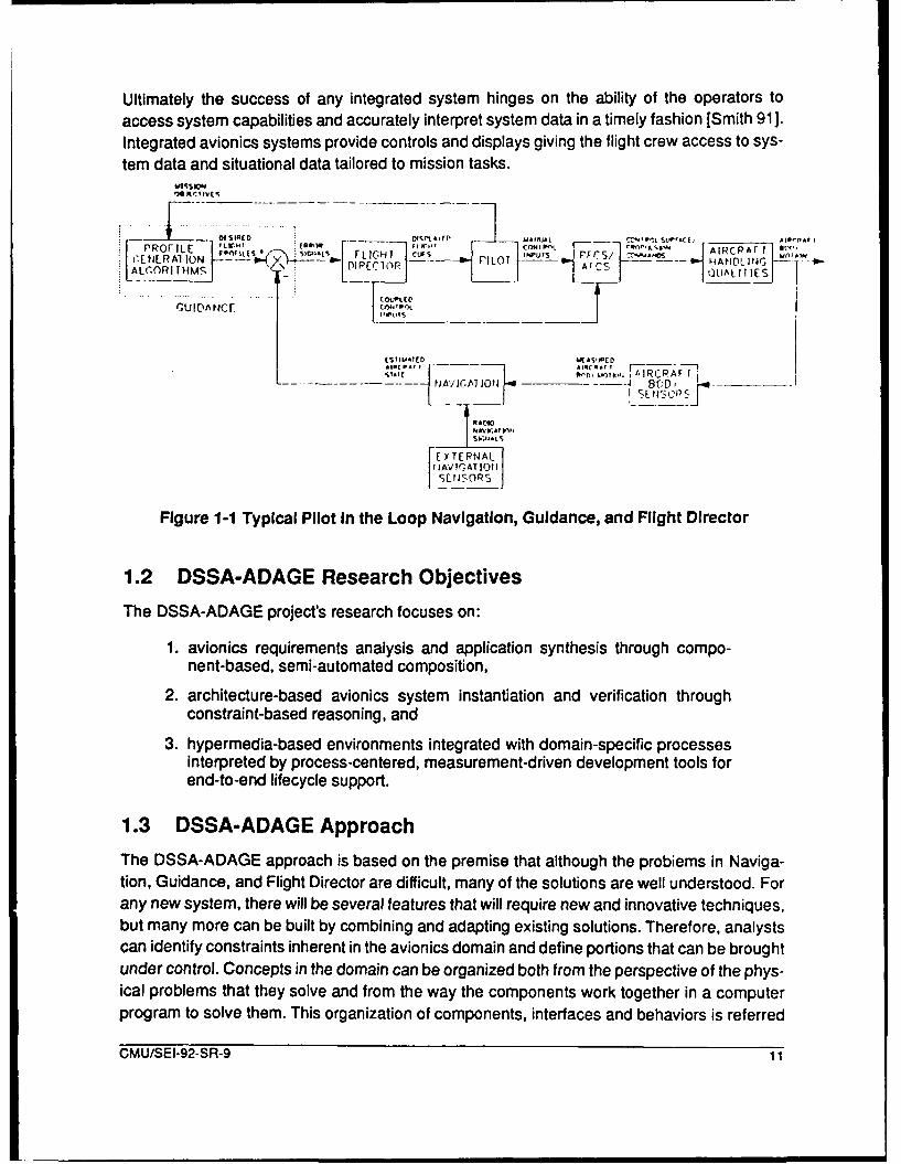
Ultimately the success of any integrated system hinges on the ability of the operators to
access system capabilities and accurately interpret system data in a timely fashion [Smith 91 ].
Integrated avionics systems provide controls and displays giving the flight crew access to sys-
tem data and situational data tailored to mission tasks.
INSIRCD rDISPI111tf .- I", Lirf :I- PartPRO lIE S n. r AIRCPAF T
MPiiOt -IIGUYS [ EL5H _-.Nos HANDL INERAL ION -- VPIHlO ILTAr OLUAL II JES
GUIDAN. 01%
.STIT ED IASJPED_____.,, _
T I( ý"lu~A.i I RCPAFt)AV_____A_ BC48(D, -___-_
r -- •.LJvr.Ir Iv,
SE tAto
MA A "PI
FE..TEPNAL( II AI CAT 1011
SENSORSOP
Figure 1-1 Typical Pilot In the Loop Navigation, Guidance, and Flight Director
1.2 DSSA-ADAGE Research Objectives
The DSSA-ADAGE project's research focuses on:
1. avionics requirements analysis and application synthesis through compo-nent-based, semi-automated composition,
2. architecture-based avionics system instantiation and verification throughconstraint-based reasoning, and
3. hypermedia-based environments integrated with domain-specific processesinterpreted by process-centered, measurement-driven development tools forend-to-end lifecycle support.
1.3 DSSA-ADAGE Approach
The DSSA-ADAGE approach is based on the premise that although the probiems in Naviga-
tion, Guidance, and Flight Director are difficult, many of the solutions are well understood. Forany new system, there will be several features that will require new and innovative techniques,but many more can be built by combining and adapting existing solutions. Therefore, analystscan identify constraints inherent in the avionics domain and define portions that can be broughtunder control. Concepts in the domain can be organized both from the perspective of the phys-ical problems that they solve and from the way the components work together in a computerprogram to solve them. This organization of components, interfaces and behaviors is referred
CMU/SEI-92-SR-9 11

to as a Domain-Specific Software Architecture (DSSA). A DSSA not only provides a frame-work for reusable software components, but it also organizes design rationale and structuresadaptability.
The DSSA-ADAGE team is building an architecture and a hypermedia-based environmentthat assists analysts and software developers in automating avionics development. TheADAGE environment, depicted in Figure 1-2, relies on:
"* hypermedia representation of design record knowledge to facilitate softwareunderstanding,
" wrapping components with pedigree [Bellman 90] information to be used in analysis,modelling, development, and integration,
"* constraint-based reasoning tools to reduce the user's adaptation and selectionworkload, software composition technology (Tracz 91 b] to construct analyses,models, simulations and real-time software for embedded systems by combiningcomponents and user selections with implementation models, and
"* a formal representation ([Osterweil 87], [Sutton 90]) of iterative spiral developmentprocess models and process measurement tools [Selby 91] to guide user actions.
DSSA-ADAGE : Avionics Domain Applicaicon Generation Environment
SP-TIO-Ce$SeS t
L Domi.n Enginewmg Conceptual Desgn Compooen4-Based Dveleopmnl
Specty'-F S" W Ah'*ll _nl _-_Sft'• _--s--- Tod -
[ • •"!UC;%9-*Ied4- " /i/ Eopoty Von lo
,-, .t-9~iled Tt ~mh ,
sinGreil G.nrt
Ex.eubsI T--- Jr " '
AEvu - S- Aly
_Im v •su rI Inm \h
CUsmers H Wor -dgh Fid ity Suiai•ai
Anayst E tlil Rllier 4 All IF Earl VanldaPelownnc
Developers X "
UnqYrocesscm *-Tirni
/ Otisut;W d TotOenchParalle 1asog Model's
Evaluate1 -
12 C U/SFight SystR -
K Feedac Comprat,vq naly*e rcssGadn~~easu~~emontsP Poces ', ovrne,
Art~ctwq tkrll Cmonenflft All elementsWel WtUnderstood 9 Un-de,slood NtWelt Under slood o L
Moderately Varibl-) Haghty Va'.9t4e Now, Functio Perlomm'c
FIgure 1-2 DSSA-ADAGE Approach
12 CMU/SEI-92-SR-9

1.4 Progress to Date
The DSSA-ADAGE project came under contract in September of 1991. Most of the effort spent
during the first quarter focused on gathering momentum. Team members working with domain
experts defined and applied a domain engineering and component-based application genera-
tion process that afforded academic team members the opportunity to understand avionics
domain terminology and concepts.
Lou Coglianese provided a preliminary avionics architecture definition of Navigation, Guid-
ance and Flight Director at the first team meeting on September 26-27. Navigation analysis
focused on models of data sources, the aircraft state vector, earth and atmospheric models,and relational coordinate models. The initial avionics domain knowledge engineering process
results were sent out for review by team members and external sources. As a result, Sholom
Cohen, at SEI, recognized the preliminary architecture to be similar to that used on the CAMP
(Common Ada Missile Package) System (with the exclusion of a pilot in the loop).
Don Batc, y has created a preliminary version of domain model (i.e., a layered software archi-
tecture model for the avionics domain. The goal is to apply the GenVoca [Batory 911 design/-domain-modeling concepts to avionics software. Work on the ADAGE environment work
started prior to coming under contract through the efforts of Ken Anderson, a University of Cal-ifornia at Irvine graduate student. Ken successfully ported a portion of the Arcadia [Taylor 88]and ANNA tool suites to an IBM RS/6000.
Dick Taylor has evaluated current multi-media system capabilities and has defined the require-ments for hypermedia extensions for Chiron [Keller 91].
The preliminary draft of the ADAGE Domain Engineering Process Description has been com-pleted and is serving as a strawman for further definition and discussion. An outline of theADAGE Component-Based Application Development Process Description (previouslyreferred to as the ADAGE Megaprogramming Process Description) is also being reviewed.Finally, a draft version of the Avionics Domain Dictionary is being circulated for review amongteam members.
References[Batory 91] Batory, D.S. and O'Malley, S.W., The Design and Implementation of
Hierarchical Software Systems Using Reusable Components, Austin, TX,:University of Texas, TR-91-22, 1991.
[Bellman 90] Bellman, Kirstie L. and A. Gillam, "Achieving Openness and Flexibility inVehicles", Proceedings of the SCS Eastern Multiconference, vol. 22, no. 3,
pp. 255-260, April 1990.
[Bunts 90] Bunts, A. and Gundrum, V., Lessons Learned from the Reusable AvionicsSoftware Project (RASP), 1990. Internal Use Only.
CMU/SEI-92-SR-9 13

[Coglianese 87] Coglianese, L., Using Ada to Develop Reusable Ada Avionics PackagesPresentation foils, 1987. IBM Internal Use Only.
[Keller 91] Keller, R., Cameron, M., Taylor, R.N., and Troup, D.B., "User InterfaceDevelopment and Software Environments: The Chiron-1 System",Proceedings of ICSE 13, pp. 208-218, May 1991.
[Smith 91] Smith R. S. and Murchie G. S., 'The Army Special Operations AircraftIntegrated Avionics Subsystem - An Operational Perspective", Proceedingsof the Digital Avionics Systems Conference, October 1991.
[Osterweil 87] Osterweil, L. J., "Software Processes are Software Too", Proceedings of theNinth International Conference on Software Engineering, pp. 2-13, March1987.
[Selby 91] Selby, R., "Metric Driven Analysis and Feedback Systems for EnablingEmpirically Guided Software Development", Proceedings of ICSE 13, May1991.
[Sutton 90] Sutton, S.M., Heimbegner, D., and Osterweil, L.J., "Language Constructs forManaging Change in Process-Centered Environments", Proceedings ofFourth Symposium on Software Development Environments, pp. 206-217,December 3-5 1990.
[Taylor 88] Taylor, R., et al., "Foundations for the Arcadia Environment Architecture",Proceedings of Third Symposium on Software Development Environments,pp. 1-13, November 1988.
[Tracz 91a] Tracz, W.J., "A Conceptual Model for Megaprogramming", ACM SoftwareEngineering Notices, vol. 16, no. 3, pp. 36-45, July 1991.
[Tracz 91 b] Tracz, W.J., Formal Specification of Program Schemata, Ph.D. thesis,
Stanford University, 1991. In progress.
14 CMU/SEI-92-SR-9

Domain-Specific Software Architectures:Command and Control
Christine Braun, William Hatch, and Theodore RuegseggerGTE Federal Systems
15000 Conference Center Dr.Chantilly, VA 22021
[email protected]@europa.asd.contel.com
Bob Balzer, Martin Feather, Neil Goldman, and Dave WileUSC/Information Sciences Institute
4676 Amirahty WayMarina Del Rey, CA 90292
[email protected]@isi.edu
[email protected]@isi.edu
Abstract: GTE is the Command and Control contractor for the Domain-Specific Software Architectures program. The objective of this program is todevelop and demonstrate an architecture-driven, component-based capabilityfor the automated generation of command and control (C2) applications. Sucha capability will significantly reduce the cost of C2 application development andwill lead to improved system quality and reliability through the use of provenarchitectures and components.
A major focus of GTE's approach is the automated generation of applicationcomponents in particular subdomains. Our initial work in this area hasconcentrated in the message handling subdomain; we have defined andprototyped an approach that can automate one of the most software-intensiveparts of C2 systems development.
This paper provides an overview of the GTE team's DSSA approach and thenpresents our work on automated support for message processing.1
1 The DSSA Concept
DSSA is based on the concept of an accepted generic software architecture for the target
domain. As defined by DSSA, a software architecture describes the topology of software com-
ponents, specifies the component interfaces, and identifies computational models associated
with those components. The architecture must apply to a wide range of systems in the chosen
1. ©1992 IEEE. Reprinted, with permission, from Proceedings of the 1992 IEEE Symposium on Computer AidedControl System Design; Napa, California, March 17-19, 1992; pp. 129-136. Permission to copy without fee all orpart of this material is granted provided that the copies are not made or distributed for direct commercial advan-tage, the IEEE copyright notice and the title of the publication and its date appear, and notice is given that copyingis by permission of the Institute of Electrical and Electronics Engineers. To copy otherwise, or to republish, re-quires a fee and specific permission.
CMU/SEI-92-SR-9 15

domain; thus it must be general an, flexible. It must be established with tie consensus of prac-
titioners in the domain.
Once an architecture is established, components that conform to the architecture, i.e., that
implement elements of its functionality in conformance with its interfaces, will be acquired.
They may be acquired by identifying and modifying (if required) existing componento or by
specifically creating them. One of the ways they may be created is through automated com-
ponent generation. DARPA ha!. sponsored work in this area at USC Information Sciences
Institute such as the AP5 application generator project, and is interested in incorporating thisor related techi 1,-Iogy.
The existence of a domain-specific architecture and conformant component base will dictate
a significantly different approach to software application development. The developer will not
wait until detailed design or implementation to search for r3use opportunities; instead, he/she
will be driven by the architecture throughout. The architecture and component base will helpdefine requiremc.its and allow construction of rapid prototypes. Design will use the architec-
ture as a starting point. Design and development tools will be automated to "walk through" thearchitecture and assist the developer in the selection of appropriate components. The ultimategoal is to significantly automate the generation of applications. A major DSSA task is to definesuch a software lifecycle model and to prototype a supporting toolset.
These activities will be accompanied by extensive interaction with the development commu-nity for the target domain, and by technology transition activities. One aspect of this is thateach domain team is working closely with a DoD agency that carries out major developmentsin the designated area. The GTE team is working with the US 1,rmy Communications and Elec-tronics Command.
2 Why Command and Control?
There are many reasons why the command and control domain is an excellent target for DSSA
technology. It is a high payoff area; command and control systems are needed even in the cur-rent military climate. (This is particularly true when one recognizes that applications such asdrug interdiction fall within the C2 "umbrella".) It is a well-understood area; most of the pro-cessing performed in C2 applications is not algorithmically complex. However, C2 applicationsare very large, and much of this size comes from repeated similar processing, such as parsinghundreds of types of messages. In addition to this commonality within applications, there ismuch commonality across applications. Multiple C2 systems must handle the same messagetypes, display the same kinds of world maps, etc.
The kinds of commonality in C2 applications are very well-suited to DSSA techniques. In someareas, components can be reused identically; these can be placed in the DSSA componentbase and highly optimized. In other areas, components will be very similar in nature but differin the particulars, e.g., message parsing. These areas are a natural fit to the DSSA component
16 CMU/SEI-92-SR-9

generation technology, allowing a table-driven generator to quickly create the needed specificcomponent instances.
3 GTE's ApproachFigure 3-1 illustrates GTE's overall appr•,ach to the DSSA program.
Initially, project work will follow two parallel threads. The first will define a software processmodel appropriate to architecture-driven software development and will develop a toolset tosupport that process. The second will est.blish a capability that implements the process forthe command and control domair, based on a C2 architecture and a set of reusable C2 com-ponents.
I I STARF• , : I A R C A D IA ,^.
C2 Domain Domain-Specific Iother IST CommercialC2 Domain Software efts Off-The-ShelfKnowledge Lif,;ycle and (COTS) Tools
MethodlogyAP5
provide cndomai Gnrtro aiexpertise methodological
spocific ..... i r ," OpenToolI Software . .. .. .. prvie support for Architecture
Architecture supports
taigure 3, rtio fT' SAApoc
TheDSaprchiessmdlwlladesturset f h otae ifcclue.stwl dsrb
or e•n System reqires•• ronShadow Project
-0.ds aos wl suporentaprovides adLibrary7uses
go Technology-"Transfer
Figure 3-1 GTE's DSSA Approach
The DSSA process model will address ill aspects of the software lite cycle. It will describeactivities for establishing system requirements, developing the software system, and sustain-ing the system after delivery. The DSSA toolset will support all of these activities, automating
CMU/SEI-92-SR-9 !7

them as far as possible. In particular, it will automate system development activities by using
the architecture as a template, guiding the selection of available reusable components, and
automating the generation of specific required components. The toolset will be constructedinsofar as possible from available tools, both commercial products and products of theresearch community. In particular, it will make use of USC/ISI's AP5 application generator,DARPA/ STARS reuse libraries, and DARPAlPrototech tools. Open tool interfaces will beemphasized to minimize specific tool dependencies, thus making the toolset usable in the wid-
est range of environments.
Fundamental to the C2 DSSA capability is the development of a C2 software architecture. This
starts with development of a multi-viewpoint domain model, created through interaction withall elements of the DoD C2 community. The automated Requirements Driven Development(RDD) methodology will be used in model creation. From this, an object-oriented softwarearchitecture will be developed. The architecture will tie back to the multi-viewpoint model sothat mappings to different views of the domain functional decomposition are apparent. GeorgeMason University's Center for C31 will play a major part in this modeling and consensus-build-ing activity. A base of components conforming to the architecture will then be developed. Manyof these will be existing components, perhaps modified to fit the architecture. Others will beautomatically generated using AP5.
The DSSA capability will be demonstrated by development of a prototype C2 system, mostlikely an element of the Army Tactical Command and Control System (ATCCS). An indepen-dent metrics/validation task will assess the effectiveness of the approach and gather metrics.The methodology and toolset will be revised based on findings and further necessary researchwill be identified.
Throughout the program, a technology transfer task will present results in conferences,papers, seminars, and short courses. The George Mason University Center for C31 will serveas a focal point for technology transfer.
4 Application Generation
4.1 The Technology
Application generators are tools that permit software developers to create software applicationprograms in a much higher-level language tailored to the application domain. These programsare automatically translated by the application generator to a lower-level language, thus "gen-erating applications". This greatly reduces the effort required to create working applications,typically by at least an order of magnitude. The benefits are analogous to those achieved bymoving from assembly language development to use of standard procedural languages suchas FORTRAN, C, and Aca.
Fourth Generation Languages (4GLs) are application generators for DBMS-oriented informa-
tion system applications. Because 4GLs focus on a narrow class of applications, they can
18 CMU/SEI-92-SR-9

include very powerful constructs that allow software to be developed quickly and easily bythose familiar with the application domain. Management Information System (MIS) developersusing 4GLs achieve productivity improvements of as much as 50-100 times over traditional(usually COBOL) language users.
Application generators can be (and have been) developed for other types of applications aswell. They are best suited to narrow domains, or subdomains of large domains such as C2.Because they require a domain-specific vocabulary for expressing applications, they are gen-erally unique to the domain or subdomain and not easily modified to handle other domains.Creation of an application generator for a particular domain, furthermore, is a significant under-taking. Development of an application generator is most appropriate in domains that are well-understood and in which many different developments perform primarily the same kinds ofprocessing.
4.2 The AP5 Approach
USC Information Sciences Institute (ISI) has developed a capability (called AP5) that supportsthe development of application generators. AP5 is based on the concept of relational abstrac-tion. The application developer identifies abstract data objects and the logical relationshipamong them. Effectively, the developer has access to a "virtual database" expressed suc-cinctly in terms of the known structure of the domain's data model. Application behavior is thenexpressed in terms of these data objects, accessing them associatively via queries and mod-ifying them based on values of other objects. This allows the user to concentrate on behaviorrather than representation, and provides the power to express that behavior at a very highlevel.
Providing an AP5 application generator for a particular subdomain requires the developmentof a domain-specific language for that domain. This is a relatively straightforward task becausethe language, regardless of domain, involves the same fairly simple set of relation-orientedconstructs for expressing data relationships, validations, and actions. It is also a critical task,because the expressive capability of this language is what provides the application generator'spower. A translator is then developed to map the language to an underlying program genera-tor, which produces executable procedural code. This is also not too complex, as all languagescontain similar constructs. Most of the work is done by the underlying generator. (Currently thesystem generates LISP; an Ada generator is in development.)
A drawback to many existing application generators is poor efficiency of the generated code.This has, in many cases, made these generators suitable only for developing prototypes. AP5addresses this proble' n by allowing the user to specify annotations that provide guidance tothe translator on desired implementations of specific operations. These annotations can beadded incrementally while tuning to achieve desired performance.
CMU/SEI-92-SR-9 19

AP5 can play a key role in the C2 DSSA program. We anticipate that a number of C2 subdo-mains will be amenable to this approach. By developing generators for those subdomains wecan achieve two major advances in productivity:
"* DSSA users can use the generators to create specific components in the subdomain
with far less effort.
"* DSSA architects can use the generators to create reusable subsystems that canthen form part of the component base available to DSSA users.
We have already identified the message handling subdomain as a candidate for AP5 technol-ogy; a tentative choice for the next area to tackle is fusion processing.
Figure 4-1 shows the activity flow that will be followed: identifying classes of components (sub-domains) to be addressed, based on the architecture; defining domain-specific languages andproducing generators; developing annotations to permit optimization; and generating reusableapplication components.
domainmodel
component
specifications annotations
specificarchitecture
perspec. specic stivesim lmne in.&ts
corn nent componentsclasses
~model )
consnsusspecificlanguages
Figure 4-1 DSSA Application Generation Activity Flow
5 C2 Message HandlingAs indicated in Figure 5-1, the message handling subsystem is one of the key interfacesbetween a C2 system and the "outside world". It provides a means of communicating informa-tion between different C2 systems and to/from other C2 resources (such as vehicles and
20 CMU/SEI-92-SR-9

weapon installations). Messages may be text or bit streams; we will deal here with text mes-sages. Some text messages are free-form, but most today follow standard prescribed formats;we will deal with formatted messages.
C2 messages are created by humans (on the transmitting side of the interface) according to awritten description of the formats. The receiving side parses the message (according to anencoded understanding of the standard format), validates it for correctness, and places thereceived information in the database for use by other parts of the system (for example, deci-sion support).
D E C IS IO N DiPea n
CENTER Direct
Execute
MMIraw data
D VC Sprocessed ProceSomed
p~ocPss• , s po ess messages
data messages msae
Fusion MessageCommProcessor Handler NW
• awJoutgoing,
SENSORS r wdata m s a e
DATA BASE
Figure 5-1 C2 System Operations
There are several standard families of messages, such as NATO and JINTACCS messages.Each of these can include several hundred message types; for example, there are approxi-mately 300 NATO message types. (Many types of messages are shared by several messagefamilies.) Message formats are described in massive documents using ad hoc, non-standarddescription methods. Typically the descriptions involve much prose. For example, Figure 5-2shows the description for a single line in one type of message. Furthermore, it is not a com-plete description; many field descriptions cross-reference to other descriptions.
A message consists of a number of such lines (called datasets-- may be more than one phys-ical line) grouped together in an envelope (which contains from/to information, classificationlevel, etc.). While each type of message can contain only certain kinds of datasets, many are
CMU/SEI-92-SR-9 21

Data Set ID: MSGID
Fld Element Descriptive Name Descript. M Edit Rule Remarks
1 Message Code Name 25 AN x 1. Must be a member of theapproved set of message codewords.
2. Originator 25 AN x ',lust be a plain! angu-ge a. Plair' language addresses areaddress or approved short validated against values foundtitle in the references
3. Message Serial Number 3 N a 1. Positive integer between a. May be required for specificthe values 001 to 999. messages.
2. Out of sequence may indi- b. Sequence is restarted on 1cate missing message. See Jan each year. May be rolledrules for specific msg. code over when upper limit is reached.word. c. For Command authorities serial
may be validated to maintain orderwhen processing reports.
4. As-of-Month 3 AN a 1. Standard abbreviation for a. Required if serial number ismonth message sent. used and as-of-DTG not present.
b. Not allowed if as-of-DTG notpresent.
5. As-of-Year 4 N 0 1. May not be a future year. a. As-of-Month must be present.
-I
Figure 5-2 Example Message Line Descriptionoptional and their order is generally not prescribed (though there are exceptions). Validity otdatasets can depend on other datasets in the message. Each dataset contains a prescribedsequence of fields, separated by slashes, with a required order and a well- defined format.Field validity can depend on values in other fields of that dataset as well as in other datasetsin the message. Figure 5-3 is an example message (excluding the envelope).
The code involved in writing the software to implement message handling is extensive anderror prone. Working from the prose specification, programmers write code to extract eachfield from each dataset, validate it according to the specified rules, translate it to the appropri-ate internal representation, build database update transactions, and write to the database.Typically, a single message type can take from 5000 - 100,000 lines of HOL code. The NavyWWMCCS system uses approximately 4 million lines of code to implement 30 message types.Clearly this is a part of C2 system development that should be considered for automation.
6 Automating C2 Message Handling Using AP5To automate C2 message handling using AP5, we have developed a language specific to themessage handling subdomain that provides constructs for specifying message formats, forindicating required validations, and for describing desired database updates.
22 CMU/SEI-92-SR-9

NATOUNCLASSIFIED
SIC: NSR
EXER /OPEN GATE 91//
MSGID /NAVSITREP/CINCIBERLANT/135/DEC/91//
PART /I/HOSTILE//FORCE /OR523/3/37000NO-012000W3/145/17K/H//
Shit /OR523AiKARA/'-iCG/-/UP,'/
SHIP /OR523B/KRESTA//
SHIP /OR523C/KRESTA//
SUBTK /OR734/33000N6-O1000OWI/095/9K/M//
SUB /OR734/TANGO//PART /II/UNKNOWN/NC//
PART /III/FRIENDLY//
FORCE /CTU 405.1.2/5/420015N2-1333440W8/175/20K//FORCE /CTU 387.3.2/2/36010NO-004380W5/090/5K//
AMPN /MINE SWEEPING GROUP...//
AIRTK /934/33000N6-010000W1//
AMPN /ONE P-3 SEARCHIN BOX...!/
Figure 5-3 Example Formatted Message
6.1 Specifying Message Formats
Message formats are described in a simple set language that indicates which datasets areallowed and which are optional for a particular message type. For example,
type SPOT =(FORCE), (SHIPTKIAIRTKIAIRCRAFT),SHIP
would indicate that a SPOT message consists of an optional FORCE dataset, an optionaloccurrence of one of the SHIPTK, AIRTK, or AIRCRAFT datasets, and a required SHIPdataset.
Message format descriptions can be accompanied by validations that indicate which combi-nations of datasets are valid. For example,
type SPOT = (FORCE), (SHIPTKIAIRTKIAIRCRAFT),SHIP
validationsdisallow MSGID.message-serial-number;require SHIP.locationno SHIPTK and no AIRTK requires FORCE;
indicates that the message-serial-number field of the MSGID dataset must not be present, thelocation field of the SHIP dataset must be present, and, if no SHIPTK dataset and no AIRTKdataset is present, the FORCE dataset must be present.
CMU/SEI-92-SR-9 23

6.2 Specifying Datasets
Dataset formats are described in terms of the fields that make up the dataset and the formatof each of those fields. Fields are ordered, so each dataset is characterized by a sequence offields. Optional fields are indicated by parenthesizing them. Mutually exclusive fields are indi-cated by alternative bars. As for message formats, dataset descriptions can include valida-tions. For example, a dataset description of a MSGID dataset might be:
dataset MSGID = message-code-name (originator)(message-serial-number) (as-of-month)(as-of-year) (as-of-DTG)
validationsas-of-DTG precludes as-of-month;as-of-DTG precludes as-of-year;as-of-year requires as-of-month;message-code-name /= SPOT requires originator;message-serial-number and no as-of-DTG
requires as-of-month;field message-code-name = A*26;field originator - A*25;field message-serial-number = N 3;field as-of-mc--h - month;field as-of-yet. N 4;-- as-of-DTG in orm: DDHHMMZS MMMYYfield as-of-DGT - day, hour, minute, (Z), SUM1, month,
year;field SUM1 = N 1;field day = N2;field hour - N 2;field minute = N 2;field month = A 3;field year - N 2;
6.3 Specifying Database TransactionsThe C2 message description language also includes a means for describing the transactionsto be carried out for each received message. An example of a segment of such a specificationis:
{insert msg_Orig_c (ORIGINATOR - PROSIGN.FN,MSGTYPE = MSGLJ.Code,MSGDTG - sortable-date (ENVELOPE.DTG),CLASSIFY = classificationcode(ENVELOPE.Sec));
The database update language also includes tests of field values, so that updates can be con-ditional on those values, and a capability to allow a sequence of updates to be named andreused in other update instructions. This simple language provides all the power needed todescribe the database transactions resulting from received messages.
24 CMU/SEI-92-SR-9

7 Implications
Clearly, automated generation of message handling software can save greatly on the labor
involved in creating such software. A message handling subsystem that requires 4 million lines
of HOL code should require less than 1% of that in the message description language.
Perhaps more significantly, there will be little reason to write most of the code more than once.The code required to parsO and validate a message of a particular type is not specific to thesystem being implemented. Once the message specification is developed in the messagedescription language, it can be reused. Minor changes in the specification of required data-base updates can be easily implemented for individual systems.
An even more far-reaching impact of this work is the development of a precise, unambiguousway of describing message formats. Rather than the ad hoc prose descriptions now used indescribing message formats, the message description language can be used directly. This willeliminate errors in understanding and correctly implementing message descriptions.
This precise message description mechanism, along with the built-in incentive to reuse mes-sage description implementations, will contribute substantially to the development of moreerror-free message handling subsystems. A major aspect of this benefit is improved interop-erability, as systems will no longer be dependent on the programmers' understanding of mes-sage formats. All implementations will share a common understanding and be able tointeroperate with the full power and precision envisioned for formatted messages.
8 AcknowledgmentsThe work described in this paper has been supported by the Defense Advance ResearchProjects Agency through U.S. Army Communications-Electronics Command Contract No.DAAB07-92-C-Q502 and through NASA Ames Research Center Contract No. NCC 2-520.
References
[Balzer 92] Balzer, Bob and Martin Feather, Neil Goldman, Dave Wile, "Proposal for DSLanguages for C3 Messages", USC/ISI working paper, 1992.
[Braun 90] Braun, Christine L. and William L. Hatch, "Software Reuse Through CCISArchitecture Standardization", Proceedings of the 11th AFCEA EuropeSymposium and Exposition, October 1990.
[Hatch 92] Hatch, William, "Example Message Descriptions and DatabaseTransactions", GTE working paper, 1992.
[Ruegsegger 92] Ruegsegger, Theodore, "Domain Specific Software Architectures -
Command and Control", briefing slides, CECOM Real-Time/Reuse TechnicalInterchange Meeting, Ft. Monmouth, NJ, February 1992.
CMU/SEI-92-SR-9 25

[Wile 90] Wile, David S., "Adding Relational Abstractions to ProgrammingLanguages", Proceedings of workshop on Formal Methods in SoftwareEngineering, Napa Valley, CA, May 1990.
[Balzer 85] Balzer, Robert, "A 15 Year Perspective On Automatic Programming", IEEETransactions on Software Engineering, Nov. 1985
[Cohen 89] Cohen, Donald, "Compiling Complex Database Triggers", Proceedings of1989 ACM SIGMOD (1989), ACM
[Goldman 92] Goldman,,Neil and K. Narayanaswamy, "Software Evolution through IterativePrototyping", to appear in the Proceedings of the 14th ICSE Conference,IEEE, Melbourne Australia 1992.
26 CMU/SEI-92-SR-9

Domain-Specific Software Architectures:Distributed Intelligent Control and Communication
Frederick Hayes-Roth, Lee D. Erman, and Allan TerryTeknowledge Federal Systems, Inc.
Cimflex Teknowledge Corp.1810 Embaracadero Rd.
Palo Alto, CA [email protected]
[email protected]@teknowledge.com
Barbara Hayes-RothKnowledge Systems Laboratory
Department of Computer ScienceStanford UniversityStanford, CA 94305
Abstract: We are developing a generic control architecture suitable for use asa single intelligent agent or as multiple cooperating agents. The genericarchitecture combines a task-oriented domain controller with a meta-controllerthat schedules activities within the domain controller. The domain controllerprovides functions for model-based situation assessment and planning, andinter-controller communication. Typically, these functions are performed bymodules taken from a repository of reusable software. In tasks that are simple,deterministic or time-stressed, the modules may be compiled into or replacedby conventional control algorithms. In complex, distributed, cooperative, non-deterministic or unstressed situations, these modules will usually exploitknowledge-based reasoning and deliberative control.
To improve the controller development process, we are combining many of thebest ideas from software engineering and knowledge engineering in a softwareenvironment. This environment includes a blackboard-like developmentworkspace to represent both the software under development and the softwaredevelopment process itself. In this workspace, controllers are realized bymapping requirements into specializations of the generic controllerarchitecture. The workspace also provides mechanisms for triggeringapplications of software tools, including knowledge-based software designassistants.
This paper explains our general approach, illustrating it in the context of ourcurrent demonstration task.1
1. The work described in this paper was partly supported by DARPA and the US Army ARDEC, Picatinny Arsenal,under contract DAAA21-92-C-0128.01992 IEEE. Reprinted, with permission, from Proceedings of the 1992 IEEE Symposium on Computer AidedControl System Design; Napa, California, March 17-19, 1992; pp. 129-136. Permission to copy without fee all orpart of this material is granted provided that the copies are not made or distributed for direct commercial advan-tage, the IEEE copyright notice and the title of the publication and its date appear, and notice is given that copyingis by permission of the Institute of Electrical and Electronics Engineers. To copy otherwise, or to republish, re-quires a fee and specific permission.
CMU/SEI-92-SR-9 27

1 IntroductionWe have recently begun a four-year effort to develop a new technology foundation and asso-ciated methodology for the rapid development of high-performance intelligent controllers.These controllers will be employed in distributed intelligent control and management (DICAM)applications. Examples of such applications include intelligent highway systems, military com-mand and control systems, and factory floor control systems. Our near-term domain of app!i-cation is vehicle management systems, where one or more controllers may be employed tocontrol a single vehicle, and these composite controllertvehicles are further aggregated andorganized into higher-levels of control and capability. In a military context, for example, a singlecontroller may be used for each subsystem within a tank, each tank system may be controlledby collectively organizing its subsystems, the overall tank may be controlled by another con-troller that coordinates the tank system controllers, several tanks may combine to form a pla-toon with its own control level, one or more platoons may form a battalion, and so on.
Our research project is one of several sponsored by DARPA (Advanced Research ProjectsAgency of the US Defense Department) and the US Army to advance the technology fordomain-specific software architecture (DSSA). An overview of our DICAM-DSSA researchfocus is depicted in Figure 1-1. The actual vehicle management task concerns a howitzer, atank-like vehicle that aims at more distant targets. The project has four principal focus ele-ments. First, we are formulating a reference architecture for intelligent control. Second, we aresupporting the construction of applications in a development workspace in which system
Reference • - ---.
Application System[]: Semi.-autonomous Controller ABC Howitzer
Development Tools evelopment Workspace"• Domain modeler Model: Self Defense" Requirements manager.. Communications
SBehavior modeler _JDesign: kconn., selection &"• Module modeler •occupation of position
Catalog browser Comm. of ordersloverlaysSControl law specifier SustainmentModule generator command & Control (C2)Scheduler generator Modules: Fire directionSOperating system Subsequent engagementProtocol generator Situation Assessor 1 Automatic loaderSProgramming system Status reportingCross compiler Tatcs Planner O• Identification Friend or Foe•Remote debugger I . 0.
S" " " • Application-SpecificCustomizations:ABC Howitzer 4Repository Ta.nk C
Figure 1-1 Focus Elements of Our DICAM-DSSA Research
28 CMU/SEI-92-SR-9

requirements are ultimately satisfied by choosing design components that specialize and par-ticularize components of the generic reference architecture. Many of the specialized modulesand particular data used to instantiate a design are taken from a repository. The entire devel-opment process is supported by a rich array of development tools, which incorporate numer-ous techniques from both software engineering (e.g., control law specifiers, code generators,protocols, compilers, and debuggers) and knowledge engineering (e.g., domain modeler,requirements manager, and various knowledge-based design assistants). In short, ourDICAM-DSSA fuses knowledge engineering (KE) and software engineering (SE) approachesboth within the intelligent real-time control software being developed and in the software devel-opment process itself.
Our project integrates KE and SE in three principal ways. First, in order to develop intelligentcontrollers we need to develop a hybrid control technology that combines key concepts fromreal-time software engineering with the knowledge-based deliberative reasoning concepts ofknowledge engineering. Second, we need to apply concepts, methods and tools from KEdirectly in the software development process. This paper highlights six principal KE elementsinvolved in this process: knowledge-based models for domain analysis; classification for tax-onomies, abstraction and specialization; blackboard methods of incremental problem-solvingfor system design and development; constraint specification and processing in softwarerequiremcrnts management; and knowledge-based expert systems for providing softwaredevelopment and design assistance. The third category of relationships covers applications ofSE methods to KE. In particular, we believe that there are many conventional and importantSE concepts, methods and tools that need to be applied to the development of knowledge-based intelligent systems. This paper describes seven which are central to our project: real-time systems, database-centered design, hierarchical systems, distributed systems, referencearchitectures, repositories, and multi-tool software engineering environments.
The paper is organized as follows. Section 2 describes the DICAM framework. Section 3 dis-cusses the kinds of application systems our project will focus on constructing. Section 4 char-acterizes the development methodology we are supporting. Section 5 describes thedevelopment environment we are assembling. Section 6 specifies our current status andplans, and includes a scenario showing the kinds of planned development facilities. Section 7itemizes the various KE/SE relationships listed in the preceding paragraph. Section 8 brieflyrelates our work with other similar research. Section 9 summarizes the principal points of thepaper.
2 The DICAM FrameworkWe are developing DICAM simultaneously as a "model" or framework for understanding con-trol problems and as an architecture and related environment for building controllers. Thereare many reasons why we seek to formulate such a unifying framework. Foremost amongthese is our belief that the difficult, time-consuming and often unsatisfactory process of con-troller development would benefit from a more "standard" but flexible approach. Our DICAM
CMU/SEI-.,2-SR-9 29

framework provides a generic but customizable model of controllers that seems to unify a vari-ety of views and experiences in the control, software and knowledge engineering disciplines.
Information Base Semi-autonomous&nforldion sel Interconnected Levels& World Model Controllers (for VMS)
Post PresentFuturePlansRules Firing Battery
Propositio~n
Data" Platoon
Vehicle
System
Subsystem
Figure 2-1 The DICAM Reference Architecture
Figure 2-1 Illustrates the DICAM Reference Architecture. As with the seven-layer model ofOSI, this reference architecture provides a general model of controller applications that pre-scribes the key system components and their interrelationships. DICAM is closely related tothe NASANBS reference model for telerobot control systems (NASREM) [Albus 89]. The ref-erence architecture includes two principal components in any distributed intelligent control andmanagement application. First, an information base and world model (IB/WM) is a conceptu-ally centralized database/knowledge base that represents the state of the world. It can beviewed as a three-dimensional structure. The first dimension, shown in the y-axis in the figure,stratifies stored information at high to low-levels of aggregation to serve the needs of control-lers with corresponding levels of responsibility. The second dimension, shown in the z-axis inthe figure, corresponds to the different meta-types of information that must be stored. Here,we have shown four meta-types, termed data, propositions, rules and plans. The data meta-type includes all types typically representable in a conventional database (e.g., an RDB). Prop-ositions and rules correspond to the types of information typically stored in an expert systemshell or Prolog program. Plans include the conditional, generally concurrent, action specifica-tions that controllers generate and execute to make their controlled machinery achieve goals.The third dimension, shown in the x-axis, is 4hat of time. Controllers need to look at recent pasthistory, use current state information to make decisions, and forecast future expected situa-
30 CMU/SEI-92-SR-9

tions to determine whether behavior changes are required. The specific elements of an IB/WMrequired for an application are specified by means of an 1B schema, analogous to a database
schema. The specific abstract datatypes (ADTs) contained in the IB schema are used to stan-
dardize the representation of information that is shared among or communicated betweencontrollers.
The second principal component of the DICAM reference architecture is a collection of semi-
autonomous interconnacted controllers. These controllers are differentiated in terms of the
scope of behavior they address, the resources they control, and the time frame spanned by
their decisions. "High-level" controllers typically address overall coordination of numerous indi-
viduals c: organizations of individuals. These top-level controllers are concerned with long
time frames and delegate nearly all tasks to their subordinates for executi in. "Low-level" con-
trollers, in applications such as manufacturing, vehicle management or robotics, usually havemillisecond time constants and have tight coupling of sensor feedback to actuators throughservo-control loops. The intermediate levels provide distinct controllers for each natural clusterof concerns. The time constants for decisions between adjacent levels, typically, vary by a fac-
tor of 10 ([Albus 89], [Newell 91]). In a space application that requires seven levels (,f hierar-chy, for example, the lowest-level controllers may have a millisecond response requirement,and the top-level controller may plan and control activities spanning a few days.
Figure 2-2 depicts the internal structure of an individual controller in the reference architecture.The controller is actually divided into two separate but interrelated components called thedomain controller (DC) and the meta-controller (MC). The DC contains several modular ;,unc-tions and prescribes how they interact using dataflow conventions. The functions includesensing, input filtering, situation assessment, planning, plan assumption analysis, executionand effector activation. Each function is shown with a corresponding rectangle. SituationAssessment (SA) interprets incoming sensor information and determines the identity of envi-ronmental objects, their location and relative motion, and so forth. In nearly all systems today,SA is performed using a combination of templates, rules and scripts in a knowledge process-ing approach. These programs follow closely the path originally developed in Hearsay-Il[Erman 88]. Methods of planning today are performed in less systematic or routine ways. Typ-ically, however, knowledge engineers work with experts to identify critical goals such as acci-
dent avoidance or maximum velocity, anid then define parameterized plans whose executionwould achieve the corresponding goals. In real time the best generic plans are selected andthen customized or particularized to instantiate the plan with the current situation as context.Typically, the plans prescribe a sequence of actions to be performed over time, and there maybe multiple concurrent action streams for different effectors or subordinates. Plans generallycontinue as long as no major changes in the situation arise that negate their critical assump-tions. Reports from subordinates detail the outcome of the various subgoals that were dele-gated during plan execution. The controller tracks the resu!',s to determine whether continuingthe plan is appropriate or changes or failures have made replanning necessary
CMU/SEI-92-SR-9 31

Domain Controller "oas • supfo,
to I= tanner
MeaCotoWe Wor Slhnner_
Sensorsrnmuncalo Plan EfetJ
Figure 2-2 Individual Controller Reference Architecture:Domain Control & Meta-Control
Persistent storage is provided by state ob~jects, sh~own here as ovals. In particular, the localview of the integrated IBWM is updated by the sensing, filtering, and situation assessing func-tions. Proposed plans and executing plans are maintained in a plan cache. The criticalassumption analyzer determines which presuppositions of the cached plans need to be con-tinually verified or, equivalently, which critical assumptions make the plans vulnerable. Theseassumptions are used to drive input analysis. Several messages flow into and out of the DC.The inputs include messages received from a superior controller specifying goals for the con-
II troller, messages from sibling controllers at the same level (such as another vehicle in theII same group), and messages from subordinates, typically reporting on the outcomes of theirefforts. Outputs include subgoals assigned to subordinates for delegated execution as well asmessages to siblings, for example, to report on current plan execution objectives or status orto request operating resources.
Although this general DC structure has proved effective in applications such as the Pilot'sAssociate ([Smith 89], [Lark 90]) and robotics [Becker 89], datafiow programs in generalexploit only weak knowledge about when to execute functions. The general rule is to computea'iy function when all of its inputs are available. However, there are often too many possibleinstantiations to execute all simultaneously, or even with a small delay. Thus, in situationswhere more knowledge is required to achieve excellent results with scarce resources, a meta-
level of control is required ([Garvey 89], [Hayes-Roth 85], [Hayes-Roth 90a]). Our meta-con-troller is based on the knowledge-based scheduler of the BB1 blackboard system. This con-troller utilizes three basic functions to determine on a cyclical basis which pending action isbest to execute next: an agenda manager to store and evaluate pending actions; a scheduler
32 CMU/SEI-92-SR-9
Evn
Commnlet;! II__

to determine the next action based on the degree of fit between goals of a control plan and
actions pending on the agenda; and an executor, which gives control to the selected actions.
The DICAM architecture provides several appealing features that can simrp!,fy and improveboth knowledge engineering and software engineering. We consider five of these briefly:
" The DICAM architecture provides a standardized or generic control framework thatcan be customized for a wide variety of applications.
" The model is recursive, or fractal, in that the same approach to control can be applieaat various levels, with different time scales and different domains and scope.
" It designates several specific modular capabilities that combine to produce intelligentcontrol. This makes it easier to develop libraries of reusable controller functions, withas much domain-specialization as is useful. Furthermore, it makes it more likely thatthe field will formulate and adopt generic approaches to SA and planning tasks,which would improve both the quality of the software and make possible improvedtask-specific KE environments for such tasks as knowledge acquisition and KBvalidation.
" It highlights the importance of information sharing and a corresponding IB schemafor building integrated intelligent controllers. This should facilitate emergence ofstandard datatypes for such items as situation models and plans. Becausesuccessful development of intelligent controllers requires a combination of effectiveKE and SE, and requires integration of functions both within individual controllersand between multiple semi-autonomous controllers, precise ADTs, messages, andprotocols are highly desirable. Thus, formulation and adoption of an lB schema is akey to advancing SE and KE for intelligent control.
"* The DICAM framework suggests a means of unifying conventional controlengineering with knowledge-based Al approaches to control. Where the formeraddresses fast, closed-loop, deterministic, algorithmic solutions to relatively simpleand well-specified control problems, the latter is concerned with deliberative, non-deterministic, heuristic solutions to complex and open-ended control problems. Webelieve that the best solution to any control problem will require a particular mixtureof these complementary general approaches. We expect the reference controller,consisting of the DC and MC, to be able to model and specify all such mixtures ofcontrol approach. Then, with appropriate compiling techniques, one framework forcontrol could be used to generate high-performance controllers for a wide variety ofapplications.
3 Controllers in Application:Automated & Mixed Initiative
Although our own research project is focused on technology for producing controllers, it is theapplications of controllers that are the end use. In other words, our technology will be evalu-ated ultimately in terms of the quality of control applications that it helps make possible.
There are two broad classes of applications that we are concerned with: (1) automated or"computer-based" control and (2) human-in-the-loop or "mixed initiative" control. Because the
CMU/SEI-92-SR-9 33

automated case is simpler, we elaborate it further here before considering the mixed initiativecase.
3.1 Automated Control
In automated control, the controller is a computer-based system, and it is solely responsiblefor control. Control of complex systems is divided among cooperating controllers as shown inFigure 3-1.
SuperiorControllers
Commands ReportsRequests Repliesr ,normalonGoals •Error*
Information Ij IExceptionsBasel Requests
World Model: UpdatesAlTye-9&_ 1 Sibling
Data Information Controller I ControllersIPropo6ltlons Reports All Typ
RulesPlans Commands ReploesII RepliesRequests ErrorsGoals Exceptions
SubordlnateControllers
Figure 3-1 Controller Interactions
Communications upward and downward are composed of two basic classes of messages:
"* Commands, requests and goals that are inputs to the module.
"* Reply, result, error or exception messages sent from the module to the sender fromwhom it originally received its own task assignment.
Note that controllers are generally persistent. They take on tasks that are temporary and con-tinue until the tasks are completed, regardless of interruptions.
For an autonomous control system to be successful, it need only achieve high performanceon various objectives such as risk avoidance, throughput or travel time, etc. Success or failureon the task can be attributed directly to the effectiveness of the individuals and theircooperation
34 CMU/SEI-92-SR-9

Mixed-Initiative ControllerDomain Controller IC •
M eta-C ontrollerF0J -
Figure 3-2 Controller Architecture Augmented for Human Component Interface
3.2 Mixed Initiative Control
In contrast with an automated controller, the mixed initiative controller with a "person in theloop" is more complicated, and the metrics for system performance are generally more sub-jective. Figure 3-2 illustrates how we are currently integrating the human into our generic con-trol approach. In place of the automated control comprising only the DC and MC, the mixed-initiative controller also includes a human-computer interface (HCI) module and a human (usu-ally just one per controller). The HCI determines what information to supply from the computerto the person and how to interpret the information provided by the human's actions. Mixed-initiative controllers can vary over several additional dimensions corresponding to: (1) the dis-tribution of authority between person and machine; (2) the distribution of tasks; (3) the band-width of communication between the two; (4) the comparative intelligence levels of the two;and (5) the principal value sought from the computer system, from active idea generation andimproved information presentation to more passive decision assessment or error monitoring.
Depending on the specific values on these dimensions pertinent to a particular application, theHCI will be appropriately specialized. Typical in applications like those of the Pilot's Associate,where the HCI was called the "pilot-vehicle interface (PVI)", and our howitzer demonstrationtask, the HCI is a combination of expert, advisor, monitor, assistant and clerk. In both appli-cations, the human is the ultimate and only authority, but the human generally delegatesauthority for routine decision-making to the computer system during training sessions and pre-flight or pre-battle mission initialization or set-up activities. Furthermore, because policies orpracticalities may dictate that only humans can make some kinds of decisions, our architecturemust be capable of modeling systems in which humans directly perform some DC or MC func-tions. In this way, a full model of the mixed-initiative controller would show a partitioning of DCand MC functions and an assignment of some of them to the human as processor. The meth-odology we are developing supports this complication explicitly by separating the specificationof functionality from processor allocation decisions. More generally, particular componentswithin the domain controller and meta-controller may require replacement or customization tosupport human interaction and implement the HCI.
In short, humans ;re "in the loop" for three basic reasons. First, organizations today for histor-
ical reasons are largely defined in terms of human roles. In these contexts, humans are per-
CMU/SEI-92-SR-9 35

In short, humans are "in the loop" for three basic reasons. First, organizations today for histor-ical reasons are largely defined in terms of human roles. In these contexts, humans are per-ceived as the active controlling agents and current practices are based on human approaches,skills, and policies. Computers are not seen as team members, generally, so the computer-based controllers are used in limited supporting ways. Second, humans are almost every-where designated as the responsible decision-makers. Therefore, computer-based controllersin many such contexts are perceived primarily as decision-support systems. Third, humansare in many cases the ideal information processors where information is subjective, visual, orpotentially critical. Therefore, systems must be built around these strengths, focusing on mak-ing the computer non-interfering and complementary. Because of these important reasons, theDICAM architecture and associated environment must be capable of representing, supportingand developing intelligent control systems which have arbitrary mixtures of human and com-puter-based initiative, cooperation, and authority.
4 The Development MethodologyOur basic methodology for development of DICAM applications consists of a blackboard-likeenvironment where the "blackboard" is a development workspace and the "knowledgesources" are system developers augmented by a wide variety of computer-based tools, includ-ing some expert systems that are capable of autonomous development activity.
Model:DomainModel:
ApplicationModel:
Design:Composition:
Nested
Functional } composition
Components:Modules: M ""
Communication & EExecutive Services: c "E "
Physical P PResources:p
Figure 4-1 The Development Workspace
36 CMU/SEI-92-SR-9
4.1 Development Workspace
The development workspace contains a representation of the emerging system being devel-oped incrementally over time. Its elements represent nearly independent decisions or specifi-cations, linked into a "web" of mutually supporting decisions that both specify the systemdesign and justify it. We have combined three lines of research in formulating this developmentworkspace. First, we have drawn on the blackboard model and opportunistic reasoning([Erman 80], [Hayes-Roth 79], [Hayes-Roth 86]) as an organizing methodology for incrementaldesign and development processes. Second, we have adopted the emphasis of the domainanalysis and domain-specific architecture approach to software specification, reuse and rapiddevelopment [Prieto-Diaz 91]. Lastly, we have adopted and generalized the approach of mod-ule-oriented programming from our previous research on ABE ([Erman 1988], [Hayes-Roth89], [Hayes-Roth 91]). This includes the ideas of recursive modular composition, distributedcontrol through message passing using ADTs, system construction through module composi-tion, and system realization by deferred binding of processors to modules.
Specifically, the workspace provides a multi-faceted, multi-level representation of DICAM soft-ware applications. It provides means for describing the domain model, i.e., the general char-acteristics of the task and environment in which the vehicle or machinery will operate. Thegeneral domain model is then augmented with specialized information about the specific appli-cation being built, such as how many vehicles, the distances to be travelled, the specificthreats and so forth that the application will address.
At a lower, more concrete level, the workspace provides means for representing the functionalcomponents and the physical resources that make up the controlled system, and it describeshow the functional components are composed and how they are implemented using specificprocessors, communication capabilities or other machinery.
In addition, the workspace provides means for representing the status of the software devel-opment process, including the history of activities and characteristics of the current overalldevelopment.
As is typical of blackboard systems, the workspace provides means of representing decisionsand using state changes to trigger the invocation of appropriate tools. Decisions in this work-space range from abstract characterizations of components such as requirements or goals toparticular specifications, including detailed functional characterization or specific software orhardware packages that realize the required capability. We have not yet settled upon final orformal representation sublanguages for each level, but are considering various alternativesthat are being suggested in other groups' efforts to conceive potentially standardizabledescriptions of modules and module interfaces (e.g., the DARPA module interconnect formal-ism, the DoD STARS repositories, etc.). Regardless of which specific formalism is used, thedescription of modules must include input/output datatypes, function characterizations, imple-mentation requirements, domain assumptions, and performance metrics. When making adesign decision, the developer specifies (or the development system infers) some or all ofthese attributes along with his or her name and some rationale. As in all blackboard systems,
CMU/SEI-92-SR-9 37

decisions are changeable, and multiple competing decisions may coexist. Ultimately, thosedecisions that form the best coherent "web" win: these decisions constitute the overall system
specification, from requirements to implementation, which particularizes the domain and appli-
cation models.
4.2 Development Methods and Tools
We intend to support a wide variety of development processes. In fact, the most general modelwe support is opportunistic design, where developers move freely around in the workspace ofdecisions as interesting situations arise. Typical decisions are to add a requirement to a com-ponent specification, to derive a new requirement at a lower level deemed necessary or desir-able to helping satisfy some requirement at a higher level, and to implement a function byselecting a module from the repository. Also, we anticipate that most systems will be designedby redesigning old systems, so we provide means for storing, browsing, and retrieving olddesigns from a repository. The components of the library correspond to the types of objectspreviously discussed: DC & MC components and whole systems; domain and applicationmodels and components thereof; and requirements on, specifications for, and implementa-tions of functional modules and compositions thereof. Similar library services are available tosupport creation and reuse of abstract datatypes (ADTs) that are used by the IB/WM schemaand within intermodule messages. In short, the developers can assemble a system from oldor new parts, potentially in any order they wish.
Most organizations, however, will want to suggest or impose a prescriptive process model (aprocess plan) upon the development process. This would determine which concerns wouldneed to be addressed first, and might constrain all decisions to accord with some set of rules.We will support this by allowing organizations to implement their own process models using apattern-directed system that monitors the process state and suggests or enforces use of par-ticular tools when corresponding key events occur. This means, in effect, the prescriptive pro-cess model is the control plan for the development process. This allows us to support anymethodology explicitly.
Other aspects of the methodology are too numerous to describe in detail; however, Table 1presents these and their key elements concisely.
38 CMU/SEI-92-SR-9

Aspect Elements
Opportunistic Design Multiple levels and representationsAbstract to particular characterizationsIncremental decisionsLinked decisions form design webPrescriptive process models permittedHumans and computer tools cooperate
Controller Generic modulesArchitecture Flexible, tailorable controllers
Schema of ADTs for IB/WMMessage processing using ADTsand intermodule protocols
Distributed controlFractal control model
Information Shared data managed by IB/WMBase/World Model Conceptually centralized, single-copy,
but allows physical partitioningTypically distributedTime response must satisfy requirementsranging from sub-millisecond to a few seconds
Different levels of aggregationDifferent meta-types: data, propositions,rules, plans
Temporally organized and continually renewing
KB Design Assistants Mini-expert systems watch process stateand advise user at key eventsTool-use expert systems help humansapply development tools
Repository Stores and uses partial matches to reirieve"components" at any level
Components classified in taxonomyfrom generic to particular
Domain-specific customizations availableto particularize generics
Engineering Foci Domain modelingRequirements engineeringKnowledge engineering, about DICAM and
DICAM development tools and methodsPerformance objectives, measurementand attainment
Component Goals & ConstraintsCharacterization Models: Behavior, timing, functionalityInterfaces
DatatypesModule partnersConversation typesProtocolsMessages to other devicesResource/environment prerequisites
Table 1 Aspects of the Development Methodology
CMU/SEI-92-SR-9 39

5 Development Support Environment
We are assembling an Application Development Support Environment (ADSE) for DICAMapplications. It is depicted in Figure 5-1. In addition to the Development Workspace, the ADSEcontains several other principal features which we describe briefly in the following paragraphs.
To-Do LsAl- - Tool RegistryAY I Development Workspace
A3-. 0 I3 0 a0
Domain a ,-0 amModel: a uc cz a t,
Tool ActivatorsApplicatlo 0
Model:rprocess Plan ]Moe,
jDy x TDx ~Pz.. Compo itlon: [11111[ l- I LI-
Tools (compilers,
"Repository expert system shells,simulators, etc.)
000000J Compone s, Des! n sistantsComm., FServices,Resources: - L] -
IL
Figure 5-1 The Application Development Support Environment (ADSE)
A To-Do List is provided that keeps an agenda of pending tasks for the software developers.The To-Do list is a central interface between the developer and the development support envi-ronment. Actions on this list are generated either by the Process Plan, by Knowledge-BasedDesign Assistants (KBDAs), or by developers themselves. As with blackboard systems,actions are triggered (i.e., enabled) when the state of the Workspace matches a pattern ofinterest. In some cases, as specified in the Process Plan (see next), a triggered action is exe-cuted automatically; in other cases, it is up to the developer to choose if and when to initiatethe action.
40 CMU/SEI-92-SR-9

A Process Plan is supported that effectively maps patterns of interest found in the Develop-ment Workspace and the current To-Do List into proposed actions. The proposed actions(shown as Pz) in the figure might include any of the following: make a specific design decision;apply a particular tool to a particular design component with certain parameters; raise the pri-ority on doing one pending task over others, etc. Our plan is to support a wide variety of SEmethodologies by providing a general mechanism for representing and implementing corre-sponding process plans.
A Repository of reusable components is provided that stores, classifies, and searches for pre-viously used Development Workspace structures. Typically these include reusable domainmodels, application characteristics, generic function modules, specific implementation mod-ules, and data to customize or particularize generic functions for specific application domains.
A Tool Registry provides mechanisms for enrolling software development tools, describingtheir required inputs and associated outputs in terms of patterns that match characteristicsfound in the Workspace or Process Plan and, finally, providing Tool Activators that can auto-mate or semi-automate invocation and application of tools. The tools consist of compilers, gen-erators, simulators, expert system shells, etc.
Lastly, the ADSE incorporates specialized tools called KBDAs that provide knowledge-basedassistance in to the software development process. These tools can include, for exanmAple:requirements analyzers that suggest appropriate reusable components; redesign advisorsthat suggest ways to modify an existing design in light of a change in requirements or capabil-ities; and intelligent interfaces that set up and run complex tools to assist a developer in gen-erating or analyzing some code.
Aside from the overall project focus on DICAM applications, which affects the types of tools,models, and compositions we construct and the kinds of knowledge appropriate for the repos-itory and KBDAs, our ADSE should prove generally applicable to software development.
To implement the ADSE we are using a number of "off-the-shelf' technologies. Chief amongthese are: ABE [Hayes-Roth 91], as an integration environment for tools, a composition frame-work for modular, real-time applications, and a catalog and classification system for the reuserepository; BB1 as an incremental workspace, process model interpreter, and agenda man-ager; M.4, a commercial expert system shell, for building the KBDAs; and the RequirementsManager (RM), a DARPA-sponsored software product for collecting, managing, and evaluat-ing application requirements and validating application designs against requirements [Fiksel90]. We are also evaluating many other commercial and research SE tools for use in the ADSE[cf. NIST 91].
6 Status and PlansWe are currently applying the general approach described in this paper to demonstration prob-lems chosen from defense applications. As an example, consider the task of achieving intelli-
CMU/SEI-92-SR-9 41

gent control of field artillery systems, such as mobile howitzers. Howitzers, like other militaryvehicles, are self-propelled, mobile vehicles with offensive guns. Their primary mission isground-based artillery shelling of over-the-horizon targets. They are very similar to tanks,armored personal carriers, and helicopters in general information processing terms. Thus, allmilitary vehicles of this sort share elements of the domain model, but differ increasingly asthese models and the corresponding application model become detailed.
Information Base& World Model
piring Bathey HigherHeadquarters. Platoon
Th gnealDIAMar hitctue issei Le adef r AryVhclLaae ent aysems(e
Che of Chief ofsystem. HeiSection "ection
Sub- Control Loading Driving
i anngn cn m b Gripper StomatedFir Engine
thCannennoletntion b mixed-initiative co ntrol
Figure 6-1 Specializing the Generic DICAM Controller Structurefor a Particular Howitzer
The general DICAM architecture is specialized for Army Vehicle Management Systems (see
Figure 6-1) by the selection of levels: battalion, battery, platoon, vehicle (section), system, sub-system. Here it is further specialized for the hypothetical "ABC Howitzer" by the selection offunctional controllers and their relationships. Each group of ABC howitzers is headed by a Pla-toon Leader who reports to higher headquarters. The Chief of Section of each vehicle reportsto the Platoon Leader and is responsible for the Gun Control, Loading, and Driving functions.
The Gun Control, Loading, and Driving functions might be individually manned or automated.The functions below them are typically not separately manned. At this level of description,there is no distinction between automated and mixed-initiative Controller functionalities.
Following the domain-specific approach, after developing the generic domain model, the nexttask for system developers is to elaborate the application model. The current task applicationmodel is illustrated in Figure 6-2. The figure shows an enumeration of desired functionalitiesassociated with each level of control. The vertical lines connecting several functions indicategeneric functions that appear repeatedly across different control levels, such as tasking sub-ordinates with subgoals or performing external and system status analyses as part of situationassessment. These functionalities are also common across the analogous components in
42 CMU/SEI-92-SR-9

other vehicles: tanks, missile launchers, infantry fighting vehicles, etc. Thus, there are two lev-els of functional similarity:
"* across different components within a vehicle, as shown here, and
"* across the similar components in different vehicles.
Component Functionalities:Vehicle Components: __ _
,...t stak subordinatesrp Ort to Platoon Leader
i•ntor vehicle's performance envelope over timeChief of Section assess overall external situationSCommand -. 00
itpslIo and fire cannonIure;prto Chief of Section
Cnntrol nfotr cannon supplies & performance over time
HI recognize targets4c. nrol engine
1 i f • nronitor fuel, oil, & movement capabilities over timeLoadig I r~port to Chief of Section
assess Immediate environs
JEef utve: subgoals to subordinatesCommon Functionalities. .within a otole:Ete(:utlve: messages to superiorswti a controller
NSuation Assessment: system status
*Situation Assessment: external status
Figure 6-2 Informal Task Application Model for a Portion of the Howitzer Example
To convert the informal task analysis into a more formal, explicit application model, the systemdeveloper selects from among generic functionalities in the reference architecture, specializ-ing and customizing them for the particular needs of the target vehicle. This is illustrated inFigure 6-3. In that figure we see, for example, that the functions of the Chief of Section in theareas of planning, situation assessment and meta-control are mapped into specific functionalrequirements. These specifications include a requirement that site selection for moving thevehicle be completed within 25 minutes, that future fuel levels be estimated with less than 10%error, that evaluations by situation assessment of candidate sites be completed in less than aminute, etc.
CMU/SEI-92-SR-9 43

SApplicationModelingVehicle Manaaetment System Speclflcatlon of Desired
Reference Arc hltectLure Enf~lQUnnIftDomain Controller Domain Controller
IB1WM ______
OwIIL Situation Assessmeant *L Situation AsessamnentMý_ I Ova/vsil aite(4nmim)
Meta-Controller Meta-Controller
f unctionafry 4functionality
Figure 6-3 Building the Application Model
Controllers: Models:Domain: A f ..
Modular ABC Hof Tak Gun ... Application: l
r % 4- -_ Info. Bases/World Models:Parametric: Unear-Ousdr Kalman liter ... Complete: XVLak ABC H..t.e
Paricular: Z~ennLvf:-! ý 0-00
Controller Components: Components: vehicle 0 gun status 27
Domain Controller Pla ders S ssSSOrS30 Plan~ Mgrs Executives ..
Components: Battery: D8ID . 9 .. ~ ...
Platoon: 98EE *. - *. 8Vehicle: E88 *- 88 -* 88 00.
Figure 6-4 Partial Layout of the Repository
44 CMU/SE I-92-SR-9

Our approach toward organizing the repository is illustrated in Figure 6-4. Classifications aremaintained for controllers themselves, including modular, parametric and particular implemen-
tations; for domain and application models; for information bases at various levcls of complete-ness; and for components of controllers including modules of domain controllers and metacontrollers.
6.1 A Partial Development Scenario
Our research on the DICAM-DSSA program began late in 1991 and will continue through1995. Our current emphasis is on assembling an initial infrastructure for the ADSE, developinga taxonomy of controllers to help classify and organize controller elements in the repository,initial software development for the hybrid controller itself, and domain analysis and design fora DICAM-DSSA demonstration in the howitzer domain. We now present a brief toir of someof the initial elements in this demonstration, with the following overall sequence:
"* The scenario starts in the midst of an on-going design project
"* The user changes some requirements, then evaluates them to see where the designneeds work
"• These changes cause tasks to be posted to the To-Do list
"* The user gets advice on one of these tasks from a design advisor
"* The advisor helps in the selection of a more capable processor and also helps inpropagating the effects of the decision
"* The user decides to fix another problem by finding an appropriate module from someother vehicle's design
"* The user queries the repository for this module, examines the alternatives, andselects one
The goal of this scenario is to give a flavor of the ADSE by showing the use of various toolsand typical interactions. This brief scenario assumes the user is designing the ABC Howitzersection chief's decision support system by modifying that of a missile launcher and borrowingrelevant pieces from a tank design. Design is focused at this point on the reconnaissanca,selection, and occupation of position (RSOP) and its Site Assessment module.
Figure 6-5 shows the Requirements Manager in use for specifying and tracking the hierarchi-cal requirements for the RSOP's Site Evaluation capability. The user can evaluate whichrequirements are satisfied using a variety of more or less sophisticated evaluation methods,including simulation and analysis.
In Figure 6-6, each requirement has a status showing the result of most recent evaluation, andthe time of that evaluation. Here the user selected a Site Evaluation module from anotherdesign and checked to see what doesn't work. Among nther problems, it looks like it is too slowas is. When a requirement fails evaluation, the requirements manager can automatically posta tasK to the To-Do list to effect some change that will allow the requirement to be satisfied.
CMU/SEI-92-SR-9 45

Figur 6-5Browsiong Deveopmn ReuiprtEmeromnt.'
lek lot Sstrat frocess 10016 OJSifllzi
1104rr ale.t irteslcua A uda I lie alpne stpe aliei
Figre -6 valat~g aRequirements Groupe
46~RO CMU/S I-9-SR-

Ell bI& Strata Imceus Io*~ Dtorritz
Tasks
Chock modul consistency
4 Design RSOP module4 Import Sit. Evaluation module
N Revise requirementsCheck requirement status
'4 Fix full evaluation timeAdd use of IR sensors
'4 Design Route Selection module'4 Validate RSOP design
4 Propagate from SecureNet decision
Figure 6-7 Checking the To-Do List
=tm Em 1* DI wh
Details for: Fix full evaluation time c oe ossoe
Task: Satisfy the requirement that the ~ mdlfull evaluation time for the Site SPmdlEvaluation module be less than 20 sec. I Site Evaluation module
Posted by: Requirements manager Ise requirementsReason: Simulation shows full ck requirenieni status
evaluation time =27 sec. IX full evaluation timeWhy: Evaluation failed d s fI osrStatus: Not started dn Rute oSeRleinsmorulWhen: 11/27 9:17 '9 Rout delecion mdl
Prpaae fromSOP re decsign
Figure 6-8 Getting More Details on the Task
CMU/SEI-92.SR-9 47

I IIII
ianieenatoofthSS mApplicto-eeomn Support SeEnvaliron m odul
E'W n use m , reuiremen Rooi Daume ierp
TasksCheck AodviceoPrs1stenty
Advice for: Fix full vluton time:on te
M" Change to a falus processorr! Reduce load an this processor Design RSOP moduleo
--3 Search repositor. for ttler Import Site Evaluation moduleImplemenaetion of tho w module
F -Rentegotate thoD requirement Revose r aAutmmomits
Check requiremeng status
Fix full evaluation timeAdd use of IR sensors
Design Route Selec ayion module a1,7 O1] [ • Validate RSOP design
aPropagate frorm rcureeet decision
Figure 6-9 Getting Advice on How to Complete the Task
Figure 6-7 illustrates the To-Do list, a central interfact can be user and ADSE to communicate
focus and open tasks. The interface uses an outline metaphor. Tasks have three possible sta-
tus values: not started, in progress, done. The user can button a task and ask for details or for
advice on how to do it. At any point the user can edit the list and change status values; so can
tools in the ADSE. Note that a task to fix the failed full evaluation time requirement from Figure6-6 has been posted.
In Figure 6-8, the user has asked for more details on the new task. This display shows a textualdescription along with reasons for its being posted. The user can edit this information when
ieappropriate.
Figure 6-9 illustrates what happens when the user asks for advice on how to satisfy the task.This might be stored text or a KBDA might compute what can be done. The Do It button fires
up ones the user has selected. The absence of a box means the ADSE cannot help work on
this task. Do It for Change to a faster processor puts the user in the editor and allows deft-nition or editing of a new processor specification.
Figure 6-10 shows what happens when a process program or script executes. This scriptbegins by showing the user what processor is currently specified and invites the user torequest advice, which the user does. In this case advice is provided by a KBDA which special-
izes in selecting appropriate processors
48 Q., 6EI-92-SR-9

I .. ..
[ek lot Strata Enwcee b~al O~tletIdz hi
The current processor Is Processor-5:
Instance of: embedded-cpu-IType: 80286
Speed: 20 MHz
Memory: 8 Mb
SWassignments: chief-of-section-DSS, ballistics,
Ave. utilization: 92%Bus assignment: Main-bus
Physical Implementation: physlcal-cpu-14
Me&sage*: Select Advice for advice oan ahemate processove
Figure 6-10 Script for Fix Shows Existing Processor
Eft bit 5fn'at [-oo UZ lad Vasatorize d
3> Are you willing to consider an architecture other than the
80X86 family?
3: No4x What average utilization are you aiming for?
4: 65%
5> Should I continue to consider only hardened electroniccomponents?
5: yes
Figure 6-11 KBDA Conducts a Dialog with the User
CMU/SEI-92-SR-9 49

Lke Eit imist Eroaa Zoab DAwtant=
I recommend the following: CF Rating:03 Embedded-cpu.3; 80386; 33 MHz 9503 Embedded-cpu-6; 80386; 25 MHz 81
Add I 1111111 i 1.,.., I Dcancel
Figure 6-12 User Selects from the Choices Offered
In Figure 6-11, the processor specialist KBDA begins by first collecting and evaluating userrequirements and design flexibilities. Then it queries the repository to see which candidate pro-cessors it can recommend.
Figure 6-12 shows that the KBDA finds two candidate processors for this user, and it presentseach along with a rating of goodness. The "CF is a "certainty factor" computed by the under-lying expert system shell. The user selects the first one listed as best fitting the design objec-tives and replaces the old processor with this new one.
In Figure 6-13, we see how another KBDA helps manage the many possible effects of a designdecision. This KBDA helps the user by propagating the more mechanical effects, copying thecontents of the old processors attribute values into corresponding ones in the description ofthe new one. It notices one of the modules assigned to the processor has no obvious imple-mentation version for the 386. This is posted to the To-do list for resolution.
The KBDA's results show up in the to-do list in Figure 6-14. The user has made progress onthe task of fixing evaluation time by adding a new, faster processor for the application. Thisalso spawned some new subtasks. A new task to find a 386 version of the route generationmodule has been posted, even though it is not an explicit child of the "fix processor speed"task. Since the processor has been selected, the task is characterized quite specifically. Theuser still need to re-evaluate requirements and to test that this design change really works.
50 CMU/SEI-92-SR-9

Lk i•t strata Ercs Ios D 1 s0 D
I have propsgated the effects of yourdesign decision as follows:
4 Assigned the processor to the samebus.
'4 Copied the software assignments
t There Is no obvious 80386 version ofthe Route Generation module. Taskposted to To-Do list.
'4 Linked to proper physical component.
Figure 6-13 Script Provides Some Design Cleanup Actions
+=7 • -~ ~ I F.,. -. " " .. •. .
Ek fit uatu ErOM I0ds Datowrza bMip
__ Tasks
Check model consistency
4 Design RSOP module
'4 Import Site Evaluation module
Revise requirements'4 Check requirement status'4 Fix full evaluation time
Add new processorRecheck requirements
Add use of IR sensors. ' Find 386 version of Route
Generation module
toIAdvice . ,
Figure 6-14 Results of a KBDA Reflected In the To-Do List
CMU/SEI-92-SR-9 51

- SS Aplclo-eeo n SuprtEvromn
f"g [ot LStrt from"n lock Djgtoritz
Target CriteriaRequests handled matches generate routsOutputs, matches Route ADTTerrain types Includes tundra, ailpno,
and wooded plainsMap granularity between 25 and 100 metersm8p source Ifn ormallon 5ameCompliabie for =80386
Figure 6-15 User Queries Repository for Possible Modules
Lie Wi VReposZaitor Ouery Rsut
Three components were found:
Requests ha # Orlain I FitOutputs-1 11XZTn xeln
Terrain types 2 ~Type 2Cannon very good
1 3 WK Missile Launcher adequateM.ap granularm-p surce
Compilabie 1(
Figure 6-16 Summary of the Matches Found
52 CMU/SEI-92-SR-9

I * I .,
Via bit Strata fcaU Icos 04tnrrbo
Details on Candidate #1:
Candidate #1:
Reue7 aer From: XYZ Tank design
Outputs Requests. generate route, evaluate route
Terrain types Outputs: route ADT, route-evaluation ADTTerrain types: tundra, alpine, wooded plains,
Map granular foothills
Map source Map granularlfy: 25-50 meters
Compliable I Map source: Information BaseCompilable for: 80286, 80386, M68040, SPARC
tN.ai•• I Rati•gI Qua [--I]
Figure 6-17 User Browses RSOP Requirements
The KBDA didn't find any "obvious" matches for the route generation module. The userdecides in Figure 6-15 to query the repository for modules that might work from other vehicles.Figure 6-16 shows that the query found three hits and lists them along with its rating of their fit.
Finally, in Figure 6-17, the user looks at details of the top-rated candidate, which apparentlylooks excellent. The user selects it for inclusion in the current design and subsequently inte-grates this selection into the overall design web.
7 Mappings BeL nr. KE And SE 'n DICAM
Our research focuses on distributed intelligent control and management. Although our partic-ular demonstration will initially be in the area of military vehicles, all of which share "move-and-shoot" domain models, we expect the technology and methodology will generalize to otherintelligent control domains, such as factory management and control systems, which is a prin-cipal area in which we wish to leverage these results.
Intelligent control requires a blend of both SE and KE technology and methods. The traditionalSE approach to control has been autonomous, real-time, closed-loop, and deterministic. Thetraditional KE approach has been toward human-in-the-loop, deliberative, non-real-time, prob-lem-solving systems. This project requires integrating these two approaches to produce hybrid
control which is deliberative and real-time, operates at different levels of granularity, and spansmany levels of concern from high-level objective setting to low-level fast servo-controlled
behaviors.
CMU/SEI-92-SR-9 53

While the preceding paragraphs addressed the relationships between SE and KE within theDICAM applications, the two technologies must also be combined to support the developmentprocess. As previously discussed, we are using techniques and tools that originated in KE tosupport the incremental development process, including the formulation and development ofDC and MC components, blackboard-like environment, knowledge-based advisors, and thedomain and application models. On the other hand, we are using techniques and tools thatoriginated in SE to support the tool integration, real-time systems specification, requirementsmanagement, domain analysis, and software engineering environments composed of myriadtools.
A key objective in this program is the reuse of software components. Given that the strategyfor achieving this rests on the use of a reference architecture, generic module specifications,and domain-specific customizations, it appears that reuse is precisely the application of knowl-edge engineering to software engineering. That is, we seek to acquire and encode knowledgeabout software components that makes it possible to automate software engineering deci-sions.
8 Related ResearchThe DICAM-DSSA program integrates and extends research in many subareas of both SEand KE. We briefly mention some of the research related to our work in a few of the key areas.
Our efforts to develop a standard framework for hybrid control that combines conventional andAl approaches, uses a conceptually centralized information base and world model, and has afractal or recursive, hierarchical structure synthesizes the following related results. Albus andhis colleagues at NIST developed the NASREM hierarchical model of control which has mul-tiple levels and a shared world model ([Albus 88], [Albus 89], [Albus 90]). The hierarchical,message-passing organization of robot control was developed by numerous investigators([Becker 89], [Miller 91], [Schoppers 87], [Zeigler 90]). Our work is informed by conventionalcontrol theory and practice ([Bollinger 88], [Franklin 80]), Al approaches to intelligent control([Boureau 89], [Collinot 90], [Erman 90], [Garvey 87], [Garvey 89], [Hayes-Roth 90a], [Hayes-Roth 90b], [Hayes-Roth 90c], [Hayes-Roth 90d], [Hayes-Roth 89], [Washington 89]), and var-ious approaches to distributed control ([Erman 73], [Coleman 90], [Herget 90]).
Our work relies upon and extends much earlier work in distributed situation assessment([Lesser 80], [Steeb 81]).
Intelligent control has been a focus of investigations in both manufacturing ([Murdock 90],[Pardee 90]) and planning ([Darwiche 89], [Fox 91], [Hayes-Roth 79], [Hayes-Roth 88), [Wash-ington 90]), especially as used in mixed-initiative control systems such as the Pilors Associate([Smith 89], [Smith 88], [Telles 88]).
Our approach to developing software designs by finding good partial matuhes to requirementsrelies on previous work on these topics ([Fiksel 90], [Hayes-Roth 79], [Prieto-Diaz 91]).
54 CMU/SEI-92-SR-9

Related work on design as assembly ([Bhansali 91], [Hayes-Roth 86]) is also highly relevant.These themes are central to the recent great interest in domain analysis and software reuse([Brooks 87], [DARPA 90], [Prieto-Diaz 91 ]).
Software engineering environments ([Erman 88], [Hayes-Roth 89], [Hayes-Roth 91], [NIST91]) are a major topic of interest that overlaps and informs our work. The specific requirementsof real-time system specification and construction (cf. [Lark 90]) have also influenced our over-all approach. The particular approach, that of incremental development, we are supportinghere is motivated in part by its superiority over more rigid, waterfall approaches [Boehm 88].
Knowledge-based assistants for planning, design and engineering ([Bhansali 91], [Daube 89],[Fiksel 891, [Fox 91], [Frederick 90], [Nicklaus 88]) are a central element of our ADSE.Although software development advisory systems are still rare, the need for them and the con-ception of them is widely perceived ([Floyd 71], [Green 83], [Moriconi 79], [Waters 85]).
9 ConclusionsThe DICAM-DSSA project we have described exploits and combines many facets and tech-niques of both SE and KE. By focusing on intelligent control applications, we are forced tocombine and relate the largely complementary perspectives the two fields apply to control sys-tems, namely, formal and algorithmic vs. rich and knowledge intensive. Furthermore, by focus-ing on the need to build systems more quickly and reliably, we have needed to apply KEtechniques directly to the domain of SE. This is most apparent in the development of reusabledomain and application models, the blackboard-like approach to the representation and con-trol of the software development process itself, the classificatory organization to the reuserepository, and the provision of software development advisors (KBDAs). In order to addressthe requirements for building controllers for realistic, critical applications, we have needed toprovide a SE methodology and environment that is somewhat traditional in its support for real-time systems engineering and the application of many, diverse software tools. To meet thatrequirement we have formulated an application development support environment (ADSE)capable of specifying and realizing practical controllers using both conventional and knowl-edge-based tools. Furthermore, the ADSE provides means for implementing varic s softwaredevelopment processes and assisting developers with such tools as a To-Do assistant andother KBDAs.
References[Albus 88] Albus, J. S. "System description and design for multiple autonomous
undersea vehicles", National Institute of Standards and Technology, Tech.Note 1251, 1988.
[Albus 89] Albus, J. S., McCain, H. G., and Lumia, R. "NASA/NBS standard referencemodel for telerobot control system architecture (NASREM)", National Bureauof Standards, Tech. Note 1235, 1989.
CMU/SEI-92-SR-9 55

[Albus 90] Albus, J. S. "Outline for a theory of intelligence", National Institute ofStandards and Technology, 1990.
[Becker 89] Becker, J. M. 'The generic control level: a unifying view", Proc. ROBEXS '89,Palo Alto, CA, 1989.
[Bhansali 91] Bhansali, S. and Nii, H. P. "KASE: An integrated environment for softwaredesign". Report No. KSL 91-73. Knowledge Systems Lab, Department ofComputer Science, Stanford, 1991.
[Bollinger 88] Bollinger, J. G. and Duff ie, N. A. Computer control of machines andprocesses. Reading, MA.: Addison-Wesley, 1988.
[Boehm 88] Boehm, B. "A spiral model of software development and enhancement",
Computer, 21(5), May 1988,61-72.
[Boureau 89] Boureau, L. and Hayes-Roth, B. "Deriving priorities and deadlines in real-time knowledge-based systems", Proc. of the IJCAI Workshop on Real-TimeAl Systems, Detroit, 1989.
[Brooks 87] Brooks, F. "No silver bullet: Essence and accidents of software engineering",Computer, 20(4), April 1987, 10-19.
[Clancey 85] Clancey, W. "Heuristic classification", Artificial Intelligence, 27(3), 1985, 289-350.
[Coleman 90] Coleman, N. "An emulation/simulation environment for intelligent controls", inHerget, C. J. (ed.) Proceedings of the Workshop on Software Tools forDistributed Intelligent Control Systems, Lawrence Livermore NationalLaboratory report CONF-9007134, July 1990.
[Collinot 90] Collinot, A. and Hayes-Roth, B. "Real-time control of reasoning: Experimentswith two control models", Proc. of the DARPA Knowledge-Based PlanningWorkshop, San Diego, 1990.
[DARPA 90] DARPA Proceedings of the Workshop on Domain-Specific SoftwareArchitectures, Hidden Valley, PA, July 1990.
[Darwiche 89] Darwiche, A., Levitt, R. E., and Hayes-Roth, B. "OARPlan: Generatingproject plans in blackboard systems by reasoning about objects, actions, andresources", Journal of Artificial Intelligence in Engineering Design,Automation, and Manufacturing, 1989.
[Daube 89] Daube, F. and Hayes-Roth, B. "A case-based redesign system in amechanical domain", Proc. of the International Joint Conference on ArtificialIntelligence, Detroit, 1989.
56 CMU/SEI-92-SR-9

[Erman 90] Erman, L. D. (ed.) "Intelligent real-time problems solving (IRTPS):DARPAIAFOSR/NSF Workshop report", Cimflex Teknowledge Corp., TechReport TTR-ISE-90-101, 1990.
[Erman 73] Erman, L. D., Fennell, R. D., Lesser, V. R., & Reddy, D. R. (1973). System
organizations for speech understanding: Implications of network and
multiprocessor computer architectures for Al. In Proc. 3rd Inter. Joint Conf.
on Artificial Intelligence, (pp. 194-199). Reprinted in IEEE Trans. Computers,
"C-25 (1976), 414-421.
[Erman 80] Erman, L. D., Hayes-Roth, F., Lesser, V. R., and Reddy, R. 'The Hearsay-Il
speech-understanding system: Integrating knowledge to resolve
uncertainty", Computing Surveys 12(2), June 1980, 213-253.
[Erman 88] Erman, L. D., Lark, J. G., and Hayes-Roth, F. "ABE: An environment for
engineering intelligent systems", IEEE Transactions on Software
Engineering, 14(12), December 1988.
[Fiksel 89] Fiksel, J. and Hayes-Roth, F. (1989). "Knowledge systems for planning
support". IEEE Expert, 4(3), 1989, 16-24.
[Fiksel 90] Fiksel, J. and Hayes-Roth, F. "A requirements manager for concurrent
engineering in printed circuit board design and production", Proc. of theSecond National Symposium on Concurrent Engineering, Morgantown, WV,February 1990.
[Floyd 71] Floyd, R. 'Toward interactive design of correct programs". IFIP, Ljubljana,Yugoslavia, 1971,7-11.
[Fox 91] Fox, M. S. (1991). Knowledge-based logistics planning: its application inmanufacturing and strategic planning (Final Technical Report No. RL-TR-91-241). Rome Laboratory, Air Force Systems Command.
[Franklin 80] Franklin, G. F. and Powell, J. D. Digital Control of Dynamic Systems,Addison-Wesley, 1980.
[Frederick 90] Frederick, D. K., James, J. R., Antoniotti, A., and Nitta, H. "A second-generation expert system for computer-aided control system design", DKF
Consulting Service, Inc., Ballston Lake, NY, 1990.
[Garvey 87] Garvey, A., Cornelius, C., and Hayes-Roth, B. "Computational costs versusbenefits of control reasoning", Proc. of the Annual Conference of theAmerican Assc.iation for Artificial Intelligence, Seattle, 1987.
[Garvey 89] Garvey, A. and Hayes-Roth, B. "An empirical analysis of explicit vs. implicitcontrol architectures", in Jagannathan, V. and Dodhiawala, R. T. (eds.),Current Trends in BlacKboard Systems, Academic Press, 1989.
CMU/SEI-92-SR-9 57

[Green 86] Green, C., Luckham, D., Balzer, R., Cheatham, T. and Rich, C. "Report on aKnowledge-based Software Assistant". Kestrel Institute, Palo Alto, CA.,1983. Reprinted in C. Ri i & R. C. Waters (eds.), Readings in ArtificialIntelligence and Software Engineering, Morgan Kaufmann, Los Altos, CA,1986.
[Hayes-Roth 88] Hayes-Roth, B. "Blackboard architecture for control", Artificial Intelligence,26, pp. 251-321, 1985. Reprinted in: Bond, A. and Gasser, L. (eds.),Readings in Distributed Artificial Intelligence, Morgan Kaufmann Publishers,Inc., 1988.
[Hayes-Roth 90a]Hayes-Roth, B, "Architectural foundations for real-time performance inintelligent agents", Real-Time Systems: The International Journal of Time-Critical Computing, 2(1/2), 1990, ýI--125.
[Hayes-Roth 90b]Hayes-Roth, B. "Adaptive intelligent systems: Architecture and experimentalapplications", Proc. of the DARPA Knowledge-Based Planning Workshop,San Diego, 1990.
[Hayes-Roth 90c]Hayes-Roth, B. "Dynamic control planning in intelligent agents", Proc. of theAAAI Symposium on Planning in Uncertain, Unpredictable, or ChangingEnvironments, Palo Alto, 1990.
[Hayes-Roth 90d]Hayes-Roth, B. "Making intelligent systems adaptive", In K. VanLehn (ed.),Architectures for Intelligence. Lawrence Erlbaum, 1990d.
[Hayes-Roth 79] Hayes-Roth, B. and Hayes-Roth, F. "A cognitive model of planning",Cognitive Science, 1979,3,275- 310. Reprinted in A. Collins and E. E. Smith(eds.), Readings in Cognitive Science: A Psychological and ArtificialIntelligence Perspective. Morgan Kaufmann, 1988; and in J. Allen, and J.Hendler, and A. Tate (eds.), Readings in Planning, Morgan Kaufmann, 1990.
[Hayes-Roth 79] Hayes-Roth, B., Hayes-Roth, F., Rosenschein, S., and Cammarata, S."Modeling planning as an incremental, opportunistic process", Proc. of theInternational Joint Conference on Artificial Intelligence, 1979. Reprinted in R.Engelmore and A. Morgan (eds.), Blackboard Systems. Addison-Wesley,1988.
[Hayes-Roth 86] Hayes-Roth, B., Johnson, M.V., Garvey, A., and Hewett, M. "Applications ofBB1 to arrangement-assembly tasks", Journal of Artificial Intelligence inEngineering, 19C,.
[Hayes-Roth 89] Hayes-Roth, B., Washington, R., Hewett, R., Hewett, M., and Seiver, A."Intelligent monitoring and control", Proc. of the International JointConference on Artificial Intelligence, Detroit, 1989.
58 CMU/SEI-92-SR-9

[Hayes-Roth 79] Hayes-Roth, F. The role of partial and best matches in knowledge systems.In D. A. Waterman & F. Hayes-Roth (Eds.), Pattern-Directed Inferer-'eSystems (pp. 557-574). New York: Academic Press, 1979.
[Hayes-Roth 91] Hayes-Roth, F., Davidson, J.E., Erman, L.D. and Lark, J.S. "Frameworks for
developing intelligent systems: The ABE systems engineering environment",
IEEE Expert, June 1991.
[Hayes-Roth 89] Hayes-Roth, F., Erman, L. D., Fouse, S., Lark, J. S., and Davidson, .J. "ABE:A cooperative operating system and development environment", in M. Richer
(ed.), Al Tools and Techniques, chapter 12. Ablex Publishing, Norwood, NJ,1989. Reprinted in A. Bond and L. Gasser (eds.), Readings in DistributedArtificial Intelligence, Morgan Kaufmann, 1988, 457-488.
[Herget 90] Herget, C. J. (ed.) Proceedings of the Workshop on Software Tools forDistributed Intelligent Control Systems, Lawrence Livermore NationalLaboratory report CONF-9007134, July 1990.
[Lark 90] Lark, J. S., Erman, L. D., Forrest, S., Gostelow, K. P., Hayes-Roth, F. andSmith, D. M. "Concepts, methods, and languages for building timelyintelligent systems". Real-Time Systems: The International Journal of Time-Critical Computing, 2(1/2), 127-148, May 1990.
[Lesser 80] Lesser, V. R., & Erman, L. D. "Distributed Interpretation: A model andexperiment". IEEE Trans. on Computers, C-29(12), 1144-1163, 1980.Reprinted in A. Bond and L. Gasser (eds.), Readings in Distributed ArtificialIntelligence, Morgan-Kaufman, 1988, 120-139.
[Miller 91] Miller, D. J. and Lennox, R. C. "An object-oriented environment for robotsystem architectures", IEEE Control Systems, February 1991, 14-23.
[Moriconi 79] Moriconi, M. "A designer/veritier's assistant". IEEE Trans. on SoftwareEngineering 5 (4), July 1979, 387-401.
[Murdock 90] Murdock, J.L. and Hayes-Roth, B. "Intelligent monitoring and diagnosis cfsemiconductor manufacturing", Proc. of the Fifth Annual SRC/DARPA CIM-IC Workshop, Berkeley, 1990.
[Newell 91] Newell, A. Unified theory of cognition. Cambridge, MA: Harvard, 1991.
[Nicklaus 88] Nicklaus, D. J., Overton, K. S.,Tong, S. S., & Russo, C. J. Knowledgerepresentation and technique for engineering design automation. In J. S.Kowalik & C. T. Kitzmiller (eds.), Couplir,g symbolic and numerical computingin expert systems. New York: Elsevier, 1988, 67 7G.
CMU/SEI-92-SR-9 59

[NIST 91] NIST ISEE Working Group and ECMA TC33 Task Group on the ReferenceModel. "Reference model for frameworks of software engineeringenvironments". NIST Special Publication 500-201. Dec. 1991. Alsopublished as Technic 1 Report ECMA TR/55 (2nd ed.), European ComputerManufacturers Assn.
(Pardee 90] Pardee, W.J., Shaff, M.A., and Hayes-Roth, B. "Intelligent control of complexmaterials processes", Artificial Intelligence in Engineering, Design, Analysis,and Manufacturing, 4, 55-65, 1990.
[Prieto-Dfaz 91] Prieto-Diaz, R. and Arango, G. (eds.). Domain Analysis and SoftwareSystems Modeling. IEEE Computer Society Press, 1991.
[Schoppers 87] Schoppers, M. "Universal plans for reactive robots in unpredictableenvironments", Proc. of the International Joint Conference on ArtificialIntelligence, Seattle, 1987.
[Smith 89] Smith, D. M. and Barnette, J.N. "Pilot's associate processing requirements".AIAA/AHS/ASEE Aircraft Design, Systems and Operations Conference,Seattle, WA, July 1989.
[Smith 88] Smith, D. M. and Broadwell, M. M. 'The pilot's associate: an overview", Proc.of the Eighth Annual Workshop on Expert Systems and their Applications.Avignon, France, May 1988.
[Steeb 81] Steeb, R., Cammarata, S., Hayes-Roth, F., Thorndyke, R W., and Wesson,R. B. Distributed intelligence for air fleet control. Technical Report R-2728-ARPA, The Rand Corporation, Santa Monica, CA, 1981. Reprinted in Bond,A. and Gasser, L. (eds.), Readings in Distributed Artificial Intelligence,Morgan-Kaufman, 1988, 90-101.
[Telles 88] Telles, D. and Wasson, J. "Rotorcraft pilot's associate", Proc. of the AmericanHelicopter Society Annual Forum, Washington, D.C., June 1988.
[Washington 89] Washington, R. and Hayes-Roth, B. "Input data management in real-time Alsystems", Proc. of the International Joint Conference on ArtificialIntelligence, Detroit, 1989.
[Washington 90] Washington, R. and Hayes-Roth, B. "Abstraction planning in real time", Proc.of the AAAI Symposium on Planning in Uncertain, Unpredictable, orChanging Environments, Palo Alto, 1990.
[Waters 81] Waters, R.C. "The Programmer's Apprentice: A Session with KBEmacs".IEEE Trans. on Software Engineering, 11 (11), Nov. 1. 1296-1320.
60 CMU/SEI-92-SR-9

[Wesson 88] Wesson, R., Hayes-Roth, F., Burge, J., Stasz, C., and Sunshine, C. "Networkstructures for distributed situation assessment'. IEEE Transactions onSystems, Man and Cybernetics January, 1981. Reprinted in Bond, A. andGasser, L. (editors), Readings in Distributed Artificial Intelligence, Morgan-Kaufman, 1988, 71-89.
[Zeigler 90] Zeigler, B.P. Object- )riented simulation with hierarchical, modular modules,Intelligent agents and endomorphic systems. San Diego: Academic Press,1990.
CMU/SEI-92-SR-9 61

62 CMU/SEI-92-SR-9

Domain-Specific Software Architectures forIntelligent Guidance, Navigation, & Control
Ashok AgrawalaUniversity of Maryland
Department of Computer ScienceCollege Park, Maryland 20742
James Krause and Stephen VestalHoneywell Systems
Research Center3660 Technology Drive
Minneapolis, Minnesota [email protected]@src.honeywell.com
Abstract: Honeywell and the University of Maryland are developing a domain-specific software architecture for intelligent (adaptive) guidance, navigation andcontrol for aerospace applications. Some distinguishing aspects of our domainare a need to adapt to a variety of specialized target hardware systems,requirements for high reliability and system certification, and increasingdemands for functional integration and high performance computing. Ourapproach exhibits three major themes: an extensive reliance on formal models,a provision of multiple views corresponding to multiple areas of skills andrequirements, and an open toolset and layered architecture. 1
1 Introduction
Honeywell and the University of Maryland are currently developing a software architecture forintelligent (adaptive) guidance, navigation and control as part of the DARPA DSSA program.In addition to providing a classification of operations and data types appropriate for ourdomain, our architecture will also provide standard interfaces (standard control and data flowmechanisms) that will facilitate component reuse.
An important aspect Yf our program is that the architecture itself will be amenable to automatic
analysis, configuration and population. Thus, abstract and easily manipulable representationsfor our architecture, together with tools to analyze, configure and populate it, are importantproducts of our program.
Another important aspect is that we must address multiple system requirements. Real-time
performance, hardware requirements, and reliability must also be considered, not just GN
1. Supported by DARPAIONR Contract No. N00014-91-C-0195.@1992 IEEE. Reprinted, with permission, from Proceedings of the 1992 IEEE Symposium on Computer Aided
ControlSystem Design; Napa, California, March 17-19, 1992; pp. 110-116. Permission to copy without fee all orpart of this material is granted provided that the copies are not made or distributed for direct commercial advan-
tage, the IEEE copyright notice and the title of the publication and its date appear, and notice is given that copyingis by permission of the Institute of Electrical and Electronics Engineers. To copy otherwise, or to republish, re-quires a fee and specific permission.
CMU/SEI-92-SR-. 63

functionality. The software architecture must be based on technologies from multiple areas,just as engineers from many disciplines are involved in designing and building an actual con-trol system.
We have identified three central themes that we believe will allow us to achieve our goals.First, we are making heavy use of formal models in the development of our architecture. Sec-ond, we are providing multiple views corresponding to different skills and requirements. Third,
we are utilizing an open toolset in conjunction with a layered architecture.
1.1 Formal Models
The first major theme of our approach is a reliance on formal models to the maximum extentpossible. Examples of formal models that play an important role in our program are systemsof differential and difference equations, scheduling theory and combinatorial optimization,Markov processes, etc. Our approach is to derive the software architecture from formal modelsrather than attempt to construct approximate models for some convenient or pre-existing soft-ware architecture. One of the major research goals we are addressing is to do this in a waythat satisfies two conditions.
First, a software architecture must represent an integration of multiple formal models. This iscomplicated by the need to configure an architecture. Neither formal models nor architecturesapply to a single problem instance. Instead, they are both parameterized in a number of ways.For example, a control system might be parameterized by linear state space operators, num-ber of processes and their frequencies, number of target system processors, hardware faultrates, etc. Parameters may be more complicated than individual values and may extend tostructural aspects of a system, for example the interconnect or data flow pattern between a setof processes. When an architecture is configured according to the parameters and structuresof ane formal model, it is necessary that this be done in a way that preserves consistency withall the other applicable formal models and specifications.
Second, a software arc"itecture should be as precisely modeled by each applicable formalmodel as possible. Our goal extends beyond the use of formal models as design guides. Tothe maximum extent possible, there should be a precise mapping between elements of thefinal software and elements of each formal model. For example, it should ideally be possibleto map each machine instruction to the parameter of the real-time scheduling model thataccounts for that instruction's execution time. Another way to describe this is that we are striv-ing towards a methodology for formal verification in-the-large.
We anticipate a number of benefits from the use of formal models. In addition to architectureconfigurability and verification, the notation associated with a formal model provides a startingpoint for machine-processable specifications and representations. Because of the preciserelationships between software a-zhitectures and formal models, the analytic predictionsmade using the formal models should be highly accurate. This will enable rapid design evalu-ation and trade-off studies and should lead to significant improvements in system quality.
64 CMU/SEI-92-SR-9

Many formal models have associated optimization techniques that can be used to automati-cally synthesize good designs (e.g., synthesis and rate monotonic scheduling).
1.2 Multiple Views
The second major theme of our approach is to provide multiple views into an architecture thatcorrespond to standard engineering disciplines, requirements categories, and groups ofrelated tools and models. Actual systems are complex and require the skills of many disci-plines, not just those traditionally associated with the field of controls. Computer system engi-neers, safety and reliability engineers, software engineers, as well as program managers andadministrators, must all cooperate in order to produce an acceptable system. We can identifytwo areas in which we have goals that we believe will provide significant benefits.
One of our research goals in this area is to develop uniform user interfaces and specificationand design languages within each view. Associated with each view are a variety of design syn-thesis, design analysis and evaluation, and code selection and generation tools. A commonuser interface with a common design and specification capture language would greatly facili-tate more extensive design and analysis tasks within a view.
A second research goal is to facilitate the exchange of evaluation and trade-off informationbetween views in a way that enables multi-disciplinary concurrent engineering and integratedproduct development. Analysis information obtained in one view may be of great interest inanother view, especially when presented in a way that is meaningful and relevant in that view.For example, information about scheduling feasibility obtained by the computer system engi-neer, such as allowable changes in process frequencies and execution times, are also of inter-est to the control engineer. More elaborate capabilities than information sharing are desirable,such as allowing an engineer to "can" a system-specific analysis in some process program-ming or script language in a way that allows many design questions asked by specialists inother areas to be answered automatically.
1.3 Open, Layered ArchitectureThe third major theme of our approach is to provide an open toolset and a layered architecture.Generally equivalent tools should be substitutable for one another. The architecture should belayered in such a way that groups of tools correspond to architecture layers, where toolsetsand layers can be added or removed for each particular project as needed.
Many vendors provide many tools to perform design synthesis and analysis, and hopefullymany run-time modules will increasingly be drawn from software repositories. Rather than tieourselves to a particular toolset, our goal is to facilitate the integration of new tools and mod-ules into the overall product. In some cases, different sites will have a preference amongroughly similar tools (e.g., MATLAB versus XMath versus HoneyX). In other cases, internaland/or highly specialized tools may be required for certain markets or projects (e.g., multi-bodydynamics and flexible structures).
CMU/SEI-92-SR-9 65

Domains, like systems, are hierarchical. Guidance, navigation and feedback control can beviewed as subdomains within the overall field of control science, just as control implementationcan be viewed as a subdomain within the overall field of embedded computing. One of ourmajor goals is to develop a toolset and architecture that is extensible to related domains. Inparticular, it should be possible to add new views, toolsets, and layers to our IGN architecture(e.g., display management, signal and image processing, and diagnostics).
2 Architecture ViewsWe will first walk through a simple design scenario to help better explain our concept of viewbefore outlining the set of views we are assembling. Figure 2-1 gives an example of two viewswe are working to provide into our domain-specific software architecture: guidance, navigationand control; and resource scheduling and allocation. We begin our scenario with a controlengineer usinc a GN view to develop a control algorithm.
Guidance, Navigation & Control Resource Scheduling & Allocation
control task schedulingdiagram and allocation
satbility feasibilityrobusnessutiliz~ation
ousenesitvt critical timesIe w maximum times
control control HWISW schedulegenerator analbinder analyzer
task timing task code
performance _ _ _ _ _ _
model
partitionspecification
exectiF Ada executable
Figure 2-1 Example Architecture Views
The control engineer develops a plant model and controller design expressed in some conve-nient specification language, most likely a mixed visual/textual language. Synthesis, analysis,and simulation tools are available to help develop and evaluate the plant model and controllerdesign. Stability, performance, and robustness criteria are typical concerns at this point in thedevelopment process. When the control engineer is satisfied with the preliminary controllerde. jn, too are available to generate software to implement the control functions and to gen-er, . timing and data flow specifications.
66 CMU/SEI-92-SR-9

The machine representation of an overall software architecture may be viewed as a set of log-ically distinct configurable specifications or templates, ignoring for the moment the specific
representation and consistency maintenance techniques used. In the example of Figure 2-1,
the timing data is used to configure a performance model, and the data flow specifications and
software are used to configure and populate a run-time executive template. These thenbecome available in the resource scheduling and allocation view for use by the computer sys-
tem engineer.
The computer system engineer employs a variety of scheduling and combinatorial optimiza-
tion tools. For example, simulated annealing might be used to allocate processes to proces-sors and data flows to hardware interconnects, and rate monotonic scheduling might be usedto schedule the processes assigned to each particular processor. Analysis tools provide anindication of scheduling feasibility and processor utilization. Analysis tools can also provideuseful sensitivity analysis information, such as how much a process frequency or executiontime can be changed and still preserve feasibility (or must be changed to achieve feasibility).This latter information is also of great interest to the control engineer, and when relayed backto the GN view provides a basis for rapid, multi-disciplinary design iteration.
Figure 2-2 shows six views that are useful in the development of IGN software. Each of theseviews consists of an appropriate specification and design capture interface together withappropriate synthesis, analysis, and generation tools. All these tools access a common archi-tecture and component library, which in the final product may be some mixture of integratedworkspaces, persistent storage managers, representation-to-representation translators, andconsistency maintenance tools. The first two of these views have already been introduced.
The source structure view will allow the software engineer to examine and compose the soft-ware at the source (e.g., Ada) level, providing such standard capabilities as cross-referencing,graphical display of data and control flows, etc. These capabilities are characteristic of existingComputer Aided Software Engineering (CASE) toolsets.
What we plan to provide in our documentation view is management of hypertext/hypermediacapabilities that are pervasively provided throughout the interfaces for all views. For example,it should be possible for the control engineer to call up a hypertext card to document a partic-ular transform in a particular diagram, or the software engineer to call up a hypertext card todocument a particular data flow in a particular package. This view should also contain capa-bilities to search, extract and format information in various ways (e.g., 2167A documents).
Dependability includes not only reliability in the face of hardware faults (i.e., classical hardwarefault-tolerance), but also notions of security, testing, certification, plant model validation, andany other verification validation issues. Like documentation, dependability provides a central-ized view of activities that may occur in other views. For example, different forms of testing willbe conducted in the GN, the resource allocation and scheduling, and the source structureviews, where all testing might be tracked and traced to various requirements within this view.
CMU/SEI-92-SR-9 67

r GN&C Documentation
altite Md.fComponentWW
Sched& Aloc Deendailit
~"'~ IM3~;Archiectur
.~ 0 5 231 1., ft0I=0.0.1.
SourceStructreCEnvronmen
Shd&Aloan change/ndablangag
manaemen .. pools ý q
TI~gr 2-226 37 3. ArchitectueViwThe 2 oveal prouc mus beIMI usableGU inavrit eeopeteniomettagtd tvariety 20 of 0 embdde cop4r(uhLhrceitisa agaercsigtolsfwrrepsiores chng and cofiuato maaeet and prcssmnaeetrceue
68 CMA SE4I-7 24.S0M

and practices, will inevitably vary from site to site. We include this view to emphasize its impor-
tance within an overall development toolset and the need to flexibly adapt to varying environ-
ments.
There are substantial numbers of pre-existing tools in all these views. The goal of our project
is not to reimplement this or that tool, but rather to develop a software architecture for IGN that
integrates all these aspects. In some sense, the details of tool selection and tool infrastructure
will be driven by the software architecture, just as architecture development will be driven by
the various formal models and requirements.
3 Architecture Layers
Figure 3-1 shows some proposed layers in our IGN architecture. In our system, a layer carries
the traditional connotation of a block of software that may but need not be present in the final
system. We also wish this term to connote the associated views and tools used to specify, ana-
lyze, and generate that layer of application software.
Navigation m - Guidance -
ControlH - VPS
Event Compiler
Reliability Transformer
Compiled Kernel
Figure 3-1 Architecture Layers
3.1 Guidance, Nav ControlH
Our initial approach is based on a common specification and design language called ControlH.ControlH provides all the basic operations and operators required for traditional control system
specification, as well as features required for adaptive and nonlinear control. As illustrated inFigure 3-2, this language is intended to provide a common interface for both synthesis and
analysis, simulation, and code generation tools. The preliminary language design calls formixed visual and textual entry, and in greatest generality ControlH could be termed a userinterface rather than a language in the traditional sense.
CMU/SEI-92-SR-9 69
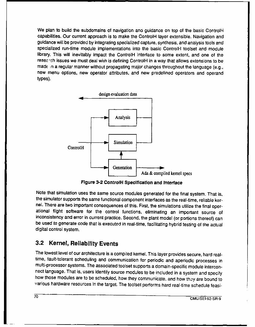
We plan to build the subdomains of navigation ano guidance on top of the basic ControlHcapabilities. Our current approach is to make the ControlH layer extensible. Navigation andguidance will be provided by integrating specialized capture, synthesis, and analysis tools andspecialized run-time module implementations into the basic ControlH toolset and modulelibrary. This will inevitably impact the ControlH interface to some extent, and one of therese-uCh issues we must deal with is defining ControlH in a way that allows extensions to bemadE n a regular manner without propagating major changes throughout the language (e.g.,new menu options, new operator attributes, and new predefined operators and operandtypes).
design evaluation data
Analysis
ContrlH • Simulation
Generation
Ada & compiled kernel specs
Figure 3-2 ControlH Specification and Interface
Note that simulation uses the same source modules generated for the final system. That is,the simulator supports the same functional component interfaces as the real-time, reliable ker-nel. There are two important consequences of this. First, the simulations utilize the final oper-ational flight software for the control functions, eliminating an important source ofinconsistency and error in current practice. Second, the plant model (or portions thereof) canbe used to generate code that is executed in real-time, facilitating hybrid testing of the actualdigital control system.
3.2 Kernel, Reliability EventsThe lowest level of our architecture is a compiled kernel. This layer provides secure, hard real-time, fault-tolerant scheduling and communication for periodic and aperiodic processes inmulti-processor systems. The associated toolset supports a domain-specific module intercon-nect language. That is, users identify source modules to be included in a system and specifyhow those modules are to be scheduled, how they communicate, and how thy are bound to"various hardware resources in the target. The toolset performs hard real-time schedule feasi-
70 CMU/SEI-92-SR-9

bility and sensitivity analysis; timing, data, and control security verification; reliability analysis;and then automatically assembles the modules into the final system, generating all necessaryscheduling and communication code automatically.
Statically generating the kernel code provides two major advantages. First, it eliminates theneed for many run-time services that must otherwise be provided by an executive (e.g., pro-cess creation and message routing). This can lead to significant improvements in efficiency aswell as reductions in the amount of flight software that must be certified. Second, it facilitatesa static analysis and verification of kernel behavior.
The reliability analysis performed by the compiled kernel toolset is based in part on a specifi-cation of the redundancy management approach used. There are several viable approachesfor redundancy management (e.g., error masking and reconfiguration) and several alternativeconsensus protocols to select from (e.g., triple modular redundancy and Byzantine protocols).We plan to provide a tool to help transform a nonredundant specification into a redundant oneand assist in performing the necessary trade-offs.
Discrete Event Dynamic Systems (DEDS) design and analysts is becoming increasinglyimportant in modern control systems. There are a number of models for DEDS, each of whichserves a different purpose. The lower layers of our system are primarily concerned with thepara-functional requirements of reliability and performance, and we are basing our initial eventprocessing and analysis layer on queueing theory and queueing network models.
Eventually, all real-time scheduling and communication, discrete event and mode change pro-cessing, and hardware redundancy management are likely to be provided using a largely uni-form user interface, analogous to the way we hope to obtain navigation and guidancecapabilities as extensions to ControlH. In the short term, this is complicated by the need to usespecialized forms of specification for queueing systems and redundancy managementschemes. An active area of research for us will be to better integrate reliability, real-timeresource allocation and scheduling, and discrete event specification and analysis, within acommon conceptual framework and user interface.
3.3 Domain Extension
One of our goals is to provide as extensible a product as possible. This may be accomplishedthrough the addition of new analysis tools and source modules within a view, as we observedfor ControlH. This may also be accomplished by the addition of entirely new layers and views.Figure 3-1 shows two such layers that do not fall cleanly within our domain of IGN but for whichexisting tools can be easily integrated with our DSSA product.
The Virtual Application Prototyping System (VAPS) is a commercial tool used to rapidly proto-type cockpit display systems. The VAPS code generator is being modified to produce opera-tional Ada flight software, and such a tool is easily integrated into the overall DSSA system.
CMU/SEI-92-SR-9 71

Uke many organizations, we have an instrumentation system to support real-time testing,debugging and performance measurement in multi-processor targets. As with the layers andviews of our DSSA product, instrumentation is specified using a high-level experimentationlanguage that is compiled into the necessary event and data monitoring code. There are alsodata collection and analysis tools. Such tools can provide powerful development support whenintegrated into a DSSA product.
4 Conclusion
Within our domain there are a number of generally accepted formal models, as well as a num-ber of analysis tools, for GN real-time scheduling and resource allocation, event processing,and hardware fault-tolerance and reliability. What has been lacking is a common softwarearchitecture that supports requirements in all these fields, is subject to accurate analysis, canbe automatically configured and populated, and serves as a core around which a completeintegrated development system for IGN software cen be built.
72 CMU/SEI-92-SR-9

Domain-Specific Software Architectures for Hybrid Control
Richard Platek and James H. TaylorORA Corp .lion301 A Dates D, ie
Ithaca, NY [email protected]
Abstract: The ORA-Cornell University team in the DARPA DSSA project isconcerned with the domain of hierarchical, distributed, intelligent, hybrid controlfor nonlinear systems. By "hybrid" we mean that the resulting system iscomprised of both digital and analog elements. The motivation for this focus isas follows: Software for linear control is a fairly mature field with severalrommercial CAD environments in use containing facilities for automaticgeneration of code. These environments can be viewed as moderatelysuccessful instances of DSSA. The vendors do provide some capability fordesigning, analyzing, and implementing nonlinear controls, but this is generallyad hoc and rudimentary in form. Our team is developing both a mathematicaltheory of nonlinear hybrid control and corresponding prototype software toolswhich support, where possible, the automatic generation of control laws andreal-time software implementations. This theory is being tested on real physicalcontrol problems, and a CAD environment is being developed to encapsulatethe theory and make it available to control engineers. The basis of theenvironment is a flexible package to simulate, analyze and visualize hybridsystems behavior in terms of dynamical systems with discontinuous vectorfields. CAD tools for design will be integrated with this package. 1
The Domain
As part of the DARPA Domain-Specific Software Architecture (DSSA) program a team con-sisting of ORA Corporation and Cornell University's Mathematics Sciences Institute (MSI) isinvestigating an environment for the design, implementation and evaluation of hierarchical,distributed, intelligent, hybrid control. The effort is being monitoreld by Dr.Norman Coleman'slaboratory at the U.S. Army's Armament Research, Development and Engineering Center(ARDEC).
The present stress in the effort is on hybridcontrol, by which we mean an integrated approachto continuous physical devices (mechanical, electrical, hydrmulic, etc.) being controlled by dis-crete computational units (digital cpus). The customary approach to digital control of physical
1. The work described in this article was partially funded as a part of the DARPA-sponsored DSSA Project underContract No. DAAA21-92-C-0013, for US Army AMCCOM, Picatinny Arsenal, NJ 07806-5000.@1992 IEEE. Reprinted, with permission, trom Proceedings of the 1992 IEEE Symoosium on Computer AidedCon' 'System Design; Napa, California, March 17-19, 1992; p. 137. Permission to copy without fee all or partof this material is granted provided that the copies are not made or distributed for direct commercial advantage,the IEEE copyright notice and the title of the publication and its date appear, and notice is given that copying isby permission of the Institute of Electrical and Electronics Engineers. To copy otherwise, or to republish, requiresa fee and specific permission.
CMU/SEI-2-SP.-9 73
__ _ __ _____________________ ___________________________________________________________________

processes is to either take the world's point of view or the computer's point of view. In thefomier, the control problem is solved mathematically using continuous math and the solutions
are implemented using a digital computer to calculate approximations to the continuous con-
trols. These approximations are generally close enough for practical purposes. In the lattercase, the continuous world is replaced by a sampled world anu the problem is viewed entirelyas an exercise in discrete math. In hybrid control, one attempts to study the problem withouteither reducing the discrete to the continuous or the continuous to the discrete.
2 The ApproachAt the present time the mathematical theory does not exist to analyze or design hybrid controlproblems rigorously. Most textbooks in control theory present parallel chapters on continuousand discrete control with, for example, the Laplace transform in the former being replaced bythe z transform in the latter. On the other hand, one can claim that in practice control engineersdeal with hybrid control all the time. It is not unusual in the history of control theory that practiceleads the development of theory. The flyball governor was introduced in the early nineteenthcentury as a piece of effective technology. The theory behind it was first explored in 1868 byJames Clerk Maxwell in his paper "On Governors", which established the field of mathemati-cal control theory [Maxwell 68]. Similarly, a mathematical theory of hybrid control which dealswith mixed logico-differential equations should establish a rationale for what practitioners deal-ing with the digital control of continuous processes have learned to do through experiment andtuning.
The development of the mathematics of hybrid control under this effort is proceding at Cornelland ORA. The Nerode-Kohn paper at the recent IEEE Symposium on Computer-Aided Con-trol System Design reports on some findings [Nerode-Kohn 92]; other work under this effort isreported in Nerode's "Hybrid Systems: A Survey and Models" [Nerode 92] and Yakhnis' "AConcurrency Games Approach To Hybrid Systems". In the latter paper, a game-theoreticapproach to hybrid control is outlined which will support automated extraction of winning strat-egies (i.e., effective control laws) from game formulations of the control problem.
Another innovative approach underpinning our effort is the use of nonlinear dynamical sys-tems theory to support the design and analysis of hybrid controls. To support this, we are work-ing to adapt simulation tools from this area toi solve hybrid control problems. In the last twodecades, the mathematics of dynamical systems has made significant progress in both theworlds of pure and applied science [Guckenheimer 83]. Under the provocative name of"chaos" this mathematics has caught the popular imagination and its vocabularly is enteringcommon educated discourse [Stewart 89]. In addition, the problem of controlling chaos isattracting wide scale attention in the scientific world ([Ott 90], [Bradley 92]).
In our project we are adapting and further enhancing the package dstool which has beendeveloped at Cornell under the direction of John Guckenheimer and his students. This tool isavailable by Internet ftp from Cornell and we are presently changing it so that it can be usedto analyze and simulate hybrid dynamical systems. Principal changes are the integration of
74 CMU/SEI-92-SR-9
trajectories defined by discontinuous vector fields and the extension of algorithms for deter-mining fixed points, bifurcations, and the onset of chaotic behavior. This is done by adoptinga manifold-descriptive approach to phase space; that is, the phase space is covered bypatches with coordinate transformations when patches overlap.
Finally, there have been recent advances in the area of frequency-domain methods for theeffective synthesis of nonlinear controllers that hold substantial promise as a means of auto-matically generating control algorithms and software for nonlinear hybrid control ([O'Donnell91], [Taylor 90]). In addition, we have recently conceived of an extension to this approach thatcan be used as a way to synthesize fuzzy controllers. These approaches will be integrated withthe ORA hybrid control environment to assess their usefulness as DSSA generators.
In order to focus our early efforts we are applying our emerging nonlinear control and hybridsystem theories to the ARDEC test fixture called the Advanced Testbed 1000 (ATB1 000) \cit-e{mattice}. This is a physical simulation (scale model) of a gun with a flexible barrel which canbe aimed and is subject to base motion and recoil disturbances. The control problem is to pointthe tip of the barrel using actuators attached to the barrel's base. Motion pictures of the cannonon the Apache helicopter show that during firing the tip of the cannon appears to behave quitechaotically. Since it is the tip which determines the targeting of the gun the Apache is knownas an "area weapon" as opposed to a point weapon. The ability to control its firing wouldgreatly enhance the military value of the Apache. The ARDEC test fixture is designed to phys-ically simulate situations like the Apache helicopter.
3 ConclusionThe creation of methods and software tools for the automatic generation of instances ofDSSAs for nonlinear hybrid control problems holds great potential for reducing the cost of real-time embedded control software for practical applications. The work under the DSSA Programin general and this contract in particular-should help to realize this promise.
References
[Bradley 92] Elizabeth Bradley. "Mathematics and Computation: Controlling Chaos".Second International Symposium on Artificial Intelligence and Mathematics(Autonomous Control Workshop), 1992.
[Guckenheimer 83]John Guckenheimer and Philip Holmes. Nonlinear Oscillations, DynamicalSystems, and Bifurcations of Vector Fields, Springer-Verlag, New York,Berlin, Heidelberg, Tokyo, 1983.
[Mattice 91] Michael Mattice. "Inertia Wheel Fixture (Problem)", 1991 Automatic ControlConference, pages 2992-2993, 1991.
[Maxwell 68] J.C. Maxwell. "On Governors", Proc. Royal Soc. London, volume 16, pages270-283, 1868.
CMU/SEI-92-SR-9 75

[Nerode 92] Anil Nerode. "Hybrid Systems: A Survey and Models", Second InternationalSymposium on Artificial Intelligence and Mathematics (Autonomous ControlWorkshop), 1992.
[Nerode-Kohn 92]Anil Nerode and Wolf Kohn. "An Autonomous Systems Control Theory",1992 IEEE Symposium on Computer-Aided Control System Design, 1992.
[O'Donnell 91] James R. O'Donnell, Jr. and James H. Taylor. "CAE Tools for Nonlinear
Systems Analysis and Design Based on SIDFs", IFAC/IMACS Symposiumon CAD in Control Systems, pages 69-74, 1991.
[Ott 90] Edward Ott, Celso Grebogi, and James A. Yorke. "Controlling Chaos",Chaos: Proceedings of a Soviet-American Conference (American Instututeof Physics), 1990.
[Stewart 89] lan Stewart. Does God Play Dice? The Mathematics of Chaos, BasilBlackwell Inc, 1989.
[Taylor 90] James H. Taylor and James R. O'Donnell, Jr. "Synthesis of NonlinearControllers with Rate Feedback Via SIDF Methods", 1990 Automatic ControlConference, pages 2217-2222, 1990.
[Yakhnis 92] Alexander Yakhnis. "A Concurrency Games Approach to Hybrid Systems,Second International Symposium on Artificial Intelligence and Mathematics(Autonomous Control Workshop), 1992.
76 CMU/SEI-92-SR-9
Application of ProtoTech Technology to the DSSA Program
Frank C. BelzTRW Systems Integration Group
TRW R2g2062One Space Park
Redondo Beach, CA [email protected]
David C. LuckhamStanford University
ERL 456Stanford CA 94305
James M. PurtiloUniversity of Maryland
Department of Computer ScienceCollege Park, Maryland 20742
Abstract: In DARPA's ProtoTech Program, exploration of the prototypingprocess and innovative technologies to support that process has led to anemphasis on (i) multilingual prototyping, (ii) component-based architectures,(iii) architecture evolution, and (iv) rapid derivation of prototypes from pre-existing components and specifications of behavior and connectivityrequirements. These emphases match needs within the DSSA program;consequently a team of ProtoTech participants (TRW, Stanford, and Maryland)is focused on bringing early maturing technology from the Prototyping Programinto the DSSA program. For example, it is unifying the technology (developedat Stanford for modelling, prototyping, and analyzing prototypes of distributed,time-sensitive systems), with the Polylith module interconnection technology(developed at Maryland for building multi-lingual distributed applications out ofpre-existing components). This DSSA team is using such ProtoTechtechnologies as RAPIDE and Polylith to model and prototype architecturesunder development by the other, domain-based DSSA teams. Using the samemodelling techniques on all these domains, we are seeking to identifycommonalities between the DSSA teams' products. Such commonality canincrease the results from the DSSA program by suggesting the development ofcommon technology to be used by most or all teams where appropriate. Thisprocess of identifying commonalities is interwoven with the process oftransferring the ProtoTech technology into use by the other DSSA teams.1
1 Introduction
Prototyping has an essential role in the development of domain-specific software architectures(DSSAs) and in the new reuse-based software development processes and technology thatwill result from their use. Successful prototyping enables rapid evaluation of hypothesizedarchitectures and proposed implementations. This is important during the initial formulation of
1. This work is supported by the Defense Advanced Research Projects Agency and the Office of Naval Researchunder Contract N00014-91 -J-0173.
CMU/SEI-92-SR-9 77

domain-specific architectures, and even more important in the evolution of those architecturesand components satisfying them. Prototyping technology in common use today, however, isunlikely to be sufficient for the new demands of DSSA-based development. The ProtoTechProgram is developing prototyping technology expected to live up to those demands, amongothers, and thereby to contribute to the full realization of the DSSA Program goals.
The ProtoTech Program is a collaborative effort involving several teams of industrial and aca-demic participants, described elsewhere in these proceedings. The ProtoTech teams havebeen cooperatively exploring alternate hypotheses regarding both the nature of prototypingprocesses and the kind of technological innovation that can most effectively improve our abilityto conduct prototyping processes. These investigations have led to an emphasis in the Proto-Tech community on multilingual prototyping, component-based architectures, evolution ofarchitectures, and rapid derivation of executable versions of prototypes both from pre-existingcomponents and from specifications of behavior and connectivity requirements. These con-cerns correspond, point by point, with needs within any DSSA-based approach to softwaredevelopment.
Some of the ProtoTech investigations are already capable of improving the prototyping prac-tice, others will begin bearing fruit in the near future, and still others are likely to achieve theirfirst real impact in a few years. While several participants in the ProtoTech program are alsomembers of domain-based DSSA teams, the DSSA team consisting of three members of theCPL/CPS community, TRW, Stanford and the University of Maryland, is attempting to bringselected early-maturing ProtoTech technologies to bear in multiple DSSA team efforts and,through the process of interacting with those teams, to identify commonalities among themthat can be exploited in the DSSA program.
2 Our Research HypothesisThe DSSA program is based upon the observations that (i) distinct software applications canhave common architectures, (ii) such common architectures can enable efficient reuse of com-ponents across such applications, and (iii) such common architectures are most easily recog-nized in specific application domains, in part because the body of widely understood conceptsfor a particular problem domain helps to overcome substantial differences in the representa-tions of the applications.
We hypothesize that the kinds of generalizations that enable the identification of commonarchitectures within a problem domain can be applied to identify (sub)architectures that arecommon to applications in several domains.
We are testing that hypothesis by employing technology from the ProtoTech program to rep-resent architectures and to analyze them. Specifically, the Prototyping Language and System[Belz 90], developed by the Stanford/TRW team and the Polylith Software Bus [Purtilo 92], amodule interconnection system developed by the University of Maryland, emphasize the evo-
78 CMU/SEI-92-SR-9

lutionary development of application architectures as part of the process of prototyping appli-cations. These are the principal technologies from the ProtoTech program that we are using to:
"* identify common architectural components among the architectures of the domain-focussed DSSA contractors,
"* define modular components, separating interfaces from (possibly multiple)implementations,
"* specify component interfaces, including where appropriate specification of functionalbehavior, concurrent behavior consisting of synchronization and inter-communication, and timing requirements,
"* specify the topology of distributed dataflow and control of communication betweencomponents,
"* identify generic components from which different components of separate domainarchitectures can be derived by well defined development paths,
"* deliver a specialized version of an architecture description language and system(derived from RAPIDE and Polylith) for modelling and evaluating DSSAarchitectures,
"• show how this architecture description system can serve as a ModuleInterconnection Facility sufficient to support the interoperability requirements of theDSSA architectures, i.e., provide an ability to define architectures whosecomponents are implemented in multiple languages (such as Ada, C++ and VHDL),
"* show how this technology could be incorporated in tools developed under the DSSAprogram for eventual inclusion in software development environments,
"• provide feedback to the ProtoTech Program to ensure that its technology isapplicable to the DSSA Program.
If we successfully demonstrate our hypothesis, we expect the consequences to include animproved ability within the DSSA program to generate architecture-based application compo-nents and tools, with a reduced risk that the program will generate several isolated domains,each with incompatible tools to support rapid application development. The latter risk is cur-rently the state of practice with fourth generation technology and its amelioration is a signifi-cant, if implicit, goal of the DSSA program.
3 The Enabling TechnologyAmong the ProtoTech technologies, our work will rely extensively on the Prototyping Lan-guage and Tooltet, the Polylith module interconnection technology, and the results of Proto-Tech's Module Interconnect Formalism Working Group (MIF WG) efforts.
The RAPIDE Prototyping Language and ToolsetRAPIDE is a prototyping language with supporting tools that provide features for specifyingand building prototypes of distributed time-sensitive systems. Many of the concepts embodiedin have evolved from prior work at Stanford ([Augustin 901, [Luckham 871, [Luckham 90]).
CMU/SEI-92-SR-9 79

Two versions of RAPIDE have been defined: RAPIDE 0.2, a preliminary proof-of-principal ver-sion, with tools; and RAPIDE 1.0, a full prototyping language, designed as a language frame-work which can be tailored to meet domain-specific requirements as needed. RAPIDE has thefollowing features:
"* Module Specifications: Module interface specifications contain:
" general properties of module operations, independent of anyimplementation details, so that varying implementations are possible.These properties include definition of values returned by modulefunctions, timing behavior of module operations, and exceptionpropagation situations.These specifications are equally suitable for software modules and forhardware modules. They permit a variety of currently separate techniquesto be used in specifying DSSA's, including input/output specifications,finite state machine transitions, and interval timing specifications.
"* Requirements needed from the using environment in order for a moduleto operate effectively; these include generic parameter restrictions, andother reuse requirements.These specifications, which deal primarily with reuse and reconfigurationof modules, provide critical data for a variety of tools supportingconfiguration of architectures and reuse of components.
" Communication Architectures: Communication architectures define how themodules in a system communicate, what kinds of data, timing and data throughputsare allowed, and the synchronization or independence of operation betweenmodules. In general, communication architectures can be dynamic, or variableduring the system operation.
" Design Hierarchy: RAPIDE 1.0 provides powerful and simple features based onobject-oriented inheritance [Mitchell 91], and mapping constructs to capture designhierarchy. Mappings are a new language concept, and are based on the concept ofpatterns of events. This feature is used to capture design decisions (i.e., designerknowledge) involving hierarchical refinement of components. Using patternmappings it is possible to specify in RAPIDE how a component module, which hasbeen specified abstractly at one level in a system design, is expanded into a detailedarchitecture at a lower design level. Design hierarchy is a critical and often used toolin architecture specification. One such example is the refinement of acommunication system into layers of protocols, each layer being more and moredetailed and hardware-specific.
" Executable Prototypes: allows prototype systems to be implemented in a simpleconcurrent rule-based language, or RAPIDE 1.0) in other languages such as Ada orVHDL. Implementations of both modules and communication architectures aresupported. The primary purpose is two-fold: (i) to build executable models rapidly foranalysis of requirements, and to support gradual evolution of systems from eitherearly prototypes or one application to another. RAPIDE allows implementations ofcomponents to be introduced into the system one component at a time, and testedin the overall system design framework containing prototypes or implementations ofall other modules.
80 CMU/SEI-92-SR-9

" Derivation Histories: The RAPIDE support system will keep a history of howvarious versions of module components and architectures are built out of previousversions. This facility will be based on an object-oriented inheritance feature of thelanguage. It is a powerful facility in reconfiguring systems to meet new requirementswhile at the same time ensuring against various kinds of errors.
" Tools for Analytical Prototyplng: The present RAPIDE system is based on themodel of distributed computations as partially ordered sets of events (Posets)[Meldal 91]. The ordering between events expresses whether an event causedanother event or whether two events occurred independently. Timing of events bymeans of timestamps is also included in RAPIDE computations. According tomodem theory of concurrent computation, the Poset model provides the mostaccurate information about behavior of a distributed system, and has demonstrableadvantages over the use of linear traces. The RAPIDE toolsuite provides graphicalcapabilities for manipulating and viewing partially ordered and timed computations,and also tools for automatically checking specifications against such computations.Other toois are currently being designed and built to support: (i) analysis ofarchitecture specifications using subtype and inheritance information,(ii) reconfiguration of architectures to meet changes in requirements, including, forexample, selection of modules for reconfiguration of an architecture, (iii) test datageneration from specifications to support the use of DSSA's to test specificapplications, (iv) transition from RAPIDE systems to specific Ada implementations.
" Processes of Evolutionary System Development: The RAPIDE 1.0 language andsupport system is designed to support processes of gradual evolution of systems.The type system captures the development paths of both components andarchitectures. It provides a basis for checking some aspects of the correctness ofsuch reuse activities as component replacements. The runtime analysis tools basedon Posets with timing provide a capability to analyze changes in communication,synchronization, and timing, and compatibility with requirements. The designhierarchy features allow low level detailed implementations to be compared forconsistency with high level specifications.The sum total of these capabilities is a powerful support system for developingrigorous processes of system evolution and refinement based on behavioralprototyping and analysis in conjunction with formal specifications.
Status of Prototyping in RAPIDEThe capabilities described above are supported by an experimental prototype toolset. Exper-iments demonstrating the ability to prototype in RAPIDE a wide variety of small example sys-tems from differing domains have been carried out. Examples of small systems include acommunication protocol, a telephone PBX, a disk controller, a satellite communication sched-uler, and simple hardware devices including a 16-bit CPU, and examples drawn from otherDSSA projects: a helicopter on-board flight program from the IBM avionics-domain effort, andthe controller/meta-controller model from the CIMFLEXITeknowledge effort. The architecturesof some of these examples involve three or four levels of hierarchical refinement. Developmentof a set of guidelines for evolutionary prototyping is underway.
CMU/SEI-92-SR-9 81

Polylith
Our planned experiments entail comparing and evaluating ;oftware that has been developedfor specific domains by several contractors. Success in tnese experiments requires that wehave a practical way to integrate such software. This requirement directly corresponds to onefrom the ProtoTech program, where the focus is on rapid configuration of prototyping appara-tus. Available software components must be easy to use, without regard for their implementa-tion language or original execution platform.
The Polylith software interconnection system at the University of Maryland helps meet theserequirements for ProtoTech ([Callahan 91], [Purtilo 88], [Purtilo 91 a], [Purtilo 91 b], [Purtilo 92]).Polylith provides:
1. a module interconnection language (MIL) for developers to express their soft-ware configurations abstractly.
2. a packaging system for analyzing configurations and then generating allstubs, build commands and other interfacing structures according to thedeveloper's abstract interfacing decisions.
3. a run-time system providing various forms of communication support for aconfiguration's components, especially those from diverse languages andplatforms. This run-time system is referred to as an implementation of the'software bus', described below.
A version of Polylith has been distributed for use within the ProtoTech community, and is nowbeing used as the carrier for many of the community's ideas. The version of Polylith that hasresulted from evolution within ProtoTech will form a new baseline for use in our DSSA activi-ties.
Whether for prototyping or for experimenting with heterogeneous domain-specific software,the critical problem within interconnection is clear: current ad-hoc methods for interconnectingsoftware forces programs to become intricately coupled with their environment. The compo-nents of a realistic application are not cohesive, since they must serve many functional andnon-functional requirements at the same time. Examples of non-functional requirements thatapply to application components are coercion of data representation and relocation of the databy available media. These requirements accumulate primarily due to limitations in the inter-connection system, such as the mixing of host platforms or implementation languages. Thiscoupling limits reuse of components within prototyping environments, and would impedeDSSA experiments with components having diverse origins.
To solve this problem, we postulated a new software organization to encapsulate communica-tion and data transformation tasks. This is the software bus organization, where an 'abstractbus' is the specification of interfacing properties to be encapsulated, and a 'run-time bus' is aprogram that implements the developer's encapsulated decisions. This allows developers todecouple the implementation of interfacing requirements from the treatment of functionalrequirements. Thus programmers are able to code without having to pay constant attention toconstraints imposed by the underlying architectures, language processors or communication
82 CMU/SEI-92-SR-9

media. Such constraints cannot be completely ignored, but our primary result is that they canbe isolated for independent treatment without loss of performance at run time. Moreover, once
the application has been built for one execution environment, then tailoring the interface needs
for execution in other environments is a separate and automated activity.
Describing the direct relation between arbitrary software components is difficult. Describinghow an arbitrary component relates to the abstract bus is easier, and, once this is done, devel-opers have a common basis for relating that component to others that have been similarly
specified. The Polylith system demonstrates our software bus organization (currently on Unix
platforms), and continues to evolve as the ProtoTech Module Interconnection Formalism (MIF)Working Group converges towards specification of a 'prototyping bus' suitable for use withinthe community. For DSSA, we will adopt the software bus organization to serve both pragmatic
interconnection needs and abstract module comparison activities.
The Module Interconnection Formalism Working Group
The ProtoTech program achieves a substantial interaction through technology-specific work-ing groups. Among the most important to DSSA is the Module Interconnection FormalismWorking Group (MIF WG). This Working Group is charged with developing and formalizingemerging community consensus on desirable models and technologies for module intercon-nection of incrementally-developed systems of the future.
The MIF WG must address a very broad set of services, requirements, and scenarios. Exam-ples of these issues are value passing mechanisms, inter-language integration, inter-machineintegration, transmission of values having abstract types, pointer data, stream data, synchro-nization, generalized exception handling, implementation of call-back mechanisms, implicitversus explicit invocation, and performance considerations.
The need for a component-based approach is clear, and there appears to be a general con-sensus within the MIF WG that a high-level notation for describing the components and theirinterconnections is needed. There is also consensus that formalisms are needed that supportdefinition of interconnection service layer, the "prototyping bus". In some cases, the Polylithinterconnection system has been used to prototype these capabilities to enhance the discus-sion.
Our approach, using the Polylith software interconnection system in union with is entirely com-patible with the consensus emerging from the MIF working group.
4 Melding Research and Technology Transfer
Our effort is both a research and a technology transfer task. We are interweaving both aspectsof our effort, making each work on behalf of the other.
Achieving technology transfer is a complex process, involving management of many organi-
zational, interpersonal, and technical factors [Przybylinski 91]. Our approach emphasizes the
CMU/SEI-92-SR-9 83

commitment process, which we merge with our experimental method. The commitment pro-cess, as described in Przybylinski, Fowler, and Maher, has three phases: Information Transi-tion (contact, awareness, understanding), Pilot Test (trial use), and Technology Transition(adoption, institutionalization). Correspondingly, we have a three-phase model of technologytransfer. For each domain-based DSSA team we will go through these three phases; we willoverlap our interaction with the teams over time.
Phase 1: "In-house" investigations. In this phase we determine theapplicability of the ProtoTech technology to the needs of the domain-basedproject. Our team exerts the effort involved; we develop executablearchitecture descriptions that serve as illustrative prototypes addressingarchitectural issues the domain-based team is grappling with. A preconditionfor this investigation is a prior identification on the part of the domain-basedteam that there is some potential applicability of the technology. Expectedpositive postconditions include recognition by the domain-based team thatthe technology is in fact applicable, and worth investing in further.
Phase 2: Collaborative investigation. In this phase we demonstrate that thetechnology is applicable, and begin the adaptation of the domain-teamprocess to include the technology. The heart of the activity is pilot architectureprototy:.e development, in which both our team and the domain-based teamshare the effort of using the prototyping technology in the pilot. Preconditionsinclude satisfactory completion of Phase 1, management commitment on thedomain-based team, available resources, and appropriate timing. Expectedpositive postconditions include increased commitment to the technology bythe domain-based team, improved understanding by our team of thecommonality of the pilot architecture with those of other teams, and usefulfeedback to the ProtoTech community about the requirements on prototypingtpchnology imposed by DSSA-based development approaches.
Phase 3: Client usage. The purpose of this phase is to integrate the use ofthe technology in the domain-based team's process. The activity is selectedand conducted solely by the domain team. This phase requires mature,robust technology, successful Phase 2 investigation, and managementcommitment. Expected post-conditions include improved acceptance,understanding and feedback.
The principal research objective, to identify important commonalities among the approachesof the separate domain-based teams, is well served by the three-phase model. Phase 1 cre-ates intimate involvement with the team, their architectural approach and artifacts. It also startsthe process of identifying common elements of the teams' approaches by using a commonrepresentation technology for the designs and architectures from the domain-teams. By phase3, all parties have a very clear pictures of the architectures, the technology we have providedto represent that architecture, and the commonalities among the architectures.
References
[Augustin 90] L. Augustin, D.C. Lur,, iam, B. Gennart, Y Huh and A. Stanculescu,Hardware Design ar C 3imulation in VAL / VHDL. Kluwer AcademicPublishers, October 1990, 322 pages.
84 CMU/SEI-92-SR-9

[Belz 90] F.C. Belz and D.C. Luckham, A New Approach to Prototyping Ada-BasedHardware/Software Systems, in Proceedings of the ACM Tri-AdaConference, Baltimore. December 1990.
[Callahan 91] J. Callahan and J. Purtilo, A Packaging System for HeterogeneousExecution Environments, IEEE Transactions on Software Engineering, June1991.
[Luckham 87] D.C. Luckham, F.W. von Henke, B. Krieg-Brbickner and 0. Owe, ANNA -ALanguage for Annotating Ada Programs, Springer-Verlag Lecture Notes inComputer Science, LCNS No. 260, July 1987, pp. 1-140.
[Luckham 90] D.C. Luckham, Programming with Specifications. An Introduction to Anna, ALanguage for Specifying Ada Programs. Springer-Verlag Texts andMonographs in Computer Science Series. October 1990, pp. 1-421.
[Meldal 91] S. Meldal, S. Sankar and J. Vera, Exploiting Locality in Maintaining PotentialCausality, in Proceedings of the 1991 Symposium on Principles and Practiceof Parallel Programs (PPoPP).
[Mettala 92] E.K. Mettala, J.R. James, N.P. Coleman, E.J. Gallagher, Jr., R.L. Harris andJ.G. Smith, Domain Specific Software Architectures: Government Needs andExpectations, in Proceedings of the Symposium on Computer-Aided ControlSystem Design, Napa, California, March 1992.
[Mitchell 91] J.C. Mitchell, S. Meldal and N. Madhav, An Extension of Standard MLModules with Subtyping and Inheritance, in Proceedings of Conference onPrinciples of Programming Languages, 1991.
[Przybylinski 91] S.M. Przybylinski, P.J. Fowler and J.H. Maher, Software TechnologyTransition, Tutorial presented at the 13th International Conference onSoftware Engineering, Austin, TX, May 12, 1991.
[Purtilo 88] J. Purtilo, D. Reed and D. Grunwald, Environments for Prototyping ParallelAlgorithms, Journal of Parallel and Distributed Computing, vol. 5, pp. 421 -437, 1988.
[Purtilo 91a] J. Purtilo and P. Jalote, An Environment for Developing Fault TolerantSoftware, IEEE Transactions on Software Engineering, Vol. 17, February1991, pp. 153-159.
[Purtilo 91b] J. Purtilo and P. Jalote, An Environment for Prototyping DistributedApplications, Computer Languages, Vol. 16, no. 3/4,1991, pp. 197-207.
[Purlilo 92] J. Purtilo, The Polylith Software Bus, to appear in ACM Transactions onProgramming Languages and Systems. Currently available as University ofMaryland TR-2469.
CMU/SEI-92-SR-9 85

REPORT DOCUMENTATION PAGEI&. REPORT SECURITY CLASSIFICATION l b. RESTRICTIVE MARKINGS
Unclassified None
2a. SECURITY CLASSIFICATION AUTHORITY 3. DISTRIBLITON/AVAILABIL1TY OF REPORT
N/A Approved for Public Release2b. DECLASSIFICATION/DOWNGRADING SCIHEDULE Distribution UnlimitedN/A
4'. PF..RFORNMLNG ORGANIZATION REPORT NUMBER(S 5. MONTI'ORING ORGANiZATION REPORT NUMB ER(S)
CMU/SEI-92-SR-9
6a. NAME OF PERFORMING ORGANIZATION 6b. OFFICE SYMBOL 7a. NAME OF MONITORLNG ORGANIZATION
Software Engineering Institute (if applicable) SEI Joint Program OfficeSEI
6c. ADDRESS (City, State and ZIP Code) 7b. ADDRESS (City, State and ZIP Code)
Carnegie Mellon University ESD/AVSPittsburgh PA 15213 Hanscom Air Force Base, MA 01731
88. NAME OFFUNDING/SPONSORING 8b. OFFICE SYMBOL 9. PROCUREMENT INSTRUMENT IDENTIFICATION NUMBERORGANIZATION (if applicable) F1 962890C0003
SEI Joint Program office ESD/AVS
8c. ADDRESS (City, State and ZIP Code) 10 SOURCE OF FU'NDING NOS.
Carnegie Mellon University PROGRAM PROJECT TASK WORK UNITPittsburgh PA 15213 ELEMENT NO NO. NO NO.
63756E N/A N/A N/A11. TITLE (Include Security Classification)
LTC Erik Mettala and Marc H. Graham, eds.
12. PERSONAL AUTHOR(S)
13a. TYPE OF REPORT 13b. TIME COVERED 14. DATE OF REPORT (Yr., Mo., Day) 15. PAGE COUNT
Final IOM TO June 1992 85 pp.16. SUPPLEMENTARY NOTATION
17. COSATI CODES 18. SUBJECT TERMS (Continue on reverse of necessary and idetnufy by block number)
FIELD GROUP SUB. GR. Avionics Software Domain-Specific Software Development
Command and Control Software Software Architecture
Control Software Software Reuse
19. ABSTRAU? (Continue on reverse if necessary and identify by block number)
The DARPA Domain Specific Software Architecture Program (DSSA) is a five-year effort that has been activesince July 1991. This document contains an overview of the work being done in the program as of July 1992.
Software architectures serve as frameworks for software reuse. Domain-specific software architectures alsoserve as a common language in which domain engineers can discuss, understand and teacn the principles oftheir craft.
There are six independent projects within the DSSA program. Four of these projects are working in specific,
(pwe.se turn os e
20. DISTRIBUTION/AVAILABILITY OF ABSTRACTr 21. ABSTRACT SECURITY CLASSIFICATION
UNCLASSIFIED/INLITrED SAME AS RPTDTIC USERS* Unclassified, Unlimited Distribution
22a NAME OF RESPONSIBLE I'DIVID)UAL 22b. TELIEPIIONE NUMBER (Include Area Code) 22.. OlICE SYMliOl
John S. Herman, Capt, USAF (412) 268-7631 ESD/AVS (SEI)

ABSTRACT --conmnued from page one, block 19
military-significant domains. Those domains are Avionics Navigation, Guidance and Flight Director for Heli-copters; Command and Control; Distributed Intelligent Control and ManaCement for Vehicle Management;Intelligent Guidance, Navigation and Control for Missiles. In addition, there are two projects working on under-lying support technology. Hybrid (discrete and continuous, non-linear) Control and Prototyping Technology.
This report contains brief descriptions from each project and an overview.