ad-a247 138 ,ags ---- ~ ~1111111 ii11 li111 111 ii 1el i11111 92-05520 q2 3 02 14 2 1iii i1il 111111...
TRANSCRIPT

AD-A247 138 ,AGS _______
---- ~ ~1111111 II11 li111 111 1El II I111111.AGI"S ONU10LY L10#" blank) 2. REPORT EATS 11. R10047 MEP AND VATIS COVIRSO
MI _ _ __ 91/1)/29 -+ - ' 90/1.1/1-91/10/31. TITE AN SUBITLES. FUNDVIN NUMBERS
A BIOLOGICAL MODEL OF THE EFFECTS OF TOXIC SUBSTANCES -
Annual Technical Report No. I C
6. AUoA) . ".F49620-9 1-C-0012
Robert P. Tuckett, Ph.D. I C-c7. ;1060IN B GNIZAtION INANII AN 2 )~S E~B 5NGRUNIZAVIrli
REPORT NIUMSER
421 Wakara Way, #130 L 01Salt Lake City, UT 84108
9. SPONSORING IMONITORCNG AGENCY NAMI(S) AND ADO)ISS(ES) 10. SPON.SORING IMONITORINGUSAF AFSC 'AGINCY REPORT NUMBER
Air Force Office of Scientific Researchi/PbrBldg. 410 -92 0001-Bolling AFBWashington. D.C. 20032-6448
II. SUPPIEMINTARY NOTES
Ila. DtSTRISUTION I AVAILAMILTY STATEMENT 12b. 3310011314O coot
Approved for public releaseDistribution unlimited
13. AISTRACT (Maximum 20ronW
Due to the basic nature of military operations, it is sometimes necessary forAir Force personnel to be exposed to toxic chemicals in their work environment, eitheras a protracted low-level exposure or as a high-level, acute exposure. The Draizerabbit eye test for acute irritancy has come under severe criticism by the animalrights movement and has undergone legislative restrictions. Therefore, the tissueculture test being developed is likely to commercial as well as scientific benefit.
Progress by Topical Testing during the past year has been on a number oftechnical fronts including the development of data collection software and a methodfor delivery of microquantities of toxic chemicals to individual nerve cells in tissueculture. The neuronal cultures are now viable and reproducible, and their responseto a variety of chemical stimuli has been recorded. Corneal epithelial cultures havebeen viable for a number of months. A number of strategies have been explored toexpand the corneal epithelial culture and thus make it a viable commercial system.
In summary, Topical Testing has made substantial gains in the development ofa commercial assay system, and next year will focus on testing the system's responseto different classes of toxic chemicals.
14. SUBJECT TIRMS IS. NUMBER Of PAGES
Bioassay, Environmental toxins, Detoxification, Tussue Culture 61 -
K? SCUIMIM "11PASIFTION 1.SICUIRVT CLAIFICATION It. SICURITY40KY CLSIIA1OU2 JWIJATIONO'A$STRA'AOf REPORT O9 THIS PAGE OF AJSTRACT SAR
Unclassified U U• , | _ __ '. .. . . I II "I
TABLE OF CONTENTS
TABLE OF CONTENTS ....................... ......................... 1
LIST OF ABBREVIATIONS ................... ........................ 2
LIST OF TABLES ...................... ......................... 3
LIST OF FIGURES ...................... ......................... 4
GANTT CHART .................. ......................... 5
THE SPECIFIC OBJECTIVES OF THE RESEARCH ........... ............... 6
RESULTS TO DATE ........................ ......................... 9Introduction ...................... ......................... 9Tissue Culture ...................... ........................ 9
Trigeminal Neuron Culture ............. ................ 9Tissue Culture Media ........ ............... .. 12Neuron Migration .......... ................. .. 12Fibroblast Proliferation ........ ............. .. 13Neuron Survival In Culture ...... ............ .. 13
Epithelial Culture ............ ................... .. 14Expanding Epithelial Cultures ..... ........... .. 15Concentrating and Restricting Epithellal Growth . . 16
Summary ................. ......................... .. 21Perfusion system ................ ....................... .. 21Data Acquisition and Analysis Software ...... ............ .. 24System Integration ................ ...................... 26
Vibration Insulation ............ .................. .. 26Manipulator Technology .......... ................. .. 27Recording System .............. .................... 27
Chemical Delivery ................. ....................... .. 27Chemical Delivery Micropipettes ....... ............. .. 27Pipette Loading and Safety Procedures ..... .......... .. 33Multiple Chemical Delivery ........ ............... .. 33
Data Collection ................. ........................ .. 34Voltage Clamp ............... ...................... .. 34Current Clamp ................. ..................... 35Response to Chemical Stimuli ........ .............. .. 35
PROGRESS TOWARDS ACHIEVING THE SPECIFIC OBJECTIVES ... ......... .. 53GANTT Charts .................. ......................... 56
PUBLICATIONS .................. ......................... 58
PROFESSIONAL PERSONNEL ................ ....................... .. 59Topical Testing Personel ............ ................... .. 59Employees through subcontract with University of Utah ....... .. 59Consultants ................... ......................... 59
INTERACTIONS .................. ......................... 60Conferences ................... ......................... 60Interactions with Air Force Laboratories ...... ........... .. 60
PATENTS AND INVENTIONS ................ ....................... .. 61
1
92-05520q2 3 02 14 2 1III I1il 111111

LIST OF ABBREVIATIONS
DMEM Dulbecco's Modified Eagle's Medium
KGM Keratinocyte Growth Medium
HBBS Hank's Balanced Salt Solution
PC Personal Computer
EMS Expanded Memory System
DAS Data Acquisition System
MHz Mega Hertz
kHz kilo Hertz
Mbyte Mega byte
AM micro Molar
mM milli Molar
11 micro liter
Am micro meter
1C*.n~o LAI_ _
2-
2

LIST OF TABLES
TABLE I Specific Objectives ............... ................... 5
TABLE II Progress Toward Specific Objectives .... ........... .. 56
TABLE III Specific Objectives for Second Year .... ........... .. 57
3

LIST OF FIGURES
FIGURE 1. ......................... .............................. 10
FIGURE 2 ........................ .............................. .11
FIGURE 3 ........................ .............................. .17
FIGURE 4 ........................ .............................. .20
FIGURE 5 ........................ .............................. .22
FIGURE 6 ........................ .............................. .25
FIGURE 7 ........................ .............................. .28
FIGURE 8 ........................ .............................. .31
FIGURE 9 ........................ .............................. .37
FIGURE 10 ....................... .............................. 38
FIGURE 11 ....................... .............................. 39
FIGURE 12 ....................... .............................. 40
FIGURE 13 ....................... .............................. 42
FIGURE 14 ....................... .............................. 43
FIGURE 15 ....................... .............................. 44
FIGURE 16 ....................... .............................. 45
FIGURE 17 ....................... .............................. 46
FIGURE 18 ....................... .............................. 48
FIGURE 19 ....................... .............................. 49
FIGURE 20 ....................... .............................. 50
FIGURE 21 ....................... ...............................
4

1-4
0 - Io Nl
)0 P
00
1-44
o b
W4
o4 to Uw r- 4"4 "4 m 1., 104
:3 :0. 0~ 0 P.bO ica ~ .9 0 0 tr 0-".- U) 4 04' la ' . -
r ~ ' O0 444 4.' 4 0 r4 l4r-4.4 .W 41- ýl 44 l~
4. 0) 0 0) coU ~ 0
U~- 0 rU 4 v-4

SPECIFIC OBJECTIVES OF THE RESEARCH
The contract is to continue research and development of a prototypephysiological model for monitoring the effects of toxic chemicals and furtherelucidate the mechanisms of action of toxic chemicals on the peripheral sensorynervous system. Specific objectives follow:
1. Selection of a standard pollution stimulus. Because of the complexity andvariety of chemical species that have been tested with the in vivo Draizeeye test and because of the necessity of comparing Topical Testing's invitro model with the in vivo data, definition of a standard pollutentstimulus will require testing of a wide variety of compounds. Theobjective will be to compare the response of neurons grown in culture withand without enrichment with corneal epithelium. The working hypothesis isthat since neurons that innervate cornea are specifically reactive tonoxious stimuli, there will be a shift in the response properties of theneurons in co-culture with corneal epithelium such that a significantlygreater number of neurons have nociceptive properties and thus areresponsive to irritant and noxious chemical stimuli. (The membraneproperties of the neurons in both cultures will also be compared.)
2. Develop a perfusion system which can rinse away the chemical stimulus inbetween stimuli. A perfusion system will be implemented which minimizesthe electrical noise produced by the pump and optimizes methods ofsterilizing and cleaning the system after each day's use.
3. Evaluate how long cultures must grow before testing. Determination of theminimal length of time neurons must be in culture before testing involvesevaluating the health of the neuron as measured by parameters such as theresting action potential and stability of recording and also thespecificity of response to chemical stimuli.
4. Evaluate different data acquisition systems (DAS) to determine which bestsuits current application. DAS systems will be evaluated for speed,price, and compatibility with IBM PC compatible computer systems. Thecompatibility of the data acquisition systems with high speed PC computersystems will also be evaluated as well as the specifications of computersystems which can sample and display the data at high resolution. (It isestimated that 10 kHz will be an adequate sample rate to maintain dataintegrity.)
5. Continue development of action potential recognition and data summarysoftware. Software development is a critical aspect of commercialefficiency. Means for recording the signals at high frequency forextended periods of time. Stimulus selection, handling and analysis ofdata, summarization, quality graphics, and data backup and storage aresome major issues to be investigated.
6. Make improvements in the total integrated system. There are a number ofaspects to the total system (e.g., chemical delivery, recording,vibration, isolation) which when combined can provide a more efficient andcommercially viable assay system.
6

7. Evaluate current clamp, voltage clamp and fluorescent technologies.Current clamp is the most robust method for measuring membrane properties.Unlike voltage clamp, data integrity is maintained independent of cellgeometry. Hence, current clamp will be used to analyze membraneproperties during the current contract. In addition, the feasibility ofusing voltage clamp in future research efforts will be investigated.Also, the ability of newly developed technology of using fluorescentprobes to monitor changes in ion flow will also be reported. The voltageclamp and fluorescent probe technologies might have advantages inanswering questions in specific experimental situations.
8. Determine whether cell inhlbitor(s) significantly influence thequalitative response to the chemical stimulus in co-culture. Neurons,when grown in isolation, contain a mixture of fibroblasts, and when grownin co-culture with epithelium contain the epithelium plus fibroblasts.The purpose of this task is to determine whether the use of cellinhibitors to slow fibroblast proliferation will have a significant impacton epithelial growth, and if so to investigate other methods of isolatingneurons from fibroblasts in order to obtain a purer co-culture of neuronsenriched with epithelium.
9. Determine whether cell density qualitatively affects chemical stimulusresponse. The possibility that density of neurons plated affects neuronalresponse properties will be tested by plating neurons at differentdensities looking for differences in response to electrical and chemicalstimuli.
10. Determine whether the buffer system significantly influences thequalitative response to chemical stimulus. The recording media mustcontain a buffer to maintain pH within the physiological range. Thebuffer system used in the tissue culture growth media is bicarbonate, andthe cells are maintained in 5Z CO2 in the incubator atmosphere. When thecells are removed from the incubator for recording, there is a choicebetween using HEPES buffer (e.g., Hank's solution) and continuing to usebicarbonate (e.g., Earl's solution). Bicarbonate is technically moredifficult to use because it requires a continual bubbling with CO2 andmonitoring of the pH to maintain medium within physiological limits.Experiments will investigate whether the economically more efficient HEPESbuffer is an adequate buffering system for Topical Testing's technology.
11. Determine whether perfusion solution temperature qualitatively influencesresponse to the chemical stimulus. While being grown in the incubator,the tissue culture is maintained near core temperature (36-37"C).Historically, many, if not the majority, of tissue culture studies haverecorded at room temperature. However, there is a possibility that theresponse to chemicals will be qualitatively different when the culturetemperature is maintained near body temperature. This possibility will beinvestigated.
12. Determine whether rabbit neurons have a qualitatively similar response asrat neurons. Since the traditional Draize test is performed in rabbit, itwill eventually be necessary to compare rat co-cultures with thoseobtained in rabbit. This task will will investigate on a preliminarybasis the feasibility of comparing rabbit and rat responses in tissueculture.
7

The GANTT Chart in Table I shows the original anticipated scheduling oftasks during the contract period. Table II summarizes the tasks performed todate, and Table III shows the anticipated scheduling of tasks over the remainingcontract period.
8

RESULTS TO DATE
Introduction
The purpose of this project is to design a commercial assay system withwhich to assay for pain and irritation using an in vitro test analogous to theDraize eye test in which neurons from the trigeminal ganglion (which normallyinnervates the ocular surface) are grown in culture with the epithelium from theocular surface and thus establish an in vitro assay system for irritation. Theresponse of an individual neuron to a chemical stimulus will be recorded and itsactivation will be suggestive that the stimulus has irritant properties (Fig. 1).
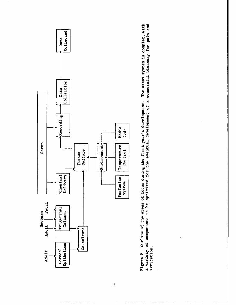
As shown in Figure 2, the experiment can be divided into severalcomponents: First, the tissue culture model has been extensively and continuallymodified with the goal of designing methods which will economically andreproducibly generate co-cultures with corneal epithelium (Figs. 3,4). Thechemical delivery has been designed using microperfusion technology (Figs.5,7,8). The setup itself has undergone refinement and includes a number ofcomponents including the recording system, the tissue culture environment (e.g.,perfusion system), and the recording media. The data acquisition software hasundergone continual improvement (Fig. 6). Lastly, the physiological data isreviewed (Figs. 9-21).
Tissue Culture
Trigeminal Neuron Culture
Several important technical changes have been implemented that havesubstantially improved the neural dissociation.
As established in phase I research, it has been possible to grow neuronsin culture with a collagen substrate. In early phase II, with the advice of Dr.Alcayaga, the dissociation procedure was modified to relatively large cellbodies. Larger cells are suggestive that the dissociation process is more gentleand is yielding more viable cultures.
The initial protocol called for the ganglion tissue to be passed back andforth through a small-tipped glass pipette to break up the tissue fordissociation. A gentler technique is now being used in which after isolationeach ganglion is partially pulled apart with jeweler's forceps and then placedon ice in HBSS (Ca+ and Mg: free). After all the ganglia are isolated, they areplaced i. dissociation solution. With this technique, a greater variety of cellsizes are being obtained. [Larger cells suggest that dissociation procedure ismore gentle (Dr. Alcayaga, personal communication)].
It was discovered that a different dissociation protocol was necessary forfetal animals than for newborn/adult animals. Hence, up until delivery, sensoryneurons in the trigeminal ganglia have little collagen. Hence, it is notnecessary to add collagenase to the dissociation protocol, and the ganglia aredigested with trypsin in HBSS. In the older animals, collagenase and DNAse aid
9

60
56
FIGURE 1. An idealized drawing of the biological model being developed.After dissociation, the neurons (50) from the trigeminal ganglion areplated onto the epithelium and grow out neural processes (54) whichestablish contact with the epithelium. A microelectrode (56) penetratesthe cell body (50) of a neuron. Microquantities of the toxic chemical tobe assayed are then pressure injected in the local vacinity of the neuronthrough a micropipette (60) and the response of the neuron to thepotentially irritant chemicals is recorded.
10
w4J
rI.
0 UU 04
Ul
..0
00
~.0
0.-4
0 U)0 -
0 d1
Aa 5 44.>
No. ba"-4E
Cd w 0"-'.4,>
A.) 0
00 000
a) -lo. co 0
wf4 044 5.4J
4)-b-4 414 w 4 4
5.1- 02
0 00
4.9 1-4 0 d
544
v-11i "-41

in the dissociation process. These changes have substantially improved the yieldin all age groups. Currently, timed-pregnant rats are ordered so that theculturing of neurons is timed to be from 1-2 day old animals. To date, neuronshave been successfully cultured from rats varying in age from 17 day fetal tofully grown animals of up to 500 gm.
Tissue Culture Media. Two types of media have been used: (1) DMEM(Dulbecco's Modified Eagle's Medium) with inactivated horse serum, and (2)Keratinocyte Growth Medium (KGM, from Clonetics) which is a standard medium forgrowing epithelial cultures. It has been found that neurons grow effectively inboth media; however, there are differences in neuronal development.
The DMEM medium produces neuronal cell bodies that are rounded and clearunder phase microscopy. Fibroblasts tend to proliferate in the DMEM; however,it is possible to identify and record from neurons among the fibroblasts. Asmentioned in the previous report, cytosine has been used to inhibit fibroblastproliferation but are currently are not being used. If necessary, fibroblastoutgrowth can be minimized (1) with cell inhibitors, (2) by cell densityseparation techniques, or (3) by using KGM media (see below). The neuronsproduce normal looking action potentials after 2A-3 days and continue to have anormal response.
About 6-8 days post-culture, some neurons begin to die. Other neuronsremain, and responses from the remaining neurons are being recorded for up to 15-20 days in culture. (In earlier experiments, neurons were grown and normalresponses were recorded up to two months in culture.) Alternative causes of thecell death are currently being investigated (see below). As a practical matter,cell death of neurons after 8-10 days may not be an important issue in thecurrent assay system because there a time window of 5-7 days for recording issufficient for assay purposes.
Keratinocyte Growth Media (KGM) has different effects on the neural growththan DMEM. Perhaps most striking is that in 100% KGM, the cell bodies of theneurons have an unusual shape which is "lumpy" in contrast to the smooth circular(or oval) shape of n% *ons grown in DMEM. Axons are often thick and easilyobserved under the microscope. In addition, fibroblast growth is inhibited inKCM and the neuronal cell bodies do not tend to migrate together to form"pseudoganglia" as they do with DMEM (see next paragraph). So far our impressionis that the cells begin to die at about the same time (8-10 days) as in DMEM; butas with DMEM, a number of neurons persist. As the percentage of KGM-to-DMEM islowered, the cells begin to take on more of a "normal" appearance as seen in 100%DMEM. Eighty-percent KGM to 20% DMEM appears to be an optimal percentage forneural growth when grown with fibroblasts. Currently this 80/20 media ratio isbeing used in our neuron cultures.
In the neuron-epithelial cell co-cultures (see below), the neurons appearto grow well in 100% KGM. Hence, the co-cultures are currently being grown in100% KGM to take advantage of the ability of KGM to inhibit fibroblastproliferation while enhancing epithelial proliferation.
Neuron Migration. After about 5-6 days in DMEM, the neurons tend tomigrate in the culture dish and form into clumps which have the appearance of"pseudoganglia" and they are with axons and appear to innervate nearby tissue.Migration is a disadvantage because it is more difficult to identify individual
12

neurons for recording. Migration is minimized by lowering the density of neuronsthat are plated in the dish and by using KGM media.
Fibroblast Proliferation. The fibroblasts tend to "take over" the longerthe neurons are in culture, and it is our impression that the fibroblasts tendto grow in close association and will often contribute to a connective layer overthe neuronal cell body which can make it difficult to record from the neuron.
Different methods for inhibiting fibroblast growth have been investigated:(1) It was found that the neurons grow well in pure DMEM and will grow well in
DMEM + KGM media [KGM is a growth media for keratinocytes]. As KGM concentrationwas increased, an inhibition of fibroblast growth was observed. When 100% KGMwas used, the fibroblasts died and also the neurons would die. Upon closeinspection of neurons in early culture (<l. 5 days), neurons usually grow in closeassociation with fibroblasts. Hence, a conclusion from these preliminary studiesis that neurons might not grow in culture without a supporting "target" cell.
When the neurons are added to epithelial cultures in 100% KGM, the neuronswill grow. Hence, the working assumption is either that epithelium allowsfibroblasts to grow in 100% KGM and the surviving fibroblasts allow the neuronsto grow, or that the neurons can grow with epithelium in the absence offibroblasts.
It is important to minimize the background of fibroblasts because they tendto obscure the neurons and make recording somewhat more difficult in oldercultures and because they tend to compete with epithelial cells in co-culture.Hence, cell isolation procedures are currently being investigated to separate theneurons from fibroblasts.
One technique for isolating neurons is differential adhesion. Immediatelyafter dissociation of the trigeminal ganglion, fibroblasts have a greatertendency to stick to the bottom of a plastic petri dish (Corning) than doneurons. After plating the dissociated cells onto a petri dish, waiting 10 minand then repipetting the neurons, fibroblast numbers were lower. However, asdiscussed before, if the number of fibroblasts drops too low, the neuron culturedoes not survive. By replating the fibroblast-neuron mixture 2-3 times, it ispossible to remove an even greater percentage of the fibroblasts.
Experiments are now beginning to optimize procedures for purifying theneuronal dissociation and neurons are being added to epithelial cultures in 100%KGM. The working assumption is that trigeminal neurons will grow with epitheliumin the absence of fibroblasts. If fibroblasts are necessary, the ratios offibroblasts-to-neurons will be minimized before plating on previously establishedepithelial cultures. Work is planned with our consultant, Dr. K. English, todetermine whether more refined cell separation techniques would be beneficial inthe current application.
Neuron Survival in Culture. Although some neurons survive for up to eightweeks in culture, a high percentage die after about 8-10 days. There are atleast two general alternative mechanisms for cell death: (1) Working Hypothesis.Different types of sensory neurons are predisposed to seek out and innervatespecific types of target tissues. If these targets are not available in the co-culture, the neurons will die. Alternative Hytothesis. Something about thetissue culture environment is detremental to many of the neurons. To test thealternative hypothesis, several factors that contribute to the tissue culture
13
environment have been investigated, including the dissociation process (seeabove), media (see above) and substrate.
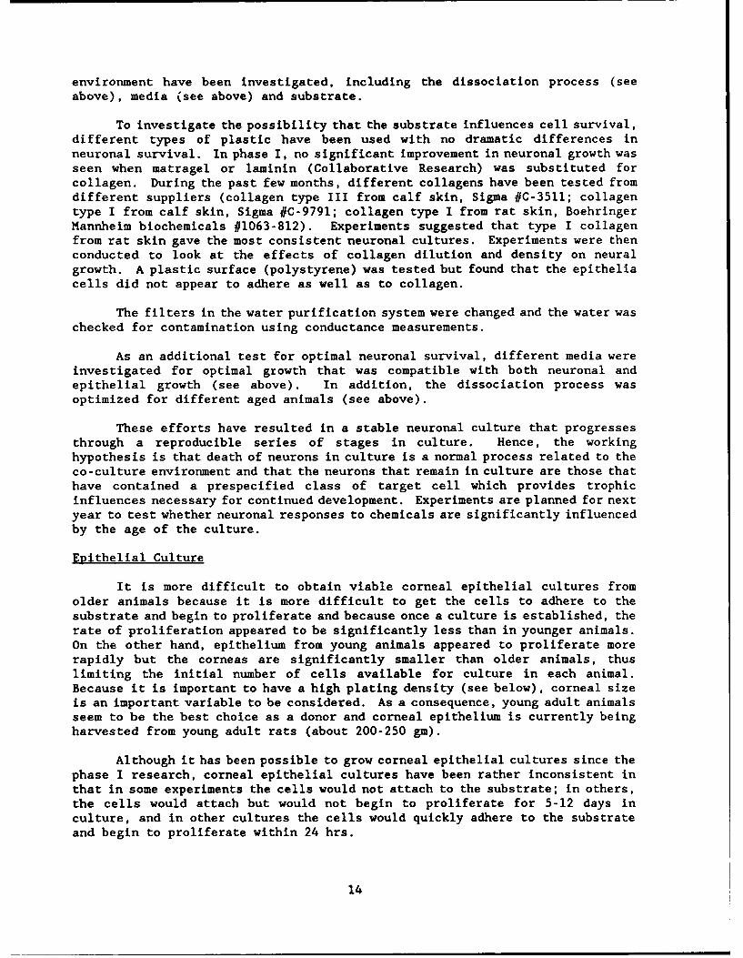
To investigate the possibility that the substrate influences cell survival,different types of plastic have been used with no dramatic differences inneuronal survival. In phase I, no significant improvement in neuronal growth wasseen when matragel or laminin (Collaborative Research) was substituted forcollagen. During the past few months, different collagens have been tested fromdifferent suppliers (collagen type III from calf skin, Sigma #C-3511; collagentype I from calf skin, Sigma #C-9791; collagen type I from rat skin, BoehringerMannheim biochemicals #1063-812). Experiments suggested that type I collagenfrom rat skin gave the most consistent neuronal cultures. Experiments were thenconducted to look at the effects of collagen dilution and density on neuralgrowth. A plastic surface (polystyrene) was tested but found that the epitheliacells did not appear to adhere as well as to collagen.
The filters in the water purification system were changed and the water waschecked for contamination using conductance measurements.
As an additional test for optimal neuronal survival, different media wereinvestigated for optimal growth that was compatible with both neuronal andepithelial growth (see above). In addition, the dissociation process wasoptimized for different aged animals (see above).
These efforts have resulted in a stable neuronal culture that progressesthrough a reproducible series of stages in culture. Hence, the workinghypothesis is that death of neurons in culture is a normal process related to theco-culture environment and that the neurons that remain in culture are those thathave contained a prespecified class of target cell which provides trophicinfluences necessary for continued development. Experiments are planned for nextyear to test whether neuronal responses to chemicals are significantly influencedby the age of the culture.
Epithelial Culture
It is more difficult to obtain viable corneal epithelial cultures fromolder animals because it is more difficult to get the cells to adhere to thesubstrate and begin to proliferate and because once a culture is established, therate of proliferation appeared to be significantly less than in younger animals.On the other hand, epithelium from young animals appeared to proliferate morerapidly but the corneas are significantly smaller than older animals, thuslimiting the initial number of cells available for culture in each animal.Because it is important to have a high plating density (see below), corneal sizeis an important variable to be considered. As a consequence, young adult animalsseem to be the best choice as a donor and corneal epithelium is currently beingharvested from young adult rats (about 200-250 gm).
Although it has been possible to grow corneal epithelial cultures since thephase I research, corneal epithelial cultures have been rather inconsistent inthat in some experiments the cells would not attach to the substrate; in others,the cells would attach but would not begin to proliferate for 5-12 days inculture, and in other cultures the cells would quickly adhere to the substrateand begin to proliferate within 24 hrs.
14

Talks with other investigators (e.g., K. English, D. Forbes) combined withour experience suggests that corneal epithelium is more difficult to grow thecutaneous epithelium. Unlike neuronal cultures, the epithelial cultures requirea high initial density of viable cells before the culture will begin to multiplyand divide. At present, it is uncertain whether the cells must be in actualphysical contact with one another or just be within a certain distance, nor isit known what the total number of cells in the culture must be. Initialexperience suggests that if the cells quickly attach (within 1 hr) to thesubstrate and if the density of neurons is great enough, then the culture willbegin to proliferate within a day. In some cultures although the epithelialcells adhered, the cells did not begin to proliferate for several (3-4) days butthen began to proliferate satisfactorily and grow toward confluence. To date,no clear reason has been found why proliferation is delayed in some cultures.However, in general the sooner proliferation begins the more rapid, uniform andhealthy the cultures appear.
Because a "critical mass" of epithelial cells is required for proliferationand because the rat cornea is a small tissue, it is clear that directly platingthe epithelium onto a 35 mm dish (which requires about 6 corneas/dish) is not anoptimal design for a commercial assay. Hence, alternative means are beinginvestigated to extend the epithelial harvest into a maximal number of cultures.
Expanding Epithelial Cultures. Several strategies are being investigatedto expand epithelial cultures. One technique for expanding cultures in acommercial assay system would be to replate new cultures from seed cultures forseveral cycles. Topical Testing has demonstrated the feasibility of growing thecorneal epithelium to confluence in 35 mm dishes. The cells have then beenredissociated using trypsin and replated, and successful l-to-4 expansions havebeen obtained. Hence, because about 6 corneas are required to originate aculture in a 35 mm dish, then a l-to-4 dilution will yield a dish for every 1.5corneas that were originally harvested. Furthermore, the replating process canbe continued through several cycles. We have demonstrated that the cycle can berepeated at least three times. However, there are several disadvantages to thisapproach: (1) reaching confluence can require a prolonged time period (up to 3-4weeks) and KGM media is expensive; (2) often when epithelial cultures arereplated, some cultures don't take and hence the yield decreases; and (3) perhapsmost importantly, with each replating there is increased likelihood theepithelial cells might tend to lose some characteristics that are important forthe co-culture assay. A modification of the replating technique would be toexpand the epithelial culture to confluence in 35 mm dishes and then replate thecells at high density into several 35 mm petri dishes using 10 mm cloningcylinders to restrict cell migration until after the cells have attached and thecolony has begun to proliferate into several areas using cloning cylinders (Fig.3).
There are reasonable arguments to restrict the epithelial culture to arelatively small area of the 35 mm petri dish: (a) To reduce the possibility ofdeterioration with time, the cultures are recorded for a maximum of half a day;hence, there is no need to grow hundreds or thousands of neurons to study overa large area of each petri dish. (b) Because the volume of the chemical stimulusis very small, it only reaches a small restricted area around the neuron beingstudied, it is quickly diluted by the surrounding recording media and is sweptaway by the perfusion system (Fig. 7). In addition, by first studying neuronsclosest to the exit of the perfusion system, stimulus chemicals will always becarried away from neurons which have not been studied (Fig. 7). (c) Because of
15
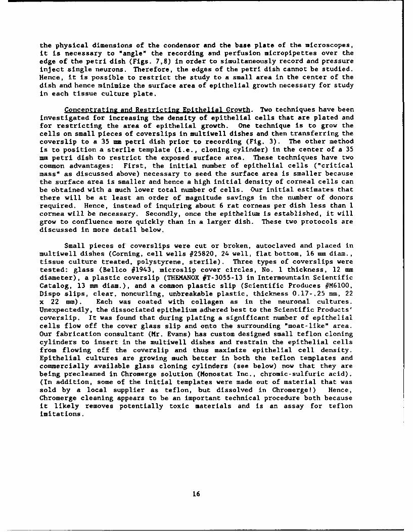
the physical dimensions of the condensor and the base plate of the microscopes,it is necessary to "angle" the recording and perfusion micropipettes over theedge of the petri dish (Figs. 7,8) in order to simultaneously record and pressureinject single neurons. Therefore, the edges of the petri dish cannot be studied.Hence, it is possible to restrict the study to a small area in the center of thedish and hence minimize the surface area of epithelial growth necessary for studyin each tissue culture plate.
Concet.ratinz and Restricting Evithelial Growth. Two techniques have beeninvestigated for increasing the density of epithelial cells that are plated andfor restricting the area of epithelial growth. One technique is to grow thecells on small pieces of coverslips in multiwell dishes and then transferring thecoverslip to a 35 mm petri dish prior to recording (Fig. 3). The other methodis to position a sterile template (i.e., cloning cylinder) in the center of a 35mm petri dish to restrict the exposed surface area. These techniques have twocommon advantages: First, the initial number of epithelial cells ("criticalmass" as discussed above) necessary to seed the surface area is smaller becausethe surface area is smaller and hence a high initial density of corneal cells canbe obtained with a much lower total number of cells. Our initial estimates thatthere will be at least an order of magnitude savings in the number of donorsrequired. Hence, instead of inquiring about 6 rat corneas per dish less than 1cornea will be necessary. Secondly, once the epithelium is established, it willgrow to confluence more quickly than in a larger dish. These two protocols arediscussed in more detail below.
Small pieces of coverslips were cut or broken, autoclaved and placed inmultiwell dishes (Corning, cell wells #25820, 24 well, flat bottom, 16 mm diam.,tissue culture treated, polystyrene, sterile). Three types of coverslips weretested: glass (Bellco #1943, microslip cover circles, No. 1 thickness, 12 mmdiameter), a plastic coverslip (THEMANOX #T-3055-13 in Intermountain ScientificCatalog, 13 mm diam.), and a common plastic slip (Scientific Produces #M6100,Dispo slips, clear, noncurling, unbreakable plastic, thickness 0.17-.25 mm, 22x 22 mm). Each was coated with collagen as in the neuronal cultures.Unexpectedly, the dissociated epithelium adhered best to the Scientific Products'coverslip. It was found that during plating a significant number of epithelialcells flow off the cover glass slip and onto the surrounding "moat-like" area.Our fabrication consultant (Mr. Evans) has custom designed small teflon cloningcylinders to insert in the multiwell dishes and restrain the epithelial cellsfrom flowing off the coverslip and thus maximize epithelial cell density.Epithelial cultures are growing much better in both the teflon templates andcommercially available glass cloning cylinders (see below) now that they arebeing precleaned in Chromerge solution (Monostat Inc., chromic-sulfuric acid).(In addition, some of the initial templates were made out of material that wassold by a local supplier as teflon, but dissolved in Chromerge!) Hence,Chromerge cleaning appears to be an important technical procedure both becauseit likely removes potentially toxic materials and is an assay for teflonimitations.
16

A iMWD
001 T
Cs D
CS S
DPD
PD
CS
FIGURE 3. Illustration of method for expanding the epithelial culture.The epithelium is dissociated and then plated into multiwell dishes (MID).A: illustrates a section from a multiwell dish. Each well contains a ringtemplate (T) constructed of teflon by our fabrication specialist (Mr.Evans). B: A rectangular piece of plastic co-erslip (CS) is centered atthe bottom of each multiwell dish and the teflon template is placed on topof the cover slip. Dissociated epithelial cells are then plated onto thecoverslip. The template has three major purposes: First, it reduces thearea onto which the epithelium is plated, thus minimizing the absolutenumber of cells necessary to obtain a critical density... (figure legendis continued on next page)
17

FIUJRE 3 continued. ... so that the epithelium will begin to proliferate(see text). Secondly, after the template is removed there is some addedarea on the coverslip into which the epithelium can continue to grow, thusallowing the epithelium to continue to grow without maturing and dying.[When the epithelium grows until it is restricted so that it can no longermultiply and divide, it becomes "old" and begins to degenerate. Hence,having an added area for the epithelium to grow into provides an addedtime period for continued health of the culture.] Thirdly, the templateon top of the coverslip provides a barrier so that the epithelial cellswill not flow from the coverslip and onto the surrounding surrounding"moat" around the coverslip in the well. Thus, cells are not lost thatotherwise would remain in the well after the coverslip is removed forstudy. C: As mentioned above, after the epithelium is plated and beginsto proliferate, neurons are plated onto the coverslip. After the neuronsadhere, the template is removed. Thus the epithelium and neurons canmature at the same time on a small piece of plastic. D: After appropriatetime interval, the coverslip is transferred to a standard 35 mm petri dish(PD) for recording in the experimental setup (see Figs. 5 and 7). E:shows a lateral view of the petri dish with the coverslip lying at thebottom. Our initial experiments have shown that once the coverslip isplaced in the petri dish with recording media, the coverslip becomesmechanically stable on the bottom of the dish within about 5 min so thatthe neurons can be impaled and stable recordings can be obtained.
18
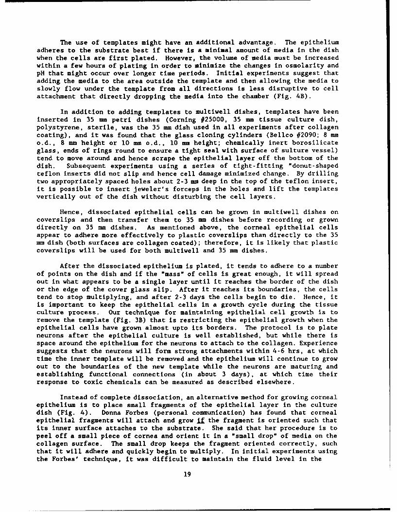
The use of templates might have an additional advantage. The epitheliumadheres to the substrate best if there is a minimal amount of media in the dishwhen the cells are first plated. However, the volume of media must be increasedwithin a few hours of plating in order to minimize the changes in osmolarity andpH that might occur over longer time periods. Initial experiments suggest thatadding the media to the area outside the template and then allowing the media toslowly flow under the template from all directions is less disruptive to cellattachment that directly dropping the media into the chamber (Fig. 4B).
In addition to adding templates to multiwell dishes, templates have beeninserted in 35 mm petri dishes (Corning #25000, 35 mm tissue culture dish,polystyrene, sterile, was the 35 mm dish used in all experiments after collagencoating), and it was found that the glass cloning cylinders (Bellco #2090; 8 mmo.d., 8 mm height or 10 mm o.d., 10 mm height; chemically inert borosilicateglass, ends of rings round to ensure a tight seal with surface of sulture vessel)tend to move around and hence scrape the epithelial layer off the bottom of thedish. Subsequent experiments using a series of tight-fitting "donut-shapedteflon inserts did not slip and hence cell damage minimized change. By drillingtwo appropriately spaced holes about 2-3 mm deep in the top of the teflon insert,it is possible to insert jeweler's forceps in the holes and lift the templatesvertically out of the dish without disturbing the cell layers.
Hence, dissociated epithelial cells can be grown in multiwell dishes oncoverslips and then transfer them to 35 mm dishes before recording or growndirectly on 35 mm dishes. As mentioned above, the corneal epithelial cellsappear to adhere more effectively to plastic coverslips than directly to the 35mm dish (both surfaces are collagen coated); therefore, it is likely that plasticcoverslips will be used for both multiwell and 35 mm dishes.
After the dissociated epithelium is plated, it tends to adhere to a numberof points on the dish and if the "mass" of cells is great enough, it will spreadout in what appears to be a single layer until it reaches the border of the dishor the edge of the cover glass slip. After it reaches its boundaries, the cellstend to stop multiplying, and after 2-3 days the cells begin to die. Hence, itis important to keep the epithelial cells in a growth cycle during the tissueculture process. Our technique for maintaining epithelial cell growth is toremove the template (Fig. 3B) that is restricting the epithelial growth when theepithelial cells have grown almost upto its borders. The protocol is to plateneurons after the epithelial culture is well established, but while there isspace around the epithelium for the neurons to attach to the collagen. Experiencesuggests that the neurons will form strong attachments within 4-6 hrs, at whichtime the inner template will be removed and the epithelium will continue to growout to the boundaries of the new template while the neurons are maturing andestablishing functional connections (in about 3 days), at which time theirresponse to toxic chemicals can be measured as described elsewhere.
Instead of complete dissociation, an alternative method for growing cornealepithelium is to place small fragments of the epithelial layer in the culturedish (Fig. 4). Donna Forbes (personal communication) has found that cornealepithelial fragments will attach and grow if the fragment is oriented such thatits inner surface attaches to the substrate. She said that her procedure is topeel off a small piece of cornea and orient it in a "small drop" of media on thecollagen surface. The small drop keeps the fragment oriented correctly, suchthat it will adhere and quickly begin to multiply. In initial experiments usingthe Forbes' technique, it was difficult to maintain the fluid level in the
19
B ~HP
S• T
D
CS
FIGURE 4. Culturing corneal epithelium. A: Technique for platingfragments of corneal epithelium (FC) into droplets of media (D) placed onpieces of collagen-coated plastic coverslip (CS) which have been placed ina 35 mm petri dish (PD) prior to collagen coating. After a few hours inthe incubator, media is slowly added to the outside of a template (T) ringfrom a hand-held micropipettor (HP) which allows the media to uniformlydistribute itself around the culture dish. B: A side view showing thedroplets of media (D) resting on the cover glass slips and more mediabeing pipetted behind the template (T) and flowing around and under thetemplate to gently cover the bottom of the petri dish.
20

droplet. [The dehydration rate in the laminar flow hood is high. Herexperiments were in Wisconsin and hence her laboratory might be higher inhumidity.I When the fluid level was increased, the fragment tended to float andnot adhere to the dish. To enhance the chances of firm attachment, her protocolcalled for the fragments to remain in small droplets of media for several hoursbefore adding more media. However, in our experiments even after a few hours,there still was a tendency for the fragment to detach when new media was added.
To compensate for these problems, in future experiments each 35 mm dishcontaining droplets of media will be kept in the incubator until an epithelia inthe dish fragment is ready for transfer and then it will quickly be transferredto the hood, the epithelium transferred, and returned to the incubator as quicklyas possible. In addition, the room humidity will be monitored and if low, asterilized ultrasonic humidifier will be used to compensate. These proceduresshould minimize decreases in droplet volume which could cause increases inosmolarity beyond physiological limits. In addition, techniques will be designedto more gently and gradually add media and thus minimize detachment. Thesestrategies including making minichambers in template from which the media wouldslowly flow into the larger chamber and using smaller pipette volumes togradually add the media (Fig. 4B).
Summary
Although co-cultures are currently growing and are being recorded, thetechnique for producing co-cultures requires refinement before reaching acommercial stage: There must be a way (1) to focus the epithelial culture to thearea of the dish to be recorded from, (2) to obtain a uniform epithelial culture,(3) to restrict the area of neuronal plating so that corresponds to theepithelial culture (plate the neurons so that they attach to the area of neurongrowth but not to other areas of the dish), (4) to have a means for theepithelium to continue to grow after the neurons are plated so that theepithelium does not age before the neuronal response is measured, and (5) to havea means for minimizing the number of fibroblasts in the neuronal culture. Asdiscussed above, research in these areas is currently underway and will continueduring the next contract year.
Perfusion System
Before recording, the culture solution (see elsewhere) is replaced withrecording media. Initially, experiments used a Hank's (Sigma) solution with anadditional 10-15 mM HEPES to buffer pH. The cells appeared to respond normallyfor at least 4 hours.
As illustrated in Figure 5, a perfusion system was constructed in whichHank's solution was circulated using a roller pump to control the flow rate. Asecond tube of larger diameter was installed in the roller pump and connected toa second tube which was inserted in the bath. By raising and lowering thesuction tube, it is possible to control the fluid level. In order toelectrically isolate the perfusion system from the recording setup, "dripisolators" are used which isolate the recording setup from ground. Such a systemis currently being evaluated. Currently, experiments are running at roomtemperature. The effects of temperature on physiological response will be testednext year.
21

MR
RP
FIGURE 5. Perfusion system design. The petri dish (PD, 35 mm) containingthe tissue culture (see Figs. 2-4) is placed in a plastic holder that fitsin the base plate of the microscope (see phase I Final Report). The inlet(IL) and outlet (OL) of the perfusion system are positioned as close tothe edges of the petri dish as possible in order to leave room forpressure injection (PI) and recording (R) electrodes. Since the flow ofperfusion fluid is from the inlet toward the outlet, neurons closest tothe... (figure legend is continued on next page)
22

FIGURE 5 continued. ... outlet are recorded from (R) first in order tominimize the possibility that the chemicals released from the pressureinjection pipette (P) can reach neurons that have not yet been studied.Because the tubing from the outlet is larger than that to the inlet andbecause the inlet and outlet tubings are connected to the same roller pump(RP), the maximum rate of flow out of the petri dish is always greaterthan the inlet rate. Hence, the level of media in the dish is controlledby raising or lowering the level of the outlet port with a miniaturizedmanipulator (MI). A similar manipulator regulates the height of the inletport (M2). The fluid flow through the inlet and outlet is electricallyisolated from the tissue culture recording by drip isolators (DI) whichcreate an air gap and thus eliminate ground loops and electrical noisegenerated by the roller pump. The recording media is held in a reservoir(MR) before being sucked into the roller pump. Gas (G) from a pressurizedcylinder is constantly being bubbled into the media. The gas is 100% 02when Hank's solution is used with a HEPES buffer as a recording media andis 95% 02, 5% CO2 when Earle's solution is being used with a bicarbonatebuffer (see text). The exit flow is collected in a waste reservoir (WR).During the second year of the contract (see text), a heating block(aluminum) will be installed to warm the temperature of the recordingmedia before it reaches the petri dish and to directly heat the petridish. The temperature of the media will be feedback controlled to apreset temperature through a thermocouple placed in the tissue culture(not shown).
23

A comparison of neuronal response in Hank's (HEPES) and Earl's(bicarbonate) buffered solutions has shown no significant differences to date.More extensive testing is planned for the coming year.
Data Acguisition and Analysis Software
For phase II development, a new software package was written in acombination of Microsoft, QUICKBASIC, and C-languages. C software allowedmaximal speed of data handling and hardward control, QUICKBASIC is compiled andhence faster than BASIC and has flexibility in menu construction, writingequations and plotting data. The data acquisition system was changed fromKeithley to Metrabyte. The advantage of the Metrabyte system was greater speed.Also, the entire board was on a bus in the computer system, making it less bulkyand easier to manage. The design goal was to be able to sample the membranevoltage at a 10 kHz rate. Sampling at a 10 kHz rate gives a maximum frequencyresponse of 5 kHz which was judged to be adequate for obtaining nondistortedwaveforms of the membrane response to both room temperature and core temperaturepreparations. With the use of C programming, it was possible to control theboard with use of the fast computer system (PC320386, 33 MHz). It was possibleto sample both the stimulus and the membrane response at 10 kHz and the memorylimitations of the computer did not exceed the 100 msec required to record thecell's response to electrical stimuli. On the other hand, sampling for muchlonger time periods was required (up to several minutes) in order to track theresponse of a neuron following chemical exposure. It was found that due to thelimitations of computer memory (640K total) the program could only run for amaximum of 3 sec sampling at the 10 kHz rate. It was decided that alternativestrategies must be explored. First, the possibility of using expanded orextended memory was investigated. However, the EMS controller necessary toaccess expanded memory required too much overhead time to allow sampling at a 10kHz rate. In addition, it was found necessary to sample 3 channelssimultaneously (membrane response, current and pressure waveform). Hence, atotal of 30 kHz needed to be stored for extended periods. An alternative was tostore the data on a digital tape or a VCR recording system and perhaps computercontrol of the tape recorder could be implemented. However, after evaluating theAxon system hardware and software which has the capability of recording directlyonto disk, it was determined that likely our system could exceed thespecifications of the Axon system and could record onto the hard disk using a DOScommand structure.
As shown in Figure 6, the data acquisition software for sampling membranevoltage, pressure injection, and constant current stimuli has three majorcomponents. First is the run option with which the data is collected, second isa review section, and thirdly a backup onto cassette tapes. Each one of thesecomponents will be discussed separately.
I. In the run mode, the computer stores an information file containing somegeneral information about the target tissue and about the neuron culture. Witheach experimental run, the program also stores the protocol being used forstimulation. For example, in the constant current stimulus mode the type ofhyperpolarizing or depolarizing pulse is recorded in the information file alongwith a second file containing the sampled data. For depolarization, both 5 msecand 50 msec duration pulses are used to determine threshold. For suprathreshold,only the wider duration pulse is used looking to determine whether there is
24

0 41% 4 4
v 0 A0
4).
0~0.
41 V)) 2..
4 1- r. 0 r 4
0 02 0 10
4)I r4 VC
-% 4)
00 " 10
>>l 4.)d C
00
0- -u 0 .4Lp! r02 "i -0.0 04W1i2 02 020 02W i 4.>) :
0 U 4 4AnV lb
04: o V 02 0'
cn~~~ C.. 02- I 4l V
F-4 P. " a 4)-o a >.
P4 41 .. 0'-
0 0r.C 0" 4).
00 Icf3~4 I
0 W 144 '0
CA WC ______________________
'-4 ______________________o
ý-4 bo r'-
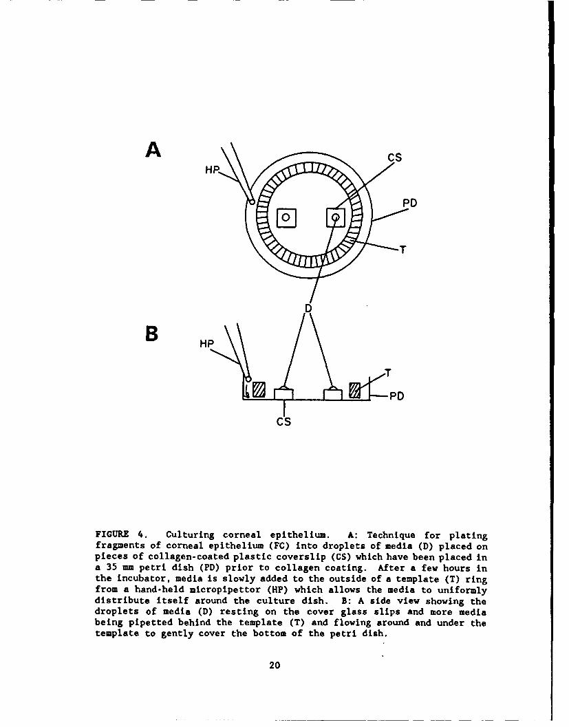
multiple spikes generated by the constant current pulse. For hyperpolarizing,all pulses are 50 msec in duration, and a series of increased voltages are used.For both the current stimulation and L. &e chemical stimulation, pulses aregenerated independently of he computer by a electrical stimulator. A long-termgoal of the project which is beyond the phase II tasks and objectives is toimplement a program with computer control of the stimulation parameters.
II. The review section of the program replots the data and has the abilityto zoom in or out in time to review large segments of data and then magnifysegments of interest, as illustrated in Figure 12. The program can scrollthrough the record and amplify the amplitude of the membrane response or thestimulus waveform. For analysis, a cursor can be placed on the response tomeasure precisely the voltages and the timing of the membrane response. Thereis also a section for curve fitting and determining the parameters of theresponse to the chemical stimuli.
III. Because of the large amount of data digitized, it is necessary to usea large hard disk (80 Mbytes) and to backup the hard disk regularly. A cassettebackup system has been found to be ideal for this purpose, and there are optionsto backup daily, by the month, or by the whole drive.
A "snapshot" capability is being developed so that the data can be reviewedand records and portions of records can be selected for review and printout. Inaddition, a "batch print" capability is being established so that all theselected runs can be printed sequentially, along with the information filesassociated with each run. Formats are currently being developed so that thebatch print can be directly output to a laser quality printout using QUATROPROfor formating the print process. A procedure to quickly analyze cell membranecharacteristics is being implemented. The program was a curve fitting andpattern recognition routine to recognize the important characteristics of thecell response to depolarizing and hyperpolarizing currents.
In addition, an action potential recognition strategy is being investigatedwith which the time between action potentials (interspike interval) can bemeasured and firing frequencies calculated after drug injection. This softwarewill give added tools with which to evaluate the ability of toxic chemicals toexcite sensory neurons in culture. With this additional software, the rate atwhich action potentials are generated over extended periods of time can beanalyzed, as well as changes in membrane potenital.
Because of their length, printouts of software code have not been includedin this Annual Report. Final versions will be included in next year's FinalReport at the end of the contract period, and current listings are available onrequest.
System Integration
Vibration Isolation. The setup is currently located on a solid basementfloor and the microscope rests on a 1/4 inch iron plate which is isolated fromthe experimental table by four tennis balls. This arrangement appears to beadequate for our current working environment; however, a professional vibrationisolation table is recommended for a commercial setup.
26

Micromanipulator Technology. Initially, a Kopf fluid microdrive wasevaluated, but it was unstable, was nonlinear in its movement, and exhibitedhysteresis to forward and backward movement. A Narashige manipulator withmotorized morote control was found to be adequate in its specifications but hadbeen in use for several years and its remote control was not reliable. Therewere reports from other investigators at the Medical Center that Narashige fluiddrives are often not stable (tended to creep over time). A piezoelectricmicrodrive (Burleigh, #6000) is currently being used. It has performed well, itis stable with little or no observable creep, and has high resolution (0.1 Am)over an extended range (>I cm). It has a remote control with a variable speedcontrol and has either programmable steps or continuous movement. The onlysignificant limitation is that it is rather heavy and bulky. As a consequence,it has been difficult to find a base micromanipulator on which to mount it. Amanual Narashige micromanipulator was evaluated, but it was difficult to keep thegear and clamping mechanisms from loosening and it required constant adjustment.A Pryor manual micromanipulator (Stoelting, #55102) was tested, but it did nothave an adequate return spring and could not be adequately adjusted to hold theBurleigh. A Stoelting micromanipulator (MM33, #55133) is currently workingadequately. However, a heavier manipulator such as a Huxley would probably berecommended for a permanent commercial installation of the Burleigh microdrive.For example, Burleigh has recently introduced a specialty microdrive (BurleighInstruments, #PCS-1000) for in vitro recording. Alternatively, there are newmanipulators with a piezo motor with similar specifications and is within thesame price range as the Burley drive, plus it has 3-axes of remote controlmovement which is a significant upgrade from the Burleigh drive (Fine ScientificTools, Marzhauser #25200).
Recording System. A newer model WPI electrometer was installed to provideincreased capacitance compensation. In addition, the shielding between the linkbetween the head stage and the mount to the manipulator were redesigned to reducenoise and ground loops, as well as the mount between the electrode holder and theWPI head stage.
Chemical Delivery
Because the purpose of the system is to assay toxic compounds, a chemicaldelivery system is being designed that will minimize the amount of chemicalhandled by the workers (Fig. 8) and isolate chemical delivered to the cell understudy. As illustrated in Figure 7, using pressure injection technology it ispossible to load micropipettes with small volumes of solution (<1.0 jl) and thenpressure inject minute volumes (picoliters) in the vacinity of the cell understudy.
Chemical Delivery Micro~ipette. In consultation with Dr. Alcayaga, who isan expert in delivery of chemicals with micropressure injection, a standard glass
27
AR• ,-SP
H \-P T
TS'
CPC
CS
C
S D
Sc
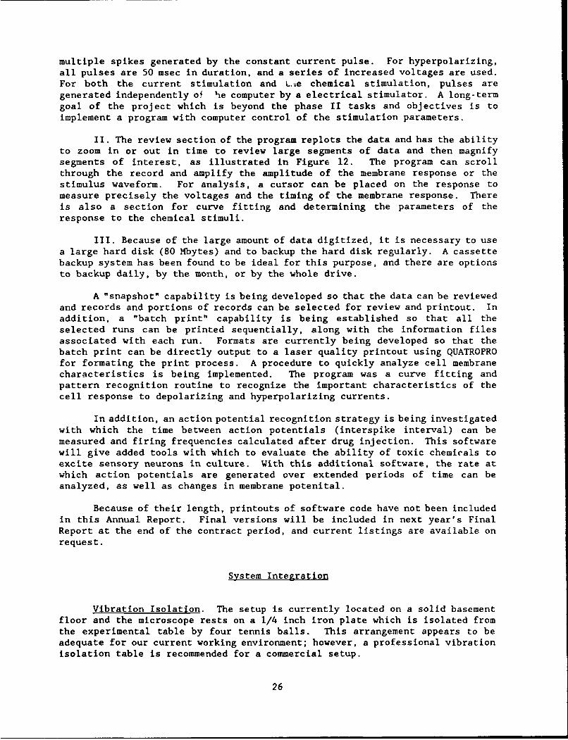
FIGURE 7. Illustration of the chemical delivery technology. Asillustrated in Figure 6B, the pressure injection pipette (P) is mounted ina holder (H) and the sample (S) of test solution is sucked into the tip ofthe pipette using a vacuum pump (VP). The pipette with holder istransferred to the experimental setup, is mounted in a micromanipulator(MM), and under microscopic observation is positioned approximately 100 Amaway from the neuron (N) being recorded (R). A: gives a more detailedview than Figure 6 of the components of the pressure injection hardwareand electronics. The controller is capable to producing either a constantvacuum... (figure legend continued on next page)
28

FIGuRE 7 continued ... through a vacuum pump (VC) and sensitive vacuumregulator (VR) that was specifically fabricated to compensate for fluidleaking from the pipette tip. Leakage can occur due to hydrostaticpressure (see HP in B) or due to increased size of the tip of the pipette(see C). On the other hand, the controller is capable of producing aconstant pressure head through a pressure tank (T2) of inert gas (100% N2)connected to a specially fabricated sensitive regulator with which thecapillary pressure can be compensated. The controller also produces astep pulse and pressure which causes the chemical to be pushed out of thetip of the pipette. This is accomplished through a second gas canister ofinert gas (100% N2) connected to a second regulator and timing of thepressure pulse is controlled by a stimulator (S). The pressure wave fromthe controller is monitored by a pressure transducer (PT) and the signalfrom the transducer is sent to the computer. B: shows a simplifieddiagrammatic sketch of the pressure forces at work during steady state.The capillary pressure tends to suck fluid up into the pipette from thesolution. The amount of capillary pressure is dependent on thecharacteristics of the solvent placed in the microelectrode. On the otherhand, the hydrostatic pressure (HP) is produced by the gravitational pullof the fluid column and tends to push the fluid out of the pipette. C:The amount of leakage out of the pipette is influenced by the tipdiameter. Panel 1 shows a diagrammatic sketch of thin pipette whose tipis almost beyond view of the light microscope level. Such pipette tipswere found to be of a disadvantage for these experiments because of thepressure wave produced by pushing the fluid out of the tip caused amechanical artifact during recording. In addition, the small tips easilyare clogged. The second drawing illustrates a relatively larger pipettetip. Current experiments use a tip about 4-9 Asm in diameter. The tipsare pulled using the Sutter puller which is programmed to produce tips ofuniform diameter. The third example is illustrative of tips of greaterdiameter (12-15 j.m and greater) through which there can be a continualflow of solution. Tactically it is possible to use a tip of largerdiameter and to control the leakage out of the pipette with vacuum and byrecording first from cells closest to the exit of the perfusion system asexplained in Figure 5.
29

capillary was selected of the type used in patch clamp (AM Systems, 1.5 mm o.d.,#7052). The Sutter puller (Sutter Instruments, #P-87) was used to pull tips ofvarious sizes. Unlike the recording electrodes, the tip sizes of micropressureinjection pipettes are within the limits of light microscopy, and hence it ispossible to directly measure dip diameters using a compound microscope with acalibrated micrometer eyepiece (450x). Initially, tip sizes of 0.5-1.5 iLm
internal diameter were used; however, it was found that during pressureinjection, the pressure wave exiting the micropipette was frequently sufficientto mechanically dislodge the recording micropipette from the neuronal cell body.Furthermore, optimal positioning of the pressure injection pipette was examinedin control experiments. It was found that with a small tip not only was the exitvelocity high causing a significant pressure wave, but also the path traveled bythe dye was narrow and hence pressure injection electrode had to be positioneddistantly from the cell being recorded. This issue is important for a commercialassay system because optimal recording efficiency requires that the experimenterbe able to see the outline of the pressure injection pipette while viewing (400x)the cell being injected. If the pressure injection pipette can not be viewedunder high magnification, it cannot be accurately aimed at the cell under studyand a significant amount of time is spent shifting between 400x and 200x toinsure the proper orientation of the electrode. (One cannot switchmagnifications while recording because the mechanical vibration will dislodge therecording pipette from the neuron.] In addition, it is important to be able toview the tip of the pressure injection pipette tip to insure that it has notbecome partially clogged by crystalization or protein buildup.
For these reasons, very small tips were not used. Further experimentationsuggested that tip diameters of 4-8 Am appeared to be more optimal because of (1)minimal tip clogging, (2) a wider envelope of chemical delivery, and (3) a lowerexit velocity such that the force pressure wave reaching the cell was low enoughthat there was no evidence of tissue injury, recording electrode dislodgement,or mechanically induced neuronal activation.
With tips larger than 12-15 gm, there appeared to be significant leakageof chemical from the tip of the pressure injection electrode due to hydrostaticpressure (Fig. 7B). A vacuum line was installed to investigate the possibilityof using back pressure to limit fluid leakage (Fig. 7A), and it was determinedthat vacuum could indeed inhibit leakage. It was decided that the mediumdiameter tips (3-8 Am, Fig. 7C) were adequate to accomplish the goals of thestatement of work and further investigation of larger tip diameters was notnecessary (see Investigation of Multiple Delivery Systems for furtherdiscussion).
Another significant problem was the effect of capillary action. Asdiscussed below (Fig. 8), to maximize safety, minimize contamination and maximizecommercial efficency, only small volumes were loaded into the tips of thechemical delivery pipettes. [Because of the extremely small volumes (picoliters)that are pressure injected from the pipette, fractions of microliters in totalvolume are adequate.] However, because the capillary pipettes are not completelyfilled, there is a negative capillary pressure (Fig. 7B) in aqueous solution thatcauses the stimulus fluid to migrate up the pipette and suck recording media intothe stimulus pipette. This effect causes a significant dilution of stimuluschemical and, more importantly, loads the tip of the pipette with recordingmedia. Hence, it is necessary to create a back pressure to compensate. Ourfabrication consultant built a variable pressure gauge to regulate the back
30

ATL RL RH
AV
MM • PT
H
PD•RM
NCS N
BM M6 R
HP ':
CN
I 2 3
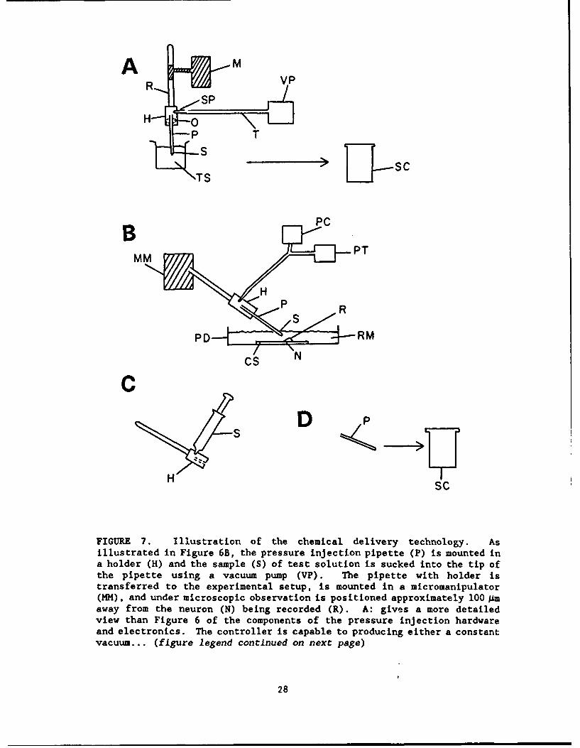
FIGURE 8. Safety procedure for loading and handling pipettes with toxicchemicals. The goal was to perform the pipette loading and disposalprocedures under ventilation hood and to carry only a small volume (<1.0Ml) of solution to the experimental setup. A: shows a manipulator (M)being used to lower the micropipette (P) into the test chemical (TC). Thepressure injection microelectrode is held in a microelectrode holder (EH)which is specifically designed for pressure injection, with an O-ring (0)to form an air-tight seal and a side port (SP)... (figure legend continuedon next page)
31
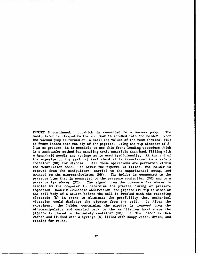
FIGURE 8 continued. ... which is connected to a vacuum pump. Themanipulator is clamped to the rod that is screwed into the holder. Whenthe vacuum pump is turned on, a small (S) volume of the test chemical (TS)is front loaded into the tip of the pipette. Using the tip diameter of 2-3 ;Am or greater, it is possible to use this front loading procedure whichis a much safer method for handling toxic materials than back filling witha hand-held needle and syringe as is used traditionally. At the end ofthe experiment, the residual test chemical is transferred to a safetycontainer (SC) for disposal. All these operations are performed withinthe ventilation hood. B: After the pipette is filled, the holder isremoved from the manipulator, carried to the experimental setup, andmounted on the micromanipulator (MM). The holder is connected to thepressure line that is connected to the pressure controller (PC) and to apressure transducer (PT). The signal from the pressure transducer issampled by the computer to determine the precise timing of pressureinjection. Under microscopic observation, the pipette (P) tip is aimed atthe cell body of a neuron before the cell is impaled with the recordingelectrode (R) in order to eliminate the possibility that mechanicalvibration would dislodge the pipette from the cell. C: After theexperiment, the holder containing the pipette is removed from themicromanipulator and carried back to the ventilation hood where thepipette is placed in the safety container (SC). D: The holder is thenwashed and flushed with a syringe (S) filled with soapy water, dried, andreadied for reuse.
32

pressure necessary to inhibit the capillary filling (Fig. 7A). The influence oftip diameter on back pressure is currently being investigated.
The pressure injection protocol follows that established by our consultant,Dr. Alcayaga, for use in studying the response of chemosensitive nodose ganglionneurons which had been grown in co-culture with chemosensory (i.e., glomus) cellsfrom the carotid body. In this protocol, a pressure injection wave 500 ms induration was pulsed at a 0.5 Hz rate for 2-5 repetitions and the response of theneuron monitored. A pressure has been installed to monitor the timing of thepressure injection pulse (see Figs. 9-21 which illustrate the effects of pressureinjection of test chemicals).
Pipette Loading and Safety Procedures. As illustrated in Figure 8, achemical delivery system has been designed which minimizes exposure to toxicagents. Using pipettes with tip diameters >3 jAm has an advantage in addition tothose discussed elsewhere that it is possible to suck solutions into the pipetteinstead of back filling with a syringe attached to a long needle, as is donetraditionally. Our consultant, Dr. Alcayaga, advised that using pipettescontaining filaments was not advantageous for pressure injection because althoughthe filament added in filling, it also produced an uneven flow of solution outof the tip during pressure injection.
The protocol (Fig. 8) is to pull a pipette, verify that it is properdiameter microscopically, insert the pressure injection pipette into acommercially available pipette loader with an air tight O-ring seal. The pipetteplus holder is then moved to the hood which contains the solution of toxicchemical and is attached to a micromanipulator. The pipette is then lowered downinto a microcentrifuge cup containing the stimulus solution, attach a tube fromthe electrode holder to a vacuum pump, and suck the stimulus solution into thetip of the pipette.
The pipette holder is then transported to the tissue culture recordingsetup, mounted to a manual micromanipulator, and attached to the pressureinjection hardware (Fig. 7). The pipette is gradually lowered intothe solutionunder microscopic observation until it is pointed at the center of themicroscopic field, about 60-100 Am from the bottom of the petri dish. The baseof the microscope is then moved to position a neuron for study. The neuron isimpaled with the recording microelectrode. Because the pressure injectionpipette does not actually touch the surface of the cell, it is not necessary touse a micropositioner with remote control. Instead, a relatively inexpensivemanipulator (see above) is adequate.
Multiple Chemical Delivery. As part of the general task of investigatingdelivery systems, the possibility of designing a multiple injection pipette wasinvestigated. These experiments were completed by Dr. Tuckett in associationwith consultant, Dr. L. Monti, who is an expert on chemical delivery to olfactoryand carotid body chemosensory neurons. One possibility was to pull a multibarrelglass micropipette. The critical issues here are: (1) obtaining a reproducibleand uniform tip diameter, and (2) being able to efficiently attach the exit endof each barrel to a pressure line so that each barrel could be independentlyinjected. It was found that the Sutter puller was not well suited for pullinga multibarrel pipette because the heating filament was open on top and hence didnot provide uniform heating of each barrel. A Kopf puller was tested; however,the clamp that holds the ends of the glass capillaries did not apply a uniform,symmetrical pressure to all the individual pipette barrels and hence crushed the
33

glass. In contrast, a verticle Narashige puller was more promising because theclamp that holds the pipette ends is a screw mechanism that applies uniformpressure. After a padding material was inserted to uniformly distribute thepressure from the clamp, it was possible to pull multibarrel pipettes with auniform tip diameter (500x). It was concluded that with proper modification,multibarrel pipettes could be pulled for micropressure injection. To connect theindividual pipette barrels to the high pressure line, it was discovered that theultrafine disposable pipette tips that are currently available for hand-heldmicropipettors fit into the capillary glass and can be quickly attached usingsuperglue for an air-tight seal.
Alternatively, it was found that ultra fine disposable pipette tips usedwith micropipettors are uniformly manufactured with inside tip diameter of about150 1m. Hence, if sufficient vaccuum can be applied to keep the fluid frommigrating out of the pipette tip, it might be possible to glue several tipstogether, cut them so that they are precisely the same length, load themindividually, and use them as a multiple delivery system.
As a third alternative, the possibility of using separately mountedindividual pipettes was investigated. Our fabrication consultant (Mr. Evans)built a dual holder that would mount two delivery pipettes on onemicromanipulator. The holder was capable of changing the height and angle of theindividual pressure injection pipette independently. However, it was discoveredthat the angle and the distance between the two (fragile) pipette tips wasextremely difficult to align. Hence, this alternative did not seem practical forcommercial application.
Another alternative is to mount the individual pipettes on independentmanipulator systems. Although this technique is feasible, it might beimpractical because of the difficulty in repositioning the pressure injectionelectrodes while recording from the cell without creating enough vibration toinjure the cell. Also, it would be physically difficult to position severalmicromanipulators around the 35 mm petri dish used for recording.
In summary, the two most practical methods of multiple delivery are likelyto be a multibarrel approach either using a multibarrle electrode with a modifiedvertical puller, or by using ultrafine pipette tips. Because it was possible toaccomplish the statement of work of this project without a multiple deliverysystem, we focused our efforts in other directions.
Data Collection
Voltage Clamp
A series of experiments were performed with our consultant, Dr. E. Lasater,on the feasibility of using voltage clamp techniques to record from the neuronsin culture. Our objective was to determine whether it was technically feasibleto obtain a high impedance seal between the cell and the suction electrode.Initially obtaining a good seal was difficult. Under Hoffman optics, the surfaceof the cell bodies appeared to be irregular with ridges and valleys. Several tipsizes were tested on the suction pipettes using different types of glass (Sutter,WPI), and various shapes of tips as modified by flame polishing the under amicroforge. Although these modifications produced an improved high impedance
34
seal, there was still significant leakage current. Slightly (<51) decreasing theosmolarity of the recording media caused the neuronal cell body to swellslightly. Under the Hoffman optics (200-400x), some areas of the cell bodysurface appeared to be more smooth in appearance and patching these areasproduced a significant improvement in seal; and as a result, fast changes involtage-current relationships could be monitored.
In conclusion, two important technical limitations of voltage clamp weretested: (1) whether a high impedance seal (gigaohm) could be obtained, and (2)whether the cell body could be adequately clamped. In some neural systems, thesize and geometry, axonal or dendritic processes do not allow the whole cell tobe voltage clamped. In such cases, since the voltage cannot be controlled, thecurrents cannot be accurately studied. These experiments suggest voltage clampstudies are technically feasible in the assay system.
Current Clamp
Initially the focus has been on intracellular recording because thetechnique produces a significantly higher yield and is technically less demandingthan voltage clamp techniques. For example, an employee of Topical Testing witha B.A. degree was trained within a few weeks to record intracellularly. Incontrast, to use voltage clamp will probably require a doctoral level employee.In addition, the voltage clamp technique is more tedious. In patch clamp, theelectrode must be changed each time it touches a cell surface. Hence, asignificant amount of time is required to change electrodes. [In contrast, asingle intracellular electrode can often be used for several current-clamprecordings. Each time a new recording electrode is used, several minutes arerequired to position the electrode near the cell under high magnification. Inaddition, the manufacture of patch clamp electrodes is time consuming because inmost preparations they must be polished in a microforge. In contrast,intracellular pipettes can be used immediately after fabrication.]
On the other hand, voltage clamp can be used to study membrane currents indetail and hence document ion channel mechanisms.
Response to Chemical Stimuli
The following figures illustrate the response of neurons in culture tochemical stimuli. The fundamental hypothesis to be tested during the contractperiod is whether co-cultured neurons are chemosensitive and will respond toendogenous and exogenous irritant and pair-producing stimuli. Hence, thecultures have been surveyed with a number of chemical species at high doses ofchemicals.
Control Stimuli. Initially, neurons were tested with vehicles that arelikely to be used in subsequent experiments. The neurons were found to beunresponsive to distilled water (Fig. 9), polyethylene glycol (Fig. 10), anonionic hyperosmotic solution of 10% sucrose (Fig. 11), saline, and recordingmedia.
Painful. Irritant and Toxic Stimuli. Neurons were found to be reactive tobradykinin (Fig. 12), capsaicin (Fig. 13: a classical pain-producing substancefound in hot peppers), serotonin (Fig. 14), histamine (Fig. 15), and sodiumcyanide (Fig. 16).
35

Acidic and Basic Solutions. Neurons were responsive to acetic (Fig. 17)and hydrochloric (Fig. 18) acid as well as to Hank's solution whose pH had beenshifted to 4.9. At the other extreme, neurons were responsive to Hank's solutionat pH 11.6 (Fig. 20) and sodium hydroxide (Fig. 21).
Results to date have shown that not all neurons that hay been recorded fromare chemosensitive. This result is expected, since trigeminal neurons innervatea wide variety of tissues and supply neurons which are known to not bechemosensory, such as mechanoreceptive neurons. On the other hand, as shown inFigures 12-21, a substantial number of neurons recorded in culture have beenchemosensitive and have reacted to a number of endogenous and exogenoussubstances known to produce pain and irritation as well as to shifts of pH thatare known to be irritant.
Next year's research will focus on determining the classes of toxiccompounds to which the neuronal assay is specifically reactive, whether responsespecificity is altered when the neurons are grown with corneal epithelium, andwhether response specificity changes as the neurons are maintained for longertime periods in culture.
36

49.0
-80.!
S it(jRESSUR
-:23:3:
FIGURE 9. Stimulation with distilled water (control experiment). Plotshows a lack of response of the neuron during and after pressure injectionof distilled water using the micropipette technology discussed above. Theplot is typical of the plots in the following figures (Figs. 10-21). Thetop trace shows the membrane voltage and the left-hand axis (Y axis) isscaled in millivolts from +80 - -80 my. The X axis is time extending from0 to 5 sec. The bottom trace shows the timing of the pressure injectionas monitored with a pressure transducer in the line (see Figs. 7 and 8 fordetails). In Figures 9-11 and in some other experiments (which will beexplicitly designated), simultaneous with the start of each pressure wave(which usually lasted about 500 msec) a suprathreshold constant currentstimulus pulse (50 ms) was generated which created a depolarization of themembrane potential. Hence, a membrane depolarization can be seenimmediately before each pressure wave. This added stimulus was used todetermine whether the chemical stimulus was producing a consistent changein the sodium channel activation of the neuron's membrane. The bottomtrace is the pressure wave which is uncalibrated and merely shows thetiming of each pressure stimulus. A series of 5 pressure pulses andelectrical stimuli were given. There was no consistent change in theresting membrane potential or on its response to current stimulation.Hence, it was concluded that distilled water had no significant effect onthe response of the neuron.
37

40.0
-40.9
FIGURE 10. Stimulation with polyethylene glycol (control experiment).The stimulation procedure was as in Figure 9 with an identical time periodof 5 sec of sampling during which three pressure waves and threeelectrical pulses were generated. Note that the polyethylene glycol hadlittle or no effect on resting membrane potential or on sodium channelactivation with the depolarizing electrical pulse.
38

80.0
40..0
-0.0 -------------- ........
4 ti. (PRSSURE)
0.0 . ...................................... : : .... , . ...............
-4,
FIGURE 11. Stimulation with 10% sucrose (control experiment). Thestimulation procedure and figure scaling are as shown in Figure 9. Note
that the pressure injection of the high molarity solution had little or noeffect on the neuronal response. This result suggests that thepresentation of a high molarity solution (in and of itself) has littleinfluence on the neuron's response characteristics.
39

A
-49,
-40, e-
-2 e .. .. .. ............. ....
-4,e.
-2e.0
-4,
FIGURE 12. Stimulation with bradykinin (9.3 mM) in saline. A: Scaling isas In previous figures; however, the time course was for a longer periodof 0-50 sec rather than 0-5 see as in the previous figures. Note thecontinued responsiveness of the neuron to bradykinin. Due to the slowtime base, the individual action potential firings are not seen in panelA. B: An expanded time scale of the stimulation of the portion of therecording in panel A from 0-1.2 sec. Note the multiple firings of theneuron following bradykinin administration (figure legend Is continued onnext page).
40

CI
C 89).
40.0
0.8 ... .. ................... .... ".... ........ "............. •..........-'.
-80.0
0:9 ee -nas_
FIGURE 12 continued. C: shows the response of a neuron from a differentculture to the same concentration of bradykinin.
41

49..9-40.0
40.
9.9 ... ............... .........
-2.3
FIGURE 13. Stimulation with capsaicin. Stimulation is as in Figures 9-11in that a constant current depolarization pulse was given at the first ofthe pressure wave and can be seen as the depolarization at the initialpart of the pressure wave. It can be noted that there was no significantalteration in the sodium channel activation that can be seen with theelectrical current. However, the capsaicin produced a significantreaction of the sensory neuron following the chemical injection.
42

48.0
.40,.
M.(RESSURE)
-3. . -4__ _ _I-2.0
FIGURE 14. Stimulation with serotonin. Shows response of the a neuron in
co-culture with corneal epithelium to serotonin (10.3 mM) dissolved in
Earl's solution.
43
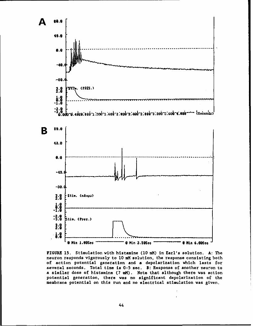
4 .0 - --01---'" ".,* ... ........................ ........
-40. 4
-80 Ii
. r8 ..... ......... .................. ,,. ...........-2. - .-3.0
% ~.~96IO&~.~6&2 ~'- Secods)l
B 89.0
4a.8
3 StiN. n•APS)
1.e
-2.*0-3.9 Stim. (Pres.)
0 Min L1,9Sec 0 Min 3.50Sec " fin 6.IOSec
FIGURE 15. Stimulation with histamine (10 mM) in Earl's solution. A: Theneuron responds vigorously to 10 mM solution, the response consisting bothof action potential generation and a depolarization which lasts forseveral seconds. Total time is 0-5 sec. B: Response of another neuron toa similar dose of histamine (7 mK). Note that although there was action
potential generation, there was no significant depolarization of the
membrane potential on this run and no electrical stimulation was given.
44
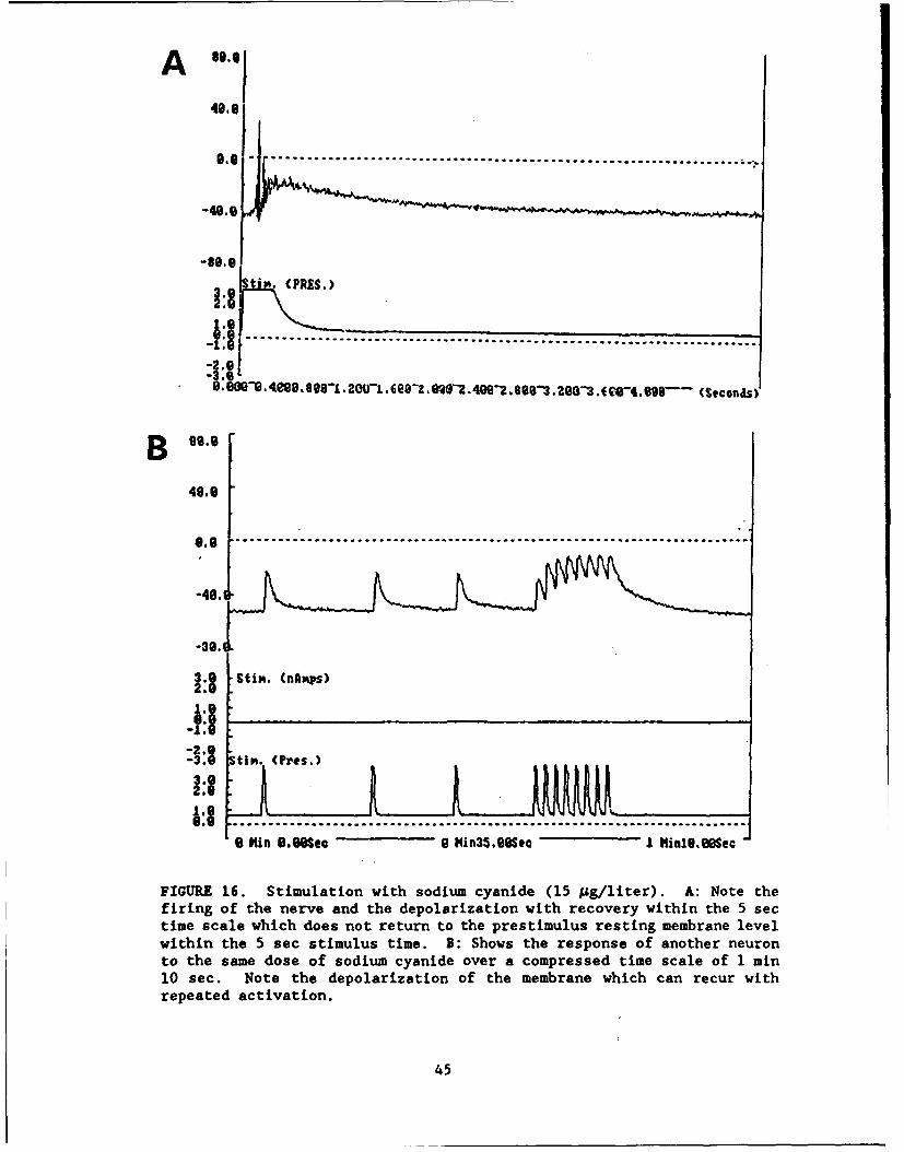
A
..............................................
(PRES.
30-e. :8 O9S4eeB. 8001-ae1.Ji .6ee-2. .eS-.4Oee2. .88O3. zee3 t w4. ese (seconas)
49.0
-10.0 ....................................................... --............. :......
-48.-3.O
-2 .0-3.0 itin. (Pros.)
2:1 L: --- -9 Min ,O.Mea 0 1hin35,eesec I hlifle,•sec
FIGURE 16. Stimulation with sodium cyanide (15 Mg/liter). A: Note thefiring of the nerve and the depolarization with recovery within the 5 sectime scale which does not return to the prestimulus resting membrane levelwithin the 5 sec stimulus time. B: Shows the response of another neuronto the same dose of sodium cyanide over a compressed time scale of 1 min10 sec. Note the depolarization of the membrane which can recur withrepeated activation.
45

A 8.
4,.,
.. .... .... ... ....... .... ..........
-86.|L
$tin. (PRESSURE)
-2,* .
. .. . . . . .. . . . . . .. . . . . . ......... . . . . . . . . . .49.9~ 1 Scns
-49.l
StM PRESSU 7>
....... ......... ......... ......
FIGURE 17. Acetic acid stimulation. Shows the response to increasedconcentrations. A: Response to 1 mn acetic acid. Note that as in Figures9-12, a 50 ms constant current pulse was passed at the start of eachpressure injection (as can be seen by the depolarization of membranepotential at the beginning of the pressure wave). The neuron wasrelatively sensitive to 1 mM acetic acid (repeated firing) but exhibitedno significant membrane depolarization. B: Shows a response of anotherneuron from the same culture which was less sensitive than the previousunit to a higher dose of acetic acid (10 mM) (figure legend continued onnext page).
46

40.9
0.0 ......................
(PMfSURE)-•~~~~~ 4\"J"•'"'-
,:2
S l ............ .... ... .. ................................................
0.0 ..................... ... .................. ..2 ".................. I......-2..•
B. -0. 4&988h263-1 :69-i :Wk,: 2:404-2: 694-3 '24-604, EWC 9 ' Seons
FIGURE 17 contlnued. C and D: Show the response of two different neuronsto 100 am acetic acid. In both instances there is not only firing of theneuron but also a significant depolarization. Hence, these initial datasuggest that as the pH is lowered, acetic acid produces not only repeatedfiring of the neuron but also significant membrane depolarization.
47

98.8
49.9
.6 .. . . .................. ............
1.9""3 .. (PRE$.
-2.9-3.8
FIGURE 18. Stimulation with hydrochloric acid (1 mM). The record showsthe sensitivity of this neuron to exposure to hydrochloric acid andrepeated firing of the neuron following exposure. Note that thedepolarization of the neuron was not significant.
48

A so.,
43.0
-.0:. ............................ .... ........... .... -- - --410A
3 (PRES.)
-2.e
-3.0Qeg htiCecn's)
B 98,9
40.9
:II 't. (PRES.)
-2.0
FIGURE 19. Stimulation with Hank's solution at pH 4.9. Panels A and Bcontrast the responsiveness to neurons from the same culture dish to thesame stimulus. Note the difference in sensitivity of the two neurons tothe same stimulus.
49
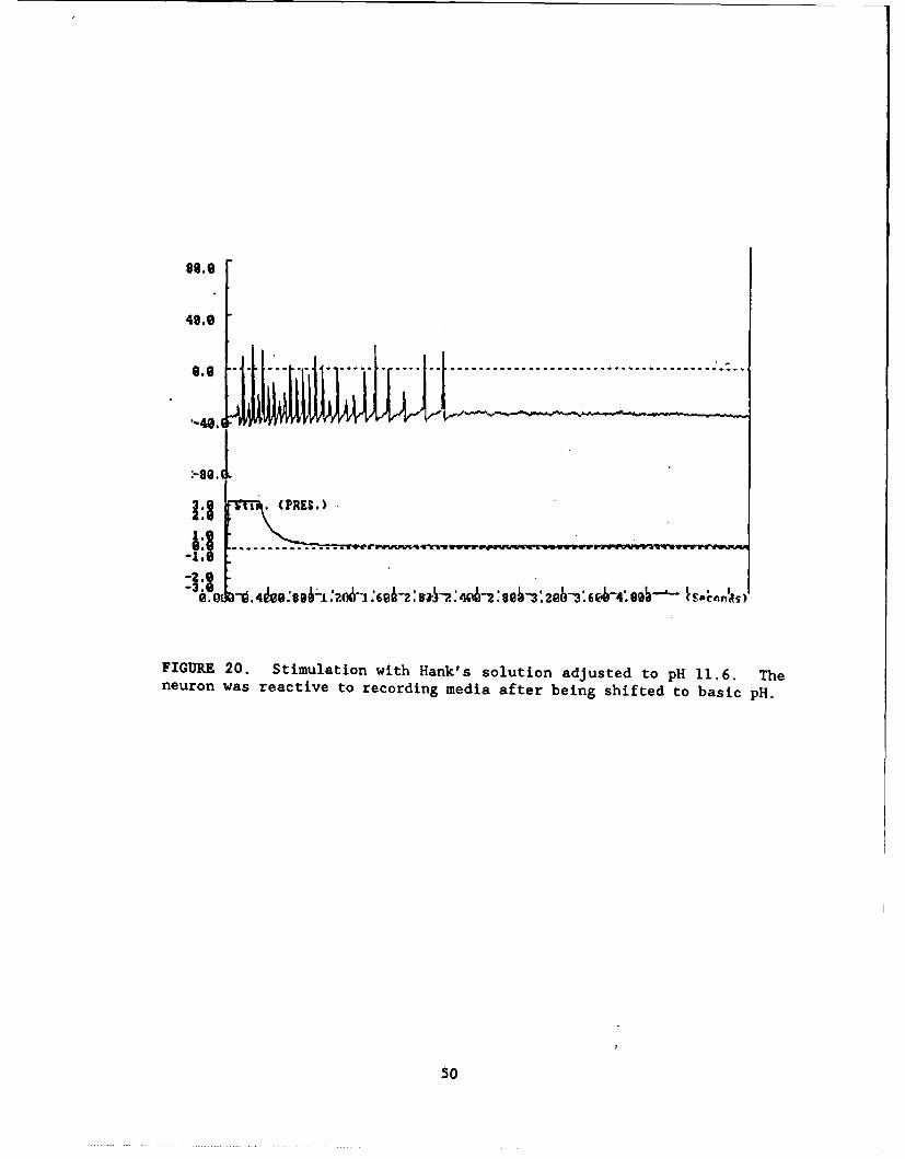
89.9
49.9 ..........................................'-40.1•
:-PRE,!
-2.9
-3. @
FIGURE 20. Stimulation with Hank's solution adjusted to pH 11.6. Theneuron was reactive to recording media after being shifted to basic pH.
50

A s~
48.9
-49. L i ul
-:8.
S........................... ......................... . ..... -=. o".. =.... ... :.. ,
stiiq. (PreT
-------------- .---- ...........................
3.0-1 PH iA45.89S2C S 1Min4?.MSSec 9 HinO.E00Sec
B 80.9
49.0
e.0 -- ........................ .........
-491 IV L.r2U b. IU
-2,* S-3.01
9. PHinl.9seeSec 11inl2,sUec 0 HinlSO9Sec
FIGURE 21. Stimulation with sodium hydroxide. A and B: show response ofneuron to 1 mM sodium hydroxide in two different units. Note the greatersensitivity of neuron in A to the exposure to the basic solution (figurelegend continued on next page).
51
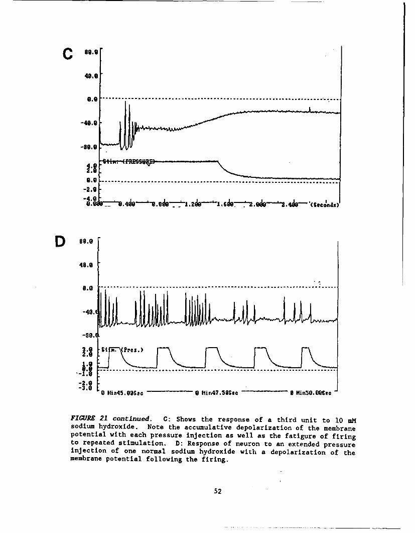
C 9.9
-40.0
-80.0
-2.9
-4.
.0 1x450 92SQi 9 lr4 'ScBNi5.Seons
48.0
9o0 -........ ....... .................... ....---..... . .. .... ........ ..... +......
-80. 1iA L1
FIGURE 21 continued. C: Shows the response of a third unit to 10 mMsodium hydroxide. Note the accumulative depolarization of the membranepotential with each pressure injection as well as the fatigure of firingto repeated stimulation. D: Response of neuron to an extended pressureinjection of one normal sodium hydroxide with a depolarization of themembrane potential following the firing.
52

PROGRESS TOWARDS ACHIEVING THE SPECIFIC OBJECTIVES
During the first year, substantial progress has been made towardestablishing a working assay system. Focus has been on the technical problemsin the experimental setup, on the complexities of establishing a consistent,reproducible co-culture, and on delivery of endogenous and/or irritant chemicalstimuli. More specifically, emphasis has been on obtaining: (1) mechanical and(2) electrical stability, (3) digitization and (4) data collection, (5) chemicaldelivery, and (6) tissue culture reproducibility. The details of these effortsare described in the preceding section (see Progress to Date). The types ofchemical stimuli used during this time period have focused on endogenoussubstances, most of which are known to produce pain and irritation as well assome general irritant stimuli such as acidic and basic solutions.
A summary of progress towards specific objectives is outlined below, aswell as the tasks to be completed in the coming year. The GANTT chart in TableII above shows the originally anticipated work schedule. The first GANTT chartin the next subsection (Table II) summarizes the work completed to date. Theanticipated work schedule for the coming year is given in Table III.
1. Selection of a standard pollution stimulus. Because of the variety ofchemical species that have been applied to the rabbit eye in the Draizetest, the experimental strategy of this contract is to apply chemicalsfrom a variety of chemical families to determine the specificity ofresponse and relate the specificity to previous in vivo test results.During the first year, a variety of chemical stimuli have been applied,including endogenous substances such as histamine and bradykinin,serotonin, etc., as well as extremes in pH and the classical pain-producing substance, capsaicin. During the next year, focus will be onthe application of toxic chemical species to the in vitro system anddocument the differences in response characteristics.
2. Develop a perfusion system which can rinse away the chemical stimulus inbetween stimuli. As discussed above (see Progress to Date), the perfusionsystem has been implemented as well as a means for cleaning of theperfusion pathway.
3. Evaluate how long cultures must grow before testing. It has been foundthat the neurons require 2 1/2 to 3 days in culture before they begin toexhibit normal membrane characteristics. After 5-6 days, some neurons inculture begin to die. Initial observations suggest that there may beincreased specialization in neuronal chemosensitivity of the cells thatremain in culture. Hence, the working hypothesis is that specializationoccurs as neurons continue to grow in culture for longer periods. Thedata gathered in the coming year should help in testing this hypothesis.
4. Evaluate different data acquisition systems to determine which best suitscurrent application. Data acquisition systems and computer systems havebeen evaluated and a optimal system has been configured for ourapplication. Hence, this task is essentially complete.
5. Continue development of action potential recognition and data summarysoftware. At this point in time the most essential elements of the dataacquisition software have been implemented. Up to three channels can be
53

simultaneously sampled at 10 KHz rate and the data can be directly storedon hard disk using a PC computer (20386, 33 MHz, with co-processor andhard disk with <20 ms random access time). Hence the neuron's response,electrical stimulus and pressure wave that signals the timing of chemicalinjection of chemicals can be simultaneously sampled. Consequently, theassay system is capable of recording as many minutes as necessary of themembrane potential and stimulus waveforms online and in real time. Thegains in efficiency over storing on tape for later analysis aresignificant. The data is efficiently packed, and a backup system whichuses cassette tapes (120 Mbyte) is working efficiently. Software forautomated action potential recognition (and frequency of neural firing)after chemical injection is currently being implemented. It isanticipated that the software systems will continually evolve and improveduring the coming year. Specifically, target areas include: (1) thecompletion of the automatic action potential recognition and interspikeinterval calculation software, (2) improve techniques for obtainingpublication-ready data plots on the laser printer, (3) more efficientoperation of software for calculating membrane properties, and (4) database management strategies for organizing and statistically testing thepopulations of experimental data. Hence, task #5 will continue throughoutthe contract period but at a lower level than during the first year.
6. Make improvements in the total integrated system. The total assay systemis complex, and many changes have been made that have improved systemperformance. Focus has been on design of the chemical delivery system,and a preliminary analysis has been made of the feasibility of amultidelivery system (see Progress to Date). Although minor changes willcontinue to be made, the level of effort in this area will besignificantly reduced during the coming year.
7. Evaluate current clamp, voltage clamp and fluorescent technologies. Thecurrent clamp technique is the standard assay used for analyzing membraneproperties of the neurons in culture. As explained above, constantcurrent can produce reliable data with with which to reach the goals ofthis contract. During the first year, a feasibility study on the use ofvoltage clamp proved to be favorable. The data suggests that it will beto obtain patch-quality recordings on the surface of the trigeminalneurons in culture and that the voltage clamp electronics will be able toclamp the neuronal processes in culture so that accurate measurements ofmembrane current will be possible (see Progress to Date). These data alsosuggest that using patch clamp technology to obtain recordings from singlemembrane channels will also be feasible. Hence, the proposed evaluationof voltage clamp recording is essentially complete. An investigation offluorescent technologies will be performed during the coming year.
8. Determine whether cell inhibitor(s) significantly influence thequalitative response to the chemical stimulus in co-culture. This task isgenerally related to the issue of isolation of the neurons fromfibroblasts so that a more pure co-culture of neurons and epithelium canbe obtained. There are three strategies which are being investigated tolimit fibroblast proliferation: [1] As described above (see Progress toDate), it has been discovered that the keratinocyte growth medium has asignificant inhibitory affect on fibroblast proliferation, while at thesame time promoting epithelial proliferation. [2] It has been found thatthe neurons can be separated from the fibroblasts by preplating on plastic
54

Jto which the fibroblasts adhera quickly and then replating the neurons(i.e., a differential adhesion technique). (3] It may be necessary to adda cell inhibitor for a short period of time. For example, evidence nowsuggests that neurons added an established epithelial culture might notestablish a firm contact with substrate and hence may be more difficult toimpale and record from. Hence, the temporary addition of a cell inhibitorto the neuronal culture may be necessary to limit fibroblast and/orepithelial proliferation while neurons are establishing contact with thecollagen substrate. It is anticipated that this task will be completedwithin the first six months of the coming year.
9. Determine whether cell density qualitatively affects chemical stimulusresponse. This task has not yet begun but will be completed during thesecond year (see Table III).
10. Determine whether the buffer system significantly influences thequalitative response to chemical stimulus. Comparison of neurons recordedfrom HEPES and bicarbonate buffer systems has shown no significantdifferences in response to date. More experiments will focus on thisissue in the coming year.
11. Determine whether perfusion solution temperature qualitatively influencesresponse to the chemical stimulus. To date, the experiment have beenconducted at room temperature. Influence of temperature on neuronalresponse characteristics will be tested in the second year of thecontract.
12. Determine whether rabbit neurons have a qualitatively similar response asrat neurons. This objective will be reached during the second year of thecontract.
55
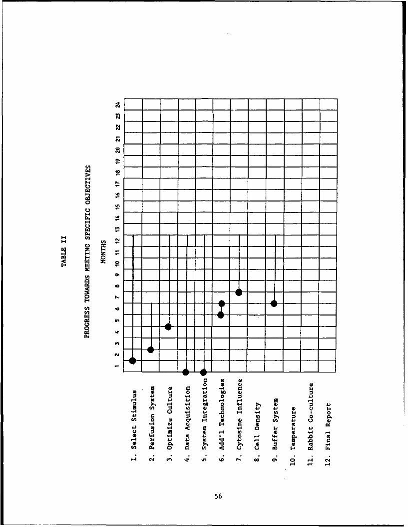
WN
00
.14 -. N1U4 0 -o 0:
'00
00
"-4 ) C
1-4 04"
4:4$ -6 d 0 t4 4
I-. 04cnA .
-4 -- -4
a56
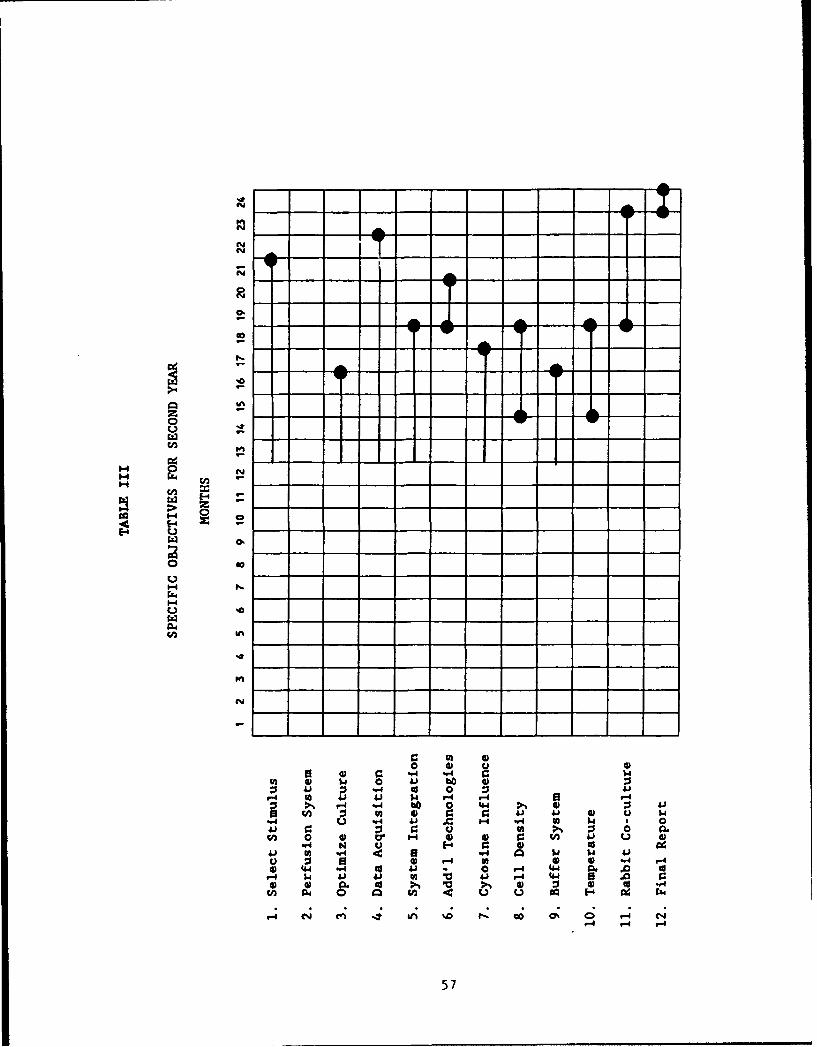
I Tz40.
C3
0'
-v -v
""4 04 N
r-4 N4 b 4 ):
u -P C 0U 0 H '4) 4)
4J In '-4 0 44) 02 .4iM J4 1 -4 0 -4cj- $4~ 41 ,41 VA 0 444 ~ 0
0 0 c J 4) 0 U ."CA P4 .,.4 4cog14 "4 2 1.
".44 N- U 44
4.' 02 .. u ~ U ..4 Q $ $57.

PUBLICATIONS
A manuscript is being planned which will be submitted to an appropriatetoxicology journal describing the physiological response of our assay system.We plan to test with examples from a number of specific categories of toxicchemicals and hence obtain data on response specificity.
58

PROFESSIONAL PERSONNEL
Tovical Testing Personnel
Dr. Robert P. Tuckett Director of Research
Mr. John H. Fisher Electronics Specialist
Mr. Scott Murphy, B.S. Computer Specialist
Ms. Susan Roberts Senior Technician/Tissue Culture Specialist
Mr. Shawn Carlyle, B.A. Junior Technician worked recording from tissueculture during development stage
Emoloyees Through Subcontract At University of Utah
Dr. Julio Alcayaga Research Associate, worked through subcontractwith University of Utah in 1991. He helped withthe design of the experimental setup and initialstrategies of neural recording and chemicaldelivery
Dr. H. Martin Research Associate, is working through Universityof Utah subcontract in 1991. He has providedexpertise on response of nociceptive neurons tochemical stimuli
Dr. Jaime Eugenin Research Associate, working through subcontractwith University of Utah. He is currentlyevaluating response of neurons to irritant andtoxic chemicals
Consultants xets
Mr. Barry Evans Fabrication and design
Dr. John L. Walker Ionic solutions and membrane channels
Dr. Eric M. Lasater Voltage clamp
Dr. Luis Monti-Bloch Chemical delivery
Dr. Dana K. Vaughan Histology
Dr. Kathleen B. English Histology and culturing epithelium
59

INTERACTIONS
Conferences and Presentations
University of Utah Eye Institute, Clinical Conference, May 10, 1991.
Presentation title: "Response of Trigeminal Neurons to Irritant Stimuli"
Interactions with Air Force Laboratories
Dr. Tuckett met with Dr. Channel and Mr. Del Raso on June 24, 1991. Theexperimental protocol and strategy were reviewed, and demonstrations wereconducted in the laboratory and tissue culture areas in the subcontractedspace at the University of Utah, Department of Physiology.
A trip to Wright Patterson is planned for the near future (February orMarch, 1992).
60

PATENTS AND INVENTIONS
A patent on the technology described herein was applied for last spring andDD Form 882 was submitted to our ACO on November 14, 1991.
61