ad-a239 045 repair, evaluation, maintenance, …dtic.mil/dtic/tr/fulltext/u2/a239045.pdf · ad-a239...
TRANSCRIPT
AD-A239 045 REPAIR, EVALUATION, MAINTENANCE, AND
'REHABILITATION RESEARCH PROGRAM
TECHNICAL REPORT REMR-HY-8
__ __ _SHALLOW-DRAFT TRAINING STRUCTURECURRENT REPAIR PRACTICES AND REPAIR
GUIDELINES
by
David L. Derrick
Hydraulics Laboratory
DEPARTMENT OF THE ARMYWaterways Experiment Station, Corps of Engineers
3909 Halls Ferry Road, Vicksburg, Mississippi 39180-6199
n April 1991
Final Report
Approved For Public Release; Distribution Unlimited
91-06107
Prepared for DEPARTMENT OF THE ARMYUS Army Corps of Engineers
Washington, DC 20314-1000
Under Civil Works Research Work Unit 32324
The following two letters used as part of the number designating technical reports of research published under theRepair, Evaluation. Maintenance, and Rehabilitation (REMR) Research Program identify the problem area under whichthe report was prepared:
Problem Area Problem AreaCS Concrete and Steel Structures EM Electrical and MechanicalGT Geotechnical El Environmental ImpactsHY Hydraulics OM Operations Management
CO Coastal
Destroy this report when no longer needed. Do not returnit to the originator.
The findings In this report are not to be construed as an officialDepartment of the Army position unless so designated
by other other authorized documents.
The contents of this report are not to be used foradvertising, publication, or promotional purposes.Citation of trade names does not constitute anofficial endorsement or approval of the use of such
commercial products.
COVER PHOTOS:TOP - Ajax Bar Dikes, Mississippi River,
US Army Engineer District, Vicksburg
BOTTOM - Classroom scene
Form ApprovedREPORT DOCUMENTATION PAGE OMB No. 0704-0188
Public reporting burden for this -ollection of information is estimated to average I hour per response. including the time for revewing instruclons. searching existing data sources,gathering and maintaining the data needed, and compieting and reviewing the collecton of information Send comments regarding this burden estimate or any other aspect of thiscollection of information. including suggestions tor reducing this burden tO Washington Headquarters Services. Directorate for information Operations and Reports. 1215 JeffersonDavis Highway. Sute 1204. Arlington, VA 22202-4302. and tO the Office of Management and Budget. Paperwork Reduction Proect (0704-0188). Washington. DC 20503
I. AGENCY USE ONLY (Leave blank) 2. REPORT DATE 3. REPORT TYPE AND DATES COVEREDApril 1991 Final report
4. TITLE AND SUBTITLE S. FUNDING NUMBERS
Shallow-Draft Training Structure Current RepairPractices and Repair Guidelines WU 32324
6. AUTHOR(S)
David L. Derrick
7. PERFORMING ORGANIZATION NAME(S) AND ADDRESS(ES) 8. PERFORMING ORGANIZATION
REPORT NUMBER
USAE Waterways Experiment Station, Hydraulics Technical ReportLaboratory, 3909 Halls Ferry Road, Vicksburg, RFMR-HY-8MS 39180-6199
9. SPONSORING / MONITORING AGENCY NAME(S) AND ADDRESS(ES) 10. SPONSORING / MONITORINGAGENCY REPORT NUMBER
US Army Corps of Engineers, Washington, DC 20314-1000
11. SUPPLEMENTARY NOTES
A report of the Hydraulics Problem Area of the Repair, Evaluation, Maintenance,and Rehabilitation (REMR) research program. Available from National TechnicalInformation Service, 5285 Port Royal Road, Springfield. VA 22161.
12a. DISTRIBUTION / AVAILABILITY STATEMENT 12b. DISTRIBUTION CODE
Approved for public release; distribution unlimited.
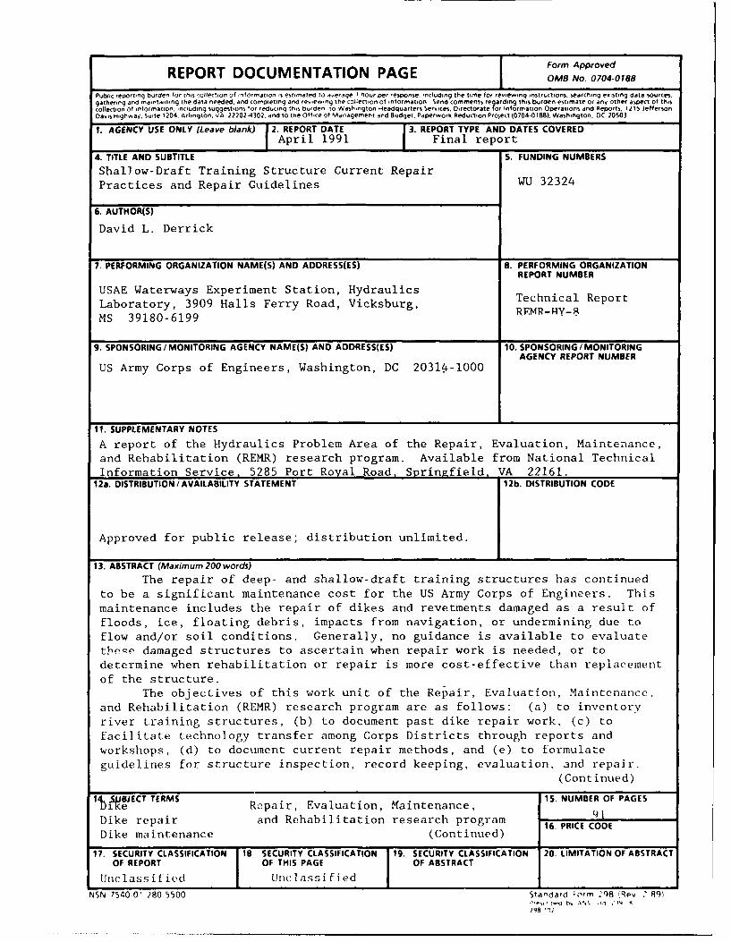
13. ABSTRACT (Maximum 200 words)
The repair of deep- and shallow-draft training structures has continuedto be a significant maintenance cost for the US Army Corps of Engineers. This
maintenance includes the repair of dikes and revetments damaged as a result offloods, ice, floating debris, impacts from navigation, or undermining due toflow and/or soil conditions. Generally, no guidance is available to evaluatetleQp damaged structures to ascertain when repair work is needed, or todetermine when rehabilitation or repair is more cost-effective than replacementof the structure.
The objectives of this work unit of the Repair, Evaluation, Maintenance,and Rehabilitation (REMR) research program are as follows: (a) to inventoryriver training structures, (b) to document past dike repair work, (c) tofacilitate technology transfer among Corps Districts through reports andworkshops, (d) to document current repair methods, and (e) to formulateguidelines for structure inspection, record keeping, evaluation, and repair.
(Continued)
ItSBETTERMS 15. NUMBER OF PAGES140 iSfJECT Repair, Evaluation, Maintenance, 91Dike repair and Rehabilitation research program 16. PRICE CODE
Dike maintenance (Continued)
17. SECURITY CLASSIFICATION 18 SECURITY CLASSIFICATION 19. SECURITY CLASSIFICATION 20, LIMITATION OF ABSTRACTOF REPORT OF THIS PAGE OF ABSTRACT
Unc lass i fied Uriclassified I I
NSN 7540-01 280-5500 Standard Form 98 Rev . 8q)
248

13. ABSTRACT (Continued)
In support of these objectives, this report documents past dike repair work andcurrent repair methods, and includes a set of guidelines for training structureinspection, record keeping, evaluation, and repair. This report also containsinformation on new technology applicable to the field on dike repair.
14. SUBJECT TERMS (Continued)
River training structureRiver training structure repair
PREFACE
The work described in this report was authorized by Headquarters,
US Army Corps of Engineers (HQUSACE), as part of the Hydraulics Problem Area
of the Repair, Evaluation, Maintenance, and Rehabilitation (REMR) Research
Program. The work was performed under Work Unit 32324, "Repair Techniques at
Navigation Training Structures," for which Mr. David L. Derrick, Hydraulics
Laboratory, US Army Engineer Waterways Experiment Station (WES) was Principal
Investigator. Mr. Glen Drummond (CECW-EH) was the REMR Technical Monitor for
this work.
The REMR Directorate of Research and Development Coordinator in HQUSACE
was Mr. Jesse A. Pfeiffer, Jr. (CERD-C), and members of the REMR Overview
Committee were Mr. James E. Crews (CECW-0), Chairman, and Dr. Tony C. Liu
(CECW-EG). The REMR Program Manager was Mr. William F. McCleese (CEWES-SC-A),
and the Problem Area Leader was Mr. Glenn A. Pickering, Chief, Hydraulic
Structures Division, Hydraulics Laboratory.
Data for this final report on shallow-draft training structure past and
current repair practices and repair guidelines were compiled during the period
September 1986-July 1990 by the Estuaries and Waterways Divisions, Hydraulics
Laboratory.
This report was prepared by Mr. David L. Derrick under the general
supervision of Messrs. F. A. Herrmann, Jr., Chief of the Hydraulics Labora-
tory; R. A. Sager, Assistant Chief, Hydraulics Laboratory; W. H.
McAnally, Jr., Chief of the Estuaries Division; M. B. Boyd, Cnief of the
Waterways Division; W. D. Martin, Chief of the Estuarine Eivgineering Branch,
Estuaries Division; C. R. Nickles, Acting Chief of the Totamology Branch,
Waterways Division; T. J. Pokrefke, Chief of the River Engineering Branch,
Waterways Division; and R. F. Athow, Estuarine Engineeritkg Branch, Principal
Investigator. This report was edited by Mrs. M. C. Gay, Information
Technology Laboratory, WES.
Commander and Director of WES during the preparation and publication of
this report was COL Larry B. Fulton, EN. Technical Director was Dr. Robert W.
Whalin.
CONTENTS
Page
PREFACE.................................................................... 1
CONVERSION FACTORS, NON-SI TO SI (METRIC)UNITS OF MEASUREMENT..................................................... 3
PART I: INTRODUCTION.................................................... 4
Background........................................................... 4Objectives........................................................... 4Approach............................................................. 5Philosophy of Purpose................................................ 5Organization of Report............................................... 6Conclusions.......................................................... 6
PART II: COMPILATION OF PAST AND PRESENT DIKE REPAIR PRACTICES .... 8
Kansas City District................................................. 8Little Rock District................................................ 17Memphis District.................................................... 23Mobile District..................................................... 28Alabama River....................................................... 29Apalachicola River.................................................. 33Omaha District...................................................... 36Portland District................................................... 44Rock Island District................................................ 45Savannah District................................................... 50St. Louis District.................................................. 52St. Paul District................................................... 60Tulsa District...................................................... 64Vicksburg District.................................................. 69
PART III: REPAIR LEVEL GUIDELINES AND RECOMMENDEDREPAIR PLANNING PROCEDURES..................................... 75
Introduction........................................................ 75Inspections.................. ........................ 75Repair Criteria..................................................... 79Dike Repair Construction Techniques................................. 82Record Keeping...................................................... 83New Technology....................................................... 85Technology Transfer................................................. 86Funding............................................................. 87
REFERENCES................................................................. 88
BIBLIOGRAPHY.............................................................. 89
THANKS AND APPRECIATION................................................... 89
2
CONVERSION FACTORS, NON-SI TO SI (METRIC)
UNITS OF MEASUREMENT
Non-SI units of measurement used in this report can be converted to SI
(metric) units as follows:
Multiply By To Obtain
cubic feet 0.02831685 cubic metres
cubic yards 0.7645549 cubic metres
degrees (angle) 0.01745329 radians
feet 0.3048 metres
horsepower (550 foot-
pounds (force) per second) 745.6999 watts
inches 25.4 millimetres
miles (US statute) 1.609347 kilometres
pounds (mass) 0.4535924 kilograms
tons (2,000 pounds, mass) 907.1847 kilograms
3
SHALLOW-DRAFT TRAINING STRUCTURE CURRENT REPAIR
PRACTICES AND REPAIR GUIDELINES
PART I: INTRODUCTION
Background
1. The US Army Corps of Engineers established the Repair, Evaluation,
Maintenance, and Rehabilitation (REMR) Research Program to develop new and
improved technology for extending the life of America's water resource
projects. The repair of deep- and shallow-draft training structures has con-
tinued to be a significant maintenance cost within the Corps. This mainte-
nance has included the repair of dikes and revetments damaged as a result of
floods, ice, floating debris, weathering, impacts from navigation, or under-
mining due to river flow and/or soil conditions. No guidance is generally
available to evaluate these damaged structures or to determine when repair or
rehabilitation is more cost-effective than replacement.
Objectives
2. The objectives of this work unit are to inventory navigation train-
ing structures, document past dike repair work, facilitate technology transfer
between Corps Districts through reports and workshops, document current repair
methods, report on new technology applicable to the field of dike repair, and
prepare guidelines for structure inspection, repair criteria, record keeping,
evaluation, and repair.
3. These objectives are met in the following ways:
a. This report documents past and present dike repair methods,reports on new technology in the field of dike repair, and for-mulates guidelines to be used for training structure inspection,repair criteria, record keeping, evaluation, and repair.
b. An inventory of Corps-built and -maintained dikes in shallow-draft, nontidal influenced waterways is available in "Inventoryof River Training Structures" (Derrick, Gernand, and Crutchfield1989).
C. Pankow and Trawle (1988) list structures found in estuarine anddeep-draft navigable waterways.
d. Technology transfer is handled by these three reports, the REMRBulletin, and a workshop held at the US Army Engineer Waterways
4
Experiment Station (WES) in February 1987 entitled REMR Workshop
on Repair and Maintenance of Shallow-Draft Training Structures.This workshop was attended by 45 individuals representing 13Corps Districts and Divisions, plus WES personnel. Ten dis-tricts gave presentations detailing their past and present dike
repair activities, along with their current evaluation andrepair methods. Topics of discussion included repair tech-niques, repair criteria, and research needs in the field of dikerepair. Two reports are available on this workshop: a written
record of the minutes (Derrick 1991), and a videotape recording
of all attending Districts' presentations.*
Approach
4. An examination of the existing literature was carried out. All
Districts with an extensive history of dike repair work were contacted through
symposia and surveys. This information was confirmed, supplemented, and
enhanced by visits to District offices and follow-up telephone conversations
with working level engineers within these Districts.
Philosophy of Purpose
5. A concern voiced again and again by many in the field of river engi-
neering is that the knowledge, wisdom, and experience of the "Old Guard" river
engineers who took part in the planning, design, and construction of the major
river projects (some from the very beginning) are rapidly, through retirement
and death, being lost forever. Most of this knowledge is not written down and
is irreplaceable. These concerns led to a broadening of the information pre-
sented in this report in an attempt to capture and record a portion of this
knowledge. In addition to fulfilling the stated objectives of the work unit,
it is hoped that this docuimnt can serve as a broad-based primer, history
lesson, and guide for young engineers starting out in the field of river engi-
neering. To this end, sections on dike design and construction, descriptions
of projects, types of river traffic, etc., have been included in the report.
David L. Derrick. 1988. "Workshop on Repair and Maintenance of Shallow-
Draft Training Structures, 24-25 February 1987" (unpublished video report),
US Army Engineer Waterways Experiment Station, Vicksburg, MS.
5
Organization of Report
6. The 12 Districts within the Corps that build and maintain dikes were
treated as separate entities and are listed in alphabetical order under
Part II, "Compilation of Past and Present Dike Repair Practices." The follow-
ing topics are covered for each District:
a. Description of project.
b. Stage, discharge, sediment, and dredging.
c. Dike design and construction.
d. Inspections.
e. Types of dike damage.
f. Causes of dike damage.
g. Repair criteria.
h. Repairs and repair techniques.
i. Record keeping.
J. Environmental considerations.
k. New technology.
7. Part III of this report, entitled "Repair Level Guidelines and
Recommended Repair Planning Procedures," consists of repair guidelines on the
following subjects:
a. Inspections.
b. Repair criteria.
C. Dike repair construction techniques.
d. Record keeping.
e. New technology.
f. Funding.
8. A bibliography and a short note of thanks and appreciation to all
who contributed time, information, and effort to this project ends the report.
Conclusions
9. Riverine training structures are recognized by US Army Corps of
Engineers personnel as essential components of the inland waterways navigation
system of the United States of America. As a result they are well maintained
and have been upgraded almost continuously. Due to the cost and importance of
these structures, a great deal of research has been performed throughout the
6
years. In the past this research has usually involved physical model studies,
but some effort is now being devoted to the computer/physical model hybrids
and numerical models.
10. For most of the twentieth century, timber pile dikes were the pre-
ferred choice of training structure. While effective, these dikes were sub-
ject to damage, and consequently, maintenance costs were high. In a rela-
tively short timespan during the early 1960's, all Corps Districts changed
from the use of timber piles to stone for dike construction and repair work.
The stone dikes have proven to be more effective, are very durable, have a
long life expectancy, are less susceptible to some types of damage, usually
require less attention than the timber pile dikes, and generally require less
maintenance as they age.
11. At the present, many of the Districts involved with riverine train-
ing structures are entering a period of transition. As many of the river
projects are completed, or near completion, the Districts are switching from
an engineering-, design-, and construction-oriented workload to a redesign,
repair, and operations and maintenance workload.. For the most part, construc-
tion of new dikes will be limited to the correction of localized problems.
12. Taking an overall view of dike repair throughout the Corps of Engi-
neers, the Districts, as a whole, are doing a commendable job of dike rehabil-
itation and repair. Often faced with shortages in manpower and funds, the
Districts are employing new technology, past experience, and keen engineering
judgment to keep their projects viable for the future.
13. In the future, two areas of utmost importance will be the need to
keep abreast of improvements in technology relating to the field of dike
repair and the need to keep extremely complete and detailed records of the
original river projects and ensuing dike repair work so that these records can
serve as a guide for redesign and repair efforts by future generations of
engineers working on the rivers of America.
7
PART II: COMPILATION OF PAST AND PRESENT
DIKE REPAIR PRACTICES
Kansas City District
Description of project
14. The Missouri River, which begins in Montana and empties into the
Mississippi River near St. Louis, Mo, is approximately 1,900 miles* lorg.
Since the river was shortened approximately 75 miles during -l e course of the
navigation project, the river mileage had to be revised in 1932 and again in
1960. All locations and lengths of the Missouri River listed in this report
are referenced to the 1960 mileage figures. Omaha District oversees naviga-
tion on the upper portion of the river from Sioux City, IA, to R1,Ic, NE, a
distance of 234 miles, and Kansas City District oversees navigation on the
reach of river from Rulo, NE, to the mouth, a distance of 498.4 miles.
Improvement work on the river, consisting of the removal of snags, was first
performed by the Corps in 1832. In 1912, authority was granted by Congress to
maintain a 6- by 200-ft navigation channel from Kansas City, MO, Ir the mouth.
In 1927 authority was extended to encompass the reach of river from Sioux City
to Kansas City for a total navigable length of 734 miles. In 1945 authorit-,
was again extended to increase the channel depth to 9 ft and the channel width
to 300 ft. Under the 1945 authorization, 190 million dollars was spent on the
project. It was completed in 1.980. With the help of over 3,500 dikes, the
channel is entirely self-scouring. While no locks or dams are located within
the Kansas City District, six large dams are located above Omaha, NE, in the
Omaha District. Thus the river flow is controlled from gavins Point Dam (th(,
last dam in the series) downstream to the confluence with the Platte River,
and semi-controlled below that point. With the dams operational, the annual
June flood (caused by snow melt) was completely eliminated and the frequency
and stages of other flood events were reduced. Flow levels can be augmented
with stored water from the reservoirs when natural flows below Gavins Point
Dam are too low. Theoretically the reservoirs have the capacity to supplement
navigation flows through 3 years of drought. The navigation season, basically
when the river is free of ice, usually runs from 1 April to 1 December.
A table of factors for cotnvertifng non-SI units of easurClent to Si
(metric) units is found on page 3.
8
15. In 1985 6.5 million tons of commodities were transported on the
river, with upbound and downbound shipments running about even. Commercial
sands and gravels accounted for approximately 4 million tons of this total.
Other principal upbound products were petroleum, building materials, chemi-
cals, salt, molasses, fertilizers, and steel. Downbound commodities included
grain, grain products, tallow, chemicals, and petroleum products.
16. The standard tow size is four to six barges on the river above
Kansas City. Six to nine loaded barges, or as many as twelve empty barges,
can make up a tow downstream of Kansas City. This number of barges would be
cut in half for the low-water years 1988 through 1990.
17. A typical square-ended barge (also called a box barge) is 200 ft
long, 35 ft wide, and 12 ft high. A barge with an angled end (a rake barge)
is 195 ft long, 35 ft wide, and 12 ft high. Since the sloping end provides
less drag, a rake barge is used as either a lead or trail unit in a tow. A
single barge carries approximately 1,500 tons when loaded to the standard 9-ft
draft. During periods of high water, barges can be loaded to a draft of 10 or
11 ft.
Stage, discharge, sediment, and dredging
18. The normal winter (nonnavigation) average stage on the Kansas City
gage is 10 ft (referenced to a gage zero of +716.4 ft National Geodetic Verti-
cal Datum (NGVD)) with an associated flow of 20,000-25,000 cubic feet per
second (cfs). The normal summer (navigation) target stage, also called the
"full service flow," is 13.9 ft on the Kansas City gage with a flow of
41,000 cfs. Because severe drought gripped this area from 1987 to 1990, flows
had to be reduced to below normal levels during 1988, 1989, and 1990. The
winter flow was dropped to less than 9 ft and 21,000 cfs at Kansas City, and
the navigation flow was reduced to a 12-ft stage with a 38,000-cfs discharge.
This low navigation flow is the "minimum service flow." Due to depletion
because of the drought, it is estimated that 6 years of normal rain and runoff
will be required to fill the reservoirs up to standard operating levels.
19. The sand-silt-clay sediment load before construction of the six dams
on the upper Missouri River was approximately 200 million tons per year.
After the dams were built, the sediment load decreased to 50 million tons per
year, with the percentage of silts and clays decreasing and the percentage of
sand increasing. No dredging was performed from the time the project was
completed (1980) until 1988. Due to the drought and associated low stages,
9
some dredging was performed during 1988 and 1989 (approximately $775,000 each
year) and dredging will be required in 1990. This work was carried out using
a cutterhead type dredge (the Thompson) borrowed from the St. Paul District.
Dike design and construction
20. Early dikes on the Missouri River were constructed of timber piles
in either a single row, double row, or triple row configuration, and were
usually constructed on a willow or lumber mattress. The purpose of the mat-
tress was to reduce scour at the base of the pilings. To aid navigation, a
tall pile clump served as a marker at the river end of the dike. A pile clump
consisted of three timber piles driven close together and angled slightly
(called the batter angle) so that the tops of the piles touched. The piles
were then bound together near their crowns with. wire rope.
21. These dikes were very effective in accumulating sediment. As the
dikes became buried in sediment (actually becoming part of the bank and then
the overbank area), they would be extended into the river, further constrict-
ing the channel. However, due to increases in labor costs and the amount of
damage inflicted by ice, flood, and other forces, the pile dikes were
reinforced with stone.
22. Since the early 1960's, all dike construction and repair work has
employed maximum-weight, 2,000-lb, quarry-run stone. Specifications state
that fines smaller than 1/2 in. cannot exceed 5 percent. This stone is
obtained at any of a number of quarries located adjacent to the river.
23. The "floating plant" method of construction is used almost exclu-
sively. The procedure for this method is as follows: Corps surveyors provide
a baseline from which the contractor can establish the work location. A drag-
line barge is then anchored in position with spuds. Rock is brought to the
work site on flat-decked barges and placed using a dragline bucket controlled
by the barge-mounted crane. At times a "spacer" box is placed between the
material barge and the dragline barge so that rock can be dragged off the
material barge and placed accurately. In situations where the dike is above
water or in shallow water, stone is placed using a clamshell bucket.
24. The only structures not built by the floating plant construction
method were revetments built parallel to the bank during the winter (when the
river was iced over) and some secondary channel closure structures (where the
water was too shallow for the construction barges). For this work, rock was
hauled overland in trucks and dumped.
10
25. The purpose of the dikes was to constrict the width of the river and
stabilize the navigation channel. This practice has been going on for a long
time, and as a result, many of the dikes now extend hundreds of feet into the
present-day banks. Most modern dikes are level-crested and extend 300 to
600 ft into the river. The contraction width, in this District called the
"rectified channel width," varies from approximately 800 ft at Rulo, NE, to
1,100 ft at the mouth of the Missouri River (550 to 750 ft, respectively, in
areas with sills). The contraction width is the distance from the river end
of the dike to the opposite bank, or the river end of a dike to the river end
of a dike directly across from it. The dikes are built with a specified crown
width of 4 ft. The current Construction Reference Plane (CRP), which was
developed in the mid-1970's, revised in 1982, and revised again in 1990, is
designed to give a design consistency regarding river training structure
heights. Building dikes referenced to the CRP would theoretically have all
structures overtopped for the same number of days each year. The CRP is based
on the flow that is equal to or exceeded 75 percent of the time (during the
navigation season) and takes tributary flow into account as one moves down the
river. River training structure design heights range from -2.0 to +6.0 ft
CRP, depending on location and type of structure, with heights increasing as
the mouth of the river is approached. Dikes are normally spaced 600 to
1,000 ft apart in the reach from Rulo, NE, to Kansas City, MO, and 800 to
1,000 ft apart from Kansas City to the mouth. Generally speaking, dikes are
farther apart on convex bends and closer together in straight reaches. The
spacing seems to be a function of the radius of the bend since flatter bends
do not exert as much control over the flow and closer spacing is required.
When additional dikes were required after the initial construction of a sys-
tem, these spacing guidelines were not strictly followed. Most dikes are not
marked; but in two or three cases where the dikes are a clear hazard to navi-
gation, a pile of rock 20 ft long and 3 to 4 ft tall is used to mark the river
end of the dike. This marker aids a pilot in determining the location of the
dike during periods of high water when the dike is submerged. In some areas,
low-elevation sills, or sill extensions on existing dikes, are employed. A
sill, by this District's definition, is a dike that is submerged more than
95 percent of the time.
26. Many different types of river control structures are used, including
L-head dikes, chute closure dikes, bankheads, convex dikes (located on the
11
inside bank of a bendway), concave dikes (located on the outside bank of a
bendway), kicker control structures, crossing control structures (used to tie
a kicker control structure to the bank), floodwalls, and low-elevation
underwater sills.
Inspections
27. The District schedules spring, summer, fall, and almost always,
winter inspections. These examinations are staffed by inspectors from the
Engineering and Operations Divisions of the District, along with personnel
from the Missouri River Division office and the District project office at
Napoleon, MO. It is felt that a careful inspection of all river training
structures four times a year is sufficient.
Types of dike damage
28. The following types of dike damage are reported by the District:
a. Settling of stone (usually in the first 2 years after a dike isbuilt).
b. Flanking.
C. Loss of rock at the channel end of the dike.
Causes of dike damage
29. The following causes of dike damage are reported by the District:
a. Ice and ice bridging.
b. Floods.
c. Propwash.
d. Natural weathering of rock.
e. General wear and tear.
f. Towboat impacts (infrequent).
Repair criteria
30. The following criteria are used to determine when, or if, a dike is
in need of repair, or redesign and reconstruction:
a. Integrity of the project.
b. Adequacy of navigation channel.
c. Presence of serious bank erosion.
d. Integrity of individual structures.
t. Integrity of structure system.
f. Environmental consequences.
Z. Extent of damage.
h. Location of the structure.
12
i. Type of structure.
j.. Available funding.
31. In some cases these criteria would be weighed equally; in other
cases some items would carry more weight than others.
32. Specific criteria for required structure repair are as follows:
a. Serious bank erosion.
b. Inadequate navigation channel.
c. Structure degraded more than 2 ft.
d. Damaged area more than 100 ft long.
Repairs and repair techniques
33. Most repair work is now performed by private contractors. One per-
cent or less is accomplished by Corps of Engineers crews and equipment. The
contractors who work the river have years of experience and are familiar with
Corps guidelines and methods. During a normal year, 200,000 to 250,000 tons
of quarry-run, maximum-weight, 2,000-lb stone is used for dike repair. Speci-
fications for this stone are the same as the stone used for dike construction.
Stone cost "in place" is approximately $8 to $10 per ton (1990 costs). Typi-
cally 75 to 100 dikes are repaired each year. The floating plant method of
construction is used for all repair work. Usually two repair contracts are
let each year, one covering the reach from Rulo, NE, (mile 498.4) to Miami, MO
(mile 262.4), and the other from Miami to the mouth of the river (mile 0.0).
The length of a repair contract varies with the amount of rock required, but
generally runs for 3 to 6 months. The repair contracts can be modified to add
or delete dikes if a low-water inspection reveals more information. If more
or less stone is needed than originally specified, the contract can be modi-
fied up to plus or minus 15 percent of the total dollar amount of the contric-
without having to renegotiate the contract bid price.
34. Kansas City District personnel have detected an apparent pattern for
repair work regarding newly constructed dikes. During the first 2 years aftcr
a dike is built, it usually settles slightly, and a small amount of stone has
to be added to the dike to bring it up to grade. Then it is typically 10 to
20 years (under normal conditions and without major ice damage) before the
dike requires further repairs. Abnormal conditions may, of course, necessi-
tate repairs at any time.
Record keeping
35. The construction and repair history of all dikes and revetments are
13

recorded and maintained in the "Structure History File of the Missouri River."
Prior to 1979 this information was handwritten on file cards. In 1980 this
file was computerized. All structure histories were entered into and are
presently stored in the Kansas City District's computer.
36. The following information on each structure is included in this
file:
a. Type of structure: dike, revetment, or pilot canal.
b. Structure number.
C. Location by:
(i) River mile.
(2) Region/basin.
(3) Congressional District.
(4) County.
(5) State.
(6) Beginning and ending stations.
(7) Bank of river, either left or right.
d. Cost of original structure.
e. Cost of any repair work done to structure.
f. Material used in construction or repair: timber pile, stone,
or both.
g. Whether or not the river end of the dike is marked to aid in
navigation.
h. Elevations of the following:
(1) Marker piles.
(2) Pilings.
(3) Stone.
All elevations are referenced to the National Geodetic Vertical
Datum of 1929, i.e., mean sea level.
i. Work contract number.
j-. Type of labor used: contract or hired labor.
k. Description of work performed.
1. Date dike or revetment was originally built.
m. Dates of any subsequent repairs.
n. How work was funded: either with new construction funds or
maintenance funds.
o. Whether or not the dike has an enivironmental notch.
p. Notch type, either built in or excavated.
14
37. The computer program allows the user to extract certain data from
the file within specific limits or geographical areas. For example, total
number, cost, and length of all structures, or specific type of structure
(dike, revetment, pilot canal) can be retrieved for a certain reach, bank of
river, region, county, metropolitan area, Congressional District, or contract
number (or hired labor) for the total period, a specific year, or other time
period. It is also possible to separate construction performed with Construc-
tion General Funds from construction charged to Operations and Maintenance.
The number of the various types of environmental notches can also be retrieved
within the specific limits outlined in the previous paragraph. This program
has proven to be a useful and powerful tool in river engineering work.
Environmental considerations
38. The project impact upon the natural environment has been a concern
of the Kansas City District for many years. District personnel have worked
with state conservationists and fish and wildlife personnel to develop many
plans to improve the near-field aquatic environment of dikes and revetments.
Toward this end the following actions have been undertaken:
a. Some previously closed chutes (secondary channels) have beenreopened.
b. Water supplies to oxbow lakes are being maintained.
c. Dredged material disposal areas have been moved to 100 ft fromthe bank, thereby creating submerged bars or islandq.
d. Dikes are not being built as high or as long as in the past.
e. Vane dikes and sills disconnected from the bank are being con-structed for the purpose of preventing additional losses ofaquatic area and to develop small secondary channels.
f. Environmental notches in dikes (see paragraph 40).
g. Rough dike surfaces (see paragraph 43).
h. Selective minimum maintenance (see paragraph 44).
i. Underwater sills (see paragraph 45).
39. These actions are taken only when the project purposes of navigation
and bank stabilization are not adversely affected.
40. Notches in dikes. The Kansas City District has notched approxi-
mately 1,700 dike and revetment structures over the last several years.
Usually a notch 50 ft wide is cut into the dike, or in the case of a dike that
has suffered some degradation, this area is simply not built back to grade.
The bottom elevation of the notch is usually 2 ft below the CRP. The notch
15
allows flow through the dike, which keeps the area downstream of the dike from
accreting. This practice serves three purposes:
a. To keep the bank from infringing on the flood-carrying capacityof the river.
b. To increase the water-surface area for fish and other aquaticinhabitants.
c. To form steep clay banks. These banks are prime habitat forcaddis flies and mayflies, which are an important link in thefood chain of fish.
41. Dike performance has not been affected by the notches, and there has
been no noticeable increase in maintenance costs. The notches are designed to
work at low and midbank flows. Most dikes on the Missouri extend from 300 to
600 ft into the river, with the notch located 50 to 100 ft from the bank.
Even if the notch causes some bank erosion, dike failure is unlikely as most
of the dikes extend hundreds of feet back into the bank (see paragraph 21).
If the notch is in the L-head portion of the dike, it is usually located
within 50 ft of the break in the dike. Of the 1,700 dikes notched, only about
a dozen notches have had to have been filled back in, usually because of bank
erosion.
42. The environmental effects of the notch program were studied at WES
and are discussed in Pennington et al. (1988).
43. Rough dike surface. Representatives of the Missouri Department of
Conservation prefer irregular and rough surfaces on dikes and revetments on
the Missouri River. Termed "diversity of habitat," these rough surfaces allow
a greater surface area for zooplankton and other important fish food chain
organisms to live and grow. In the Kansas City District, the contractor uses
the dragline bucket to smooth the dike after construction. However, the
quarry-run stone used contains significant fines; after a period of high water
the fines wash out, leaving the surface irregular. To highlight one differ-
ence in river engineering, environmentalists in the Portland District require
a smooth surface on dikes and revetments on the Columbia River (see
paragraph 165).
44. Selective minimum maintenance. After the biological and natural
habitat responses were considered, some dike design heights and widths have
been reevaluated. In dike fields on satisfactory radius bends with no naviga-
tion problems where the system has performed its function, or in areas where
the dikes are felt to be too long, ever), other dike has been allowed to
16
degrade. In some cases the riverward ends of dikes have been allowed to
deteriorate. In areas where no major damage is likely, alternate segments of
revetments have been allowed to deteriorate to a limited degree.
45. Underwater sills. Since the mid-1970's, in areas where there is a
need to further constrict the river, underwater sill extensions on existing
dikes have been successfully employed. This technique has satisfied the envi-
ronmentalists, who, in most cases, are opposed to the building of emergent
structures. As stated earlier, the definition of a sill in the Kansas City
District is a structure that is submerged at least 95 percent of the time.
Contacts
46. Kansas City District engineers contacted to provide information were
Messrs. Thomas Burke and Charles Wyatt. Additional information was provided
by Mr. Warren Mellema of the Missouri River Division.
Little Rock District
Description of project
47. Responsibility for navigation in the Little Rock District starts at
the confluence of the White and Mississippi Rivers (mile 599), goes up the
White River to the Arkansas Post Canal (mile 9.6), follows that to the
Arkansas River (mile 19.0), and travels up the Arkansas River to the District
boundary at Fort Smith, AR (mile 308.6). Tulsa District has jurisdiction over
the Arkansas River upstream of Fort Smith. This project was authorized in
July 1946 and construction began in 1957. The project was opened to naviga-
tion in 1970 and essentially completed by 1974. Some portions of the river
are still being "fine tuned" (for example, numerical modeling of the reach
immediately downstream of Lock and Dam 3). Channel dimensions are 9 by 300 ft
for both the White River and the Arkansas Post Canal, and 9 by 250 ft for the
Arkansas River. The Little Rock District presently maintains 1,018 dikes and
12 locks and dams (all locks sized 110 by 600 ft) on its reach of the Arkansas
River.
48. The standard tow size on the Arkansas River is eight barges in a
three-wide by three-long configuration with the towboat occupying the middle
slot of the last row of barges. The maximum tow size is 17 barges in a 3 by 6
configuration with the towboat again occupying the middle slot in the last row
of barges. Overall tow length is limited to 1,200 ft due to the tight radii
of some bends.
17
49. Approximately 8.3 million tons of goods were shipped within and
through the District in 1989. Commodities shipped and their percentage of
total tonnage during that year included sand and gravel (24.3 percent), chemi-
cal fertilizers (17.1 percent), wheat (13.4 percent), other gr-ins (4.8 per-
cent), petroleum products (12.4 percent), iron and steel (9.3 percent),
soybeans (6.6 percent), chemicals (2.9 percent), coal (1.3 percent), rock
(0.3 percent), and miscellaneous goods (7.3 percent).
Stage, discharge, sediment, and dredging
50. Approximately 30 reservoirs located in the upper reaches of the
river system (within the Tulsa District) help control the flow of the river.
The maximum discharges for the Arkansas River (measured at the Little Rock,
AR, gage) follow: for preproject conditions, 700,000 cfs, stage of 33.0 ft
CRP, in April of 1927; and for postproject conditions, 406,000 cfs, stage of
42.1 ft CRP, recorded on 1 May 1990.
51. Suspended sediment load on the Arkansas River (measured at Little
Rock) for the period 1965 to 1978 averaged 11,521,000 tons per year. Within
that period the suspended sediment load varied from 1,723,000 tons (1977) to
28,555,000 tons (1973). When water supplies allow, water stored in the
upstream and tributary reservoirs may be released to increase velocities in
the river and scour sediment deposits from the navigation channel.
52. Each year the Little Rock District awards two maintenance dredging
contracts. The contracts run concurrently, are of 1-year duration, and start
in January. Both contracts cover miles 0.0 to 444.8 on the Arkansas River,
the lower 20 miles of the White River, and the harbors at Rosedale, MS, and
Greenville, MS. Two cutterhead type dredges are used, with one dredge
assigned to the Russellville Area Office and the other to the Pine Bluff Area
Office. However, both dredges are free to work in any area covered by the
contracts. From 1979 to 1989, dredging varied from 329,000 (1980) to
5,953,000 (1988) cu yd per year, with an average of 1,944,090 cu yd of mate-
rial dredged per year over the entire period. Total costs per cubic yard
varied from $1.11 to $2.42, with an average of $1.28 over this 11-year span.
These dredging cost figures include dredging, standby time, mobilization,
demobilization, and transportation costs. This amount does not reflect the
expense associated with raising the levees around the dredge disposal areas
(which is performed under a separate construction contract). Typically the
levees must be raised once every 5 to 7 years.
18
Dike design and construction
53. In 1946 the McClellan-Kerr Arkansas River Navigation System (encom-
passing the Verdigris and Arkansas Rivers, the lower 10 miles of the White
River, the Arkansas Post Canal, and San Bois Creek) was authorized. The first
dikes were built in the late 1950's. Their purpose was to keep the river from
meandering. Upstream of Little Rock, AR, stone dikes were used (because of
bedrock in the riverbed); and downstream of Little Rock, timber pile dikes
(with limited stone fill) were employed. The pile dikes consisted of two rows
of clumps spaced 7.5 ft apart with each clump containing three pilings bound
together with wire rope. Untreated pilings were used for dikes where sediment
was expected to accrete rapidly, and treated pilings were used for the river-
ward 100 ft of all dikes in areas where sediment was not anticipated to
accumulate rapidly.
54. Pile revetments were constructed using either two rows of clumps
(three pilings to a clump) spaced 7.5 ft apart,'or with two rows of single
piles spaced 5 ft apart.
55. All structures built after the navigation pools were raised in the
late 1960's were of stone-fill construction. These dikes and revetments were
designed to stabilize the banks and constrict the river, thereby helping to
maintain navigable depths by clearing sediment from the channel. The con-
tracted width of the river varies from 700 to 1,400 ft, depending on location.
Maximum-weight, l,000-lb, quarry-run stone (50 percent must weigh more than
40 lb, not more than 8 percent finer than 1/2 in.) is used for construction of
all dikes having a thickness greater than 5 ft. Maximum-weight, 350-lb,
quarry-run stone (50 percent must weigh more than 25 lb, not more than 8 per-
cent finer than 1/2 in.) is used for bankheads, trench-fill revetments, and
dike sections that are less than 5 ft thick. This stone is extracted from a
number of quarries along the river, and from quarries located in Kentucky and
Illinois. Stone samples are sent to the Geotechnical Laboratory at WES to
determine suitability.
56. A few dikes are angled normal to flow, but most are angled 15 to
30 deg downstream from normal. Also, all dikes are built normal to the bank
for at least their first 200 ft. Due to these design specifications, in many
cases the dike is not straight, but "broken." L-head dikes are also used.
57. Stone dikes built by floating plant have a specified crown width of
0 to 5 ft. Dikes built by end dumping have a design crown width of 10 ft, but
19
as built, the crown is typically 12 ft or wider. Where bankheads were used,
the bank was paved 25 ft upstream and 75 ft downstream from the center line of
the dike. Most dikes start at a +12- or +13-ft elevation (referenced to the
CRP) at the bank end and slope to a +10-ft elevation at the river end. How-
ever, some dikes and L-heads were built to elevations as high as +24 ft and as
low as zero CRP. Side and end slopes were I.OOV on 1.25H.
58. Dike spacing varies. In areas where the preproject river channel
was wide and had to be contracted with long dikes, the dikes were spaced far
apart. In areas where the existing channel was almost narrow enough and had
to be contracted only a few hundred feet, the dikes were spaced much closer
together. Dikes placed on the convex side of a bend were generally spaced
farther apart than those placed on the concave side of a bend. The intent of
the varied spacing was to minimize the lengths of the structures required and
yet provide the contraction needed to maintain navigable depths. Currents
were assumed to enter the dike field from the riverward end of a dike at an
angle of 15 deg to the current in the main channel. The next dike downstream
was placed to intercept this entering current at a point 200 ft from the
riverward end of the dike. In areas where dike lengths were less than 200 ft,
the dikes were spaced to intercept the entering current before it hit the bank
line. Dikes considered to be a hazard to commercial navigation were marked
with a 16-ft, lO-in.-diam treated timber pile. Eight feet of the pile is
below the crest of the dike encased in a 12-in.-diam steel pipe. Other dikes
were marked with steel H-piles driven into the crown of the dike.
Inspections
59. Design office personnel inspect the entire river by boat once a
year, usually in the fall (late September-early October). This inspection
takes a week and is a continuation of the Tulsa District's inspection trip.
Some Little Pock District personnel participate- in the Tulsa District inspec-
tion trip (and vice versa) to get a better feel for overall conditions on the
entire river. Each river training structure visible from the navigation
channel is examined, damaged dikes are noted on the navigation charts, mainte-
nance recommendations made, and needs prioritized. The only dikes not
inspected are those structures submerged in the pool areas. Additional
special inspections are made after floods or other unusual situations. Resi-
dent office personnel (while performing weekly channel surveys) and landowners
occasionally spot and report damaged dikes and damaged bank lines. Aerial
20
photographs are used mainly to detect dike flanking and bank scalloping and to
track the growth rate of bank scallops. A scallop is bank erosion in a semi-
circular pattern occurring downstream of a dike.
Types of dike damage
60. This District experiences very few total dike failures. The major-
ity of the dike damage would fall into the category of loss of dike height,
although flanking of dikes at the bank end, bank scallops, excessive scour
downstream of a dike, and scour at the toe of revetments have all caused
problems.
Causes of dike damage
61. The District reports the following causes of dike damage:
a. Extreme floods.
b. Wind-driven wave action.
c. Towboat propwash.
d. Errant tows running through dikes.
e. Sandy, unstable soil (bank scallops, flanking, excessive scour,etc.)
f. Dikes being "notched" by fishermen.
Repair criteria
62. A low area of a structure is usually not repaired unless the naviga-
tion channel has become too narrow or too shallow, or if the degraded section
of the dike has the potential of becoming much larger. Dredging records of
the immediate area are reviewed at this point. Generally, if the crown eleva-
tion has degraded 1 or 2 ft without adverse navigation problems, action is not
taken. If the crown has degraded 4 or 5 ft over a length of 25 or 50 ft or
more, then stone is added to the structure to bring it up to original grade.
In areas where increased navigation depths are required existing dikes can
either be lengthened or raised, but in most cases the dikes are raised.
63. The District tries to ensure that all structures remain attached to
the bank. Bank scallops forming downstream of a dike have been a problem in
the past. These scallops can enlarge, causing the dike to be flanked. If it
appears the dike will be flanked, the bankhead is extended with stone,
revetting the bank from the dike root downstream to a point at least past the
midpoint of the scallop, or for 150 ft, whichever is less.
Repairs and repair techniques
64. Typically 30 to 50 dikes are repaired in a normal year. All dike
21
repairs are performed using maximum-weight, 1,000-1b, quarry-run stone.
Revetment repairs ure maximum-weight, 350-Ib, quarry-run stone. Cost "ini
place" for the 1,000-lb stone is approxinately $10 to $14 per con. Dike
repair work usually runs from $600,000 to $700,000 per year. In recent years,
budget restraints have caused the District to delay some needed repairs in
order to use those funds to correct major problem reaches. Almost all rvpair
work is handled by private contractors; less than 1 percent is performed by
the Corps.
65. After the fall inspection, repair contract specifications are worked
up over the winter, contracts are let for bids in the spring, and the actual
repair work is performed during the summer low-water construction season. The
repair work is handled by five or six contracts, with each contract usually
covering a I- to 2-mile reach of the river. if, however, some of the dike
damage is serious and cannot wait until the next construction season, th n
those repairs are carried out quickly. In the event of a major flood ,'ith
widespread damage, i.e., the May 1990 flood, an emergency repair contract (or
contracts) would be let and repair work performed as soon as possible.
66. Both floating plant and end dumping repair tec .niques are employed,
depending on dike location and river stages. The life of repairs is long, but
because of the large number of structures, repair work is performed every
year.
Record keeping
67. For record keeping purposes, the river is divided into pools and a
separate book is kept on all structures within each pool. For example, all
data pertaining to the structures upstream of Lock and Dam 4 but downstream of
Lock and Dam 5 would be found in the volume called "the pool 4 book." The
inside cover of these hooks feature an aerial photograph of the stretch of the
river covered by the book, with all structures clearly marked and identified
by stracture number. The book contains a list of all structures, with the
work performed on each structure listed by contract specification number and
the dates that the contract work was performed. The book also contains the
original design, or as-built drawings, and all subsequent repair contract
drawings. It i5; updated every time a construction or repair contract i; Iet
Environmental cons ;iderations
68. No notches have been excavated from existing dikes and essentially
no new dikes are being built. lowever, in about 20 dikes where repairs were
22
required due to degradation of dike height, an area has been left to act as an
environmental notch. This program was initiated in 1983. The width of the
degraded area is usually 10 ft, with the bottom elevation 5 ft below normal
navigation pool. Most notches are in stone-fill revetments or are close to
the river end of the dike. The notches increase the flow of water through the
dike, thereby creating a larger backwater area with improved water quality for
wildlife and fish habitat. Recreational fishermen can also use the notches to
gain access to fishing areas without having to go around the end of the dike
and into the main channel of the river. See paragraph 40 for more detailed
information.
Contacts
69. Little Rock District engineers contacted to provide information were
Ms. Leanne Minery and Messrs. Jim Baker, Dou Bratton, and Robert Young.
Memphis District
Description of project
70. The Mississippi River, which begins in the state of Minnesota and
empties into the Gulf of Mexico through major distributaries at Head of
Passes, Louisiana, has a navigable length of 1,811 miles. Six Corps Districts
have jurisdiction over specific sections of the river. Starting at the
upstream head of navigation and moving downstream, the Districts are St. Paul.
Rock Island, St. Louis, Memphis, Vicksburg, and New Orleans.
71. The Memphis District oversees navigation on 354.8 miles of the river
from the confluence of the Ohio and Mississippi Rivers at Cairo, IL
(mile 953.8), to the mouth of the White River (mile 599.0). Vicksburg Dis-
trict also has maintenance responsibilities over the dikes and revetments on
the left descending bank of the river (adjoining the state of Mississippi)
from mile 614.0 to mile 599.0. Work on the river is authorized and funded by
the Flood Control, Mississippi River and Tributaries Act of 1928. There are
no locks or darns located within this reach of river. The authorized naviga-
tion channel is 9 by 300 ft. The river is up to 120 ft deep in places and up
to 2 miles wide, and has a meander belt 30 to 50 miles wide. Currently 273
dikes are maintained, with 105 dikes scheduled to bc built by the year 2010 to
complete the Master Plan for the river within this District.. Three to fiv,
(likes are scheduled to be built each year until the Master Pln is complet,.
23
72. The typical size of a tow is 25 to 30 barges in a 5-wide by 5-long,
or 5-wide by 6-long barge configuration, but under ideal river conditions up
to 35 barges downbound and 45 barges upbound can be moved. Tow size would
depend on river stages and the mix of loaded and empty barges within the tow.
Towboat power is in the 5,600- to 10,000-horsepower range.
73. Approximately 169 million tons of commodities were shipped on the
reach of river from Cairo, IL, to Baton Rouge, LA, during calendar year 1988.
This section of river includes all of the Memphis and Vicksburg Districts and
a portion of the New Orleans District. Major commodities shipped during 1988,
and their percentages of the total tonnage, included coal (18.3 percent), corn
(17.8 percent), soybeans (8.5 percent), animal feed (5.3 percent), basic chem-
icals (4.4 percent), articulated concrete mattress (3.8 percent), wheat
(3.8 percent), gasoline (3.7 percent), and miscellaneous (34.4 percent). The
busiest port within this District was the city of Memphis, TN, with 10.2 mil-
lion tons of goods handled in 1988.
Stage, discharge, sediment, and dredging
74. All stages and discharges listed were recorded at the Memphis gaging
station in feet above an arbitrary gage zero. Maximum stage and discharge
were 48.7 ft and 2,020,000 cfs, respectively, on 10 February 1937. Minimum
discharge was 78,000 cfs on 25 August 1936. Minimum stage was -10.7 ft on
10-11 July 1988. The bank-full stage and discharge are 34.0 ft and
1,312,000 cfs, respectively.
75. Suspended sediment data are not collected by the Memphis District.
The United States Geological Survey based in Little Rock, AR, has a gaging
station at Memphis, but data are only collected six times per year. Using
this source of information, for the period February 1973 to May 1990 (116 sam-
pies), the suspended sediment load averaged 268,632 tons per day. This figure
is probably low, as many higher flows (which would carry the most sediment)
are missed. Suspended sediment consists mainly of silts and sands.
76. An average of 28,165,267 cu yd of material per year was dredged
during the period 1985-1989. Total cost per cubic yard varied from $0.29 to
$0.53, with an average cost of $0.36 for the entire period. Dredging is car-
ried out using four dustpan type hydraulic dredges. Three are Corps owned:
the Burgess (Memphis District), the Potter (St. Louis District), and the
Jadwin (Vicksburg District). The fourth, the Lenel Bean, is owned by Bean
Dredging of New Orleans, LA, and is under a year-round rental contract with
24
the Memphis District. The contract length is I year, with a 1-year option.
Since the dredging program is under Lower Mississippi Valley Division (LMVD)
supervision, these four dredges are used wherever the need is greatest within
the Districts comprising LMVD (St. Louis, Memphis, Vicksburg, New Orleans).
Dike design and construction
77. Several different permeable pile dike designs have been employed on
the river, starting in 1881 with dikes constructed of timber piles arranged in
a single row. Designs with up to six rows of pile clumps (with three pilings
making up a clump) were used. Pile dikes were built up until 1966 as river
training structures. In 1964 and 1965 some dikes were built of stone with a
maximum upper weight limit of 2,000 or 3,000 lb. Since 1966, almost all dike
construction and repair has employed Graded Stone A, a 5,000-lb maximum-weight
stone. Many of the old deteriorated pile dikes have been filled to midbank
height with stone.
78. The basic design criteria for stone dikes are;
a. Spacing one to one and a half times the dike length.
b. Alignment normal to flow.
C. Grown width, minimum of 6 ft, maximum of 30 ft.
d. Horizontal crest profiles set at midbank height or 15 ft above
the Low Water Reference Plane (LWRP).
e. A drop of 5 ft in the first 250 ft (bank end) to the designelevation to reduce scour near the bank.
f. A drop of 10 ft in the last 500 ft of the dike (stream end).
g. Side slopes of IV on 1.25H.
h. A stream end slope of IV on 5H (this flatter slope has beenfound to reduce end scour).
79. In addition, the bankhead is graded to a IV on 3H slope and paved
with stone 35 ft upstream and 200 ft downstream of the axis of the dike.
Minimum contraction width varies within the District from 3,000 to 2,500 ft.
This contraction width is measured from the -10-ft (LWRP) to -10-ft contours
on each side of the river. The basic dike types used by the District include
transverse, closure, trail, and lateral. Transverse dikes are the most com-
mon, are usually built in systems (also called fields) of three to four dikes,
and are typically angled normal to flow. The purpose of a transverse dike is
to increase the cross-sectional area of the channel by concentrating flow in
the low-water channel. Closure dikes generally extend from the riverbank to
an island or high bar. This closes off the secondary channel, which in turn
25

directs more water into the main channel. A trail dike is a downstream branch
of a transverse dike. It usually starts about 500 ft from the riverward end
of a transverse dike and can either be angled slightly toward the river, or
extend downstream parallel with flow and then angle normal to flow near its
end. The purpose of the trail dike is to act as an additional transverse dike
without having to be tied to the bank. A lateral dike is built on a smooth
alignment along the bank and is used to straighten out any misaligned currents
caused by bank scallops or pockets. The floating plant method of dike con-
struction is used for most dike building within this District.
Inspections
80. An intensive dike inspection is carried out each year, usually in
July or August, ideally when stages are at +10.0 ft LWRP or lower. A 5.0-ft
stage is even more desirable as a larger portion of the dike would be visible.
This inspection trip takes 2 weeks. Each dike is visually inspected and any
damage is noted.
81. The Navigation Section regularly patrols the river and sometimes
reports dike and revetment failures. Aerial photographs taken each year can
be used to spot and analyze dike damage. Landowners and towboat captains also
frequently observe and report damage.
Types of dike damage
82. The following types of dike damage are reported:
a. Top of dike degraded.
b. Flanking of the dike at the bank end.
c. Holes in the dike, usually leading to concentrated flow throughthe hole with deep scour occurring immediately downstream of thehole in the dike. In some cases the dike repair must be offsetupstream of the original alignment to skirt the scoured area.
d. Scouring of the bank downstream of the dike, usually caused by
turbulence and eddies.
Causes of dike damage
83. Dike damage is caused by the following:
a. River currents (felt to be the major cause of damage).
b. Floods or extended periods of high water.
C. Towboats hitting the dikes.
d. Drift and debris.
e. Ice (usually minor).
26
Repair criteria
84. The question of whether or not to repair a dike is usually left up
to the project engineers. Based on experience, observation, and engineering
judgment, a decision is reached. A dike with major damage, so much so that
the extent of the damage could not be fully observed, would be surveyed to
ascertain what losses had occurred. Low sections in a dike that concentrate
flow through the dike are repaired quickly. If a dike appears to have
degraded uniformly, then the condition of the channel is studied. Thought
would be given as to whether or not the dike is performing its intended pur-
pose. If the dike is still functioning well, it may not be repaired. How-
ever, a drop in performance would necessitate repairs, usually to as-built
specifications.
Repairs and repair techniques
85. Generally $10 to $12 million is spent by the Memphis District on
revetment and dike repairs during a typical year. About $3 million of this is
for stone repairs to dikes and to the upper slope of revetments. The in-place
cost of stone is approximately $10 per ton, with approximately 300,000 tons of
stone used annually. Graded Stone A is used to repair substantially degraded
portions of dikes. Riprap (maximum weight 125-lb stone) is used on dike bank-
heads, thin sections of dike restoration, and revetment repairs. The stone is
transported by barge from quarries along the Upper Mississippi, Tennessee, and
Cumberland Rivers. Thirty dikes are repaired during a typical year. Almost
all repairs are carried out using floating plant equipment.
86. Using statistics and past experience, specifications are drafted and
advertised for bids in May, and the contracts are awarded in June or July.
One parcel covers the reach of river from Cairo to Memphis, and the other from
Memphis to the White River. The contracts are based on a unit price for
stone, earthwork, etc., plus a price for mobilization and demobilization.
87. Information obtained from aerial photographs, surveys, and the in-
spection trip is used to develop detailed plans, specifications, and estimates
for repairs. This work is begun immediately after the inspection trip. Most
repair work is performed from August through December. If more work than
usual is required, the contract length is extended into January.
88. All maintenance and repair money is handled by budgetary request.
Historical records are used to estimate the amount of money needed for the
coming year. Floods or other unforeseen events make an accurate estimate
27

difficult. If funds will not cover all repairs needed during a specific year,
the various repair projects are prioritized.
Record keeping
89. The files contain the original design drawings, record maps showing
as-built conditions, and sometimes after-construction surveys of all dikes in
the Diqtrict. When repair work is performed on a structure, the record maps
are modified to show the work carried out. The file is updated each time work
is performed on a dike.
90. The Channel Improvement Data Report contains financial and other
data on dikes and revetments. Included is the original cost, the condition of
the area before dikes were built, the original purpose of the structure, the
anticipated effect of the dike, dates and costs of repairs, and a brief
description of the work done. Construction and maintenance costs are also
included.
Environmental considerations
91. In 1990 a few new dikes are scheduled to be notched for environ-
mental enhancement in a manner similar to the notched dikes in the Kansas
City, Omaha, and St. Louis Districts. The notches vary in size. See para-
graph 40 for more information on the benefiLb of dike notching.
New technology
92. Laser transits and other modern electronic surveying equipment are
now being used to locate and position the barges when placing stone during
dike construction or repair.
Contacts
93. Memphis District engineers contacted for information were
Messrs. Donald Jackson, Bobby Littlejohn, Andrew Lowery, Jimmy Thompson, and
Doug Young.
Mobile District
94. Since this District maintains dikes on both the Alabama and
Apalachicola Rivers, the dike repair methods of each river system will be
reviewed separately.
28
Alabama River
Description of project
95. The confluence of the Coosa and Tallapoosa Rivers form the Alabama
River just north of Montgomery, AL (river mile 355). The Alabama River joins
the Tennessee-Tombigbee Waterway at mile 45, and then flows into Mobile Bay
near Mobile, AL (mile 0). Three locks and dams are situated on this river,
all with lock dimensions of 84 by 600 ft. The Coosa and Tallapoosa rivers
both have a series of hydropower dams, but the reservoirs do not have much
flood storage capacity, making the Alabama River system semicontrolled. The
Alabama River is navigable over its entire length. The Coosa and Tallapoosa
Rivers are not navigable, although navigation feasibility studies of the Coosa
River have been carried out. The River and Harbors Act of 1927 authorized the
Corps to study these rivers to determine possible future uses. Construction
of the locks and dams was initiated in 1962 and completed during the early
1970's. The District also built 39 dikes in the lower 72 miles of the project
during this time period. Major dike revisions and additions are under con-
struction or planned for the time period 1989-1991. The authorized channel
dimensions are 9 by 200 ft. The project is not complete.
96. Typical size of a tow on the Alabama River is four barges for dry
cargo in a two-barge-wide by two-barge-long configuration, and two barges in a
side-by-side configuration for liquid cargo. The reason for this difference
is that a liquid cargo barge is slightly larger (42 by 220 ft) than a dry
cargo barge (35 by 200 ft).
97. During the period 1979 to 1984, an average of 3,068,000 tons of com-
modities were transported yearly. Major commodities and their percentage of
the total tonnage included construction materials (51.8 percent), paper pro-
ducts (42.4 percent), agricultural products (2.6 percent), petroleum products
(2.2 percent), and chemicals (I percent).
Stage, discharge, sediment, and dredging
98. All stages are in feet above mean sea level, and were recorded at a
gage (mile 76.0) downstream of Claiborne Lock and Dam. Highest and lowest
tailwater elevations recorded were 56.6 ft (25 March 1990) and 6.0 ft
(8 October 1986), respectively. Highest and lowest discharges of record were
267,000 cfs (March 1961) and 2,850 cfs (1970), respectively. Bank-full stage
and discharge are 21.0 ft and 30,000 cfs, respectively.
29
99. The sediment load of this river is estimated at 1.5 million tons per
year. Most sediment consists of silty sand with some gravel. An average of
1,047,000 cu yd of material per year was dredged for the period 1971-1986.
The cost per cubic yard varied from $0.34 to $7.47, depending on the total
amount dredged in a given year, but for the period 1971-1986, averaged $2.50
per yard. In years past, on some sections of the river, as much as 4 ft of
overdredging was performed; however, this practice was not found to be econom-
ically sound and has been discontinued.
Dike design and construction
100. Mobile District constructed 39 stone dikes on the Alabama River in
the early 1970's in an effort to improve the navigation channel and reduce
dredging costs. Dikes were spaced one to one and a half times the dike length
and dike fields were laid out in a stepped-down configuration. The height of
the most downstream dike in a system was 1 ft above the low-water profile.
The first dike in a system was angled downstream 45 deg. The lengths of the
dikes were selected to reduce the channel capacity 30 to 40 percent at the
low-water profile elevation. Crest width was 3 ft. Dikes were built level-
crested, except in the vicinity of mile 52.8, where the dikes were constructed
with a stepped-down crest profile in which the dike starts out level at the
bank end, then drops down to another level section. Dike end markers con-
sisted of a single timber pile driven into the river end of the dike, rising
15 to 20 ft above the crown elevation of the dike. A new dike end marker
design is now used (see "New technology," paragraph 110). Trail dikes and
vane dikes were also employed on the river. The floating plant method of
construction was used.
101. This dike system was not effective in improving the navigation
channel, nor in significantly reducing dredging, due largely to the following:
a. Dikes not built to proper grade.
b. Dikes not built on the proper alignment.
c. Flat river slope (typically 0.1 ft per mile).
d. Dikes not properly maintained.
102. Several years ago the Corps decided to evaluate, redesign, and
repair all dikes on the Alabama River. In preparation for this redesign effort
a survey of the river and all existing dikes was conducted in 1987. Crown
surveys and cross-sectional surveys at intervals of 60 ft were performed on
each dike and a cross section of the river was taken every 250 ft within the
30
dike fields. This new construction and repair will be performed in three
phases. Phases I and II have been completed. Phase III is scheduled for
completion in 1991. Of the original 39 dikes, 28 will be modified or repaired
and 11 completely removed. Thirty new dikes will be built. Some dikes will
be level-crested, some sloping, and some built with stepped-down crests. All
construction and repair work will use 1,200-lb maximum, Graded Stone B. Con-
struction costs are projected to be in the $7 million range.
Inspections
103. Inspections are not officially carried out.
Types and causes of dike damage
104. Even though official inspections were not performed, it was observed
that most dike damage was caused by either high flows, which had flanked sev-
eral dikes, or towboat impacts, which punched holes in the uppermost section
of the dike or sheared off dike end markers.
Repair criteria
105. Since a major dike repair/redesign is underway, the following cri-
teria were employed specifically for this effort:
a. Amount of dredging required.
b. Inadequate channel depth or width.
c. Dikes not working as well as originally anticipated.
d. Inadequate dike height.
e. Dikes improperly located, i.e., original dikes not properly
positioned to meet the current redesign effort.
Repairs and repair techniques
106. These dikes were neither inspected nor repaired, except to replace
damaged marker piles.
Record keeping
107. Records on the original 39 dikes are sketchy at best. No as-built
drawings exist. The only records available are the original contract plans
and specifications, which do not accurately reflect what was built in the
river.
Environmental considerations
108. An Environmental Impact Statement (EIS) was developed in 1985 to
determine the imnact of dike building and estimate the project upland dredged
material disposal requirements for the next 20 years for the entire Alabama
River navigation project. Using the effectiveness of dike systems on the
31
Apalachicola River as a rough guide, it was estimated that the dikes on the
Alabama River would reduce maintenance dredging by 60 percent from preproject
levels. In the EIS, disposal site locations were identified, and the acreages
of these sites needed to effectively handle the amount of material calculated
to be dredged over the next 20 years were estimated.
New technology
109. Inexpensive aerial photography. A VHS format video camcorder has
been used for several years to take aerial videotapes of the entire length of
the river. This film has proved invaluable in identifying trouble spots and
damaged dikes. Two advantages of this method are extremely quick turnaround
times and low cost. Since the videotape does not have to be processed or
developed, it can be viewed immediately. Shooting costs are limited to
4-5 man-hours for the photographer and one half-day rental of an airplane.
One drawback of this method is that measurements cannot be taken directly from
the videotape since it is not shot to scale.
110. New design dike marker piles. A breakaway marker pile design is
currently being used to help reduce maintenance costs. The old design con-
sisted of one timber pile driven into the river end of the dike to mark the
dike end as a navigation aid during periods of high water. This pile sticks
15 to 20 ft above the crown elevation of the dike. Unfortunately these piles
were frequently sheared off by passing barges and replacement costs were high.
When a marker was sheared off, a new pile would have to be driven through the
dike and into the underlying channel bottom for stability.
111. The new design consists of an 18-in.-diam steel casing driven
through the river end of the dike and into the channel bed. The casing sticks
up 6 in. above the crown of the dike. A 12-in.-diam treated timber pile is
placed into this casing, sand is packed around the timber, and the sand is
capped with a layer of concrete. A bolt through the casing and pile further
strengthens and secures the marker. As with the old design, this timber also
juts 15 to 20 ft above the crown of the dike.
112. If the marker needs to be replaced, the bolt is removed, the remain-
der of the pile is removed from the steel casing, and the sand and concrete
are dislodged with a water jet. A new piling is placed in the casing, sand
packed around it, the sand capped with concrete, and the bolt through the
casing and pile reinstalled. This procedure has proven to save significant
amounts of both time and money.
32
Contact
113. The Mobile District engineer contacted to provide information on the
Alabama River was Mr. Maurice James.
Apalachicola River
Description of project
114. Mobile District oversees navigation on 106 miles of the Apalachicola
River. All dikes are contained on the reach of river from mile 103 to mile 7.
While the Apalachicola River is a part of the Apalachicola-Chattahoochee-Flint
Rivers Navigation Project, the only dikes in the project are found on the
aforementioned reach. The Apalachicola River is semicontrolled due to several
hydropower dams and reservoirs located on both the Flint and Chattahoochee
Rivers. While there is little flood-control storage capacity in these reser-
voirs (high flows basically pass through), during low-flow events, water can
be released to augment the natural riverflow. One lock and dam, the Jim Wood-
ruff, is located on the Apalachicola River just downstream of the confluence
of the Chattahoochee and Flint Rivers (which join to form the Apalachicola
River) Lock size is 82 by 480 ft. The authorized navigation channel dimen-
sions are 9 by 125 ft. The project is complete.
115. Standard tow size on the Apalachicola River is either one or two
barges. Two-barge tows can be configured either front to back or side by
side.
116. The amount of goods shipped averaged 977,000 tons per year from 1983
to 1987. Major bulk commodities shipped include petroleum, chemicals, coal,
and agricultural products.
Stage, discharge, sediment, and dredging
117. All stages and discharges cited in this paragraph were recorded at
the Blountstown, FL, gage. Stages are recorded in feet referenced to the
National Geodetic Vertical Datum of 1929 (NGVD). The highest stage of histor-
ical record was 53.76 ft in March 1929. No discharge was recorded for that
event at this gage, but the discharge at the Chatahoochee gage was
293,000 cfs. The highest stage and discharge recorded since the project was
completed were 51.71 ft and 172,000 cfs, respectively, in 1978. During 1986
the lowest stage and discharge of record were recorded, 26.98 ft and
4,680 cfs, respectively. The long-term mean stage and discharge are 37.08 ft
33
and 23,420 cfs, respectively. The bank-full stage and discharge are 40.46 ft
and 33,050 cfs, respectively.
118. For the year 1988, the suspended sediment load averaged 1,296 tons
per day and consisted mainly of clay, silt, and sand. A contract is let on a
cost per cubic yard basis with a private contractor to perform all dredging on
the river. Contract length is I year. A cutterhead-type hydraulic dredge is
used. For the period 1971-1984 (after all dikes were in place), an average of
1,140,000 cu yd of material was dredged each year, although the amount varied
widely on a year-by-year basis. Most dredging Is required after river stages
fall quickly. As examples, during 1975 and 1988 (low-water years) only
143,000 and 643,000 cu yd, respectively, were dredged. Costs varied from
$2.30 to $3.30 per cubic yard during the period 1987-1989. These cost figures
include all mobilization-demobilization and transportation costs.
Dike design and construction
119. The first dikes built were constructed of timber pile during the
1920's and 1930's by Works Progress Administration personnel. In 1957 a
dredging program was initiated, but a stable navigation channel could not be
maintained. From 1963 to 1965 timber dikes were built for the purpose of con-
tracting the width of the river to 400 ft on the Upper Apalachicola River and
500 ft on the Lower Apalachicola River. These dikes were built on a blanket
of stone 50 ft wide, extending from the high-water line to slightly beyond the
river end of the dike. Dike building continued with stone and stone-filled
pile dikes being built from 1965 to 1971, bringing the total number of dikes
on the river to 81. The specifications on the stone gradation used are as
follows: maximum size 500 lb, 40 to 60 percent must weigh 125 lb or more, and
not more than 10 percent can weigh 10 lb or less. The dike fields were con-
structed in a stepped-down configuration, and dike spacing was one to one and
a half times the dike length. Crest width for all dikes was set at 10 ft.
Navigation markers consisted of a clump of three wooden piles driven into the
river end of the dike rising 15 to 20 ft above the crown of the dike. Except
for a trail dike to protect the State Highway 20 bridge, all dikes were angled
normal to flow. Dikes constructed in 1965 had a flat crest, with dike heights
varying from +7.5 ft (referenced to the dredging reference profile) in the
upstream reaches of the river to +1.0 ft in the most downstream reach. The
dredging reference profile is based on a 9,300-cfs constant discharge. The
dikes constructed during 1971 had a sloped crest, with the stream end
34
elevation varying from 6.1 to 1.0 ft above the dredging reference profile from
the most upstream to the most downstream dike. The floating plant method of
dike construction was employed.
120. Two reaches of river were recently studied at the WES (McCollum
1988; in preparation). Different dike configurations and dike types, includ-
ing Iowa Vane dikes, were modeled in an effort to reduce the amount of mainte-
nance dredging performed in the navigation channel.
Inspections
121. From 1970 through 1986 no official inspections were conducted.
During this time, dike damage was usually reported by District work crews
while performing other tasks on the river. However, starting in 1987, an
annual trip has been scheduled to inspect dikes, revetments, and dredged mate-
rial disposal areas. Information from this inspection is contained in the
"Annual Report on the Apalachicola-Chattahoochee-Flint Waterway" (US Army
Engineer District, Mobile). As before, additional information is still
obtained from Corps work crews.
Types of dike damage
122. The following types of dike damage are reported:
a. Flanking of dikes at the bank end (usually only the first orsecond upstream dike in a dike field sustains this type ofdamage).
b. Sheared dike marker piles.
Causes of dike damage
123. The following causes of dike damage have been reported:
a. Easily eroded, nonarmored, alluvial riverbanks.
b. Towboats running over marker piles during high water.
Repair criteria
124. The policy adopted by the District is to repair all flanked dikes,
and dikes in danger of being flanked, back to the original design specifica-
tions. In the interests of navigation safety, all damaged marker piles are
replaced.
Repairs and repair techniques
125. From 1970 to 1988 the only repair work the District had performed
was to repair some damaged marker piles and replace a few damaged piles in
some of the pile dikes. This work was done in house.
126. In the early 1980's the need for major dike repair work was real-
ized. During inspections it was observed that 10 dikes were flanked or in
35
danger of being flanked. The District applied for the necessary environmental
permits from the State of Florida to allow repair work, but final approval
took almost 2 years.
127. A single contract was let in 1989 to repair these dikes. Work in-
cluded restoring the dikes to the original design specifications and armoring
the bank from the dike to a point 50 ft downstream of the center line of the
dike. This work was handled by a private contractor. The amount of the
ccntract was approximately $60,000.
Record keeping
128. All original dike design specifications and drawings are kept on
file. No as-built surveys were performed. Crown profiles taken during envi-
ronmental permit applications are also on file. All information pertaining to
the recent dike repair efforts were added to the file. This file has no
official name.
Environmental considerations
129. The section of the Apalachicola River that flows through the State
of Florida is an extremely beautiful, natural, and qcenic reach of river. The
State is currently in the process of buying all land wiLl'in the floodplain to
be set aside as an intensively managed nature preserve. Because of this
policy, the State of Florida requires the Mobile District to obtain an envi-
ronmental permit before any work can be performed on the river. Obtaining
these permits is a long, expensive, and time-consuming process. Even when a
dike is being repaired back to the original design configuration, a permit is
required. The District has applied for a long-term, 25-year work permit, but
even if approved this permit will be extremely stringent and will include
annual inspections, reviews, and reports, plus a major review every 5 years.
Florida derives very few benefits from the Apalachicola-Chattahoochie-Flint
Waterway Project and does not appreciate the dike-building activities of the
Corps spoiling thei.:: natural rivr.
Contact
130. The Mobile District engineer contacted to provide information on the
Apalachicola River was Mr. Kenneth Underwood.
Omaha District
131. Since there are many similarities between the two Districts, some
36
information presented in the section of the report on the Kansas City District
will be repeated in this section.
Description of project
132. Snag removal on the Missouri River was first performed by the Corps
in 1832. In 1927 authority was granted by Congress to maintain a 6- by 200-ft
navigation channel from Sioux City, IA, to the mouth, a distance of
734.8 miles. In 1945 authority was extended to increase the channel depth to
9 ft and channel width to 300 ft for this reach. Using this authority,
$190 million was spent. The Missouri River Project was completed by the
Engineering and Construction Divisions in 1981, after which the project was
turned over to the Operations Division. The Omaha District, which was formed
in 1931, oversees navigation on the Missouri River from Sioux City (mile
734.8) to Rulo, NE (mile 498.4), a distance of 236.4 miles, and maintains
2,833 dikes within this reach. The present worth of channel improvement works
built from 1933 to 1981 within the Omaha District is estimated at $340 mil-
lion. The Kansas City District oversees navigation from Rulo to the mouth of
the river.
133. Six mainstream dams located above Omaha, NE, control the flow of the
river. These dams are of the earth embankment type and 4 of the 6 are among
the top 20 dams of this type in the world in terms of total volume of earth
used during construction. Before the Missouri River Project was initiated,
the river was subject to major fluctuations in stage and usually two major
floods each year. The dams became fully operational in 1967. Since that time
the annual June snowmelt flood has been completely eliminated and the fre-
quency and stages of other flood events have been significantly reduced.
134. The navigation season, when the river is free of ice, runs from
1 April to I December. During this time an increased amount of water is
released from the upstream reservoirs to provide the necessary channel depths
and widths for navigation.
135. Shortly after the dams became operational, navigation increased
dramatically. The peak year was 1977 when 3 million tons of commodities were
shipped. In 1989 2.3 million tons of goods moved up and down the river.
Principal upbound products were petroleum, building materials, chemicals.
salt, molasses, fertilizers, and steel. Downbound products included grain,
grain products, tallow, chemicals, and petroleum products.
136. The standard tow size is three or four barges in a two-barge-wide by
37

two-barge-long configuration. Maximum tow size is six barges in a two-wide by
three-long configuration.
Stage, discharge, sediment, and dredging
137. The normal winter (non-navigation) average flow at Omaha, NE, is
15,000 to 20,000 cfs. Due to drought conditions, this flow was reduced during
the 1988-89 and 1989-90 winter periods. Discharge varied during the winter of
1988-89 from 15,000 to 9,500 cfs. In the winter of 1989-90 an average dis-
charge from Gavins Point Dam of 10,500 cfs was scheduled with releases not to
drop below 9,500 cfs. With these low flows there was a possibility of nega-
tive impacts on nuclear power plant and public potar) water intakes.
Although there was an ice effected water supply outage at St. Joseph, MO, in
January 1989, the reduced flows caused no outages along the system after a
program to increase communications and monitor ice was implemented.
138. The normal summer (navigation) target stage, called the "full ser-
vice flow," is 16.5 ft (referenced to a gage zero of 948.2 ft MSL) on the
Omaha gage (river mile 615.9) with a discharge of 32,000 cfs. The summer
navigation "minimum service flow," used during periods of drought (1988-1990)
to conserve water, is 26,000 cfs with a 14.6-ft. stage, also measured at Omaha.
139. The six mainstream dams have had a profound effect on the sediment
load of the river. Before the dams were built 200 million tons of sediment
(sand-silt-clay) were transported by the river each year. After the dams were
operaticnal, this amount decreased to 50 million tons per year, with an
increase in the percentage of the sand load and a decrease in the percentage
of the silt and clay load.
140. No dredging of the navigation channel has been performed in this
District since 1969.
Dike design and construction
141. Early dikes on the river were constructed of timber pile clumps in
either a single-, double-, or triple-row configuration and were usually con-
structed on a willow or lumber mattress. A pile clump consists of three tim-
ber piles driven close together and angled slightly (called the batter angle)
so that the tops of the piles touched. The piles were then bound together
near their tops with wire rope. Three to six pile clumps were constructed at
the ends of the dikes to protect the dike ends from ice damage. One of these
pile clumps would be taller than the rest and would serve as the dike end
marker. Most pile dikes were built from 1933 to 1940. Extensive repairs and
38
rebuilding occurred after the flood of 1952. Dikes ranged in length from
500 ft to a mile. Long dikes would start on a bank, cross the chute channel
(or channels), cross the midbar island, and extend into the main river chan-
nel. The original purpose of the dikes was to constrict the width and stabi-
lize the navigation channel. These dikes were very effective in accumulating
sediment, and as a result many now extend hundreds of feet into the present-
day banks. However, due to increased labor costs and the amount of damage
suffered by the dikes, they were eventually reinforced with stone.
142. Since 1964 all dike construction and repair work has used quarry-
run, maximum-weight, 2,000-lb stone. Specifications state that fines smaller
than 1/2 in. cannot exceed 5 percent. The stone is obtained at any of a num-
ber of quarries located adjacent to the river. Usually the floating plant
method of construction is used. Modern stone dikes are level-crested and
typically extend 150 to 250 ft into the river. Dikes are angled 7 to 22 deg
downstream from a line drawn normal to flow. The more a dike is angled down-
stream, the farther the scour hole at the river end of the dike is aimed away
from the dike. Dikes angled upstream are not used due to their greater resis-
tance to flow, increased end scour, and ability to accumulate large amounts of
debris and ice. The design crest width, based on observations of the ability
of dikes to resist the pressures of ice, is 5 ft. The contraction width is
600 ft (500 ft in areas with sills) from Sioux City to the confluence with the
Platte River, and 650 ft (550 ft with sills) from there to Rulo. The CRP was
developed by the Missouri River Division to give consistency to training
structure height. All structures designed in reference to the CRP will theo-
retically be overtopped for the same amount of time each year. From Sioux
City to the Platte-Missouri River confluence, revetments, dikes, crossing con-
trol structures, and sills are built to +1.0, 0, +2.0, and 0 to -5 ft CRP,
respectively. From the Platte River to Rulo, the design heights are +2.0,
+1.0, +3.0, and 0 to -5 ft CRP, respectively. Dikes are generally spaced 500
to 800 ft apart. Dikes are spaced farther apart on convex bends and closer
together in straight reaches. Bendway radius affects how close the dikes can
be effectively placed. In some long, flat bends, level-crested submerged sill
extensions to existing dikes have been used. Their primary purpose is to
align adverse flows. The river ends of stone dikes are not marked. The
marker clumps on the old pile dikes are not maintained. Most have been
sheared off by debris, barges, or ice. With the river in a controlled state,
39
dike end markers are not felt to contribute to navigation safety, and there-
fore, are not needed. Many different types of river training structures are
used in this District, including L-head dikes, chute closure dikes, revetment,
windrow revetment, dikes, crossing control structures, and low-elevation
underwater sills.
Inspections
143. Two low-water inspection tours are scheduled by the District every
year, one by boat, and one by air. The boat trip is scheduled for as soon as
the river is free of ice, usually in late February or early March. The aerial
inspection is carried out soon after the end of the navigation season, usually
late in November or in the first 2 weeks of December. During the December
1988 aerial low-water inspection tour, the entire length of river under the
jurisdiction of the Omaha District was videotaped using a VHS format video
camera. The inspection team was very pleased with the results, and videos
will be shot during all future aerial inspections.
144. In addition, three channel reconnaissance trips are carried out
during the navigation season. The major tasks performed on these trips are as
follows:
a. Check positions of channel marker buoys.
b. Structure inspection (dikes and revetments).
c. Observe general channel conditions.
d. Pipeline crossings are checked to see that they are properlyburied and not leaking.
e. Notches in dikes checked for deterioration, debris, and anyunusual erosion downstream of the notch.
f. Observe bank erosion.
,g. Determine whether to fill or add notches to dikes in areas whereappropriate.
h. Chronic problem areas are closely inspected, as an example, theconfluence of the Platte and Missouri Rivers. In this area,where shallow channel conditions are occasionally encountered,the channel would be carefully scrutinized, cross-sectionalsurveys taken, and any other pertinent information collected.
i. Inspect to ensure that permit holders are carrying out permittedactivities as described. Permit holders can include individ-uals, landowners, businesses, or other Government agenciesTypical activities requiring a permit include boat ramp con-struction, modifications to Corps-owned structures, or the dump-ing of rock to protect bank lines, etc.
40
_V-
145. Any points of interest observed during the reconnaissance trip are
recorded on film using a 35mm still camera.
Types of dike damage
146. The following types of dike damage are reported:
a. Displacement of stone in the upper region of the dike, usually
at the river end of the dike.
b. Flanking (usually found on short dikes).
C. Crown sheared off.
d. In dikes that have been notched, deterioration of the notch
toward the bank end of the dike causing the dike to becomeflanked.
Causes of dike damage
147. The following causes of dike damage have been reported:
a. Ice.
b. Debris.
C. Flows overtopping the dikes (does not necessarily have to be aflood or high flows).
d. Aging and weathering of rock.
e. Towboat impacts.
Repair criteria
148. The District uses the following repair criteria:
a. Dike must be degraded at least 2 ft over a minimum distance of
100 ft.
b. Dike flanking. Flanked dikes are, in most cases, reattached tothe bank.
Repairs and repair techniques
149. Operation and maintenance costs range from $1.5 million to $2.8 mil-
lion annually, the variance depending mainly on the amount of the construction
contracts. During a normal year, about 50,000 tons of quarry-run, 2000-lb,
maximum-weight stone is used for dike repair. Cost in place for this stone
runs from $9.50 to $11.00 per ton; therefore, dike repair costs run approxi-
mately $500,000 per year, with anywhere from 100 to 200 dikes being repaired.
In a flood year, 1984 for example, twice that amount of repair work may be
necessary. Private contracts are let for most of the work, although as much
as 10,000 tons of stone may be placed using Corps of Engineers crews and
equipment. The Corps usually performs work where small volumes, long dis-
tances, or both, make the work unattractive to contractors.
150. Dike damage is usually observed during the spring low-water
41
inspection tour. Contracts are let to repair the dikes in early August, and
repairs are performed from August through October. If an unusually large
amount of repair work is required, the contract can stretch from August to the
end of the navigation season (mid-November). Typically two repair contracts
are let for the entire District, with the dividing point at Omaha (mile 627).
However this policy has not held true recently. Due to the drought, a lack of
ice damage, and other factors, structure damage has been minimal. The reach
upstream of Omaha has not had a repair contract since 1985, and downstream of
Omaha no contract has been let since 1987. The Corps was able to perform all
needed repair work in house during those years.
151. The maintenance program is continuous, with the life expectancy of
most dike repairs averaging 10 years.
Record keeping
152. Every time a dike is built or repaired, MRD Form Number 0701, "Com-
pletion Report, River Stabilization Structures," is completed. This form
contains the following information:
a. Date Form 0701 is completed.
b. Type of construction.
C. Structure number.
d. Location by:
(1) River mile.
(2) Reach of river.
(3) Beginning and ending stations.
(4) Bank of river, either left or right.
e. Type of dike root: length, elevation, material used, and
whether a standard or special root.
f. Type and amounts of material used in construction or repair:timber pile, stone, or both.
g. Grade and size of stone used.
h. Whether or not the river end of the dike is marked with a marker
clump, and if so, the marker's station and elevation.
i. Start and completion dates of any work performed.
j. Contract number.
k. Name of contractor.
1. Work order number.
m. Whether new work or repair.
n. Corps inspector's name.
42
o. Total length of structure.
p. Under Remarks the following is usually noted: Description of thework performed, with the amount of materials used, where placed,elevations, stations, crown width, material suppliers, and ifstone, from which quarry it was procured.
Environmental considerations
153. Notches in dikes. The Omaha District has notched approximately
400 stone dikes over the last several years. The notch is intended to in-
crease flow through the dike, thereby increasing the flow conveyance of the
river channel. The additional scour from the flow through the notch provides
an environmental benefit by creating a larger backwater area for wildlife
habitat. The program has proved successful. No adverse effects in dike
performance have been observed.
154. In many cases when a dike has suffered some degradation, the dike is
rebuilt to design height, except for the area that is to be notched. It is
simply not filled, thereby creating a notch and saving stone and money. See
paragraph 40 for more detailed information.
155. Reevaluation of channel width. In some areas the design channel
width has been reevaluated. The stream ends of dikes have been allowed to
deteriorate naturally, resulting in an increase in the overall channel width.
:his practice is allowed as long as no loss of navigation channel width
occurs.
156. Underwater sills. Since the mid-1970's, in reaches where channel
meandering tendencies in long flat bends need further correction, underwater
sill extensions to existing dikes have been employed with success. This
satisfies the environmentalists, who are generally opposed to building emer-
gent structures. In fact, Nebraska State Game and Parks biologists have con-
sistently found large fish populations in the vicinity of these structures. A
sill, as defined by the Omaha District, is submerged at least 95 percent of
the time.
New technology
157. During the December 1988 aerial low-water inspection tour, a VHS
format video camera was used to videotape the entire length of the river with-
in the Omaha District. This filming was deemed a success and will be consid-
ered on all ensuing aerial inspection tours.
43

Contacts
158. The Omaha District engineers contacted to provide information on the
Missouri River were Messrs. Howard Christian, John LaRanzc!au, and John Remus.
Additional information was provided by Mr. Warren Mellema of the Missouri
River Division.
Portland District
Description of project
159. The only training structures that the Portland District has in a
shallow-draft riverine environment are two timber pile dikes on the Cowlitz
River. These structures were built several years ago in response to a ware-
house operator's complaints of shoaling. The Cowlitz River navigation channel
has not been maintained since the eruption of Mount Saint Helens on 18 May
1980. Shortly after the eruption, 40 million cubic yards of debris and vol-
canic ash were dredged to restore the flood-carrying capacity of this river.
Sand bars have formed around these dikes.
160. All dikes on the Columbia River are in a deep-draft regime, and
therefore are not covered in this report.
Inspections
161. The dikes are not inspected.
Types and causes of dike damage
162. The types and causes of dike damage are unknown.
Repairs and repair techniques
163. These dikes have not been repaired since they were built. No repair
work is anticipated now or in the future.
Record keeping
164. Records of the original design drawings and as-built drawings are
kept on file.
Environmental considerations
165. Ms. Fong Grey reported on a method of dike finishing, called
"plating," that the Portland District uses when building or repairing stone
dikes or revetments in the deep-draft channel of the Columbia River. A large
slab of steel is used to pound the rock surface smooth. This method has two
benefits:
a. Less debris is caught by the smooth stone.
44
b. The surface of the dike is smooth so fish (salmon) can migrate
up and down the river without injury.
166. The plating process is written into the contract specifications and
is required by the fisheries and wildlife specialists. To give an example of
how different techniques are employed on different rivers, Mr. Tom Burke of
the Kansas City District states that the Missouri Fish and Wildlife Department
prefers a rough and irregular surface (paragraph 43).
New technology
167. Bottom-dumping rock barges. Bottom-dumping barges have been used
successfully in building a series of underwater sills in a deep-draft channel
near Bonneville Lock and Dam. Details are presented under the heading "Dike
Repair Construction Techniques" (paragraph 323).
168. Value engineering pile dike maintenance report. A value engineering
team was formed by the Portland District to evaluate the maintenance of the
pile dike systems now in place on the Columbia River. The objective of the
study was to determine which dikes were effective. Each dike was individually
evaluated, and the dikes deemed ineffective would no longer be maintained.
The study recommended that 117 out of 236 dikes should continue to be main-
tained. This recommendation will result in a savings of $2,022,649 in future
maintenance and reconstruction costs. Although the study was focused on a
deep-draft reach of river, some readers might find the report (Robinson et al.
1988) of interest.
Contacts
169. Portland District engineers contacted for information were
Mmes. Laurie Broderick and Fong Grey and Messrs. Theodore Edmister, Karl
Eriksen, David Illias, and Kenneth Patterson.
Rock Island District
Description of project
170. The Rock Island District is responsible for the portion of the
Illinois Waterway between La Grange, IL (mile 80), and mile 325.5 on the south
branch of the Chicago River and mile 327.1 on the Calumet River. Eight locks
and dams, all with lock dimensions of 110 by 600 ft (except the Thomas J_
O'Brien Lock and Dam, which is 110 by 1,000 ft), are located on this reach.
Channel dimensions are 9 by 300 ft, except for miles 244.6 to 247 (9 by
45
200 ft), and miles 291.1 to 325.5 (17 by 160 ft). The Calumet River Channel
(miles 303.4 to 327.1) is 9 by 225 ft. No dikes are found on this waterway.
171. The Rock Island District is also responsible for the maintenance of
314.0 miles of the main stem Mississippi River stretching from immediately
downstream of Lock and Dam 10 (mile 614.0) to immediately downstream of Lock
and Dam 22 (mile 300). Twelve locks and dams are located on this reach, all
having a lock size of 110 by 600 ft (with the exception of Lock and Dam 19,
which is 110 by 1,200 ft). The pools above the locks and dams have little
flood-control capacity; therefore, riverflow is not considered controlled.
St. Paul District has jurisdiction of the Mississippi River north of Rock
Island District, and St. Louis District has jurisdiction immediately to the
south.
172. Rock Island District shows 1,048 dikes on the current project maps,
but according to Mr. Danny Hare, many of these are no longer in existence.
All dikes are submerged. The age of the dikes, along with the fact that they
cannot be seen, makes an exact count difficult. The authorized channel dimen-
sions are 9 ft deep by a width that is "suitable for long-haul common carrier
vessels." Generally, when dredging, the District tries to maintain a 300-ft
minimum width.
173. The standard size tow configuration is three barges wide by five
barges long. Towboats are typically in the 3,200- to 6,000-horsepower range.
174. Almost 39,000 barges passed through Lock and Dam 22 in 1989, with
64.4 percent full and 35.6 percent empty. The total weight of goods shipped
through this lock during 1989 was 34,937,546 tons. The major commodities
shipped and their percentages of the total tonnage were grains (69 percent),
coal (13.1 percent), petroleum products (3.3 percent), and miscellaneous goods
(14.6 percent).
Stage, discharge, sediment, and dredging
175. All stage and discharge measurements reported in this section were
recorded at Lock and Dam 22. The peak discharge and stage of the flood of
record occurred in April 1973, with a discharge of 575,000 cfs and a tailwater
elevation of 472.8 ft MSL, respectively. The minimum flow of record was
5,000 cfs in 1933 (1 year before Lock and Dam 22 was completed). One of the
lowest flows recorded since project completion was 10,000 cfs in August 1989.
Tailwater elevation for that event was 449.3 ft MSL (0.3 ft above flat pool).
Lock and Dam 22 goes "out of operation" (the gates are pulled out of the
46
water) when the discharge exceeds 160,000 cfs.
176. Dredging on the Mississippi River within this District is usually
performed by the Thompson, a 24-in. hydraulic cutterhead type dredge owned by
St. Paul District. From 1986 through 1989 a yearly average of 570,000 cu yd
of material was removed. In 1989, 572,560 cu yd was dredged from nine dif-
ferent sites, which includes 29,430 cu yd dredged mechanically. Mechanical
dredging is usually divided up as follows; 90 percent by dragline and 10 per-
cent using a clamshell type bucket. Cost of hydraulic dredging varies from
approximately $1.50 to $4.00 per cubic yard depending on site location, dis-
posal method, and the amount of material dredged.
Dike design and construction
177. Dike building started in the 1870's with woven willow mats topped
with rock and dredged material. A few pile dikes were built next, but infor-
mation on them is sketchy, and they have all since been converted to rock
dikes. The majority of the dikes were built from 1900 to 1920 and were con-
structed of stone. Most were angled slightly upstream, although some were
normal to flow. Their purpose was to establish and maintain a 4-1/2-ft-deep
channel, and later, a 6-ft channel. During the 1930's the lock and dam system
was built, which established the present-day 9-ft channel depth. No dikes
have been built since 1948. All structures within the District are submerged,
with the majority cresting at 3 to 4 ft below flat pool. Within the District
these submerged dikes are called "wing dams". Approximately 10 percent of the
wing dams are marked with a standard channel buoy anchored to a 1-ton concrete
block to aid navigation. The Coast Guard is charged with the task of setting
the navigation channel buoys. Usually at least three reconnaissance trips are
performed by the Coast Guard each year with the main purpose being to survey
channel depths and set and maintain the channel buoys.
Inspections
178. Routine surveys of the dikes are not performed. The only time a
dike is surveyed to determine its condition, or even if it still exists, is
when the dike is scheduled to be worked on. This repair is almost always in
an area of the river with a severe sedimentation problem. When a dike is
surveyed, plan, profile, and cross-sectional surveys are taken.
179. The river is flown over and pictures taken once every 3 or 4 years.
This procedure is performed mainly to check on compliance with Corps-issued
permits and for environmental purposes. Since the dikes are submerged, this
47
is of no help in detecting damage to dikes, but is sometimes helpful in
spotting damage to bank revetments.
Types of dike damage
180. The following types of dike damage are reported:
a. General deterioration and loss of dike height over the entirelength of the dike (most common).
b. Flanking.
c. Entire dike missing.
Causes of dike damage
181. The following causes of dike damage are reported:
a. Floods and associated high velocities.
b. Deterioration of the rock itself (due to age, cracking, freeze-thaw cycles, etc.).
C. Ice and ice jams.
Repair criteria
182. Since all structures are submerged, dredging frequency and quantity
dredged are the only indicators used to determine if a dike field is in need
of repair. Each section of the river is ranked according to the amount and
cost of dredging performed over the past several years. This information is
then used to devise a 5-year plan of action. A big advantage to this method
is that planning so far ahead builds in a certain amount of flexibility. In
1987, some areas scheduled for repair were skipped because of environmental
concerns for the fat pocketbook clam, an endangered species, but this disrup-
tion caused few problems.
183. Once a year the Committee to Assess Regulated Structures meets to
review the 5-year plan. This committee consists of Planning, Engineering,
Operations, and Environmental personnel. The amount of repair work for the
year and which specific dikes or dike fields are in most need of repair are
determined in this meeting. This procedure gives all groups involved suffi-
cient time to plan and carry out their required tasks. Once these determina-
tions are made, the dikes are surveyed (plan, profile, and cross section),
compared to the as-built drawings, and built back to original specifications.
Rarely is a single dike repaired. Usually an entire dike field, consisting of
8 to 20 dikes, is rebuilt.
48
Repairs and repair techniques
184. Repair of training structures in the Rock Island District is per-
formed by Corps of Engineers equipment and crews, but the rock is purchased
from private suppliers. Typically 400-ib, maximum-weight stone is used. The
supplier quarries the rock from any of a number of sites located adjacent to
the river and loads it onto the material barge. Trucks loaded with rock are
driven directly onto the flat-decked barge and dumped. Between loads, a
front-end loader is used to increase the height of the rock pile. The mate-
rial barges and barge mounted dragline are then towed to the work site. A
timber spacer box is set over the wing dam between the crane barge and the
material barge to hold the barges apart. The rock can then be dragged off the
material barge and into place accurately. The barge-mounted dragline is also
used for any necessary trenching and rock placement that may be required at
the bank for dike root reinforcement.
185. The amount and type of equipment owned by the Corps had limited the
District's repair capabilities to placing between 60,000 and 80,000 tons of
rock per year, but recent crane purchases have raised this capability. A
record 92,000 L-cns of rock were placed during the 1988 repair season. This
amount normally repairs 20 to 25 wing dams.
186. Cost of rock delivered to the riverbank runs from $5.50 to
$14.00 per ton, but usually averages $9.00. It costs the Corps roughly $9 per
ton to place the rock, so total cost-in-place is in the neighborhood of
$18 per ton. All rock is sent off for laboratory tests to determine
suitability before use.
187. The stone dikes have a long life, and repair is not expected to be
required for 30 to 40 years after maintenance is performed.
Record keeping
188. For the laLr 10 years the repair records have been very detailed,
with all necessary data compiled and recorded. -Before that, the information
is sketchy, with little known except when the actual repair work was
performed.
Environmental considerations
189. According to Mr. Hare, the Rock Island District faces "absolutely
monumental environmental problems" in maintaining the navigation channel.
Emergent river training structures are prohibited, and guidelines on deposit-
ing dredged material are very strict. It is Mr. Hare's opinion that these
49
restrictions arc greater for the Rock Island and St. Paul Districts than for
the Districts overseeing the middle and lower reaches of the Mississippi
River.
Contacts
190. Rock Island District engineers contacted for information included
Ms, Donna Jones and Messrs. James Aidala, Bill Gretten, Danny Hare, and Donald
Logsdon.
Savannah District
Description of project
191. The first training structures were built on the Savannah River in
the 1930's. Building was sporadic until the 1960's when approximately
140 dikes were constructed. The last dikes were completed in the early
1970's. All dikes were constructed of timber plles. Two hundred fifty three
pile dikes are listed in the current navigation charts and are found on the
stretch of river encompassing miles 190 to 20. Their main purpose was to
constrict the river, but in some cases they also provided bank protection in
bendways. The channel dimensions are 9 by 90 ft. The project is complete.
192. At the present time this waterway is not being used by commercial
traffic; therefore, the project is not being actively maintained by the Corps
of Engineers. Recreational boating and fishing are the major uses of the
river.
Dike design and construction
193. All dikes in this river were constructed of timber piles. The dikes
are grouped in sets of four. In a typical set the upstream dike is 50 ft
long. Moving downstream, the next dike is 75 ft long, and the last two dikes
in the set are both 100 ft long. All dikes are level crested at an elevation
8 ft above the LWRP, and are built using two rows of single piles secured with
a stringer running between them. The stringer is positioned 2 to 4 ft below
the top of the piles, and is tied to the piles using 3/8 in. galvanized wire
rope. Piles are driven to a depth of 10 ft into the channel bottom if 10 ft
or less of the pile is above the riverbed. If more than 10 ft of the pile is
above the riverbed, then the piles are driven tD a depth of 15 ft. The dike
extends 5 ft into the bank, and 35 tons of rock are used to armor the bank at
the root. This armoring extends 25 ft up and into the bank. One-half ton of
50
rock per linear ft of dike is used as bed armor at the base of the piles. For
the riverward 20 ft of the dike, and extending 8 ft beyond the end of the dike
into the river, 1-1/2 tons of rock per linear foot of dike length is used as
toe protection. At the riverward end of the dike, eight piles are clustered.
All are at elevation +10 ft LWRP, except for a single center pile located at
the end of the stringer. It is at elevation +16 ft LWRP and serves as an end
marker for the dike.
Inspections
194. Regular inspections are not conducted for this inactive project.
Types of dike damage
195. The following types of dike damage are reported:
a. General deterioration.
b. Rusting of the steel wire pile wrapping.
Causes of dike damape
196. The following causes of dike damage are reported:
a. Weathering.
b. Accumulated debris.
c. Age.
d. Oxidation.
e. Collisions with pleasure craft.
Repair criteria
197. The following criteria are used to determine when, or if, a dike is
in need of repair, or redesign and reconstruction.
a. Engineering judgment.
b. Repetitive shoaling problems.
c. Changes in river alignment due to flood events.
Repairs and repair techniques
198. The most recent repair work performed on this project was in 1979,
when approximately 12 to 15 sets of dikes (4 dikes to a set) were repaired at
a cost of $200,000 to $300,000. Repairs included replacement of piles,
replacement of the steel wire rope pile wrapping, and the placement of addi-
tional riprap for toe protection. The stone used for the riprap repair is
referred to as "one-man stone," a gradation denoting that all stones must
weigh one hundred pounds or less. No repairs have been performed since 1979.
Record keeping
199. Original design drawings, as-built surveys, repair specifications,
51
and aerial photographs are all kept in the "Contract File."
Contacts
200. Savannah District engineers contacted to provide information were
Messrs. F. Wade Seyle, Jr., and William Young.
St. Louis District
Description of project
201. The St. Louis District maintains a 29-mile reach of the Kaskaskia
River, which branches off the Mississippi River near Chester, IL (mile 117.5).
Channel dimensions are 9 by 300 ft. This reach contains one lock and dam but
no dikes. The river sees infrequent use now.
202. The District has jurisdiction over the lower 80 miles of the
Illinois Waterway from its confluence with the Mississippi River at Grafton,
IL (Mississippi River mile 218), to immediately downstream of La Grange Lock
and Dam (mile 80), near La Crange, IL. Channel dimensions are 9 by 300 ft.
No dikes are found on this waterway.
203. The St. Louis District also maintains a 9- by 300-ft navigation
channel on the Mississippi River from Hannibal, MO, to Cairo, IL, a distance
of 300 miles. In the upper 100 miles (Hannibal to St. Louis, MO), navigation
is aided by four locks and dams. Some dikes are located in this reach, but
all are submerged. Lock dimensions are 110 by 600 ft for all locks except the
replacement for Lock and Dam 26 (Melvin Price Lock and Dam), which is 110 by
1,200 ft for the main lock and 110 by 600 ft for the auxiliary lock. In the
lower 200 miles, from St. Louis to Cairo, a combination of dikes, bendway
weirs, dredging, and revetments are used to maintain the navigation channel.
District personnel currently maintain 883 dikes on the Mississippi River. The
project is not considered complete. The Master Plan is currently undergoing
revision, and the project is scheduled to be completed by the year 2010. An
undetermined number of dikes and bendway weirs will be constructed to complete
the Master Plan.
204. The typical size of a tow on the upper 100 miles of the river within
the St. Louis District (the pool area) is three barges wide by five barges
long, pushed by a 3,200- to 6,000-horsepower towboat. In the lower 200 miles
of open river, the usual configuration is five barges wide by five barges long
for downbound tows, and five barges wide by six barges long for upbound tows.
52
Towboats are usually in the 5,600- to 6,000-horsepower range.
205. In 1988, 106,068,681 tons of goods were transported on the middle
Mississippi River (the reach of river from the confluence with the Missouri
River to the confluence with the Ohio River). Major commodities shipped and
their percentage of the total tonnage included farm products (41 percent),
coal (18 percent), petroleum products (9 percent), food and kindred products
(9 percent), chemicals (8 percent), sand and gravel (2 percent), building
cement (2 percent),and miscellaneous goods (11 percent).
Stage, discharge, sediment, and dredging
206. Highest and lowest stages ever recorded on the St. Louis gage are
43.3 ft and -6.2 ft (referenced to a gage zero of 379.94 ft MSL), almost a
50-ft difference. In a typical year, stage varies by about 20 ft. The larg-
est discharge ever recorded at St. Louis was 1,300,000 cfs in 1844. Other
high discharges were 1,016,000 cfs in 1903 and 852,000 cfs in 1973. Lowest
discharge of record was 38,000 cfs in 1940. Long-term mean stage and dis-
charge are 11.0 ft and 179,000 cfs, respectively. Bank-full stage and dis-
charge are 30.0 ft and 495,000 cfs, respectively.
207. Anywhere from 400,000 to I million tons of suspended sediment is
carried past St. Louis every day.
208. In the past, up to 12 dredges were used in the St Louis District.
Currently two dredges are in use. The Potter, owned by the St. Louis Dis-
trict, is a dustpan type dredge. It usually works in the open river portion
of the District. A cutterhead type dredge is under contract from a private
firm to dredge the pool section of the river. Dredging contracts are let for
1 year and are paid on a per-cubic-yard basis. Typical cost for the dustpan
dredge is $0.75 per cubic yard and $1.00 per cubic yard for the cutterhead
dredge. Typically $7 million to $8 million is spent on dredging each year,
but during 1988 and 1989 approximately $23 million was spent each year due to
the severe drought and record low stages. During these 2 years, six addi-
tional dredges were pressed into service. Four dredges were contracted from
private firms, one was borrowed from the Memphis District (the Burgess), and
another from the St. Paul District (the Thompson).
Dike design and construction
209. Dike construction in the District has a long history, with the first
dikes made up of screens floated by whiskey kegs. The idea behind this design
was to slow down the velocity of the water so that sediment would be
53
deposited. The life of this type of dike was short, typically 1 year or less.
Next, several different timber pile designs were employed, starting with a
single row of timbers with a wire screen on the upstream face. The most
successful of the pile dike designs consisted of rows of pile clumps connected
by horizontal stringers. Lumber screens were added to this design to
encourage sediment deposition.
210. Since the mid-1960's, Graded Stone A with a maximum 5,000-lb weight
limit has been used exclusively for both dike building and repair. Most of
the timber pile dikes have been filled with rock, but it was soon discovered
that the rock dikes were much more effective. Therefore, only every other
pile dike was filled with rock; the others were allowed to deteriorate.
211. The contraction width, which is the distance from the river end of
the dike to the opposite bank, or from the river end of a dike to the river
end of a dike directly across from it, is of primary importance in this Dis-
trict. A prototype study encompassing miles 154 to 140 on the middle
Mississippi River above Cairo was completed in 1969 to determine the effects
of contraction. By building new dikes and adding extensions to existing
dikes, the channel width was decreased from 1,800 to 1,200 ft. Results of
this study indicated that the 1,200-ft contraction width would generally
develop a deeper navigation channel than the authorized 9-ft depth. After
further prototype testing in the Devil's Island reach, a 1,500-ft contraction
width was adopted to achieve a dependable 9-ft channel at minimum cost.
212. New dikes are angled normal to flow, are usually constructed in a
stepped-down arrangement (highest dike upstream, crest heights progressively
lower as one travels downstream), have 200 ft of bank paving extending down-
stream from the center line of the dike, do not have a marker at the river end
of the dike, and are built with a uniform sloping crest profile (from the high
bank elevation to around +10 ft LWRP at the river end). It was found in the
past that dikes with a level-crested profile caused scour downstream of the
dike at the bank; therefore, any dike having a level-crested profile now has a
300-ft section sloping from the top bank to the level-crest elevation. The
first stone dikes were built with a crest width of 2 ft. After severe ice
damage was sustained in 1970, it was found that the ice had sheared the tops
of the dikes off, leaving a 6-ft-wide crest. Dike design specifications were
modified to incorporate this, and the 6-ft crest width is now standard design
practice.
54
213. The steps in construction of a typical dike are as follows:
a. A stone foundation is placed along the toe of the bank slope for200 ft downstream of the dike axis.
b. The bank is generally graded to a 1V on 3H slope and gradedstone 12 in. thick is placed to high bank elevation.
c. A key trench 6 to 8 ft deep and 15 ft into the bank is excavatedand stone is placed in an 18-in.-thick layer from the high bankto the crest of the foundation toe.
d. One hundred feet of the dike is placed at full grade and a baseat least 10 ft wide, 4 ft thick, and 200 ft long is laid outfrom this at the end of the work day to reduce scour. Stone isplaced at grade on successive days until the design length ofthe dike is reached.
214. Stone is quarried at several points along the river. The stone is
loaded on barges and transported to the work area, and a dragline is used for
placement. This is the "floating plant" method of dike construction. Repair
work is performed in basically the same manner.
215. A recent development in river training structures is the bendway
weir, which was developed at WES after extensive model tests on two bends in
the Dogtooth Bend physical movable-bed model. A problem for the St. Louis
District is the encroachment of the point bar on the navigation channel in
bends, narrowing the channel and causing towboats to "flank" (a series of
stops and turns) through the bends, causing considerable delays in navigation.
The bendway weirs address this problem by widening the channel through the
bend. Other hydraulic benefits exhibited in the model tests include the fol-
lowing: sediment is deposited on the toe of the revetment on the outside of
the bend stabilizing the bank, top water currents are more uniform and do not
concentrate on the outside bank of the bend, and the navigation channel in the
crossing downstream of the bend is deeper and wider. Two environmental bene-
fits of the weirs are that they are submerged 100 percent of the time and have
no negative effects on water quality, and they change the cross section of the
bend from a deep triangle to a shallower and wider trapezoid. This shape
provides more fish habitat as studies have shown that very few fish live in
the deep sections of the Mississippi River. The bendway weirs are level-
crested at -15 ft LWRP, spaced approximately 700 ft apart, and angled 30 deg
to a perpendicular drawn to the bank line at the bank end of the weir. Length
is determined by the distance from the -15-ft-LWRP contour on the outside of
the bendway to the -15-ft elevation on the inside of the bend. One weir was
55
installed in Dogtooth Bend during the fall of 1989 and twelve more were
installed in the same bendway during the 1990 construction season. Since this
is a new concept, the weirs will be extensively monitored and analyzed during
their first year of existence. Surveys taken shortly after the weirs were
built show significant channel improvement.
Inspections
216. A low-water inspection tour is scheduled once every year, usually in
June. Corps personnel also view dikes on an almost weekly basis while per-
forming other tasks. Aerial photographs, ice floe pictures (see para-
graph 231), and bed soundings taken in the vicinity of a damaged dike are
integral parts of the inspection process. Riverboat pilots and landowners
also report dike damage to the Corps.
Types of dike damage
217. The following types of dike damage are reported:
a. Holes in the upper section of the dike.
b. Flanking.
c. Top portion of the dike sheared off (ice).
d. Deterioration of the river end of the dike.
Causes of dike damage
218. The following causes of dike damage are reported:
a. Ice floes.
b. Ice dams or ice bridging.
C. Scour at the dike root.
d. High river current velocities.
e. Towboat impacts, usually more numerous in tight bends.
f. Bad dike alignment.
219. A graphic example of the almost unbelievable destructive force of
ice occurred in 1970. Ice inflicted extensive damage to over 106 dikes and
26.5 miles of revetment. Repair costs were over $18 million! Again in 1977
ice inflicted over $2 million worth of damage.
Repair criteria
220. There are no established criteria for determining maintenance needs.
The following points, combined with experience and engineering judgment, are
considered in determining whether or not a dike will be repaired:
a. The question "What are the consequences of failure?" must beanswered. This question is usually divided into two categories:engineering consequences and political or public relations
56
consequences. All failure scenarios need to be thought out andevaluated and the possible effects calculated. In some repaircases, this will be the most important question asked. As anexample, a dike or floodwall protecting a town or populated areacannot be allowed to fail. Therefore that structure would begiven first priority in any ranking of repair projects.
b. Possible loss of channel alignment.
c. Impact on private landowners.
221. Dredging is not used as a repair criterion in this District. The
relationship between training dike maintenance and dredging is not readily
apparent because hydrographic surveys are performed only once every 2 years,
while structure maintenance is done as needed without waiting for a survey.
222. Mr. Claude Strauser, potamologist for the St. Louis District,
states, "There has never been enough maintenance money to take care of all the
problems; you have to set priorities." The ideal situation is to repair all
problem areas within 1 year. When this is not possible, usually because of
budget constraints, dikes in bendways are repaired first, then dikes in the
crossings and straight stretches. Generally, damaged dikes in the bendways
and crossings exhibit a quicker rate of deterioration due to the greater river
forces working on them. If two problems of equal severity are encountered,
the problem with the most political or public pressure is usually repaired
first, although this type of pressure is not allowed to override the
engineering considerations involved.
223. Again, Mr. Strauser stresses, "The final decision in many instances
boils down to using engineering judgment. Variables cannot be put into an
equation and an answer cranked out."
Repairs and repair techniques
224. Typically 21C,000 to 270,000 tons of maximum-weight, 5,000-lb,
Graded Stone A is used for dike repairs each year. Cost in place for this
grade of stone runs from $5.00 to $6.50 per ton. The stone is obtained from
the closest of any of a number of quarries located adjacent to the river.
Between 50 and 75 dikes are repaired in a typical year. Private contractors
perform all work; no dike repairs are performed by the Corps. Typically three
dike repair contracts are let, each covering a 100-mile reach of the river.
The length of a repair contract is 365 days, which allows the contractor to
pick the river conditions that are the easiest and most economical in which to
work. The contractors used are very experienced in river work and are
57

familiar with the guidelines and techniques used by the Corps.
225. The contractors use barge-mounted cranes with drag or clamshell type
buckets for placing stone. Flat-deck material barges are used to haul the
stone. They are generally loaded by trucks that back over ramps onto the
barges. At the repair site the contractor is sometimes able to locate the
equipment so that the stone can be dragged over the edge of the barge onto the
dike. In cases where they cannot locate over the dike (flanking or repairs
above the waterline), a clamshell type bucket is used for rock placement. The
life of a stone dike is long, and in many cases the time between repairs is 20
to 25 years.
226. Construction inspection is critical in the St. Louis District. If
substandard stone or stone with too many fines is used, the dike will deterio-
rate ripidly. All dike repair inspections are performed by experienced Corps
personnel.
Record keeping
227. Reliable records of construction and subsequent maintenance work are
of utmost importance to the St. Louis District. The histories of all river
training structures are contained in "The Regulating Works Book of Contracts."
All pertinent information on the dikes and dike repair contracts is contained
within. Attempts to microfilm or computerize this vast amount of information
have proved unsuccessful.
Environmental considerations
228. St. Louis District, through February 1986, had notchcd 81 dikes.
Sixty-three percent of the notches were located in the middle third of the
dike, 16 percent in the river third, and 21 percent in the landward third of
the dike. The notch is never located closer than 100 ft from the bank.
Depths of the notches vary from 2 to 15 ft, with an average of 12.3 ft. Width
of the notch varied from 90 to 400 ft, but 84 percent of the notches were
either 100 or 150 ft wide. The notch is either a V-shaped (49 percent) or a
trapezoid (51 percent). The notch dike program has proved to be successful
from both the environmental and river engineering points of view. The notches
have not hurt dike performance and the few problems encountered have pertained
to deep scour downstream of the notch.
New technology
229. Dike dress-up. Recently St. Louis District has required the con-
tractor to come back and "dress up" any dikes that were repaired during
58

periods of high water. It is written into the repair contract that the con-
tractor must come back during a low-water period and add rock to any thin or
low areas of the repaired dike to bring it up to contract specifications.
This practice has proved to increase the life of the dike with no appreciable
increase in cost.
230. Discharge measurement. In recent years the St. Louis District has
used an electromagnetic current meter to measure discharge. A probe manufac-
tured by the Marsh-McBirney Company is lowered to different depths over a
specified cross section. The probe measures current directions and velocities
in both the x- and y-directions of the horizontal plane. This information is
fed directly into a personal computer. The computer tabulates the position of
the survey boat, the depth of the probe, the depth of the river bed below the
probe, the x- and y-components of the velocity measurement, and the magnitude
and direction of the resultant velocity vector. After all positions in a
cross section are measured, then the total discharge for that cross section is
calculated. This information may then be plotted, or stored on a floppy disc
and fed into an 80386-based personal computer. Using the commercially avail-
able contour software package SURFER, version 4.15, this computer can plot and
contour a hydrographic survey of the area. A directional surface velocity
grid can also be generated and plotted. The velocity grid can be used to
monitor surface velocity patterns around dikes, weirs, or dams, or in the open
river. All of this activity takes place on thesurvey boat, giving the survey
crew an almost instantaneous look at the data that were just collected.
231. Ice floe pictures. Standard practice for the St. Louis District
since the mid-1970's has been to fly over the river and take color aerial
photographs of the ice floes moving on the water. The floes act as giant
pieces of confetti and give a remarkably clear pattern of river flow patterns.
These pictures, which are to scale, are analyzed to determine how effectively
the dikes are performing, pinpoint which dikes are receiving the most attack,
and to study in detail flow patterns around dikes and through dike fields.
This information is then used to optimize dike lengths and dike spacing in any
design or redesign efforts. Pictures are taken when approximately 25 percent
or less of the river is covered by ice. Usually pictures are taken in January
or February, but in 1989 pictures were taken in December to study flow pat-
terns during an extremely low stage (-4.0 ft LWRP on the St. Louis gage).
Pictures are taken only on the 200 miles of open river containing emergent
59
training structures. Total cost of the fly-over and photo development is less
than $2,500.
232. Side-scan sonar. An imaging side-scan sonar is used by the District
to examine the bed condition of the river. The side-scan sonar can output
sonar-generated pictures giving exceptional detail of bed dune formations and
the underwater portions of dikes, revetments, weirs, bridge piers, and other
submerged objects.
233. The sonar pictures can also be used by fish and wildlife personnel
to ascertain fish population densities.
Contacts
234. St. Louis District engineers contacted to provide information were
Messrs. Robert Davinroy, Stephen Reddington, and Claude Strauser.
St. Paul District
Description of project
235. The navigable reach of the Mississippi River under the jurisdiction
of St. Paul District extends from a turning basin (mile 857.6) just upstream
of the Upper St. Anthony Falls Lock and Dam, near Minneapolis, MN, to just
downstream of Lock and Dam 10 (mile 614.0), a distance of 243.6 miles. The
authorized channel dimensions are 9 by 300 ft from miles 614.0 to 815.2, 9 by
200 ft from miles 815.2 to 853.4, and 9 by 150 ft from miles 853.4 to 857.6.
Three other rivers that branch off the Mississippi River are also navigable.
The names, channel dimensions, and total navigable miles are as follows: St.
Croix River, 9 by 200 ft, 24.5 miles; Minnesota River, 9 by 100 ft,
14.7 miles; and the Black River, 9 by 100 ft, 1.4 miles. None of these rivers
contain dikes.
236. St. Paul is the northernmost of the five Districts with jurisdiction
over the Mississippi River. Rock Island District is immediately to the south.
St Paul District maintains 1,518 dikes on their reach of the river. A series
of 13 locks and dams are the primary means of maintaining navigation depths.
The dimensions of all locks arc 110 by 60U tt. The upstream reservoirs and
the locks and dams have little flood capacity; therefore, river flow is not
considered controlled. The project is complete.
237. The river completely freezes over every year within this District.
60

The navigation season, when the river is free of ice, usually runs from mid-
March to the end of November.
238. A typical tow size is 15 barges configured 3 wide by 5 long, with
towboats ranging from 3,200 to 6,000 horsepower.
239. The amount of goods shipped through Lock and Dam 10 in 1989 was
17,887,000 tons. Major commodities and their percentage of the total tonnage
included agricultural products (64.2 percent), coal (12.7 percent), chemicals
(8.3 percent), petroleum products (6.3 percent), nonmetallic minerals
(4.0 percent), stone, clay, and cement (2.8 percent), metal ores and metal
products (1.4 percent), and miscellaneous goods (0.3 percent).
Stage, discharge. sediment, and dredging
240. All stages and discharges in this paragraph were measured at Lock
and Dam 10. The peak stage and discharge of the flood of record occurred on
24 April 1965 with a discharge of 305,500 cfs and a tailwater stage of
623.61 ft MSL (referenced to the 1912 datum). The minimum flow of record oc-
curred on 3 December 1976 with a discharge of 8,900 cfs and a tailwater stage
of 603.06 ft MSL. The average discharge and tailwater elevation for the
period 1859 to 1989 was 46,290 cfs and 606.58 ft MSL, respectively. Lock and
Dam 10 goes out of operation (the gates are pulled out of the water) when the
discharge exceeds 73,000 cfs.
241. For the period 1975 to 1989, an average of 750,000 cu yd of material
was dredged each year. As stated in paragraph 176, St. Paul District owns the
Thompson, a 24-in. hydraulic cutterhead type dredge. It dredges an average of
600,000 cu yd per year at a cost of $2.50 per yard. Approximately
150,000 cu yd per year was contracted out to private firms using mechanical
dragline type dredges. A single contract for the mechanical dredging is let
each year calculated on a unit cost basis. Total cost was $6.64 per cubic
yard in 1989 (includes such costs as mobilization/demobilization and transpor-
tation costs). The Corps then directs the contractor to any areas that need
dredging. The long-term trend within the District shows that the amount of
dredging performed is decreasing. A number of factors contribute to this:
surveys are more frequent and more accurate due to improved surveying equip-
ment, channel widths have been reduced at many locations, and in many places
dredging depth is being limited to -11 or -12 ft. In the mid-1970's it was
common practice to dredge to -13 ft.
242. In the last few years the Thompson has also been loaned out to
61

assist the Rock Island, St. Louis, and Kansas City Districts with their
maintenance dredging.
Dike design and construction
243. Within the District the channel control structures are submerged,
and are called wing dams. The first structures were built between 1878 and
1920. Construction materials consisted of rock and dredged material placed on
woven willow-brush mats. Their purpose was to create and maintain a 4-1/2-ft-
deep channel. Most were angled upstream slightly, although a few were angled
normal to the flow. The wing dams were modified, and additional structures
added during the 1920's to increase the channel depth to 6 ft. In the late
1930's, a 9-ft channel was developed with the construction of the present-day
lock and dam system, which submerged the training structures to approximately
2 ft below low control pool elevation.
244. The wing dams are still considered to be working effectively. Many,
but not all, are marked at the river end with a navigation buoy for safety's
sake.
245. Since the 1930's, virtually nothing has been done to the structures;
no maintenance or repairs were needed.
246. In 1984 a program was implemented to evaluate, modify, and rehabili-
tate some wing dams to make them more effective. At that time six rock wing
dams were built on the Mississippi River at mile 664 near Lansing, IA. Crest
width was 8 ft, with side slopes of IV:1.I.75H. Quarry-run stone with a maxi-
mum diameter of 36 in. and a minimum diameter of 4 in. was used. A front-end
loader with tines spaced 4 in. apart was used to place the stone. This work
decreased the amount of dredging in this area by 120,000 cu yd over the 5-year
period from 1985 to 1989. In 1989 the navigation channel at Winter's Landing,
MN (mile 708), was realigned with some wing dams being extended and the side
channels partially closed off to increase flow in the main channel. Currently
Wild's Bend, WI (mile 730), where repetitive dredging has been necessary, is
being studied. Computer modeling employing the TABS-2 program (Thomas and
McAnally 1985) will be used to study present-day conditions and determine the
optimum channel alignment and dike design. Wildlife habitat improvement is
also being studied for this area.
247. Two additional sites, Jackson Island and Smith Bar-Upper Light, are
also under study. A possibility of some repair and/or a slight lengthening of
the wing dams is being considered. Side channel closures and habitat
62
improvement are also being examined at these sites.
248. It is felt that in the future the elevations of some wing dams will
have to be raised to improve navigation channel conditions at certain sites.
Inspections
249. Regular dike inspections are not carried out.
Types of dike damage
250. Holes in the upper section of the dike or general degradation of the
dike are the major forms of wing dam damage.
Causes of dike damage
251. Mr. Dan Krumholtz feels that towboats running near the dikes or
towboats grounding on dikes are the principal causes of dike damage. Addi-
tional damage is sustained when a towboat attempts to free itself from the
dike. Since the wing dams are submerged, floods and ice are not felt to be
major causes of dike damage.
Repair criterion
252. Similar to Rock Island District, St. Paul District uses dredging as
its sole criterion to determine whether dike repair or rehabilitation should
be performed. If dredging costs are high, the entire reach is surveyed to
determine the condition of the dikes and the channel. An engineering brain-
storming session follows to determine what course of action needs to be taken.
Repairs and repair techniques
253. From the late 1930's to 1990 little repair work was performed.
Record keeping
254. Even though some of the dikes date back to the late 1870's, records
are fairly thorough and complete. The original construction logs are avail-
able. They contain the amounts of rock and brush used to construct the wing
dams, along with the dike number, length, and elevations. All elevations are
referenced to the 1864 low water datum. Although most data appear correct,
dike locations in these logs are not felt to be completely accurate.
New technology
255. The St. Paul District now possesses three state-of-the-art surveying
systems that have proven satisfactory. Two of the systems consist of a 35-ft
aluminum boat equipped with two booms. Each boom carries four transducers.
The boats themselves are equipped with one high-speed transducer. This
arrangement can sweep an area up to 50 ft wide. Usually channel trouble spots
are located using the high-speed transducer mounted on the boat, then the area
63
of interest is swept, parallel with the flow, using the full system (boat and
booms). The data gathered is stored on floppy computer discs. The floppy
discs are edited, in part, on the boat. Further corrections are made in the
office. Data is then plotted and contoured using an in-house processing sys-
tem. The engineers working with the system feel that it is extremely versa-
tile. The survey can be enlarged, reduced, colored, plotted in three dimen-
sions, and contoured using intervals as small as 1 ft. Mr. Dan Krumholz
states that "the wing dams stand out quite well with the 1-ft contours. En-
largements to any scale can be done of specific areas within the survey area."
Contours can also be plotted in a variety of colors. A study was performed on
the Winter's Landing reach of the river with excellent results. This study
consisted of a wing dam modification project where the new surveying equipment
was used to analyze the condition of the existing wing dams.
256. Equipment consists of a Del Norte 542°positioning system, a Ross
Laboratories depth system, a Hewlett Packard 9020-C computer for data logging
and processing, and a Hewlett Packard 7585-B plotter. All software uLsed is
supplied by Ross Laboratories.
257. The third surveying system cons:.sts of a small trailerable boat with
a similar survey and positioning system, but with only one transducer. It is
used at remote locations and in shallow water.
258. These systems has helped tremendously with the accLracy, cost,
speed, and presentability of survey information.
Contacts
259. St. Paul District engineers contacted to provide needed information
were Ms. Donna Jones and Messrs. Jon Hendrickson, Dan Krumholtz, and Clifford
Schlueter.
Tulsa District
Description of project
260. Navigation in the Tulsa District starts on the Arkansas River at
Fort Smith, AR (mile 308.6), goes upstream to the mouth of the Verdigris River
(mile 395), and follows that up to the head of navigation at Catoosa, OK
(mile 445.3). Channel dimensions are 9 by 250 ft on the Arkansas River and 9
by 150 ft on the Verdigris River. A 13.8-mile reach of San Bois Creek, Uhich
empties into the Robert S. Kerr Reservoir, is also navigable. Channel
64
dimensions are 9 by 225 ft. This waterway was originally built to transport
coal out of the Keota area but is now used infrequently. Navigation on the
Arkansas River from Fort Smith downstream to the mouth is under the jurisdic-
tion of the Little Rock District. Tulsa District is responsible for the
upkeep of 114 dikes on its reach of the Arkansas River. No dikes were built
on either the Verdigris River or San Bois Creek. Within Tulsa District a
series of five locks and dams with a total lift of 141 ft aid navigation. Two
are located on the Verdigris River and three on the Arkansas River. The lock
size on all five is 110 by 600 ft. The two highest lock and dams incorporate
hydroelectric power plants with generating capacities of 110 and 60 Mw of
power. A feasibility study is now underway to determine the benefit/cost
ratio for a low-head power plant at Lock and Dam 14.
261. The standard tow size on both the Verdigris and Arkansas Rivers is
eight barges in a three-wide by three-long configuration with the towboat
occupying the middle slot in the last row of barges.
262. Shipping tonnage is approximately 3.5 million tons per year and
consists mainly of coal, petroleum products, grain, and fertilizer.
Stage. discharge, sediment, and dredging
263. The flood of record occurred in May of 1943 with a stage of 38.0 ft
(referenced to a gage zero of +372.4 ft MSL) and a discharge of 850,000 cfs at
the Van Buren gage (located just upstream of Lock and Dam 13). The largest
flow since the project was completed was in October 1986. At the Van Buren
gage the stage was 34.74 ft with a discharge of 384,000 cfs.
264. There are approximately 30 reservoirs, with 11 having significant
flood storage capacity within this river system, giving the Corps a great deal
of control over a wide range of flows. The system operating plan is as
follows:
a. If the storage reservoirs are less than 40 percent full, thenthe discharge flow is dependent on the current amount ofstorage.
b. If the storage reservoirs are more than 40 percent full, then150,000 cfs will be allowed to pass at the Van Buren gage for a.-long as is needed until the reservoirs are again less than40 percent full. This flow would be 2 ft above flood stage.
c. If the reservoir storage capacity is 100 percent full, then, ofcourse, whatever enters the system will be discharged from thesystem.
d. A tapered recession of flow is employed. The flow is notdropped by more than 20,000 cfs during a 24-hr period, Throug'h
65
experience it has been found that the coarser sands drop outquickly, causing shoaling problems downstream of the locks anddams in both the Tulsa and Little Rock Districts.
265. Sediment on the Verdigris consists mainly of coarse sands and
gravels, while on the Arkansas River sand is the major sediment component.
Dredging amounted to 50,000 cu yd during 1989. The average per year is
100,000 cu yd, but this varies from 40,000 to 400,000 cu yd dependent on river
stages and other factors. All dredging is performed by a private contractor
using a cutterhead type dredge. Average cost is slightly more than $1 per
cubic yard.
Dike design and construction
266. Prior to 1937 the entire Arkansas River was under the jurisdiction
of the Little Rock District. In 1946 the McClellan-Kerr Arkansas River Navi-
gation System (encompassing the Arkansas and Verdigris Rivers, San Bois Creek,
the lower 10 miles of the White River, and the Arkansas Post Canal) was autho-
rized. Construction started in 1957. The project was completed and opened to
navigation in 1970. The first commercial vessel to travel the entire length
of this waterway ended its journey at the Port of Catoosa on 21 January 1971
at precisely 2:20 pm.
267. From the late 1940's through the 1950's 33 single-row pile dikes
were constructed using treated timber piles. All have since been converted to
stone-filled pile dikes. These early pile dikes were not navigation channel
training structures. Their purpose was to keep the river from changing course
during times of high flow. The dikes were intended to encourage deposition,
and having accomplished their purpose, are now buried in sediment. Since the
early 1960's, 81 dikes have been constructed of either maximum-weight 2,000-
or 1,000-lb stone. The stone size used is dependent on dike location and the
amount of attack from the river. The construction method used for dikes built
from 1960 to 1965 was end dumping; and for dikes constructed from 1966 to
1970, floating plant construction methods were employed. Crest width is
specified as a 10-ft minimum for either method of construction. For long
dikes built by end dumping, truck turnarounds were built on the downstream
face of each dike. Dike fields were constructed starting with the upstream
dike and working downstream. Dikes are level-crested at an elevation 16 ft
above the CRP. The riverbank at the root end of the dike was paved 20 ft
upstream and 200 ft downstream of the center line of the dike.
66
268. No dikes were built from 1970 to 1988. One dike was constructed in
1989 and three more dikes were scheduled to be constructed in 1990.
269. Each year the Tulsa District Operations Division and towboat in-
dustry personnel meet to discuss navigation problems. From this meeting dikes
identified as potential hazards are marked with a 10-ft-long, 4-in.-diam iron
pipe set in a trapezoidal concrete base. Reflective tape is wrapped around
the pipe to increase visibility. When flows are high, or if drift hits the
marker, it sometimes falls over. District personnel then must go out and set
it upright again. This design has proved very satisfactory, and over the
years very few have been lost.
Inspections
270. Two inspections involving personnel from both the Operations and
Engineering Divisions are carried out every year, usually in the spring and
fall when water levels are low. The fall inspection trip covers the entire
length of the McClellan-Kerr Arkansas River Navigation System and is staffed
with personnel from both the Tulsa and Little Rock Districts. This inspection
gives these Districts a better feel for the overall condition of the entire
river system. Observations from these inspection trips are recorded under the
title "Report of Maintenance Inspection." Data gathered during the spring
inspection are used to prepare repair contracts for the summer construction
season.
271. The buoyed lines of the navigation channel are surveyed once a
month. During these trips, general river conditions (including the condition
of all dikes) are checked.
Types of dike damage
272. The following types of dike damage are reported:
a. Bank sloughing at the dike root.
b. Vertical displacement of stone.
c. Displaced dike end marker piles.
Causes of dike damagie
273. The following causes of dike damage are reported:
a. High water and associated wave action.
b. General deterioration.
C. Fishermen with dynamite.
d. High flows or debris which tip over the concrete and steel pipedike end markers.
67
274. The most serious damage to dikes within this District has occurred
at the confluence of two rivers or where a major tributary enters a river.
Repair criteria
275. The following criteria are used to determine when, or if, a dike is
in need of repair, or redesign and reconstruction.
a. Shoaling of the main channel.
b. Amount of dike deterioration, a judgment call made by the engi-neer in charge based on experience and knowledge of the river.Degradation of from 1 to 3 ft or more usually requiresattention.
C. Availability of funds.
Repairs and repair techniques
276. Approximately $50,000 is spent on revetment and dike repair each
year, but the majority of this is spent on revetment repair. An average of
five dikes are repaired each year. The dikes require very little maintenance.
Not much repair work was performed during the 1980's. Very small jobs, re-
quiring three or four dump truck loads of stone, are carried out by Corps
personnel, but generally most work is performed under contract with a private
firm. Contracts are let for either a single dike or all dikes within a pool
that require repairs. The contractor that performs most of the repair work
owns a quarry and rock is barged from there. Maximum weight 1,000-lb stone,
with at least 40 percent 400 lbs or more, and 8 percent or less fines smaller
than 1/2 in., is used for most dike repair. Stone with a 2,000-lb maximum
weight is used in some areas where velocities are high and attack by the river
is great. Most repair work is performed using floating plant equipment. Rock
is placed with a barge-mounted crane using a clamshell type bucket. When
shore work is required, excavation of trenches and placement of stone are com-
monly done with a back-hoe. When the dike has degraded slightly and a small
quantity of rock brings it back up to grade, the dike is said to have been
"sweetened."
277. The project has been operational for 20 years. As stated earlier,
relatively little dike repair has been performed. Mr. Dennis Johnson feels
that this is changing and more repair work will be required in the future.
Record keeping
278. The original as-built construction drawings are kept on file. When
a dike is surveyed and/or repaired, these data are filed with the as-built
68
construction drawings. While not an official title, this data file is
referred to as the "As Builts."
Contacts
279. Tulsa District engineers contacted to provide information included
Messrs. Dennis Johnson, Alfred Steele, John Walker, and Jim Wilson.
Vicksburg District
Description of project
280. Major rivers within the Vicksburg District include the Red River,
the Yazoo River, the Arkansas River, the Ouachita River, and the Mississippi
River, but essentially all of the District's training structure maintenance
efforts are focused on the Mississippi River at this time. A major navigation
project on the Red River is currently underway with five locks and dams and
several river stabilization and control structures either planned, under con-
struction, or recently completed. However, since the project is new, little
repair work has been needed.
281. Vicksburg District has responsibility for approximately 280 miles of
the Mississippi River, from mile 599.0, at the confluence of the White and
Mississippi Rivers, to mile 320.6, upstream of the Old River Control Struc-
ture. The District also has maintenance responsibilities for dikes and revet-
ments on the left descending bank of the river from mile 614.0 to mile 599.0.
No locks or dams are located within this District. Memphis District has
jurisdiction on the river immediately to the north, and New Orleans District
to the south.
282. Channel improvement works in this District began prior to 1900.
From 1936 to 1944 river work was limited to bank protection works and increas-
ing the discharge capacity of the river. Major stabilization works and chan-
nel alignment for flood control and navigation began after 1944. A channel
improvement project review was completed in 1956, and a long-range Master
Plan, designed to bring about the desired alignment of the Mississippi River,
was initially developed at that time. The Vicksburg District uses a combina-
tion of revetments, dikes, and dredging to maintain the 9- by 300-ft naviga-
tion channel (a 12- by 300-ft channel is authorized). Work on the river is
authorized and funded by the Mississippi River and Tributaries Act of 1928.
283. The project within this District is not considered complete. One
hundred and eight dikes are scheduled to be built on the river between 1988
69
and 2010 to complete the Master Plan for the District. Plans call for four to
five dikes to be built each year.
284. The standard size of a tow on this section of the Mississippi River
is 30 to 35 loaded barges downbound and 30 to 45 barges upbound, depending on
river conditions and the mix of loaded and empty barges within the tow.
Towboats range from 5,600 to 10,500 horsepower.
285. Approximately 169 million tons of commodities were shipped in 1988
on the reach of river under the jurisdiction of the Vicksburg District. Some
major commodities shipped include coal, corn, soybeans, animal feed, chemi-
cals, articulated concrete mattress, wheat, and gasoline.
Stage, discharge, sediment, and dredging
286. The flood of record occurred on 17 and 19 February 1937 with a dis-
charge of 2,060,000 cfs and a stage of 52.7 ft (referenced to a gage zero of
+46.2 ft MSL). The lowest flow of record occurred on 21 August 1936 with a
discharge of 93,800 cfs and a stage of -3.4 ft. Flood stage is 43.0 ft with
an associated discharge of 1,460,000 cfs. The preceding stages and discharges
were measured at the Vicksburg, MS, gaging station.
287. The suspended sediment load on the Mississippi River (measured at
Natchez, MS) for the period 1984 to 1989 averaged 102,081,000 tons per year.
Of this total 22 percent was sands (mostly fine sands) and 78 percent was
silts. Bed load material consists of medium to coarse sands and some gravel.
288. From 1984 to 1989 an average of 2,285",500 cu yd of material were
dredged each year. Total cost per cubic yard varied from $0.32 to $0.76, with
an average of $0.59 for the entire period. Most dredging is performed using
two dustpan type dredges, the Jadwin, owned by Vicksburg District, and the
Lenel Bean, owned by a private contractor and under year-round contract to the
Memphis District. In addition to working in Vicksburg District, the Jadwin is
usually loaned out to New Orleans District for a good portion of each year.
Dike design and construction
289. The first dikes were constructed of untreated timber piles. Two to
three piles would be driven close together and bound with wire rope to form a
clump. Dikes usually consisted of from one to three rows of clumps.
290. From 1964 to 1976 all dike construction and repair used a 3,000-11),
maximum-weight, graded stone. Since 1977 5,000-lb, maximum-weight, Graded
Stone A has been used. Over the years, in the course of repair and improve-
ment works, the pile dikes have either been converted to, or replaced by,
70
stone dikes. Of the 173 dikes on the Mississippi River, all but 5 are either
stone dikes or stone-filled pile dikes. The few remaining pile dikes are
found in the back channel areas. For the most part dikes in this District
were built for flood control or to control the navigation channel. The dikes
accomplish the following: constrict the channel and stabilize crossings,
prevent or limit development of secondary channels, control long straight
reaches, and provide bank protection. From experience it appears that the
location of the dike system is the most important design parameter, and the
river alignment generally dictates where the dikes will be located. The Dis-
trict generally constructs the dike systems in areas of natural deposition,
such as a point bar.
291. The design parameters presently used are very much site dependent.
The bank end of the dike usually extends from 100 to 300 ft into the bank
(excavated trench filled with stone), depending on the amount of attack the
dike is expected to receive. Since the dike is deeply rooted, bank paving is
not generally employed, except in special cases where it is not possible to
excavate the trench for a dike root. Dike height is not governed by a general
criterion, and in a dike system, dikes may be stepped-up, stepped-down, or the
same elevation. The dike profile is sloped over the entire length of the dike
with the first 200 to 300 ft coming from the top bank elevation down to ap-
proximately midbank height. The stream end is usually 7 to 12 ft above the
existing channel bottom with an end slope at times as flat as 1V to 10H. The
dike spacing depends on the river alignment and the dike length is a function
of the river width (measured from top bank to top bank). The dike angle is
such that the bank end is perpendicular to the bank line and the stream end is
perpendicular to the flow. Therefore, in some cases, the dike is not
straight, but "broken." Three methods of building dikes in stages are
employed: vertical stages (or lifts) on individual dikes in a single con-
struction season, construction of a dike field starting with the upstream
dike, and vertical construction in stages over a period of years that allows
sediment to accumulate within the dike field, resulting in a savings in rock.
The floating plant method of construction is preferred and is used where the
water is deep enough for floatation of plant. End dumping from trucks is the
usual method of construction when building dikes on bars in dry conditions.
These dikes are generally short and therefore aye built extra wide for
strength and stability (this helps to maintain the crest elevation). Crown
71
widths vary from "peaked" to 5 ft for dikes constructed using floating plant,
and 14 to 25 ft wide for hauling equipment (end dumping) applications. Dike
end markers are not used, but if the end of the dike is close to the naviga-
tion channel, a standard channel buoy is used as a marker. Generally, stone
dikes have been found to be very effective and quite durable.
Inspections
292. At least one, and sometimes two, low-water inspection tours are
carried out each year to specifically inspect dikes and revetments. These
consist of a dike-by-dike onsite inspection and include hydrographic surveys
for underwater portions of the structures. Survey boats are routinely used to
inspect dikes and, where possible, survey damaged dikes to determine the depth
and width of failure areas. Aerial reconnaissance is also used for dike
inspection.
293. Damage is sometimes reported by personnel on the Corps survey boats
or by District personnel on the channel patrol boats used to set channel
buoys.
Types of dike damage
294. The following types of dike damage are reported:
a. Flanking at the bank end of the dike, which usually happens whenthe dike is first built.
b. Holes through the upper portion of the dike. These can be any-where from 100 ft wide to 600 ft or more, but usually are in the200- to 300-ft range.
c. Loss of dike at the river end (due to scour).
Causes of dike damage
295. The following causes of dike damage are reported:
a. High flows (scour around dikes).
b. Major floods (high flow over dikes).
c. Towboat impacts.
Repair criteria
296. Since repair monies are limited, all dikes requiring repair are
studied and prioritized according to severity of damage. It has been found
through experience that the height of the structure is usually of greater
importance to proper dike function than the length. Therefore, as soon as
money is available, dike height is restored to as-built specifications.
297. If 50 to 100 ft of a dike's length has been lost, it is usually not
72
repaired, but the effect of the dike on the navigation channel would be
analyzed. If shoaling or loss of navigation channel width results, the dike
is repaired. If more than 100 ft of the dike is lost, it is usually repaired
as soon as monies allow. Due to the continuous character of the maintenance
program, the relationship between dike deterioration and repair and the need
to dredge is not clear.
Repairs and repair techniques
298. Two types of repair contracts are let in the Vicksburg District,
major and minor. Approximately 120,000 tons of rock are used for dike repairs
during a typical year.
299. Approximately $1 million per y~ar are spent on major repair con-
tracts. With this type of contract the repair sites and amounts of stone are
detailed and specified. Stone costs from $7 to $9 per ton, and is barged in
from quarries located in Kentucky and Missouri.
300. Funding for the minor dike repair contract generally runs about
$150,000 per year. Cost in place is from $11 to $14 per ton. This is an
open-ended contract, wherein the contractor can be directed to work anywhere
on the river, dependent upon need.
301. The life of a dike generally depends on the following:
a. The river's unpredictable behavior.
b. Major floods.
C. Riverflow.
d. Dike configuration.
e. Navigation operations (usually minimal damage)
Record keeping
302. All records of dike maintenance are contained in the "Channel
Improvement Data Report." Copies are maintained of the as-built drawings for
each dike in the District. Each time the dike is worked on all information
pertaining to that work is recorded on the original as-built drawing. This
method ensures that the entire history of the dike is contained on one sheet.
Environmental considerations
303. Approximately 10 percent of the dikes within the Vicksburg District
have been notched over the last several years. In most cases with a deterio-
rated dike, an area is simply left low. Some newly built dikes have also been
notched; in fact, where space allows, two notches have been employed. Typi-
cally the notch is 25 ft wide at the bottom with side slopes of IV on 5H or IV
73
on 10H. The bottom elevation of the notch can be anywhere from 5 to 20 ft
below the elevation of the surrounding dike. The notches are designed to
increase flow through the dike, thereby creating a larger backwater area with
improved water quality for wildlife and fish habitat. More information on
dike notching can be found in paragraphs 40-42.
Contacts
304. Vicksburg District engineers contacted to provide information
included Messrs. T. K. Grant, Danny Harrison, Jim Hines, Henry Noble, John
Sadler, and Jerry Stewart.
74
PART III: REPAIR LEVEL GUIDELINES AND RECOMMENDEDREPAIR PLANNING PROCEDURES
Introduction
305. With such a diverse group of rivers and river systems, a set of
rigid recommendations to encompass every situation encountered would be next
to impossible to formulate. The following, therefore, may be interpreted as
more of a philosophy, path, and guide, rather than a rigid set of rules.
Inspections
306. Systematic inspection, photography, and surveys are essential parts
of dike repair work and can benefit a river project in many ways. Accurate
inspections in many cases can be very cost effective. A brief review of both
site inspection and survey advantages and techniques follows.
Site inspection
307. The necessity for onsite inspection of the river and river training
structures is obvious. Assessment of conditions is impossible otherwise.
Less obvious is the need for observing the river upstream and downstream of
the structures. Changes here may have a significant future impact on these
training works. Aerial inspection is usually cost effective. Oblique and/or
vertical photography is particularly useful in documenting progressive
changes. Photographs can serve four primary purposes: document changes more
reliably than memory; can be used in the office while reviewing river condi-
tions or designing repairs; are useful in briefing higher levels of command;
and are helpful when justifying increased repair funding levels (see para-
graph 339). Persons working or living close to the project (locals) should be
encouraged to observe and report their findings to District personnel.
Surveys
308. Two types of surveys are generally carried out: monitoring and
design. Monitoring surveys must be comparable to previous surveys; i.e.,
cross sections must be at the same location and have common stationing,
whereas surveys for design or repair work should be tailored to the specific
one-time need. Spending enough time and money for adequate surveys for design
of repairs will usually result in an overall savings of time, materials, and
75
money. Repair work will be optimized and scour holes and other hazards can be
identified and avoided.
309. No matter what inspection techniques are employed, at a minimum,
enough information must be gathered to allow the District to perform the
following:
a. Establish a baseline condition for all structures in theproject. Depending on circumstances and the amount of informa-tion available, this baseline condition could consist of as-built drawings, original construction drawings, or if thosematerials are not available or accurate, a complete recentsurvey and detailed inspection of all structures.
b. Accurately evaluate the rate of deterioration of all structures.
c. Accurately determine the cause and effect between events on theriver and the damage these events do to the river structures.
d. Perform inspections often enough so that all repair work can beplanned and executed in an orderly manner. Emergency situationswith their inherently higher costs should be avoided if possible(the no-surprises strategy).
e. In the event of damage, to make an accurate estimate of thevolume of material needed to repair or reconstruct thestructure.
f. Determine in the case of extensive damage whether or not thedike should be rebuilt on the original alignment (i.e., to avoidscour holes and save rock).
g. Make enough information available to accurately prioritize allrepair work if a shortage of funds is anticipated.
310. Inspection methods employed to satisfy the preceding seven objec-
tives will depend largely on the specific circumstances the District is faced
with, the funds available, and the inspector's judgment. The particular
methods used should yield the most effective rate of return of information per
dollar spent. In most cases it is advantageous for the inspector, or inspec-
tors, to be as familiar as possible with the project. Inspections should be
performed after the spring high-water period and also after any unusual events
(drought, flood, rapid rise or fall of river stages, etc.). Other regularly
scheduled inspection trips are usually based on the District's past experience
and the amount of funds available. One point to remember is that the first
2 years arid the first major flood flow are critical periods in the life of
new river training works. A by-product learned from frequent inspections is
76

insight into river behavior, which can be useful in future repair and design
work.
311. Due to the obvious differences between the Districts with submergent
structures (Rock Island and St. Paul) and the Districts with emergent struc-
tures (all the rest), the following points of interest for the Districts to
consider will be divided into two sections, "Emergent structure inspection"
and "Submergent structure inspection."
Emergent structure inspection
312. Videotape/low-water inspection trip combination. As the Mobile and
Omaha Districts have shown, videotaping the river from the air has proved to
be an excellent tool for the purpose of dike inspection (see paragraph 106).
This low-cost technique gives a goou overall view and feel for what is happen-
ing on the river, but of course cannot deliver the details. Therefore, to
combine the strong points of the aerial videotape with the strengths of an on-
site inspection would seem to be an appropriate and prudent course of action.
Normally the most important examination is the first low-water inspection of
the calendar year. For many Districts this is the first chance to observe the
river after winter ice and/or spring high water. Many repair decisions for
the upcoming low-water construction season will be based on information
gathered during this inspection. Unfortunately the inspectors and engineers
making the trip are usually unaware of even the general location or extent of
damage that has occurred. Therefore, an aerial videotape shot prior to this
inspection trip and studied by the inspectors beforehand would be extremely
helpful in preparing the participants on what to expect, and at which loca-
tions they should concentrate their powers of observation during the tour.
This procedure should result in the gathering of more complete and detailec
information.
313. Late-season videotape. An aerial videotaped fly-over of the liver
in the late fall would establish an excellent baseline with which to compare
the videotape shot in the spring. This comparison would be helpful in estab-
lishing when damage had occurred, and benefit in determining cause and effect
relationships between river events and observed dike damage. Taping in the
fall without leaves on the trees would also help in the evaluation of bank and
secondary channel conditions.
314. Ice floe pictures. For several years St. Louis District has taken a
set of aerial photographs when the ice floes are moving freely on the river as
77
a means of analyzing dike performance. The ice floes act as giant pieces of
confetti, and give a detailed pattern of river flow in and around the dikes
and dike fields. These pictures are used to analyze current dike performance
and to optimize dike length and dike spacing in any dike design or redesign
efforts. For more information, see paragraph 231.
315. Inspection training for noninspectors. As many of the Districts
have mentioned, dike damage is reported by various Corps-employed work crews
while performing other duties on the river. Many of these crew members are
hired on a seasonal basis and are not always familiar with the dikes or the
river. A short inspection orientation course to familiarize these workers
with the navigation project, the river structures, the purpose of the river
structures, and what to look for in the way of dike damage should result in
earlier, better, and more detailed information.
Submergent structure inspection
316. Surveying. Until recently, inspection of subxr-rgent structures was
nearly impossible and economically unfeasible. With the advent of new techno-
logical advances in survey equipment (see paragraphs 255-258), this is no
longer true. The system in use by St. Paul District can contour at intervals
as small as I foot cnd has proven to be an extremely accurate method of
surveying dikes.
317. Establishing structure baseline conditions. The Districts wfth
submergent structures need to execute a comprehensive survey of all dikes to
determine the exact locations and present condition, or whether or not the
dikes are still even in existence. Many of these structures are very old (60
to 100 years) and have never been surveyed. A survey would give the District
the needed information to plan dike repairs and dike modifications in advance.
without having to rely on the amount of dredging performed, which is the sole
repair criteria in use today. Once a baseline condition of the dikes is
established, the Districts would then be able to start to determine cause oii'
effect relationships between river events and dike damage. Then future dike
repairs can be accomplished before the dikes deteriorate and allow channel
shoaling, thus preventing expensive dredging. If dredging costs could be
reduced by timely dike repairs, this would result in a sizeable savings for
the District involved.
78
Repair Criteria
318. River engineering is by no means an exact science. In most cases
the engineer must use personal experience learned on a particular section of
river as guidance. In many cases, what works on one river, or stretch of
river, cannot be transferred to another stretch and be expected to work as
well, or in some cases, at all. In fact, results could be the exact opposite
of what was anticipated. Mr. Danny Hare of the Rock Island District noted,
"It is important to recognize that maybe one end of the river has different
characteristics than the other end of the river and things that you might say
in general for one reach of the river are not really applicable, or so
applicable, in another reach."
Repair criteria parameters
319. Many Districts use certain physical parameters, or combinations of
pcrameters, to determine when or if a dike is in need of repair. Some parame-
ters will have specific threshold values set by the District. These thresh-
olds, when exceeded, indicate from past experience that the dike needs to be
repaired. Typical parameters in use by some Districts include:
a. Loss of dike length.
b. Loss of dike height.
c. Navigation channel becoming too shallow or too narrow.
d. The river becoming wider than desired (unconstricted).
e. The dike becoming flanked and separating from the bank.
f. Presence of serious bank erosion.
g Environmental consequences.
h Frequency of dredging operations or large volumes of material
dredged.
320. Mr. Claude Strauser, potamologist ith the St. Louis District,
states, "The final decision (or dike repair) in many cases boils down to using
engineering judgment. Variables cannot be put into an equation and an answer
cranked out." With that statement in mind, and using all knowledge and expe-
rience obtainable, some or all of the following questions and sources of in-
formation must be reviewed, analyzed, and answered by the project engineer
before final decisicns on dike repair can be reached:
a. Is the dike needed (Robison et al. 1988)?
79
b-. Does the amount of damage present exceed any of the dike repairparameter thresholds currently in'use by the District?
C. Does the condition of a single dike, or the entire dike field,need to be analyzed?
d. What negative impact(s) is the deteriorated dike having on thesurrounding waterway (inadequate navigation channel width or
depth, etc.)?
e. Can the "rate of deterioration" of the dike be ascertained?
f. Can the cause and effect between events on the river and the
damage incurred on the training structures be accurately deter-
mined? In some cases answering this question can lead to achange in dike design criteria. St. Louis District ran into aproblem of ice shearing off the tops of the dikes until the
crown of the dike was 6 ft wide. All dikes up to that time had
been built with a crown width of 2 ft. After investigation and
review, a decision was reached to build all new dikes with acrown width of 6 ft, thereby solving this problem.
g. A review of records is now in order to determine if a similarsituation has existed in the past, what was done then, and whatresults were obtained from the corrective actions taken.
h. What are the frequency of dredging and quantities dredged in the
immediate area? What are the costs associated with thisactivity?
i. Have any towboat groundings been reported in the area?
j. How much of the river is affected by the dike because of its
present deteriorated condition?
k. How much of the river will the dike affect if it is repaired
and/or redesigned and modified?
1. What are the environmental effects of any dike repair ormodification work?
M. What are the environmental effects of not performing any repairwork?
n. Does the dike need to be repaired back to the as-built specifi-cations? In some cases the dike might not have to be repaired
back to as built specifications. A partial repair could be allthat is needed.
o. Did the dike perform up to original expectations? If not, thensome dike modification or enhancement would seem to be in order.
R. Is the dike located in an area of. the river where it is under
heavy attack from the forces of the river? Normally the firstand second upstream dikes in a dike field or dikes located in abendway receive the brunt of the river's fury.
q. Is the attack on the dike by the river likely to increase or de-crease? In some cases dike damage could cause increased attack.As an example, a low section of a dike could allow concentratedflow through the dike. If unchecked, this flow could further
80
degrade the dike, thereby causing additional damage and further
attack.
r. Will the structure still be functional without maintenance? Ifso, what percentage is this of the dike's normal performancebefore the damage occurred?
s. What effects will the specific site gec-morphology have on the
dike repair?
t. What are the "consequences of failure"? In other words, whateffects will be felt if the structure were to fail? This
question has many ramifications. There are of course theengineering consequences (such as effects on the river and thenavigation project), effects of possible bank failure or damage,
and political or public relations consequences (loss ofdwellings or farmland, loss of life, etc.). In some cases thiswill be the most important question asked. For example, if a
structure is protecting a town or populated area, it cannot beallowed to fail, so that structure would be repaired first and
at any cost.
U. What is the cost of the planned dike repair work?
V. If the cost of all needed dike repair work exceeds the moneyavailable for repairs, which repairs get funded and whichrepairs get delayed (prioritized)y
Prioritization
321. A District's capability for maintenance depends on many variables:
river conditions, budget, manpower, environmental considerations, and amount
of construction equipment available. However, the limiting factor is usually
the amount of money available. In many cases there is not enough money to do
all repairs that the engineers deem necessary; therefore, the District has to
set priorities. First, all proposed repair projects have to be analyzed and
ranked according to importance. The high-priority repair jobs are performed
first and the less important repairs are delayed, usually until the next fis-
cal year or the next low-water construction season. A few of the important
questions to consider when prioritizing repair jobs are as follows:
a. What are the consequences of failure?
b. What is the rate of deterioration of the dike?
C. How much more will channel maintenance (dredging, etc.) cost ifdike repair work is delayed?
d. If an estimate of the cost of the delayed repairs can be mide
accurately, when compared to the cost of repairs if performedimmediately, is the delay reasonably cost effective?
322. Another possibility worthy of consideration is that partial repiir
81
on a number of dikes might be performed with fewer detrimental effects and
lower long term costs than if some dikes are completely repaired and others
receive no attention at all. In some situations the river will work to the
engineer's advantage if the dike is partially repaired and the river deposits
sediment in that area. The second phase of repair work will then cost less as
less rock will be needed to complete the repair work.
Dike Repair Construction Techniques
323. As many of the major navigation projects near completion or have
been completed, the significance of the maintenance aspects of these projects
will intensify. Certainly the age of the projects will be increasing, and in
some cases, with this increased age will come increased maintenance. The
costs associated with this maintenance must be analyzed, and reduced whenever
possible.
324. The diversity found among the various Districts and the rivers they
work on precludes making a fixed set of repair technique recommendations.
Obviously all of the Districts and/or contractors employed by the Districts
have vast amounts of experience working on their respective rivers and have
learned through this experience what works best, and the most economical ways
in which to accomplish the work. This experience, coupled with new tech-
nology, will be the ticket for Districts to survive the tight budget years
ahead and still be able to maintain a viable and fully functional project.
325. The following paragraphs discuss two 'recent developments in con-
struction repair techniques for all Districts to analyze, and where practical,
put to use.
326. Dike dress-up. One point brought out by Mr. Greg Bertoglio of
St. Louis during the REMR Workshop was the fact that the St. Louis District
requires the contractor to come back and "dress up" dikes that were repaired
during periods of high water, as described in paragraph 229. This term means
that the contractor comes back to the repaired dike during a low-water period
and adds rock to any low spots or areas where the dike is thin or not up to
the repair contract specifications. This has proved to increase the life of
the dike with no appreciable increase in costs.
327. Bottom-dumping rock baiges. Both Portland and St. Paul Districts
have used bottom-dumping barges during dike construction and repair with
82

excellent results. In the case of the Portland District, these barges were
used in the construction of a series of seven underwater sills in a deep-draft
channel. Rock needed to be dumped through more than 70 ft of water with as
much accuracy and control as possible. The bottom-dump barges worked
extremely well in this regard. In fact, the as-built surveys show a crest
variation of only ±1 ft. The dump barges used by the Portland District are
standard size (35 by 200 ft) and draft 10 to 12 ft, but differ from a standard
barge in the fact that the barge is hinged at the bow and the stern. The
barge is loaded with stone, either by crane or Ute (a large off-road dump
truck), towed into position, aligned, and the load of rock dumped out through
the bottom of the barge. Using this method, rock placement is extremely
accurate, saving both time and material.
Record Keeping
328. As in any endeavor where history plays an important role, complete
and comprehensive records are a valuable necessity. The importance of this
within the field of dike repair cannot be overemphasized.
329. A concern voiced by many during the REMR Workshop was the fact that
the knowledge and experience of the "Old Guard" river engineers are rapidly,
through death and retirement, being lost forever. Most of this knowledge is
not written down, and is in fact irreplaceable. Supplanting the Old Guard
will be a pack of young, bright, eager, high-tech engineers, who unfortunately
will lack the vast experience of the retirees. Many of these young engineers
might not ever have the opportunity to evaluate, design, and construct a dike
field. For this reason the repair records of the dikes must be kept as up to
date and complete as possible. In fact, they will have to become more than
records, for in many cases they will be the only guide that the young engineer
will have. Besides the factual information, these records need to include the
thinking and decision-making process of why dikes were or were not repaired,
and how these decisiorn. were made. In other words, what path and what vari-
ables did the planners and engineers consider in coming up with their recom-
mendations on whether or not to repair certain structures, and if repaired, to
what extent should they be repaired and/or redesigned?
330. The factual data needed for dike repair records should begin with
the original construction contracts and as-built drawings along with such
83
documents as all subsequent repair contracts and drawings. The factual
information should at the minimum include, but not be limited to, the
following:
a. Type of structure: dike, revetment, etc.
b. Structure number.
C. Location by:
(1) River mile.
(2) Region/basin.
(3) Congressional District.
(4) County.
(5) State.
(6) Beginning and ending stations.
(7) Bank of river, either left or right.
d. Cost of the original structure.
e. Cost of any repair work done to the structure.
f. How work was funded, either with new construction funds ormaintenance funds.
Z. Type and amounts of material used in construction or repair:i.e., timber piles, stone.
h. Whether or not the river end of the dike is marked with a markerpile.
i. Elevations of:
(1) Marker piles.
(2) Pilings.
(3) Stone.
j. Crest width.
k. Work contract number.
1. Type of labor used: contract or hired labor.
m. Description of work performed.
n. Year original dike was built.
o. Dates of any subsequent repairs.
2. Listing and details of unusual features of the dike, i.e.,environmental notches and truck turnarounds.
_. Angle of the dike to the bank, and, if possible, the reasoningor philosophy behind it.
r. All drawings, layouts, sketches, contracts, as built drawings,specifications, and other documents associated with the dikes.
s. A synopsis of all factors considered, and the thinking and
84

decision-making process that transpired before the determinationwas reached to repair the dike.
331. Of course, even with complete and accurate logs of dike construction
and repair on hand, the information needed to analyze and make future dike
repair decisions would not be complete. Dredging records, information on
towboat groundings (US Coast Guard Records), and channel surveys are also used
extensively in the dike repair decision-making process. Many times channel
conditions or the amount of channel maintenance performed were the factors
that caused the condition of the dikes to be examined in the first place.
New Technology
332. The explosion in technology produces new products, equipment, and
techniques almost daily, many of which could, and should, be incorporated into
the field of dike repair. Districts in the future will need to make a concen-
trated effort to keep up with the new technology, but the sheer volume and
diversity found in the marketplace will make this a difficult task.
333. The following is a list of new methods and new technology discussed
in this report that are currently used by some Districts:
a. Notches in dikes. See paragraph 40. Notches are also used bythe Omaha, St. Louis, Memphis, and Vicksburg Districts.
b. Inexpensive aerial photography. See paragraph 109. This tech-nique is also used by the Omaha District.
c. New design dike marker piles. See paragraph 110.
d. Value engineering pile dike maintenance report. See para-graph 168 and Robison et al. (1988).
e. State-of-the-art surveying system. See paragraphs 255-258.
f. Dike dress-up. See paragraph 229.
g. Discharge measurement. See paragraph 230.
h. Ice floe pictures. See paragraph 231.
i. Side-scan sonar. See paragraph 232.
j. Bottom-dumping rock barges. See paragraph 327.
These topics need to be reviewed, analyzed, and where possible, adopted and
used by the various Districts.
334. Some Districts have discovered new products, equipment, and tech-
niques (see preceding paragraph) that have been invaluable in saving precious
time and money. Unfortunately, information about these discoveries, even when
85
put to use and proven by a specific District, is not usually shared with the
other Districts. Some form of effective communication needs to be employed to
rectify this situation.
Technology Transfer
335. A biannual or annual newsletter would be extremely helpful in commu-
nicating advances in new products, new technology, or improved methods of per-
forming dike repairs. At present there is little or no formal communication
between the various Districts listed in this report regarding applicable new
technology. A newsletter would provide a forum in which the Districts could
give short, but detailed, reports of new products, equipment, software, and
other advances with examples of what they could do, how they could be applied,
and the final results obtainable. The newsletter could also provide informa-
tion to the other Districts of any new or improved techniques or procedures
that a District had come up with to solve a specific problem or improve the
efficiency of performing any task involving or related to dike repair.
336. Furthermore, in a workshop conducted at WES in February 1987
(Derrick 1991), the participants were constantly getting sidetracked by the
subjects of dike design and construction. In today's world, rarely is a dike
simply repaired without evaluating the effects of the dike and its interaction
with surrounding training structures and/or the reach of river on which it is
located.
337. With this thought in mind, a comprehensive newsletter that covered
the interrelated subjects of dike design, construction, and repair, and revet-
ment design, construction, and repair plus any advances in research in these
areas would be of real value to the engineers and future engineers working on
America's river projects.
338. In an era of ever-tightening budgets and the real need to make every
dollar count, information on any new products or techniques that will save
time and money should, and must, be promptly conveyed throughout the Corps and
adopted as expediently as possible. A newsletter would be able to spread this
information in a timely, all-encompassing, and cost-effective manner.
86
Funding
339. Mr. Ross Jarrell of the Lower Mississippi Valley Division states
that "you have to get your money first before you can do any work." Head-
quarters, US Army Corps of Engineers (HQUSACE), uses five budget levels.
Under each level 103 separate items are prioritized according to importance.
Dike and revetment maintenance funds are just 2 of these 103 items. When a
District submits a budget request for the year, HQUSACE is going to review the
budget package "by exception." In other words, if any item deviates by more
than 10 percent from the previous year's budget, HQUSACE will require an
explanation. The District then has to confer with Division personnel and
draft a justification as to why the budget item has deviated by more than
10 percent from the previous year. Most justifications are one or two pages
in length and consist of a drawing or pictures of the work along with a short
written explanation. Mr. Jarrel feels that if the District impresses upon the
right people that dike and revetment maintenance is very important and
deserves hc'her priority, then obtaining additional funds should not be
difficult.
340. In a similar vein, Mr. Steve Ellis states that if a District has
inadequate funds to perform all dike maintenance deemed necessary, and this
happens for several years in a row, then efforts to obtain additional funds
should be initiated now before the backlog of repair work gets out of hand.
To obtain these funds, the District is going to have to do a selling job using
a plan of action, backed by factual data (e.g., photos, surveys), and a well-
thought-out analysis of the consequences of failure question.
341. In some cases, restoration of a dike to the original elevation and
length, after scour and stone displacement have occurred subsequent to con-
struction, can logically be done with construction funds, even though at first
glance it would seem to be a maintenance activity. The logic would be that
the restoration is simply the second phase of construction, and that it maxi-
mizes efficient use of construction funds by allowing the river to identify
the parts of the structure that must be reinforced before the dike can be
considered complete. The feasibility of this approach must be evaluated on a
project-by-project and site-by-site basis.
87
REFERENCES
Derrick, David L. 1991 (Apr). "Proceedings of REMR Workshop on Repair andMaintenance of Shallow-Draft Training Structures, 24-25 February 1987," US
Army Engineer Waterways Experiment Station, Vicksburg, MS.
Derrick, David L., Gernand, Herbert W., and Crutchfield, James P. 1989 (Jan).
"Inventory of River Training Structures in Shallow-Draft Waterways," Technical
Report REMR-HY-6, US Army Engineer Waterways Experiment Station, Vicksburg,
MS.
McCollum, R. A. 1988 (Aug). "Blountstown Reach, Apalachicola River; Movable-
Bed Model Study," Technical Report HL-88-17, US Army Engineer WaterwaysExperiment Station, Vicksburg, MS.
McCollum, R. A. "Chipola Cutoff Reach, Apalachicola River; Movable-Bed Model
Study" (in preparation), US Army Engineer Waterways Experiment Station,Vicksburg, MS.
Pankow, Walter, and Trawle, Michael J. 1988 (Aug). "Inventory of TrainingStructures in Estuaries," Technical Report HL-88-20, US Army EngineerWaterways Experiment Station, Vicksburg, MS.
Pennington, C. H., Shields, F. Douglas, Sjostrom, John W., and Myers, Karla A.1988 (Sep). "Biological and Physical Effects of Missouri River Spur Dike
Notching," Miscellaneous Paper EL-88-11, US Army Engineer Waterways Experiment
Station, Vicksburg, MS.
Robison, Mac, Patterson, Ken, Chesser, Steve, Illias, Dave, and Broderick,Laurie. 1988 (Mar). "Value Engineering Study of Columbia River Pile DikeMaintenance, Phase l," Value Engineering Study NPP-87-021, US Army Engineer
District, Portland, Portland, OR.
SURFER Version 4.15. Golden Software, PO Box 281, Golden, CO 80402.
Thomas, William A., and McAnally, William H., Jr. 1985 (Jul). "User's Manualfor the Generalized Computer Program System: Open-Channel Flow and Sedimenta-
tion, TABS-2," Instruction Report HL-85-1, US Army Engineer Waterways Experi-
ment Station, Vicksburg, MS.
US Army Engineer District, Mobile. "Annual Report on the Apalachicola-
Chattahoochee-Flint Waterway," Mobile, AL.
88
BIBLIOGRAPHY
Burch, Carey W., Abell, P. R., Stevens, M. A., Dolan, R., and Dawson, B. 1984
(Sep). "Environmental Guidelines For Dike Fields," Technical Report E-84-4,US Army Engineer Waterways Exp'eriment Station, Vicksburg, MS.
Pokrefke, Thomas J. 1978 (Oct). "Minutes of Meeting, 14-15 March 1978,
Symposium on Dike Design of Groins and Dikes," US Army Engineer WaterwaysExperiment Station, Vicksburg, MS.
THANKS AND APPRECIATION
The author would like to extend a wholehearted THANK YOU! to all who havegenerously given thought, time, effort, and reference materials toward thepreparation of this report. This is especially true of the people mentionedunder the "Contacts" heading for each District in the Compilation of Past andPresent Repair Practices section of the report. Also a special thank you isextended to Messrs. Charles Elliott and Steve Ellis of the Lower Mississippi
Valley Division. Again, thanks everybody!
89