ad a128 677 orientation independent ignitron(u) …
TRANSCRIPT

AD A128 677 ORIENTATION INDEPENDENT IGNITRON(U) HUGHES AIRCRAFT CO 1/9MALIBU CALIF R J HARVEY ET AL. FEB 83 AFWL-TR-82-115F29601-80-C-0058
UNCLASSIFIED E/G g/1 NL
IEEIIEIIIIIIIEIHEIIIIIIEI[/6N/B:iB1/

I12 12 .2
&011 1 .8
11111I 1. 6
MICROCOPY RESOLUTION TEST CHARTNATIONAL BUREAU OF STANDARDS 1963 A

AFWL-TR-82-115 AFWL-TR-82-115
ORIENTATION INDEPENDENT IGNITRON
R. J. HarveyH. E. Gallagher
Hughes Aircraft Company3011 Malibu Canyon RoadMalibu, CA 90265
February 1983
Final Report
Approved for public release; distribution unlimited.
DTICYELECTE
: MAY 2 7 1983V AIR FORCE WEAPONS LABORATORY
Air Force Systems CommandKirtland Air Force Base, NM 87117
.. . . . . . . . . . .. ..C Am w . . . . . . ... . ... .. . . . . . I I I I I I . . . . . l .. . . . . . . i , - -l l =

AFWL-TR-82-11 5
This final report was prepared by the Hughes Aircraft Company, "ialibu,California, under Ccntract F29601-80-C-0058, Job Order 317J0526 withi the AirForce Weapons Laboratory, Kirtland Air Force Base, New Mexico. Mr. James P.O'Loughlin (ARAY) was the Laboratory Project Officer-in-Charge.
When Government drawings, specifications, or other data are used for anypurpose other than in connection with a definitely Government-related procure-ment, the United States Government incurs no responsibility or any obligationwhatscever. The fact that the Government may have formulated or in any waysupplied the said drawings, specifications, or other data, is not to beregarded by implication, or otherwise in any manner construed, as licersingthe holder, or any other person or corporation; or as conveying any rights orpermission to manufacture, use, or sell any patented invention that may inany way be related thereto.
This report has been authored by a contractor of the United StatesGovernment. Accordingly, the United States Government retains a nonexclusive,royalty-free license to publish or reproduce the material contained herein,or allow others to do so, for the United States Government purposes.
This report has been reviewed by the Public Affairs Office and is releas-able to the National Technical Information Service (NTIS). At NTIS, it willbe available to the general public, including foreign nations.
If your address has changed, if you wish to be removed from our mailinglist, or if your organization no longer employs the addressee, please notifyAFWL/ARAY, Kirtland AFB, NM 87117 to help us maintain a current mailing list.
This technical report has been reviewed and is approved for publication.
JAMES P. O'LOUGHLINProject Officer
FOR THE COMMANDER
OM DAVID W. SEEGMILLERLt Colonel, USAF Colonel, USAFChief, Advanced Laser Branch Chief, Advanced Laser Tech Division
DO NOT RETURN COPIES OF THIS REPORT UNLESS CONTRACTUAL OBLIGATIONS OR NOTICEON A SPECIFIC DOCUMENT REQUIRES THAT IT BE RETURNED.
U

UNCLASSI FIEDSECURITY CLASSIFICATION OF TNIS PAGE Mon 0ee0 Entered)
REPORT DOCUMENTATION PAGE R-EAD INSTRUCTIONSBEFORE COMPLETING FORM
1. REPORT NUMBER .G0T ACC O NO. 3. RECIPIENT'S CATALOG NUMBERAFWL-TR-82-115 A a 7
4. TITLE (and Subtitle) S. TYPE OF REPORT & PERIOD COVEREo
ORIENTATION INDEPENDENT IGNITRON Final Report
6. PERFORMING ORG. REPORT NUMBER
7. AUTHOR(e) e. CONTRACT OR GRANT NUMSER(s)
R. J. HarveyH. E. Gallagher F29601-80-C-0058
S. PERFORMING ORGANIZATION NAME AND ADDRESS 10. PROGRAM ELEMENT. PROJECT. TASK
Hughes Aircraft Company AREA a WORK UNIT NUMMERS
3011 Malibu Canyon Road 63605F/317JO526Malibu, CA 90265 iI I. CONTROLLING OFFICE NAME AND ADDRESS 12. REPORT DATE
Air Force Weapons Laboratory (ARAY) February 1983Kirtland Air Force Base, NM 87117 38
14. MONITORING AGENCY NAME & ADDRESS(I/ dllerent from Controlling Office) IS. SECURITY CLASS. (of this report)
Uncl assi fiedIS. DECLASSIFICATION.' DOWNGRADING
SCHEDULE
16. DISTRIBUTION STATEMENT (of this Report)
Approved for public release; distribution unlimited.
17. DISTRIBUTION STATEMENT (of the abstrEt entered In Block 20. it different from Report)
IS. SUPPLEMENTARY NOTES
19. KEY WORDS (Contint on rovers@ aide II noceariny and Idetify by block number)
IgnitronRepetitive SwitchTni ger StabilityJ ater
hABSTRACT (Con.lnue an reverse aide It necessary end Identify by block number)
he orientation independent Ignitron is a closing switch suitable for highaverage power and mobile applications. This report describes work performedto reduce the switch jitter and improve stability. Improvements are describedwhich reduce switch rms-jitter times from 300 ns to less than 20 ns and enablerun times to exceed 180 s at 100 p/s and 6-kW average power. These improvementsinclude stabilizing the ignitor temperature by reducing the trigger energy from2 J to 30 mJ. Stabilization of the background mercury pressure is also shown
(Over)
DO JAN7 1473 UNCLASSIFIEDSECURITY CLASSIFICATION OF THIS PAGE ('When Dat Ente td

UNCLASSI FIEDSICUMITY CLASSIFICATION OF
TMIS PAOR(Wfn Date tntared)
0. ABSTRACT (Continued)
to lead to stabilization of the anode current pulse shape. Additional switchinstabilities have been identified at higher average power. These instabilitiesare: (1) failure to trigger properly because contamination blocks mercurymigration on the cathode surface, and (2) over-pressure breakdown caused bythe evolution of contaminate gases or overheating of the cathode. A switchdesign is described which takes these factors into account and is estimatedto have a 90-s stable run time with 30-kV, 15-kA, and lO-jis pulses at 100 p/s.
ii
NCLASSI FIEDSECUMITY CLASSIFICATION OF THIS PAGlf"hOfi Data tntered)

PREFACE
This project was monitored by Mr. James O'Loughlin at AFWL/KAFB and managed
by Dr. Robin J. Harvey at Hughes Research Laboratories.
The authors wish to express their appreciation to Messrs. A.R. Kramer and
R.G. Fleig for their testing and construction assistance, and to Dr. A.J. Palmer
for statistical computer analysis. We are also indebted to Mr. James O'Loughlin
for his assistance in the use of the test facilities at Kirtland Air Force Base.
Accession ForNTIS GRA&I"DTIC TABUnann.ounc ed [Just if icat ion
-)n I/
1/2

CONTENTS
SECTION FACE
1. INTRODUCTION AND SUMMARY ................ 7
1I. TRIGGER STABILITY..........................................12
1. Experimental Apparatus................................13
2. Low Power Test Results Using a ConventionalIgnitor System........................................1.6
3. Jitter Time Correlation Between Pulses.................18
4. Test Results with a Modified Ignitor System ............ 1.8
5. Repetition Rate Effects (Trigger)......................20 1I
6. Anode Conduction Behavior.............................20
7. Multiple Ignitors.....................................24
8. Repetition Rate Effects with Anode Current ..... 27
9. Summary of Trigger lImprovements........................27
III. HIGH AVERAGE POWER TESTS...................................30
1. High Power Test Results Using 011-3...................30
2. High Power Tests of 011-2.............................33
3. Analysis of the Cathode Surface ................. 33
4. Discussion of ",esults.................................36
5. Summary of High Average Power Test Results ..... 37
IV. DESIGN CONSIDERATIONS FOR A HIGH AVERAGE POWER 011 .... 38
3

ILLUSTRATIONS
FIGURES PAGE
1 Cross-Sectional View of 011-2 ............................. 8
2 High average power Oil design .............................. II
3 Cross-sectional view of 011-3 ............................. 14
4 011-3 completed assembly showing mercury-filland pump-out plumbing ..................................... 15
5 Test circuit for OIls...................................... .. 15
6 Pulsed ignitor characteristics ............................ 17
7 Interpulse correlation coefficient for jitter time for124 observations using sample data taken at I andand 2 Hz, using a conventional ignitor system ............. 19
8 Characteristic conditions for external avalanche
breakdown along the ignitor ............................... 21
9 Ignitor arc delay time .................................... 22
10 Operation at peak anode current of 18 kk .................. 23
I Operation at 100 Tz ....................................... 23
12 Anode voltage fall and current rise ....................... 24
13 Jitter as a function of the number of ignitors in use ..... 25
14 Low-repetition-rate jitter (a) and delay (At) times as a
function of ignitor capacitor voltage ..................... 26
15 Jitter as a function of Pulse repetition rate ............. 28
16 Jitter as a function of 011 Hg pressure ................... 29
17 Anode current pulse, 1 kA x 28 vs, 400 A/D, 5 vs/D ........ 31
18 Anode current rise showing jitter at 100 Hz for a 90 s
run period, 400 A/D, 200 ns/A, a 9 30 ns .. ....... 31
19 Anode recovery voltage at 5 kV/D, 1 ms/D .................. 32
4

FIGURE PAGE
20 Ignitor current pulse at 100 A/D, 200 ns/D showingresidual trigger source generated jitter ................... 33
21 Anode current pulse showing reverse conduction,1 kA/D, 5 Vs/D ............................................ 34
22 Anode recovery voltage for 011 Mod 2, 5 kV/D, i ms/D ..... 34
23 Anode current pulse showing missing pulses, 200 A/D,5 Ps/D .................................................... 35
24 Cathode for 011 - 3, showing Hg depleted area (lightregion) and contaminated Rg layer (dark region) ........... 35
5/6

I. INTRODUCTION AND SUMMARY
The orientation independent ignitron (011) is an ignitron-type closing
switch suitable for mobile applications (Ref. 1). It has the electrical
characteristics of ignitrons, but with the added advantage of a mechanically
stable cathode. This is accomplished by using a solid cathode covered by a
mercury (Hg) film. The film is held in place by surface tension, making the
device orientation and vibration insensitive. The mercury fj-Lm is continuously
replenished by migration and condensation which are enhanced by cooling the
cathode. The anode of the 011 is cooled by natural convection to the external
environment during off-periods. Oils have previously been operated at 30 kV,
15 kA, with 10-is-wide pulses at frequencies up to 100 Hz for short bursts.
Reformation of the film occurred during and following the pulse burst with a
thermal recycle time of about 10 min. The stability and jitter characteristics
of the 011 were identified as a limiting factor in the switch performance. The
objective of this program was to reduce the jitter and extend the stable run
time of the 011 from 5 s to over 90 s at the high average power pulse conditions
noted above.
At the start of the present work, it was assumed that mercury depletion in
the neighborhood of the ignitor electrode (Fig. 1) was responsible for the
erratic switching which occurred after several seconds of operation at high
average power. Also evident was a crude correlation in time between the onset
of this erratic switching behavior and the onset of fluctuations in the trigger
current characteristics. Since proper switch operation cannot be achieved if
the trigger is erratic, efforts were first concentrated on identifying and
eliminating the trigger instability.
Section II describes the steps taken to reduce the switch rms-jitter time
from 300 to less than 20 ns and to extend the stable run time of the switch to
over 180 s at up to 6-kW average power. These steps include stabilizing the
ignitor tpmperature by heat sinking the semiconducting ignitor tip and reducing
the trigger-pulse energy from 2 J to 30 mJ. Start-up variations in the mercury
pressure are also identified. These are due to cathode-temperature changes
1. R.J. Harvey and J.R. Bayless, "Orientation Independent Ignitron,"Proceedings, 2nd IEEE International Pulsed Power Conference, Lubbock, Texas,June 12-14, 1979.
7

INSULATOR-
BUSHING DEMOUNTABLEFLANGE
SHIELD-
ANODE J I_
Mo CATHODE
INT_"HEAT PIPE
THERMAL
INSULATING
SECTION
Figure 1. Cross-sectional view of 011-2.
which cause variations in the growth-rate of current (Table I) and also
contribute to jitter in the anode-current pulse before the switch reaches
thermal equilibrium.
Section TI1 describes the results of high-average power tests where
additional sources of switch jitter and instability are identified, as shown in
Table 1. These sources of instability include: (L) mercury starvation due to
excessive heating of the cathode, (2) lack of migration of mercury due to
contamination, and (3) over-pressurization due to contamination. The observed
results of these instabilities are failure to trigger and failure to hold off
voltage. The results of operation with multiple ignitors show that a single
8

I{Ignitor activates a region about I cm in radius. The need for multiple ignitors
becomes important if mercury migration into the active region cannot be assured.
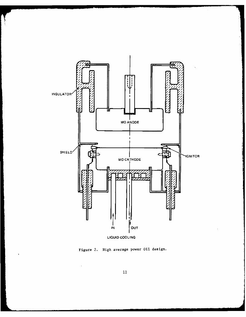
Section IV discusses the design of a high average power switch (Fig. 2)
which takes these considerations into account. The switch design uses 1-kg
molybdenum electrodes to increase the heat-sinking capability and to limit the
flow of inverse current. A large cathode surface area is water cooled to
provide additional heat rejection during operation. A sputter shield is
extended partially over the ignitor and cathode electrodes to break the Paschen-
breakdown path below the ignitors and partially protect the ir itors. The
insulators are backed away from the arc region and are convol 1 to further
reduce the effects of sputtering. Multiple ignitors are incl i to extend the
lifetime of the device. The overall weight of the tube desig less than 3
kg and it is less than 2000 cm3 in volume. Water or thermoelt _c cooling of
the anode is optional, depending on the usage. Trigger enengy is less than 30
mJ per pulse. No keep-alive, heater or other auxiliary power is required.
9

TABLE 1. OPERATIONAL 011 EFFECTS AND DESIGN CONSIDERATIONS
TRIGGER EFFECTS
KME'IANISM EFFECT CURE/RESULT
Thermal instability in semi- Trigger overheats Lower trigger energyconducting ignitor trigger
Delay time increased Heat sink trigger
RMS-Jitter > 300 no RMS-Jitter < 20 as
Run time < 90 s Run time >> 180 s
Start up jitter due to Temperature of cathode Establish thermalpressure changes increases causing mercury equilibrium as rapidly
vapor pressure increase as possible
Heat sink electrodes
Delay time decreases Preprogram delay ofthen stabilizes early pulses
Multiple Ignitors Less power per ignitor/ No advantagemore Lgnitors
HIGH POWER EPFECTS
Cathode heating Increases mercury vapor Increase electrode
heat capacity
Paschen breakdown Increase cooling power
Reduced recondensation rate Increase mercuryof mercury volume
Mercury starvation on cathode Use molybdenum anode
Jitter/failure to fire
Accentuated by inverse
current
Contamination Outgassing High vac um pre-processing
Paschen breakd,-wn
Sealed-off untsReacts with surface ofmercury film Use high purity
componentsBlocks migration of mercury
Mercury starvation
Jitter/failure to fire
Multiple Ignitors Extend active region when Space 2 cm apartsurface partially mercury
starved
Sputtering Insulator coating Add sputter shield
Voltage hold-off failure Convolute insulator
Accentuated by inverse Back insulator awaycurrent/anode arc spotformation Heat-sink anode
Use molybdenum anode
10
oo,/,
S L / M O C A H D - - G N T O
X , /
I OUT 7
LIUI COOLIN
Fiur 2. Hihaeaepwe/1ein

II. TRIGGER STABILITY
The 011 has trigger characteristics comparable to conventional ignitrons.
This section reports on advances in the design and operation of the ignitor
electrode and in the trigger circuit which allow the 011 to operate with jitter
of less than 0.2 P~s at repetition rates in excess of 100 p/s and run periods of
over 3 min. The jitter and trigger instability are related to (1) thermal
variations in the semiconducting-ignitor resistance, (2) a rapidly varying
voltage-time characteristic for trigger-arc development across the ignitor tip
and (3) a pressure-voltage characteristic for the development of the main arc
across the anode-to-cathode gap.
The passage of current through the conical ignitor to the mercury contact
point has two effects. High electric fields are generated along the surface of
the semiconductor, and both the semiconductor and mercury are ohmically heated.
Boath effects are strongest at the contact points; electrons and ionized mercury
vapor are emitted from the contact point. This emission of plasma is limited
and is not sufficient to,produce anode conduction by itself. However, if the
electric field exceeds a threshold value for a sufficiently long time, an
avalanche develops along the ignitor tip to the supporting metallic structure
and a cathode-arc spot forms, increasing the emission of plasma from the
cathode. It is the formation of this ignitor arc that leads to the breakdown of
the main anode-to-cathode gap. The anode-fall time is also an avalanche process
and depends on the background pressure, which, in turn, is related to the
cathode temperature.
If successive or excessive pre-arc ignitor currents heat the semiconducting
tip, the resistance of the tip falls and the voltage drop across the ignitor may
not be sufficient to initiate or sustain an arc. In this event, a relatively
large amount of charge may pass through the ignitor without anode conduction
taking place. By reducing the ignitor-power loading and improving the ignitor-
heat rejection capability, it is possible to increase the repetition rate by
orders of magnitude while reducing the switch jitter by an order of magnitude.
While conventional practice would dictate a trigger energy of about 2 J,
triggering is most reliable with trigger energies of about 30 n.J.
12

t.. EXPERIMENTAL APPARATUS
The major components of the experimental apparatus consist of two models
(denoted 011-2 and 011-3) of the Orientation Independent Ignitron (011) and
their test circuit. A cross-sectional view of 011-2 was shown in Figure 1.
This is a single-ignitor 011. The cathode is made of molybdenum and is
supported by thermally insulating stainless-steel cylinders. The cathode is
cooled by a copper rod, attached to the cathode at one end, with the other end
encased in a cooling coil. The ignitor is attached to an adjustable rod so
that the ignitor tip-to-cathode spacing can be adjusted. The ignitor tip
typically consists of molybdenum. The anode is supported on a ceramic bushing
and shields are attached around the ceramic to both protect the ceramic from
deposits of sputtered material and to prevent Paschen breakdown.
A cross-sectional view of the 011-3 is shown in Figure 3. This is a
multiple-ignitor 011. Seven ignitors are positioned around the outer diameter
of the cathode. Again the ignitor tips are carbide and the cathode is
molybdenum. The ignitors are supported from the cathode assembly. This
provides a means of keeping the ignitor tips in contact with the cathode at the
required pressure and also cools the ignitors by thermal conduction to the
chilled cathode. This cathode is also cooled with a copper rod attached to a
cooling coil. The shields around the ignitors and the anode cylinder provide
some protection against both sputtered material and Paschen breakdown. Both of
these experimental models of the 011 were fabricated using demounted flanges.
Figure 4 is a photograph of the 011-3, which also show~s the mercury-fill and
pump-out plumbing.
The basic test circuit and typical component values are shown in Figure 5.
The rise time of the ignitor current is determined by both the No. 6279 hydrogen
thyratron and inductance of the loop through the thyratron, capacitors and
ignitors. The approximate inductance of this loop is 3UH. The inductance of
the anode loop is about 0.5 PHi, which determines, in part, the rise time of the
anode current. The anode capacitor was increased from 0.1 to 4 OiF to lower the
* loop impedance for high current (15 kA) measurements. The dc current limit
13

ANOO
CON LA~g7 1/4 IN
Cu COOLING I
0 L
~ 4 1/2 IN DIA
Figure 3. Cross-sectional view of 011-3.
14

Figure 4. 011-3 completed assembly showing mercury-fill and pump-out plumbing.
Oil 100 U2l
527 \- CANODE~
7-70p 7INIO
CAPACITORS
Figure 5. Test circuit for Ols.
15

for the anode power supply is 0.2 A. The current in the anode circuit rings,
and this results in a net average anode current an order of magnitude higher
than the power supply current. The test system instrumentation includes an
image converter camera, current transformers, high-voltage probes, and
temperature and pressure sensors.
2. LOW POWER TEST RESULTS USINIG A CONVENTIONAL IGNITOR SYSTEM
The jitter behavior of the Ott was examined using a conventional ignitor
system design (1-PF, 25-UH trigger circuit) and have determined that the key
source of jitter is due to the negative coefficient of resistance which is
characteristic of the semiconductor ignitor tip. Switching operation, even in
the absence of anode voltage, heats the ignitor material until its cold
resistance of -10 Qi falls below 1 Q. At this point, the semiconductor begins
to run-away thermally and effectively shorts out.
The heat capacity and conductivity of the ignitor are finite so that there
is a normal run time during which jitter may be lowi before the switch begins to
misfire. The actual run time is subject to several sources of variation:
contact pressure, position, Hg wetting, and initial temperature. All of these
affect the initial resistance and cause fluctuations in the stable run time of
the switch.
Direct current measurements show that at powers of over 1 W, the i-nitor
resistance falls; the ignitor voltage does not rise above about 3 V in the
steady state. The thermal time constants are about 15 s.
Under pulsed conditions (Fig. 6), thermal equilibrium is ot reached and
the voltage can rise considerably higher than for the case of dc operation. The
measured ignitor voltage starts off as though it were resistive, and it remains
so as long as the voltage does not exceed about 40 V.* During this period, only
a small, dim source of light Is observed at the ignitor tip and anode conduction
does not take place. At voltages approaching 80 V, a flashover is coincident
with both the formation of a cathode spot and a drop in the ignitor voltage.
The flashover appears to be essential for proper anode conduction and any jitter
in its formation leads directly to jitter in the anode time-delay. The proper
waveform that triggers the Ott into anode conduction is that of Figure 6b.
*This is only a typical value but different ignitor tips will scale in thisgeneral fashion.
16

100-z
S 50-
0(a) Ignitor current 50 A/Division (D).
FLASHOVER LEVEL60 60
(D 40-
o 20
(b) Ignitor voltage - ignitor "cold" 20 V/D.
S 60 --- FLASHOVER LEVEL
wU0< 40-
0> 20-
0 1 2 3TIME (A s)
(c) Ignitor voltage - ignitor "hot" 20 V/D,600 ns/D.
Figure 6. Pulsed ignitor characteristics.
17

As the ignitor heats from pulse to pulse, the peak ignitor voltage reduces until
it fails to teach the flashover level (Fig. 6c) and erratic anode behavior
ensues.
3. JITTER TIKE CORRELATION BETWEEN PULSES
An analysis of the pulse-to-pulse correlation in anode-fall delay time has
been made for a conventional ignitor system for two runs at approximately 0.5
and 1 Hz. This delay time is defined as the period from the start of the
ignitor voltage waveform to the start of anode conduction. At the lower
repetition rate, the jitter time a (defined as the root-mean-square deviation)
is 0.35 us. As the repetition rate is increased, a increases to 0.79 us.
Detailed analysis of the data shows that the delays are not normally
distributed. A strong pulse-to-pulse correlation (i.e., memory of the previous
pulse) is seen which lasts up to about 6 pulses (Fig. 7). The plot of Figure 7
shows the autocorrelation function which was made using 124 observations of
delay times. Samples of 10 sequential data points were incrementally correlated
with the remaining data points. Then, using the definition given by Reference
2, the next sample of 10 data points was Indexed along the data list, and the
correlation was repeated.
Based on these data, the purely random statistical component has a jitter
of (<0.3 us which is superimposed upon a much larger thermal drift. The latter
has a correlation time of 6 pulses or about 6 s. This is consistent with the
measured ignitor temperature stabilization time of 15 s.
4. TEST RESULTS WITH A MODIFIED IGNITOR SYSTEM
The characteristics for avalanche breakdown along the surface of the
ignitor are observed to be similar to other systems where a threshold voltage
(VT) is required for arcing to take place. As the trigger voltage (V) is
increased beyond VT, both the time delay (At) for ignitor arc development and
the jitter decrease. This implies that (V - VT) x (At) must exceed a
characteristic level, which is about 5 x 10- Vs.
2. D.N. Menzel, Fundamental Formulas of Physics, Vol. 1 (DoverPublications, Inc., New York, NY, 1960), p. 85.
18

1.2
1.0
zu'0.8U.LLU-
0
z 0.60
_-
x,0.40*
0.2
0.00 2 4 6 8 10
TIME,s
Figure 7. Interpulse correlation coefficient for jittertime for 124 observations using sample datataken at 1 and 2 Hz, using a conventionalignitor system.
Typically, the trigger circuit has a higher impedance than the ignitor, the
current rise is circuit limited, and the voltage rise at the ignitor depends on
the resistance (R) of the ignitor tip. Resistive heating of the ignitor depends
on the temperature coefficients of the semiconductor and the design of the
supporting structure. It was found empirically that during single-pulse
operation the voltage first rises linearly with the current and then drops
19
rapidly as the resistor heats. For slow-rising pulses the resistance drops
gradually early in the pulse due to Joule heating. The voltage never reaches
VT and triggering does not take place (Fig. 8c). Likewise, for very fast
pulses the voltage exceeds VT, but the resistance falls very fast and the
voltage decreases below VT before the avalanche time occurs (Fig. 8a). Proper
triggering is shown in Figure 8(b) where the voltage exceeds VT for a period
long enough for an avalanche to take place, at time - tarc. Measured
values of the ignitor-arc delay (At) are shown in Figure 9 as a function of the
peak ignitor voltage at 100 p/s. The trigger behavior is found to improve for
smaller trigger-source capacitors which are charged to higher voltages.
5. REPETITION RATE EFFECTS (TRIGGER)
The effect of increasing the repetition rate of the trigger is to decrease
the initial resistance due to heating. This reduces the stable operating range
of the trigger-charging voltage and is most evident for larger capacitors. For
these reasons a capacitor size of 0.0027 UF and an operating trigger voltage of
about 5 kV were chosen.
Reliable steady-state operation of the ignitor was achieved at pulse-
repetition rates up to 300 p/s. The steady-state trigger jitter at this
frequency decreases to less than 20 ns. Start-up jitter is about 100 ns, due to
thermal relaxation and is consistent with the low-repetition-rate correlation of
6 pulses.
6. ANODE CONDUCTION BEHAVIOR
The peak current capabilities of the test-model Oils were investigated
using a 4-UP capacitor in the anode circuit. Typical test results are shown
in Figure 10. The anode current at 20 kA/Division (D) measures -18 kA for an
anode voltage of 10 kV (5 kV/D). These data are for low repetition rates
(essentially single shot).
High-repetition-rate data were taken up to 300 Hz. The ratings of the
laboratory dc supplies limited the high-repetition rate data to lower powers.
Typical oscilloscope traces for the anode voltage and current at 100 Hz are
shown In Figure 11 using a 0.1-UP trigger capacitor. Alternate scope sweeps
2u

FALLINGRESISTANCE
uJ PHASE
0> AVALANCHEccO PHASE0
~--VT
tarc
TIME
(a) A fast rising current pulse pro-duces rapid heating, the voltagepulse is high but too short to arc.
(b) Intermediate rise time where theresistive fall is delayed andarcing has sufficient time todevelop.
(c) Slowly rising pulse where thevoltage does not exceed a thresholdfor arc formation. Condition (b)is required for anode conduction.
Figure 8. Characteristic conditions for externalavalanche breakdown along the ignitor.
21
II

TRIGGER SOURCE60 CHARGING CAPACITANCE6 VOLTAGE
2 149) 1pF250V 3 0.1 W~F
>- 400 \Q5kV * 0.007.
300 4kV% 125 kV
< 200 %
0. 4-6kVVx (4 = CONSTANT
0 I I0 500 1000
PEAK IGNITOR VOLTAGE (V)
Figure 9. Ignitor arc delay time.
were used and several hundred traces are recorded, which represent operation for
several seconds, near the end of a 90 s run. (The initial pulses of a run are
not shown; due to circuit and thermal transients these are of greater amplitude
and have more jitter.) The anode power supply is set at 10 kV; but the
resistance-capacitance (R-C) charging time-constant is 10 ms, therefore the
voltage reaches only about 6 kV, and the anode current is 2 kA. The jitter is
about 35 ns for both the anode fall and current rise. Here, the time span at
half amplitude that encompasses all the data (or 4100 pulses) is taken to
be 6a.
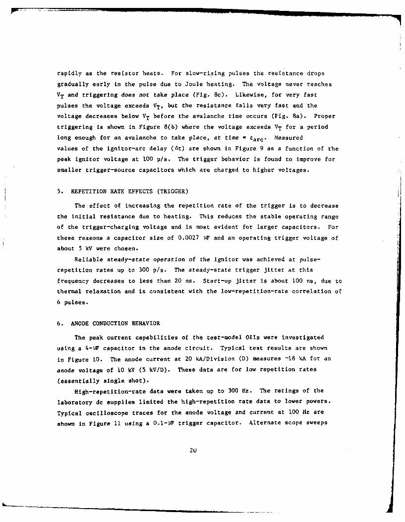
The anode-current-rise time is determined both by the test-circuit
parameters and the 011. In Figure 12 the anode-voltage fall and current rise
are shown at low repetition rate. The ignitor pulse is applied at a time,
t - 400 ns, as can be observed on the traces by the noise burst at this time.
The anode current rises exponentially from this time (400 as) to about 1 Us. At
this point (1 ls), the exponentially increasing current blends into the current
22

Figure 10. Operation at peak anode current of 18 kA.
Anode current (top) at 20 r , n ancdevoltage (bottom) at 5 I'V/D, 2 4S,'D.
Figure 11. Operation at 100 H7. Anode voltage (top traces)
at 5 kV/D; anode current (bottom) at 1 kA/D;100 ns/D. Showing an rms jitter of approximately35 ns. Trigger capacitor 0.1 LF.
23
0 400 1000
TIME (ns)
Figure 12. Anode voltage fall and current rise.
Top - voltage at 5 kV/D.
Bottom - current at 1 kA/De
200 ns/D (single pulse).
as lnited by the inductance-capacitance (L-C) ringing characteristic( ,t ,ce
test circuit. At this time, the maximum di/dt approaches 101 0 A's-1 . The
exponentially rising-current may be expressed as I = 1o eYt where Y =
10 /s-1. The growth rate, Y, increases significantly with the background mercury
pressure, typically produced by high-repetition-rate operation.
7. MULTIPLE IGNITORS
One objective of this 011 development program was to study triggering
characteristics as a function of the number of ignitors, the idea being to
decrease jitter and increase triggering reliability with multiple ignitors.
Some results are presented in Figures 13 and 14. Figure 13 shows anode voltage
and current for operation with a single ignitor (a), for three ignitors (b),
24

(a) For one ignitor.
(b) For three ignitors.
(c) For seven ignitors.
Figure 13. Jitter as a function of the number of ignitors in use.
25
Mk_ _ _ww

1.0 I I IJITTER DELAY
___ At0.9 0 1 IGNITOR
O ® 7 IGNITORS0.8 \ 0 * 3IGNITORS
0.7 -
0.6 \" A0 Z \At
0.5
0.4 -
0.3
0.2 o
0.1
01 2 3 4 5 6 7
IGNITOR CAPACITOR VOLTAGE, kV
Figure 14. Low-repetition-rate jitter (a) and delay (At)times as a function of ignitor capacitorvoltage. Data averaged over 5 pulses. Initialanode voltage of 12 kV.
26
and for all seven ignlitors (c). These are low repetition rate data at Va . 10
kV and la = 3.5 kA. Evidently there is no significant improvement in
performance by adding additional ignitors at relatively low average power.
Figure 14 shows both delay time and jitter as a function of Ignitor-capAcitor
voltage for the three cases of one ignitor (a), three ignitors (b), and all
seven ignitors (c). Both delay time and jitter reach a minimum for ignitor-
capacitor voltage of 4 to 5 kV and, within experimental error, the data for the
multiple ignitor cases falls within the same range as that for the single
ignitor case.
8. REPETITION RATE EFFECTS WITH ANODE CURRENT
A series of measurements (Fig. 15) shows the decrease in jitter with
increasing repetition rate. A trigger capacitor of 2700 pF was used. The
steady-state jitter decreases appreciably from 33 ns; at I THz to essentially zero
on this scale of 200 nsID at 30 Hz. The jitter remains low at 60 and 100 Hz.
The observation is that the temperature of the components and the Hg pressure
increases and stabilizes during the runs at the higher repetition rates. This
stabilization of the temperature and pressure is instrumental in the decrease of
jitter. If the pressure in the 011 is Increased by operation at high repetition
rate and followed by a reduction in the repetition rate to I Hz, the jitter
remains low, as shown in Figure 16(a). Decreasing the pressure to its normal
value of -'1.5 x 10- torr by pumping while hot, the jitter increases to near its
previous value at 1 Hz, as shown in Figure 16(b).
9.* SUMHARY OF TRIGGER IMPROVEMENTS
The primary trigger mechanisms leading to jitter, delay time, and switch
instability at low average power have been identified in ignition type devices
using mercury wetted cathodes called orientation independent ignitrons. This
work has indicated the need to heat sink the ignitor electrode and limit the
energy in the trigger pulse to exceptionally low levels by using higher voltages
and shorter trigger pulses. These concepts were applied to the design of the
ignitor and the trigger circuit and resulted in a significant improvement in
switch behavior.
27

(a) At 1 Hz. (b) At 3 Hz.
(c) At 10 Hz. (d) At 30 Hz.
Figure 15. Jitter as a function of pulse repetition rate.
Top traces, VA at 5 kV/D. Bottom traces, 1A at1 kA/D. 200 ns/D; 10 pulses are recorded on eachfigure.
Essentially steady-state operation can be maintained at frequencies beyond
300 p/s at low average power (-6 kW average) with jitter times much less than
20 ns. The jitter is higher during start-up transients and stabilizes as the
temperature of both the ignitor and the mercury stabilize. The anode fall-time
can be treated as due to an exponential growth of current. The exponential
growth rate of the current is on the order of 10 7 s - I at a pressure of 2 x 10- 3
torr, corresponding to a starting cathode temperature of 13'C. The grcwth rate
Is automatically increased by operating the switch repetitively and increasing
the mercury pressure.
28

(a) Pressure equals 6 x 10 -3 torr.
(b) Pressure equals 1.5 x 10- 3 torr.
Figure 16. Jitter as a function of OIT
Hg pressure. Anode currentat 1 kA/D, 200 ns/D; 10 pulsesare recorded on each figure.
29

III. RIGH AVERAGE POWER TESTS
Section II discussed low-average-power tests at Hughes Research
Laboratories (HRL) which show that Oils can be made to operate with low jitter
(a 2 30 ns). The test limits were 30 kV, 15 kA, and 100 Hz, but these are not
simultaneous data. For example, the low jitter data were obtained at low
voltage and current, and the 15-kA data were obtained at low voltage. Based on
these results, the Oils were judged ready for high-average-power tests. The two
test model Oils were subsequently tested at the high-average-power facility at
'Kirtland Air Force Base (KAFB), New Mexico. Low-jitter data were again obtained
for anode currents of 1 kA. At higher power, unstable 011 operation resulted
from a failure to hold voltage on recharging and failure to fire on every pulse.
Sections III-1 and 111-2 discuss the tests and the mechanisms responsible for
the observed behavior.
I. HIGH POWER TEST RESULTS USING 011-3
011-3 is the multiple-ignitor tube described in Section II. Two out of
seven ignitor feedthrough bushings were found to be broken following shipment to
the test site. These were removed and the holes were closed with epoxy. A
vacuum system was arranged to pump out the tube. Cooling water for the cathode
was provided using an ice bucket and pump. Typical initial test results using
the high-average-power facility at KAFB are shown in Figures 17 and 18. These
oscillograms show pulses accumulated on a storage oscilloscope during a 90-s run
at 100 Hz. Shown in Figure 17 is the 1-kA, 28-us anode-current pulse. in
Figure 18 the time base has been expanded to 200 ns/D, and the current rise
shows low jitter (full width of 180 ns or rms deviation of a = 30 ns).
During the early testing the tube showed a gradual improvement in behavior
with current conditioning, presumably due to clean-up of contaminants.
But, then as the anode voltage and currrent were increased, the jitter first
increased by approximately an order of magnitude and then the OTI failed to
recover properly, as shown in Figure 19. In this figure, the anode voltage is
shown at 5 kV/D and 1 ms/D. Although the 01 recovered properly on most
30

Figure 17. Anode current pulse, 1 kA x 28 zs, 400 V'D, 5 .s/D.
Figure 18. Anode current rise showing jitter at 100 Hz for a90 a run periodi, 400 AID, 200 ns/D, T- 30 ns.
31
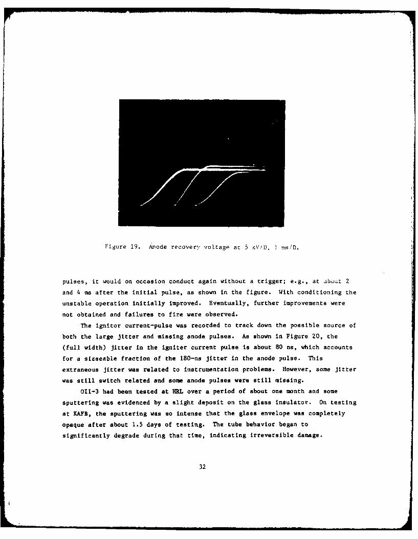
Figure 19. Anode recovery voltage at 5 KV!D. 1 rns/D.
pulses, it would on occasion conduct again without a trigger; e.g., at about 2
and 4 ms after the initial pulse, as shown in the figure. With conditioning the
unstable operation initially improved. Eventually, further improvements were
not obtained and failures to fire were observed.
The ignitor current-pulse was recorded to track down the possible source of
both the large jitter and missing anode pulses. As shown in Figure 20, the
(full width) jitter In the igniter current pulse is about 80 ns, which accounts
for a sizseable fraction of the 180-ns jitter in the anode pulse. This
extraneous jitter was related to instrumentation problems. However, some jitter
was still switch related and some anode pulses were still missing.
011-3 had been tested at HRL over a period of about one month and some
sputtering was evidenced by a slight deposit on the glass insulator. on testing
at KAFB, the sputtering was so intense that the glass envelope was completely
opaque after about 1.5 days of testing. The tube behavior began to
significantly degrade during that time, indicating irreversible damage.
32

Figure 20. Igniter current pulse at 100 AID, 200 ns/Dshowing residual trigger source generatedjitter.
2. HIGH POWER TESTS OF 011-2
Next, the single-igniter tube, 011-2, was evaluated. The test results are
summarized by referring to Figures 21, 22, and 23. In Figure 21, the anode
current was found to alternate between two types of operation, a single forward
pulse, and a ringing pulse. The conduction in the reverse direction is due to
circuit impedance mismatch.
Figure 22 shows the anode recovery characteristics of 011-2- The switch
continues to conduct for 1 msec or more on some pulses, indicating an outgassing
problem. Operation was attempted at a 30-Hz rate, but before the end of a 90-s
run period the tube began to fail to fire, as shown by the base line on the
current pulses of Figure 23. The failures to fire were similar to those in O11-
3 and the experiments were terminated.
3. ANALYSIS OF THE CATHODE SURFACE
* The Olls were dismantled for analysis. The cathode of 011-3 is shown in
Figure 24. The lead to igniter No. 2 was found to be open; igniter insulators
* ~ Non. 6 and 7 were broken in shipment to KAFB, hence they were inoperable.
33
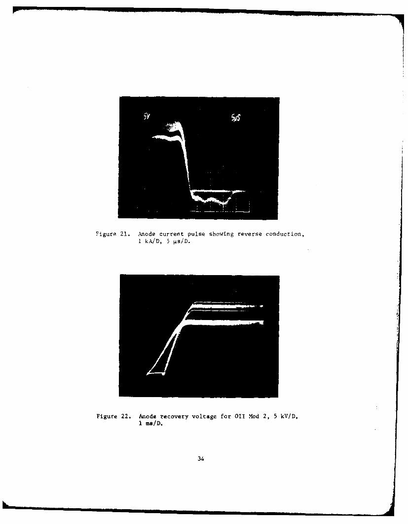
Figure 21. Anode current pulse showing reverse conduction,I WAD, 5 4~s/D.
Figure 22. Anode recovery voltage for 011 Mod 2, 5 kV/D,1 msiD.
34

Figure 23. Anode current pulse showing missing pulses,200 A/D, 5 ps/D.
Figure 24. Cathode for 011 - Mod 3, showing Hg depletedarea (light region) and contaminated Hglayer (dark region).
35

Igniter No. 8 was not installed initially. The light (or active) region of the
cathode is relatively Hg-free. The dark areas adjacent to the inoperative
igniters Nos. 2, 6, and 7 were heavily coated with contaminated Hg. The cathode
surface was studied with Auger electron spectroscopy; the dark area is
apparently carbon coated in addition to being Hg coated. This carbon appears to
inhibit the necessary diffusion of the Hg over the cathode surface to the
regions near the active igniters.
4. DISCUSSION OF RESULTS
A 200-atom layer thickness of Hg is needed per pulse on the basis of only
one electron emitted for each Hg ion evaporated. However, some estimates for
the electron-to-ion ratio are as high as 50. It appears practical to deposit a
sufficiently thick layer of Hg onto the cathode to supply Hg for the desired
9000 pulses. For a cathode held at O'C, the recondensation rate of Hg onto the
cathode is sufficient to pump out the Hg used during the pulse in a small
fraction of the interpulse period. Therefore, it should be possible to obtain
the desired voltage recovery characteristics as long as the cathode temperature
is maintained. Our previous thermodynamic measurements at ERADCOM (Ref. 1)
showed the cathode temperature to be normally limited to less than 60'C.
Mercury starvation at the cathode could increase the heat loading beyond the
safe limits, causing Pachen breakdown.
The questions arise as to why the Hg was carbon-coated and why breakdown
occurs just after a pulse. Vacuum problems were experienced with both of these
tubes - one was opened to air by the breakage of the ignitor insulators, while
the other was opened to air by an arc at the high-voltage anode bushing. These
tubes had been opened to air previously and reevaluated without deterioration of
operating characteristics at low average power. High powers may Increase the
outgassing rate of hydrocarbons used to repair the damaged components,
particularly if current reversal produces arc spots on the anode structure.
Voltage breakdown just after the pulse may be related to both the pressure
increase during the pulse (cracked hydrocarbons would not recondense rapidly)
and the relatively large gap between the Paschen breakdown shield and the
ignitor supports. Possibly, Paschen breakdown occurs from the anode, through
this gap, to a region behind the cathode - a long path for a large pressure
distance (P-d) product.
36

5. SUMMARY OF HIGH AVERAGE POWER TEST RESULTS
Switch jitter and tube failure-to-fire at high repetition rates were
originally identified as due to the ignitor-trigger-system design. These
trigger problems have been corrected during the present program. Additional
sources of switch instability have now been identified which only occur at high
average power. These are mercury starvation due to excessive heating of the
cathode, lack of migration of mercury due to contamination, and over
pressurization due to contamination. The cathode region reached by a single
ignitor appears to be a circle about I cm in radius, indicating that multiple
ignitors may be necessary for high average power operation if the necessary Hg
recondensation rate cannot be obtained.
I
-' _37
IV. DESIGN CONSIDERATIONS FOR A HIGH AVERAGE POWER 011
To capitalize on the increased understanding of 011 operation resulting
from the present program and take full advantage of the 011 switch for potential
military application, an 011 design such as the one shown in Figure 2 should be
developed which uses the multiple-ignitor design, eliminates the vacuum-leak
problems, and maintains clean, uncontaminated Hg. The ignitor-shield gap should
be closed up to improve the voltage-breakdown behavior. An increased Hg fill
should be used and the cathode should be chilled to a lower temp-arature (near
O'C) for the purposes of providing sufficient Hg to solve the missing pulse
problem and to help with the voltage-breakdown problem. The anode should be
made of molybdenum to increase the chopping level for inverse currents and
to decrease the back sputtering during current reversal. The insulators should
be moved away from the arc to protect them. Under high current operating
conditions, the power loading of the present cathode may reach 200 W. In a run
time of only 15 s the cathode temperature may rise beyond 38'C and the mercury
vapor pressure will exceed the Paschen breakdown limit. Therefore, the heat-
sinking capability of the cathode structure should be increased by an order of
magnitude by adding additional cathode material and copper to the heat-conductor
assembly. A mass of 1 kg at the anode and at the cathode should significantly
increase the stable run time of the 011 to over 90 s. The 011 design shown in
Figure 2 incl'xdes these improvements.
38