activpilot control
TRANSCRIPT

activPilot ControlThe new generation of locking sensors.
in windows
Product Catalogue 01/2012


Table of contents
General product information
Page 3 - 7General product
information
Basic technical features
Pages 8 - 9Basic technical
features
RFID locking sensor
Pages 10 - 11RFID locking sensor
RFID contactor
Pages 12 - 14RFID contactor
Magnetic locking sensor
Pages 15 - 18Magnetic locking
sensor
Magnetic contactor
Pages 19 - 21Magnetic contactor
Mounting jig / Test device
Pages 22 - 23Mounting jig / Test
device
Installation Instructions
Pages 24 - 30Installation
Instructions
Function test locking sensors
Pages 31 - 33Function test locking
sensors
General product informationWinkhaus activPilot Control 3 Print-no. 996 000 280 / 0112 GB
2
3
4
5
6
7
8
9
1
Mounting jig /
Test device
Function test
locking sensors
General product
information
Magnetic
contactor
Basic technical
features
RFID
locking sensor
RFID
contactor
Magnetic
locking sensor
Installation
Instructions
Aug. Winkhaus GmbH & Co. KG · August-Winkhaus-Str. 31 · D-48291 Telgte · T +49 (0) 25 04-921-0 · F +49 (0) 25 04-921-340 www.winkhaus.de
1General product
information

Recognitions from over 150 years of development work:
a new system of fittings
activPilot: The new standard of turn-tilt fittings
Developing a new system of fittings from the initial drafts to market maturity is a time-consuming process. It is not just a question of creative ideas, precise calculations and countless series of tests, but also of intensive monitoring of people and markets, evaluating current trends and ongoing analysis of general technical developments. We even question tried and trusted approaches to be able to leverage all this information, and apply our years of experience to create targeted, premium solutions that offer fitters and users a whole new range of op-portunities. Both from an economical and functional point of view. It is this constant drive towards precision that has made Winkhaus one of the leading enterprises in the field of window and door technology. This is evident by the large number of industry standards that Winkhaus has established in over 150 years.
From established standards to the next generation standard
In designing activPilot we created all the solutions needed for the next-generation window fitting standard within a single sys-tem. An intelligent, clearly-structured modular system with far less components than was previously typical, activPilot meets all your requirements from a modern range of fittings. activPilot is suitable for any shape of window, any window material and any level of automation, from manual mounting to fully automa-ted serial production. The high level of flexibility, the attractive auxiliary functions, the new locking system and the functional design all ensure that your business is perfectly geared today to meet your customers’ needs and future requirements.
Modular design
activPilot optimises window construction. For the window buil-der, less components and multifunctionality mean uncompli-cated and fast processing and rational mounting. Premounted components and the unique design furthermore ensure that additional functions and safety classes can be achieved easily by retrofitting. activPilot thus sets the scene for sustainably cut-ting your production, warehousing, logistics and administration costs.
New locking system with octagonal locking bolts
activPilot enhances comfort. The functionally perfect locking mechanism not only guarantees precise entry of the locking bolt into the frame keep, but also a perfect seal. This is ensured by the excellent air gap tolerance of 9.8 to 14 mm and the new octagonal locking bolt which allows easy manual adjustment of the contact pressure. Even adjusting forces and the non-positive and positive system fit of the components give this fitting the required stability and long-term functionality.
Add-on functions
activPilot gives you the ability to react flexibly to customer re-quests. Innovative multi-purpose components make it easy to retrofit features at any time. The use of a duo and/or tri func-tional element makes it simple to add a fail safe device with integrated limiter support and balcony door catch. The variable tilt device supports different sash tilt angles and thus fast, easily adjustable ventilation settings.
Design
activPilot offers you and your customers real added value. Surprising details, discreet accents, ergonomic design and com-prehensive functions characterise the overall concept of the fit-ting system. In short, its attractive design will be a crucial factor when it comes to your customers making a purchase decision. activPilot also offers other convincing arguments such as out-standing durability, easy-to-clean surfaces, intuitive operation and, last but not least, aesthetically pleasing windows.
Effective security
Thanks to the unique modular system, any window can be modified to achieve the required security standard – easily, quickly and cost-efficiently. There is no need for custom parts. Depending on the number and type of keeps, various security levels are achievable using the same platform. At our works, comprehensive and strict tests – along with on-going functional monitoring – ensure maximum security for customers. Approval marks and certificates by independent test authorities confirm our results. You can therefore rely on activPilot meeting customer requirements for a secure fitting system. Locking bolts are made of high-strength steel; even standard types guarantee effective basic security. Depending on the number and type of keeps, the fitting system can be en-hanced for compliance with stricter security classes – including burglar protection to DIN V ENV 1627-1630, resistance class 2 / DIN EN 1627–1630, RC2.
Your partner for service
Our services are solution-orientated, reliable and precisely ge-ared to match your requirements – just as you would expect from your partner. We are always at your service. With applica-tion engineers on site, professional help from our product data service, and innovative software solutions to help optimise your workflow we safeguard and extend your capacity to act. On top of this, our comprehensive product information system and so-phisticated logistics service guarantee fast delivery at all times.
General product informationWinkhaus activPilot Control
2
3
4
5
6
7
8
9
1
4 Print-no. 996 000 280 / 0112 GB
1
Aug. Winkhaus GmbH & Co. KG · August-Winkhaus-Str. 31 · D-48291 Telgte · T +49 (0) 25 04-921-0 · F +49 (0) 25 04-921-340 www.winkhaus.de

Quality standard
The Winkhaus group successfully passed a group certification of production sites according to DIN ISO 9001:2008.The group certification ensures that we use the same criteria and procedures in all Winkhaus subsidiaries und thus we can always offer consistent quality for our customers.
Product liability
To ensure compliance with German product liability laws (ar-ticle 4 ProdHaftG), please observe our manufacturer’s informa-tion on turn-tilt fittings for windows and glazed doors. Failure to observe releases the manufacturer from any liability. Please consult your Winkhaus contact person for further information on this topic.Information on Winkhaus product services as well as specifica-tions and instructions for end users have been specially summa-rised in the “Product Information and Processing Instructions” brochure. Please also observe the guidelines issued by Gütegemeinschaft Schlösser und Beschläge e.V. (Association for Quality Control of Locks and Fittings). This information can be obtained at the following Internet addresses: http://www.winkhaus.de (Products & Services/Notices about products and liability) or http://www.beschlagin-dustrie.de/ggsb/richtlinien.asp
activPilot Control
In Germany, about 380,000 burglaries happen per year. From a statistical point of view, this means there is a break-in every two minutes, with burglars mainly entering through windows or patio doors. It’s not only luxury mansions which are affected by such crimes – family homes and flats in apartment buildings are too. Only one in five cases of burglary is solved. Protecting property requires more effective burglary resistance and sur-veillance systems. Winkhaus offers an unrivalled solution – ac-tivPilot Control.
Locking surveillance based on magnetic contacts:
Unobtrusive closing sensors reliably report which windows and glazed doors are open or locked. At the same time heating and air-conditioning controls are supported.The locking sensors are system-independent intrusion detec-tors designed for surveillance which can be combined with all standard alarm systems.The magnet signal contacts have been approved by VdS Schadenverhütung GmbH and certified to VdS class B.
Locking surveillance based on RFID contacts:
Winkhaus has developed a new dimension in window surveil-lance systems with a pioneering technological design for win-dow fittings – the fitting-integrated lock sensor with RFID trans-ponder technology. Unique on the market, this window fitting replaces the standard magnetic alarm contact in such systems by an RFID-controlled lock sensor.This technology significantly increases the protection from sa-botage and manipulation of the locking control device. The RFID signal contacts have been approved by VdS Schadenverhütung GmbH and certified to VdS class C.
General product informationWinkhaus activPilot Control 5 Print-no. 996 000 280 / 0112 GB
2
3
4
5
6
7
8
9
1
Mounting jig /
Test device
Function test
locking sensors
General product
information
Magnetic
contactor
Basic technical
features
RFID
locking sensor
RFID
contactor
Magnetic
locking sensor
Installation
Instructions
Aug. Winkhaus GmbH & Co. KG · August-Winkhaus-Str. 31 · D-48291 Telgte · T +49 (0) 25 04-921-0 · F +49 (0) 25 04-921-340 www.winkhaus.de
1General product
information

Further products
activPilot Concept
The turn-tilt fitting for PVC-U windows.
A modular system that combines the solutions of a future stan-dard. A new closing system, attractive value-added functions and functional design.
activPilot Select
The new fully concealed turn-tilt fitting.
The fitting system features fully concealed shear, turn and corner hinges housed in the rebate. When installed as a standard model, this elegantly designed turn and tilt fitting is able to bear sashes weighing up to 100 kg. With just two additional components, it can easily support sashes weighing up to 150 kg.
activPilot Comfort PADK
Turn-tilt fittings with parallel action.
Allround security thanks to innovative technology. The convenient approach to a healthy indoor atmosphere and improved illegal ent-ry protection in parallel position.
General product informationWinkhaus activPilot Control
2
3
4
5
6
7
8
9
1
6 Print-no. 996 000 280 / 0112 GB
1
Aug. Winkhaus GmbH & Co. KG · August-Winkhaus-Str. 31 · D-48291 Telgte · T +49 (0) 25 04-921-0 · F +49 (0) 25 04-921-340 www.winkhaus.de

activPilot Comfort Ergo
The ergonomically controlled turn-tilt fitting.
Actuating the handle tilts and returns the sash. Due to this intel-ligent controlled action, there is no need to pull the window sash to the front.
easyPilot
Fittings for turn windows.
Simple, rational and easy to handle. Perfectly geared to the needs of international fitters thanks to innovative, country-specific solu-tions.
duoPort SK
Slide-tilt fittings.
The slide-tilt doors delivered with the duoPort SK series support sash weights of up to 200 kg, with perfect functionality and elegant design. They can be operated conveniently by simply pressing the handle in combination with a pull-in shear device.
General product informationWinkhaus activPilot Control 7 Print-no. 996 000 280 / 0112 GB
2
3
4
5
6
7
8
9
1
Mounting jig /
Test device
Function test
locking sensors
General product
information
Magnetic
contactor
Basic technical
features
RFID
locking sensor
RFID
contactor
Magnetic
locking sensor
Installation
Instructions
Aug. Winkhaus GmbH & Co. KG · August-Winkhaus-Str. 31 · D-48291 Telgte · T +49 (0) 25 04-921-0 · F +49 (0) 25 04-921-340 www.winkhaus.de
1General product
information

Basic technical features
1. Composition of reed switch
A reed switch consists of ferromagnetic switch tongues which are melted down in a glass tube (hermetically sealed). In the melting process the glass body is filled with nitrogen. In case of high-voltage applications the glass tube is evacuated (vacu-um).
The two switch tongues overlap with a tiny distance to each other. If a magnetic field acts on these “paddles” they move towards each other and the switch closes. When the magnetic field is removed, the paddles return to their original position and the switch opens.
The contact area of the switch tongues is metal-coated (usually rhodium or ruthenium). These hard contact sur-faces are important for achieving high switch perfor-mances. Service life amounts to between 10 million and 1 trillion (1012) switch cycles, depending on the load.
2. Selection of measuring devices
For testing the locking sensors we recommend you to use standard digital multimeters incl. a continui-ty tester or our test device VS.TS. Continuity tests with bulbs are unsuited, as they damage the reed contact.
3. VdS testing
VdS Schadenverhütung GmbH (association of damage preven-tion) controls the opening sensors according to the VdS 2120 guideline.This guideline includes requirements placed on opening detec-tors (e. g. magnetic contacts) of classes A, B and C. The require-ments can be divided into:- Protection from environmental influences- Functional security- Operating safety- Protection from sabotage- Constitution- Function- Interfaces to burglary/attack alarm system
Contacts of class B and C are subject to special requirements concerning sabotage protection and monitoring. They are gene-rally equipped with a sabotage line. The classes are distinguis-hed as follows:
Class A:No or only little sabotage protection, generally no sabotage line
Class B:Increased protection requirements against sabotage, sabotage lines are available
Class C:High protection requirements against sabotage (e. g. external magnetic fields, reconstruction of surveillance criteria, covering) sabotage lines available.
4. System dependency
VdS-approved opening and locking sensors that can be used in any burglar alarm system due to their technology and interface are called “system free”.VS.B. ... and VS.BK. ... locking sensors are system independent. The VS-RFID ... locking sensor is not system free due to the re-quired supply of voltage and needs to be specially approved by VdS in addition to the VdS certification of the installed burglary alarm system.
5. Definition of locking surveillance, opening surveillance
Definition of locking surveillance (acc. to VdS 2311):“Monitoring of doors, windows etc in closed state to attain ine-vitability (e. g. with keep contacts)”
Window or door states are distinguished according to whether windows or doors area) open orb) closed (not locked) orc) closed (locked).In short: a closed window is not necessarily locked (secured.)
The opening surveillance is defined as monitoring of the open or closed condition. This does not imply the information whe-ther the window / door is locked. On the other hand, locking surveillance means that it is explicitly controlled whether the window or door is locked (secured).
Basic technical featuresWinkhaus activPilot Control
2
3
4
5
6
7
8
9
1
8 Print-no. 996 000 280 / 0112 GB
2
Aug. Winkhaus GmbH & Co. KG · August-Winkhaus-Str. 31 · D-48291 Telgte · T +49 (0) 25 04-921-0 · F +49 (0) 25 04-921-340 www.winkhaus.de
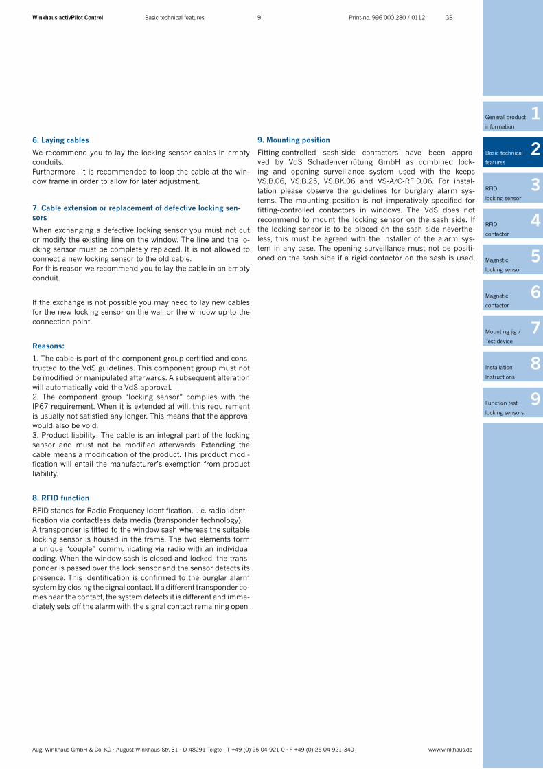
6. Laying cables
We recommend you to lay the locking sensor cables in empty conduits. Furthermore it is recommended to loop the cable at the win-dow frame in order to allow for later adjustment.
7. Cable extension or replacement of defective locking sen-sors
When exchanging a defective locking sensor you must not cut or modify the existing line on the window. The line and the lo-cking sensor must be completely replaced. It is not allowed to connect a new locking sensor to the old cable. For this reason we recommend you to lay the cable in an empty conduit.
If the exchange is not possible you may need to lay new cables for the new locking sensor on the wall or the window up to the connection point.
Reasons:
1. The cable is part of the component group certified and cons-tructed to the VdS guidelines. This component group must not be modified or manipulated afterwards. A subsequent alteration will automatically void the VdS approval.2. The component group “locking sensor” complies with the IP67 requirement. When it is extended at will, this requirement is usually not satisfied any longer. This means that the approval would also be void. 3. Product liability: The cable is an integral part of the locking sensor and must not be modified afterwards. Extending the cable means a modification of the product. This product modi-fication will entail the manufacturer’s exemption from product liability.
8. RFID function
RFID stands for Radio Frequency Identification, i. e. radio identi-fication via contactless data media (transponder technology).A transponder is fitted to the window sash whereas the suitable locking sensor is housed in the frame. The two elements form a unique “couple” communicating via radio with an individual coding. When the window sash is closed and locked, the trans-ponder is passed over the lock sensor and the sensor detects its presence. This identification is confirmed to the burglar alarm system by closing the signal contact. If a different transponder co-mes near the contact, the system detects it is different and imme-diately sets off the alarm with the signal contact remaining open.
9. Mounting position
Fitting-controlled sash-side contactors have been appro-ved by VdS Schadenverhütung GmbH as combined lock-ing and opening surveillance system used with the keeps VS.B.06, VS.B.25, VS.BK.06 and VS-A/C-RFID.06. For instal-lation please observe the guidelines for burglary alarm sys-tems. The mounting position is not imperatively specified for fitting-controlled contactors in windows. The VdS does not recommend to mount the locking sensor on the sash side. If the locking sensor is to be placed on the sash side neverthe-less, this must be agreed with the installer of the alarm sys-tem in any case. The opening surveillance must not be positi-oned on the sash side if a rigid contactor on the sash is used.
Basic technical featuresWinkhaus activPilot Control 9 Print-no. 996 000 280 / 0112 GB
2
3
4
5
6
7
8
9
1
Mounting jig /
Test device
Function test
locking sensors
General product
information
Magnetic
contactor
Basic technical
features
RFID
locking sensor
RFID
contactor
Magnetic
locking sensor
Installation
Instructions
Aug. Winkhaus GmbH & Co. KG · August-Winkhaus-Str. 31 · D-48291 Telgte · T +49 (0) 25 04-921-0 · F +49 (0) 25 04-921-340 www.winkhaus.de
2Basic technical
features

Product description alarm keep
General
As yet reed contacts for window surveillance have primarily been installed visibly on the window sash and frame. Winkhaus activPi-lot locking sensors for alarm and surveillance systems are inte-grated into the window fitting and thus they cannot immediately be perceived.
Application area
The activPilot Control product range is suitable for electronic moni-toring of windows and doors. According to VdS, the locking sensors are intended for use as intrusion detectors without system depen-dency. Model VS-A/C-RFID is not system free.
Contact keeps VS-A/C-RFID.06
- Combined opening and locking surveillance in burglary alarm systems of class C, VdS no. G 108093
Contact keeps VS.B.06 and VS.B.25
- Combined opening and locking surveillance in burglary alarm systems (EMA) of class B, VdS no. G 106511
Contact keeps VS.BK.06
- Combined opening and locking surveillance in burglary alarm systems of class B, VdS no. G 110505
- With additional status enquiry “tilt” (K) when used horizontally at the bottom.
System advantages
- Can be easily integrated into the standard Winkhaus activPilot turn-tilt fitting.
- Integration into other fitting systems is possible (on request)- Adjustable via elongated holes- The locking sensors are suitable for conventional window designs.
Alarm locking sensors
Overview of system components
For the status enquiry of the window a switch contact is needed as follows: frame-side contact keep and sash-side contactor.
Winkhaus activPilot Control
2
3
4
5
6
7
8
9
1
10 Print-no. 996 000 280 / 0112 GB
3
Aug. Winkhaus GmbH & Co. KG · August-Winkhaus-Str. 31 · D-48291 Telgte · T +49 (0) 25 04-921-0 · F +49 (0) 25 04-921-340 www.winkhaus.de

Locking sensor VS-A/C-RFID.06
(VdS class C)- RFID locking sensor VS-A/C-RFID.06 for combined opening
and locking control
- VdS-approved locking sensor with locking contact and sabo-
tage loop for alarm and monitoring systems VdS no.
G 108093, environmental class III
- Integrated LED to indicate triggered alarm signals
- Scope of delivery: 1 contact keep, 3 adapters and 2 fixing
screws
- Utilisation in combination with one of the RFID contactors
E1.VS-RFID, MK.VS-RFID.250-1 or VS-RFID-G-05.5/4
Technical data
AL
- Nominal supply voltage: 12 V ± 3 V
- Current consumption with 12 V: ≤10 mA
- Activate the input signal (12 V DC)
- Alarm contact (potential free)
- Switch voltage: max. 48 V DC
- Switching current: max. 50 mA
- Contact resistance: 25 Ω
- Temperature range: -25 °C to +55 °C
- Protection class: IP67 according to DIN EN 60529
- External dimensions: length 104 mm,
width 18 mm,
height 8.5 mm
Connection type for VS-A/C-RFID.06- 6 m connecting cable integrally cast, white, 7 x 0.14mm²,
diameter 4.3 mm
rtsw
gn ws
LED
0V
+12V DC
ws
gnrtsw
C
I : Contactor (transponder)
II: Locking sensor (receiver unit)
Wiring assignment
ws = white – signal contact + sabotage loop
gn = green – activation (+12V DC)
rt = red – supply voltage (+12V DC)
sw = black – earth (0V)
Article description Article No. Cable length VdS approval VPA1Qty. Type
VPA2Qty. Type
VPA3Qty. Type
VS-A/C-RFID.06 4983720 2 6 m C 1 BL 20 KK 480 EK
RFID contactorWinkhaus activPilot Control 11 Print-no. 996 000 280 / 0112 GB
2
3
4
5
6
7
8
9
1
Mounting jig /
Test device
Function test
locking sensors
General product
information
Magnetic
contactor
Basic technical
features
RFID
locking sensor
RFID
contactor
Magnetic
locking sensor
Installation
Instructions
Aug. Winkhaus GmbH & Co. KG · August-Winkhaus-Str. 31 · D-48291 Telgte · T +49 (0) 25 04-921-0 · F +49 (0) 25 04-921-340 www.winkhaus.de
3RFID
locking sensor

Corner drive
E1.VS-RFID
- Corner drive with RFID contactor
- RFID contactor for RFID locking sensor VS-A/C-RFID.06
- Safety locking pin as a manually adjustable octagonal bolt
- Central fastening as standard
- Automatic and manual assembly possible
AL
Article description Article No. VPA1Qty. Type
VPA2Qty. Type
E1.VS-RFID 4936079 4 100 KK 800 EK
RFID contactorWinkhaus activPilot Control
2
3
4
5
6
7
8
9
1
12 Print-no. 996 000 280 / 0112 GB
4
Aug. Winkhaus GmbH & Co. KG · August-Winkhaus-Str. 31 · D-48291 Telgte · T +49 (0) 25 04-921-0 · F +49 (0) 25 04-921-340 www.winkhaus.de
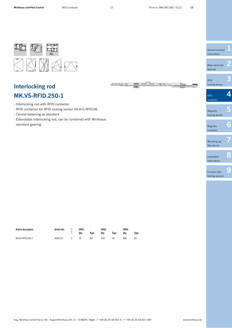
Interlocking rod
MK.VS-RFID.250-1- Interlocking rod with RFID contactor
- RFID contactor for RFID locking sensor VS-A/C-RFID.06
- Central fastening as standard
- Extendable interlocking rod, can be combined with Winkhaus
standard gearing
AL
Article description Article No. VPA1Qty. Type
VPA2Qty. Type
VPA3Qty. Type
MK.VS-RFID.250-1 4936131 2 20 BD 100 KK 800 EK
RFID contactorWinkhaus activPilot Control 13 Print-no. 996 000 280 / 0112 GB
2
3
4
5
6
7
8
9
1
Mounting jig /
Test device
Function test
locking sensors
General product
information
Magnetic
contactor
Basic technical
features
RFID
locking sensor
RFID
contactor
Magnetic
locking sensor
Installation
Instructions
Aug. Winkhaus GmbH & Co. KG · August-Winkhaus-Str. 31 · D-48291 Telgte · T +49 (0) 25 04-921-0 · F +49 (0) 25 04-921-340 www.winkhaus.de
4RFID
contactor

Contactors
VS-RFID-G ...- RFID contactor for RFID locking sensor VS-A/C-RFID.06
- Fitting-independent RFID contactor for drive rod fittings
- For airgaps of 10 to 15 mm
AL
M5
Article description Article No. Bolt height Thread length Airgap from / to VPA1Qty. Type
VPA2Qty. Type
VPA3Qty. Type
VS-RFID-G-05,5/4 4936134 5,5 4 10 - 15 20 BL 200 KK 1600 EK
RFID contactorWinkhaus activPilot Control
2
3
4
5
6
7
8
9
1
14 Print-no. 996 000 280 / 0112 GB
4
Aug. Winkhaus GmbH & Co. KG · August-Winkhaus-Str. 31 · D-48291 Telgte · T +49 (0) 25 04-921-0 · F +49 (0) 25 04-921-340 www.winkhaus.de

Contact keeps VS.B.06 and VS.B.25
(VdS class B)
- VS.B.06 and VS.B.25 contact keeps for combined opening
and locking surveillance
- VdS-approved contact keep with locking contact for alarm
and monitoring systems VdS no. G 106511, environmental
class III
- Scope of delivery: 1 contact keep, 3 adapters and 2 fixing
screws
- Utilisation in combination with one of the magnetic contac-
tors E1.VS.KG, MK.VS.150.KG or MK.VS.250.KG
Technical data
AL
- Switch voltage: max. 48 V DC
- Switching current: max. 0.5 A
- Transport current: max. 1.0 A
- Contact resistance: max. 150 m Ω
- Switch performance: max. 10 W pure ohmic load
- Temperature range: -20° C to +70° C
- Protection class: IP67 according to DIN EN 60529
- Service life: min 107 switch cycles
- External dimensions: length 104 mm,
width 18 mm,
height 8.5 mm
Connection type for VS.B.06- 6 m connecting cable integrally cast, white, 4 x 0.14mm²,
diameter 3.5 mm
Connection type for VS.B.25- max. 25 m connecting cable integrally cast, white,
4 x 0.22 mm², diameter 3.5 mm
(B)
For safety reasons all wires are white
Article description Article No. Cable length VdS approval VPA1Qty. Type
VPA2Qty. Type
VPA3Qty. Type
VS.B.06 4983721 6 m B 1 BL 30 KK 720 EKVS.B.25 4983722 25 m B 1 BL 10 KK 240 EK
Magnetic locking sensorWinkhaus activPilot Control 15 Print-no. 996 000 280 / 0112 GB
2
3
4
5
6
7
8
9
1
Mounting jig /
Test device
Function test
locking sensors
General product
information
Magnetic
contactor
Basic technical
features
RFID
locking sensor
RFID
contactor
Magnetic
locking sensor
Installation
Instructions
Aug. Winkhaus GmbH & Co. KG · August-Winkhaus-Str. 31 · D-48291 Telgte · T +49 (0) 25 04-921-0 · F +49 (0) 25 04-921-340 www.winkhaus.de
5Magnetic
locking sensor

Contact keep VS.BK.06
(VdS class B)- Contact keep VS.BK.06 for combined opening and locking
surveillance
- VdS-approved contact keep with closing contact (B) and
sabotage loop for alarm and surveillance systems, VdS no.
G 110505, environmental class III
- With additional status enquiry “tilt” (K) when used horizon-
tally at the bottom.
- Scope of delivery: 1 contact keep, 3 adapters and 2 fixing
screws
- Utilisation in combination with one of the magnetic contac-
tors E1.VS.KG, MK.VS.150.KG or MK.VS.250.KG
- Note: Switching the fitting from the closed position to the tilt
position is impossible without iterrupting the contacts. The
tilt surveillance is not VdS approved.
Technical data
AL
- Switch voltage: max. 48 V DC
- Contact resistance: max. 150 m Ω
- Temperature range: -20° C to +70° C
- Protection class: IP67 according to DIN EN 60529
- Service life: min 107 switch cycles
- External dimensions: length 104 mm,
width 18 mm,
height 8.5 mm
Technical data surveillance (B)- Switching current: max. 0.5 A
- Transport current: max. 1.0 A
- Switch performance: max. 10 W pure ohmic load
Technical data status enquiry “tilt” (K)- Switching current: max. 0.25 A
- Transport current: max. 1.2 A
- Switch performance: max. 3 W pure ohmic load
Connection type for VS.BK.06- 6 m connecting cable integrally cast, white, 7 x 0.14mm²,
diameter 4.3 mm
3 br2 sw
1 bl ws
(B)
(K)
ws
1 bl
2 sw3 br
Wiring assignment
ws = white (signal contact + sabotage loop)
bl = blue
sw = black
br = brown
For safety reasons all wires of the four surveillance cables are white. The wire ends
are marked in order to distinguish them.
Article description Article No. Cable length VdS approval VPA1Qty. Type
VPA2Qty. Type
VPA3Qty. Type
VS.BK.06 4983723 6 m B 1 BL 20 KK 480 EK
Magnetic locking sensorWinkhaus activPilot Control
2
3
4
5
6
7
8
9
1
16 Print-no. 996 000 280 / 0112 GB
5
Aug. Winkhaus GmbH & Co. KG · August-Winkhaus-Str. 31 · D-48291 Telgte · T +49 (0) 25 04-921-0 · F +49 (0) 25 04-921-340 www.winkhaus.de

Product description climate keep
General
Switch unit, e. g. for avoiding loss of energy when the window is open while the heating is on.To this effect a switch contact integrated into the fitting is used. In combination with suitable radiator thermostat valves or control units this contact allows the radiator activity to be reduced when a window or patio door is opened.The suitable radiator thermostat valves, radiator control units and radiator power supply units can be obtained from specialist dea-lers of sanitary equipment.
Application area
- Heating and climate control according to the motto “Open window – switch off heating”
- For controlling ventilating systems- For simple state enquiry- Query option of position “open” or “closed”
Note: For controlling ventilation systems using the VS.K climate keep we recommend you to apply a rigid con-tactor. So you can be sure that the system can only be activated when the window is in the tilt position.
System advantages
- Can be easily integrated into the standard Winkhaus activPilot turn-tilt fitting.
- Integration into other fitting systems is possible (on request)- Adjustable via elongated holes- The locking sensors are suitable for conventional window designs.
Magnetic locking sensorWinkhaus activPilot Control 17 Print-no. 996 000 280 / 0112 GB
2
3
4
5
6
7
8
9
1
Mounting jig /
Test device
Function test
locking sensors
General product
information
Magnetic
contactor
Basic technical
features
RFID
locking sensor
RFID
contactor
Magnetic
locking sensor
Installation
Instructions
Aug. Winkhaus GmbH & Co. KG · August-Winkhaus-Str. 31 · D-48291 Telgte · T +49 (0) 25 04-921-0 · F +49 (0) 25 04-921-340 www.winkhaus.de
5Magnetic
locking sensor

Contact keep VS.K.06- Contact keep VS.K06 for climate control, e. g. energy-efficient
window ventilation or control of ventilating systems
- Contact keep with changeover contact (K) for energy-efficient
window ventilation
- For the status enquiry of the window a switch contact is nee-
ded as follows: frame-side contact keep with integrated reed
contact and sash-side fitting-independent magnetic contactor
- Scope of delivery: 1 contact keep, 3 adapters and 2 fixing
screws
- Used in combination with one of the magnetic contactors
E1.VS.KG, MK.VS.150.KG, MK.VS.250.KG, VS.KG... or VS.KGS...
Technical data
AL
- Switch voltage: max. 48 V DC
- Switching current: max. 0.25 A
- Transport current: max. 1.2 A
- Contact resistance: max. 150 m Ω
- Switch performance: max. 3 W pure ohmic load
- Temperature range: -20° C to +70° C
- Protection class: IP67 according to DIN EN 60529
- Service life: min 107 switch cycles
- External dimensions: length 104 mm,
width 18 mm,
height 8.5 mm
Connection type for VS.K.06- 6 m connecting cable integrally cast, black, 3 x 0.14mm²,
diameter 3.5 mm
(K)
Wire colours:
1 = blue
2 = black
3 = brown
Article description Article No. Cable length VdS approval VPA1Qty. Type
VPA2Qty. Type
VPA3Qty. Type
Contact keep VS.K.06 4983724 6 m - 1 BL 30 KK 720 EK
Magnetic locking sensorWinkhaus activPilot Control
2
3
4
5
6
7
8
9
1
18 Print-no. 996 000 280 / 0112 GB
5
Aug. Winkhaus GmbH & Co. KG · August-Winkhaus-Str. 31 · D-48291 Telgte · T +49 (0) 25 04-921-0 · F +49 (0) 25 04-921-340 www.winkhaus.de

Corner drive
E1.VS.KG- Corner drive with magnetic contactor
- Magnetic contactor for magnetic locking sensors VS.B...,
VS.BK.06 or VS.K.06
- Safety locking pin as a manually adjustable octagonal bolt
- Central fastening as standard
- Automatic and manual assembly possible
AL
Article description Article No. VPA1Qty. Type
VPA2Qty. Type
VPA3
E1.VS.KG 4966405 100 KK 800 EK
Magnetic contactorWinkhaus activPilot Control 19 Print-no. 996 000 280 / 0112 GB
2
3
4
5
6
7
8
9
1
Mounting jig /
Test device
Function test
locking sensors
General product
information
Magnetic
contactor
Basic technical
features
RFID
locking sensor
RFID
contactor
Magnetic
locking sensor
Installation
Instructions
Aug. Winkhaus GmbH & Co. KG · August-Winkhaus-Str. 31 · D-48291 Telgte · T +49 (0) 25 04-921-0 · F +49 (0) 25 04-921-340 www.winkhaus.de
6Magnetic
contactor

Interlocking rod
MK.VS.250.KG- Interlocking rod with magnetic contactor
- Magnetic contactor for magnetic locking sensors VS.B...,
VS.BK.06 or VS.K.06
- Central fastening as standard
- Extendable interlocking rod, can be combined with Winkhaus
standard gearing
- Face plate length 250 mm
Interlocking rod MK.VS.150.KG
AL
Article description Article No. VPA1Qty. Type
VPA2Qty. Type
VPA3Qty. Type
MK.VS.250.KG 4966406 20 BD 100 KK 800 EK
Magnetic contactor
- Designed as described above, but with face plate length
150 mm
Winkhaus activPilot Control
2
3
4
5
6
7
8
9
1
20 Print-no. 996 000 280 / 0112 GB
6
Aug. Winkhaus GmbH & Co. KG · August-Winkhaus-Str. 31 · D-48291 Telgte · T +49 (0) 25 04-921-0 · F +49 (0) 25 04-921-340 www.winkhaus.de

Other contactors- Magnetic contactor for magnetic locking sensor VS.K...
Contactor VS-KGS.04
AL
- Magnetic contactor 14 mm wide
- Reduced installation height (4 mm); it enables installation for
12 mm airgap
- Mounted on the fitting’s face plate
- Construction size 4 mm
Contactor VS.KGS.06- Magnetic contactor 16 mm wide
- Mounted into the fitting groove
- Construction size 6 mm
Contactor VS.KGS.04- Fitted to the face plate by means of a countersunk screw M5
x 6 mm, DIN ISO 7046 (not included in the scope of delivery)
- Construction size 4 mm
Contactor VS.KG.06-4- Fitting-independent magnetic contactor for drive-rod fittings.
- Bolt height 6 mm
- Thread length 4 mm
6 mm
4 mm
M5
Article description Article No. Airgap from / to VPA1Qty. Type
VPA2Qty. Type
VPA3Qty. Type
VS.KGS.04 4966407 10 - 15 10 BL 500 KK 12000 EKVS.KGS.06 4966408 10 - 15 10 BL 500 KK 12000 EKVS.KG.04 4977756 10 - 15 10 BL 500 KK 12000 EKVS.KG.06-4 4966410 12 - 17 10 BL 500 KK 12000 EK
Magnetic contactorWinkhaus activPilot Control 21 Print-no. 996 000 280 / 0112 GB
2
3
4
5
6
7
8
9
1
Mounting jig /
Test device
Function test
locking sensors
General product
information
Magnetic
contactor
Basic technical
features
RFID
locking sensor
RFID
contactor
Magnetic
locking sensor
Installation
Instructions
Aug. Winkhaus GmbH & Co. KG · August-Winkhaus-Str. 31 · D-48291 Telgte · T +49 (0) 25 04-921-0 · F +49 (0) 25 04-921-340 www.winkhaus.de
6Magnetic
contactor

Drilling jig locking sensor- Drilling jig for Winkhaus locking sensors VS-A/C-RFID.06,
VS.B.06, VS.B.25 and VS.BK.06
AL
Article description Article No.LEHRE VS A/C RFID 4937653
Mounting jig / Test deviceWinkhaus activPilot Control
2
3
4
5
6
7
8
9
1
22 Print-no. 996 000 280 / 0112 GB
7
Aug. Winkhaus GmbH & Co. KG · August-Winkhaus-Str. 31 · D-48291 Telgte · T +49 (0) 25 04-921-0 · F +49 (0) 25 04-921-340 www.winkhaus.de
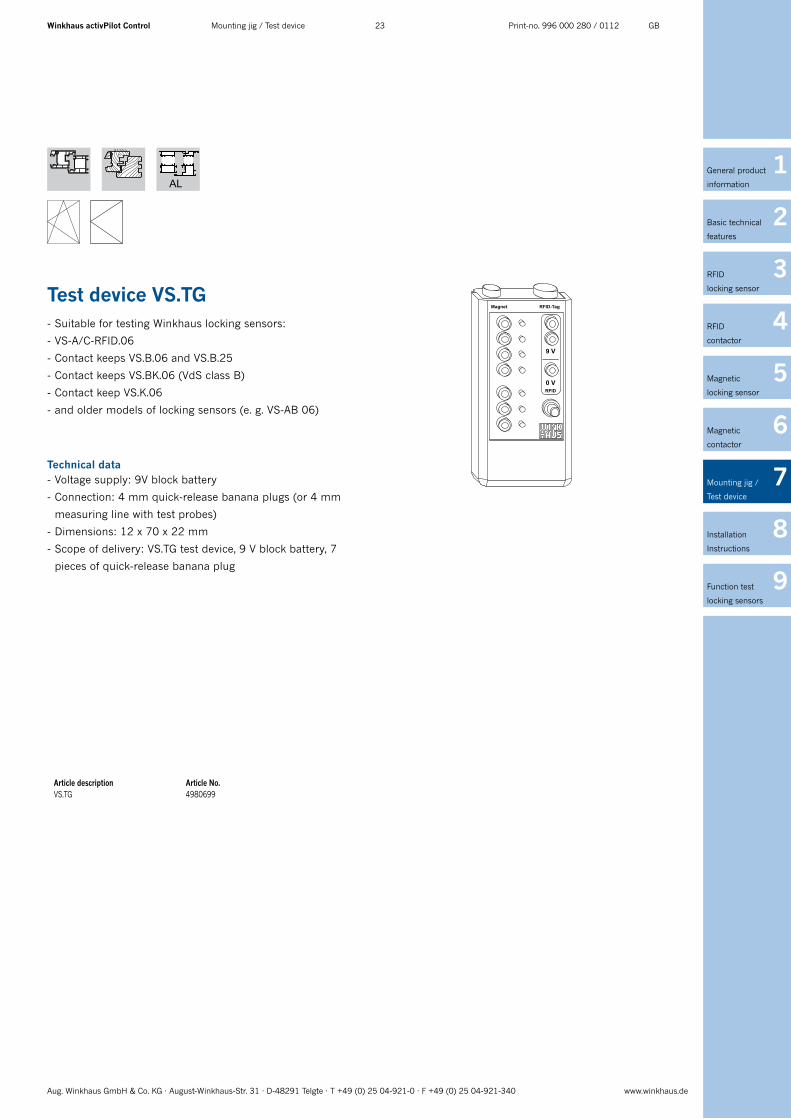
Test device VS.TG- Suitable for testing Winkhaus locking sensors:
- VS-A/C-RFID.06
- Contact keeps VS.B.06 and VS.B.25
- Contact keeps VS.BK.06 (VdS class B)
- Contact keep VS.K.06
- and older models of locking sensors (e. g. VS-AB 06)
Technical data
AL
- Voltage supply: 9V block battery
- Connection: 4 mm quick-release banana plugs (or 4 mm
measuring line with test probes)
- Dimensions: 12 x 70 x 22 mm
- Scope of delivery: VS.TG test device, 9 V block battery, 7
pieces of quick-release banana plug
Article description Article No.VS.TG 4980699
Mounting jig / Test deviceWinkhaus activPilot Control 23 Print-no. 996 000 280 / 0112 GB
2
3
4
5
6
7
8
9
1
Mounting jig /
Test device
Function test
locking sensors
General product
information
Magnetic
contactor
Basic technical
features
RFID
locking sensor
RFID
contactor
Magnetic
locking sensor
Installation
Instructions
Aug. Winkhaus GmbH & Co. KG · August-Winkhaus-Str. 31 · D-48291 Telgte · T +49 (0) 25 04-921-0 · F +49 (0) 25 04-921-340 www.winkhaus.de
7Mounting jig /
Test device

Installation Instructions
Introduction
These mounting instructions specify the installation and the electrical connection of the Winkhaus locking sensors to a win-dow or patio door.Any person involved in mounting fittings must have read and understood this fitting guide. Particularly the following section “Safety Instructions” must be observed.After installation of the locking sensors these mounting instruc-tions should be kept at the window for the electrician to find it or it should be submitted directly to the electrician.
Safety instructions / Installation conditions
In order to guarantee the proper function of locking sen-sors, mounting must be carried out in accordance with the manufacturer’s instructions. Installation may only be performed by skilled and safety-conscious staff.Generally it is important to observe the stipulations of VdS Schadenverhütung GmbH (VdS guidelines) regarding burglary alarm systems. Furthermore please make sure that the electrical connection and performance data of the individual components are com-patible and that they are adhered to even while the system is used.
Please verify the following details:- Is the burglary alarm system in line with valid stipulations and classifications (A, B, C to VdS)?- Are there precise mounting and installation instructions for the burglary alarm system?- Are the conductor cross sections of the connection cables com-patible and can the connection be implemented in accordance with the installation instructions?
Special instructions
The locking sensor must not be used in steel windows, because magnetic interference fields might affect its function. Please make sure that only the supplied fixing screws are used.
Scope of supply
The package contents is always restricted to one type of locking sensors as well as fixing screws and adapters FT1, FT4 and FT5.
Intended use
Sash-side contactors in combination with keeps VS.B. ..., VS.BK.06 and VS-A/C-RFID.06:The locking sensor is exclusively intended for the surveillance of windows and patio doors in burglary alarm systems. This locking sensor has been approved by VdS Schaden-verhütung GmbH (damage prevention). For installation please observe the guidelines for burglary alarm systems. In the VdS guideline for burglary alarm systems VdS 2311:1998-12, article 10.1.1 ABC choice of detectors, it reads:“The choice and use of detectors must be made with the aim to ensure a safe detection and operation without giving false alarms while considering the monitoring role, ambient condi-tions and the installation instructions of the system supplier / manufacturer.”
Winkhaus locking sensors and contactors are exclusively inten-ded for the use described above. Any other utilisation is impro-per utilisation. We do not assume any liability in case of impro-per installation or mounting and if third-party or non-approved system components are used! Moreover, the VdS approval is void in this case.
Sash-side contactor in combination with locking sensor VS.K.06:The locking sensor signal is intended for controlled ventilation.As an example, this may include the control of power supply units switching off the heating when the window is open.
Installation positions
Fitting-controlled sash-side contactors have been appro-ved by VdS Schadenverhütung GmbH as combined lock-ing and opening surveillance system used with the keeps VS.B.06, VS.B.25, VS.BK.06 and VS-A/C-RFID.06. For instal-lation please observe the guidelines for burglary alarm sys-tems. The mounting position is not imperatively specified for fitting-controlled contactors in windows. The VdS does not recommend to mount the locking sensor on the sash side. If the locking sensor is to be placed on the sash side neverthe-less, this must be agreed with the installer of the alarm sys-tem in any case. The opening surveillance must not be positi-oned on the sash side if a rigid contactor on the sash is used.
Installation InstructionsWinkhaus activPilot Control
2
3
4
5
6
7
8
9
1
24 Print-no. 996 000 280 / 0112 GB
8
Aug. Winkhaus GmbH & Co. KG · August-Winkhaus-Str. 31 · D-48291 Telgte · T +49 (0) 25 04-921-0 · F +49 (0) 25 04-921-340 www.winkhaus.de

Assembly of contactors
Magnetic / RFID contactors
Installation positions
See figure: Winkhaus activPilot fittings with contactors
The process to follow when mounting the sash-side contactors is the same as for standard activPilot fitting parts.
Important: The sash-side signal contact must not be used as a locking point. The function of the fitting must not be obstructed by the signal contact. With regard to burglar-proof windows, the sash-side signal contact must by no means replace a security locking point, but must be installed separately. During installation works it is important to heed the locking positions of the locking bolts.
1 2
Winkhaus activPilot fittings with contactors
1. Magnetic contactor
2. RFID contactor
Mounting the interlocking rod with contactor
If your window or patio door is equipped with a Winkhaus fit-ting offering the suitable dimensions, you can use the interlo-cking rods MK.VS.150.KG, MK.VS.250.KG or MK.VS-RFID.250-1.
In case of sufficient space you can fix the interlocking rod to vari-ous locations on the window or the patio door: - between the top rod and the corner drive- on the drive rod- on the corner drive
As a circumferential, concealed window fitting is concerned here, the VdS does not stipulate a definite position of locking surveil-lance.
Note: All locking sensors and contactors are sensitive to impact. Please absolutely avoid vibrations and shocks. After receipt please check all components for transport damages. In order to ensure the exact positioning of the locking sensors, we recommend to complete the installation of the sash-side contactors beforehand. The installation position of the locking sensor depends on the chosen position of the sash-side contactor. The lock-ing sensor must be installed in a way to protect the locking sensor and the cables from manipulation from the outside.
Installation InstructionsWinkhaus activPilot Control 25 Print-no. 996 000 280 / 0112 GB
2
3
4
5
6
7
8
9
1
Mounting jig /
Test device
Function test
locking sensors
General product
information
Magnetic
contactor
Basic technical
features
RFID
locking sensor
RFID
contactor
Magnetic
locking sensor
Installation
Instructions
Aug. Winkhaus GmbH & Co. KG · August-Winkhaus-Str. 31 · D-48291 Telgte · T +49 (0) 25 04-921-0 · F +49 (0) 25 04-921-340 www.winkhaus.de
8Installation
Instructions

Installation of the locking sensor on
the frame
(Magnet / RFID technology)
- Drill clearance hole ø 9 mm for the cable (2).- If necessary, pre-drill the fixing points.- If required, fix the adapter to the locking sensor (1).
Attention! When mounting the locking sensor, please make sure that the cable is not damaged.
1
3
2
4
1
2
XX
mm
Ø 9 mm
YY
mm
5
Mounting diagram locking sensor ( with E1.VS ...)
XX = 37 mm ; YY = 120 mm
Important: Loop the cable to allow for later adjustment of the locking sensor (see 5)!
Note: The overview on the following page shows the sui-table adapters for the individual frame profiles. (When using an adapter, please remove the bar (3) in order to allow for the cable to be easily laid.) Clip the adapter (4) to the locking sensor (1).
Note: For airgaps exceeding 16.5 – 20.5 mm please use a profile-independent adapter FT.RFID.N.4 for the locking sensor.
- Lead the cable through the ø 9 mm hole.- Fix the locking sensor.- Loop the cable (2) at the exit of the ø 9 mm drilling and lay the cable along the frame.
Note: When installing the locking sensor, please make sure that the window is already locked when the sen-sor conveys the locking signal. This means, the locking bolts must have entered the keeps 50 %.
Ø 9
mm
A
Ø 7
-9 m
m
A
Cross section timber and PVC-U profile incl. drill position
Dimension: A = 6 mm
Installation position of locking sensors if an E1.VS... corner drive is used
Note: The dimensions refer to the turn position and are applicable to Winkhaus fittings with an 18.5 mm / 37 mm stroke.
Installation InstructionsWinkhaus activPilot Control
2
3
4
5
6
7
8
9
1
26 Print-no. 996 000 280 / 0112 GB
8
Aug. Winkhaus GmbH & Co. KG · August-Winkhaus-Str. 31 · D-48291 Telgte · T +49 (0) 25 04-921-0 · F +49 (0) 25 04-921-340 www.winkhaus.de

Electrical connection
Connect the locking sensor according to the wiring diagram on the product page.
Opening and locking surveillance (magnetic contacts)
Suitable for use are the keeps VS.B.../VS.BK.06 (burglar alarm sys-tem) and VS.K.06 (climate control). Actuation of the contact is per-formed when the fitting is unlocked in the turn or tilt position
Note: The tilt control device is not VdS approved.
Tilt surveillance
Suitable for use are the keeps VS.B... and VS.K.06 (clim-ate control). The contact is only actuated in the tilt positi-on. For tilt surveillance the installation position must be at the bottom of the window. It is important to observe the in-stallation and tolerance values also in the tilt position.
Note: Switching the fitting from the closed position to the tilt position is impossible without interrupting the contacts. The tilt surveillance is not VdS approved.
Status enquiry
The fixed sash-side contactors VS.KG... and VS.KGS... are only used to make a state enquiry (to check whether the sash is in the frame). To this effect the keep VS.K.06 (climate control) can be used. The contact is actuated as soon as the window sash is moved into the turn or tilt position.
Note: Monitoring by means of a fixed contactor for combined opening and locking surveillance is not VdS approved.
Note: The locking sensor is suitable for groove positions of 9 to 13 mm and airgaps of 10 to 15 mm.
Installation InstructionsWinkhaus activPilot Control 27 Print-no. 996 000 280 / 0112 GB
2
3
4
5
6
7
8
9
1
Mounting jig /
Test device
Function test
locking sensors
General product
information
Magnetic
contactor
Basic technical
features
RFID
locking sensor
RFID
contactor
Magnetic
locking sensor
Installation
Instructions
Aug. Winkhaus GmbH & Co. KG · August-Winkhaus-Str. 31 · D-48291 Telgte · T +49 (0) 25 04-921-0 · F +49 (0) 25 04-921-340 www.winkhaus.de
8Installation
Instructions

Position of the contactor
Positions of the magnetic contactorI: TiltII: TurnIII: Lock
Components:1 Corner drive2 Contactor3 Locking sensor4 Receiver unit5 Tilt sensor for VS.BK.06
Dimensions (for 9/13 mm groove position):W: 61.5 mmX: 0 to max. 5 mmY: 34 mmZ: 49 mm (cable drilling position Ø 9mm)a: Airgap
Installation Instructions
Y
1
24
3
1
Z
5(VS.BK.06)
W
Winkhaus activPilot Control
2
3
4
5
6
7
8
9
1
28 Print-no. 996 000 280 / 0112 GB
8
Aug. Winkhaus GmbH & Co. KG · August-Winkhaus-Str. 31 · D-48291 Telgte · T +49 (0) 25 04-921-0 · F +49 (0) 25 04-921-340 www.winkhaus.de

Opening and locking surveillance (RFID contact)
The RFID system is based on the contactless data transfer between the window frame and the sash. The transponder is fitted to the window sash whereas the suitable locking sensor is housed in the frame.The transponder is integrated into the contactor and indicates the state of the window sash while a reader device is housed in the locking sensor. By means of electromagnetic waves the reader de-vice can detect the transponder and in this way it identifies the state of the contactor.The two elements <transponder> and <reader device> feature an individual coding and form a unique “couple”.
Status enquiry
When the window sash is closed and locked, the transponder is passed over the locking sensor and the reader device detects its presence. In this position the burglary alarm system is informed about the states “closed” and “locked”.
Note: The locking sensor is suitable for groove positions of 9 and 13 mm and an airgap of 10 to 15 (19) mm. If the airgap exceeds 15 mm, it is important to use an adapter FT.RFID.N.4 for the locking sensor.
Positions of RFID contactor
Positions of RFID contactorI: TiltII: TurnIII: Lock
Components:1 Corner drive2 Contactor (transponder)3 Locking sensor4 Receiver unit
Dimensions:W: 61.5 mmX: 0 to max. 5 mmY: 34 mmZ: 49 mm (cable drilling position Ø 9mm)a: Airgap
Installation Instructions
Y
1
24
3
1
ZW
Winkhaus activPilot Control 29 Print-no. 996 000 280 / 0112 GB
2
3
4
5
6
7
8
9
1
Mounting jig /
Test device
Function test
locking sensors
General product
information
Magnetic
contactor
Basic technical
features
RFID
locking sensor
RFID
contactor
Magnetic
locking sensor
Installation
Instructions
Aug. Winkhaus GmbH & Co. KG · August-Winkhaus-Str. 31 · D-48291 Telgte · T +49 (0) 25 04-921-0 · F +49 (0) 25 04-921-340 www.winkhaus.de
8Installation
Instructions

Adapters locking sensors
Profile-specific adapters (included in the scope of delivery):
FT1
Aluplast 2000 - 8000BrügmannDeceuninckDimexGealanInternova 6000KBEKBE (9 mm groove pos.)KömmerlingLB. ProfilePlustecRehauRoplasto 6002 / 7001SalamanderSchüco CT 60 / CT 70Trocal A5 / M5VEKAWymar 2500 / 3000
FT4
Trocal 2000 / 88+
FT 5
Inoutic
Profile-independent adapters (must be ordered separately)
FT.RFID.N.4(Installation height 4 mm)Art-Nr.: 4938913
Installation InstructionsWinkhaus activPilot Control
2
3
4
5
6
7
8
9
1
30 Print-no. 996 000 280 / 0112 GB
8
Aug. Winkhaus GmbH & Co. KG · August-Winkhaus-Str. 31 · D-48291 Telgte · T +49 (0) 25 04-921-0 · F +49 (0) 25 04-921-340 www.winkhaus.de

Function test with test device VS.TG
See figure: Test device VS.TG
The VS.TG test device is used to check the Winkhaus locking sen-sors VS-A/C-RFID.06, VS.B.06, VS.BK.06, VS.K.06 and older models of locking sensors, such as VS-A/B 06.1. Quadruple connector panel for connecting the four white connection lines of the locking sensors VS.B.06, VS.BK.06 and VS-A/C-RFID.06 etc. 2. Triple connector panel for connecting the connection lines (blue, black, brown) of the climate keeps VS.K.06 and VS.BK.06.3. Triple connector panel, offset, for connecting the voltage supply (± 9 V) and the arming (+9 V) of the RFID locking sensor VS-A/C-RFID.064. On/off switch5. Magnetic contactor6. RFID Contactor
- By squeezing the open strand of the locking sensors, it can be inserted into the quick-release banana plug.
Remark: For test purposes the contactors 5 and 6 can also be used in place of the existing contacts. Important: If you use the RFID contactor (6) for the test, disconnect the locking sensor from the voltage afterwards.
5 6
31
24
Test device VS.TG
Testing procedure opening and locking surveillance:
For testing the opening and locking surveillance the four whi-te strands must be connected to the test device (block of four, 1). Then switch on the device. In case of VS-A/C-RFID.06 sensors please additionally make sure that the voltage (3) is applied in line with the colours of wires. After the strands have been connected, the sabotage line is de-tected automatically and indicated by the lit LEDs. The order and arrangement of strands is selectable at will. When the signal line is closed (this means when the window is locked) the two remaining LEDs light up.
Note: The four white strands can be applied in any desi-red order.
Testing procedure climate keep:
For the climate keeps test (changeover contact) the three coloured strands (black, brown, blue) must be connected to the test device (block of three, see 2).After applying the strands the “normally open side” is detected and indicated by the lit LEDs. When the magnetic transmitter is connected to the keep the LEDs change over to the “normally closed side”.
Installation Instructions
Note: The coloured strands can be applied in any desi-red order.
Winkhaus activPilot Control 31 Print-no. 996 000 280 / 0112 GB
2
3
4
5
6
7
8
9
1
Mounting jig /
Test device
Function test
locking sensors
General product
information
Magnetic
contactor
Basic technical
features
RFID
locking sensor
RFID
contactor
Magnetic
locking sensor
Installation
Instructions
Aug. Winkhaus GmbH & Co. KG · August-Winkhaus-Str. 31 · D-48291 Telgte · T +49 (0) 25 04-921-0 · F +49 (0) 25 04-921-340 www.winkhaus.de
9Function test
locking sensors

Function test of magnetic locking
sensor with digital multimeter
- Connect two diagonally opposing strands to the test device.
Attention! Using a bulb continuity tester might damage the locking sensor. We recommend you to use standard digital multimeters incl. a continuity tester or our VS.TG test device.
Switch diagram Magnetic Locking Sensors
- Unlock and open the window.- If continuity is indicated, the two strands no. 2 are connected (sabotage line).
- If no continuity is indicated, the two strands no. 1 are connec-ted (signal line).
- Connect the strands no. 1 to the test device and close and lock the window.
- If the fitting magnet is mounted in the correct way, the test device shows continuity.
Important! If no continuity can be ascertained on a closed and locked window, please check the en-try depth of the magnet transmitter into the locking sensor. One possibility to determine the depth is to press modelling material into the locking sensor.
Important! The function test should be performed by the manufacturer after mounting and a second time at the installation site before the window is foam-insulated and installed.
Important: Loop the cable to allow for later adjustment of the locking sensor (see 5)!
Installation InstructionsWinkhaus activPilot Control
2
3
4
5
6
7
8
9
1
32 Print-no. 996 000 280 / 0112 GB
9
Aug. Winkhaus GmbH & Co. KG · August-Winkhaus-Str. 31 · D-48291 Telgte · T +49 (0) 25 04-921-0 · F +49 (0) 25 04-921-340 www.winkhaus.de

Function test of RFID locking sensors
with a digital multimeter
Identify and control signal contact
- Close the window; locking sensor is voltage free (no operating voltage).
- Identify the sabotage line from the 4 white lines by measuring (no continuity).
- The remaining 2 white lines (open) are the signal lines.- Apply operating voltage.- The signal contact must close now.- Arm the system (12V DC at signal input “scharf schalten”).- Open the window.- Cancel the activation- Alarm status LED must flash now.
Important! If no continuity can be ascertained on a closed and locked window, please check the entry depth of the RFID transmitter into the locking sensor. One pos-sibility to determine the depth is to press modelling ma-terial into the locking sensor.
0V
+12V DC
ws
gn
rt
sw
Identification of the sabotaged window
In the activated state a triggered alarm is stored by the locking sensor and it is indicated via LED after deactivation of the locking sensor. In case this function is not requested, the input of the arming must permanently be 12V.
Example: The window is locked, the locking sensor’s arming is activated. If, in this state, the window is opened for a short time (sabotaged), the alarm memory is set. After disarming the locking sensor, the alarm status LED is flashing. Thus the sabotaged win-dow can be identified afterwards.
Important! The function test should be performed by the manufacturer after mounting and a second time at the installation site before the window is foam-insulated and installed.
Installation Instructions
Wiring diagram RFID locking sensors
I : Contactor (transponder)
II: Locking sensor (receiver unit)
Wiring assignment
ws = white – signal contact + sabotage loop
gn = green – activation (+12V DC)
rt = red – supply voltage (+12V DC)
sw = black – earth (0V)
Winkhaus activPilot Control 33 Print-no. 996 000 280 / 0112 GB
2
3
4
5
6
7
8
9
1
Mounting jig /
Test device
Function test
locking sensors
General product
information
Magnetic
contactor
Basic technical
features
RFID
locking sensor
RFID
contactor
Magnetic
locking sensor
Installation
Instructions
Aug. Winkhaus GmbH & Co. KG · August-Winkhaus-Str. 31 · D-48291 Telgte · T +49 (0) 25 04-921-0 · F +49 (0) 25 04-921-340 www.winkhaus.de
9Function test
locking sensors

Notes


Aug. Winkhaus GmbH & Co. KG
August-Winkhaus-Straße 31
D-48291 Telgte
T +49 (0) 25 04-921-0
F +49 (0) 25 04-921-340
www.winkhaus.de
All
righ
ts, i
nclu
din
g th
e ri
ght
of a
lter
atio
n, a
re r
eser
ved
.9
96
00
0 2
80
GB
Pri
nt n
o.
FT T
R -
01
12