active power and reactive power regulation
DESCRIPTION
Active Power and Reactive Power RegulationTRANSCRIPT
1
Abstract--In this paper, taking the doubly fed induction
generator (DFIG) wind turbine as the research object, an electromagnetic transient simulation model is established in PSCAD/EMTDC simulation environment to analyze the active power and reactive power regulation capacity of DFIG wind turbine. Under different wind speed, maximum power point tracing (MPPT) control is implemented to ensure the optimum active power output, meanwhile the reactive power limits are calculated and combined with reactive power requirement of local load or the grid to determine the reactive power output. It can achieve operation optimization by making full use of a DFIG wind turbine capacity of the flexible power regulation.
Index Terms--Active Power; Control Strategy; DFIG; Decoupled Control; Dynamic Compensation; Maximum Power Point Tracking; Operation Optimization; Reactive Power Limits; the Stator Flux Field Oriented Control
I. INTRODUCTION OWADAYS, variable-speed constant-frequency (VSCF) wind-power doubly-fed induction generator is the most
widely used for wind farms with the development of wind power generation technology. Compared with constant speed constant frequency (CSCF) wind generating system, variable speed constant frequency doubly fed wind power generator presents noticeable advantages such as, it can keep the optimum tip-speed ratio to get maximum wind-power during a low wind speed and improve the flexibility of the drive system by releasing or saving some energy during high wind speed, in order to ensure the active power output smooth [1]-[6]. At the same time, doubly fed induction generator wind turbines can achieve the decoupled control of active and reactive powers. So it not only can work as a power supply to the grid, it can also be used as reactive power supply to stabilize the power system voltage around a prescribed value and deliver the
This work was supported in part by the North China Electric Power Research Institute.
Lei Sun is currently attending the Electrical Engineering Department , North China Electric Power University as a graduate student, Baoding, 071003 CHINA, (e-mail: [email protected]).
Zengqiang Mi is with the Department of Electrical Engineering, North China Electric Power University, Baoding, 071003 CHINA, (e-mail: [email protected]).
Yang Yu is with the Department of Electrical Engineering, North China Electric Power University, Baoding, 071003 CHINA, (e-mail: [email protected]).
Tao Wu is with North China Electric Power Research Institute, Beijing, 100045 CHINA, (e-mail: [email protected]).
Haifeng Tian is with the Department of Electrical Engineering, North China Electric Power University, Baoding, 071003 CHINA, (e-mail: [email protected]).
reactive power as compensation to local users near the wind farms. Therefore, calculation of the reactive power limits has important significance in selecting the reactive power control strategy and determining the set point of reactive power [7]-[10]. Hence, active power and reactive power regulation capacity study of DFIG wind turbine have attracted more attention.
In this paper, taking the doubly fed induction generator (DFIG) wind turbine as the research object, an electromagnetic transient simulation model is established in PSCAD/EMTDC simulation environment to analyze the active power and reactive power regulation capacity of DFIG wind turbine. By specifically analysing the decoupled control principle of active and reactive powers based on vector-oriented control method, the expressions and relationships of the active power, reactive power, current and voltage in the rotor and stator are studied, indicating the state of the DFIG under different wind speed. Finally, maximum power point tracing (MPPT) control is implemented to ensure the optimum active power output. The reactive power limits are calculated and combined with reactive power requirement of local load or the grid to determine the reactive power output. It can achieve operation optimization by making use of a DFIG wind turbine capacity of the flexible power regulation.
II. THE DECOUPLED CONTROL OF DFIG DFIG wind turbine includes a wound rotor induction
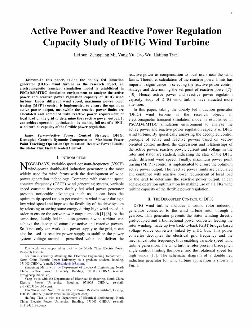
generator connected to the wind turbine rotor through a gearbox. This generator presents the stator winding directly grid-coupled and a bidirectional power converter feeding the rotor winding, made up two back-to-back IGBT bridges based voltage source converters linked by a DC bus. This power converter decouples the electrical grid frequency and the mechanical rotor frequency, thus enabling variable speed wind turbine generation. The wind turbine rotor presents blade pitch angle control limiting the power and the rotational speed for high winds [11]. The schematic diagram of a double fed induction generator for wind turbine application is shown in Fig. 1.
Active Power and Reactive Power Regulation Capacity Study of DFIG Wind Turbine
Lei sun, Zengqiang Mi, Yang Yu, Tao Wu, Haifeng Tian
N
2
Fig. 1. DFIG wind turbine
In this paper, the vector control strategy of the rotor side PWM converter is based on the stator field-orient vector control technology. The induction machine is controlled in a synchronous rotating dq axis frame, with the d-axis oriented along the stator-flux vector. In this way, Ψsd=Ψs, usq=us, Ψsq= usd=0, the relationship between the dq axis voltages, currents and active power, reactive power are calculated by [1], [12]:
( )
rdrd r rd r s r rq
rq mrq r rq r s s r rd
s
m ssd rd
s s
msq rq
s
diu r i L L i
dtdi L
u r i L L idt L
Li i
L LL
i iL
σ ω σ
σ ω ψ σ
ψ
⎧ = + ⋅ −⎪⎪⎪ = + ⋅ + +⎪⎪⎨⎪ = −⎪⎪⎪ =⎪⎩
(1)
2
1.5 1.5
1.5 1.5 1.5
ms sq sq s rq
s
m ss sq sd s rd
s n s
LP u i u i
L
L uQ u i u i
L Lω
⎧ = =⎪⎪⎨⎪ = = −⎪⎩
(2)
where u, r, i, Lσ, Ψ respectively represent the voltage, resistance, current, leakage inductance and flux; indexes d and q, the direct and quadrature components; indexes s and r refers to stator and rotor; ωr denotes rotor electrical speed,
21 m
s r
LL L
σ = −⋅
, s n rω ω ω= − .
The quadrature component of the rotor current irq is contributes to the machine active power, the direct component ird controls the reactive power entering the machine.
III. ACTIVE POWER REGULATION CAPACITY
A. Output Characteristics of Active Power The mechanical power P0 captured by a wind turbine,
depends on its tip-speed-ratio, λ, blade pitch angle, β, wind speed, Vw, and can be represented by [13]:
2 30 0.5 ( , )p wP C r Vβ λ ρπ= ⋅ (3)
with:
ρ: Air density R: Rotor radius Cp: Power coefficient as a function λ and β
For a particular wind turbine and a specified wind velocity, there is a value of λopt to ensure a maximum of Cpmax and a turbine rotational speed value that allows capturing the maximum mechanical power attainable from the wind.
Power relationship of DFIG can be obtained as
' '0
1 1
s e cu fe
m m r re
P P P P
P P P P PP
s s s
= − −⎧⎪⎨ − ±
= = =⎪ − −⎩
(4)
where Ps, Pcu, Pfe respectively represent the output power, copper losses, iron losses of the stator; Pe is the electric power of generator; Pm
’ is the mechanical losses; Pm is the mechanical power injected into generator; Pr is the output power of rotor; Pr
’ is the rotor losses. It is assumed that the system ensures the optimum active
power output. Thus, it can be stated that P0=Popt. So, Ps, Pr can be expressed as
''
'
1( )
1
1
opts
opt mr r
mcu fe
PP P
ss P P
P Ps
PP P P
s
⎧= − Δ⎪ −⎪
⎪ −⎪ =⎨ −⎪⎪
Δ = + +⎪ −⎪⎩
∓ (5)
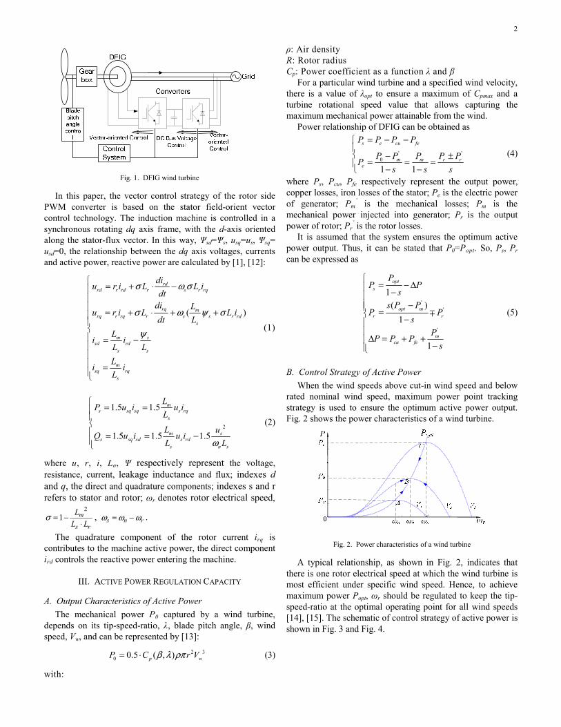
B. Control Strategy of Active Power When the wind speeds above cut-in wind speed and below
rated nominal wind speed, maximum power point tracking strategy is used to ensure the optimum active power output. Fig. 2 shows the power characteristics of a wind turbine.
Fig. 2. Power characteristics of a wind turbine
A typical relationship, as shown in Fig. 2, indicates that there is one rotor electrical speed at which the wind turbine is most efficient under specific wind speed. Hence, to achieve maximum power Popt, ωr should be regulated to keep the tip-speed-ratio at the optimal operating point for all wind speeds [14], [15]. The schematic of control strategy of active power is shown in Fig. 3 and Fig. 4.

3
I
P
D +
F
-
ωref
Wind speed
ωr irqref
风速(m/s)0.0 4.0 8.0 12.0 16.0
0.4M
0.8M
1.2M
1.6M
2.0M Po pt
Popt
Fig. 3. Rotor speed mode control
Fig. 4 Power mode control
The transient response of rotor speed mode control is fast and DFIG can achieve steady-state quickly. But, the output power will fluctuate or sag. Compared with rotor speed mode control, the transient response of power mode control is relatively slow, but power output is becoming smooth. At the same time, the reference depends on the wind speed value can not be measured because it is a fictitious wind speed related to the energy contained in the incident wind field. Therefore, power mode control and blade pitch angle control are chose to regulate active power output. There is a blade pitch angle control block available in PSCAD/EMTDC.
IV. REACTIVE POWER REGULATION CAPACITY
A. Reactive Power Limits According to (2) and (5), the approximated limit for the
reactive power is obtained: 2
2 2 2 2max( 1.5 ) (1.5 ) (1.5 )s m m
s s s r s rn s s s
U L LP Q U I U I
L L Lω+ + = ≤ (6)
22 2
max max
22 2
min max
2 2
1.5 (1.5 ) ( )1
1.5 (1.5 ) ( )1
( )1
opts ms s r
n s s
opts ms s r
n s s
opts n
PU LQ U I P
L L s
PU LQ U I P
L L s
PQ S P
s
ω
ω
⎧= − + − − Δ⎪
−⎪⎪⎪ = − − − − Δ⎨ −⎪⎪⎪ ≤ − − Δ⎪ −⎩
(7)
where Irmax is the maximum rotor current that can be driven by the rotor-side converter; Sn is the rated power of DFIG.
In commercial systems, the grid side inverter usually works with unity power factor, i.e., zero reactive power, so the total reactive power capability of the generator is equal to the stator reactive power capability. But in this paper, the grid side inverter reactive power capability is taken into
account. The approximated limit for the reactive power can be derived as follows:
'2 ' 2
max
'2 ' 2
min
( )[ ]
1
( )[ ]
1
opt mg g r
opt mg g r
s P PQ S P
s
s P PQ S P
s
⎧ −⎪ = −
−⎪⎨
−⎪= − −⎪ −⎩
∓
∓
(8)
where Sg is the rated power of the grid side inverter. The reactive powers limits of the DFIG wind turbine can be
represented as the sum of (7) and (8).
m x max max
min min min
a s g
s g
Q Q Q
Q Q Q
= +⎧⎪⎨ = +⎪⎩
(9)
Hence, the output reactive power limits can be obtained under different wind speed condition. In practical operation, Pm
’, Pr’, Pcu, Pfe are neglected to ensure a margin
of safety. Reference [7] has demonstrated that both steady state and dynamic stability limits are approximately equal.
B. Control Strategy of Reactive Power Currently, the reactive power control strategy of DFIG
wind turbine mainly includes constant power factor control strategy, constant terminal voltage control strategy and dynamic compensation control strategy.
(a) Constant power factor control strategy. When a small scale wind farm connects to the grid, a change of output will hardly affect the operational status. In that case, wind generators usually work with constant power factor, such as unity power factor. The constant power factor control block is shown in Fig. 5.
Fig. 5 Constant power factor control block
(b) Constant terminal voltage control strategy. When a wind farm is installed in remote, rural areas where the grids is weak or a wind farm is large enough, the voltage of integrated point sometimes fluctuates greatly. In its acute forms, voltage collapse will endanger the security and grid-connection of wind generators. Therefore, the reactive power is controlled to maintain voltage stability. The external-loop is controlled by constant voltage and the inner-loop is controlled by reactive power. The constant terminal voltage control block is shown in Fig. 6.
Fig. 6 Constant terminal voltage control block
4
(c) Dynamic compensation control strategy. In grid-
connected applications, dynamic compensation control strategy is implemented to provide in some cases compensation, to satisfy the reactive power requirement of local load or the grid by making full use of a DFIG wind turbine capacity of power regulation. The dynamic compensation control block is shown in Fig. 7.
Fig. 7 Dynamic compensation control block
For the last two control strategies, the reactive power limits should be considered and combined with the control objectives and the actual operation condition of the power system, in order to contribute to the voltage regulation and power compensation. Therefore, to ensure the utility and effectiveness of the developed and tested reactive power control, it can achieve operation optimization.
V. SIMULATION RESULTS The power regulation capacity simulation studies for a
2MW wind turbine were carried out. The control mode was selected for the maximum power point tracking and the reactive power compensation that based on the reactive power limits. The results illustrate how the developed wind farm controller controls the wind farm power production by considering the regulation capacity of the DFIG wind turbine in PSCAD/EMTDC environment.
Parameters of the system used for simulations are reported as follows: Turbine: R=40m, λopt=10.5, ρ=1.225kg/m3, rated wind speed is 13m/s. DFIG: The rated power of DFIG is 2MVA, rated voltage is 0.69kV, rs=0.0004pu, rr=0.02pu, Lm=6.92pu, Lσs=0.257pu, Lσr=0.295pu, Irmax=1.8KA, Sg=0.6MW.
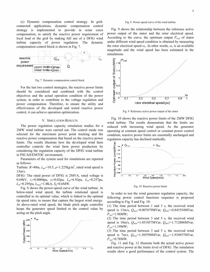
Fig. 8 shows the power-speed curve of the wind turbine. At below-rated wind speed, the turbine rotational speed is controlled to its optimal value, which is linked to the optimal tip speed ratio, to ensure that capture the largest wind energy. At above-rated wind speed, the blade pitch angle controller keeps the generator speed limited to the control value by acting on the pitch angle.
Fig. 8 Power-speed curve of the wind turbine
Fig. 9 shows the relationship between the reference active
power output of the stator and the rotor electrical speed. According to the curve, the optimum output Psref of stator under different wind speed condition is obtained by measuring the rotor electrical speed ωr. In other words, ωr is an available magnitude and the wind speed has been estimated in the simulations.
Fig. 9 Reference active power output of the stator
Fig. 10 shows the reactive power limits of the 2MW DFIG wind turbine. The results demonstrate that the limits are reduced with increasing wind speed. As the generator operating at constant speed control or constant power control condition, reactive power limits are essentially unchanged and regulation capacity has declined markedly.
Fig. 10 Reactive power limits
In order to test the wind generator regulation capacity, the following power control functions sequence is proposed according to Fig. 9 and Fig. 10: (1) The time period between 1 and 3 s, the received wind speed is 13m/s, Qmax=0.007679MVar, Qmin=-0.843554MVar, Popt=1.96MW; (2) The time period between 3 and 5 s, the received wind speed is 10m/s, Qmax=1.051857MVar, Qmin=-1.712806MVar, Popt=1.19MW; (3) The time period between 3 and 5 s, the received wind speed is 7m/s, Qmax=1.305598MVar, Qmin=-1.934937MVar, Popt=0.78MW.
Fig. 11 and Fig. 12 illustrate both the actual active power and reactive power at the limits level of DFIG. The simulation results show a good performance of the control system. The

5
specified references both for the active and reactive power are achieved properly to track the maximal wind energy and reactive power limits when the injected wind is changing.
Fig. 11 Output power that consider the upper limit of reactive power
Fig. 12 Output power that consider the lower limit of reactive power
Within the limits range, the reactive power requirement of local load or the grid can be satisfied. For example, when the reactive power requirement of grid is 1MVar, the simulation result is shown in Fig. 13. At 13m/s of the wind speed, Qmax=0.007679MVar. So it can only control its output according the limit. At 10m/s and 7m/s of the wind speed, the reactive power capacity can achieve the requirement.
Fig. 13 Output power that consider the power requirement of the grid
In practical, the information of the reactive power
requirement of the grid or the local users is feedback to the control system of wind farm. Then, compared with the reactive limits of the wind farm under the current circumstances, the reference reactive power output value of the whole wind farm is determined and distributed to each wind generator on the basis of its power regulation capacity.
VI. CONCLUSION The simulation results obtained when running the wind
generator at its ultimate state. Then, the results analysis demonstrates that the optimum active power to be generated
varies because of changes in wind speed, and the designed control laws are capable of keeping tracking the desired power. The reactive power capability limits of this generator are calculated for planning the reference reactive power, and the generator enables the flexible adjustment of reactive power between the limits. In practical experience, optimization of active and reactive power output and making full use of the regulation capacity have great significance in improving the stability of a grid-connected wind farm and its voltage, also in controlling the power flow and balance.
VII. ACKNOWLEDGMENT The authors acknowledge contribution from North China
Electric Power Research Institute.
VIII. REFERENCES [1] Chi Yongning, “Studies on the Stability Issues about Large Scale Wind
Farm Grid Integration,” D.E. dissertation, Dept. China Electric Power Research Institute, 2006.E. H. Miller, "A note on reflector arrays," IEEE Trans. Antennas Propagat., to be published.
[2] Pooler M.A., “Doubly-fed induction machine models for stability assessment of wind farms,” in Proc. 2003 IEEE Int. Power Tech Conf., Italy.
[3] Liu Qihui, He Yikang, and Zhao Rende, “Operation and Control of AC-Exited Variable-Speed Constant-Frequency Wind Power Generation System,” Transactions of China Electrotechnical Society, vol. 23, pp. 129-136, Jun. 2008.
[4] Rabelo B, and Hofmann W, “Optimal active and reactive power control with the doubly-fed induction generator in the MW-class wind-turbines,” in Proc. 2001 4th IEEE Int. Power Electronics and Drive Systems Conf., pp. 53-58.
[5] Lin Wenjing, “The Algorithm Study of the Controller in the Variable Speed Constant Frequency Doubly-Fed Wind Power Generation System,” M.S. dissertation, Dept. Electronics and Electric Engineering., Univ. Shanghai Jiao Tong, 2008.
[6] H. Camblong, I. Martinez de Alegria, M. Rodriguez, and G. Abad, “Experimental evaluation of wind turbines maximum power point tracking controllers,” Energy Conversion and Management, vol. 47, pp. 2846-2858, Nov. 2006.
[7] D. Santos-Martin, S. Arnaltes, and J.L. Rodriguez Amenedo, “Reactive power capability of doubly fed asynchronous generators,” Electric Power Systems Research, vol. 78, pp. 1837-1840, Nov. 2008.
[8] Shen Hong, Wang Weisheng, and Dai Huizhu, “Reactive Power Limit of Variable-Speed Constant-Frequency Wind Turbine,” Power System Technology, vol. 27, pp. 60-63, Nov. 2003.
[9] Lang Yongqiang, Zhang Xueguang, and Xu Dianguo, “Reactive Power Analysis and Control of Doubly Fed Induction Generator Wind Farm,” Proceedings of the CSEE, vol. 27, pp. 77-82, Mar. 2007.
[10] Yan Gangui, Wang Maochun, and Mugang, “Modeling of Grid-Connected Doubly-Fed Induction Generator for Reactive Power Static Regulation Capacity Study,” Transactions of China Electrotechnical Society, vol. 23, pp. 98-104, Jul. 2008.
[11] Luis M. Fernández, Francisco Jurado, and José Ramón Saenz, “Aggregated dynamic model for wind farms with doubly fed induction generator wind turbines,” Renewable Energy, vol. 33, pp. 129-140, Jan. 2008.
[12] Sergei P, Andrea T, and Alerto T, “Power control of a doubly fed induction machine via output feedback,” Control Engineering Practice, vol. 12, pp. 41-57, Jan. 2004.
[13] Ye Hangye, Control Technology of wind turbine, Beijing: China Machine Press, 2006, p. 138-140.
[14] Cai Zhi, Liu Jianzheng, and Wang Jian, “Simulation Research on Control Modes of Doubly-Fed Wind Power Generator Based on PSCAD,” Electrical Engineering, pp. 61-64, 2008.
[15] Zhao Yang, Zou Xudong, and Huang Daocheng, “Research on Excitation Control of Flexible Power Conditioner Doubly Fed Induction Machine,” in Proc. 2007 IEEE Power Electronics Specialists Conf., pp. 92-97.

6
IX. BIOGRAPHIES
Lei Sun was born in Yantai, Shandong Province, China in 1985. He received his B. S. degree from North China Electric Power University (NCEPU). Now he is a Master's Student of Electric Enpineering Department at NCEPU. His areas of interest include power system automation, power system analysis, and wind power generation.
Zengqiang Mi was born in Shijiazhuang, Hebei Province, China in 1960. Now he is a professor of Electric Engineering Department at North China Electric Power University (NCEPU). His areas of interest include power system automation, wind power generation, power system analysis, dynamic analysis of hybrid power system, and power system wide-area protection and control.
Yang Yu was born in Chongqing, China in 1982. He received the M.S. degree in power system and its automation from Xi’an Jiao tong University in 2008. Now he is working as an instructor in NCEPU. His interests mainly focus on Power system protection and control, wind power generation and power system analysis.
Wu Tao is a director of Electric Power System Research Division at North China Electric Power Research Institute Co., Ltd. He received the Ph.D. degree in power engineering from Xi’an Jiao tong University in 1997. He is currently involved in large system studies including power system modeling of generator excitation control system and governing system, real-time simulation, network planning, integration of wind generation to power systems and SSR mitigation studies.
Haifeng Tian was born in Fengzhen, Inner Mongolia, China in 1982. She received her B. S. degree from Inner Mongolia University of Technology. Now she is a Master's Student of Electric Engineering Department at NCEPU. His areas of interest include power system analysis, and wind power generation.