activated carbon blend ultra filtration membranes
TRANSCRIPT

International Journal of ChemTech Research CODEN( USA): IJCRGG ISSN : 0974-4290
Vol.6 , No.1, pp 565-577, Jan-March 2014
Development, Characterization and Application Studies of
Cellulose acetate – activated Carbon blend Ultra Filtration
Membranes
S. Velu, K. Rambabu *, L. Muruganandam
Chemical Engineering Division, School of Mechanical and Building Sciences, Vellore Institute of Technology University, Vellore 632014, India.
*Corres author: [email protected] Phone: –91-416-2202572, Mobile: –91-9962056278
Abstract: Ultrafiltration (UF) membrane separation is one of the largely used technologies for macro molecular solutes separation from aqueous streams especially for effluent treatment of process industries. A series of cellulose acetate (CA) blended with activated carbon, ultrafiltration (UF) membranes were prepared by the phase-inversion technique in 99.5/0.5, 98.5/1.5 and 97.5/2.5% blend compositions. Prepared membranes were subjected to morphological studies (using SEM and AFM), UF characterization study and thermal stability study. The blend membranes exhibited differences in morphologies, porosities and properties due to the activated carbon (AC) addition. With increase in AC concentration in the membrane composition, the membranes exhibited excellent water permeability, hydrophilicity, thermal strength and good anti-fouling ability. Results clearly indicated the improved characteristic features of 97.5% CA – 2.5% AC blend membrane in comparison with other synthesized UF membranes. Subsequently, performance study on the 97.5% CA – 2.5% AC blend membrane was carried out by subjecting the blend membrane for a typical tannery effluent treatment to study the reduction of BOD, COD and sulphates in the effluent. Performance results of the blend membrane were compared with the performance of pure CA membrane. Keywords: Ultra filtration, Cellulose acetate, Activated carbon, Membrane blending, Ultrafiltration characterization, Effluent treatment.
1. Introduction:
Recent advances in chemical process industries in terms of process optimization and process intensification has triggered the need for economic and efficient downstream separation process [1]. Membrane separation is a promising technology for the downstream processing especially with regard to effluent treatment of the process industries. Advantages such as ease of fabrication, ambient temperature operation, compact nature and low energy consumption has made membrane separation processes more popular for industrial separation applications when compared with other conventional separation processes [2]. The basic phenomena of membrane separation along with its commercial importance have been extensively reported in literature [2,3,4].

K. Rambabu et al /Int.J. ChemTech Res.2014,6(1),pp 565-577.
566
Porous polymeric materials and their blends have played an important role in membrane development for separation applications such as ultrafiltration (UF), microfiltration and nanofiltration [2,5,6]. Improvements in the polymer membrane properties in terms of porosity, hydrophilicity, thermal stability, mechanical strength, flux and solute rejection have been carried with addition of modifiers to the base polymer as well as by blending the base polymer with other porous polymeric material [2,3]. The starting material for membrane synthesis is to be selected in such a way that the material is tolerant to wide temperature range and pH range, apart from yielding membranes with wider range of pore sizes.
Separation of macromolecular solute from industrial effluent solutions can be achieved by UF process using a porous polymer membrane which allows the passage of solvent and smaller solutes but retains larger molecules. Asymmetric UF membranes based on cellulose acetate (CA) as the base polymer are widely used for this purpose. Advantages of CA membranes over other UF membranes include high hydrophilicity, diversified pore sizes, better salt rejection properties and renewable source of raw material for the membrane synthesis. However, pure CA membranes suffer from the limitation of lower fluxes. Blending the base CA polymer with other materials, results in membrane with enhanced improved physical properties [7–13]. Hvid et al [7] reported that hydrophilic surfaces are less prone to protein fouling and suggested methods to make the membrane surface more hydrophilic by using suitable modifiers as surface coatings. CA has been successfully blended with sulphonated polyether ether ketone [PEEK] polymer [8]. The resulting blend membrane showed increased pore size, higher flux and greater hydraulic resistance. CA–polyurethane blend membranes with polyvinylpyrrolidone (PVP) as an additive have been synthesized and applied to the rejection of proteins, including bovine serum albumin, egg albumin, pepsin and trypsin with the achievement of more than 90% rejection [9,10]. Because of the excellent film-forming properties of CA, preparation of polymeric blend membranes based on CA as base polymer was a potential idea for UF membrane development for commercial applications [11]. With Poly ethylene glycol (PEG) as additive, CA and low cyclic dimmer polysulfone blend membrane resulted in increased water flux, porosity and water content [12]. CA blended with polyethylene glycol UF membranes have also been investigated [13].
Commercial applications of activated carbon filters have been reported for gas phase separations especially for hydrogen separation from a steam reformer off gas and also for production of nitrogen from air [14]. Separation of carbon-di-oxide from methane was investigated using Acrylonitrile–butadiene–styrene (ABS) copolymer blended with activated carbon [15]. Activated carbon was effectively used as standalone filtration medium for biological separation purposes to study protein rejection studies at an enhanced flux rate [16]. Adsorption of low concentration dyes [17], removal of metal ions (Cu2+, Pb2+ and Ni2+) [18] and reduction in fouling effect [19] are certain salient advantages reported in literature for activated carbon blended micro filters and activated carbon cloths.
In this current study, a series of UF membranes with CA as base polymer and activated carbon (AC) as modifier have been synthesized with varying compositions. The prepared membranes have been characterized in terms of UF characterizations like pure water flux, hydraulic resistance, thermal stability analysis, water uptake and morphology characterizations using SEM & AFM. The blend membrane with better UF characterization was then subjected to textile industry effluent treatment to analyze its rejection properties and the results were compared with pure CA membrane’s performance.
2. Experimental Procedure:
2.1. Materials
Cellulose acetate (CA) (approximately 45% acetyl content – Ultrafiltration grade) was procured from Mysore Acetate & Chemical Co. Ltd., Karnataka, India. Activated carbon (AC) was procured from Capital carbon Pvt. Ltd., Gujarat, India. Dimethyl Formamide (DMF) solvent was obtained from The Precision Scientific Co (Cbe), Trichy, India. Poly ethyleneimine (PEI) was obtained from Triveni Interchem Private Limited, Vapi, India. The textile effluent, for the studying the membrane application for solute rejection, was obtained from a Textile mill located at Special Economic Zone (SEZ), Tirrupur, India. Freshly prepared deionized and distilled water was employed for the preparation of gelation bath. All the reagents and materials used in the membrane preparation process were of analytic grade and were used as such in the preparation process, without any further treatment.

K. Rambabu et al /Int.J. ChemTech Res.2014,6(1),pp 565-577.
567
2.2. Membrane synthesis
Asymmetric UF membranes, especially membranes with CA as base material, are predominately prepared by phase inversion technique [11,21,22]. This technique allows preparing membranes with wide range of morphological varieties in terms of differences in membrane thickness, pore size and pore size distribution [11,22].
The cast solution for the membrane preparation was prepared by dissolving required amounts of the CA and AC in DMF solvent as shown in Table 1. Calculated quantities of the CA polymeric powder and AC modifier in various weight ratios (attributing to a total weight of 4.375 g) were taken and dissolved in DMF solvent in a round bottom flask. The solvent DMF attributed to 82.5% weight composition of the cast solution which was the standard requirement for the complete dissolution of the polymeric powder and AC modifier mixture in the solution [23]. A blending period of 2 to 4 hours was given for the casting solution to attain homogeneity. Increase in the modifier concentration in the cast solution resulted in prolonged period for complete blending. During blending, the round bottom flask was subjected to slight heating for attaining homogeneity faster. The homogenous cast solution thus obtained was then cooled to room temperature for 30 minutes, to remove any air bubbles in the solution which would otherwise prove detrimental to the membrane structure.
The cast solution was then cast on a smooth glass plate with the help of a doctor’s blade. Prior to casting, a gelation bath consisting of distilled water (non-solvent) was prepared and the bath was ice-cooled to 10 oC. After 30 sec of solvent evaporation, just after casting, the glass plate along with the polymer film was immersed in the gelation bath. The skin layer formation of the asymmetric membrane took place mainly during the first 30 seconds of the solvent evaporation. After an hour of gelation, the membrane was removed from the gelation bath and thoroughly washed with distilled water to remove the residual solvent from the membrane. The above procedure was adopted for the preparation of each blend membrane of respective composition, as specified in Table 1. The membrane sheets were subsequently stored in distilled water containing 0.1% of formalin solution to prevent microbial growth.
2.3. Membrane Characterization
2.3.1. Morphology
Membrane morphology analysis provides an insight on the pore structure and the pore statistics of a given membrane, which in turn gives an idea on the potential performance of the membrane. Morphology analysis for the prepared blend membranes was done using scanning electron microscopy and atomic force microscopy.
Scanning electron microscopy (SEM) (Supra 55-Carl Zeiss, Germany) was used to analyze the morphology of the blend membranes. The membranes were cut into pieces of various sizes and mopped with filter paper. These pieces were immersed in liquid nitrogen for 20–30 s and were frozen. Frozen bits of the membranes were broken and kept in a desiccator. These membrane samples were used for SEM studies. SEM images were taken for top surface and cross-sectional surface of the blend membranes.
Atomic Force Microscopy (AFM) (NTMDT- Ntegra Prima Model, Ireland) was used to analyze small membrane samples taken from the prepared blend membranes. AFM characterization of a membrane is focused on the determination of the surface morphology and surface roughness thereby correlating the membrane structure with membrane properties, surface adhesion and membrane fouling. AFM gives the topographic images of membrane samples in 3D by scanning with a sharp tip over a surface. AFM images were taken for the synthesized blend membranes. Surface measurement parameters such as roughness average (Sa), surface skewness (Ssk) and surface kurtosis (Sku) values were obtained to compare the differences in the surface structures of the prepared UF blend membranes.
2.3.2. Water uptake
Water uptake is considered to be an important parameter for membrane characterization, since the pure water flux of the membrane can be predicted based on these results. Initially, the given blend membrane was vacuum dried in oven at 50 oC for 1 hour to remove surface moisture. The weight of the vacuum dried CA

K. Rambabu et al /Int.J. ChemTech Res.2014,6(1),pp 565-577.
568
100)( ×−=
w
dw
W
WWWC
blend membrane was then measured. Subsequently, the blend membrane was placed in a water bath for 24 h and the weight of the hydrated wet membrane was measured. The percentage water uptake was calculated by the equation:
where WC – water uptake (%), Ww and Wd (g) – wet and dry weight of the CA blend membranes respectively.
2.3.3. Pure water flux
Representative membrane samples, cut into an effective membrane area of 38.5 cm² were taken and placed in the stirred UF batch cell of 450 ml capacity. Prior to pure water flux measurements, the membrane samples were compacted at a pressure of 414 kPa to obtain the steady state flux. Membranes were then subjected to pure water flux measurements at transmembrane pressures of 69, 138, 207, 276, 345 and 414 kPa. The fluxes were measured under steady state flow. The permeate flux was determined using the equation:
where, Jw – permeate flux (lit m-2 h-1), Q – quantity of permeate (lit); A – membrane area (m2), ∆T – sampling time (h)
2.3.4. Membrane hydraulic resistance
Membrane hydraulic resistance is a measure of inherent resistance of membrane for the flux transport across it. To determine the membrane resistance (Rm), the pure water flux of a given blend membrane was measured at different transmembrane pressures of 69, 138, 207, 276, 345 and 414 kPa, after compaction. The hydraulic resistance of the given blend membrane was then evaluated from the inverse of the slope for the plot between water flux (Jw) and transmembrane pressure difference (∆P) for the given blend membrane.
2.3.5. Thermal stability analysis
Thermal stability analysis (Thermo gravimetric analysis) for a given blend membrane was carried out using STA 409PC Seiko Instrument Inc. Sample of the representative blend membrane (5 mg) was subjected to uniform heating from 50 oC to 450 oC with a constant heating rate of 10 oC/min under an inert (nitrogen) atmosphere. Prior to the analysis, the membrane sample was vacuum dried for 2 hours at 50 oC to remove moisture content present in it. The glass transition temperature for the representative blend membrane was also obtained from the thermal analysis.
2.3.6. Solute Rejection
Membrane performance study was carried out in terms of solute rejection analysis by subjecting the blend membrane for effluent treatment. Rejection studies (based on dead end filtration mode) was carried out in a UF stirred batch cell with an internal diameter of 76 mm, 450 ml capacity with Teflon coated magnetic paddle. Representative membrane sample, cut into an effective membrane area of 38.5 cm² was taken in the UF cell and was subjected to an applied pressure of 414 kPa. A constant agitation speed of 500 rpm was used for the paddle in order to reduce the concentration polarization and fouling effect on the membrane. The concentration of feed solution was kept constant. Permeate and reject streams were collected at defined time intervals in graduated tubes and the collected streams were analyzed for BOD, COD and sulphate content. The BOD, COD and sulphate content analysis of the feed, permeate and reject streams were carried out in the Instrumental & Analytical lab of Tamil Nadu Pollution Control Board (TNPCB).
TA
QJ w ∆
=

K. Rambabu et al /Int.J. ChemTech Res.2014,6(1),pp 565-577.
569
The solute rejection percentage (% SR) was calculated from the concentration of feed and permeate streams using the equation:
where, Cp and Cf are solute concentrations of permeate stream and feed stream, respectively.
Table 1: Compositions of cast solutions used for CA – AC blend UF membranes preparation
3. Results and Discussions:
The results of morphology analysis, UF characterization and thermal stability studies of the synthesized series of cellulose acetate (CA) – activated carbon (AC) blend membranes were compared with 100 % pure CA membrane to interpret the enhanced features of the blend membranes.
3.1. Morphology
In case of asymmetric membranes, the solute rejection mainly occurs in the upper skin layer and the flux is regulated by the pores present in the support layer. The CA – AC blend membranes showed better porosity, both in the skin as well as support layer, when compared to pure CA membrane. From the SEM images as shown in figure 1, it could be seen that there was uniform distribution of pores on the skin layer and the enhanced pore size on the support layer for the 97.5% CA – 2.5% AC blend membrane in comparison with pure CA membrane as well as other synthesized blend membranes.
AFM image depicts the roughness of the membrane which is characterized by the peak structures. The increase in roughness results in an increase in fouling which will in turn cause a fall in the flux rates [24]. As shown in figure 2, an average roughness of 95.33 nm was found in the case of 100% pure CA membrane, which is quite high. This is denoted by the large number of peaks distributed throughout the membrane. As a result, pure CA membrane tends to foul more, resulting in low flux transport. However, the AFM images of the blend membranes showed comparatively less peaks, indicating less roughness of the surface and thus the low fouling tendency than pure CA membrane, which in turn assures the potential of increased flux in the blend membranes. The 97.5% CA – 2.5% AC blend membrane appeared to be smoother with less number of peaks in comparison with pure CA membrane as well as other synthesized blend membranes.
Surface characterization parameters viz. roughness average (Sa), surface skewness (Ssk) and surface kurtosis (Sku) values for the AFM analyzed membranes are tabulated in Table 2. The results imply the better morphological features of 97.5% CA – 2.5% AC blend membrane.
Morphological studies on the synthesized blend membranes clearly indicate the potential nature of increased flux and decreased fouling due to the AC addition than the pure CA membrane. Results also imply the better morphological features of 97.5% CA – 2.5% AC blend membrane in comparison with other blend membranes.
Base Polymer Cellulose Acetate (in g)
Modifier Activated Carbon (in g)
Solvent Dimethyl Formamide (in ml)
4.353 (99.5% of solute)
0.022 (0.5% of solute)
21.7 (82.5% of solvent)
4.309 (98.5% of solute)
0.066 (1.5% of solute)
21.7 (82.5% of solvent)
4.266 (97.5% of solute)
0.109 (2.5% of solute)
21.7 (82.5% of solvent)
1001% ×
−=
f
p
C
CSR

K. Rambabu et al /Int.J. ChemTech Res.2014,6(1),pp 565-577.
570
Figure 1: SEM images of top surface (1.1, 1.3, 1.5 & 1.7) and cross-section (1.2, 1.4, 1.6 & 1.8) of pure and blend membranes a) 100% CA b) CA– AC (99.5/0.5%) c) CA– AC (98.5/1.5%) and d) CA– AC (97.5/2.5%)
1.1 1.2
1.3 1.4
1.5 1.6
1.7 1.8

K. Rambabu et al /Int.J. ChemTech Res.2014,6(1),pp 565-577.
571
Figure 2: AFM – 3D images (2.1, 2.3, 2.5 & 2.7) and 2D images (2.2, 2.4, 2.6 & 2.8) of) of pure and blend membrane a) 100% CA b) CA– AC (99.5/0.5%) c) CA– AC (98.5/1.5%) and d) CA– AC (97.5/2.5%)
2.1 2.2
2.3 2.4
2.5 2.6
2.7 2.8

K. Rambabu et al /Int.J. ChemTech Res.2014,6(1),pp 565-577.
572
Table 2: Roughness parameters of the pure and blend membranes
Membrane Roughness average (Sa) (in nm)
Surface skewness (Ssk) (in nm)
Surface Kurtosis (Sku) (in nm)
100% CA 95.3257 0.255461 1.54911
99.5% CA – 0.5% AC 68.3906 0.281928 1. 27142
98.5% CA – 1.5% AC 31.8563 0.237028 1.35452
97.5% CA – 2.5% AC 18.1756 0.226177 1.12289
3.2. Pure Water Flux, Hydraulic resistance and Water uptake
Results of ultrafiltration characterization tests which included pure water flux measurements at various transmembrane pressures; membrane hydraulic resistance measurement and water uptake measurement for the prepared blend membranes as well as the 100% pure CA membrane are presented in Table 3.
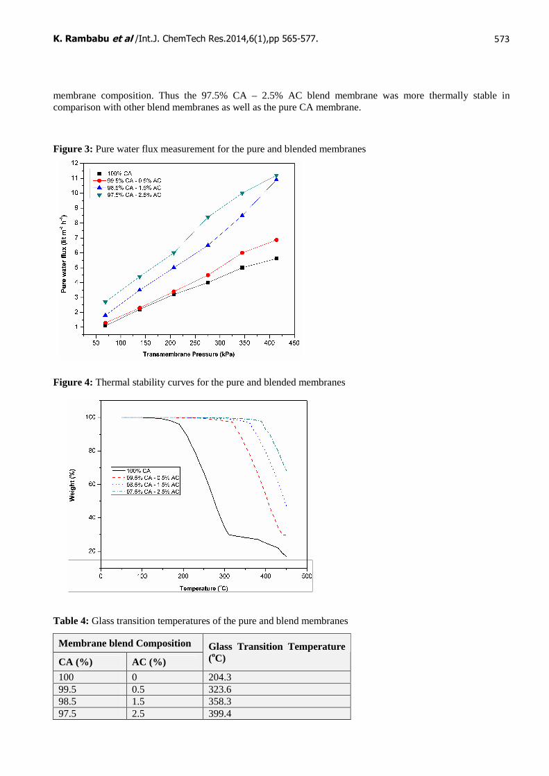
As shown in figure 3, pure water flux of the blend membranes were better than the pure CA membrane and recorded an increasing pattern with the increase in concentration of AC modifier which is due to the increased void structures in the support layer as shown by the morphological studies. Thus, the 97.5% CA – 2.5% AC blend membrane gave the maximum water flux as shown by the results presented in Table 3.
The membrane hydraulic resistance of the blend membranes recorded a decreasing trend with the increasing concentration of AC modifier which can be attributed to the increasing porosity. The increasing water uptake of the blend membranes with increase in AC modifier concentration is due to the increase in the number of pores as well as the hydrophilic nature of the AC modifier. Thus, the 97.5% CA – 2.5% AC blend membrane exhibited the lowest hydraulic resistance and better water uptake among the prepared blend membranes.
UF characterization tests on the synthesized blend membranes clearly demonstrated the enhanced water permeability, hydrophilicity and flux of the blend membranes in comparison to pure CA membrane. UF properties of the 97.5% CA – 2.5% AC blend membrane was superior among the other blend membranes as well as the pure CA membrane.
Table 3: UF characterization & Thermal stability results for the pure and blended membranes
3.3. Thermal stability
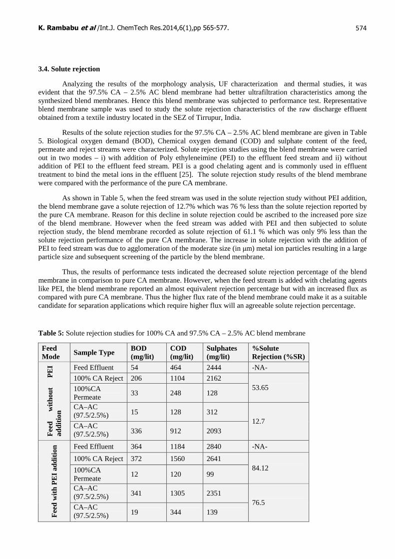
Results of the thermal analysis study clearly indicated the increased thermal stability of the blended membranes in comparison to pure CA membrane. As shown in figure 4, the weight loss percentage of the membrane (with increase in temperature) was reduced considerably by the addition of AC modifier, thus exhibiting the enhanced temperature tolerance of the blend membranes. The same phenomenon was also evident from the glass transition temperature (TG) measurement for the blend membranes. As shown in Table 4, the glass transition temperature of the blend membranes increased with the amount of the AC modifier in the
Membrane blend Composition
Pure Water flux (lit m-2 h-1)
CA (%)
AC (%)
69 kPa
138 kPa
207 kPa
276 kPa
345 kPa
414 kPa
Membrane Hydraulic Resistance (kPa m2 h lit-1)
Water uptake (%)
100 0 1.1 2.2 3.2 4 5 5.61 69.93 33.3 99.5 0.5 1.3 2.3 3.4 4.5 6 6.86 59.88 50 98.5 1.5 1.8 3.5 5 6.5 8.5 10.9 39.84 66.6 97.5 2.5 2.7 4.4 6 8.4 10 11.2 34.84 66.6
K. Rambabu et al /Int.J. ChemTech Res.2014,6(1),pp 565-577.
573
membrane composition. Thus the 97.5% CA – 2.5% AC blend membrane was more thermally stable in comparison with other blend membranes as well as the pure CA membrane.
Figure 3: Pure water flux measurement for the pure and blended membranes
Figure 4: Thermal stability curves for the pure and blended membranes
Table 4: Glass transition temperatures of the pure and blend membranes
Membrane blend Composition
CA (%) AC (%)
Glass Transition Temperature (oC)
100 0 204.3 99.5 0.5 323.6 98.5 1.5 358.3 97.5 2.5 399.4
K. Rambabu et al /Int.J. ChemTech Res.2014,6(1),pp 565-577.
574
3.4. Solute rejection
Analyzing the results of the morphology analysis, UF characterization and thermal studies, it was evident that the 97.5% CA – 2.5% AC blend membrane had better ultrafiltration characteristics among the synthesized blend membranes. Hence this blend membrane was subjected to performance test. Representative blend membrane sample was used to study the solute rejection characteristics of the raw discharge effluent obtained from a textile industry located in the SEZ of Tirrupur, India.
Results of the solute rejection studies for the 97.5% CA – 2.5% AC blend membrane are given in Table 5. Biological oxygen demand (BOD), Chemical oxygen demand (COD) and sulphate content of the feed, permeate and reject streams were characterized. Solute rejection studies using the blend membrane were carried out in two modes – i) with addition of Poly ethyleneimine (PEI) to the effluent feed stream and ii) without addition of PEI to the effluent feed stream. PEI is a good chelating agent and is commonly used in effluent treatment to bind the metal ions in the effluent [25]. The solute rejection study results of the blend membrane were compared with the performance of the pure CA membrane.
As shown in Table 5, when the feed stream was used in the solute rejection study without PEI addition, the blend membrane gave a solute rejection of 12.7% which was 76 % less than the solute rejection reported by the pure CA membrane. Reason for this decline in solute rejection could be ascribed to the increased pore size of the blend membrane. However when the feed stream was added with PEI and then subjected to solute rejection study, the blend membrane recorded as solute rejection of 61.1 % which was only 9% less than the solute rejection performance of the pure CA membrane. The increase in solute rejection with the addition of PEI to feed stream was due to agglomeration of the moderate size (in µm) metal ion particles resulting in a large particle size and subsequent screening of the particle by the blend membrane.
Thus, the results of performance tests indicated the decreased solute rejection percentage of the blend membrane in comparison to pure CA membrane. However, when the feed stream is added with chelating agents like PEI, the blend membrane reported an almost equivalent rejection percentage but with an increased flux as compared with pure CA membrane. Thus the higher flux rate of the blend membrane could make it as a suitable candidate for separation applications which require higher flux will an agreeable solute rejection percentage.
Table 5: Solute rejection studies for 100% CA and 97.5% CA – 2.5% AC blend membrane
Feed Mode Sample Type BOD
(mg/lit) COD (mg/lit)
Sulphates (mg/lit)
%Solute Rejection (%SR)
Feed Effluent 54 464 2444 -NA-
100% CA Reject 206 1104 2162
100%CA Permeate
33 248 128 53.65
CA–AC (97.5/2.5%) Reject
15 128 312
Fee
d w
itho
ut
PE
I ad
diti
on
CA–AC (97.5/2.5%) Permeate
336 912 2093 12.7
Feed Effluent 364 1184 2840 -NA-
100% CA Reject 372 1560 2641
100%CA Permeate
12 120 99 84.12
CA–AC (97.5/2.5%) Reject
341 1305 2351
Fee
d w
ith
PE
I ad
diti
on
CA–AC (97.5/2.5%) Permeate
19 344 139 76.5

K. Rambabu et al /Int.J. ChemTech Res.2014,6(1),pp 565-577.
575
4. Conclusions
A novel series of cellulose acetate membrane (CA) blended activated carbon (AC) ultrafiltration membrane was synthesized in varying compositions (CA/ AC: 100/0, 99.5/0.5, 98.5/1.5 and 97.5/2.5 %). Prepared membranes were subjected to morphology study, ultrafiltration characterization studies and thermal stability analysis. The blend membranes exhibited differences in morphologies, porosities and properties due to the activated carbon (AC) addition. With increase in AC concentration in the membrane composition, the membranes exhibited excellent water permeability, hydrophilicity, thermal strength and good anti-fouling ability. The 97.5% CA – 2.5% AC blend membrane reported remarkably better structural features (in terms of pore statistics & roughness), excellent UF characteristics and enhanced thermal stability among the synthesized blend membranes. This 97.5% CA– 2.5% AC blend membrane was directed to performance test by applying it to study the solute rejection characteristics of a textile industry effluent. The performance results of the blend membrane were compared with that of 100% pure CA membrane. Results clearly indicated the decreased solute rejection percentage of the blend membrane in comparison with pure CA membrane. However, when the feed stream was treated with chelating agent like PEI, the blend membrane reported an almost on par solute rejection percentage with an increased flux, as compared with pure CA membrane. Thus the 97.5% CA – 2.5% AC blend membrane is very promising to be a potential candidate for membrane separation applications which require higher flux rates with little compromised solute rejection percentage in comparison of pure CA membrane.
5. Acknowledgements
The authors thank Dr. G. Arthaneeswaran of National Institute of Technology (NIT) – Tirchy, Tiruchirappalli for permitting to use NIT’s membrane research laboratory facilities to prepare the blend membranes and characterize their properties. The authors also wish to thank the office of the Instrumental & Analytical lab of Tamil Nadu Pollution Control Board (TNPCB), Vellore for characterizing the feed, permeate and reject streams of the effluent treatment.
Appendix
List of symbols used:
% SR - Percentage solute rejection Jw - Pure water flux Q - Permeate quantity A - Membrane area ∆T - Sampling time WC - Water uptake Ww - Weight of wet membrane Wd - Weight of dry membrane Rm - Membrane hydraulic resistance ∆P - Transmembrane pressure difference Cf - Solute concentration in the feed Cp - Solute concentration in the permeate Sa - Surface roughness average Ssk - Surface skewness Sku - Surface kurtosis

K. Rambabu et al /Int.J. ChemTech Res.2014,6(1),pp 565-577.
576
References:
1. Jenck, J. F., Agterberg, F., & Droescher, M. J., Products and processes for a sustainable chemical industry: a review of achievements and prospects, Green Chemistry, 2004, 6, 544–556.
2. Cheryan, M., Ultrafiltration and microfiltration handbook, CRC press, Florida, 1998.
3. Crull A, Membranes for the Nineties: Highlighting Surface Modification Technology, Business Communications Co., Nonvalk, CT, 1990.
4. Harris, J. E., Johnson, R. N., In Encyclopedia of Polymer Science and Engineering, Wiley Publications, New York, 1988.
5. Balakrishnan M and Agarwal G.P, Protein fractionation in a vortex flow filter II: Separation of simulated mixtures, Journal of Membrane Science, 1996, 12, 75–84.
6. Lentsch S, Aimar P and Orozco J. L, Separation albumin–PEG: Transmission of PEG through ultrafiltration membranes, Biotechnology and Bioengineering, 41(1993), 1039–1047.
7. K.B. Hvid, P.S. Nielsen, F.F. Stengaard, Preparation and characterization of a new ultrafiltration membrane, Journal of Membrane Science, 1990, 53, 189–202.
8. G. Arthanareeswaran, K. Srinivasan, R. Mahendran, D. Mohan , M. Rajendran, V. Mohan., Studies on cellulose acetate and sulfonated poly(ether ether ketone) blend ultrafiltration membranes, European Polymer Journal, 2004, 40, 751–762.
9. M Sivakumar, R Malaisamy, C.J Sajitha, D Mohan, V Mohan, R Rangarajan, Preparation and performance of cellulose acetate–polyurethane blend membranes and their applications – II, Journal of Membrane Science, 2000, 169, 215–228.
10. M Sivakumar, R Malaisamy, C.J Sajitha, D Mohan, V Mohan, R Rangarajan, Ultrafiltration application of cellulose acetate–polyurethane blend membranes, European Polymer Journal, 1999, 335, 1647–1651.
11. S Loeb, S Sourirajan, Sea Water Demineralization by Means of an Osmotic Membrane, in: Advances in Chemistry, ACS publications, 1963, 38, Chapter 9, 117–132.
12. G. Arthanareeswaran, C. S. Latha, D. Mohan, M. Raajenthiren, K. Srinivasan. Studies on Cellulose Acetate/Low Cyclic Dimmer Polysulfone Blend Ultrafiltration Membranes and their Applications, Separation Science and Technology, 2006, 41, 2895–2912.
13. G. Arthanareeswaran, P. Thanikaivelan, K. Srinivasn, D. Mohan, M. Rajendran, Synthesis, characterization and thermal studies on cellulose acetate membranes with additive., European Polymer Journal, 2004, 40, 2153–2159.
14. Sircar, S., Golden, T. C., & Rao, M. B., Activated carbon for gas separation and storage, Carbon, 1996, 34, 1–12.
15. Anson, M., Marchese, J., Garis, E., Ochoa, N., & Pagliero, C., ABS copolymer-activated carbon mixed matrix membranes for CO2 / CH4 separation, Journal of membrane science, 2004, 243, 19–28
16. Li, Y. Z., He, Y. L., Liu, Y. H., Yang, S. C., & Zhang, G. J., Comparison of the filtration characteristics between biological powdered activated carbon sludge and activated sludge in submerged membrane bioreactors, Desalination, 2005, 174, 305–314
17. Lee, J. W., Choi, S. P., Thiruvenkatachari, R., Shim, W. G., & Moon, H., Submerged microfiltration membrane coupled with alum coagulation/powdered activated carbon adsorption for complete decolorization of reactive dyes, Water research, 2006, 40, 435–444.
18. Kadirvelu, K., Faur-Brasquet, C., & Cloirec, P. L., Removal of Cu (II), Pb (II), and Ni (II) by adsorption onto activated carbon cloths, Langmuir, 2000, 16, 8404–8409.
19. Ying, Z., & Ping, G., Effect of powdered activated carbon dosage on retarding membrane fouling in MBR, Separation and purification technology, 2006, 52, 154–160.
20. [21] Strathmann, H, et al., The formation mechanism of asymmetric membranes, Desalination, 1975, 16, 179–203.
21. Nath K, Membrane separation processes, PHI Learning Pvt. Ltd., New Delhi, 2008

K. Rambabu et al /Int.J. ChemTech Res.2014,6(1),pp 565-577.
577
22. Velu S, Muruganandam L, Arthanareeswaran G, Effect of Solvents on Performance of Polyethersulfone Ultrafilteration Membranes for Separation of Metal Ions, International Journal of Chemical and Analytical Science, 2011, 2, 82–86.
23. Hobbs, C., Hong, S., & Taylor, J, Effect of surface roughness on fouling of RO and NF membranes during filtration of a high organic surficial groundwater. Aqua- Journal of Water Supply: Research and Technology, 2006, 55, 559–570.
24. Saad DM, Cukrowska EM, Tutu H., Phosphonated cross-linked polyethylenimine for selective removal of uranium ions from aqueous solutions, Water Science & Technology, 2012, 66, 122-129.
*****