acs880 overide control program supplement...this supplement applies to the acs880 override control...
TRANSCRIPT

ABB industrial drives
SupplementACS880 override control program (option +N5450)

List of related manuals
You can find manuals and other product documents in PDF format on the Internet. See section Document library on the Internet on the inside of the back cover. For manuals not available in the Document library, contact your local ABB representative.
Drive firmware manuals Code (English)ACS880 primary control program firmware manual 3AUA0000085967ACS880 drives with primary control program, quick start-up guide
3AUA0000098062
ACS880 override control program manual 3AXD50000035977Supply unit firmware manualsACS880 diode supply control program 3AUA0000103295ACS880 IGBT supply control program firmware manual
3AUA0000131562
Option manuals and guidesACX-AP-x assistant control panels user’s manual 3AUA0000085685Drive composer Start-up and maintenance PC tool User’s manual
3AUA0000094606
Manuals and quick guides for I/O extension modules, fieldbus adapter, etc.

Supplement
ACS880 override control program (option +N5450)
3AXD50000035977 Rev AEN
EFFECTIVE: 2016-06-08
2016 ABB Oy. All Rights Reserved.
Table of contents
Quick start-up guide


Table of contents 5
Table of contentsList of related manuals . . . . . . . . . . . . . . . . . . . . . . . . . . . . . . . . . . . . . . . . . . . . . . . . . . . . . . . 2
1. Introduction to the manualContents of this chapter . . . . . . . . . . . . . . . . . . . . . . . . . . . . . . . . . . . . . . . . . . . . . . . . . . . . . . . 7Purpose of this guide . . . . . . . . . . . . . . . . . . . . . . . . . . . . . . . . . . . . . . . . . . . . . . . . . . . . . . . . . 7Applicability . . . . . . . . . . . . . . . . . . . . . . . . . . . . . . . . . . . . . . . . . . . . . . . . . . . . . . . . . . . . . . . . 7Safety . . . . . . . . . . . . . . . . . . . . . . . . . . . . . . . . . . . . . . . . . . . . . . . . . . . . . . . . . . . . . . . . . . . . 8Target audience . . . . . . . . . . . . . . . . . . . . . . . . . . . . . . . . . . . . . . . . . . . . . . . . . . . . . . . . . . . . . 8Contents . . . . . . . . . . . . . . . . . . . . . . . . . . . . . . . . . . . . . . . . . . . . . . . . . . . . . . . . . . . . . . . . . . 8Related documents . . . . . . . . . . . . . . . . . . . . . . . . . . . . . . . . . . . . . . . . . . . . . . . . . . . . . . . . . . 9
2. Quick start-up guideContents of this chapter . . . . . . . . . . . . . . . . . . . . . . . . . . . . . . . . . . . . . . . . . . . . . . . . . . . . . . 11Before you start . . . . . . . . . . . . . . . . . . . . . . . . . . . . . . . . . . . . . . . . . . . . . . . . . . . . . . . . . . . . 11Safety . . . . . . . . . . . . . . . . . . . . . . . . . . . . . . . . . . . . . . . . . . . . . . . . . . . . . . . . . . . . . . . . . . . 11Drive start-up . . . . . . . . . . . . . . . . . . . . . . . . . . . . . . . . . . . . . . . . . . . . . . . . . . . . . . . . . . . . . . 12
Pre-requisite . . . . . . . . . . . . . . . . . . . . . . . . . . . . . . . . . . . . . . . . . . . . . . . . . . . . . . . . . . . 12Override control start-up . . . . . . . . . . . . . . . . . . . . . . . . . . . . . . . . . . . . . . . . . . . . . . . . . . . . . 13
Override control program parameter settings . . . . . . . . . . . . . . . . . . . . . . . . . . . . . . . . . . 13
3. Default control connectionsContents of this chapter . . . . . . . . . . . . . . . . . . . . . . . . . . . . . . . . . . . . . . . . . . . . . . . . . . . . . . 15Default control connections for the override control program (BCU) . . . . . . . . . . . . . . . . . . . . 16Default control connections for the override control program (ZCU) . . . . . . . . . . . . . . . . . . . . 17
4. Program featuresContents of this chapter . . . . . . . . . . . . . . . . . . . . . . . . . . . . . . . . . . . . . . . . . . . . . . . . . . . . . . 19Overview of the override control program . . . . . . . . . . . . . . . . . . . . . . . . . . . . . . . . . . . . . . . . 19
Protection and maintenance . . . . . . . . . . . . . . . . . . . . . . . . . . . . . . . . . . . . . . . . . . . . . . . 20Temperature protection . . . . . . . . . . . . . . . . . . . . . . . . . . . . . . . . . . . . . . . . . . . . . . . . . . . 20Safety features . . . . . . . . . . . . . . . . . . . . . . . . . . . . . . . . . . . . . . . . . . . . . . . . . . . . . . . . . 20
Override control interface . . . . . . . . . . . . . . . . . . . . . . . . . . . . . . . . . . . . . . . . . . . . . . . . . . . . 21Override control functions . . . . . . . . . . . . . . . . . . . . . . . . . . . . . . . . . . . . . . . . . . . . . . . . . . . . 22Activating override mode . . . . . . . . . . . . . . . . . . . . . . . . . . . . . . . . . . . . . . . . . . . . . . . . . . . . . 24Speed or frequency reference . . . . . . . . . . . . . . . . . . . . . . . . . . . . . . . . . . . . . . . . . . . . . . . . . 25Activating override control mode in the supply unit . . . . . . . . . . . . . . . . . . . . . . . . . . . . . . . . . 26Diagnostics in INU . . . . . . . . . . . . . . . . . . . . . . . . . . . . . . . . . . . . . . . . . . . . . . . . . . . . . . . . . . 27Diagnostics in supply unit . . . . . . . . . . . . . . . . . . . . . . . . . . . . . . . . . . . . . . . . . . . . . . . . . . . . 27
5. ParametersContents of this chapter . . . . . . . . . . . . . . . . . . . . . . . . . . . . . . . . . . . . . . . . . . . . . . . . . . . . . . 29Terms and abbreviations . . . . . . . . . . . . . . . . . . . . . . . . . . . . . . . . . . . . . . . . . . . . . . . . . . . . . 30Summary of parameter groups . . . . . . . . . . . . . . . . . . . . . . . . . . . . . . . . . . . . . . . . . . . . . . . . 30
Safety

6 Table of contents
Parameter listing . . . . . . . . . . . . . . . . . . . . . . . . . . . . . . . . . . . . . . . . . . . . . . . . . . . . . . . . . . 3109 Override control and status . . . . . . . . . . . . . . . . . . . . . . . . . . . . . . . . . . . . . . . . . . . . . 3174 Override control . . . . . . . . . . . . . . . . . . . . . . . . . . . . . . . . . . . . . . . . . . . . . . . . . . . . . . 32
Parameters used by override control program . . . . . . . . . . . . . . . . . . . . . . . . . . . . . . . . . . . . 3411 Standard DIO, FI, FO . . . . . . . . . . . . . . . . . . . . . . . . . . . . . . . . . . . . . . . . . . . . . . . . . 3419 Operation mode . . . . . . . . . . . . . . . . . . . . . . . . . . . . . . . . . . . . . . . . . . . . . . . . . . . . . 3420 Start/stop/direction . . . . . . . . . . . . . . . . . . . . . . . . . . . . . . . . . . . . . . . . . . . . . . . . . . . 34
Changed firmware default values by override control program . . . . . . . . . . . . . . . . . . . . . . . 3522 Speed ref sel . . . . . . . . . . . . . . . . . . . . . . . . . . . . . . . . . . . . . . . . . . . . . . . . . . . . . . . . 3523 Speed ref ramp . . . . . . . . . . . . . . . . . . . . . . . . . . . . . . . . . . . . . . . . . . . . . . . . . . . . . . 3531 Fault functions . . . . . . . . . . . . . . . . . . . . . . . . . . . . . . . . . . . . . . . . . . . . . . . . . . . . . . . 35
6. Supply unit parameter dataContents of this chapter . . . . . . . . . . . . . . . . . . . . . . . . . . . . . . . . . . . . . . . . . . . . . . . . . . . . . 37Summary of parameter groups in supply unit . . . . . . . . . . . . . . . . . . . . . . . . . . . . . . . . . . . . . 37Parameter groups . . . . . . . . . . . . . . . . . . . . . . . . . . . . . . . . . . . . . . . . . . . . . . . . . . . . . . . . . . 38
109 Override control and status . . . . . . . . . . . . . . . . . . . . . . . . . . . . . . . . . . . . . . . . . . . . 38174 Override control . . . . . . . . . . . . . . . . . . . . . . . . . . . . . . . . . . . . . . . . . . . . . . . . . . . . . 38
7. Fault tracingContents of this chapter . . . . . . . . . . . . . . . . . . . . . . . . . . . . . . . . . . . . . . . . . . . . . . . . . . . . . 41Safety . . . . . . . . . . . . . . . . . . . . . . . . . . . . . . . . . . . . . . . . . . . . . . . . . . . . . . . . . . . . . . . . . . . 41Indications . . . . . . . . . . . . . . . . . . . . . . . . . . . . . . . . . . . . . . . . . . . . . . . . . . . . . . . . . . . . . . . 41
Warnings and faults . . . . . . . . . . . . . . . . . . . . . . . . . . . . . . . . . . . . . . . . . . . . . . . . . . . . . 41Warning messages in ACS880 primary control program . . . . . . . . . . . . . . . . . . . . . . . . . . . . 42Warning messages in the supply unit control programs . . . . . . . . . . . . . . . . . . . . . . . . . . . . . 42
8. Control chain diagramsContents of this chapter . . . . . . . . . . . . . . . . . . . . . . . . . . . . . . . . . . . . . . . . . . . . . . . . . . . . . 43Override control chain program for INU . . . . . . . . . . . . . . . . . . . . . . . . . . . . . . . . . . . . . . . . . 44Current and switching frequency limitations . . . . . . . . . . . . . . . . . . . . . . . . . . . . . . . . . . . . . . 45Override control chain program ISU . . . . . . . . . . . . . . . . . . . . . . . . . . . . . . . . . . . . . . . . . . . . 46
9. Example configurationsContents of this chapter . . . . . . . . . . . . . . . . . . . . . . . . . . . . . . . . . . . . . . . . . . . . . . . . . . . . . 47ACS880 INU and ISU IO control . . . . . . . . . . . . . . . . . . . . . . . . . . . . . . . . . . . . . . . . . . . . . . 48Drive fieldbus control . . . . . . . . . . . . . . . . . . . . . . . . . . . . . . . . . . . . . . . . . . . . . . . . . . . . . . . 49
Further informationProduct and service inquiries . . . . . . . . . . . . . . . . . . . . . . . . . . . . . . . . . . . . . . . . . . . . . . . . . 51Product training . . . . . . . . . . . . . . . . . . . . . . . . . . . . . . . . . . . . . . . . . . . . . . . . . . . . . . . . . . . 51Providing feedback on ABB manuals . . . . . . . . . . . . . . . . . . . . . . . . . . . . . . . . . . . . . . . . . . . 51Document library on the Internet . . . . . . . . . . . . . . . . . . . . . . . . . . . . . . . . . . . . . . . . . . . . . . 51
Introduction to the manual 7
1Introduction to the manual
Contents of this chapter
The chapter describes the contents of this manual. It also contains information on the applicability, safety and intended audience.
Purpose of this guide
This supplement describes the difference between ACS880 override control program and ACS880 primary control program. It also describes the additional override control program related parameters in the supply unit control programs. These are relevant only for those drives that have a separate supply unit.
Applicability
This supplement applies to the ACS880 override control program used as a part of the following control programs:
Control program Version
ACS880 primary control program 2.3x or later
ACS880 diode supply control program ADIFX v2.00.0.0 or later
ACS880 IGBT supply control program AISLX v2.2x or later
ACS880 IGBT supply control program 2Q ALHLX v2.2x or later

8 Introduction to the manual
Safety
Follow all safety instructions delivered with the drive.
• Read the complete safety instructions before you install, commission, or use the drive. The complete safety instructions are given at the beginning of the hardware manual for the single drives, or in the Safety instructions [3AUA0000102301 (English)] for the multidrives and multidrives modules.
• Read the software function specific warnings and notes before changing the default settings of the function. For each function, the warnings and notes are given in this manual in the section describing the related user-adjustable parameters.
Target audience
This supplement is intended for people who design, commission, or operate the drive system.
Contents
The manual consists of following chapters:
Quick start-up guide provides the basic start-up sequence of the drive and additional alternative checklists for starting up the drive.
Default control connections describes the default control connections of the ACS880 override control program.
Program features describes the features that are added to ACS880 override control program compared with ACS880 primary control program.
Parameters lists the parameter differences between ACS880 primary control program and ACS880 override control program.
Supply unit parameter data lists additional override function parameters for the supply control programs.
Fault tracing lists the additional warning and fault messages (including possible causes and corrective actions) specific to the Override control program.
Control chain diagrams presents the reference chains specific to the Override control program.
Example configurations presents the override control program IO control and fieldbus configurations.

Introduction to the manual 9
Cyber security disclaimer
This product is designed to be connected to and to communicate information and data via a network interface. It is Customer's sole responsibility to provide and continuously ensure a secure connection between the product and Customer network or any other network (as the case may be). Customer shall establish and maintain any appropriate measures (such as but not limited to the installation of firewalls, application of authentication measures, encryption of data, installation of anti-virus programs, etc) to protect the product, the network, its system and the interface against any kind of security breaches, unauthorized access, interference, intrusion, leakage and/or theft of data or information. ABB and its affiliates are not liable for damages and/or losses related to such security breaches, any unauthorized access, interference, intrusion, leakage and/or theft of data or information.
Related documents
See the List of related manuals on the inside of the front cover.

10 Introduction to the manual

Quick start-up guide 11
2Quick start-up guide
Contents of this chapter
This chapter contains the basic start-up sequence of the drive and additional alternative checklists for starting up the drive.
Before you start
Make sure the drive is mechanically and electrically installed as described in the appropriate Quick installation guide and/or Hardware manual.
Safety
WARNING! All electrical installation and maintenance work on the drive must be carried out by qualified electricians only.
Never work on the drive, the brake chopper circuit, the motor cable or the motor when power is applied to the drive. Always make sure by measuring that no voltage is actually present.
WARNING! Make sure that the machinery into which the drive with the Override control program is integrated fulfills the personnel safety regulations.
Note that the frequency converter (a Complete Drive Module or a Basic Drive Module, as defined in IEC 61800-2 with the Override control program), is not considered as a safety device mentioned in the European Machinery Directive and related harmonized standards. Thus, the personnel safety of the complete machinery must not be based on a specific frequency converter feature (such as the Override control program), but it has to be implemented as defined in the application specific regulations.

12 Quick start-up guide
Drive start-up
Pre-requisite
Before start-up, check that all control signals required for the activation of Override control mode are in “inactive” (false) state:
• DI5
• Fieldbus override control word bit 0 (parameter 09.01 Override control word)
In addition, do the following:
• Start-up the drive according to ACS880 primary control program quick start-up guide [3AUA0000098062 (English)].
• If synchronous reluctance motor is used, see also Supplement SynRM motor control program [3AXD50000026332 (English)]. With SynRM motor, set parameter 21.13 Autophasing mode = Standstill 1.
• Make sure that Override mode is inactivated in the supply unit control program (parameter 09.01, bit 1).

Quick start-up guide 13
Override control start-up
This section contains the startup instructions for a drive with the Override control program.
Override control program parameter settings
Safety
WARNING! Obey all safety instructions for the drive. Only qualified electricians are allowed to start up the drive.
Parameter settings
Restore the default parameter settings.
• 96.06 Parameter restore, select Restore defaults.
Set the speed or frequency references and limits in override mode.
• 74.03 Override speed ref 1 with DTC, scalar motor control mode (99.04).
• 74.04 Override speed ref 2 with DTC, scalar motor control mode (99.04).
• If you select Hz for the reference unit in the scalar motor control mode (19.20), set constant frequency references 74.05...74.06.
• 74.16...74.19 Override minimum and maximum speed and frequency limits.
Consider taking the output current limitation due to overtemperature in use.
• 74.07 Ambient temperature limit,
• 74.08 Inverter temperature limit and
• 74.09 Max current above temp limit.
For more information on the function, see section Override control interface (page 21).
Consider tuning the drive switching frequency value.
This is not a must: the factory default value works as it is. However, in certain cases you can also choose to tune the switching frequency to maximize either the motor load capacity or the drive load capacity. As a thumb rule:
• Increasing the switching frequency decreases motor losses (and temperature) and increases drive losses (and temperature).
• Decreasing the switching frequency increases motor losses (and temperature) and decreases drive losses (and temperature).

14 Quick start-up guide
Default control connections 15
3Default control connections
Contents of this chapter
The chapter describes default control connections of the ACS880 override control program for two possible control units (BCU and ZCU) used with ACS880 drives.

16 Default control connections
Default control connections for the override control program (BCU)
Drive-to-drive link XD2D
Drive-to-drive link
B 1A 2
BGND 3Shield 4
RS485 connection X485
Not in use
B 5A 6
BGND 7Shield 8
Relay outputs XRO1…XRO3Ready250 V AC / 30 V DC2 A
NC 11COM 12NO 13
Running250 V AC / 30 V DC2 A
NC 21COM 22NO 23
Faulted(-1)250 V AC / 30 V DC2 A
NC 31COM 32NO 33
Safe torque off XSTO, XSTO OUT
Safe torque off input. Both circuits must be closed for the drive to start.
OUT 1SGND 2
IN1 3IN2 4
Safe torque off output to inverter modules
IN1 5SGND 6
IN2 7SGND 8
Digital inputs XDIStop (0) / Start (1) DI1 1Forward (0) / Reverse (1) DI2 2Reset DI3 3Override constant speed or freq ref 1 (0) / ref 2 (1) DI4 4Activate override control (0---> On) DI5 5By default not in use. DI6 6Run enable DIIL 7Digital input/outputs XDIOInput: Deactivate override control (0-->1 = Off) DIO1 1Output: Running DIO2 2Digital input/output ground DIOGND 3Digital input/output ground DIOGND 4Auxiliary voltage output XD24+24 V DC 200 mA +24VD 5Digital input ground DICOM 6+24 V DC 200 mA +24VD 7Digital input/output ground DIOGND 8Ground selection switch DICOM=DIOGNDAnalog inputs, reference voltage output AI10 V DC, RL 1…10 kohm +VREF 1-10 V DC, RL 1…10 kohm -VREF 2Ground AGND 3Speed reference0(2)…10 V, Rin > 200 kohm
AI1+ 4AI1- 5
By default not in use.0(4)…20 mA, Rin = 100 ohm
AI2+ 6AI2- 7
Analog outputs AO
Motor speed rpm 0…20 mA, RL < 500 ohmAO1 1
AGND 2
Motor current 0…20 mA, RL < 500 ohmAO2 3
AGND 4External power input XPOW
24 V DC, 2.05 ATwo supplies can be connected for redundancy.
+24VI 1GND 2+24VI 3GND 4
Safety functions module connection X12Control panel connection X13Memory unit connection X205XETH Not in use
Fault
To inverter modules

Default control connections 17
Default control connections for the override control program (ZCU)
Fault
XPOW External power input 1 +24VI
24 V DC, 2 A2 GND
XAI Reference voltage and analog inputs1 +VREF 10 V DC, RL 1…10 kohm2 -VREF -10 V DC, RL 1…10 kohm3 AGND Ground4 AI1+ Speed reference
0(2)…10 V, Rin > 200 kohm5 AI1-6 AI2+ By default not in use.
0(4)…20 mA, Rin > 100 ohm7 AI2-XAO Analog outputs
1 AO1 Motor speed rpm0…20 mA, RL < 500 ohm2 AGND
3 AO2 Motor current0…20 mA, RL < 500 ohm4 AGND
XD2D Drive-to-drive link1 B
Drive-to-drive link2 A3 BGND
XRO1, XRO2, XRO3 Relay outputs1 NC Ready
250 V AC / 30 V DC2 A
2 COM3 NO1 NC Running
250 V AC / 30 V DC2 A
2 COM3 NO1 NC Faulted(-1)
250 V AC / 30 V DC2 A
2 COM3 NO
XD24 Digital interlock1 DIIL Digital interlock. By default, not in use.2 +24VD +24 V DC 200 mA3 DICOM Digital input ground4 +24VD +24 V DC 200 mA5 DIOGND Digital input/output ground
XDIO Digital input/outputs1 DIO1 Input: Deactivate override control (0-->1 = Off) 2 DIO2 Output: Running
XDI Digital inputs1 DI1 Stop (0) / Start (1) 2 DI2 Forward (0) / Reverse (1) 3 DI3 Reset4 DI4 Override constant speed or freq ref 1 (0) / ref 2 (1)5 DI5 Activate override control (0-->1 = On)6 DI6 Not in use as default
XSTOSafe torque off circuits must be closed for the drive to start. See Hardware manual of drive.
X12 Safety options connectionX13 Control panel connectionX205 Memory unit connection

18 Default control connections

Program features 19
4Program features
Contents of this chapter
This chapter describes the additional features of Override control program for the ACS880 primary control program.
Overview of the override control program
The override control program is used in critical applications like tunnel fans in emergency situations. The program maximizes the reliability to continue operation of the fans. It is possible to continue operation until the motor or drive cannot function anymore. The followings conditions are considered for operating the program:
• Ordinary start/stop commands are disabled from different sources. For example, control panel, I/O and fieldbus.
• Ordinary speed or frequency references are disabled. Only override speed or frequency references are valid.
• Override mode continues automatically after supply power break, even though external control cables to digital inputs are disconnected.
• The program contains two specific override speed references (constant speed values set by parameters) including direction of speed change by digital I/O or polarity of speed or frequency reference.
• In the Primary control program, control location Ext2 is reserved for the Override control when “active”.
• IEC programming (option +N8010) is not supported.

20 Program features
Protection and maintenance
The override program includes the following conditions for protection and maintenance:
• Most of the protections are disabled during override mode i.e. only the fatal faults will trip the drive. If some hardware based faults activate, automatic control unit booting resets fault when override mode is active.
• Protections are also disabled in drive with BCU controlled supply unit in override mode.
• Includes test mode where fault diagnostics or fieldbus is activated to help regular maintenance procedures.
Temperature protection
The override program includes the following conditions for temperature protections:
• There is a possibility to limit motor current in case of excessive ambient temperature or excessive drive/inverter temperature.
• Possibilities to adjust switching frequency in override mode effecting temperature rise of motor or drive/converter module.
• The control program can automatically limit the drive output current if the drive internal temperature or the drive ambient temperature increase excessively. You can define the temperature limits and the maximum current by parameters 74.07 Ambient temperature limit, 74.08 Inverter temperature limit and 74.09 Max current above temp limit. If you want to inactivate the limitation, use current value that exceeds the output current rating of a drive.
• Current limitation decreases the motor and the drive stress in occasional extreme temperature. It can even prevent a permanent damage due to overheating. For example, if you prevent the drive fault trip due to the motor overload protection function, you can still allow to decrease the motor load in exceptionally high temperature conditions as it can save the motor and avoid a complete operation break.
Safety features
The override program includes the following conditions for safety:
• STO function works normally during override control.
• Emergency stop function is always valid if activated by parameter or fieldbus control word.
• Functional safety options FSO-12, FSO-21 and FSE-31 are not supported.
Program features 21
Override control interface
The control program forces the control location to external control location Ext2, when the override control mode is active. During normal operation, that is when the override control is inactive, Ext1 and Ext2 can be used normally.
When the drive exits the Override control mode, the control unit is automatically booted and is ready to start in the normal mode.
Settings
Parameter group 74 Override control (page 32).
Warnings: -
Faults: -

22 Program features
Override control functions
Override control mode – deactivates possible fault trips and forces the control place to Ext2 (parameter 19.11 Ext1/Ext2 selection = Ext2) with fieldbus control MCW, Ref1 and Ref2 are not valid.
Start/stop and speed reference – The I/O control start/stop and speed references are not valid and local control device is not active for start/stop and speed reference.
• 19.14 Ext2 control mode = Speed (2)
• 19.17 Local control disable = Yes (1)
• 20.06 Ext2 commands = In1 Start (1)
• 20.07 Ext2 start trigger type = Level (1)
• 20.08 Ext2 in1 source = Selected (1)
• 20.12 Run enable 1 source = Selected (1)
• 20.19 Enable start command = Selected (1)
Override speed and frequency references are constant speed references defined with parameters 74.03...74.06. The values are saved to permanent memory when entered by control panel or Drive composer PC tool. Note that references from fieldbus are not saved to permanent memory. Override speed references are ramped to speed limits 30.11 Minimum speed and 30.12 Maximum speed.
ACS880
Ready RO1
Run RO2
No fault RO3
PLC
MCW: Start / Stop / Reset
Ref1: Speed reference
Main status word(includes: override status)
Override speed reference
MCW: Start / Stop / Reset
Ref1: Speed reference
CW
Ref1
Ref2
74.03 Override speed ref 1
Override
Motor speed
DI1 Start/Stop (*)
DI2 Direction
DI3 Reset
DI4 Override speed ref1 / ref2
DI5 Activate override
DI6 Motor overtemperature (*)
DIO1 Deactivate override
DIIL Run enable (*)
SW
Act1
Motor current Act2
6.11 Main status word
Motor speed
Motor current
Relay output
MPTC
Pt 100KTY-84 T
(*) Not active in override mode

Program features 23
Protection over malfunction – If non-resettable faults like malfunction in electronics becomes active, override application may restart the drive by booting the control unit.
Temperature limit – The control program activates current limitation function over +40 °C ambient temperature based on the ambient and drive temperature measurements. See parameters 74.07 Ambient temperature limit to 74.09 Max current above temp limit (page 32).
Settings
Parameters 19.14 Ext2 control mode (page 34) 19.17 Local control disable (page 34), 20.06 Ext2 commands (page 34), 20.07 Ext2 start trigger type (page 34), 20.08 Ext2 in1 source (page 34), 20.12 Run enable 1 source (page 34), 20.19 Enable start command (page 34), 74.07 Ambient temperature limit (page 32) and 74.09 Max current above temp limit (page 33).
Warnings: -
Faults: -
24 Program features
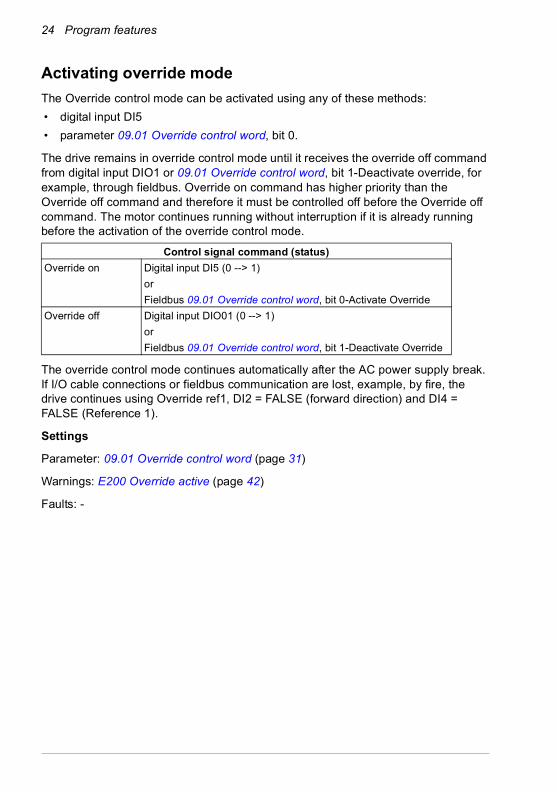
Activating override mode
The Override control mode can be activated using any of these methods:
• digital input DI5
• parameter 09.01 Override control word, bit 0.
The drive remains in override control mode until it receives the override off command from digital input DIO1 or 09.01 Override control word, bit 1-Deactivate override, for example, through fieldbus. Override on command has higher priority than the Override off command and therefore it must be controlled off before the Override off command. The motor continues running without interruption if it is already running before the activation of the override control mode.
The override control mode continues automatically after the AC power supply break. If I/O cable connections or fieldbus communication are lost, example, by fire, the drive continues using Override ref1, DI2 = FALSE (forward direction) and DI4 = FALSE (Reference 1).
Settings
Parameter: 09.01 Override control word (page 31)
Warnings: E200 Override active (page 42)
Faults: -
Control signal command (status)
Override on Digital input DI5 (0 --> 1)
or
Fieldbus 09.01 Override control word, bit 0-Activate Override
Override off Digital input DIO01 (0 --> 1)
or
Fieldbus 09.01 Override control word, bit 1-Deactivate Override

Program features 25
Speed or frequency reference
You can define the speed or frequency references, constant override speeds and frequencies for the override control:
Speed and frequency reference limits:
• 74.16 Override minimum speed limit
• 74.17 Override maximum speed limit
• 74.18 Override minimum frequency limit
• 74.19 Override maximum frequency limit
Constant override speeds and frequencies:
• Parameter 74.03 Override speed ref 1 with asynchronous, permanent magnet and SynRM motors
• Parameter 74.04 Override speed ref 2 with asynchronous, permanent magnet and SynRM motors
• Parameter 74.05 Override frequency ref 1 with scalar motor control mode and Hz reference selected
• Parameter 74.06 Override frequency ref 2 with scalar motor control mode and Hz reference selected
• Digital input DI4 selects either ref 1 (FALSE) or ref 2 (TRUE) of 74.03...74.06.
• Digital input DI2 is used to direction control (FALSE = forward, TRUE = backward) in Normal and override mode.
• When DI2 = FALSE, Override speed/freq references 1 and 2 are multiplied by 1
• When DI2 = TRUE, Override speed/freq references 1 and 2 are multiplied by -1
Settings
Parameter group 74 Override control (page 32).
Warnings: -
Faults: -

26 Program features
Activating override control mode in the supply unit
High-power ACS880 products have separate inverter and supply units. For using override control applications:
• you can activate or inactivate the override control mode in the inverter with the Override control program.
• the inverter activates or inactivates the override control function in the supply unit according its own status.
There is a communication link (DDCS) between the supply unit and inverter unit. The inverter unit controls the supply unit using the control word (CW) bit 12. See parameters 6.40 and 6.41.
When you activate the override control in the supply unit, it remains active until the override off command is given from digital input DIO1, through DDCS from INU or through fieldbus.
Override control mode automatically continues after the AC power supply break.
Note: The LSU does not contain STO function, but can still close the STO connector.
Settings
Parameters 09.02 Override status word (page 31) and 109.01 Override control word (page 38).
Warnings: -
Faults: -
Control signal command (status)
Override on Parameter 06.39 Internal state machine LSU CW user, bit 0 from INU to LSU (6.40 LSU CW user bit 0 = 09.02 Override status word, bit 4-Override activation request).
Digital input DI5 (0 --> 1)
or
Fieldbus 109.01 Override control word, bit 0-Activate Override.
Override off Parameter 06.39 Internal state machine LSU CW user bit 1 from INU to LSU (6.41 LSU CW user bit 1 = 09.02 Override status word bit 5-Override deactivation request)
Digital input DIO01 (0 --> 1)
or
Fieldbus 109.01 Override control word, bit 1-Deactivate Override.

Program features 27
Diagnostics in INU
Parameter 09.02 Override status word, bit 0-Override active and bit 1-Override test mode status can be connected to:
• relay or digital output in parameter group 10 and group 11 by using signal 09.02 Override status word, bit 0-Override mode active.
• free bits of 6.11 Main status word for fieldbus by parameters 6.29...6.33.
Settings
Parameter 09.02 Override status word (page 31).
Warnings: -
Faults: -
Diagnostics in supply unit
Parameter 109.02 Override status word, bit 0-Override active and bit 1-Override test mode status can be connected to:
• relay or digital output in parameter group 110 and group 111 by using signal 109.02 Override status word, bit 0-Override mode active.
• free bits of 106.11 Main status word for fieldbus by parameters 106.29...106.33.
Settings
Parameter 109.02 Override status word (page 38).
Warnings: -
Faults: -

28 Program features

Parameters 29
5Parameters
Contents of this chapter
This chapter lists the parameter difference between ACS880 override control program and ACS880 primary control program. For the description of parameters that are the same in both programs, see ACS880 primary control program firmware manual [3AUA0000085967 (English)].

30 Parameters
Terms and abbreviations
Summary of parameter groups
Term Definition
Actual signal Type of Parameter that is the result of a measurement or calculation by the drive, or contains status information. Most actual signals are read-only, but some (especially counter-type actual signals) can be reset.
Def (In the following table, shown on the same row as the parameter name)The default value of a Parameter.Note: Certain drive hardware or optional equipment may require different default values.
FbEq16 (In the following table, shown on the same row as the parameter range, or for each selection)16-bit fieldbus equivalent: The scaling between the value shown on the panel and the integer used in communication when a 16-bit value is selected for transmission to an external system.A dash (-) indicates that the parameter is not accessible in 16-bit format.
Other The value is taken from another parameter.Choosing “Other” displays a parameter list in which the user can specify the source parameter.
Other [bit] The value is taken from a specific bit in another parameter.Choosing “Other” displays a parameter list in which the user can specify the source parameter and bit.
Parameter Either a user-adjustable operating instruction for the drive, or an Actual signal.
p.u. Per unit
Group Contents Page
09 Override control and status Control word and status word related to the override control program.
31
11 Standard DIO, FI, FO Configuration of digital input/outputs and frequency inputs/outputs. 34
19 Operation mode Selects the local and external control location source. 34
20 Start/stop/direction Start/stop/direction and run/start/jog enable signal sourceselection.
34
22 Speed ref sel The default value of the following parameters are changed by the override control program.
35
23 Speed ref ramp The default value of the following parameters are changed by the override control program.
35
31 Fault functions The default value of the following parameters are changed by the override control program.
35
74 Override control Override specific parameter settings. 32
Parameters 31
Parameter listingNo. Name/Value Description Default;
FbEq (16b/32b)
09 Override control and status
Control word and status word related to the override control program.See section Activating override mode (page 24).
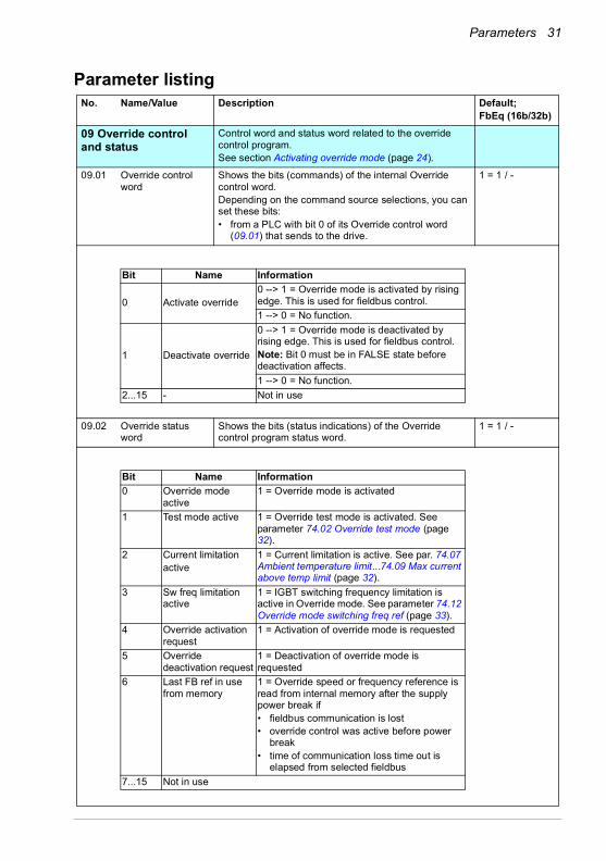
09.01 Override control word
Shows the bits (commands) of the internal Override control word. Depending on the command source selections, you can set these bits:• from a PLC with bit 0 of its Override control word
(09.01) that sends to the drive.
1 = 1 / -
09.02 Override status word
Shows the bits (status indications) of the Override control program status word.
1 = 1 / -
Bit Name Information
0 Activate override0 --> 1 = Override mode is activated by rising edge. This is used for fieldbus control.
1 --> 0 = No function.
1 Deactivate override
0 --> 1 = Override mode is deactivated by rising edge. This is used for fieldbus control.Note: Bit 0 must be in FALSE state before deactivation affects.
1 --> 0 = No function.
2...15 - Not in use
Bit Name Information
0 Override mode active
1 = Override mode is activated
1 Test mode active 1 = Override test mode is activated. See parameter 74.02 Override test mode (page 32).
2 Current limitationactive
1 = Current limitation is active. See par. 74.07 Ambient temperature limit...74.09 Max current above temp limit (page 32).
3 Sw freq limitation active
1 = IGBT switching frequency limitation is active in Override mode. See parameter 74.12 Override mode switching freq ref (page 33).
4 Override activation request
1 = Activation of override mode is requested
5 Override deactivation request
1 = Deactivation of override mode is requested
6 Last FB ref in use from memory
1 = Override speed or frequency reference is read from internal memory after the supply power break if• fieldbus communication is lost • override control was active before power
break• time of communication loss time out is
elapsed from selected fieldbus
7...15 Not in use

32 Parameters
74 Override control Override control specific parameter settings.See sections Override control interface (page 21), Faults: - (page27),
74.01 Override status Shows the Override status. This information is saved during power fail to flash memory and returned in next power on.
0 Override mode is inactive. 0
1 Override mode is active. 1
74.02 Override test mode Activates/inactivates the Override control test mode. The fault diagnostics can be activated for test purposes when the Override is already activated.A warning TEST MODE is activated to warn that this settings are used only temporary to check condition of drive system. This parameter value is not saved to permanent memory.
0
Bit 0 Override test mode.
Bit 1...15 Not in use.
74.03 Override speed ref 1
Defines the Override speed reference 1 when speed (rpm) type of reference is used if DI4 is off.
0 rpm
-30000.00...30000 rpm
Speed reference in rpm. See par. 46.01; - / 100 = 1 rpm
74.04 Override speed ref 2
Defines the Override speed reference 2 when speed (rpm) type of reference is used if DI4 is on.
0 rpm
-30000.00...30000 rpm
Speed reference in rpm. See par. 46.01; - / 100 = 1 rpm
74.05 Override frequency ref 1
Defines the Override frequency reference 1 when frequency (Hz) type of reference is selected in scalar mode by parameter 19.20 Scalar control reference unit.
0 Hz
-500.00...500.00 Hz Frequency reference in Hz. See par. 46.02;- / 100 = 1 Hz
74.06 Override frequency ref 2
Defines the Override frequency reference 2 when frequency (Hz) type of reference is selected in scalar mode by parameter 19.20 Scalar control reference unit.
-500.00...500.00 Hz Frequency reference in Hz. See par. 46.02;- / 100 = 1 Hz
74.07 Ambient temperature limit
Defines the ambient temperature limit where drive current is limited by ramping to a value of parameter 74.09 Max current above temp limit (page 33), when 1.31 Ambient temperature rises above this limit.
41 oC
-40...120 oC Ambient temperature limit. 1 = 1°C / 1 = 1°C
74.08 Inverter temperature limit
Defines the inverter temperature limit where the output current is limited to parameter 74.09 Max current above temp limit (page 33), when 5.11 Inverter temperature rises above this limit.
100 %
-40... 160 oC Relative inverter temperature limit. 1 = 1% / 1 = 1%

Parameters 33
74.09 Max current above temp limit
Defines the maximum current above the temperature limit.The maximum current when override mode is active and either temperature limit is reached. See parameters 74.07 Ambient temperature limit and 74.08 Inverter temperature limit (page 32). Power unit type limits the maximum value.
PU specific maximum value
0...30000 A Maximum current in override mode. 1 = 1A / 1 = 1A
74.12 Override mode switching freq ref
Defines the override mode switching frequency reference.The value is written to 97.01 Switching frequency reference when override mode is activated. Note: Minimum and maximum limits in switching frequencies reference are hardware dependent in different frames.
HW specific. See 74.10.
1.000...16.000 kHz Switching frequency reference. 1000 = 1kHz /1000 = 1kHz
74.16 Override minimum speed limit
Minimum speed reference limit in override mode. -1500.00rpm
-30000.00...
30000.00 rpm
Override minimum speed limit. See par. 46.01;- / 100 = 1rpm
74.17 Override maximum speed limit
Maximum speed reference limit in override mode. 1500.00 rpm
-30000.00...
30000.00 rpm
Override maximum speed limit. See par. 46.01;- / 100 = 1 rpm
74.18 Override minimum frequency limit
Defines the minimum frequency reference limit in override mode if frequency (Hz) type of reference is selected in scalar control by parameter19.20 Scalar control reference unit. As a default, scalar control uses rpm.
-50.00Hz
-500.00...500.00 Hz Override minimum frequency limit. See par. 46.02;- / 100 = 1Hz
74.19 Override maximum frequency limit
Defines the maximum frequency reference limit in override mode if frequency (Hz) type of reference is selected in scalar control by parameter 19.20 Scalar control reference unit. As a default, scalar uses rpm.
50.00 Hz
-500.00...500.00 Hz Override maximum frequency limit. See par. 46.02;- / 100 = 1 Hz
74.20 Control unit boot delay
Defines the time delay (Ton) for the drive to perform restarting of control unit (xCU) software. The counting time begins when any non-resettable fault becomes active. This is used to reset possible permanent type of faults like over voltage, under voltage, earth fault, over current, and short circuit or other abnormal conditions detected by hardware which cannot be masked off in override mode.
30 s
0 ... 240 s Time delay 1 = 1s / 1 = 1 s

34 Parameters
Parameters used by override control program
The following parameters of the ACS880 primary control program are used with Override mode activated.
Note: These parameters are not user-adjustable. No. Name/Value Description Default;
FbEq (16b/32b)
11 Standard DIO, FI, FO Configuration of digital input/outputs and frequency inputs/outputs.
Forced value
11.05 DIO1 function Deactivates the override mode.DIO function is used as a fixed digital input.
Input (1)
19 Operation mode Selects the local and external control location source. Forced value
19.11 Ext1/Ext2 selection Used by the override control program. Ext2 (1)
19.14 Ext2 control mode Used by the override control program. Speed (2)
19.17 Local control disable
Disables local control.If the drive is locally controlled and when the override mode is activated, the drive is switched to remote control using Ext2 control place.
Yes (1)
20 Start/stop/direction Start/stop/direction and run/start/jog enable signal sourceselection.
Forced value
20.06 Ext2 commands Used by the override control program. In1 Start (1)
20.07 Ext2 start trigger type
Used by the override control program. Level (1)
20.08 Ext2 in1 source Used by the override control program. Selected (1)
20.12 Run enable 1 source
Used by the override control program. Selected (1)
20.19 Enable start command
Used by the override control program. Selected (1)

Parameters 35
Changed firmware default values by override control program
The following default parameter settings of the ACS880 primary control program are changed during the override mode.
Note: These parameters are not user-adjustable.
No. Name/Value Description Default;FbEq (16b/32b)
22 Speed ref sel The default value of the following parameters are changed by the override control program.
Default value
22.22 Const speed sel1 Default value changed from DI5 to Not selected. Not selected (0)
23 Speed ref ramp The default value of the following parameters are changed by the override control program.
Default value
23.11 Ramp set selection Default value changed from DI4 to Acc/Dec time 1. Acc/Dec time 1 (0)
31 Fault functions The default value of the following parameters are changed by the override control program.
Default value
31.12 Autoreset selection Default value changed from 0000h to 0400h. Bit 10-Selectable fault
31.13 User selectable fault
Default value changed to Line side unit faulted. 0x7583
31.14 Number of trials Default value changed to value 1. 1

36 Parameters

Supply unit parameter data 37
6Supply unit parameter data
Contents of this chapter
This chapter describes the Override control program specific parameters for the supply unit control programs. These parameters are not included in the supply unit control program manuals. This chapter is relevant only if there is a separate supply unit in the drive.
Summary of parameter groups in supply unitGroup Contents Page
109 Override control and status
Shows the control word and status word related to the override control program in supply unit.
38
174 Override control Override specific parameter settings related to the override control program in supply unit.
38

38 Supply unit parameter data
Parameter groupsNo. Name/Value Description FbEq
109 Override control and status
Shows the control word and status word related to the override control program in supply unit.See section Activating override control mode in the supply unit (page 26).
109.01 Override control word
Shows the bits (commands) of the internal Override control word. Depending on the command source selections, you can set these bits:• from a PLC with bit b0 of its Override control word (09.01)
that it sends to the drive.
1 = 1
109.02 Override status word
Shows the bits (status indications) of the Override control program status word.
1 = 1
174 Override control Override specific parameter settings related to the override control program in supply unit.
174.01 Override status Shows the Override status. This information is saved during power fail to flash memory and returned in next power On.
0 Override mode is inactive. 0
1 Override mode is active. 1
174.02 Override test mode Activates/inactivates the Override control test modeThe fault diagnostics can be activated for test purposes when Override is already activated.
0
Bit 0 Override test mode.
Bit 1...15 Not in use.
Bit Name Information
0 Activate override0 --> 1 = Override mode is activated by rising edge. This is used for fieldbus control.
1 --> 0 = No function.
1 Deactivate override
0 --> 1 = Override mode is deactivated by rising edge. This is used for fieldbus control.
1 --> 0 = No function. Bit 0 state has no effect for deactivating.
2...15 - Not in use
Bit Name Information
0Override mode active
1 = Override mode is activated
1 Test mode active1 = Override test mode is activated. See parameter 174.02 Override test mode (page 38).
2...15 - Not in use

Supply unit parameter data 39
174.20 Control unit boot delay
Defines the time delay (Ton) for the drive to perform restarting of control unit (xCU) software. Counting of the time begins when any non-resettable fault becomes active. This is used to reset possible permanent type of faults like over voltage, under voltage, earth fault, over current, and short circuit or other abnormal conditions detected by the hardware which cannot be masked off in override mode.
20 s
0 ... 240 s Time delay. 1 = 1s

40 Supply unit parameter data

Fault tracing 41
7Fault tracing
Contents of this chapter
The chapter lists the warning and fault messages (including possible causes and corrective actions) which differ from ACS880 primary control program described in ACS880 primary control program firmware manual [3AUA0000085967 (English)] and supply unit control programs listed in ACS880 diode supply control program [3AUA0000103295 (English)] and ACS880 IGBT supply control program firmware manual [3AUA0000131562 (English)].
Safety
WARNING! Only qualified electricians are allowed to service the drive. Read the Safety instructions on the first pages of the hardware manual for the single drives, or in the Safety instructions [3AUA0000102301 (English)] for the
multidrives and multidrives modules before working on the drive.
Indications
Warnings and faults
A warning or fault message on the panel display indicates abnormal drive status. Most of the warnings and faults causes can be identified and corrected using this information. If not, contact your local ABB representative.

42 Fault tracing
Warning messages in ACS880 primary control program
Warning messages in the supply unit control programs
The following are the warning messages generated in supply unit control programs.
Code Warning Cause What to do
E200 Override active Indicates that override mode is activated by I/O or through fieldbus.
Deactivate override control when the situation is over.
E201 Override TEST MODE Indicates that override test mode is activated by parameter 74.02 Override test mode.
Deactivate override control when the situation is over. Note: Test mode is for temporary test only, the value in parameter 74.02 is not saved to flash memory.
Code Warning Cause What to do
D200 Override active Indicates that override mode is activated by supply unit I/O, through DDCS from INU or fieldbus.
Deactivate override control when situation is ready.
D201 Override TEST MODE Indicates that override test mode is activated by parameter 174.02 Override test mode.
Deactivate override control when situation is over.Note: Test mode is for temporary test to indicate possible faults. The value in parameter 174.02 is not saved to flash memory. After the next power-on, test mode is not valid.

Control chain diagrams 43
8Control chain diagrams
Contents of this chapter
The chapter presents the override control program reference chain diagrams of the drive. The control chain diagrams can be used to trace how parameters interact and where parameters have an effect within the drive parameter system.

44 Control chain diagrams
Override control chain program for INU
S R
9.02
bit
0 O
verr
ide
mod
e ac
tive
OR
OR
74.0
1 O
verri
de s
tatu
sP
ower
fail
savi
ngS
avin
gR
esto
re74
.01
Ove
rrid
e st
atus
9.02
bit
4 O
verri
de a
ctiv
atio
n re
ques
t
DI5
9.01
bit
0
DIO
1
9.01
bit
1
War
ning
E20
0:O
verr
ide
activ
e
Set
dom
inan
t
9.02
bit
5 O
verr
ide
deac
tivat
ion
requ
est
Eve
nt s
yste
m
74.0
2 O
verr
ide
test
mod
e
74.2
0 C
ontro
l uni
t boo
t del
ayxC
U b
ootin
gfu
nctio
n
9.02
bit
1 Te
st m
ode
activ
e&
LIM
ITE
R74
.17
Ove
rrid
e m
axim
um s
peed
lim
it
74.0
4 O
verr
ide
spee
d re
f 2
74.0
3 O
verr
ide
spee
d re
f 1
74.1
6 O
verri
de m
inim
um s
peed
lim
it
Spe
ed li
mita
tion
-30.
11 M
inim
um s
peed
, -3
0.12
max
imum
spe
ed
LIM
ITE
R74
.19
Ove
rride
max
imum
freq
lim
it
74.0
6 O
verri
de fr
eque
ncy
ref 2
74.0
5 O
verr
ide
frequ
ency
ref 1
74.1
8 O
verid
e m
inim
um fr
eq li
mit
Freq
lim
itatio
n-3
0.13
Min
imum
freq
uenc
y-3
0.14
Max
imum
freq
uenc
y
DI4
DI4
&Fa
ult d
isab
ling
Test
mod
e
96.0
8 C
ontro
l boa
rd b
oot
Faul
t
Ove
rrid
e ac
tive
War
ning
E20
1:O
verr
ide
TES
T M
OD
E
DI2 MU
L-1
DI2 MU
L-1

Control chain diagrams 45
Current and switching frequency limitations
Cur
rent
and
sw
itchi
ngfre
quen
cy li
mita
tion
Sw
itchi
ng fr
eq
Sw
itch
freq Ti
me
LIM
ITE
RC
urre
nt
Tem
p
74.0
7 A
mbi
en te
mpe
ratu
re li
mit
74.0
8 In
verte
r tem
pera
ture
lim
it
74.0
9 M
ax c
urre
nt a
bove
tem
p lim
it
74.1
2 O
verr
ide
mod
e sw
itchi
ng fr
eq re
f
Ambi
ent t
empe
ratu
re
Inve
rter t
empe
ratu
re
Ove
rrid
e ac
tive
9.02
bit
2 C
urre
nt li
mita
tion
activ
e
9.02
bit
3 S
w fr
eq li
mita
tion
activ
e

46 Control chain diagrams
Override control chain program ISU
S R
109.
02 b
it 0
Ove
rrid
e m
ode
activ
e
OR
OR
174.
01 O
verr
ide
stat
usP
ower
fail
savi
ngS
avin
gR
esto
re17
4.01
Ove
rrid
e st
atus
DI5
109.
01 b
it 0
MC
W b
it 12
DIO
1
109.
01 b
it 1
War
ning
D20
0:O
verr
ide
activ
e
Set
dom
inan
t
Eve
nt s
yste
m
174.
02 O
verr
ide
test
mod
e
174.
20 C
ontro
l uni
t boo
t del
ayxC
U b
ootin
gfu
nctio
n
109.
02 b
it 1
Test
mod
e ac
tive
&
&Fa
ult d
isab
ling
Test
mod
e
196.
08 C
ontro
l boa
rd b
oot
Faul
t
Ove
rrid
e ac
tive
War
ning
D20
1:O
verr
ide
TEST
MO
DE

Example configurations 47
9Example configurations
Contents of this chapter
This chapter presents the override control program IO control and fieldbus configurations.

48 Example configurations
ACS880 INU and ISU IO control
AC
S88
0 IN
U
DI1
Sta
rt/St
op (*
)
DI2
Dire
ctio
n
DI3
Res
et
DI4
Ove
rrid
e sp
eed
ref1
/ re
f2
DI5
Act
ivat
e ov
errid
e
DI6
Mot
or o
verte
mpe
ratu
re (*
)
DIO
1 D
eact
ivat
e ov
errid
e
DIIL
Run
ena
ble
(*)
+24V
Rea
dy R
O1
Run
R
O2
No
faul
t R
O3
Ove
rrid
e ac
tivat
ed D
IO2
To c
ontro
l sys
tem
AC
S88
0-04
, -14
, -17
, -34
and
-37
driv
e I/O
con
trol
AC
S88
0 IS
U
DI1
Tem
p fa
ult (
*)
DI2
Run
/ en
able
(*)
DI3
MC
B fb
DI4
DI5
Act
ivat
e ov
errid
e
DI6
Res
et
DIO
1 D
eact
ivat
e ov
errid
e
DIIL
(*)
Rea
dy R
O1
Run
R
O2
No
faul
t R
O3
Ove
rrid
e is
act
ivat
ed a
nd
deac
tivat
ed in
sup
ply
unit
via
inte
rnal
DD
CS
link
.
Inte
rnal
DD
CS
link
with
fibr
e op
tic c
able
s
3-ph
ase
AC
sup
ply
From
Con
trol
syst
em
MP
TCP
t 100
KTY
-84
T
(*) N
ot a
ctiv
e in
ove
rrid
e m
ode
Example configurations 49
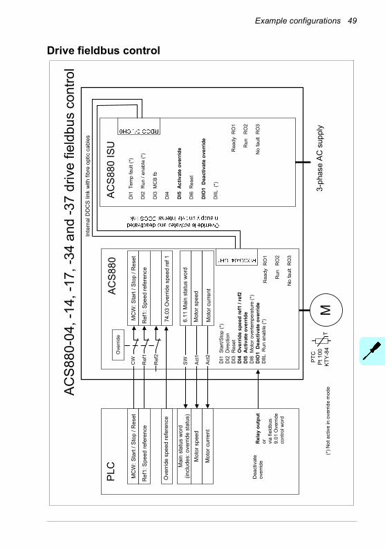
Drive fieldbus control
ACS
880-
04, -
14, -
17, -
34 a
nd -3
7 dr
ive
field
bus
cont
rol
AC
S88
0 IS
U
DI1
Tem
p fa
ult (
*)
DI2
Run
/ en
able
(*)
DI3
MC
B fb
DI4
DI5
Act
ivat
e ov
errid
e
DI6
Res
et
DIO
1 D
eact
ivat
e ov
errid
e
DIIL
(*)
Rea
dy R
O1
Run
R
O2
No
faul
t R
O3
Inte
rnal
DD
CS
link
with
fibr
e op
tic c
able
s
3-ph
ase
AC
sup
ply
MP
TCP
t 100
KTY
-84
T
AC
S88
0
Rea
dy R
O1
Run
R
O2
No
faul
t R
O3
PLC
MC
W: S
tart
/ Sto
p / R
eset
Ref
1: S
peed
refe
renc
e
Mai
n st
atus
wor
d(in
clud
es: o
verr
ide
stat
us)
Ove
rrid
e sp
eed
refe
renc
e
MC
W: S
tart
/ Sto
p / R
eset
Ref
1: S
peed
refe
renc
e
CW
Ref
1
Ref
2
74.0
3 O
verr
ide
spee
d re
f 1
Ove
rride
Mot
or s
peed
SW
Act
1
Mot
or c
urre
ntA
ct2
6.11
Mai
n st
atus
wor
d
Mot
or s
peed
Mot
or c
urre
nt
Rel
ay o
utpu
tor vi
a fie
ldbu
s 9.
01 O
verr
ide
cont
rol w
ord
DI1
Sta
rt/St
op (*
)D
I2 D
irect
ion
DI3
Res
etD
I4 O
verr
ide
spee
d re
f1 /
ref2
DI5
Act
ivat
e ov
errid
eD
I6 M
otor
ove
rtem
pera
ture
(*)
DIO
1 D
eact
ivat
e ov
errid
eD
IIL R
un e
nabl
e (*
)
Dea
ctiv
ate
over
ride
(*) N
ot a
ctiv
e in
ove
rrid
e m
ode

50 Example configurations

Further information
Product and service inquiries
Address any inquiries about the product to your local ABB representative, quoting the type designation and serial number of the unit in question. A listing of ABB sales, support and service contacts can be found by navigating to www.abb.com/searchchannels.
Product training
For information on ABB product training, navigate to new.abb.com/service/training.
Providing feedback on ABB manuals
Your comments on our manuals are welcome. Navigate to new.abb.com/drives/manuals-feedback-form.
Document library on the Internet
You can find manuals and other product documents in PDF format on the Internet at www.abb.com/drives/documents.

www.abb.com/driveswww.abb.com/drivespartners
3AXD50000035977 Rev A (EN) 2016-06-08
Contact us