acrp fact sheets – deicing...
TRANSCRIPT

Deicing Practices
AIRPORTCOOPERATIVE RESEARCH PROGRAMACRP
FACT SHEETS
Sponsored by the Federal Aviation Administration
FACT SHEETSDeicing Practices #1–41
ACRP Report 14Deicing Planning Guidelines and Practices for Stormwater Management Systems
A I R P O R T C O O P E R A T I V E R E S E A R C H P R O G R A M 2009
Deicing Fact Sheets
These Fact Sheets are prepared for each of the identified deicing practices.They are organized into the five categories mentioned in “Deicing PracticeCategories,” Chapter 3: aircraft deicing source reduction; airfield pavement deicing source reduction; deicing runoff containment/collection; deicing runofftreatment/recycling; and deicing runoff system components.
Special note on costs: Where available, specific costs of equipment and otherwell-defined elements are provided in the Fact Sheets to give the reader a senseof the magnitude of costs. These estimated cost numbers should not be used forplanning purposes without verifying current local costs.
Aircraft Deicing Source ReductionThe purpose of these practices is to reduce the amount of pollutants generated byaircraft deicing activities, either by using products with reduced environmentalimpacts or by reducing the amounts of deicing products required to achieve and maintain safe flight operations. It should be noted that U.S. aircraft operatorsmust obtain FAA Flight Standards approval for certain proposed source reduc-tion Fact Sheets prior to selection and implementation.
Fact Sheet 1. Aircraft-Deicing Product Selection
Fact Sheet 2. Storage and Handling of Aircraft-Deicing Materials
Fact Sheet 3. Proactive Anti-Icing
Fact Sheet 4. Blending to Temperature
Fact Sheet 5. Forced Air/Hybrid Deicing
Fact Sheet 6. Infrared Deicing Technology
Fact Sheet 7. Physical Removal
Fact Sheet 8. Hangared Parking
Fact Sheet 9. Hot Water Deicing
Fact Sheet 10. Enclosed Deicing Bucket
Fact Sheet 11. Enhanced Weather Forecasting
Fact Sheet 12. Holdover Time Determination Systems
Fact Sheet 13. Aircraft Deicer Use Tracking
Fact Sheet 14. Aircraft Reduced Operations
Fact Sheet 15. Tempered Steam Technology
iii
Airfield Pavement Deicing Source ReductionThe purpose of these Fact Sheets is to reduce the amount of pollutants generatedby airfield pavement–deicing activities, either by use of products with reducedenvironmental impacts or by reduction in the amounts of deicing products required to achieve and maintain safe flight operations.
Fact Sheet 16. Airfield Pavement-Deicing Product Selection
Fact Sheet 17. Storing and Handling of Airfield Deicing/Anti-Icing Agents
Fact Sheet 18. PDM Application Technology
Fact Sheet 19. Heated Pavement
Fact Sheet 20. Airfield Deicers—Physical Removal
Deicing Runoff Containment/CollectionThe role of these Fact Sheets is to provide methods for isolating, collecting, and containing storm water runoff from deicing activities. In most instances, these practices are implemented to address aircraft deicing runoff.
Fact Sheet 21. Centralized Deicing Facilities
Fact Sheet 22. Apron Collection Systems
Fact Sheet 23. Glycol Collection Vehicles
Fact Sheet 24. Block-and-Pump Systems
Fact Sheet 25. Airfield Drainage Planning/Design/Retrofit
Fact Sheet 26. Deicer-Laden Snow Management
Deicing Runoff System ComponentsThese technologies represent components of systems that may be imple-mented in various locations, and serving different purposes, in any given system.
Fact Sheet 27. Portable Tanks
Fact Sheet 28. Modular Tanks
Fact Sheet 29. Ponds
Fact Sheet 30. Permanent Tanks
Fact Sheet 31. Manual and Automated Diversion Valves
Fact Sheet 32. Real-Time Monitoring Technology
Fact Sheet 33. Catch Basin Inserts/Valves
iv DEICING FACT SHEETS
Deicing Runoff Treatment/RecyclingThese practices provide alternatives for disposing of deicing runoff that has been collected and contained, and is not suitable for controlled discharge to receiving waters.
Fact Sheet 34. POTW Discharge
Fact Sheet 35. Anaerobic Fluidized Bed Reactor
Fact Sheet 36. Reciprocating Subsurface Treatment
Fact Sheet 37. Moving Bed Bioreactor Treatment System
Fact Sheet 38. Sequencing Batch Reactor
Fact Sheet 39. Natural Treatment Systems
Fact Sheet 40. Membrane Filtration
Fact Sheet 41. Glycol Recovery
DEICING FACT SHEETS v

FACT SHEET 1
Aircraft-Deicing Product Selection
1. DescriptionPurposeThis practice considers opportunities to use alternative aircraft-deicingproducts that have a reduced environmental impact, primarily in terms ofthe biochemical oxygen demand (BOD) found in the freeze-point depressantsand aquatic toxicity associated with additives required to meet certification specifications.
Product selection is typically the responsibility of aircraft operators and theircontractors.
TechnologyAll aircraft deicing and anti-icing fluids (ADFs and AAFs) must be certified asmeeting the following Aerospace Materials Specifications published by SAE:
• 1424 Deicing/Anti-Icing Fluid, Aircraft, SAE Type I
• 1428 Fluid, Aircraft Deicing/Anti-icing, Non-Newtonian, SAE Types II, III, and IV
Each manufacturer of aircraft-deicing fluids has its own proprietary formulations,the environmental characteristics of which may vary from others. Currently, onlyethylene glycol (EG)–based or propylene glycol (PG)–based aircraft fluids areused at a commercial level. Both of these glycols have a relatively high BODcontent, with EG having a somewhat lower BOD than PG. The additive packages,which affect primarily the aquatic toxicity of each product, vary more significantlyamong the formulations. Guidance on the environmental properties is sometimesprovided in manufacturer literature for each product, but it is not always consis-tent or comparable between products.
The fluid manufacturers have been steadily improving their products with respectto aquatic toxicity and elimination of toxic components in the additive packages.Therefore, it is important to get the most current product information on the deicersthat are being used or considered.
There are several ongoing efforts to develop ADFs and AAFs with reducedenvironmental impacts. The Department of Defense’s Strategic EnvironmentalResearch and Development Program (SERDP) and Environmental SecurityTechnology Certification Program (ESTCP) have been funding research intoenvironmentally friendly aircraft deicers for the past decade. To date, three ADFshave come out of these programs, none of which has been fully qualified for use.The goal of ACRP’s ongoing 02-01 research project is to identify the sources of
ACRP Report 14 April 2009
SOURCE REDUCTION
Containment/Collection
System Components
Treatment/Recycling
1

toxicity in currently available deicing formulations and develop alternatives withmore environmentally friendly profiles. This project is expected to be completedin 2009 and produce several alternative formulations suitable for commercializa-tion. It is uncertain if, or when, any of these fluids will become commerciallyavailable.
Documented PerformanceThe U.S. military and some airports have mandated the use of only PG-basedaircraft fluids. This bias toward PG-based fluids seems counterintuitive givenits BOD content, but other environmental considerations have driven thetrend. Specifically, in the 1990s, industry and the military moved away from EG-based fluids because of ethylene glycol’s mammalian toxicity and its listing as ahazardous air pollutant subject to release reporting under the ComprehensiveEnvironmental, Response, Compensation, and Liability Act (CERCLA) and theEmergency Planning and Community Right-to-Know Act (EPCRA). In contrastto these industry trends, Dallas/Ft. Worth International Airport reported encour-aging the use of EG-based fluids specifically to reduce BOD loading from air-craft deicing. This facility disposes of all collected runoff, so recycling is not aconsideration.
At least one airport (Oslo) has taken the step of formally banning the use ofADFs and AAFs containing benzotriazoles because of Norwegian environmen-tal regulations. These chemicals are used as corrosion inhibitors in some fluidformulations and have been implicated as a major source of aquatic toxicity inthose fluids. There were no reports identified of North American airports takingsimilar steps.
2. Implementation ConsiderationsApplicability AssessmentThe primary key to applicability of this practice is the ability of aircraft operators to purchase and use SAE-certified deicing products based onimproved environmental characteristics. Flexibility in this regard will bedependent on site-specific weather and operational conditions, which requirespecific deicer characteristics, and organizational constraints that may affectprocurement practices. Also, any change in deicers must be accompanied byrevisions to the aircraft operator’s FAA-approved snow and ice control plan.
The potential for benefits from changing aircraft deicers may be evaluated by comparing the environmental characteristics of products currently beingused against available alternatives in the context of existing facility-specificenvironmental concerns.
Where glycol recycling is used or planned, there will be a strong economicmotivation for using PG-based fluids because the value of recovered glycolfrom runoff containing only PG-based fluids is significantly greater than thatof a mixed waste stream.
2 FACT SHEET 1
April 2009 ACRP Report 14

Regulatory ConsiderationsThe primary regulatory considerations regarding this practice are: (1) choice of alternatives is constrained to SAE-certified products and (2) any changes in product use must be incorporated in revised FAA-approved snow and ice control plans as well as associated training andoperational activities.
Planning and Design ConsiderationsProduct selection by an aircraft operator begins with identifying certifiedproducts that are reliably available in the quantities required and within thetime constraints. The identified list of products is then evaluated with respectto operator and industry experience with the product, ground support equip-ment fleet mix and compatibility with the product, and the need for and timingof employee retraining.
Other considerations include the following:
• Airport policies restricting the type of glycol that can be used at that facility.
• Implications to recycling programs that depend on using a PG-based fluid.
• Potential for increased management and reporting requirements associatedwith EG being regulated under Toxic Chemical Release and CERCLAreportable quantity regulations.
• The logistics of product substitution, which will include consuming or dis-posing of existing stockpiles of old fluids and cleaning tanks and refillingthem with the new product.
• Modifying and distributing deicing plans to reflect the new product and train-ing employees on the new plan and product.
• The environmental characteristics of the product.
Integration with Other Fact SheetsProduct selection can be combined with all other practices. There may be oppor-tunities to reduce the need for collection and treatment through use of deicerswith improved environmental characteristics (for example, lower BOD orreduced aquatic toxicity).
Operation and Maintenance ConsiderationsFor this practice to be effective, the aircraft operator should plan on revisingdeicing plans to reflect the new product and providing product-specific training todeicing personnel.
With the exception of changes required to the deicing plans, equipment opera-tion and maintenance requirements should not change significantly.
FACT SHEET 1 3
ACRP Report 14 April 2009
3. CostsCapital CostsThe only capital costs that might be incurred would be if the new product is notcompatible with existing storage and application equipment.
Operations and Maintenance CostsThe primary source of changes to operational and maintenance costs would bedifferences in cost of the new product compared to the previously used one.
4 FACT SHEET 1
April 2009 ACRP Report 14
FACT SHEET 2
Storage and Handling of Aircraft-Deicing Materials
1. DescriptionPurposeThis practice includes protocols or guidelines for the storage and handling of air-craft deicing materials, with the primary purpose of reducing the contaminationof stormwater by deicing/anti-icing materials.
Aircraft operators or their deicing contractors are normally responsible forimplementation of this practice.
TechnologySpecific goals for the storage and handling of deicing/anti-icing materialsinclude maintaining product integrity, using and storing products effectively,and minimizing exposure of the materials to stormwater. Personnel responsiblefor the storage and handling of these materials should be trained in stormwaterpollution prevention and follow protocols and procedures consistent with theairport’s stormwater pollution prevention plan (SWPPP) and deicer manage-ment program.
To maintain the integrity and effectiveness of deicing/anti-icing materials, theymust be stored, handled, and applied in a manner consistent with chemical-specific instructions provided by the manufacturer on the material safety datasheet (MSDS). Materials with reduced effectiveness may require larger appli-cation volumes or frequent reapplication, thus increasing the potential forstormwater pollution.
In general, aircraft anti-icing fluid, or AAF (classified as either a Type II or aType IV fluid by SAE), has more specialized requirements for storage andhandling than does aircraft deicing fluid, or ADF (classified as a Type I fluidby SAE). The high viscosity of AAF may be damaged by improper handlingor storage methods, which can potentially reduce the holdover time betweenapplications. Thickeners in AAF may be damaged by ultraviolet light and cer-tain metal ions and thus AAF requires storage in opaque tanks constructed ofstainless steel, coated steel, polyethylene, or opaque fiberglass. AAF agentsalso require careful heating to protect fluid viscosity. Any transfer of deicersthrough dedicated pipes and pumping equipment should be accomplishedaccording to manufacturers’ specifications. Anecdotal information from oneairport indicates that piping cannot contain 90° bends because they increasethe likelihood of freezing.
ACRP Report 14 April 2009
SOURCE REDUCTION
Containment/Collection
System Components
Treatment/Recycling
1
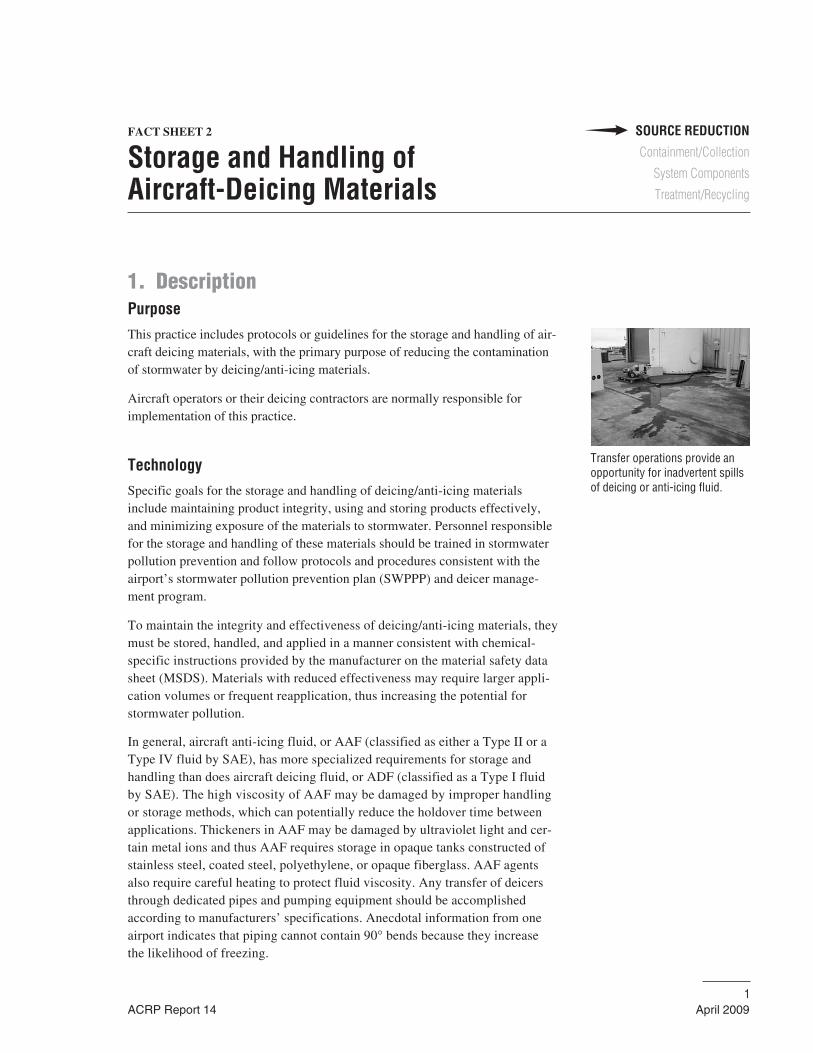
Transfer operations provide anopportunity for inadvertent spillsof deicing or anti-icing fluid.
Documented PerformanceQuantified benefits of establishing storage and handling protocols for aircraftdeicing materials have not been explicitly documented or measured. However,airports have reported reduced unexplained glycol releases during transfer andfewer unexplained occurrences of elevated deicer concentrations outside desig-nated deicing areas with the implementation of this practice. Generally, benefitsmay be expected in terms of decreased deicer discharges to surface water andpotentially decreased deicing stormwater management costs.
The success of this practice at an individual airport can be evaluated by compar-ing the frequency of unexplained or unexpected deicer releases before and afterimplementing storage and handling practices.
2. Implementation ConsiderationsApplicability AssessmentThis practice is applicable to any airport where aircraft deicing occurs, althoughlarger airports may experience more noticeable benefits because of the volumesof fluids being handled. Airports already may have some type of guidelines inplace as a component of their SWPPP or deicer management program plan.Opportunities for improving existing deicing material storage and handling pro-grams will arise where there is a problem with deicer runoff outside of designateddeicing areas.
Regulatory ConsiderationsStorage and handling protocols are frequently incorporated as requirements ofSWPPPs and written deicer management program plans, and may be explicitlyrequired by National Pollutant Discharge Elimination System (NPDES) permitconditions.
Planning and Design ConsiderationsThe following operational considerations apply when developing protocols forstoring and handling aircraft deicing and anti-icing materials:
• Store, handle, and apply deicing and anti-icing materials only within desig-nated contained areas.
• Maintain adequate supplies of spill response equipment and materials in loca-tions accessible to and near areas where spills may occur.
• Provide employee education as appropriate in the following areas: materialstorage and handling, deicing procedures, spill response and prevention, andstormwater pollution prevention.
• Restrict deicing/anti-icing material storage and handling to trained personnelonly.
2 FACT SHEET 2
April 2009 ACRP Report 14
• Take actions to prevent stormwater runoff onto deicing/anti-icing materialstorage and handling areas. Block storm drains during material handlingoperations to prevent runoff of deicing/anti-icing materials.
• Where possible, store deicing/anti-icing materials indoors or in a shelteredarea.
• Perform and document frequent inspections of storm drains, deicer applica-tion equipment, deicer runoff controls, and storage tanks; perform mainte-nance as required.
• Follow chemical- and product-specific instructions and guidelines recom-mended by the material manufacturer to maintain the material’s integrity andeffectiveness.
Several airports have reported that employee training is key to the success ofthis practice. This importance is illustrated by an anecdotal report that operatorswere found to be allowing releases from hoses and overfills to enter secondarycontainment basins without realizing the costs associated with pumping out anddisposing of contaminated precipitation in the basins.
The following features should be considered in designing new facilities orupgrading existing facilities, to aid the effective storage and handling of aircraftdeicing and anti-icing materials:
• Pavement or flooring characteristics in material storage and handling areasthat facilitate cleanup and containment of spills; slope pavement or flooringtoward a sump to facilitate fluid collection
• Clearly designated aircraft deicer/anti-icer storage and transfer areas
• Secondary containment for aircraft deicing/anti-icing material storage areas
• Closed-loop recycling system at deicing stations, which could help withcollecting spent or spilled deicer for recycling
• Consolidated glycol storage/dispensing system, which has the potential toreduce spillage caused from transferring the materials between storage tanksand dispensing equipment
Integration with Other Fact SheetsThis practice would be compatible with any other deicing practices withregard to pollution prevention. Following this practice will reduce overappli-cation and spillage and ultimately reduce the volume or concentration ofdeicing runoff that needs to be managed through other deicing practices.Storage and handling protocols may also be tailored to apply to specificdeicer management practices, including alternative deicing materials, deicerapplication methods or equipment (for example, hybrid deicing trucks), anddeicing stormwater collection and storage practices (for example, glycol col-lection vehicles; see Fact Sheet 23). Relevant storage and handling proceduresand protocols should be considered during the development of standard oper-ating procedures for those practices.
FACT SHEET 2 3
ACRP Report 14 April 2009
Operation and Maintenance ConsiderationsOperational requirements associated with this practice include regularly reviewingand updating deicing material storage and handling protocols as necessary priorto each deicing season. Employee training should occur prior to the start of eachdeicing season.
3. CostsCosts associated with this practice include both capital and operation and mainte-nance components.
Capital CostsCapital costs for this practice may include features added to material storageand handling equipment and areas to reduce spills and prevent contaminationof stormwater. These features may include secondary containment for storagetanks or specialized dispensing equipment that reduces the opportunity forspillage during transfer operations.
Operations and Maintenance CostsOperational costs associated with this practice include educational programs foremployees involved in storage and handling of aircraft deicing/anti-icing materials,spill response materials, and performance of regular inspections of storage andhandling equipment.
4 FACT SHEET 2
April 2009 ACRP Report 14

FACT SHEET 3
Proactive Anti-Icing
1. DescriptionPurposeThis practice involves the application of aircraft anti-icing agents as a preventa-tive measure, potentially resulting in a reduction in the volume of deicing agentsrequired to ensure that aircraft are free of snow and ice contamination prior totake-off.
Implementation of this practice would be the responsibility of the aircraft operators.
TechnologyProactive anti-icing involves the application of anti-icing agents in advance ofan anticipated frozen-precipitation event, therefore reducing the adherence offrozen precipitation on the aircraft and facilitating its removal. Aircraft anti-icingfluids (AAFs) are applied in significantly smaller volumes than deicing fluids,potentially resulting in cost savings to the aircraft operators, as well as reducedenvironmental impact due to glycol runoff.
Documented PerformanceAccording to testing performed by the U.S. Air Force, this practice can reduce theoverall volume of glycol-based deicing fluid applied to an aircraft when properlyperformed prior to the advent of icing conditions (EPA, 2000). Proactive anti-icing has been found to be most effective under freezing rain; it is less effectivefor heavy snow and severe icing conditions.
Several aircraft operators have experimented with the preventative application ofanti-icing agents to aircraft immediately after their landing. The purpose of thispractice is to prevent the buildup of frozen precipitation while aircraft are at thegate and to reduce the deicing effort needed prior to their departure. Aircraft withshort turnaround times generally require less deicing fluid application prior todeparture, depending on weather conditions.
The key to proper implementation of this practice is access to accurate weatherforecasts. When used with inaccurate weather forecasts, this practice can resultin the application of otherwise unnecessary and excessive amounts of anti-icingfluid and deicing fluids needed to remove the AAF.
A drawback of preventative anti-icing is that the application of AAF alone hasbeen found to pose a safety risk to aircraft under certain conditions. If a dry periodoccurs in place of a predicted frozen-precipitation event, the AAF may dry into aresidue, only to be rehydrated and refrozen during subsequent storm events.Several aircraft operators have expressed concerns that this refrozen residue can
ACRP Report 14 April 2009
SOURCE REDUCTION
Containment/Collection
System Components
Treatment/Recycling
1
degrade aircraft parts and limit flight controls (EPA, 2000). Out of concern foraircraft safety, aircraft that have been anti-iced are often deiced with Type I priorto take-off in an effort to remove the Type IV residue, even in situations wheredeicing may not have been otherwise required.
2. Implementation ConsiderationsApplicability AssessmentThis practice would be most applicable for aircraft operators or fixed base opera-tors (FBOs) at airports that typically experience weather conditions during whichproactive anti-icing would be an effective alternative or supplement to deicing(freezing rain, for example). Airports that frequently experience heavy snow orsevere icing conditions during the deicing season may not benefit as much froma proactive anti-icing program owing to the reduced effectiveness of anti-icingagents in those weather conditions. Deicing personnel should also considerwhether the coordination of proactive anti-icing and deicing activities for arrivingand departing flights would cause significant interference with airport operationsor flight delays.
Regulatory ConsiderationsThe FAA requires that an aircraft be clean prior to take-off in order to meet aircraftsafety requirements. If proactive anti-icing is implemented, it must be performedwith considerations for aircraft safety and FAA regulations. In many cases, an air-craft will be deiced again prior to takeoff to ensure that all frozen precipitation hasbeen removed and to prevent any buildup of anti-icer residue on the surface of theaircraft. Conservative deicing procedures required to ensure safety have the poten-tial to reduce the documented performance levels of this practice.
Planning and Design ConsiderationsAircraft operators and FBOs interested in proactive anti-icing should considerthe following in their planning and implementation:
• Identify services or equipment for improving weather-forecasting abilitiesand thereby the accuracy of proactive anti-icing.
• Develop protocols for identifying conditions appropriate for proactive anti-icing.
• Develop standard operating procedures for proactive anti-icing, includingweather forecasting, anti-icing equipment coordination, anti-icing agentapplication, and scheduling.
Integration with Other Fact SheetsThe success of proactive anti-icing activities can be increased by using special-ized weather-forecasting systems and procedures to identify opportunities forproactive anti-icing. Accurate weather forecasts can help aircraft operators and
April 2009 ACRP Report 14
2 FACT SHEET 3
!Application of Type IV anti-icer may result in the forma-tion of a residue that posesa potential aircraft safetyrisk. The application of hotwater or heated Type I fluidin the first step of a two-step process for subsequentdeicing operations will mini-mize the formation of theseresidues.

FBOs identify weather conditions during which proactive anti-icing is expectedto be more efficient than deicing alone, as well as conditions that will not resultin the formation of a harmful residue.
Operation and Maintenance ConsiderationsOperational requirements associated with this practice include the regular monitor-ing of weather forecasts to identify weather conditions that would be appropriatefor proactive anti-icing. Maintenance requirements for this practice may includeremoving residue that could form on aircraft from dried anti-icing materials.
3. CostsOverall costs associated with this practice include the costs for anti-icing materialsand equipment, as well as weather-forecasting or -monitoring systems to accu-rately identify conditions that are beneficial for proactive anti-icing. Potentialsavings may be achieved where the net cost of all deicers and anti-icers used isreduced.
Capital CostsThe primary capital cost associated with this practice would be for the installationof a specialized weather-forecasting system, if applicable. In some instances,additional deicing equipment may be required to meet air traffic demands.
Operations and Maintenance CostsOperational costs associated may include additional aircraft anti-icing fluids usedand costs associated with subscribing to a specialized weather-forecasting service,and specialized training. Other costs may include the labor and materials costs toremove anti-icing material residue from aircraft. Potential cost savings may beachieved through any reduced use of aircraft deicing fluids.
ReferenceEPA. 2000. Preliminary Data Summary: Airport De-Icing Operations. EPA-821-
R-00-016. From http://www.epa.gov/waterscience/guide/airport/.
ACRP Report 14 April 2009
FACT SHEET 3 3

FACT SHEET 4
Blending to Temperature
1. DescriptionPurposeBlending to temperature is a source reduction practice aimed at reducing thevolume of Type I aircraft deicer fluid by optimizing the deicer concentrationrelative to the outside air temperature (OAT). This practice is not applicable toType II or Type IV aircraft anti-icing fluids.
Aircraft operators or their contract service providers are normally responsible forthe implementation of blending to temperature. Implementation of this practicethroughout a facility can be facilitated through airport involvement and coordi-nation of efforts.
ACRP Report 14 April 2009
SOURCE REDUCTION
Containment/Collection
System Components
Treatment/Recycling
1
ADF manufacturers provide spe-cific guidance on blending to theirproducts to different outside airtemperatures.
0
10
20
30
40
50
60
70
-50-40-30-20-10010203040
OAT (F)
Per
cen
t T
ype
I AD
F C
on
cen
trat
e
TechnologyManufacturers of aircraft deicing fluids (ADF) provide dilution charts describingthe lowest operational use temperature for a range of mixtures. As the OATrises, the mixture of glycol can be reduced instead of using a standard mixture.Examples of how blending calculations are conducted are commonly providedwith the product literature.
Blending can be accomplished in a variety of ways, from manual mixing of ADFin a deicing truck’s tank to the desired concentration, to the use of blending tech-nology that either automates the tank mixture process (for example, blending sta-tions) or provides for “blending on the fly” by adjusting the mix of concentrated
ADF and water fed to the deicing application nozzle. Recent developments inequipment technology have made the implementation of this practice more prac-ticable and reliable, both with centralized blending stations and deicing vehicles.
Documented PerformanceThe success of this practice varies widely on the climate and temperature variations. The greatest potential for benefits exists at airports where deicingis conducted mostly at milder OATs.
Because blending to temperature is typically combined with other practices, spe-cific documented performance data is not available. Various individual airportstudies, as well as manufacturers’ literature estimate savings reductions between29 and 50 percent per season. The potential reduction is greatly influenced byfacility specific factors, such as typical winter weather, aircraft mix, and times ofday when aircraft deicing is conducted.
Many aircraft operators adopt a standard glycol-water mixture, typically between45:55 and 60:40, to ensure consistent compliance with FAA criteria and pre-scribed safety factors under the full range of anticipated OATs. Any use ofmixtures that can be accomplished below the standard concentration will resultin reduced glycol use.
2. Implementation ConsiderationsApplicability AssessmentThis is an aircraft operator practice, so the first consideration will be the feasibil-ity and acceptability of blending to temperature by the aircraft operators at thefacility. The availability of blending technology greatly improves the feasibilityof blending to temperature.
Airports may encourage this practice through environmental awareness programsand may go as far as providing central glycol storage and dispensing stations withautomated blending equipment.
Blending may be considered in conjunction with centralized deicing systems;however, consideration must be made for infrastructure, such as a water supply,to support blending mixtures at the deicing facility.
Implementation may be constrained by the requirements of various air carriers.For example, fixed base operators (FBOs) may elect to use a standard conser-vative blend on all aircraft because individual contracts with different carriersspecify unique glycol blends.
Regulatory ConsiderationsThere are no specific environmental regulations that apply to this practice,although reduction of deicing agents in stormwater will generally be viewedfavorably by environmental regulatory agencies.
2 FACT SHEET 4
April 2009 ACRP Report 14
The use of blending to temperatures requires adherence to SAE AerospaceRecommended Practice (ARP) 4737 specification that residual Type I ADF onaircraft surfaces following deicing must have a freezing point at least 10°C(18°F) below the OAT or aircraft skin temperature. This is commonly referred toas the freezing point buffer.
In addition, the practice must be adequately described in an aircraft operator’sFAA-approved snow and ice control plan.
Planning and Design ConsiderationsThe following factors should be considered in planning implementation of theblending to temperature practice:
• Standard mixtures currently being used by aircraft operators;
• Distribution of air temperatures during periods of aircraft deicing;
• Suitability to aircraft fleet mix and operations;
• Availability of specialized blending equipment and land/space requirements,if any;
• Availability of water for blending;
• Plans for glycol recycling, which can be undermined by the decreased concentrations of glycol in deicing runoff; and
• Effective training and quality assurance program.
Integration with Other Fact SheetsBlending to temperature may be used in conjunction with most other practices inthe source reduction, containment/collection, conveyance/storage, and treatmentdisposal categories. As noted above, integration with glycol recovery may becounterproductive because of reduced glycol concentrations in runoff.
Operation and Maintenance ConsiderationsThe most significant operational consideration is how blending can be effi-ciently accomplished without affecting aircraft safety or operations. Forexample, it will be important to take care in managing trucks with variousconcentrations to ensure that the proper concentration is applied to the air-craft. Each facility and situation will present a unique set of opportunities andconstraints in this regard.
Where blending stations or blend-on-the-fly truck-mounted equipment is used,the added complexity of the technology will increase maintenance requirements.
Where blending is incorporated into a hydrant ADF delivery system, the opera-tion and maintenance of separate service lines for the deicing fluids and watermust be considered, along with other equipment and facilities that may berequired.
FACT SHEET 4 3
ACRP Report 14 April 2009
3. CostsIt is difficult to assess the capital costs of blending-to-temperature practicesbecause most industry information contains total system or facilitywide costsrather than those of a particular facet of the system. Supporting evidence of sub-stantial operations and maintenance savings does exist. For example, an airline-sponsored study at a large hub airport concluded that savings of up to $2.5 millionper year could be realized if blending-to-temperature mixtures were used. Otherstudies have suggested potential reductions of up to 30 percent in glycol use withthis practice, under relatively optimal climatological conditions (that is, deicingconducted primarily at temperatures between −2°C and more than 0°C).
4 FACT SHEET 4
April 2009 ACRP Report 14
FACT SHEET 5
Forced Air/Hybrid Deicing
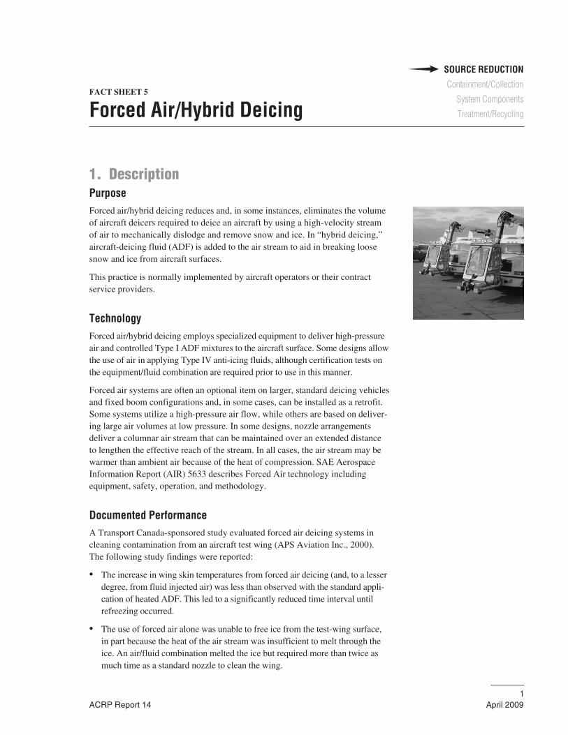
1. DescriptionPurposeForced air/hybrid deicing reduces and, in some instances, eliminates the volumeof aircraft deicers required to deice an aircraft by using a high-velocity streamof air to mechanically dislodge and remove snow and ice. In “hybrid deicing,”aircraft-deicing fluid (ADF) is added to the air stream to aid in breaking loosesnow and ice from aircraft surfaces.
This practice is normally implemented by aircraft operators or their contractservice providers.
TechnologyForced air/hybrid deicing employs specialized equipment to deliver high-pressureair and controlled Type I ADF mixtures to the aircraft surface. Some designs allowthe use of air in applying Type IV anti-icing fluids, although certification tests onthe equipment/fluid combination are required prior to use in this manner.
Forced air systems are often an optional item on larger, standard deicing vehiclesand fixed boom configurations and, in some cases, can be installed as a retrofit.Some systems utilize a high-pressure air flow, while others are based on deliver-ing large air volumes at low pressure. In some designs, nozzle arrangementsdeliver a columnar air stream that can be maintained over an extended distanceto lengthen the effective reach of the stream. In all cases, the air stream may bewarmer than ambient air because of the heat of compression. SAE AerospaceInformation Report (AIR) 5633 describes Forced Air technology includingequipment, safety, operation, and methodology.
Documented PerformanceA Transport Canada-sponsored study evaluated forced air deicing systems incleaning contamination from an aircraft test wing (APS Aviation Inc., 2000).The following study findings were reported:
• The increase in wing skin temperatures from forced air deicing (and, to a lesserdegree, from fluid injected air) was less than observed with the standard appli-cation of heated ADF. This led to a significantly reduced time interval untilrefreezing occurred.
• The use of forced air alone was unable to free ice from the test-wing surface,in part because the heat of the air stream was insufficient to melt through theice. An air/fluid combination melted the ice but required more than twice asmuch time as a standard nozzle to clean the wing.
ACRP Report 14 April 2009
SOURCE REDUCTION
Containment/Collection
System Components
Treatment/Recycling
1
• In tests to remove dry snow, the air/fluid combination and the standard fluidnozzle cleaned the test-wing in about the same time, but the air/fluid combi-nation used about 80 percent less fluid.
• The short time-to-refreeze following forced air deicing precludes its use as aone-step deicing process, and undermines its suitability as the first-step in atwo-step deicing process.
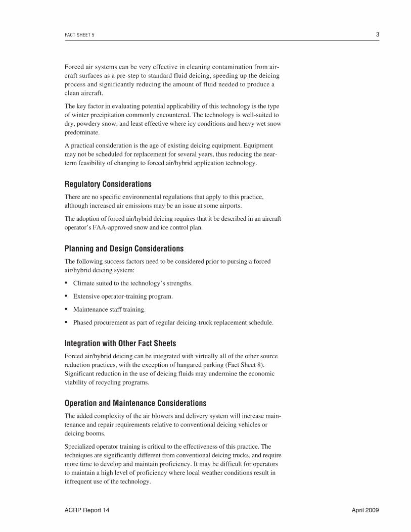
Reported experience indicates that performance in field operations is difficult toquantify with confidence and varies with the type of freezing precipitation. Thetechnology has been found to be most effective under dry/powdery snow conditionsand least effective in removing ice that has bonded to the aircraft surface. Table 1below summarizes reported glycol reduction from facilities where this technologywas found to be practicable. These results may be significantly better than whatcan be expected under less than ideal conditions. Reports on low effectiveness aregenerally not quantified, in part because interest in the technology disappearswhen it is found to not meet the aircraft operator’s needs.
2 FACT SHEET 5
April 2009 ACRP Report 14
Table 1. Percent Glycol Reduction by User Type
User Type Reduction Note
Aircraft operator 85 Predominantly ideal conditions
Contract operation 65 Midwestern airport with centralized deicing pads
Medium hub airport 46–67 Range reflects seasonal comparisons with varyingweather
Aircraft operators who have adopted this technology cite the following reasonsfor the decision:
• The time required to clean an aircraft of snow can be reduced under certainconditions by properly trained personnel.
• A significant reduction in ADF usage over conventional trucks is possibleunder certain types of weather conditions, such as dry snow and frost.
• The potential source reduction benefits of the technology can assist facilitiesand airports with maintaining compliance with stormwater regulations.
There may be additional operational efficiencies due to the decreased frequencyin refilling deicing fluid tanks.
2. Implementation ConsiderationsApplicability AssessmentForced air systems are not approved for use as a one-step deicing process, or forthe first step of a two-step deicing process unless the system has been tested andshown to be satisfactory. The SAE G12E Equipment Subcommittee has docu-mented a test procedure for this purpose.
Forced air systems can be very effective in cleaning contamination from air-craft surfaces as a pre-step to standard fluid deicing, speeding up the deicingprocess and significantly reducing the amount of fluid needed to produce aclean aircraft.
The key factor in evaluating potential applicability of this technology is the typeof winter precipitation commonly encountered. The technology is well-suited todry, powdery snow, and least effective where icy conditions and heavy wet snowpredominate.
A practical consideration is the age of existing deicing equipment. Equipmentmay not be scheduled for replacement for several years, thus reducing the near-term feasibility of changing to forced air/hybrid application technology.
Regulatory ConsiderationsThere are no specific environmental regulations that apply to this practice,although increased air emissions may be an issue at some airports.
The adoption of forced air/hybrid deicing requires that it be described in an aircraftoperator’s FAA-approved snow and ice control plan.
Planning and Design ConsiderationsThe following success factors need to be considered prior to pursing a forcedair/hybrid deicing system:
• Climate suited to the technology’s strengths.
• Extensive operator-training program.
• Maintenance staff training.
• Phased procurement as part of regular deicing-truck replacement schedule.
Integration with Other Fact SheetsForced air/hybrid deicing can be integrated with virtually all of the other sourcereduction practices, with the exception of hangared parking (Fact Sheet 8).Significant reduction in the use of deicing fluids may undermine the economicviability of recycling programs.
Operation and Maintenance ConsiderationsThe added complexity of the air blowers and delivery system will increase main-tenance and repair requirements relative to conventional deicing vehicles ordeicing booms.
Specialized operator training is critical to the effectiveness of this practice. Thetechniques are significantly different from conventional deicing trucks, and requiremore time to develop and maintain proficiency. It may be difficult for operatorsto maintain a high level of proficiency where local weather conditions result ininfrequent use of the technology.
FACT SHEET 5 3
ACRP Report 14 April 2009
Noise due to the high air stream velocity may necessitate hearing protection foroperators and for nearby ground service personnel.
If used to remove non-adhered cold dry snow, it is important to ensure that theair stream is cold enough to avoid melting of the snow. The surfaces must bechecked after cleaning to ensure that no snow has melted and refrozen, adheringto the wing.
Operational efficiencies may result due to increased time intervals between deic-ing fluid resupply, in particular for deicing vehicles/equipment with deicer fluidtanks. Similarly, operational efficiencies can be realized by using forced air sys-tems to remove accumulated snow versus physical/mechanical removal methods,and the opportunity for damage to the aircraft is minimized.
3. CostsCapital CostsThe initial capital investment for forced air/hybrid deicing is dependent on thecosts associated with the specialized equipment purchase. Anecdotal informationfrom users of this technology indicates that the incremental cost associated withthe forced air option on a deicing truck is in the neighborhood of $100,000,including a recommended enclosed cab feature.
Operations and Maintenance CostsAdditional maintenance costs may be expected because of the increased com-plexity of the machinery. Increased fuel consumption is required to operate theair blowers. However, aircraft operators have reported that overall the incremen-tal cost of this technology above conventional equipment may be recovered insavings from reduced deicer usage within several seasons. Additional savingsmay be achieved through reductions in departure delays.
ReferenceSAE G-12e Equipment Subcommittee. In progress. Forced Air or Forced
Air/Fluid Equipment for Removal of Frozen Contaminants. AerospaceInformation Report (AIR) 5633.
4 FACT SHEET 5
April 2009 ACRP Report 14

FACT SHEET 6
Infrared Deicing Technology
1. DescriptionPurposeThis practice utilizes infrared (IR) energy to melt frost, snow, and ice from thesurface of an aircraft, greatly reducing the need for deicing fluids. This is anemerging technology.
Responsibility for implementation and operation would be by a specialized servicecontractor in coordination with an airport.
TechnologyInfrared energy can be produced in many different ways, but the systems typicallyhave natural gas- or propane-fired emitters that are “tuned” to optimize the meltingof frost, ice, and snow. One manufacturer has developed a drive-through structurewith emitters where the aircraft is taken to be de-iced. Another manufacturer hasdeveloped a system, currently in the research and development phase, that placesthe emitters in large movable panels that can be mounted on stationary booms or atruck. The infrared energy applied to the aircraft does not heat the air, nor is it lostin the air before it hits the aircraft. The IR energy does not pass through the aircraftsurface and has a negligible effect on aircraft cabin temperature.
Some glycol use is still required for anti-icing after melting to provide holdovertime during periods of active freezing or frozen precipitation. Depending on thelocation of the system, some deicing of the aircraft may be necessary before itmoves toward the infrared space.
Documented PerformancePerformance data on infrared deicing facilities are limited by the number andscale of facilities in commercial operation to date. Reductions in glycol use of upto 70 to 90 percent per individual aircraft deicing have been reported. Becauseall existing installations serve a small fraction of the total aircraft traffic at theairports where they are located, there are no data available on airportwide glycoluse reductions.
Data are available for two facilities in the New York metropolitan area:
• Angelo (2006) reported an 80–90 percent reduction per aircraft in glycol useat the Newark airport with the system installed there.
• An infrared installation at JFK Airport was operated during the 2006–2007deicing season, which included two ice storms but was otherwise relativelymild. Glycol reductions of approximately 90 percent per aircraft were
ACRP Report 14 April 2009
SOURCE REDUCTION
Containment/Collection
System Components
Treatment/Recycling
1
Commercially operated infrareddeicing currently uses the “drive-through” concept.
Some glycol use is still requiredfor anti-icing after melting to provide holdover time duringperiods of active freezing orfrozen precipitation.

reported under snow and ice conditions. Defrosting operations were reportedas having used no glycol.
2. Implementation ConsiderationsApplicability AssessmentThe following factors should be considered in evaluating the potential applica-bility of this technology to a particular airport:
• The IR system provides aircraft deicing, but does not provide any holdovertime. Supplemental application of aircraft deicers or anti-icers is likely to berequired for safe flight operations.
• With the current drive-through designs, land requirements and siting of aninfrared facility are key determinants regarding basic feasibility. See“Regulatory Considerations” and “Planning and Design Considerations.”
• Substantial upfront infrastructure costs are associated with construction of aninfrared facility. In most cases, some level of commitment by aircraft opera-tors to use the facility would be required to prove the business case for a newinstallation.
• Some airports have been able to find productive uses (e.g., vehicle storageand maintenance) for the IR structures during the nondeicing season.
Regulatory ConsiderationsThe FAA has produced several guidance documents related to the use of IRenergy for deicing and encourages the development and use of this technology. IRfacilities need to meet the criteria of FAA AC 120-89, “Ground Deicing UsingInfrared Energy.” Use of IR energy for deicing can be approved as part of anyPart 121, 125, or 135 certificate holder’s deicing/anti-icing program or plan. FAApublication AC 150/5300-14 CHG 2 (“Change #2 to Design of Aircraft DeicingFacilities”) provides an appendix entitled “Design of Infra-Red Aircraft DeicingFacilities.”
Air emissions issues and applicable regulations should be considered with thispractice. Aircraft movement to the deicing facility may increase air emissions. Inaddition, the power generation and gas used by the infrared emitters may haveemissions ramifications. These issues need to be examined at the airport levelbefore a decision is made to employ this practice.
Planning and Design ConsiderationsThe location and design of the IR system structure is critical to its acceptance andsuccess. IR facility placement must take into consideration the aircraft launch areaand allow for adequate approach and egress. These facilities can be land intensive.The structure itself must conform to FAA Part 77 and be approved for tower sight-lines and runway object-free areas. Part 77 includes “imaginary surfaces” that
2 FACT SHEET 6
April 2009 ACRP Report 14

define navigable airspace with specific height and construction restrictions. Basicelectrical, water, and gas utilities are required.
The size and type of aircraft operating at the facility must be considered to deter-mine if they can be accommodated by the IR system. In most cases, it will beadvisable to consider a “composite” aircraft when designing an infrared deicingfacility. That is, consider the most constraining features of all of the variousaircraft that are envisioned using the facility.
A screening-level traffic analysis will provide an estimate of the number of facili-ties that would be required to serve a given portion or subset of an airport’s deicingneeds. If the airport operates with significant “pushes” each day where a largenumber of aircraft are departing during a relatively short period, an IR facility maypresent a bottleneck during severe weather conditions. Under these circumstances,conventional deicing of aircraft may be required to ensure adequate throughput.
FAA publication AC 150/5300-14 CHG 2 (“Change #2 to Design of AircraftDeicing Facilities”) provides standards and recommendations for the design andconstruction of infrared aircraft-deicing facilities. In 2005, the FAA issuedAdvisory Circular AC 120-89 (“Ground Deicing Using Infrared Energy”) to offerguidance to airlines on how to integrate infrared deicing operations into theiroperating plans.
Integration with Other Fact SheetsAs discussed earlier, some level of deicing or anti-icing will still need to be per-formed on aircraft under many conditions. Additional collection and containmentof the resulting glycol-laden runoff need to be provided at the IR deicing facility.This localized collection and containment would be a likely opportunity forcollection of high concentration of glycol.
Because this is a source control practice, its use will likely reduce the volume ofdeicing stormwater requiring collection and treatment, with reductions being pro-portional to the level of implementation at an airport. Glycol recovery operationsmay be negatively impacted if the volumes of high-concentration runoff arereduced below the level critical to economic feasibility.
Operation and Maintenance ConsiderationsOperation and maintenance of the IR facility are typically provided by a servicecontractor with specialized skills and training.
Ground traffic coordination may impose new operational requirements.
3. CostsAs with performance data, cost data are limited on the IR deicing facilitiesbecause of the few installations to date. The most recent implementations havebeen installed under cooperative agreements between the airport and the technology provider.
FACT SHEET 6 3
ACRP Report 14 April 2009
Capital CostsThe range of costs for construction of a single-bay deicing facility was reportedas $1 million to $4 million in 1997. The 68,644-ft2 facility at JFK is reported tohave cost $9.5 million. Final costs are dependent upon airport location and size,number of bays, and local geotechnical conditions.
Operations and Maintenance CostsOperating costs for infrared deicing have been cited as being significantly lowerthan conventional deicing with fluids.
ReferenceAngelo, W. F. 2006. New Deicing Technology May Save Groundwater.
Engineering News-Record. May 8.
4 FACT SHEET 6
April 2009 ACRP Report 14

FACT SHEET 7
Physical Removal
1. DescriptionPurposeThis practice provides the opportunity to reduce the volume of aircraft deicers usedin wintertime operations by physically (mechanically) removing snow or ice fromaircraft. Manual methods of snow removal are useful in certain circumstances andcan be used as long as safety is not compromised.
Physical removal techniques are the responsibility of the aircraft operator or itscontracted service provider.
TechnologyPhysical removal of snow or ice involves manual labor and brooms, ropes, andbrushes to remove accumulated snow from an aircraft. Hot-air-blast deicing sys-tems may also be used. This practice requires that care be taken to avoid damageto the aircraft during the process of physically removing snow and ice.
Typically, after snow or ice has been physically removed, deicing or anti-icingfluid will need to be applied to an aircraft to remove any remaining frozen con-tamination, and to provide adequate holdover time prior to its takeoff.
A description of devices and associated procedures available to remove contamina-tion is available in Transport Canada document TP 14052—Guidelines for AircraftGround-Icing Operations (http://www.tc.gc.ca/CivilAviation/publications/TP14052). This document describes the safe use of brooms, ropes, and scrap-ers, and touches on the use of portable forced-air-heaters to remove frost.
There is a separate set of technologies that serve to physically remove frozen pre-cipitation during flight. “Boot” deicing systems, often used on smaller propelleraircraft, employ inflatable pneumatic or hydraulic boots, installed on the leadingedge of aircraft wings, to crack and dislodge ice from the aircraft. Other mechani-cal means that have been evaluated on an experimental basis include electricalresistive heating on small aircraft (heating mats applied to the surface of the aircraft). These technologies have no impact on the use of deicing fluids.
Documented PerformanceThe performance of physical removal techniques is very site-specific, dependingon factors such as the type of precipitation and the aircraft fleet mix.
Anecdotal reports indicate that manual approaches to removing contaminationare effective in particular circumstances, such as pre-deicing removal of largeamounts of snow during early morning hours before operations start-up, and
ACRP Report 14 April 2009
SOURCE REDUCTION
Containment/Collection
System Components
Treatment/Recycling
1

removing small accumulations of dry cold non-adhered snow, thereby avoidingthe need for fluid deicing.
2. Implementation ConsiderationsApplicability AssessmentPhysical removal is most successful with loose precipitation (e.g., dry powderysnow) and smaller aircraft with horizontal surfaces that can be easily accessed byramp personnel. Larger aircraft and those with high wings present serious accessand safety issues that make physical removal impractical or unsafe. Protrudingsensors or antennae on the surface of an aircraft may also make physically remov-ing precipitation impractical.
Items that should be evaluated prior to considering physical removal techniquesinclude the size and configuration of the aircraft, the timeliness required prior todepartures, traffic volumes, availability of suitable personnel, and the frequencyof dry powdery snow.
Physical removal is more likely to be applicable at general aviation airports due tothe smaller size of the aircraft involved. Aircraft operators may consider thisprocess in conjunction with anti-icing protection to reduce the use of aircraft-deicing fluid.
Personnel performing mechanical deicing require training to ensure that they useproper equipment and methods to maintain safety and not damage the aircraft.
Regulatory ConsiderationsThe primary regulatory consideration for the implementation of the physical/mechanical removal practice is incorporation into the aircraft operator’s FAA-approved snow and ice control plans. Safety guidelines related to labor (exposureto the elements, working under slippery conditions, etc.) should also be considered.
Planning and Design ConsiderationsThe following factors should be considered in planning for physical removal:
• Frequency of snowfall that is subject to efficient physical removal.
• Size and configuration of aircraft.
• Staffing and labor requirements.
• Time requirements associated with physically removing snow or ice.
• Number of aircraft requiring the service at peak departure times.
• Suitable equipment to provide personnel with safe access to aircraft surfaces.
• Provision of training and equipment to avoid damage to highly sensitive andoften fragile sensors, antennas, vortex generators, and other aircraft surfacefeatures.
2 FACT SHEET 7
April 2009 ACRP Report 14

Integration with Other PracticesPhysical removal techniques may be employed prior to the application of aircraftdeicing or anti-icing fluids to reduce the total amount of fluid required. In thosecases, applicable practices (containment/collection, conveyance/storage, andtreatment/disposal practices) can be implemented to further reduce the dischargeof deicing agents into the stormwater system.
Operation and Maintenance ConsiderationsThe primary operational considerations are worker safety and ensuring that nodamage is incurred to the aircraft during the physical removal process.
Because manual methods of snow removal may be very time consuming, theirapplication must be compatible with flight departure schedules.
3. CostsThe equipment costs to accomplish manual removal of snow from aircraft is rela-tively modest and generally would be covered under operating costs. Equipmentpurchases would be limited to brooms, ropes, brushes, and access ladders. Laborcosts are the primary component of operation and maintenance costs.
FACT SHEET 7 3
ACRP Report 14 April 2009

FACT SHEET 8
Hangared Parking
1. DescriptionPurposeHangared parking seeks to reduce or eliminate the volume of aircraft deicersapplied by avoiding accumulation of snow or ice on the aircraft. This practice isnormally implemented by aircraft operators or their contract service providers.
TechnologyThe application of this practice does not rely on technology. Hangared parkingsimply avoids exposing an aircraft to snowfall, freezing rain, etc., until just priorto its departure. Anti-icing may still be required to protect the aircraft from snowor ice accumulated during taxiing from the hanger to takeoff.
Documented PerformanceThe net reduction in deicer usage that can be achieved through this practicevaries with climate, precipitation type, and characteristics of the aircraft opera-tions. During periods of winter precipitation, this practice requires the applica-tion of anti-icing fluids to an aircraft to avoid snow or ice accumulation prior tothe aircraft’s takeoff.
2. Implementation ConsiderationsApplicability AssessmentThe size of aircraft, the timeliness of departures, traffic volume, and the amountof suitable and available hangar space should be assessed prior to relying onhangared parking as an alternative to deicing operations. Where operations per-mit and adequate space is available, aircraft can be moved into hangars to warmup and melt off any freezing precipitation in advance of a scheduled departure.Generally, this practice is not suited to passenger or cargo operations whereaircraft are loaded outside.
Smaller general aviation airports are more likely to implement hangared-parkingalternatives due to the size of the aircraft involved. In addition, military installa-tions are more likely to have hangar space for aircraft, especially smaller fighters.
Regulatory ConsiderationsThe primary regulatory considerations concern FAA requirements and constraintson location and configuration of structures on the airfield.
ACRP Report 14 April 2009
SOURCE REDUCTION
Containment/Collection
System Components
Treatment/Recycling
1
Aircraft such as these F-16Fighting Falcons are protectedfrom the elements inside thehangar.
Smaller airports such as the FortCollins–Loveland MunicipalAirport can more easily implementthis practice due to costs and sizeof the hangar space.
Where significant taxiing to and from hangar locations is required, there may beregulatory concerns related to increased air emissions.
Planning and Design ConsiderationsThe following factors should be considered in hangared parking:
• Availability, location, and adequacy of existing hangar space.
• Aircraft size.
• Nature of aircraft operations.
• Loading operations (indoor or outdoor requirements).
• Space for and cost of new hangar construction.
Integration with Other PracticesNot applicable.
Operation and Maintenance ConsiderationsStandard hangar space operation and maintenance need to be considered for thispractice.
Operational considerations in utilizing hangared parking include the practicalityof ground movement of aircraft to and from the hangars. Long taxi distances willincrease fuel consumption and air emissions and potentially complicate airfieldground traffic management. It is also important to ensure that taxi routes aremaintained so hangared aircraft do not become stranded in an area that is not ahigh priority for being cleared of snow during storm events.
3. CostsAssuming hangared space is already available, there are few, if any, capitalcosts associated with implementing this practice. On the other hand, if hangarspace is required, the associated capital investment will be relatively high, alongwith traditional operations and maintenance costs. In most instances, it will becost-prohibitive to provide new hangar space for commercial aircraft.
Operating costs will vary with the specifics of the site. Reduced deicer usage willrepresent a reduction in operating costs, while additional labor required for mov-ing aircraft in and out of the hangar and increased fuel consumption will increaseoperating costs. Maintenance costs will be largely associated with maintenanceof the hangar and associated equipment.
2 FACT SHEET 8
April 2009 ACRP Report 14
FACT SHEET 9
Hot Water Deicing
1. DescriptionPurposeHot water deicing provides a specific opportunity to reduce or eliminate the vol-ume of aircraft deicers applied by using hot water for deicing operations in lieuof deicer agents.
Aircraft operators or their contract service providers are normally responsible forthe implementation of this practice.
TechnologyHot water deicing requires the appropriate technology to heat and distribute thewater at the prescribed temperature (at least 60°C, or 140°F). Normally, this canbe accomplished using conventional fixed or truck-mounted deicing equipment.
Hot water deicing is conducted as a two-step process: using a hot water spray toremove frozen material and then applying anti-icing fluid before the water has achance to freeze.
Documented PerformanceThe success of this practice varies widely based on the suitability of the climate,with factors such as ambient temperature and wind speeds affecting the perfor-mance. Because this practice by itself does not provide holdover protection, it isemployed as the first of a two-step process—being followed by the applicationof anti-icing fluids.
2. Implementation ConsiderationsApplicability AssessmentThe primary factor determining applicability of this practice is local weather dur-ing the deicing season. Under relatively mild winter weather conditions, it has beensuccessfully implemented by aircraft operators at a range of commercial airports.
Regulatory ConsiderationsThe requirements for conducting hot water deicing are described in SAE’s Aero-space Recommended Practice (ARP) 4737. The rules limit hot water deicing toambient air temperatures above −3°C (27°F), specify a minimum application tem-perature of at least 60°C (140°F), and require that it be followed by application ofan anti-icing fluid.
There are no environmental regulations that directly apply to this practice.
ACRP Report 14 April 2009
SOURCE REDUCTION
Containment/Collection
System Components
Treatment/Recycling
1

Planning and Design ConsiderationsThe primary planning consideration is practicality of aircraft operators adoptinghot water deicing under the ambient weather and operational conditions.
The procedures controlling the use of hot water must be very stringent becauseits application is dependent entirely on heat for protection against freezing. Forthis reason, this practice is recommended for use only at locations where there issupervision and dedicated deicing staff who are trained and proficient in its use.
Integration with Other PracticesPhysical removal techniques may be used prior to using hot water deicing. In addi-tion, practices associated with detecting the presence of snow or ice can be inte-grated with hot water deicing, such as aircraft ice detection sensors, enhancedweather forecasting, and ice detection and information systems. Forced air deicing(see Fact Sheet 5) may also be integrated with hot water deicing.
Because concentrations of glycol in runoff will be reduced with hot water deicing,this practice may undermine glycol recovery efforts (Fact Sheet 41).
Operation and Maintenance ConsiderationsBecause existing deicing equipment can be used for implementing hot waterdeicing, the primary consideration will be how to integrate using hot water intooverall deicing operations while ensuring safety and compliance with all FAArequirements.
Special care is needed to guard against the following operational risks:
• Decrease in ambient temperature below the accepted guideline during thedeicing activity.
• High wind conditions that quickly rob heat from the treated surface.
• Freezing of inadequately protected deicing equipment plumbing followingthe deicing activity.
• Inadequate labeling and checking of deicer tank contents, leading to misunder-standing of strength of fluid being applied.
• Dangerous icing of ramp surfaces in the absence of freeze point depressant.
3. CostsWhere existing deicing equipment can be used or adapted for use, capital invest-ment for hot water deicing would be negligible.
Cost savings from reduced deicing fluid use would be realized during operations.
2 FACT SHEET 9
April 2009 ACRP Report 14
FACT SHEET 10
Enclosed Deicing Bucket
1. DescriptionPurposeThis practice addresses the concept that equipment operators working in a com-fortable environment and protected from the elements will be more efficient intheir deicing usage and practices.
Aircraft operators or their contract service providers are normally responsible forthe implementation of this.
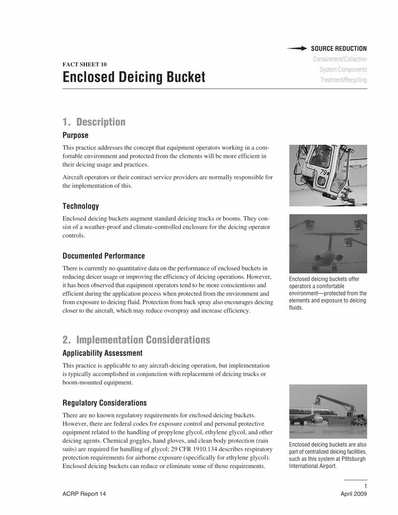
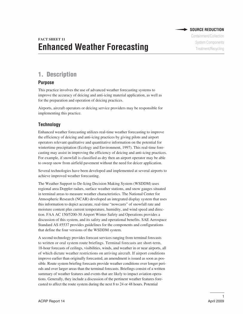
TechnologyEnclosed deicing buckets augment standard deicing trucks or booms. They con-sist of a weather-proof and climate-controlled enclosure for the deicing operatorcontrols.
Documented PerformanceThere is currently no quantitative data on the performance of enclosed buckets inreducing deicer usage or improving the efficiency of deicing operations. However,it has been observed that equipment operators tend to be more conscientious andefficient during the application process when protected from the environment andfrom exposure to deicing fluid. Protection from back spray also encourages deicingcloser to the aircraft, which may reduce overspray and increase efficiency.
2. Implementation ConsiderationsApplicability AssessmentThis practice is applicable to any aircraft-deicing operation, but implementationis typically accomplished in conjunction with replacement of deicing trucks orboom-mounted equipment.
Regulatory ConsiderationsThere are no known regulatory requirements for enclosed deicing buckets.However, there are federal codes for exposure control and personal protectiveequipment related to the handling of propylene glycol, ethylene glycol, and otherdeicing agents. Chemical goggles, hand gloves, and clean body protection (rainsuits) are required for handling of glycol; 29 CFR 1910.134 describes respiratoryprotection requirements for airborne exposure (specifically for ethylene glycol).Enclosed deicing buckets can reduce or eliminate some of those requirements.
ACRP Report 14 April 2009
SOURCE REDUCTION
Containment/Collection
System Components
Treatment/Recycling
1
Enclosed deicing buckets offeroperators a comfortable environment—protected from theelements and exposure to deicingfluids.
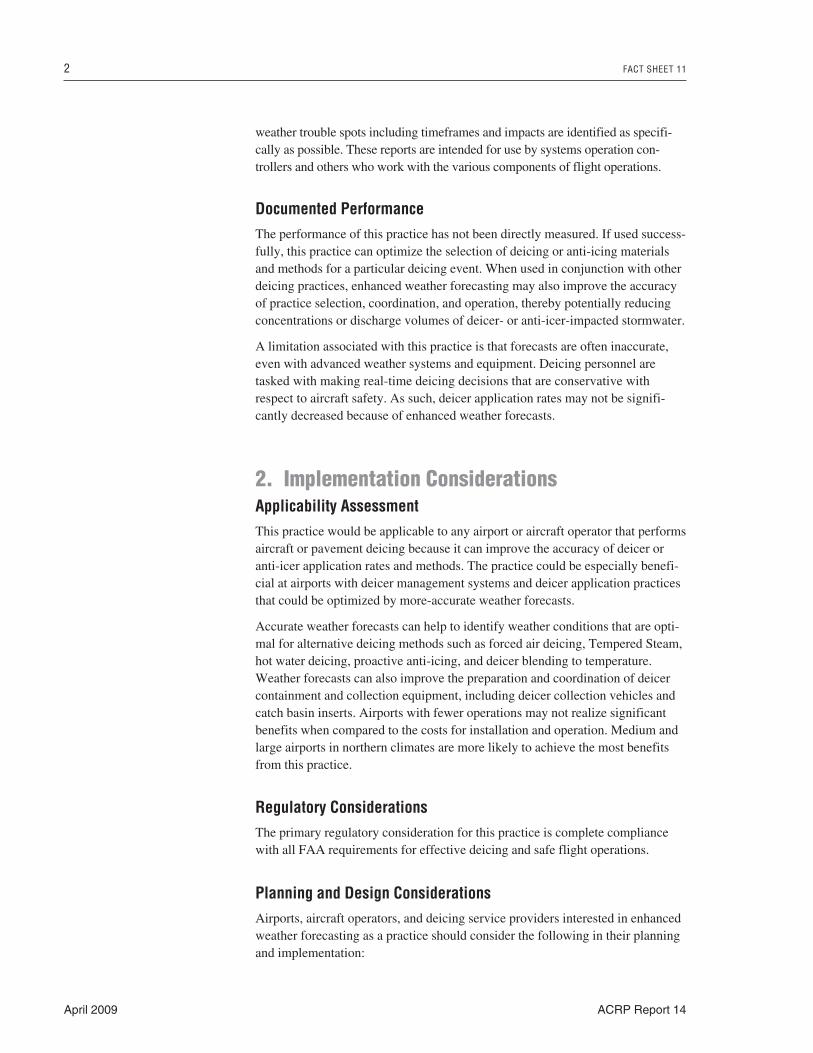
Enclosed deicing buckets are alsopart of centralized deicing facilities,such as this system at PittsburghInternational Airport.

Planning and Design ConsiderationsThe primary factor to be considered in planning for enclosed deicing buckets isprocurement of the equipment as part of regularly scheduled deicing vehiclereplacement.
Integration with Other PracticesEnclosed deicing buckets are compatible with other practices, and can be usedwith forced air deicing (see Fact Sheet 5), hot water deicing (Fact Sheet 9), andblending to temperature (Fact Sheet 4) source reduction practices.
Operation and Maintenance ConsiderationsThe operation and maintenance considerations for enclosed deicing buckets do notadd significantly to the standard operation and maintenance for deicing vehicles.
3. CostsMost deicing equipment manufacturers offer enclosed buckets as an optionalitem for deicing vehicles, which increases the initial capital investment.However, anecdotal evidence suggests that savings in deicing fluid usage frommore efficient application may offset this difference. The cost differencebetween open and enclosed buckets is demonstrated in the Table 1.
2 FACT SHEET 10
April 2009 ACRP Report 14
Enclosed deicing buckets areoffered as an option on variousdeicing vehicles.
Table 1. Typical Equipment Costs
Equipment $
Standard 2,200-gal 220,000open bucket deicing vehicle
Standard 2,200-gal 245,000enclosed bucket deicing vehicle
FACT SHEET 11
Enhanced Weather Forecasting
1. DescriptionPurposeThis practice involves the use of advanced weather forecasting systems toimprove the accuracy of deicing and anti-icing material application, as well asfor the preparation and operation of deicing practices.
Airports, aircraft operators or deicing service providers may be responsible forimplementing this practice.
TechnologyEnhanced weather forecasting utilizes real-time weather forecasting to improvethe efficiency of deicing and anti-icing practices by giving pilots and airportoperators relevant qualitative and quantitative information on the potential forwintertime precipitation (Ecology and Environment, 1997). This real-time fore-casting may assist in improving the efficiency of deicing and anti-icing practices.For example, if snowfall is classified as dry then an airport operator may be ableto sweep snow from airfield pavement without the need for deicer application.
Several technologies have been developed and implemented at several airports toachieve improved weather forecasting.
The Weather Support to De-Icing Decision Making System (WSDDM) usesregional area Doppler radars, surface weather stations, and snow gauges situatedin terminal areas to measure weather characteristics. The National Center forAtmospheric Research (NCAR) developed an integrated display system that usesthis information to depict accurate, real-time “nowcasts” of snowfall rate andmoisture content plus current temperature, humidity, and wind speed and direc-tion. FAA AC 150/5200-30 Airport Winter Safety and Operations provides adiscussion of this system, and its safety and operational benefits. SAE AerospaceStandard AS #5537 provides guidelines for the components and configurationsthat define the four versions of the WSDDM system.
A second technology provides forecast services ranging from terminal forecasts to written or oral system route briefings. Terminal forecasts are short-term, 18-hour forecasts of ceilings, visibilities, winds, and weather in or near airports, allof which dictate weather restrictions on arriving aircraft. If airport conditionsimprove earlier than originally forecasted, an amendment is issued as soon as pos-sible. Route system briefing forecasts provide weather conditions over longer peri-ods and over larger areas than the terminal forecasts. Briefings consist of a writtensummary of weather features and events that are likely to impact aviation opera-tions. Generally, they include a discussion of the pertinent weather features fore-casted to affect the route system during the next 8 to 24 or 48 hours. Potential
ACRP Report 14 April 2009
SOURCE REDUCTION
Containment/Collection
System Components
Treatment/Recycling
1
weather trouble spots including timeframes and impacts are identified as specifi-cally as possible. These reports are intended for use by systems operation con-trollers and others who work with the various components of flight operations.
Documented PerformanceThe performance of this practice has not been directly measured. If used success-fully, this practice can optimize the selection of deicing or anti-icing materialsand methods for a particular deicing event. When used in conjunction with otherdeicing practices, enhanced weather forecasting may also improve the accuracyof practice selection, coordination, and operation, thereby potentially reducingconcentrations or discharge volumes of deicer- or anti-icer-impacted stormwater.
A limitation associated with this practice is that forecasts are often inaccurate,even with advanced weather systems and equipment. Deicing personnel aretasked with making real-time deicing decisions that are conservative withrespect to aircraft safety. As such, deicer application rates may not be signifi-cantly decreased because of enhanced weather forecasts.
2. Implementation ConsiderationsApplicability AssessmentThis practice would be applicable to any airport or aircraft operator that performsaircraft or pavement deicing because it can improve the accuracy of deicer oranti-icer application rates and methods. The practice could be especially benefi-cial at airports with deicer management systems and deicer application practicesthat could be optimized by more-accurate weather forecasts.
Accurate weather forecasts can help to identify weather conditions that are opti-mal for alternative deicing methods such as forced air deicing, Tempered Steam,hot water deicing, proactive anti-icing, and deicer blending to temperature.Weather forecasts can also improve the preparation and coordination of deicercontainment and collection equipment, including deicer collection vehicles andcatch basin inserts. Airports with fewer operations may not realize significantbenefits when compared to the costs for installation and operation. Medium andlarge airports in northern climates are more likely to achieve the most benefitsfrom this practice.
Regulatory ConsiderationsThe primary regulatory consideration for this practice is complete compliancewith all FAA requirements for effective deicing and safe flight operations.
Planning and Design ConsiderationsAirports, aircraft operators, and deicing service providers interested in enhancedweather forecasting as a practice should consider the following in their planningand implementation:
2 FACT SHEET 11
April 2009 ACRP Report 14

• Identify the service or equipment that can provide enhanced weather-forecasting services that best meet the needs of the airport and aircraftoperators. Consider the following:
– Capital and operational cost for each service or equipment; and
– Types and accuracy of forecasts provided through each system and theirapplicability to existing airport deicing procedures and practices.
• Determine how enhanced weather forecasts will be incorporated into standardoperating procedures for deicing/anti-icing and deicer management.
• Develop protocol for identifying weather conditions that are appropriate forexisting deicer or anti-icer application methods and deicer managementpractices.
• Develop a training program for employees that will be using the weather-forecasting system.
Integration with Other PracticesThe success of many deicer application and deicer management practices may beenhanced by more-accurate and relevant weather forecasts. Enhanced weatherforecasts may enable an airport or aircraft operator to identify opportunities forusing alternative deicing practices, including alternative deicing materials andapplication equipment. Accurate weather forecasts can help to identify weatherconditions that are optimal for alternative deicing methods such as forced airdeicing (see Fact Sheet 5), tempered steam (Fact Sheet 15), hot-water deicing(Fact Sheet 9), proactive anti-icing (Fact Sheet 3), and deicer blending to temper-ature (Fact Sheet 4). Weather forecasts can also improve the preparation andcoordination of deicer containment and collection equipment, including deicercollection vehicles (Fact Sheet 23) and catch basin inserts (Fact Sheet 33).
Operation and Maintenance ConsiderationsOperational requirements associated with this practice depend on the technologyemployed. If a service provider is used, the primary operational issues will beincorporating the information into standard operating procedures and training ofpersonnel. If the technology is to be operated by the airport or aircraft operator,regular maintenance of equipment associated with sensors and forecasting tech-nologies will be required, as prescribed by the manufacturer.
3. CostsCosts associated with this practice consist of the costs of the weather-forecastingservice or system as well as the time for the airport/airline staff to interpret the data.
Capital CostsCapital costs include installation of specialized weather-forecasting equipmentonsite. Costs may be significant if the airport or aircraft operator chooses to own
FACT SHEET 11 3
ACRP Report 14 April 2009
!Even with enhanced weathersystems, forecasts aresometimes inaccurate.Consequently, deicing deci-sions that are conservativewith respect to aircraftsafety must be made.
and operate the instrumentation. Using a forecasting service will entail no capitalcosts if dedicated instrumentation is not required.
Operations and Maintenance CostsOperational costs associated may include costs associated with subscribing to oraccessing a specialized weather-forecasting service, or costs for maintenance ofonsite enhanced weather-forecasting sensors and equipment.
ReferenceEcology and Environment, I. 1997. Literature and Technology Review Report for
Aircraft and Airfield Deicing Waste Management, section 5, “TechnologyReview—Aircraft Deicing Waste Management.” Lancaster, NY.
4 FACT SHEET 11
April 2009 ACRP Report 14
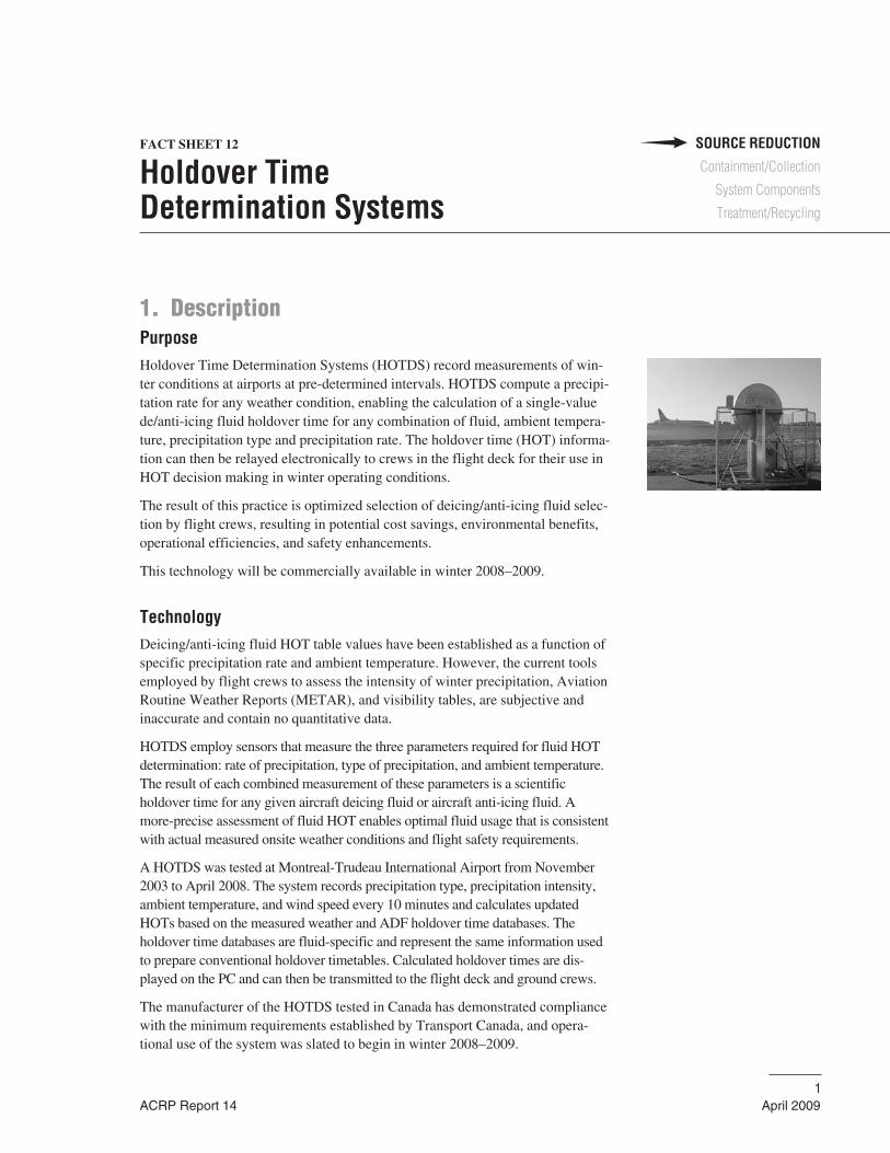
FACT SHEET 12
Holdover Time Determination Systems
1. DescriptionPurposeHoldover Time Determination Systems (HOTDS) record measurements of win-ter conditions at airports at pre-determined intervals. HOTDS compute a precipi-tation rate for any weather condition, enabling the calculation of a single-valuede/anti-icing fluid holdover time for any combination of fluid, ambient tempera-ture, precipitation type and precipitation rate. The holdover time (HOT) informa-tion can then be relayed electronically to crews in the flight deck for their use inHOT decision making in winter operating conditions.
The result of this practice is optimized selection of deicing/anti-icing fluid selec-tion by flight crews, resulting in potential cost savings, environmental benefits,operational efficiencies, and safety enhancements.
This technology will be commercially available in winter 2008–2009.
TechnologyDeicing/anti-icing fluid HOT table values have been established as a function ofspecific precipitation rate and ambient temperature. However, the current toolsemployed by flight crews to assess the intensity of winter precipitation, AviationRoutine Weather Reports (METAR), and visibility tables, are subjective andinaccurate and contain no quantitative data.
HOTDS employ sensors that measure the three parameters required for fluid HOTdetermination: rate of precipitation, type of precipitation, and ambient temperature.The result of each combined measurement of these parameters is a scientificholdover time for any given aircraft deicing fluid or aircraft anti-icing fluid. Amore-precise assessment of fluid HOT enables optimal fluid usage that is consistentwith actual measured onsite weather conditions and flight safety requirements.
A HOTDS was tested at Montreal-Trudeau International Airport from November2003 to April 2008. The system records precipitation type, precipitation intensity,ambient temperature, and wind speed every 10 minutes and calculates updatedHOTs based on the measured weather and ADF holdover time databases. Theholdover time databases are fluid-specific and represent the same information usedto prepare conventional holdover timetables. Calculated holdover times are dis-played on the PC and can then be transmitted to the flight deck and ground crews.
The manufacturer of the HOTDS tested in Canada has demonstrated compliancewith the minimum requirements established by Transport Canada, and opera-tional use of the system was slated to begin in winter 2008–2009.
ACRP Report 14 April 2009
SOURCE REDUCTION
Containment/Collection
System Components
Treatment/Recycling
1
Other HOTDS products, including a liquid water equivalent system developedby the National Center for Atmospheric Research, are currently in the develop-ment phase. The data collection intervals, sensor arrays and specifics of the pro-gramming associated with these products may differ from the ones presentedherein, but the system outputs are similar and serve the same objectives.
Documented PerformanceA HOTDS was tested at Montreal-Trudeau International Airport over five winterseasons. Over 2500 data points were collected with the system during this periodin nearly 100 natural precipitation events, spanning the full range of ambienttemperatures and precipitation types. Data from the HOTDS were compared todata collected using historical rate measurement procedures and human weatherobservations, and the correlation was excellent. In summer 2008, the HOTDSdemonstrated compliance with the Minimum Performance Specifications andQuality Assurance Requirements established by Transport Canada for use ofHOTDS outputs in Canadian air operations (see later section on RegulatoryConsiderations).
An operational assessment of the HOTDS was also performed at Montreal-Trudeau International Airport from 2004 to 2006. The objective of this work wasto compare actual flight crew decisions in winter operating conditions to optimalfluid decisions that would be made if HOTDS were available. The results indi-cated that flight crews selected to employ thickened Type IV fluids in conditionsthat did not warrant their use in 27 percent of all departures. An additional 4% ofall departures took off with exceeded HOTs.
2. Implementation ConsiderationsApplicability AssessmentThe potential cost savings, environmental benefits, operational efficiencies andsafety enhancements associated with this practice make it potentially applicableto most airports and aircraft operators subjected to winter precipitation condi-tions and the use of fluid holdover timetables.
The benefits associated with the implementation of this practice will vary largelyby the size of the operation, and therefore the capital and operating costs of thispractice may limit its practical use to medium- and large-size airports andoperations characterized by severe winter weather.
Regulatory ConsiderationsTransport Canada and the FAA develop and publish the deicing/anti-icing fluidHOT tables on an annual basis, and both organizations regulate the usage of theinformation by air carriers in their respective countries. The shift to automatedgeneration of deicing/anti-icing fluid HOT data will therefore require regulatoryoversight and approval.
2 FACT SHEET 12
April 2009 ACRP Report 14

In December 2007, Transport Canada issued regulatory approval for use ofHOTDS in Canadian air operations. As part of the regulatory approval process,Transport Canada developed Minimum Performance Specifications andMinimum Quality Assurance Requirements for HOTDS. A HOTDS manufac-turer must demonstrate adherence to the minimum requirements prior to beingapproved by Transport Canada.
The FAA is currently examining the development and adoption of a regulatoryapproval process for HOTDS.
Planning and Design ConsiderationsThe following planning and design considerations need to be examined whenimplementing this practice:
• Airport siting of the HOTDS so that the system will provide outputs that arerepresentative of conditions experienced by aircraft on the airfield.
• Determination of the desired data provision cycle time, which may affect thenumber of HOTDS systems that are ultimately required.
• Space requirements for the physical installation of the system hardware.
• Development of data communication pathways for system information (datalink, radio frequencies, wireless modems, etc).
Integration with Other PracticesHOTDS technology has the potential to be integrated with most practices,including all fluid-related practices. The combination of real-time weathermeasurement from the HOTDS and enhanced weather forecasting tools may beextremely useful to airports and aircraft operators.
Operation and Maintenance ConsiderationsOperational and maintenance requirements associated with this practice are notyet available because it has not been implemented at an operational level ortested over the long term.
Some operational considerations, such as how the HOT information from thesystem will be employed by flight crews, will need to be examined in detail. Thedevelopment of training programs for flight crews to ensure the transition frompaper tables to electronic information is essential, as well as the need for calibra-tion, maintenance and verification programs for the HOTDS hardware, to ensurethe validity of the system outputs.
3. CostsOverall costs associated with this practice are not yet fully defined, as thetechnology has yet to be fully implemented in an operational environment.
FACT SHEET 12 3
ACRP Report 14 April 2009

Capital CostsCapital costs for this practice are not fully defined, but are likely to consist primarilyof costs of the installation, the location, as well as the hardware and software.Alternatively, capital costs of the installation may be incurred by a service providerwho will sell the service to the airport/aircraft carrier community.
Operations and Maintenance CostsOperational costs will be uncertain until the technology has been fully commercial-ized but are likely to include costs for personnel to oversee system operation andmonitor results as well as costs for maintaining and testing the weather-monitoringequipment.
4 FACT SHEET 12
April 2009 ACRP Report 14
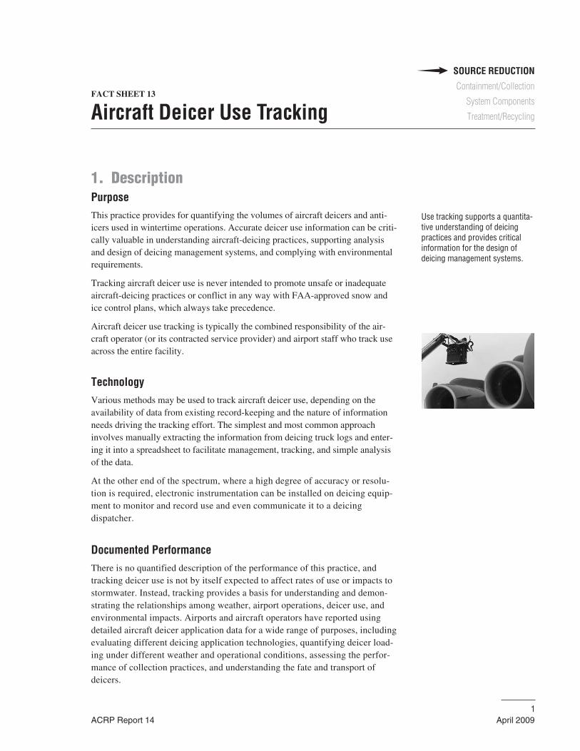
FACT SHEET 13
Aircraft Deicer Use Tracking
1. DescriptionPurposeThis practice provides for quantifying the volumes of aircraft deicers and anti-icers used in wintertime operations. Accurate deicer use information can be criti-cally valuable in understanding aircraft-deicing practices, supporting analysisand design of deicing management systems, and complying with environmentalrequirements.
Tracking aircraft deicer use is never intended to promote unsafe or inadequateaircraft-deicing practices or conflict in any way with FAA-approved snow andice control plans, which always take precedence.
Aircraft deicer use tracking is typically the combined responsibility of the air-craft operator (or its contracted service provider) and airport staff who track useacross the entire facility.
TechnologyVarious methods may be used to track aircraft deicer use, depending on theavailability of data from existing record-keeping and the nature of informationneeds driving the tracking effort. The simplest and most common approachinvolves manually extracting the information from deicing truck logs and enter-ing it into a spreadsheet to facilitate management, tracking, and simple analysisof the data.
At the other end of the spectrum, where a high degree of accuracy or resolu-tion is required, electronic instrumentation can be installed on deicing equip-ment to monitor and record use and even communicate it to a deicingdispatcher.
Documented PerformanceThere is no quantified description of the performance of this practice, andtracking deicer use is not by itself expected to affect rates of use or impacts tostormwater. Instead, tracking provides a basis for understanding and demon-strating the relationships among weather, airport operations, deicer use, andenvironmental impacts. Airports and aircraft operators have reported usingdetailed aircraft deicer application data for a wide range of purposes, includingevaluating different deicing application technologies, quantifying deicer load-ing under different weather and operational conditions, assessing the perfor-mance of collection practices, and understanding the fate and transport ofdeicers.
ACRP Report 14 April 2009
SOURCE REDUCTION
Containment/Collection
System Components
Treatment/Recycling
1
Use tracking supports a quantita-tive understanding of deicingpractices and provides criticalinformation for the design ofdeicing management systems.
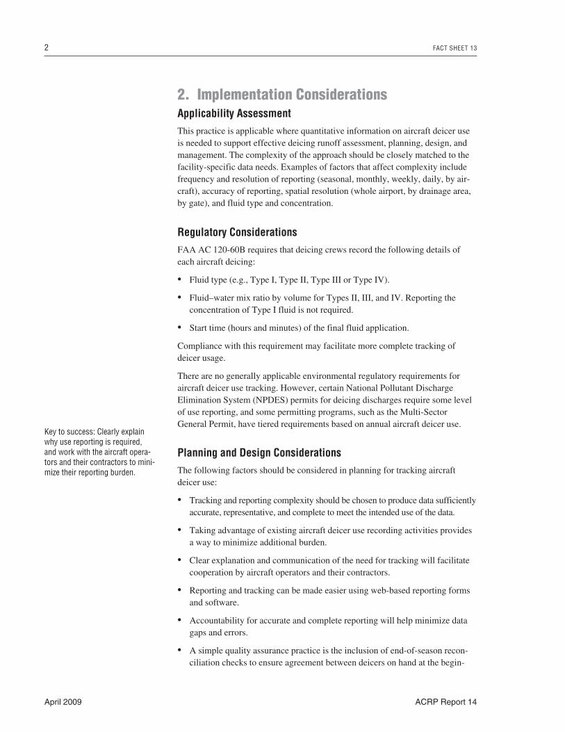
2. Implementation ConsiderationsApplicability AssessmentThis practice is applicable where quantitative information on aircraft deicer useis needed to support effective deicing runoff assessment, planning, design, andmanagement. The complexity of the approach should be closely matched to thefacility-specific data needs. Examples of factors that affect complexity includefrequency and resolution of reporting (seasonal, monthly, weekly, daily, by air-craft), accuracy of reporting, spatial resolution (whole airport, by drainage area,by gate), and fluid type and concentration.
Regulatory ConsiderationsFAA AC 120-60B requires that deicing crews record the following details ofeach aircraft deicing:
• Fluid type (e.g., Type I, Type II, Type III or Type IV).
• Fluid–water mix ratio by volume for Types II, III, and IV. Reporting theconcentration of Type I fluid is not required.
• Start time (hours and minutes) of the final fluid application.
Compliance with this requirement may facilitate more complete tracking ofdeicer usage.
There are no generally applicable environmental regulatory requirements foraircraft deicer use tracking. However, certain National Pollutant DischargeElimination System (NPDES) permits for deicing discharges require some levelof use reporting, and some permitting programs, such as the Multi-SectorGeneral Permit, have tiered requirements based on annual aircraft deicer use.
Planning and Design ConsiderationsThe following factors should be considered in planning for tracking aircraftdeicer use:
• Tracking and reporting complexity should be chosen to produce data sufficientlyaccurate, representative, and complete to meet the intended use of the data.
• Taking advantage of existing aircraft deicer use recording activities providesa way to minimize additional burden.
• Clear explanation and communication of the need for tracking will facilitatecooperation by aircraft operators and their contractors.
• Reporting and tracking can be made easier using web-based reporting formsand software.
• Accountability for accurate and complete reporting will help minimize datagaps and errors.
• A simple quality assurance practice is the inclusion of end-of-season recon-ciliation checks to ensure agreement between deicers on hand at the begin-
2 FACT SHEET 13
April 2009 ACRP Report 14
Key to success: Clearly explainwhy use reporting is required,and work with the aircraft opera-tors and their contractors to mini-mize their reporting burden.

ning of the season, purchased during the season, reported used, and on handat the conclusion of the season.
Integration with Other PracticesAircraft deicer use tracking can support the implementation, performance assess-ment, and refinement of a wide range of other practices.
Operation and Maintenance ConsiderationsOperational requirements associated with tracking aircraft deicer use are relatedto the methods of record-keeping and reporting. Primary considerations includethe following:
• Employing commonly used software for data entry, management, and analysis.
• Building the tracking and reporting system around practices already inplace—for example, compliance reporting required by FAA AC 120-60B.
• Minimizing data entry steps.
• Automating quality assurance checks.
Maintenance requirements consist of managing the database and generatingtracking reports. In those rare instances where electronic tracking instrumenta-tion is employed, some level of routine maintenance of that equipment should beexpected.
3. CostsThe primary costs will be associated with both aircraft operator and airport stafftime required for reporting and tracking activities. The magnitude of this effortwill be a function of the incremental effort beyond that required by existing AC120-60B reporting activities, the number of reporting entities, the complexity ofthe data being reported, and the types of data analyses and summary reportingrequired.
Capital costs for electronic instrumentation to measure, record, and report aircraftdeicer use can be substantial. The Air Transport Association estimated a cost of$11,000 per deicing truck for a comprehensive instrumentation package thatincludes a flowmeter, GPS positioning, outside air temperature sensor, nozzlesensor, and inline refractometer.
FACT SHEET 13 3
ACRP Report 14 April 2009

FACT SHEET 14
Aircraft Reduced Operations
1. DescriptionPurposeThis practice involves reducing or eliminating deicer usage by curtailing flightoperations during winter precipitation events. Reduced aircraft operations are theresponsibility of aircraft operators.
TechnologyThere is no technology involved in this practice.
Documented PerformanceThere is no documented quantitative information on the performance of reducedaircraft operations in reducing deicer usage or deicing runoff discharges. However,reductions in both usage and discharges would be reasonably expected withreduced operations.
2. Implementation ConsiderationsApplicability AssessmentReducing flight operations to reduce deicer usage and runoff has very limitedapplicability. In the general aviation and corporate flight communities, flight oper-ations are flexible and flights are often delayed or cancelled to avoid flying in win-ter weather. Certain military aircraft operations are also discretionary, and may bescheduled around the weather.
This practice is impractical for any aircraft that operate on set flight schedules,operate on demand, or involve emergency services.
Regulatory ConsiderationsWhere applicable, there are no regulatory considerations involved in reducedflight operations.
Planning and Design ConsiderationsThe following factors should be considered in planning for reduced operations:
• Relative contribution of anticipated reduction in deicing to improved environ-mental compliance.
ACRP Report 14 April 2009
SOURCE REDUCTION
Containment/Collection
System Components
Treatment/Recycling
1
Reducing flight operations toreduce deicer usage is not applicable to commercial airports.
• Flexibility of flight operations.
• Acceptance by aircraft operators.
• Loss in revenue or other economic impacts from reduced flight operations.
Integration with Other PracticesThis practice can be integrated with other deicing practices. Where reducedflight operations are feasible and result in reduced deicer usage, this practiceshould reduce requirements for collecting, storing, and treating deicing runoff.
Operation and Maintenance ConsiderationsNot applicable.
3. CostsCosts will be associated with lost revenues or other lost opportunities associatedwith delayed or cancelled flights.
2 FACT SHEET 14
April 2009 ACRP Report 14
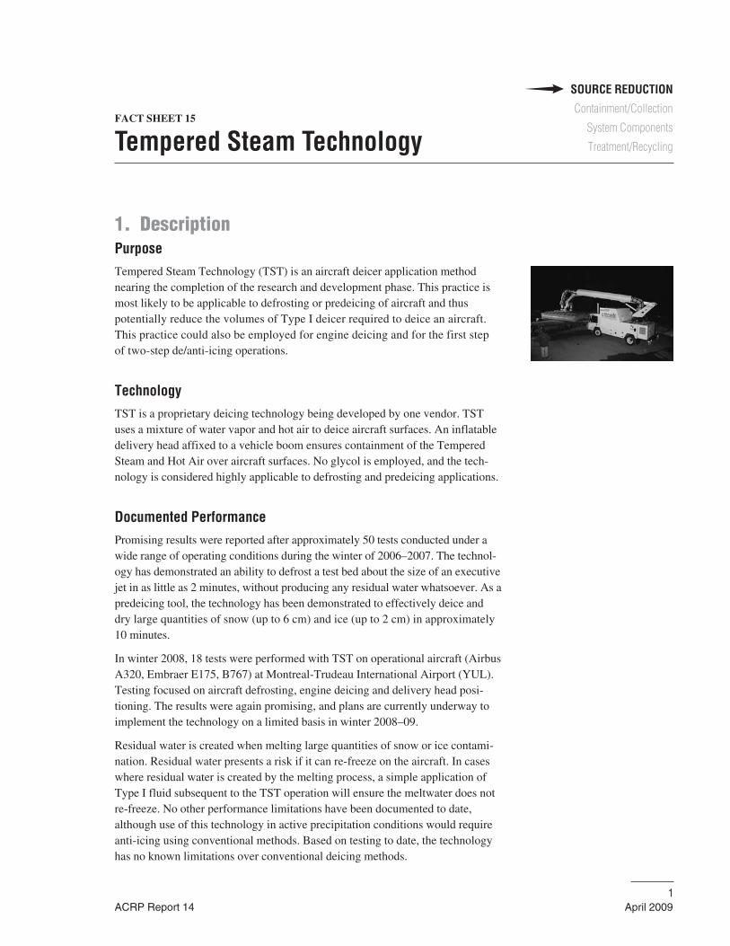
FACT SHEET 15
Tempered Steam Technology
1. DescriptionPurposeTempered Steam Technology (TST) is an aircraft deicer application methodnearing the completion of the research and development phase. This practice ismost likely to be applicable to defrosting or predeicing of aircraft and thuspotentially reduce the volumes of Type I deicer required to deice an aircraft.This practice could also be employed for engine deicing and for the first stepof two-step de/anti-icing operations.
TechnologyTST is a proprietary deicing technology being developed by one vendor. TSTuses a mixture of water vapor and hot air to deice aircraft surfaces. An inflatabledelivery head affixed to a vehicle boom ensures containment of the TemperedSteam and Hot Air over aircraft surfaces. No glycol is employed, and the tech-nology is considered highly applicable to defrosting and predeicing applications.
Documented PerformancePromising results were reported after approximately 50 tests conducted under awide range of operating conditions during the winter of 2006–2007. The technol-ogy has demonstrated an ability to defrost a test bed about the size of an executivejet in as little as 2 minutes, without producing any residual water whatsoever. As apredeicing tool, the technology has been demonstrated to effectively deice anddry large quantities of snow (up to 6 cm) and ice (up to 2 cm) in approximately10 minutes.
In winter 2008, 18 tests were performed with TST on operational aircraft (AirbusA320, Embraer E175, B767) at Montreal-Trudeau International Airport (YUL).Testing focused on aircraft defrosting, engine deicing and delivery head posi-tioning. The results were again promising, and plans are currently underway toimplement the technology on a limited basis in winter 2008–09.
Residual water is created when melting large quantities of snow or ice contami-nation. Residual water presents a risk if it can re-freeze on the aircraft. In caseswhere residual water is created by the melting process, a simple application ofType I fluid subsequent to the TST operation will ensure the meltwater does notre-freeze. No other performance limitations have been documented to date,although use of this technology in active precipitation conditions would requireanti-icing using conventional methods. Based on testing to date, the technologyhas no known limitations over conventional deicing methods.
ACRP Report 14 April 2009
SOURCE REDUCTION
Containment/Collection
System Components
Treatment/Recycling
1
2. Implementation ConsiderationsApplicability AssessmentThis practice would be most applicable to frost and predeicing applications in allclimates. It could also be employed for engine deicing and for all deicing opera-tions as a first step in two–step de/anti-icing. Anti-icing operations would requirethe use of glycol-based fluids. Airports that have limitations on glycol use at gatepositions or airports that have a large number of frost deicing events may be mostsuitable for TST.
The system may be employed at the gate, remote pads, or in centralized deicingoperations.
Regulatory ConsiderationsThe primary regulatory consideration associated with TST would be its accep-tance by regulators as an approvable component of an aircraft operator’s snowand ice control plan.
Planning and Design ConsiderationsAlthough TST is not yet commercially available, it is likely to be implemented ona limited basis in winter 2008–2009. Aircraft operators and FBOs that are inter-ested in TST as a practice should consider testing the technology once it is avail-able, to evaluate the technology’s effectiveness under their operational conditions.Success of the technology at a particular airport will require that it be adopted byFBOs and air carriers. Because the technology is vehicle-mounted, infrastructureplanning and design considerations applicable to this practice are minimal.
Integration with Other PracticesTST may be combined with nearly all other practices. The success of TST fordefrosting or predeicing may be aided with additional practices that help to char-acterize when weather conditions will be appropriate for use of the practice.
Operation and Maintenance ConsiderationsBecause the technology is still under development and has yet to be fully imple-mented into airport operations, the operating and maintenance requirements ofthe practice are not fully known at this point.
3. CostsThe practice is not yet commercially available at this time, and so definitivecosts have not yet been established. It is believed that the technology costs willbe less than those associated with conventional deicing, especially when the costbenefits (glycol savings, operational efficiencies, aircraft fuel savings, environ-mental savings) associated with the technology are considered.
2 FACT SHEET 15
April 2009 ACRP Report 14

FACT SHEET 16
Airfield Pavement–Deicing Product Selection
1. DescriptionPurposeThis fact sheet considers opportunities to employ alternative pavement-deicingproducts that have a reduced environmental impact, primarily in terms of bio-chemical oxygen demand (BOD) and aquatic toxicity found in the freeze pointdepressants (and in very few cases, the aquatic toxicity associated with addi-tives) required to meet certification specifications.
Product selection is typically the responsibility of airports and their contractors.
TechnologyPrior to 1990, glycols and urea were the primary airfield pavement deicers usedat airports. Since then, alternative pavement-deicing products that have lowerBODs and no issues with ammonia toxicity or nutrient enrichment have beenintroduced to the market. These new products are available in both solid andliquid forms.
Potassium acetate is supplied as liquid and can be applied either alone or as awetting agent in conjunction with granular deicing materials to improve efficiency.
Sodium acetate and sodium formate are supplied in granular and prill form.Generally, manufacturers recommend applying these materials with liquid pave-ment deicers to improve adherence to ice surface and prevent the solid materialsfrom being blown off the pavement. Granular products with irregular and sharpsurfaces may be less susceptible to drift by wind or jet blasts than prill products.
Ongoing research and development results in the continual improvement ofexisting products and the introduction of new products. These efforts are beingdriven by both environmental considerations and materials compatibility issues.
Documented PerformanceProduct selection offers the opportunity to reduce loadings of BOD and ammo-nia (and possibly toxicity although the research is ongoing) associated with air-field deicing while providing the necessary operational and safety performance.The most common example of success from this practice is found in numerousreports from airports where the replacement of urea with another certified air-field pavement deicer has eliminated problems with excessive ammonia concen-trations in stormwater discharges.
ACRP Report 14 April 2009
SOURCE REDUCTION
Containment/Collection
System Components
Treatment/Recycling
1
The primary environmental char-acteristics of potential concernare oxygen demand and toxicity.
Potassium formate liquid pave-ment deicer is used at some air-ports in northern Europe, but isnot currently used at any NorthAmerican airports.
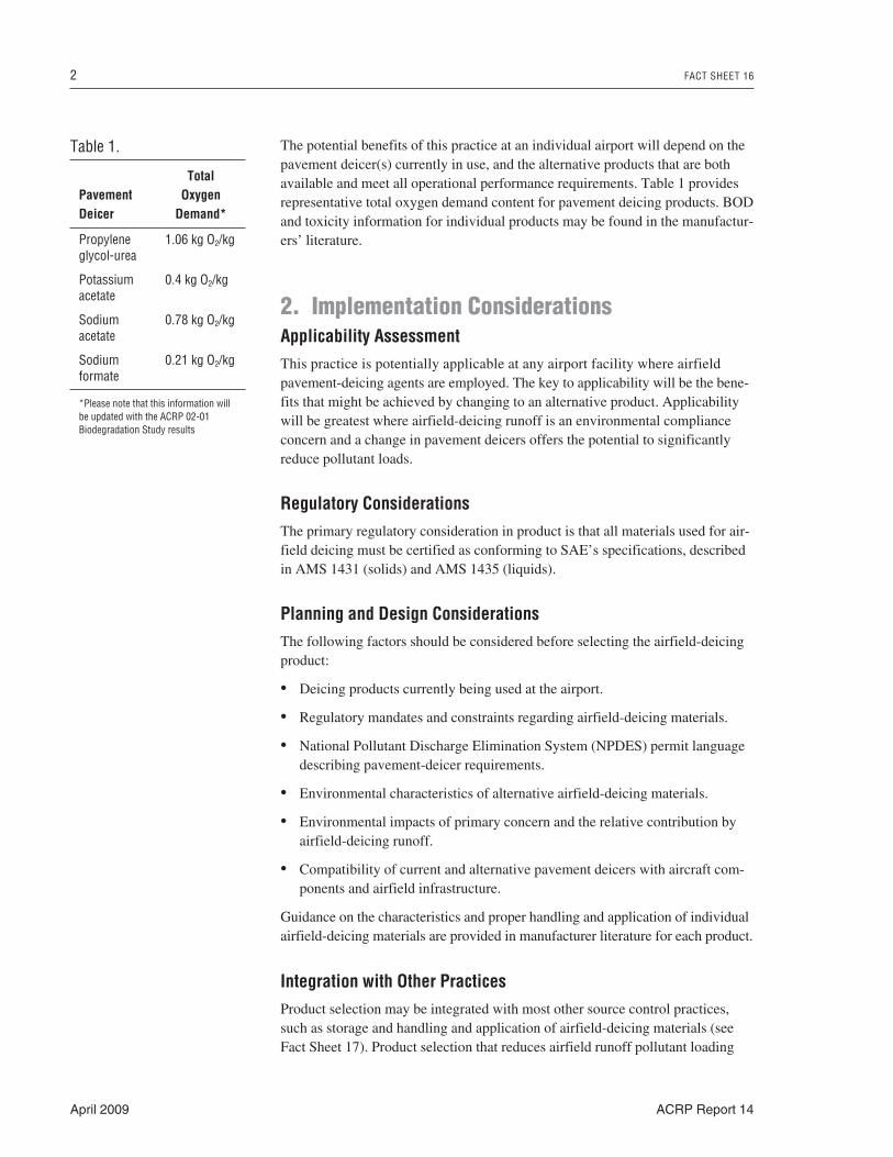
The potential benefits of this practice at an individual airport will depend on thepavement deicer(s) currently in use, and the alternative products that are bothavailable and meet all operational performance requirements. Table 1 providesrepresentative total oxygen demand content for pavement deicing products. BODand toxicity information for individual products may be found in the manufactur-ers’ literature.
2. Implementation ConsiderationsApplicability AssessmentThis practice is potentially applicable at any airport facility where airfieldpavement-deicing agents are employed. The key to applicability will be the bene-fits that might be achieved by changing to an alternative product. Applicabilitywill be greatest where airfield-deicing runoff is an environmental complianceconcern and a change in pavement deicers offers the potential to significantlyreduce pollutant loads.
Regulatory ConsiderationsThe primary regulatory consideration in product is that all materials used for air-field deicing must be certified as conforming to SAE’s specifications, describedin AMS 1431 (solids) and AMS 1435 (liquids).
Planning and Design ConsiderationsThe following factors should be considered before selecting the airfield-deicingproduct:
• Deicing products currently being used at the airport.
• Regulatory mandates and constraints regarding airfield-deicing materials.
• National Pollutant Discharge Elimination System (NPDES) permit languagedescribing pavement-deicer requirements.
• Environmental characteristics of alternative airfield-deicing materials.
• Environmental impacts of primary concern and the relative contribution byairfield-deicing runoff.
• Compatibility of current and alternative pavement deicers with aircraft com-ponents and airfield infrastructure.
Guidance on the characteristics and proper handling and application of individualairfield-deicing materials are provided in manufacturer literature for each product.
Integration with Other PracticesProduct selection may be integrated with most other source control practices,such as storage and handling and application of airfield-deicing materials (seeFact Sheet 17). Product selection that reduces airfield runoff pollutant loading
2 FACT SHEET 16
April 2009 ACRP Report 14
Table 1.
Total Pavement Oxygen Deicer Demand*
Propylene 1.06 kg O2/kgglycol-urea
Potassium 0.4 kg O2/kgacetate
Sodium 0.78 kg O2/kgacetate
Sodium 0.21 kg O2/kgformate
*Please note that this information will be updated with the ACRP 02-01Biodegradation Study results
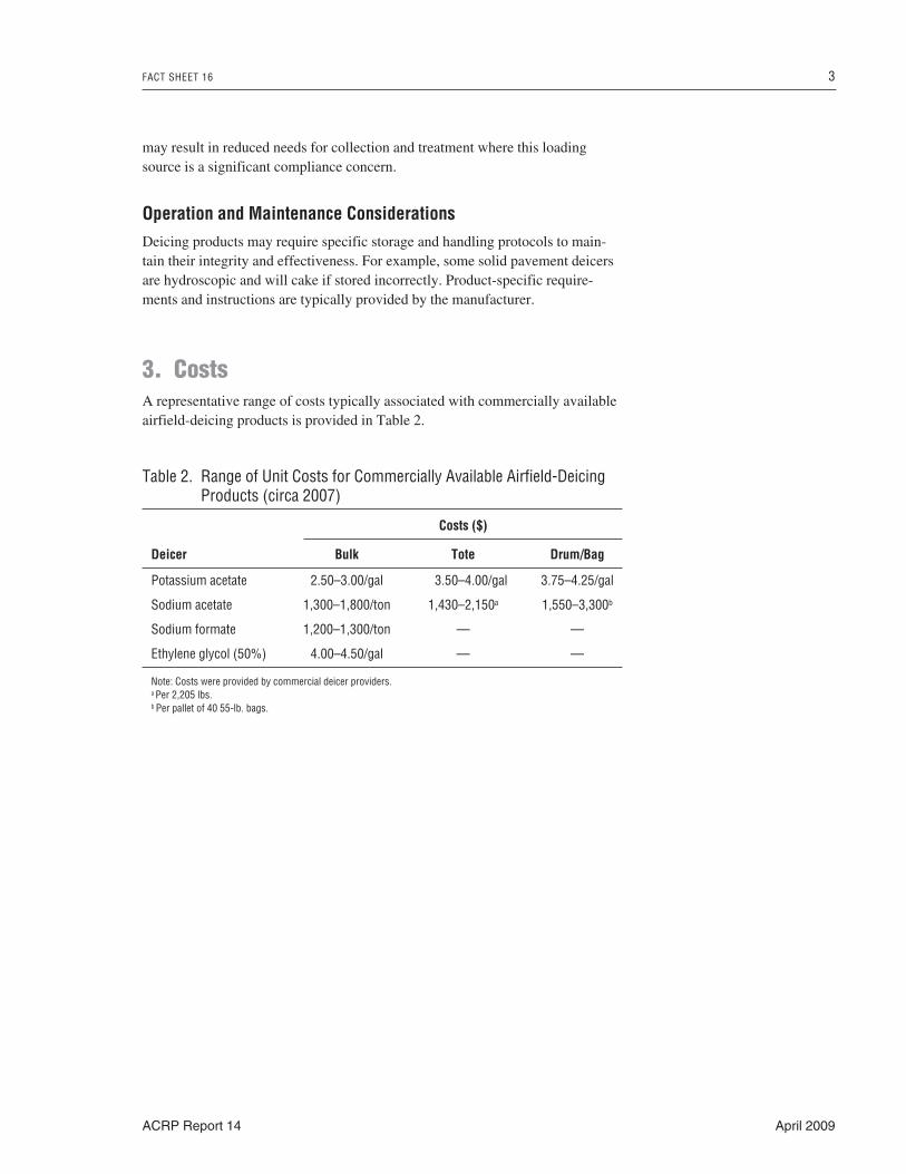
may result in reduced needs for collection and treatment where this loadingsource is a significant compliance concern.
Operation and Maintenance ConsiderationsDeicing products may require specific storage and handling protocols to main-tain their integrity and effectiveness. For example, some solid pavement deicersare hydroscopic and will cake if stored incorrectly. Product-specific require-ments and instructions are typically provided by the manufacturer.
3. CostsA representative range of costs typically associated with commercially availableairfield-deicing products is provided in Table 2.
FACT SHEET 16 3
ACRP Report 14 April 2009
Table 2. Range of Unit Costs for Commercially Available Airfield-DeicingProducts (circa 2007)
Costs ($)
Deicer Bulk Tote Drum/Bag
Potassium acetate 2.50–3.00/gal 3.50–4.00/gal 3.75–4.25/gal
Sodium acetate 1,300–1,800/ton 1,430–2,150a 1,550–3,300b
Sodium formate 1,200–1,300/ton — —
Ethylene glycol (50%) 4.00–4.50/gal — —
Note: Costs were provided by commercial deicer providers.a Per 2,205 lbs.b Per pallet of 40 55-lb. bags.

FACT SHEET 17
Storing and Handling of AirfieldDeicing/Anti-Icing Agents
1. DescriptionPurposeThis practice provides a means of preventing deicing and anti-icing agents fromcoming into contact with stormwater during their storage and handling prior tobeing applied.
Proper storage and handling of pavement deicing materials is normally theresponsibility of any member of the airport community who uses these products.
TechnologyGood housekeeping techniques, proper physical site usage, structural controls,regular maintenance, and the training of staff are typical activities related tostoring and handling pavement deicers.
To maintain the integrity and effectiveness of pavement deicing materials, theymust be stored, handled, and applied in a manner consistent with chemical-specific instructions provided by the manufacturer on the material safety datasheet (MSDS). Materials with reduced effectiveness may require larger appli-cation volumes or frequent reapplication, thus increasing the potential forstormwater pollution.
Documented PerformanceThere is no quantitative data available on the performance of this practice.Generally, benefits may be expected in terms of decreased deicer discharges tosurface water and potentially decreased deicing stormwater management costs.
The success of this practice at an individual airport can be evaluated by compar-ing pavement deicer consumption (rather than application) rates before and afterimplementing storage and handling practices. Any such comparison must, ofcourse, consider comparability of weather conditions.
2. Implementation ConsiderationsApplicability AssessmentThis practice is applicable to virtually any facility where airfield deicing materialsare stored or handled prior to application.
ACRP Report 14 April 2009
SOURCE REDUCTION
Containment/Collection
System Components
Treatment/Recycling
1
!Proper storage is importantto maintaining the integrityand effectiveness of pavement deicers.
Indoor storage and handling provides effective containment of solid pavement deicers.

Regulatory ConsiderationsGood housekeeping practices, including the proper storage and handling ofdeicing materials, are typically required under a National Pollutant DischargeElimination System (NPDES) industrial stormwater permit as an element of anairport’s Stormwater Pollution Prevention Plan.
Planning and Design ConsiderationsThe following factors should be considered in planning for storing and handlingairfield deicing/anti-icing agents:
• Specific NPDES permit language describing requirements.
• Volume of deicing/anti-icing materials to be stored.
• Packaging of the deicing products (e.g., bulk, super-sacks, totes, or tanks).
• Methods used for transferring deicing materials to the application vehicles.
• Opportunities to upgrade existing facilities or construct new facilities forimproved storage and handling.
• Indoor storage may offer an opportunity to incorporate heating of solid pave-ment deicers to enhance their effectiveness.
• Cost of storage and handling options.
Key approaches to storing and handling these products include the following:
• Store materials indoors or under cover, if possible.
• Store containers of material away from direct traffic routes to prevent acci-dental spills.
• Keep floors and ground surfaces clean and dry by using brooms, shovels,vacuum cleaners, or cleaning machines.
• Routinely inspect containers and tanks for leaks.
• Take actions to prevent stormwater run on to deicing/anti-icing materialstorage and handling areas. Block storm drains during material handlingoperations to prevent runoff of deicing/anti-icing materials.
• Provide a means of preventing spilled deicing materials from entering stormdrain inlets.
• Clean areas following deicing/anti-icing material transfers.
• Maintain adequate supplies of spill response equipment and materials inaccessible locations near operations.
• Emphasize the importance of these practices through personnel training.
• Restrict deicing material storage and handling to trained personnel only.
• Perform and document frequent inspections of storm drains, deicer applica-tion equipment, deicer runoff controls, and storage facilities; perform mainte-nance as required.
2 FACT SHEET 17
April 2009 ACRP Report 14
Your NPDES permit may havespecific requirements for storingand handling materials.

• Follow chemical-specific instructions and guidelines recommended by thematerial manufacturer to maintain the material’s integrity and effectiveness.
Integration with Other PracticesThis practice is compatible with all other deicing practices where pavement deic-ing materials are involved.
Operation and Maintenance ConsiderationsOperation and maintenance requirements related to materials’ storage and han-dling are normally part of a facility’s industrial NPDES compliance program.Deicing/anti-icing materials may require specific storage and handling protocolsto maintain their integrity and effectiveness. These product-specific instructionsare typically provided by the manufacturer. For example, solid materials requirestorage and handling that prevents clumping or dusting, either of which decreaseseffectiveness.
3. CostsCapital and operation and maintenance costs depend on the amount of deicermaterials to be stored and the locations and configurations of transfer areas. Highercosts will be incurred when covering or containing large loading/unloading areas isneeded.
FACT SHEET 17 3
ACRP Report 14 April 2009

FACT SHEET 18
Pavement Deicer MaterialsApplication Technology
1. DescriptionPurposeThis practice provides the opportunity to reduce the volume of pavement deic-ing materials (PDM) used in wintertime operations by facilitating efficient andoptimum application of PDM.
PDM application techniques are generally the responsibility of the airport operatoror its contracted service provider.
TechnologyThe simplest approach to efficient PDM application involves training and mainte-nance. Training airfield maintenance staff in appropriate techniques and applica-tion rates required to maintain safe operations and operators in the importance ofdisposing of excess deicers appropriately avoids unnecessarily exposing PDM tostormwater. Routine calibration and maintenance of PDM equipment ensures thatapplication rates are accurately set.
Enhanced weather-forecasting systems can also improve the efficiency of deicingpractices by airport operators. The quantitative information on the potential forfreezing precipitation can help determine appropriate PDM application.
An increasingly common technology is the use of onboard computers to controlapplication rates, with settings “locked out” of driver control to maintain consistentrates for the prevailing weather conditions.
One of the more advanced technologies for PDM application management inte-grates information from runway detection sensors and application vehicles. Allrunway clearing and deicing vehicles are equipped with GPS telemetry that trans-mits location and rate of runway deicer application to a central monitoring andlogging system. Airfield maintenance staff can monitor the vehicles’ operations,along with runway and air temperatures in real time, and the information is storedin the system. Monitoring data are used to decide how much additional deicing isrequired. Additional benefits of this technology include the ability to detect whenequipment is not operating to specifications (e.g., flow rates in booms, spreaders),providing in the event of an incident a detailed record of exactly where pavementdeicers were applied.
Documented PerformanceThe performance of PDM techniques is site-specific, depending on factors suchas the type of precipitation and the deicing mix. Up to 20 percent reduction in
ACRP Report 14 April 2009
SOURCE REDUCTION
Containment/Collection
System Components
Treatment/Recycling
1

pavement chemical use has been reported by the Munich International Airportwith the use of the most sophisticated telemetry and control systems (H. Pawlik,Flughafen München GMbH).
2. Implementation ConsiderationsApplicability AssessmentSophisticated PDM application technologies are more likely to be applicable atfacilities that regularly encounter ice and snow conditions and use significantquantities of PDM. The justification for this specialized equipment should beevaluated on a facility specific basis.
Personnel performing pavement deicing require training to ensure that they useproper equipment and methods to maintain safety. Training should also includetechniques for ensuring appropriate application rates and avoiding overuse orwaste.
Regulatory ConsiderationsThe primary regulatory consideration for the implementation of this practice is itsincorporation into an airport’s ice and snow control plan. Safety guidelines relatedto labor (exposure to the elements, working under slippery conditions, etc.) shouldalso be considered.
Planning ConsiderationsThe following factors should be considered in planning for efficient PDMapplication:
• Frequency of ice or snowfall that is subject to use of efficient pavement deic-ing techniques.
• Size and configuration of airfield.
• Staffing and labor requirements.
• Time requirements associated with removing snow or ice.
• Costs for deicing application technology.
Integration with Other PracticesMechanical methods, such as plows, brushes, blowers, and shovels for snowremoval may be employed prior to the application of PDMs to reduce the totalamount of fluid required.
Operation and Maintenance ConsiderationsThe Stormwater Pollution Prevention Plan (SWPPP) for the airport typicallyrequires the practicing for deicing/anti-icing practices. Generally, approaches for
2 FACT SHEET 18
April 2009 ACRP Report 14

inspection or training, operation considerations, and contingency responses areprovided.
Maintenance requirements vary with the type of equipment selected to use forpavement deicing application. Maintenance is either the responsibility of theairport operator or the contracted service operator.
3. CostsCapital CostsThe most advanced control systems have capital costs that include vehicle andairfield telemetry packages, along with a control system and associated soft-ware. Costs for a complete package at a medium to large airport can range from$500,000 to more than $1,000,000.
Operations and Maintenance CostsLabor and equipment maintenance costs are the primary components of opera-tion and maintenance costs and depend largely on facility-specific details.
Depending on the type of enhanced weather forecasting system employed,reported annual operating costs for small, medium, and large airports nationwidecan range from $2,400 to $8,400.
ReferenceThis was a personal communication with Mr. Pawlik who is with Flughafen
München GMbH (http://www.munich-airport.de/de/consumer/index.jsp).
FACT SHEET 18 3
ACRP Report 14 April 2009
FACT SHEET 19
Heated Pavement
1. DescriptionPurposeHeated pavement provides a means of deicing airfield pavement using electricalheating elements to minimize or eliminate the use of pavement deicing chemicals.
This practice is in the development stage. Implementation would be the responsi-bility of the airport.
TechnologyThe concept behind heated-pavement systems is that pavement surface tempera-tures are maintained above the freezing point of water, thus preventing accumu-lations of snow and ice from bonding with the pavement. Accomplishing thiscould facilitate the mechanical removal of frozen precipitation from paved areas,and could reduce the need for chemical deicing and anti-icing agents.
In the late 1990s, several manufacturers developed heated-pavement systemsthat could be applied to airfield pavement. Each of these took a differentapproach to the problem. One system consists of copper cables that are verti-cally embedded within a 2-inch-thick layer of conductive material installedbelow the paved surface. An electrical current passes through the conductivelayer and acts as the heat source to the copper cables. A second system usesheated pipes to maintain the pavement temperature. A completely differentapproach uses a 120,000-BTU truck-mounted heating panel to melt ice onpavement.
None of the respondents to EPA’s 2006 ELG questionnaire survey of more than150 airports reported using heated pavement as a best management practice.
Documented PerformanceVery limited documented information is available on any of these technolo-gies. A prototype of the electrically conductive pavement system was tested atChicago O’Hare International Airport in 1994 and 1995. Although the systemwas reported to have performed well at a testing level, it was also judgedexpensive to install and operate. There was no information available evaluatingthe potential cost savings from reduced use of airfield deicing agents using thispractice.
Testing of the portable heating panel system at a general aviation facility demon-strated the ability to melt ice layers as thick as 1.5 inches without damagingpaved surfaces or lighting.
ACRP Report 14 April 2009
SOURCE REDUCTION
Containment/Collection
System Components
Treatment/Recycling
1
There are no known operationalimplementations of any of theseapproaches.

2. Implementation ConsiderationsApplicability AssessmentBecause this technology is not commercialized, this practice is unlikely to beapplicable to airports at this time.
Regulatory ConsiderationsThe primary regulatory considerations for this technology would be acceptanceby FAA for installation and operation on an airfield.
Planning and Design ConsiderationsNot applicable at this time.
Integration with Other PracticesNot applicable at this time.
Operation and Maintenance ConsiderationsNot applicable at this time.
3. CostsNot applicable at this time.
2 FACT SHEET 19
April 2009 ACRP Report 14

FACT SHEET 20
Airfield Deicers—Physical Removal
1. DescriptionPurposeThis practice provides the opportunity to reduce the volume of airfield deicersused in wintertime operations by physically (mechanically) removing snow orice from the airfield in lieu of using deicing products for this purpose.
TechnologyPhysical removal of snow or ice involves using mechanized brooms and plows toremove accumulated snow from airfield pavement.
Under certain circumstances, especially in the case of dry snow, deicing productswill not need to be applied to the airfield after the snow has been physicallyremoved. Even when chemical deicing is needed after physical removal, less willbe required to achieve safe operating conditions than would otherwise be the case.
Documented PerformanceThe performance of physical removal techniques is very site-specific, dependingprimarily on the type of precipitation encountered.
2. Implementation ConsiderationsApplicability AssessmentPhysical removal is commonly conducted prior to application of pavement deicingproducts, and is widely applicable as a standard practice for airfield snow and iceremoval. It is most successful in reducing the need to apply deicing products whereloose dry precipitation, such as dry powdery snow, is involved.
Regulatory ConsiderationsThere are no environmental regulatory considerations associated with this practice.Implementation must be consistent with all applicable FAA policies and approvedairfield snow and ice control plans.
Planning and Design ConsiderationsAirports commonly employ physical removal procedures to make their use ofdeicing products more efficient. This fact sheet provides recognition that these
ACRP Report 14 April 2009
SOURCE REDUCTION
Containment/Collection
System Components
Treatment/Recycling
1

typical procedures reduce the amount of deicing fluids applied and can thereforebe considered as a source reduction practice.
Integration with Other PracticesPhysical removal techniques are commonly employed prior to the application ofdeicing products to reduce the total amount of product required.
Operation and Maintenance ConsiderationsThe primary operational consideration is ensuring aircraft safety.
3. CostsCapital costs for physical removal are limited to purchasing brooms and plows.Labor costs are the primary component of operation and maintenance costs.However, because these practices are typically performed at airports regardless,there are no “new” costs in considering this action as a practice.
2 FACT SHEET 20
April 2009 ACRP Report 14
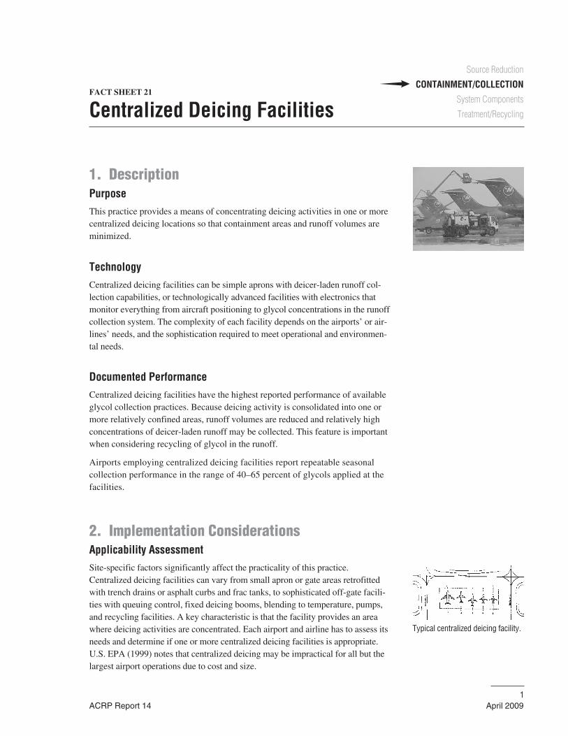
FACT SHEET 21
Centralized Deicing Facilities
1. DescriptionPurposeThis practice provides a means of concentrating deicing activities in one or morecentralized deicing locations so that containment areas and runoff volumes areminimized.
TechnologyCentralized deicing facilities can be simple aprons with deicer-laden runoff col-lection capabilities, or technologically advanced facilities with electronics thatmonitor everything from aircraft positioning to glycol concentrations in the runoffcollection system. The complexity of each facility depends on the airports’ or air-lines’ needs, and the sophistication required to meet operational and environmen-tal needs.
Documented PerformanceCentralized deicing facilities have the highest reported performance of availableglycol collection practices. Because deicing activity is consolidated into one ormore relatively confined areas, runoff volumes are reduced and relatively highconcentrations of deicer-laden runoff may be collected. This feature is importantwhen considering recycling of glycol in the runoff.
Airports employing centralized deicing facilities report repeatable seasonalcollection performance in the range of 40–65 percent of glycols applied at thefacilities.
2. Implementation ConsiderationsApplicability AssessmentSite-specific factors significantly affect the practicality of this practice.Centralized deicing facilities can vary from small apron or gate areas retrofittedwith trench drains or asphalt curbs and frac tanks, to sophisticated off-gate facili-ties with queuing control, fixed deicing booms, blending to temperature, pumps,and recycling facilities. A key characteristic is that the facility provides an areawhere deicing activities are concentrated. Each airport and airline has to assess itsneeds and determine if one or more centralized deicing facilities is appropriate.U.S. EPA (1999) notes that centralized deicing may be impractical for all but thelargest airport operations due to cost and size.
ACRP Report 14 April 2009
Source Reduction
CONTAINMENT/COLLECTION
System Components
Treatment/Recycling
1
Typical centralized deicing facility.

The following factors are considered in determining whether a centralizeddeicing facility is a potentially suitable practice:
• Operational considerations such as peak hour traffic flow, gate availability, air-craft size, typical weather conditions, etc., will present opportunities and con-straints. For example, it may not be economically feasible to construct a facilitylarge enough to accommodate a large number of aircraft launched during a rela-tively short departure window. Conversely, if the flow of arrivals and depar-tures is impeded by the availability of open gates, it may be beneficial to movedeicing operations to a centralized facility, potentially reducing delays.
• The amount of site preparation required to construct a centralized deicing facil-ity will affect cost. Large amounts of earthwork and drainage infrastructuremay make the initial capital investment too large to justify the benefits of acentralized facility.
• Site-specific issues such as available area, drainage infrastructure, prevailingwind conditions, and jet blast will determine if a centralized deicing facilitywill fit within the confines of the airfield.
• Centralized deicing facilities may be established on existing aprons or gate areasif the areas are already graded favorably for collecting and containing deicingrunoff. It may be feasible to deice smaller, regional jet–type aircraft at a central-ized deicing facility while continuing to allow larger aircraft to deice at the gate.
Regulatory ConsiderationsSiting requirements for centralized deicing facilities are outlined in FAAAdvisory Circular 150/5300-14. Centralized deicing facilities must also complywith the requirements of FAR Part 77, Objects Affecting Navigable Airspace,runway and taxiway safety area and object free area criteria, as well as TERPssurfaces such as precision obstacle free zones and W, X, and Y obstruction clear-ance surfaces. In accordance with FAA Environmental Handbook 5050.4A, acentralized deicing facility must not incorporate storage tanks or lagoons that mayattract waterfowl.
Typically, the driving factor in considering centralized deicing is compliance withstringent environmental regulatory requirements embodied in the airport’sNPDES permit. The decision to employ this practice to satisfy those requirementsis made through a site-specific evaluation of alternatives, rather than a specificrequirement for deicing pad technology as a compliance condition.
Planning and Design ConsiderationsFAA Advisory Circular AC 150-5300-14, “Design of Aircraft Deicing Facilities,”provides guidance in planning and designing centralized deicing facilities andremote aircraft deicing facilities. There are separate chapters on sizing and sitingthe deicing facilities, designing aircraft deicing pads, aircraft access and vehicleservice roads, and water quality mitigation.
The following factors should be weighed in planning and designing a centralizeddeicing facility:
2 FACT SHEET 21
April 2009 ACRP Report 14
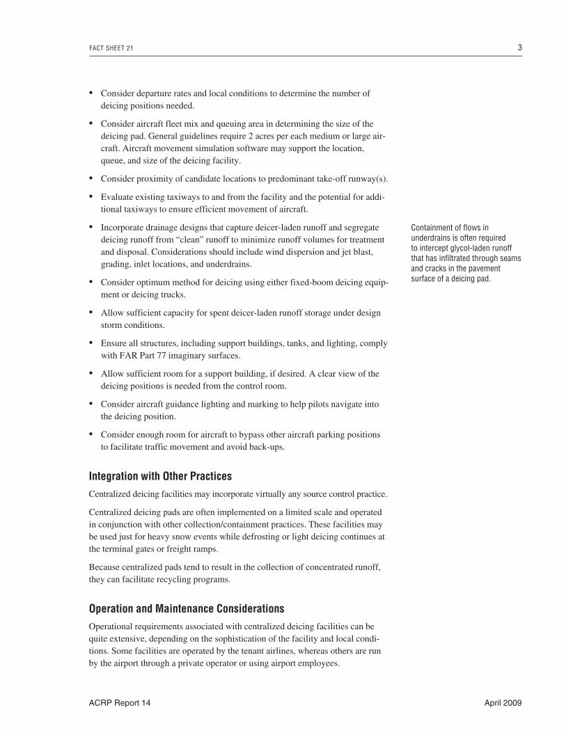
• Consider departure rates and local conditions to determine the number ofdeicing positions needed.
• Consider aircraft fleet mix and queuing area in determining the size of thedeicing pad. General guidelines require 2 acres per each medium or large air-craft. Aircraft movement simulation software may support the location,queue, and size of the deicing facility.
• Consider proximity of candidate locations to predominant take-off runway(s).
• Evaluate existing taxiways to and from the facility and the potential for addi-tional taxiways to ensure efficient movement of aircraft.
• Incorporate drainage designs that capture deicer-laden runoff and segregatedeicing runoff from “clean” runoff to minimize runoff volumes for treatmentand disposal. Considerations should include wind dispersion and jet blast,grading, inlet locations, and underdrains.
• Consider optimum method for deicing using either fixed-boom deicing equip-ment or deicing trucks.
• Allow sufficient capacity for spent deicer-laden runoff storage under designstorm conditions.
• Ensure all structures, including support buildings, tanks, and lighting, complywith FAR Part 77 imaginary surfaces.
• Allow sufficient room for a support building, if desired. A clear view of thedeicing positions is needed from the control room.
• Consider aircraft guidance lighting and marking to help pilots navigate intothe deicing position.
• Consider enough room for aircraft to bypass other aircraft parking positionsto facilitate traffic movement and avoid back-ups.
Integration with Other PracticesCentralized deicing facilities may incorporate virtually any source control practice.
Centralized deicing pads are often implemented on a limited scale and operatedin conjunction with other collection/containment practices. These facilities maybe used just for heavy snow events while defrosting or light deicing continues atthe terminal gates or freight ramps.
Because centralized pads tend to result in the collection of concentrated runoff,they can facilitate recycling programs.
Operation and Maintenance ConsiderationsOperational requirements associated with centralized deicing facilities can bequite extensive, depending on the sophistication of the facility and local condi-tions. Some facilities are operated by the tenant airlines, whereas others are runby the airport through a private operator or using airport employees.
FACT SHEET 21 3
ACRP Report 14 April 2009
Containment of flows in underdrains is often required to intercept glycol-laden runoffthat has infiltrated through seamsand cracks in the pavement surface of a deicing pad.

Maintenance requirements also vary with the degree of sophistication, but at aminimum include: annual maintenance of diversion valves and pumps, inspection/repair of pavement joints, and cleaning of the deicing runoff collection and storagesystem. Fixed booms are disassembled and serviced annually.
3. CostsCapital CostsDue to the high capital costs, centralized deicing facilities are generally impracticalfor all but the largest airports. The largest components of the capital costs includesite preparation and excavation, paving and drainage infrastructure, and contain-ment facilities. Additional costs include the deicing delivery method (fixed boomsor truck-mounted deicers), as well as the glycol delivery piping costs and costs fora building to house the mixing/blending equipment and the truck-mounted deicingvehicles. Representative reported capital costs for centralized deicing facilities areshown in Table 1. It should be noted that each facility is unique to the contextwithin which it is designed, and they are often constructed as part of larger airfieldprojects. It would be inadvisable to estimate costs for a new pad based on the datain the table.
Operations and Maintenance CostsReported operating costs for centralized deicing facilities are shown in Table 1.These costs typically include land and/or facility leases; labor; taxes; insuranceand overhead; electricity, water, and gas utilities; and potentially a surcharge feeto the airport for the applied fluid, similar to a fuel flowage fee.
4 FACT SHEET 21
April 2009 ACRP Report 14
Table 1. Examples of Capital and O&M Costs for Centralized Deicing Facilities
Airport Capital* ($M) Annual O&M* ($K)
Akron-Canton, OH 10 200
Atlanta, GA 8.1 80
Baltimore, MD 30 800
Cincinnati, OH 33 500
Cleveland, OH 45–50 3.5
Dallas-Forth Worth, TX 100 No data
Dayton, OH 23 300
Detroit, MI 80 1,500
Fairbanks, AK 5.75 15–20
Hartford, CT 34 500–600
Pittsburgh, PA 42 ∼ 700–1,100
*All costs are approximate.
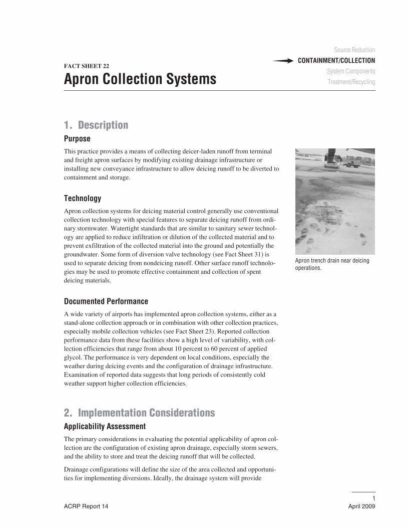
FACT SHEET 22
Apron Collection Systems
1. DescriptionPurposeThis practice provides a means of collecting deicer-laden runoff from terminaland freight apron surfaces by modifying existing drainage infrastructure orinstalling new conveyance infrastructure to allow deicing runoff to be diverted tocontainment and storage.
TechnologyApron collection systems for deicing material control generally use conventionalcollection technology with special features to separate deicing runoff from ordi-nary stormwater. Watertight standards that are similar to sanitary sewer technol-ogy are applied to reduce infiltration or dilution of the collected material and toprevent exfiltration of the collected material into the ground and potentially thegroundwater. Some form of diversion valve technology (see Fact Sheet 31) isused to separate deicing from nondeicing runoff. Other surface runoff technolo-gies may be used to promote effective containment and collection of spent deicing materials.
Documented PerformanceA wide variety of airports has implemented apron collection systems, either as astand-alone collection approach or in combination with other collection practices,especially mobile collection vehicles (see Fact Sheet 23). Reported collectionperformance data from these facilities show a high level of variability, with col-lection efficiencies that range from about 10 percent to 60 percent of applied glycol. The performance is very dependent on local conditions, especially theweather during deicing events and the configuration of drainage infrastructure.Examination of reported data suggests that long periods of consistently coldweather support higher collection efficiencies.
2. Implementation ConsiderationsApplicability AssessmentThe primary considerations in evaluating the potential applicability of apron col-lection are the configuration of existing apron drainage, especially storm sewers,and the ability to store and treat the deicing runoff that will be collected.
Drainage configurations will define the size of the area collected and opportuni-ties for implementing diversions. Ideally, the drainage system will provide
ACRP Report 14 April 2009
Source Reduction
CONTAINMENT/COLLECTION
System Components
Treatment/Recycling
1
Apron trench drain near deicingoperations.
opportunities to divert deicing runoff with minimal dilution from nondeicingareas through surface runoff or converging storm sewer lines. Apron renovationor new construction projects may offer opportunities to incorporate optimizedapron collection features, such as isolation of deicing drainage areas from non-deicing areas, placement of inlets close to deicing positions, and installation ofdiversions at optimal locations.
Because apron collection tends to involve larger areas of pavement thanmore-targeted collection practices, the volumes of deicing runoff collectedtend to be greater, and the concentrations of deicers in that runoff tend to belower. Adequate storage, coupled with a suitable treatment practice must beavailable for apron collection to be a practical option.
Regulatory ConsiderationsThe placement and configuration of apron drainage features must comply withFAA requirements for taxiways and aircraft aprons (FAA Advisory Circular150/5300-13, “Airport Design”). Apron drainage features must also comply withrunway and taxiway safety area and object-free-area criteria, as well as terminalinstrument procedure surfaces such as precision obstacle-free zones and W, X,and Y obstruction clearance surfaces.
Planning and Design ConsiderationsFAA Advisory Circular 150/5320-5C, “Surface Drainage Design,” provides gen-eral guidance in planning and designing apron collection systems. Separate sec-tions are included on sizing facilities and drainage and collection methods. Thegoal of the apron collection system for deicing runoff control is to maintain asmuch of the deicing runoff in the system as possible and reduce the loss ofmaterial to uncontrolled areas. The following factors should be considered inplanning and designing an apron collection system to achieve this goal:
• Consider the geometry of the system. For simple retrofits, look for nodeswhere diversions can be installed to isolate subdrainage networks that servethe deicing areas with minimal inflow from nondeicing areas. For majorapron renovation or new construction, a drain layout that reduces the surfacetravel distance for deicing runoff improves the potential for capture. Do notlocate the drain under the aircraft if fueling operations are planned for thedeicing position.
• For larger deicing areas, consider segmenting the surface drainage to minimizedilution during limited deicing operations.
• Consider slope and surface roughness to reduce the loss of fluid off the aproncontainment area due to jet blast.
• Seal pavement joints to reduce infiltration and deicing runoff loss through thepavement section.
• Consider service vehicle routes and taxi lanes when designing surface flowpaths to avoid tracking deicing runoff out of the collection system.
2 FACT SHEET 22
April 2009 ACRP Report 14
• Use single- or multiple-grate inlets for simple construction and low maintenance.
• Consider trench drains in low points when necessary to meet minimum sur-face grade requirements. Avoid using trench drains to create drainage divideson slopes.
• Require watertight inlets and drain structures and pipe penetrations.
• Require watertight pipe material and joints.
• Provide periodic trench flow check material to control subsurface flow inpipe bedding material.
• Provide underdrains for controlling deicing fluid and stormwater infiltrationand high groundwater. Allow diversion of the underdrains to the deicing fluidcollection system.
• Design the system using controls equipment that is suited to the systemobjectives and the capabilities of the operations staff.
Integration with Other PracticesApron collection systems can be implemented alone or in combination withother collection practices. Mobile collection vehicles (Fact Sheet 23) may beused to collect concentrated deicing runoff, to support recycling for example,with the apron collection system serving to contain the more dilute runoff. Aproncollection system features may be used in managing the melt-off from deicer-laden snow and in providing spill control capabilities.
Operation and Maintenance ConsiderationsOperational and maintenance requirements associated with an apron collectionsystem vary significantly depending on the sophistication of the system. Therequirements are significant in a system that includes pumping, diversion valves,monitoring, and storage in addition to conveyance to a treatment or recyclingprocess. In areas with winter weather that fluctuates between freezing precipita-tion and rainfall, manually operated systems will require a higher level of atten-tion and operation. A gravity flow system may have requirements as modest asperiodic observation and annual flushing.
Most apron collection system elements are underground and should be designedwith low maintenance in mind to avoid excavation, repair, and replacement costsand the costs of surface restoration and disruption of airfield operations.
Apron collection systems may be operated by the tenant airlines (for example, afreight apron operator, the dominant air carrier, or largest fixed base operator),or by the airport through a private operator or using their own employees. Eachfacility needs to consider the best method of operating the apron collection systemwith the interests of all users in mind.
Pavement joints on the apron surface need to be inspected annually. Any jointsshowing signs of defective sealant should be resealed, and any cracks in the
FACT SHEET 22 3
ACRP Report 14 April 2009

pavement should be sealed to reduce migration of the deicing runoff into thesubsurface drainage. Finally, storage tanks associated with the drainage systemshould be maintained and cleaned during the off-season to avoid odor andprevent corrosion or attack from residual deicing materials.
3. CostsCapital CostsThe capital costs for apron collection systems using existing infrastructure andsurface drainage techniques can be very low. Larger aprons require undergrounddrains and piping and may become significantly more costly. If mechanical con-trol and monitoring are required, the capital cost of conveyance facilities can beeven higher.
Operations and Maintenance CostsThough it may have a high capital cost, a large pipe gravity conveyance systemcan have nearly no operation and maintenance costs. Mechanical systems addsignificantly to the O&M costs because of the more complex nature of the facili-ties, the need for monitoring and data collection, and the ability to develop andimplement control strategies.
4 FACT SHEET 22
April 2009 ACRP Report 14

FACT SHEET 23
Glycol Collection Vehicles
1. DescriptionPurposeThis practice provides for active collection of aircraft deicing runoff from pave-ment surfaces using specialized vacuum-type collection vehicles.
TechnologyThese collection vehicles are commonly referred to by a variety of names,including sweeper-vacs, glycol recovery vehicles (GRVs), and “mobile collec-tion units.” Collection vehicles may be used for removing spent aircraft deicingfluid from the pavement virtually anywhere that aircraft are deiced and vehiclescan have access. Glycol collection vehicles are often used in conjunction withother, passive collection practices.
There are two basic design approaches in commercial glycol collection vehicles:truck chassis or trailer mounted. The truck chassis designs are adaptations of thestreet sweeper concept, with a vacuum unit, vacuum/sweeper head, and storagetank all mounted on a single self-propelled vehicle. Typically, a separate enginepowers the vacuum system. Trailer-mounted designs have the vacuum unit, col-lection head, and storage tank on a towed platform with power provided by eitheran engine mounted on the trailer chassis or a power take-off from the tow vehicle,typically a tractor.
Documented PerformanceGlycol collection vehicles can be operated to collect as much aircraft deicingrunoff as possible, or to just target the most concentrated runoff, depending onthe objectives of the collection program. Performance data on glycol collectionvehicle operations from several airports report glycol recovering between 23 and 53 percent of glycol applied in the collection area on an annual basis.The upper end of this reported range should be considered as reflecting optimalconditions.
The overall effectiveness of glycol collection vehicles varies based on thenumber of vehicles used relative to the areas and deicing activities served, andwhether they are used in conjunction with other collection methods, such asapron collection systems (see Fact Sheet 22), central deicing facilities (FactSheet 21), automated diversion valves (Fact Sheet 31), etc.
ACRP Report 14 April 2009
Source Reduction
CONTAINMENT/COLLECTION
System Components
Treatment/Recycling
1
Trailer-mounted collection unit
Truck chassis design
Glycol collection vehicles arecommonly referred to by a varietyof names, including “sweeper-vacs,” “glycol recovery vehicles”(GRVs), and “mobile collectionunits.”
2. Implementation ConsiderationsApplicability AssessmentVehicle-based glycol collection is generally well suited to situations where thefollowing conditions are present:
• Aircraft deicing is conducted at various locations around the airfield.
• Collection of relatively high-concentration runoff is desired.
• Catch basins and storm sewer inlets can be blocked to prevent deicing runofffrom entering the storm sewer prior to collection.
Other considerations include the following:
• Mobile glycol collection will increase the volume of vehicular traffic aroundgates and apron areas.
• Some temporary ponding of deicing runoff on the apron surface will occur.Coordination of collection operations will minimize the occurrence of thisponding.
• To the greatest extent possible, apron surfaces should be cleared of snow andheavy slush prior to mobile collection activities to avoid clogging themachinery. This can be a significant operational constraint on the effective-ness of this practice.
• Adequate staff must be available to operate the collection vehicles, open andclose the catch basin valves, and manage the collected runoff.
• It is essential to maintain close communication and coordination betweenthe glycol collection vehicle operators, aircraft deicing crews, and rampcoordinators.
Regulatory ConsiderationsThere are no direct regulatory considerations associated with operation of glycolcollection vehicles, other than compliance with all regulations regarding airsidevehicle operations.
At some facilities, there may be concerns over increased air emissions.
Planning and Design ConsiderationsGlycol collection vehicles work best where deicing runoff remains on the rampsurface and is accessible for collection. As such, the following must be consid-ered in developing an implementation plan:
• The capacity of the collection vehicle will be dictated by the amount of deicingfluid used at the facility during peak deicing events. Generally, larger capac-ity vehicles are more efficient, while smaller vehicles are able to operate inmore confined areas.
• Some method of blocking storm sewer inlets to keep deicing runoff on thesurface prior to its collection is essential to optimal performance. The most
2 FACT SHEET 23
April 2009 ACRP Report 14
reliable methods involve mechanical blocks installed within the inlets.Rubber mats may be used, but these are prone to being picked up by thecollection vehicle and displaced by jet blast and prop wash.
• Pavement surfaces and joints must be maintained in good conditionbecause the collection vehicle vacuum can suck up loose pavement andjoint material.
• Stations for transferring collected runoff from the collection vehicles to storageshould be located close to the collection areas to minimize transit distances.
• Solids collected with the deicing runoff must be managed and disposed ofappropriately.
• Provisions are required for efficient transfer of the collected runoff from thevehicle to storage. On-board pumps can be used to transfer runoff to above-ground tanks. An in-ground sump with a heavy grate can be used for rapidlyoffloading collection vehicles equipped with a dump body design.
• Collection vehicles are prone to clogging with snow and slush and requirea relatively clear surface for optimal effectiveness. Coordination withsnow removal operations and operator training will minimize the impacton collection operations.
Integration with Other PracticesGlycol collection vehicles may be combined with block-and-pump systems (FactSheet 24), apron collection (Fact Sheet 22), and centralized deicing pads (FactSheet 21). Often, this is done to target runoff from defrosting operations or tointercept high-concentration runoff. The relatively high concentrations that canbe collected facilitate reduced storage requirements and support recycling.
Operation and Maintenance ConsiderationsEffective operation of glycol collection vehicles requires trained staff and closecoordination with aircraft-deicing operations. Vehicle operators need to be avail-able at all times when aircraft deicing is conducted, and especially when heavyevents occur. Staffing of glycol collection vehicle programs can be by airport staffor use contractor personnel. Training and supervising operators is key to successwith this practice. Typically, a designated coordinator who tracks aircraft sched-ules and deicing operations, and directs the operations of the collection vehicleswill result in optimum performance.
The maintenance of the collection vehicles is similar to other ground-basedvehicles.
3. CostsCapital CostsGlycol collection vehicle costs depend on the type and capacity of vehicle.Purchase prices for purpose-built vehicles range between $85,000 and $350,000.
FACT SHEET 23 3
ACRP Report 14 April 2009
Dump feature enables rapidemptying of collected runoff
Some method of blocking stormsewer inlets to keep deicingrunoff on the surface prior to collection is essential to optimalperformance.
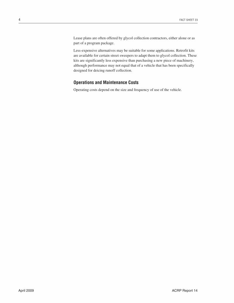
Lease plans are often offered by glycol collection contractors, either alone or aspart of a program package.
Less-expensive alternatives may be suitable for some applications. Retrofit kitsare available for certain street sweepers to adapt them to glycol collection. Thesekits are significantly less expensive than purchasing a new piece of machinery,although performance may not equal that of a vehicle that has been specificallydesigned for deicing runoff collection.
Operations and Maintenance CostsOperating costs depend on the size and frequency of use of the vehicle.
4 FACT SHEET 23
April 2009 ACRP Report 14
FACT SHEET 24
Block-and-Pump Systems
1. DescriptionPurposeThis practice provides a means of intercepting deicing stormwater near thesource. Implementation and operation of this practice is typically the respon-sibility of an airport, but tenants may consider implementation within theirleasehold.
TechnologyThe primary objective in employing block-and-pump systems is to interceptdeicing runoff close to the source, often using existing storm sewers for tempo-rary inline storage. This approach facilitates cost-efficient collection of runoffand can improve the economy of glycol treatment/recovery systems. Block-and-pump systems are often supplemented with glycol recovery vehicles (GRVs) tocollect a higher concentration deicing runoff.
Drainage blocks, consisting of valves (refer to Fact Sheet 31 Manual andAutomatic Diversion Valves) or inflatable sewer plugs, are installed withinthe drainage infrastructure to prevent concentrated deicing stormwater fromdischarging to surface water through the drainage system. Upstream of theblocking mechanism, detention is provided in the form of pipe storage, sur-face flooding, or storage within other drainage structures. Deicing stormwateris collected periodically using pumps or GRVs, and transported elsewhere for treatment or processing. Blocking mechanisms are generally opened orremoved during nondeicing periods to allow normal drainage of nonimpactedstormwater.
Documented PerformanceThe performance of a block-and-pump system for preventing the discharge ofdeicing stormwater depends upon the effective operation of the drainage blocksand collection of deicing stormwater during deicing events.
There are little available performance data specific to block-and-pump instal-lations, but the practice is popular among smaller airports. Twenty-one air-ports (15 percent of those surveyed) reported to EPA that they use such asystem. Of those airports reporting, all but seven were small-hub or non-hub-type airports.
ACRP Report 14 April 2009
Source Reduction
CONTAINMENT/COLLECTION
System Components
Treatment/Recycling
1
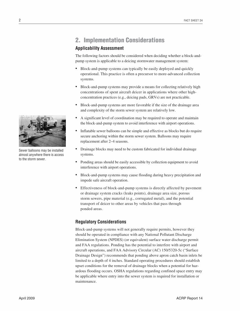
2. Implementation ConsiderationsApplicability AssessmentThe following factors should be considered when deciding whether a block-and-pump system is applicable to a deicing stormwater management system:
• Block-and-pump systems can typically be easily deployed and quicklyoperational. This practice is often a precursor to more-advanced collectionsystems.
• Block-and-pump systems may provide a means for collecting relatively highconcentrations of spent aircraft deicer in applications where other high-concentration practices (e.g., deicing pads, GRVs) are not practicable.
• Block-and-pump systems are more favorable if the size of the drainage areaand complexity of the storm sewer system are relatively low.
• A significant level of coordination may be required to operate and maintainthe block-and-pump system to avoid interference with airport operations.
• Inflatable sewer balloons can be simple and effective as blocks but do requiresecure anchoring within the storm sewer system. Balloons may requirereplacement after 2–4 seasons.
• Drainage blocks may need to be custom fabricated for individual drainagesystems.
• Ponding areas should be easily accessible by collection equipment to avoidinterference with airport operations.
• Block-and-pump systems may cause flooding during heavy precipitation andimpede safe aircraft operation.
• Effectiveness of block-and-pump systems is directly affected by pavementor drainage system cracks (leaks points), drainage area size, porous storm sewers, pipe material (e.g., corrugated metal), and the potentialtransport of deicer to other areas by vehicles that pass through ponded areas.
Regulatory ConsiderationsBlock-and-pump systems will not generally require permits, however theyshould be operated in compliance with any National Pollutant DischargeElimination System (NPDES) (or equivalent) surface water discharge permitand FAA regulations. Ponding has the potential to interfere with airport andaircraft operations, and FAA Advisory Circular (AC) 150/5320-5c (“SurfaceDrainage Design”) recommends that ponding above apron catch basin inlets belimited to a depth of 4 inches. Standard operating procedures should establishupset conditions for the removal of drainage blocks when a potential for haz-ardous flooding occurs. OSHA regulations regarding confined space entry maybe applicable where entry into the sewer system is required for installation ormaintenance.
2 FACT SHEET 24
April 2009 ACRP Report 14
Sewer balloons may be installedalmost anywhere there is accessto the storm sewer.

Planning and Design ConsiderationsThe following factors should be considered in planning to implement a block-and-pump system:
• Identify potential locations in the drainage system where blocks would bemost effective for capturing deicer runoff, and which would not cause signifi-cant upstream surface ponding or interference with airport operations.
• Develop standard procedures for preparing, inspecting, monitoring, operating,and maintaining the block-and-pump system, including upset conditions.
• Estimate time intervals and staffing required to operate, inspect, and maintainthe system during and between deicing events.
• The collection location should be accessible by recovery vehicles or vacuumtrucks, if applicable. The offloading location should be similarly convenient.
• This practice requires that joints or cracks in the pavement and within thedrainage infrastructure be sealed to prevent infiltration or exfiltration.Because storm sewers are typically not designed to be watertight, frequentpumping of collected stormwater will minimize losses to exfiltration. Theintegrity of the block-and-pump system can be directly examined throughregular visual inspections and/or tightness testing.
Integration with Other PracticesCommonly, a block-and-pump system is operated in conjunction with GRVs(see Fact Sheet 23) or a tanker truck with pumps, which collect the deicingstormwater that builds up behind the drainage block during deicing events.GRVs can also be used in conjunction with block and pump systems to collecthigher concentration runoff
Operation and Maintenance ConsiderationsOperational requirements associated with a block-and-pump system includethe manual operation of the drainage blocks, periodic testing of the pondedstormwater, pumping the collected deicing stormwater, and hauling it to stor-age and treatment. Maintenance tasks associated with block-and-pump sys-tems include regular inspections of the systems to ensure proper operation,removal of debris that may interfere with drainage block operation, repairs tomaintain watertight seals, and replacement of worn sewer balloons and valveparts.
3. CostsOverall costs associated with block-and-pump systems depend upon the type ofsystem employed, the number and size of drainage blocks required, the type ofcollection equipment selected, and the need for modifications to the existingdrainage system to maximize effectiveness.
FACT SHEET 24 3
ACRP Report 14 April 2009
Capital CostsCapital costs for block-and-pump systems may include drainage blocks, pumpsor other collection equipment, vehicles for transport, additional detention struc-tures, and modifications to the existing drainage infrastructure. Other initial costsmay include repairs to existing infrastructure and surrounding pavement toensure an adequate watertight seal.
Operations and Maintenance CostsOperational cost items for block-and-pump systems include labor associatedwith operating the blocking and collection mechanisms, transportation of col-lected fluid, and monitoring and analysis. At some airports sewer balloons areremoved at the end of each deicing season and reinstalled at the beginning ofthe next.
Maintenance costs may include the following:
• Repairs to seals within drainage infrastructure and surrounding pavement;
• Regular inspection of the block-and-pump system;
• Repairs to maintain proper system operation; and
• Periodic replacement of sewer balloons, if used.
4 FACT SHEET 24
April 2009 ACRP Report 14

FACT SHEET 25
Airfield Drainage Planning/Design/Retrofit
1. DescriptionPurposeThe primary purpose of airfield drainage design is to divert stormwater from air-field operations areas in order to provide a safe and stable surface for movementof aircraft and support equipment. A secondary purpose is to reduce stormwatercontaminants before they are discharged to the surface water system. For cold-weather airports, the most significant contaminant is uncollected spent deicingfluid. Considering the unique aspects of deicing runoff in the airfield drainagedesign process can improve overall control efforts.
TechnologyMost existing airfield drainage systems benefit from some passive control ofdeicing materials in stormwater. Mass balance monitoring at various airportsshows significant losses of deicers between point of application and stormwaterdischarge, and published research demonstrates that substantial biodegradationoccurs on apron surfaces, even at low temperatures (Revitt and Worrall, 2003).Degradation of deicers in runoff can be enhanced by applying basic stormwatermanagement principles, such as increasing the time that the materials remain inthe system and controlling the conveyance surfaces that the deicing contami-nants are exposed to. Systems that maintain drainage on the ground surface andmaximize contact with vegetation and soil are expected to get the greatestremoval benefit, while systems that promote rapid drainage with hard ditchesand conduits are likely to get the least.
There are two processes that work to control stormwater contaminants: (1) bio-logical reduction, which uses bacteria and nutrients in soil and vegetation tobreak down dissolved organic materials such as deicers, and (2) filtration in soiland vegetation, which intercepts suspended material in stormwater. Filtration ismost applicable to non-deicing pollutants, but may provide benefits in intercept-ing granular pavement deicers and sand, as well as particulates unrelated to deic-ing runoff. Both processes can be designed into a drainage system by increasingthe time or the flow path that deicing runoff takes to travel through the system andby providing contact with soil and vegetated surfaces.
Documented PerformanceThere is no documented performance data on this practice, although publishedresearch indicates that significant biodegradation of deicers occurs on airfield sur-faces at low temperatures (Revitt and Worrall, 2003). The common occurrences
ACRP Report 14 April 2009
Source Reduction
CONTAINMENT/COLLECTION
System Components
Treatment/Recycling
1
of bacterial growth along airfield drainage ways is further evidence of biologicalactivity under wintertime conditions. Significant documentation exists on the per-formance of stormwater practices, which employ the same underlying principles.Although quantitative performance cannot be extrapolated from the stormwatercontext, there is good reason to conclude that some level of deicing pollutantreduction will occur if favorable conditions are provided in the airfield drainagesystem.
2. Implementation ConsiderationsApplicability AssessmentThis practice is intended to use buffer space or separation space that is notdesigned for aircraft operation or safety purposes. Thus this practice is appropri-ate for airfields that have considerable buffer and separation space; it may be lessapplicable at airfields where space is limited.
The biological degradation process is sensitive to temperature. Cold region appli-cations will tend to see lower biological reduction rates. There is also typicallyless runoff during cold periods, reducing the flow-through times and loading factors. There may be no significant benefit in extremely cold regions.
In arid regions where vegetation is sparse, the filtering benefit of vegetation,which would reduce the containment of pollutants in particle form, is reduced.For areas with pervious soils and high groundwater, the drainage design shouldconsider options to protect the groundwater from surface water impacts.
Regulatory ConsiderationsDesign and construction of airfield drainage systems is subject to considerable reg-ulations. Most significant are environmental regulations that are covered in othersections of this document. FAA’s advisory circular AC-150/5320-5C for airfielddrainage has recently been updated to cover both the quantity and quality of air-field runoff. There are allowances for stormwater practices that are consistent withdrainage design principles for deicing runoff control.
Planning and Design ConsiderationsThe following general airfield drainage practices are effective to varying degreesin controlling deicing runoff in airfield drainage systems, and can be appliedindividually or in combination to improve effectiveness.
• Drain paved areas on the surface to vegetation. This is the conventionalmethod for runways and taxiways. In many situations, it can also be appliedto paved apron space.
• Slope safety areas for positive sheet flow drainage. Safety areas must becapable of supporting aircraft and safety vehicles. A stable vegetated surfaceand positive drainage should be provided for these areas.
2 FACT SHEET 25
April 2009 ACRP Report 14

• Slope buffer areas for sheet flow drainage over time. Rapid and effectivedrainage is not as critical in buffer areas because maintenance activities canbe scheduled during dry periods.
• Provide vegetated swales for shallow concentrated flow rather thanearthen or paved ditches or storm sewers. This practice tends to increasethe cross-sectional area of the flow path, thereby increasing short-termstorage and reducing flow velocity and peak flow rates.
• For concentrated flow where velocities are higher and flow durationslonger, provide gravel and cobble armor in ditches rather than usingpaved ditches or storm sewers. This approach adds roughness to the con-veyance system, thereby reducing velocities and providing filtration, greatersurface area for biological reduction, and opportunity for infiltration.
• Allow sheet flow over vegetation upstream of field inlets. Drains and stormsewers are needed in internally drained infield areas. A vegetated buffer areafilters out sediment and attached pollutants before the stormwater enters thestorm sewer for discharge to surface waters.
• Consider temporary stormwater retention in areas not related to airfieldoperations. This can provide flood control, contaminant filtration, sedimen-tation, and biological degradation. Avoid long-term standing water areas thatmay provide habitat for birds and ground animals.
• Divert unimpacted surface drainage away from deicing areas. This prac-tice tends to reduce the volume of deicing runoff that requires treatment.
• Consider potential impacts on shallow groundwater. This practice willhelp avoid unintended transport pathways and water quality impacts.
Certain airfield situations may preclude the use of some of these practices, andpractices should never compromise the function of safety areas.
Integration with Other PracticesThis practice is compatible with all other deicing practices. Drainage designpractices are especially important downstream of deicing areas, where fugitivedeicing materials are present in stormwater. They are also beneficial wherepavement-deicing materials may be present in stormwater.
Operation and Maintenance ConsiderationsThe following considerations pertain to operation and maintenance associatedwith this practice:
• Airfield drainage systems should be designed to minimize operation andmaintenance incursions into the operations area.
• Features that reduce maintenance requirements—such as self-cleaninginlets and remotely or automatically operated pumps, valves, and gates—are recommended.
FACT SHEET 25 3
ACRP Report 14 April 2009
• Surfaces and surface slopes should be compatible with normal maintenanceand mowing equipment.
• Specialized procedures should be developed for nonstandard drainage anddeicing fluid control features.
3. CostsCapital CostsAirfield drainage design to improve deicing runoff management is typically lesscostly than traditional drainage practices. The focus is on reducing more costlypaved surfaces and underground drainage structures, and incorporating lesscostly vegetated and armored earthen surfaces and detention areas that reducethe size of drainage features. These practices do require more space than conven-tional designs, but the space is usually in buffer areas that do not serve a criticalaviation function and have little or no commercial value.
Operations and Maintenance CostsPeriodic inspection is required to identify vegetated surfaces that have accumu-lated sediment and conveyance areas where erosion has compromised vegetatedor armored surfaces. Annual removal of accumulated sediment and repair oferoded surfaces may be required, especially after initial installation or after sub-sequent construction activity. These operation and maintenance activities may besomewhat more costly than those for a system incorporating concrete surfacesand that does not control sediment.
ReferenceRevitt, D. M., P. Worrall. 2003. Low temperature biodegradation of airport de-icing
fluids. Water Science and Technology, 48(9), 103–111.
4 FACT SHEET 25
April 2009 ACRP Report 14

FACT SHEET 26
Deicer-Laden Snow Management
1. DescriptionPurposeManagement of snow containing aircraft or pavement deicers (sometimes called“pink” snow because of the color imparted by high concentrations of entrainedaircraft deicers) is important for reducing deicer-laden discharges to surfacewater. Within deicer application areas and along runways and taxiways, deicermay runoff into or become entrained in clean snow. During snow-clearing activi-ties, deicer-laden snow may be mixed or stockpiled with clean snow, resulting infurther contamination. If containment actions are not taken, runoff from snowstockpiles with significant amounts of entrained deicers has the potential to enterthe storm drainage system and discharge to surface water or infiltrate intogroundwater.
Airports are typically responsible for the implementation of this practice.
TechnologySnow management has two primary objectives that address the concerns associ-ated with deicer entrainment: minimizing the volumes of deicer-laden snow gen-erated and managing deicer-laden snow and the associated meltwater to meetenvironmental requirements. Snow management includes a variety of practicesand techniques to achieve these objectives.
Techniques for minimizing the amount of snow that is subject to being mixedwith aircraft deicers may be accomplished in several ways. A common approachis clearing accumulations of clean snow from designated aircraft deicing areasprior to deicing operations. This requires good coordination between snowremoval crews and aircraft deicing crews. Another approach is reducing the sizeof designated deicing areas, which may have additional benefits to deicingrunoff collection and treatment or recycling.
Management of deicer-laden snow may be accomplished by plowing operationsthat distinguish between impacted and clean snow and the use of separate dis-posal areas for impacted snow that provide for containment of high-concentrationmeltwater.
Documented PerformancePerformance data on this practice were not identified during the developmentof this guidance document. However, published U.S. Geological Surveyresearch on the glycol content of airfield snow piles at one airport reported that0.2 to 11 percent of applied aircraft deicers was contained in snow banks. The
ACRP Report 14 April 2009
Source Reduction
CONTAINMENT/COLLECTION
System Components
Treatment/Recycling
1

following factors affect achievement of this level of performance from a snowmanagement program:
• Comprehensiveness of efforts to minimize and segregate deicer-laden snow piles.
• Deicer content in the managed snow piles.
• Degradation of deicers in the snow piles prior to meltwater collection.
• Effectiveness in separating deicer-laden meltwater from relatively “clean”meltwater.
• Timeliness of snow melting and collection activities after snowfall event toavoid losses to soil or surface drainage.
2. Implementation ConsiderationsApplicability AssessmentDeicer-related snow management is not a widespread practice across the airportindustry. This practice is typically implemented in response to evidence that (1) primary deicing runoff controls are not meeting requirements, (2) a signifi-cant amount of uncollected deicing runoff is bound up in deicer-laden snow, and (3) the deicers in the meltwater from that snow represent an unacceptabledischarge to the environment.
This practice is typically not applicable where snow rarely accumulates, whereapron collection or other widespread runoff collection efforts include snow dis-posal areas, where other deicing practices adequately control deicing runoff dis-charges, or where there is no practical alternative for disposing of the meltwater.
Requirements for successful management of deicer-laden snow include adequatemanpower and equipment for separate plowing and handling of snow from des-ignated deicing areas, suitable land for separate storage/disposal, and a suitabledestination for the treatment or discharge of deicer-laden meltwater.
Regulatory ConsiderationsManagement of deicer-laden snow must be consistent with all pertinent FAAregulations, including heights of snow piles allowed in different areas of the airfield. Lining of impacted-snow disposal areas may be required to avoid regu-latory requirements associated with discharges to groundwater. Where snowmelters are being considered, their impact on air emissions may have regulatoryimplications.
Planning and Design ConsiderationsThe following factors should be considered in planning a successful snow man-agement program to contain entrained deicers:
• There should be a well-defined justification for snow management to meetenvironmental requirements.
2 FACT SHEET 26
April 2009 ACRP Report 14
The keys to managing deicer-laden snow are (1) reducing thevolumes generated and (2) keep-ing it separate from clean snow.
• Adequate and suitable space must be available for deicer-laden snow storage;it must be readily accessible for equipment transporting deicer-laden snow.
• Controls on meltwater from the storage area(s) should consider both surfacerunoff (via grading and curbing) and infiltration of the deicer-laden snowmeltinto the ground (via a suitable impermeable lining).
• A suitable method for disposing of deicer-laden meltwater is required, withadequate capacity to handle the expected concentrations and volumes; strate-gies for diverting deicer-laden water to treatment and clean meltwater to thestormwater system should be considered.
• Standard operating procedures (SOPs) should be developed to provide unam-biguous guidance for plow operators and truck drivers in identifying, collect-ing, transporting, and disposing of deicer-laden snow. Development of theSOPs should begin early in the planning process and with the explicit com-mitment and collaboration of staff who conduct snow-clearing operations.
• Snow melters can be used to significantly reduce the land requirements formanaging deicer-laden snow.
• If snow melters are considered, details on their placement, operating costs,emissions, and method of disposal of meltwaters should be evaluated early inthe planning process.
Integration with Other PracticesThis practice is readily integrated as an element of a comprehensive deicing runoffmanagement program. Disposal of deicer-laden meltwater will require adequateand suitable treatment capacity for the relatively dilute streams involved.
Management of deicer-laden snow generally enhances overall system collectionperformance. In addition to controlling a fraction of deicing runoff that wouldotherwise not be collected, snow removal from designated deicing areas prior todeicing operations benefits collection by reducing sources of dilution.
Operation and Maintenance ConsiderationsOperation and maintenance requirements will be facility-specific. The followinggeneral guidelines are provided:
• Some incremental increase in time and effort will be required to implementthis practice; in many cases, deicer-laden snow management may be imple-mented with existing staff and equipment.
• Development of unambiguous guidance for plow operators and truck driversis essential for success.
• Regular attention will be required during periods of warm weather to monitorthe quality of the meltwater and manage its disposition.
• Maintenance at the end of the deicing season will consist of cleaning up accu-mulated debris and sediment from the storage areas, and inspecting, andrepairing as needed, runoff controls and liners to ensure their integrity.
FACT SHEET 26 3
ACRP Report 14 April 2009

3. CostsCosts for implementation of deicer-laden snow management will be very site spe-cific. The following information provides guidance on possible cost elements.
Capital CostsCapital cost elements may include additional snow plows and trucks, site prepa-ration for a contained snow disposal area, and drainage controls and conveyancefor managing meltwater. Snow melters, if purchased, can add significantly tocapital costs, with prices in the area of several hundreds of thousands of dollars,depending on capacity.
Operations and Maintenance CostsPossible operational cost elements may include labor and fuel for additionalequipment operations and coordination, monitoring of snow disposal areas, leaseand fuel costs for snow melters, and treatment for meltwater above concentrationsthat can be discharged to stormwater.
Maintenance cost elements include incremental increases in maintenance ofsnow plows and trucks, snow disposal area monitoring and control equipment,and snow melters, if owned by the airport. Annual maintenance of the snowdisposal area(s) will also be required.
4 FACT SHEET 26
April 2009 ACRP Report 14
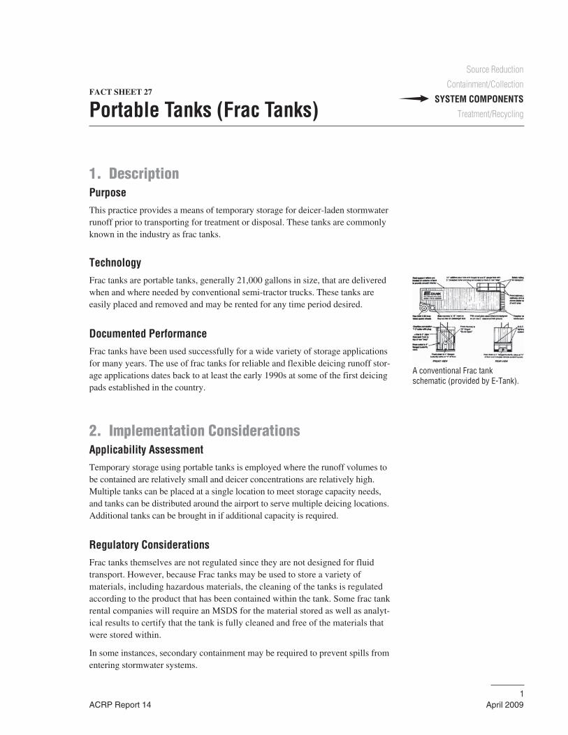
FACT SHEET 27
Portable Tanks (Frac Tanks)
1. DescriptionPurposeThis practice provides a means of temporary storage for deicer-laden stormwaterrunoff prior to transporting for treatment or disposal. These tanks are commonlyknown in the industry as frac tanks.
TechnologyFrac tanks are portable tanks, generally 21,000 gallons in size, that are deliveredwhen and where needed by conventional semi-tractor trucks. These tanks areeasily placed and removed and may be rented for any time period desired.
Documented PerformanceFrac tanks have been used successfully for a wide variety of storage applicationsfor many years. The use of frac tanks for reliable and flexible deicing runoff stor-age applications dates back to at least the early 1990s at some of the first deicingpads established in the country.
2. Implementation ConsiderationsApplicability AssessmentTemporary storage using portable tanks is employed where the runoff volumes tobe contained are relatively small and deicer concentrations are relatively high.Multiple tanks can be placed at a single location to meet storage capacity needs,and tanks can be distributed around the airport to serve multiple deicing locations.Additional tanks can be brought in if additional capacity is required.
Regulatory ConsiderationsFrac tanks themselves are not regulated since they are not designed for fluidtransport. However, because Frac tanks may be used to store a variety of materials, including hazardous materials, the cleaning of the tanks is regulatedaccording to the product that has been contained within the tank. Some frac tankrental companies will require an MSDS for the material stored as well as analyt-ical results to certify that the tank is fully cleaned and free of the materials thatwere stored within.
In some instances, secondary containment may be required to prevent spills fromentering stormwater systems.
ACRP Report 14 April 2009
Source Reduction
Containment/Collection
SYSTEM COMPONENTS
Treatment/Recycling
1
A conventional Frac tankschematic (provided by E-Tank).

Placement of frac tanks on the airfield must be in compliance with all applicableFAA regulations.
Planning and Design ConsiderationsThe following factors should be considered when planning for the use of fractanks for storage of deicer-laden stormwater runoff:
• Location of the tanks near the deicing area to simplify transfer into the tanksand minimize transport costs.
• Ease of transfer from the tanks to tankers for treatment or disposal.
• Assurance that the location of the frac tanks does not violate FAR Part 77 imag-inary surfaces (A landside location may be preferable to an airside location foreasier tank delivery/removal and tanker transfer.).
• Close coordination with the airport operations department to ensure that thelocation of the tanks does not affect other airfield operations.
• Provision of a level surface to take advantage of the full 21,000-gallonstorage capacity (Gravel or other material may be required to stabilize thesurface.).
• Advance coordination with the frac tank company well before the tanks areneeded onsite to ensure availability. (Better rates are often available for long-term rentals, i.e., those longer than 4 months.)
Integration with Other PracticesPortable frac tanks offer great flexibility in placement, being small enough tolocate around apron areas for short-term storage of runoff collected by glycolcollection vehicles or block-and-pump systems. Frac tanks may also be used asa temporary storage option while permanent tanks are being constructed orundergoing maintenance activities or until the runoff can be transported fordisposal.
Operation and Maintenance ConsiderationsMaintenance requirements are primarily associated with tank cleanout prior tomovement at the end of a lease term. Some manufacturers or providers offercleaning as a service included with the rental agreement. In this case, maintenanceon a rented frac tank is negligible.
Frac tanks are not meant for transporting liquids and should be moved onlywhen empty.
3. CostsAlthough they can be purchased, frac tanks are generally procured as rentedfacilities.
2 FACT SHEET 27
April 2009 ACRP Report 14

Capital CostsFrac tanks are not typically purchased, and therefore are not normally classified asa capital cost. Permanent, aboveground storage tanks (not frac tanks) are recom-mended for long-term storage, so frac tank purchase costs are not provided here.
Frac tanks are typically rented because they are used for temporary storage. Assuch, they can be leased for whatever time period they’re needed. However, thebest rates are obtained when tanks are rented for at least 4 months. Typical rentalfees are provided in Table 1.
Operations and Maintenance CostsFrac tanks require little in terms of operations and maintenance. However, onepotential cost is cleaning the tanks upon completion of their use. Frac tank manu-facturers require that the tanks be returned clean, and will charge a nominal feefor cleaning the tanks themselves or will require analytical results indicating thatthe tanks have been cleaned of the materials that were stored within them. Typicalfrac tank rental and cleaning fees are shown in Table 1.
FACT SHEET 27 3
ACRP Report 14 April 2009
Table 1. Typical Frac Tank Rental Fees
Fee Typical Range
Daily
Monthly
Long-term
Cleaning
$45/day
$1,350/mo
Up to 20% discount
$200/hr includingpressure washer,confined spaceentry, etc.
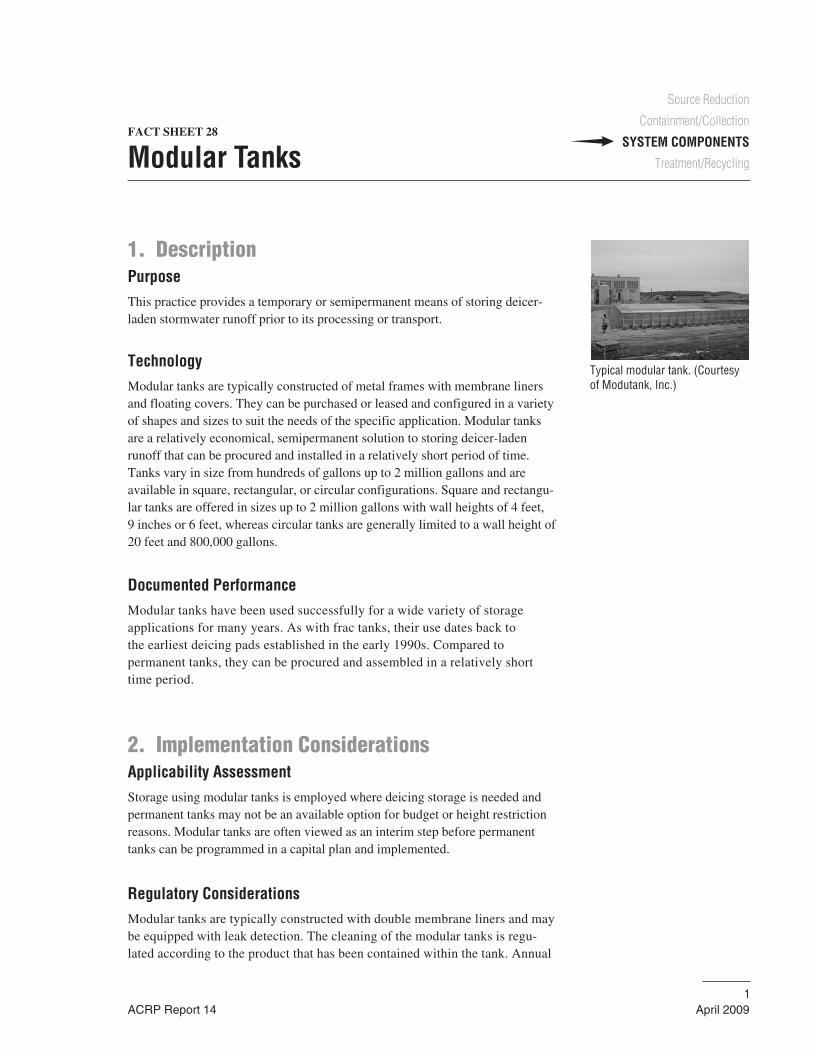
FACT SHEET 28
Modular Tanks
1. DescriptionPurposeThis practice provides a temporary or semipermanent means of storing deicer-laden stormwater runoff prior to its processing or transport.
TechnologyModular tanks are typically constructed of metal frames with membrane linersand floating covers. They can be purchased or leased and configured in a varietyof shapes and sizes to suit the needs of the specific application. Modular tanksare a relatively economical, semipermanent solution to storing deicer-ladenrunoff that can be procured and installed in a relatively short period of time.Tanks vary in size from hundreds of gallons up to 2 million gallons and areavailable in square, rectangular, or circular configurations. Square and rectangu-lar tanks are offered in sizes up to 2 million gallons with wall heights of 4 feet, 9 inches or 6 feet, whereas circular tanks are generally limited to a wall height of20 feet and 800,000 gallons.
Documented PerformanceModular tanks have been used successfully for a wide variety of storageapplications for many years. As with frac tanks, their use dates back to the earliest deicing pads established in the early 1990s. Compared to permanent tanks, they can be procured and assembled in a relatively shorttime period.
2. Implementation ConsiderationsApplicability AssessmentStorage using modular tanks is employed where deicing storage is needed andpermanent tanks may not be an available option for budget or height restrictionreasons. Modular tanks are often viewed as an interim step before permanenttanks can be programmed in a capital plan and implemented.
Regulatory ConsiderationsModular tanks are typically constructed with double membrane liners and maybe equipped with leak detection. The cleaning of the modular tanks is regu-lated according to the product that has been contained within the tank. Annual
ACRP Report 14 April 2009
Source Reduction
Containment/Collection
SYSTEM COMPONENTS
Treatment/Recycling
1
Typical modular tank. (Courtesyof Modutank, Inc.)

cleaning may be required, based on the disposition of the deicer-laden runoff,and may require a material safety data sheet (MSDS) for the material that wasstored as well as analytical results to certify that the tank is fully cleaned and freeof the materials that were stored within.
In lieu of double liners in a single modular tank, two single-liner tanks may benested one within the other and still comply with primary and secondary contain-ment requirements.
Placement of modular tanks on the airfield must be in compliance with all appli-cable FAA regulations.
Planning and Design ConsiderationsThe following factors should be examined when considering the use of modulartanks to store deicer-laden runoff:
• Need for the modular tanks to be located near the deicing area(s) to minimizetransport costs.
• Ease of transfer from the tanks to the onsite processing facility or tankers foroffsite treatment or disposal.
• Assurance that the location for the modular tank(s) does not violate FAR Part 77 imaginary surfaces (A landside location may be preferable to an airside location for easier tank delivery/removal and tanker transfer.).
• Need for a level surface to place the modular tank on so that full storagecapacity can be taken advantage of.
• Need for a sand or felt layer under the secondary liner to protect the linersfrom puncture.
• Fact that water may accumulate on the floating covers of these tanks, thuspossibility attracting waterfowl.
• Prevailing wind direction and proximity to occupied buildings because odorsfrom stored deicer-laden runoff may be an issue.
• Stainless steel bolts, nuts, and washers should be specified to aid in annualmaintenance and inspection.
• Weight adequate to hold down the liners prior to the tank being filled withfluid (Strong winds may float the liners out of place and potentially damagethem.).
Integration with Other PracticesModular tanks offer great flexibility in placement, being flexible enough to con-figure around apron areas for short-term storage of runoff collected by glycolcollection vehicles (see Fact Sheet 23) or block-and-pump systems (Fact Sheet 24).Modular tanks may also be used as storage while other, permanent tanks arebeing constructed or undergoing maintenance.
2 FACT SHEET 28
April 2009 ACRP Report 14
Typical modular tank construction.

Operation and Maintenance ConsiderationsMaintenance should be performed at least annually for the modular tank compo-nents and more frequently for the floating cover and liners. The steel componentsshould be inspected annually for corrosion or sharp edges that may abrade orpuncture the liner. The liners and floating cover should be inspected annually forleaks, punctures, or tears. Water accumulating on the surface of the tanks may be pumped off and disposed of as stormwater assuming an analytical test is conducted that confirms that the water is free of deicer-laden runoff.
3. CostsModular tanks may be purchased for long-term use or leased for shorter-termuse. The costs vary with the size of the tank, and also with the options chosen forthe tank.
Capital CostsModular tanks are available with different liner materials and different hardwaretypes (galvanized vs. stainless steel), etc. Typical purchase prices, excludingassembly and site preparation, are shown in Table 1.
Operations and Maintenance CostsModular tank components should be inspected annually for repair or replace-ment. The liners are the most important component of the modular tanks, andthey may need to be replaced every 3 to 5 years on average, possibly more fre-quently. There are costs associated with the annual inspection and cleaning;however, these would vary greatly with tank size. Once these tanks are erected,the operational costs are relatively low, primarily involving monitoring of anytank valves and fluid levels during periods of active filling or discharge.
FACT SHEET 28 3
ACRP Report 14 April 2009
Table 1. Typical ModularTank PurchaseFees
Typical Size (gal.) Cost* ($)
50,000 40,000
100,000 50,000
245,000 80,000
500,000 130,000
1,000,000 225,000
2,000,000 375,000
*Excluding shipping, site preparation,and installation which could be signifi-cant (more than 10% of tank cost)depending on the facility location andsite conditions.

FACT SHEET 29
Ponds
1. DescriptionPurposePonds provides for the onsite storage of collected deicing stormwater in openponds for subsequent release to onsite treatment, sanitary sewer, or surface waterin accordance with permit limitations.
TechnologyPonds (alternatively called basins or lagoons) provide a method for storing deicingrunoff prior to treatment or surface water discharge. In some cases, these facilitiesalso serve as nondeicing stormwater quantity and quality controls.
Although the primary function of ponds in deicer management systems is tem-porary detention of deicing runoff, ponds can also provide the benefits of solidssettling and some degree of equalization. Ponds may provide a treatment benefitrelative to deicing materials if detention time exceeds several weeks and theponds are aerated.
Aerated ponds may be used for pretreating deicing stormwater prior to its dis-charge to treatment, or treatment to achieve concentrations that can be dis-charged to surface waters in accordance with applicable permits. Removalefficiency is primarily a function of detention time, temperature, nutrient load,dissolved oxygen concentration, and the concentration of deicers in thestormwater.
Documented PerformanceThere is no performance metric to reflect storage. Treatment efficiency data arenot readily available.
2. Implementation ConsiderationsApplicability AssessmentPonds are often considered by airports because they generally represent the mostcost-effective means of storage available. There are, however, potential con-straints to be evaluated.
Ponds offer the following advantages:
• Generally represent the least costly alternative for storage of large volumes ofstormwater.
ACRP Report 14 April 2009
Source Reduction
Containment/Collection
SYSTEM COMPONENTS
Treatment/Recycling
1
• Generally do not pose the height restriction concerns that may be encounteredwith aboveground tanks, although this will depend on berm height and pondlocation relative to the aircraft operating area.
• The storage capacity of a pond can often be increased much less expensivelythan can other types of storage.
Potential constraints related to ponds include the following:
• Degradation of deicers is more likely to occur in an open basin than in a closedtank because of wind mixing and the increased availability of oxygen. For facil-ities that recycle glycol, this degradation could reduce yields of recoverableproduct. Unaerated and poorly mixed ponds may experience significant odorproblems from the anaerobic degradation of deicing compounds.
• Uncovered ponds may expose collected deicing stormwater to local surfacerunoff, sediment, and debris, which could interfere with treatment operations.
• Ponds used for storing deicing stormwater will typically require a liner to pre-vent impacts to groundwater. Drainage layers (e.g., geocomposites) below theliner may also be required to capture any leakage from the pond and, in somecases, to ensure that the pond liner will not “float” during periods of highgroundwater.
• Uncovered ponds may present a wildlife attraction hazard, especially whenconstructed close to the airfield. Floating covers or other mitigation measuresmay be required to satisfy FAA requirements. Covers that have the appear-ance of open water, such as black floating covers, may still attract wildlifeand may require camouflaging.
Other issues with ponds that should be considered:
• Ponds typically require a significantly larger footprint than other storageoptions, which may restrict potential locations.
• It is often more difficult to efficiently mix the contents of a pond than thecontents of a storage tank.
• Synthetic liners can be subject to damage from equipment and animals,necessitating repairs.
• Locating a pond in an area with a high groundwater table or numeroushigh-yield sand seams can make construction difficult due to dewateringrequirements.
Regulatory ConsiderationsFAA Advisory Circular 150/5200-33 (“Hazardous Wildlife Attractants on or NearAirports”) provides guidance on placement and design of stormwater detentionponds near airfields. Ponds may require a permit to install or a construction permitin some states. In many states, a dam permit is required if the pond berms are cer-tain heights above the lowest local discharge route. Compliance with groundwaterregulations (including separation distance from groundwater) should be carefullyevaluated before design and construction activities occur.
2 FACT SHEET 29
April 2009 ACRP Report 14
Planning and Design ConsiderationsPond design needs to be site-specific, with special consideration given to theproximity to aircraft operating areas, wildlife deterrence, odor generation andcontrol, solids removal, lining, and groundwater dewatering.
The following factors should be considered in pond design:
• In systems with onsite treatment, cost savings may be achieved by finding abalance between storage volume and treatment capacity. One aspect of deter-mining the storage volume is the volume required for the “design” stormevent, as well as the volume required for unforeseen circumstances whendischarge rates may be restricted. Other considerations for pond design arediscussed in Section 2.4.3 of the guidance document.
• Specialized outfall structures may be required to control the rate of dischargemore precisely and consistently than would be required for an ordinarystormwater pond.
Integration with Other PracticesStorage is often a central component in an airport’s overall deicing runoff manage-ment strategy, bridging the gap between collection and disposal by detaining col-lected deicing stormwater until it can be discharged to a glycol recovery system,onsite or offsite treatment, or surface water. Ponds can also play a role in an air-port’s overall stormwater management system, providing flow attenuation andwater quality benefits to stormwater during nondeicing periods.
Operation and Maintenance ConsiderationsOperational and maintenance requirements will vary from minimal to signifi-cant, depending on the site, pond design, and integration with treatment opera-tions. Requirements may include the operation of gates, pumps, mixers, valves,aerators, and monitoring equipment, depending on the specifics of the facility.
Most basins will require periodic sediment and debris removal and maintenanceof basin vegetation. Basins with a geosynthetic liner may require occasionalrepairs. Associated mechanical equipment will also require routine and preven-tative maintenance.
3. CostsOverall costs associated with ponds will vary by individual airport site, depend-ing on the design features selected. In general, ponds have low capital andannual costs relative to other storage options (e.g., underground detention andaboveground storage tanks).
Capital CostsCapital costs for constructing ponds consist of excavation of the basin itself, outletstructures, and associated pump stations and piping. Pond costs may significantly
FACT SHEET 29 3
ACRP Report 14 April 2009
Ponds have low capital andannual costs relative to otherstorage options
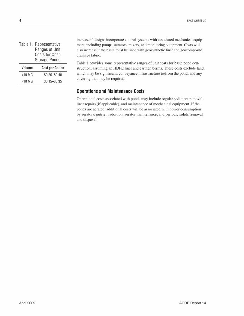
4 FACT SHEET 29
April 2009 ACRP Report 14
increase if designs incorporate control systems with associated mechanical equip-ment, including pumps, aerators, mixers, and monitoring equipment. Costs willalso increase if the basin must be lined with geosynthetic liner and geocompositedrainage fabric.
Table 1 provides some representative ranges of unit costs for basic pond con-struction, assuming an HDPE liner and earthen berms. These costs exclude land,which may be significant, conveyance infrastructure to/from the pond, and anycovering that may be required.
Operations and Maintenance CostsOperational costs associated with ponds may include regular sediment removal,liner repairs (if applicable), and maintenance of mechanical equipment. If theponds are aerated, additional costs will be associated with power consumptionby aerators, nutrient addition, aerator maintenance, and periodic solids removaland disposal.
Table 1. RepresentativeRanges of UnitCosts for OpenStorage Ponds
Volume Cost per Gallon
<10 MG $0.20–$0.40
>10 MG $0.15–$0.35
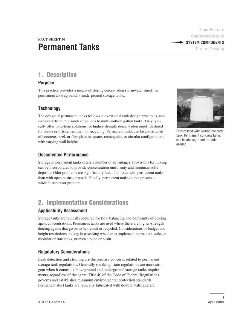
FACT SHEET 30
Permanent Tanks
1. DescriptionPurposeThis practice provides a means of storing deicer-laden stormwater runoff inpermanent aboveground or underground storage tanks.
TechnologyThe design of permanent tanks follows conventional tank design principles, andsizes vary from thousands of gallons to multi-million gallon tanks. They typi-cally offer long-term solutions for higher-strength deicer-laden runoff destinedfor onsite or offsite treatment or recycling. Permanent tanks can be constructedof concrete, steel, or fiberglass in square, rectangular, or circular configurationswith varying wall heights.
Documented PerformanceStorage in permanent tanks offers a number of advantages. Provisions for mixingcan be incorporated to provide concentration uniformity and minimize soliddeposits. Odor problems are significantly less of an issue with permanent tanksthan with open basins or ponds. Finally, permanent tanks do not present awildlife attractant problem.
2. Implementation ConsiderationsApplicability AssessmentStorage tanks are typically required for flow balancing and uniformity of deicingagent concentrations. Permanent tanks are used where there are higher-strengthdeicing agents that go on to be treated or recycled. Considerations of budget andheight restrictions are key in assessing whether to implement permanent tanks ormodular or frac tanks, or even a pond or basin.
Regulatory ConsiderationsLeak detection and cleaning are the primary concerns related to permanentstorage tank regulations. Generally speaking, state regulations are more strin-gent when it comes to aboveground and underground storage tanks require-ments, regardless of the agent. Title 40 of the Code of Federal Regulationsgoverns and establishes minimum environmental protection standards.Permanent steel tanks are typically fabricated with double walls and are
ACRP Report 14 April 2009
Source Reduction
Containment/Collection
SYSTEM COMPONENTS
Treatment/Recycling
1
Prestressed wire-wound concretetank. Permanent concrete tankscan be aboveground or under-ground.

equipped with leak detection systems. The cleaning of the tanks is regulatedaccording to the product that has been stored within the tank. Annual cleaningmay be required, based on the disposition of the deicer-laden runoff, and mayrequire a material safety data sheet for the material that was stored as well asanalytical results to certify that the tank is fully cleaned and free of the materi-als that had been stored.
Planning and Design ConsiderationsThe following issues should be examined when considering the use of permanenttanks to store deicer-laden runoff:
• Land availability and suitability.
• Site’s not violating FAR Part 77 imaginary surfaces (aboveground tanks).
• Geotechnical suitability, especially for larger tanks.
• Accurate sizing.
• Accessibility for future cleaning and removal of solids.
• Costs.
Integration with Other PracticesPermanent tanks are implemented as part of a glycol collection system, whichtypically incorporates a number of other practices from source reduction tocontainment and collection and to treatment and disposal.
Operation and Maintenance ConsiderationsPermanent storage tanks generally have lower maintenance requirements thanponds or basins. Maintenance should be performed at least annually for the tankand its components. Steel components as well as leak detection system compo-nents should be inspected annually.
3. CostsPermanent tanks are the most costly form of nonportable storage. The costs varywith the size of the tank, and also with the materials (concrete, steel, or fiberglass)and options chosen for the tank.
Capital CostsPermanent tank prices vary widely based on the size and materials. Steel tanksgenerally have a lower construction cost compared to tanks constructed of othermaterials. Tables 1 and 2 provide some basic guidance on unit costs for differentpermanent tank configurations.
2 FACT SHEET 30
April 2009 ACRP Report 14

Operations and Maintenance CostsOperations and maintenance costs associated with permanent tanks includeannual inspection, cleaning, and solids removal. These costs vary greatly basedon the size of the tank. Although steel tanks typically have a lower constructioncost, they have higher operating costs associated with inspection and mainte-nance of the coating system (paint).
FACT SHEET 30 3
ACRP Report 14 April 2009
Table 1. Aboveground StorageTank Capital Costs
Size (gal.) Typical Cost ($/gal.)
250,000 1.50–2.00
500,000 1.25–1.75
1,000,000 1.00–1.50
2,000,000 0.80–1.00
4,000,000 0.60–0.80
Note: Costs are for the tank and a shallow founda-tion; exclude pumps, piping, design costs, etc.
Table 2. Underground StorageTank Capital Costs
Size (gal.) Typical Cost ($/gal.)
3,000–6,000 2.50–4.00
10,000–20,000 2.00–2.50
FACT SHEET 31
Manual and Automated Diversion Valves
1. DescriptionPurposeThis practice provides controlled routing of deicing stormwater flows for thepurpose of collection, storage, treatment, and discharges. Diversion valves maybe automatic or manual.
TechnologyDiversion valves provide flexibility in managing stormwater with varying deicerconcentrations. Diversion valves may be used to direct stormwater to one of sev-eral destinations, including treatment, storage, or discharge. Installations vary incomplexity from manually operated valves to automated diversion systems thatoperate based on real-time monitoring.
Manual diversion valves are typically operated based on deicing conditions orweather observations (e.g., diversion to storage during deicing events and to sur-face water between events). Automated valves may allow flows to be managedmore precisely during deicing events. These valves may be actuated by a super-visory control and data acquisition (SCADA) system, which may make diversiondecisions based on online monitoring or management system information.
Several valve types are suitable for use in deicing runoff containment systems. Ingeneral, resilient gate valves or plug valves are preferred. Ultimately, any valveused for deicing runoff must have zero leakage and be chemically compatible.
Documented PerformanceAlthough data on the performance of diversion valves alone have not beencollected, a number of airports have implemented successful apron collectionsystems with manual and automated diversion valves. These airports include,but are not limited to, Portland International Airport, Detroit MetropolitanWayne County Airport, Baltimore Washington International ThurgoodMarshall Airport, Ted Stevens Anchorage International Airport, SeattleTacoma International Airport, and Dallas–Ft. Worth International Airport.
2. Implementation ConsiderationsApplicability AssessmentAlthough most airports will have some form of diversion valve for deicingstormwater management purposes, the appropriate type of valve may vary
ACRP Report 14 April 2009
Source Reduction
Containment/Collection
SYSTEM COMPONENTS
Treatment/Recycling
1
depending on the application. The variability of concentrations in the flows, aswell as storage, treatment, and operational requirements, are major considera-tions in deciding upon the level of complexity for diversion systems.
Advantages of automated valves include the following:
• Reduced manpower requirements for valve operation;
• Ability to be integrated into a SCADA system in conjunction with onlinemonitoring for automatic, real-time diversion decisions and centralized oper-ation of diversions throughout the system; and
• Improved National Pollutant Discharge Elimination System (NPDES) permitcompliance by reducing the chance for human error and improving the preci-sion of diversion decisions.
Advantages of manual valves include the following:
• Lower costs for valves and overall diversion systems;
• Retrofitting into existing storm sewer systems may be easier; and
• Simpler operation and maintenance.
Simple, manual diversion systems are appropriate for airports with relativelysimple deicer management systems that are operated infrequently or do notrequire changes often, and airports that collect and discharge all deicing runoff toa single destination.
More sophisticated and costly automated approaches may be justified at airports with management systems where operation can be optimized usingconcentration-based flow segregation. Automatic valves are often used inapplications requiring frequent diversion.
Regulatory ConsiderationsIf diversion valves are central to environmental compliance, operating conditionsfor collection or surface water discharge should be approved by regulators andincorporated into an airport’s NPDES (or equivalent) surface water dischargepermit. Permit conditions may stipulate valve locations, threshold concentrationsfor collection or discharge, operation schedule, valve operation protocols, andemergency upset conditions for valve operation.
Planning and Design ConsiderationsThe following factors should be considered in planning and implementation ofmanual or automated diversion valves:
• Diversion locations should be carefully selected with regard to collection effi-ciency, potential dilution, and integration with other system components suchas online monitoring.
• The selection of appropriate threshold concentrations for concentration-baseddiversion is essential to success.
2 FACT SHEET 31
April 2009 ACRP Report 14
• The complexity of the diversion valve system should be matched to theairport’s application, and the design of the diversion system should becoordinated with the overall deicing management system to optimizebenefits.
• When selecting a valve type, airports should consider operation and main-tenance, as well as cost. Key considerations for valve selection shouldinclude suitability for the application, reliability, and resistance to cloggingand corrosion.
• Vaults containing diversion valves should be protected from water intrusion,which may require sump pumps.
Integration with Other PracticesDiversion valve operation is typically integrated with a variety of practices.Valves can be used to divert flows to storage units, treatment systems, glycolrecovery systems, or discharges to surface water or a sanitary sewer. If auto-mated, valves may be tied into an overall deicer management control system.Control systems or airport personnel may use information from online monitor-ing or sampling, as well as storage and treatment system data, to make diversiondecisions that comply with effluent limits.
Operation and Maintenance ConsiderationsManual diversion valve systems are relatively straightforward to operate;however, they may require significant manpower, especially if the valves areoperated frequently. Manual valves should be installed such that they can beoperated easily by one person during the deicing season, without interferingwith airport operations. Manual valve operating procedures may require onlythat valves at deicing areas be diverted toward onsite storage or treatmentprior to the start of a deicing event. More complex manual systems may divert flows to different destinations, depending on deicing and monitoringobservations.
Automated diversion valve systems generally require less manpower to operatethan manual systems. Personnel are still required to occasionally remotely monitor and verify automated monitoring results and diversion decisions.Automated diversion systems can provide a factor of safety by ensuring theproper operation of the diversion system when it is not normally staffed by anoperator. Operating costs can be reduced if this automation enhances the abilityof personnel to multitask and attend to other components of the deicer manage-ment system.
Effective performance of this practice requires that the valves and valve struc-tures be maintained regularly. In general, regular inspections are required toverify functionality and to remove debris or address other potential hazards.Maintenance of automated systems may be more complex if it also involves themaintenance of integrated practices.
FACT SHEET 31 3
ACRP Report 14 April 2009
3. CostsOverall costs associated with manual diversion valve systems are low comparedto those of automated diversion valve systems. Diversion valve costs include thevalves themselves, additional practices and infrastructure, and costs to operatethe valves manually or automatically.
Capital CostsCapital costs include the valves themselves, in addition to associated equipmentand infrastructure, including diversion structures, piping, online monitoringequipment, and PLCs. Capital costs may vary significantly depending on thetype of valve, valve actuation, and valve size. Available data suggest that costmay fall within the range of $5,000–$100,000 per valve.
Operations and Maintenance CostsAnnual costs include wages for personnel to operate and inspect the diversionvalves, as well as maintenance costs for cleaning and repairing the valves anddiversion structures.
4 FACT SHEET 31
April 2009 ACRP Report 14

FACT SHEET 32
Real-Time Monitoring Technology
1. DescriptionPurposeThis practice provides the opportunity to more precisely manage aircraft andairfield deicers in runoff through real-time monitoring of key water quality con-stituents that reflect deicer content. This capability may be employed to selectivelyroute flows to different destinations based on concentration ranges, and track loadsin flows and to manage publicly owned treatment works (POTWs) and surfacewater discharges to meet concentration or load limits.
TechnologySensor technology has advanced to the point where real-time monitoring of bio-chemical oxygen demand (BOD), total organic carbon (TOC), or other surrogateparameters in stormwater flows is both feasible and practical. The use of an onlinemonitor provides near instantaneous measurement of water quality, reduces theerror associated with characterizing and managing continuous discharges based on aseries of discrete measurements, and reduces the risk of missing high-concentration,low-duration spikes of deicer concentrations that may occur in the runoff. It isthese capabilities that make concentration-based diversions possible by linkingreal-time monitoring to automated valves.
Different types of sensors can be used for this purpose. Several manufacturers sellinstrumentation that measure biological, physical, or chemical oxidation parame-ters, providing output that is analogous to laboratory-measured BOD, TOC, orchemical oxygen demand (COD). Each of these can be used as a surrogate for theorganic content of deicers. Online refractometers calibrated to glycols have beenused for this purpose as well, although their detection limits are generally higherthan those of the other technologies.
Documented PerformanceThe most appropriate performance metrics for this technology are detection limitand range. Table 1 provides representative information on the most commonlyused real-time monitoring technologies.
2. Implementation ConsiderationsApplicability AssessmentSeveral aspects of the application should be evaluated and understood when real-time monitoring technologies are being considered. First is the actual requirement
ACRP Report 14 April 2009
Source Reduction
Containment/Collection
SYSTEM COMPONENTS
Treatment/Recycling
1
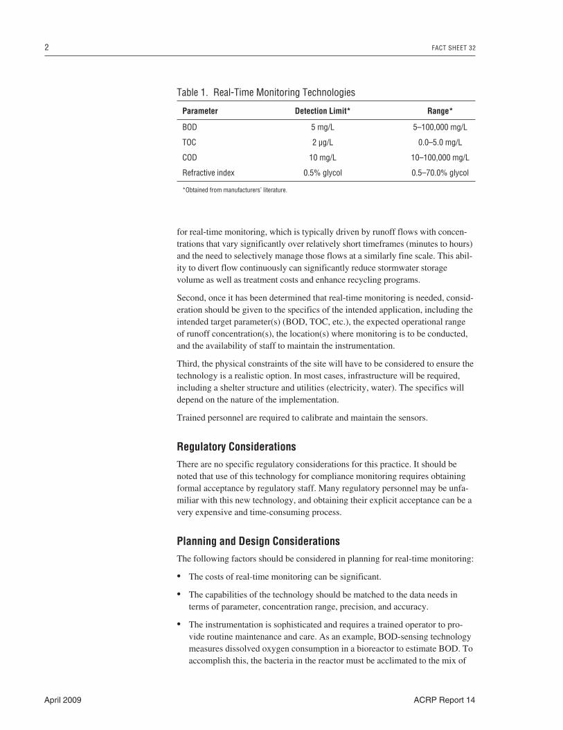
for real-time monitoring, which is typically driven by runoff flows with concen-trations that vary significantly over relatively short timeframes (minutes to hours)and the need to selectively manage those flows at a similarly fine scale. This abil-ity to divert flow continuously can significantly reduce stormwater storagevolume as well as treatment costs and enhance recycling programs.
Second, once it has been determined that real-time monitoring is needed, consid-eration should be given to the specifics of the intended application, including theintended target parameter(s) (BOD, TOC, etc.), the expected operational rangeof runoff concentration(s), the location(s) where monitoring is to be conducted,and the availability of staff to maintain the instrumentation.
Third, the physical constraints of the site will have to be considered to ensure thetechnology is a realistic option. In most cases, infrastructure will be required,including a shelter structure and utilities (electricity, water). The specifics willdepend on the nature of the implementation.
Trained personnel are required to calibrate and maintain the sensors.
Regulatory ConsiderationsThere are no specific regulatory considerations for this practice. It should benoted that use of this technology for compliance monitoring requires obtainingformal acceptance by regulatory staff. Many regulatory personnel may be unfa-miliar with this new technology, and obtaining their explicit acceptance can be avery expensive and time-consuming process.
Planning and Design ConsiderationsThe following factors should be considered in planning for real-time monitoring:
• The costs of real-time monitoring can be significant.
• The capabilities of the technology should be matched to the data needs interms of parameter, concentration range, precision, and accuracy.
• The instrumentation is sophisticated and requires a trained operator to pro-vide routine maintenance and care. As an example, BOD-sensing technologymeasures dissolved oxygen consumption in a bioreactor to estimate BOD. Toaccomplish this, the bacteria in the reactor must be acclimated to the mix of
2 FACT SHEET 32
April 2009 ACRP Report 14
Table 1. Real-Time Monitoring Technologies
Parameter Detection Limit* Range*
BOD 5 mg/L 5–100,000 mg/L
TOC 2 µg/L 0.0–5.0 mg/L
COD 10 mg/L 10–100,000 mg/L
Refractive index 0.5% glycol 0.5–70.0% glycol
*Obtained from manufacturers’ literature.

deicers in the runoff and properly maintained during periods when runoffdoes not contain deicing materials.
• The airport or aircraft operator must be committed to maintenance of theequipment on a 24/7 basis during the deicing season to ensure consistent andaccurate readings.
• Installations require protective housing and utilities in a location that is read-ily accessible for routine maintenance.
• Use for compliance monitoring requires gaining regulators’ acceptance.
Integration with Other PracticesReal-time monitoring technology is always implemented as part of an integrateddeicing runoff practice system. Most commonly, it is used in combination withan automated control system and motorized diversion valves to allow continuousstormwater segregation by concentration in the absence of a full-time operator.
Operation and Maintenance ConsiderationsProper operation and maintenance is essential for this technology to be effectiveand reliable. Requirements include the following:
• An experienced or trainable operator with good troubleshooting skills.
• Operation of the equipment within clearly defined conditions and ranges.
• Regular maintenance and calibration of all installed sensors.
3. CostsCapital CostsAvailable BOD and TOC sensors can measure a wide range of concentrationsbut are relatively expensive, with installed costs ranging between $50,000 and$150,000 per unit, which includes enclosures, utilities, and other supportingequipment.
Operations and Maintenance CostsThese technologies are relatively sophisticated and require regular maintenance,calibration, and troubleshooting by operators to ensure accuracy and reliability.The costs for training and maintenance will depend on the type of sensor and thelevel of training required for the individual maintaining the system.
FACT SHEET 32 3
ACRP Report 14 April 2009

FACT SHEET 33
Catch Basin Inserts/Valves
1. DescriptionPurposeThis practice provides a means of intercepting deicing stormwater before it canenter the storm sewer system and facilitating collection by glycol collectionvehicles.
TechnologyCatch basin inserts provide a physical barrier for containing deicing stormwateron the surface of the apron to allow time for collection or for testing prior to itsrelease. Inserts are typically installed in catch basins that receive surfacedrainage from aircraft deicing areas and are capable of being readily closed priorto the start of the deicing event and opened subsequently to allow clean runoff toenter the storm sewer system.
Different types of physical barrier are available. The simplest method consists ofa molded plastic drop-in panel with a depression in the bottom that serves as asump. These have limited practicality because they require that the storm gratebe lifted to install or remove the barrier. A more sophisticated and practicalapproach employs a metal sump installed under a catch basin grate and fittedwith a butterfly valve that can be operated with a T-handle from the surface. (See Figure 1.)
Inserts typically remain closed during the deicing event, although many operators keep them closed longer to prevent dry weather discharges ofdeicer. Depending on test results, the stormwater may then be released to the storm sewer or collected by a glycol recovery vehicle or vacuum truck.
Documented PerformanceThe performance of catch basin inserts for preventing the discharge of deicingstormwater depends largely on the effective operation of the stoppers or valvesand the integrity of the water-tight seal. The integrity of the catch basin structurebeyond the insert needs to be assessed prior to implementation. Some airportshave reported that catch basins leak if not properly sealed or maintained, and thatmaintaining seals that are exposed to sand and other debris can be problematic.In addition, any system that promotes ponding on the apron surface requires that pavement joints be sealed to prevent infiltration under the increased head(Switzenbaum et al., 1999). Performance is also affected by how quickly fluidscan be collected from the surface.
ACRP Report 14 April 2009
Source Reduction
Containment/Collection
SYSTEM COMPONENTS
Treatment/Recycling
1
Figure 1

2. Implementation ConsiderationsApplicability AssessmentCatch basin inserts are beneficial for use with a glycol recovery programemploying mobile collection vehicles. They allow the collection of deicingstormwater near the source, before it enters the storm sewer. This approach hasthe potential to minimize the overall volume of deicing stormwater that must bemanaged. They are also effective in preventing the unauthorized discharge ofdeicers under dry weather conditions (frost, for example).
The following factors should be considered when deciding whether catch basininserts are appropriate and applicable for an airport deicing stormwater manage-ment system:
• Operation and inspection of catch basin inserts, as well as glycol recoveryactivities, may require dedicated operators.
• Catch basin inserts must be custom-fabricated for individual catch basins, andcost varies with catch basin size.
• Catch basins need to be accessible by collection vehicles without interferingwith airport operations.
• Catch basin inserts and glycol recovery activities may result in the followingsituations, which could significantly interfere with airport safety and/oroperations:
– Potentially dangerous ponding during heavy precipitation if catch basininsert drains or valves are left closed.
– Added vehicular traffic in congested gate areas.
• The effectiveness of catch basin inserts and glycol recovery activities may belimited by the following airport characteristics:
– Irregular ground surfaces, which may prevent effective collection.
– Cracks or joints in pavement and catch basins, which could allow leaks tothe stormwater drainage system.
– Aircraft deicing areas with drainage areas that are large or not well-defined.
– Exposure of catch basins to debris, including sand and gravel.
Regulatory ConsiderationsInstallation and operation of catch basin inserts must be performed in compliance with FAA regulations. Ponding has the potential to interfere withairport and aircraft operations, and FAA Advisory Circular 150/5320-5C(“Surface Drainage”) recommends that ponding above apron catch basininlets be limited to a depth of 4 inches. Standard operating procedures should include upset conditions for opening valves when hazardous flooding occurs.
2 FACT SHEET 33
April 2009 ACRP Report 14
!Note: It is important toperform regular inspectionsto verify that catch basininserts are operatingproperly.

Planning and Design ConsiderationsThe following factors should be considered by airports in planning the imple-mentation of catch basin inserts:
• Appropriate locations for inserts or valves, including the likelihood or impactof ponding at those locations;
• Appropriate level of complexity for catch basin inserts;
• Inserts or valves must be sized to allow peak flows to pass without unaccept-able flooding;
• Standard procedures and protocols for preparation, inspection/monitoring,operation, and maintenance of the catch basin inserts, including thresholdconcentrations and upset conditions associated with hazardous flooding;
• Time and staffing required to operate inserts/valves and to collect pondeddeicing stormwater at each installation;
• Accessibility of catch basin insert locations by glycol recovery vehicles orvacuum trucks; and
• Plan to address potential leak points, including cracks in pavement or withindrainage infrastructure;
Integration with Other PracticesMost commonly, catch basin inserts are installed in designated deicing areas and operated in conjunction with collection vehicles, which collect the deicingstormwater that ponds above the inserts during deicing events. Catch basininserts may also be used for controlling deicer-laden snowmelt runoff or forapplications where the management of runoff is facilitated by keeping it out ofthe storm sewer system.
Operation and Maintenance ConsiderationsOperational requirements associated with catch basin valve inserts includemanual operation of the valves, periodic testing of the ponded stormwater, andtracking of the status of inserts during the deicing season. Maintenance tasksassociated with catch basin inserts include regular inspections of the catch basinstructures and inserts or valves to ensure functionality, removal of debris, andrepairs to maintain watertight seals. In some applications, removal of inserts orvalves is required at the end of the deicing season if non-deicing runoff ratesexceed the flow capacity of the insert.
3. CostsOverall costs associated with catch basin valve insert systems depend upon thenumber and sizes of catch basins that will require inserts as well as the initialcondition of the catch basins.
FACT SHEET 33 3
ACRP Report 14 April 2009
Capital CostsCapital costs for catch basin valve inserts consist primarily of the insert itself,which must be custom fabricated to fit a catch basin. Vendors have indicated thatthe cost of a single catch basin insert will vary with the size of the catch basin.Rough unit costs are reflected in one vendor’s quoted costs that range from$3,500 for a smaller catch basin to $5,500 for a larger catch basin (2007 prices).Installation of the inserts is often provided by the vendors as a separate cost item.Other initial costs may include repairs to existing catch basins and surroundingpavement to ensure an adequate water-tight seal.
Operations and Maintenance CostsOperational costs for catch basin inserts are those associated with monitoringand manual operation. Maintenance costs may include the following:
• Regular inspection of catch basin structures and inserts;
• Repairs to maintain proper operation and integrity of seal within catch basin; and
• Repairs to pavement surrounding catch basins to prevent infiltration ofponded deicing stormwater.
ReferenceSwitzenbaum, M. S., Veltman, S., Schoenberg, T., Durand, C., Mericas, D.,
& Wagoner, B. 1999. Best Management Practices for Airport DeicingStormwater. USA: University of Massachusetts/Amherst Water ResourcesResearch Center.
4 FACT SHEET 33
April 2009 ACRP Report 14
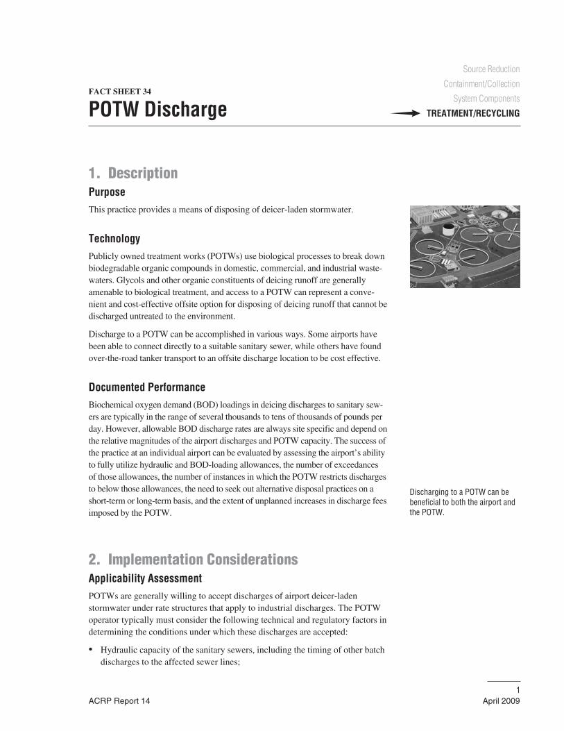
FACT SHEET 34
POTW Discharge
1. DescriptionPurposeThis practice provides a means of disposing of deicer-laden stormwater.
TechnologyPublicly owned treatment works (POTWs) use biological processes to break downbiodegradable organic compounds in domestic, commercial, and industrial waste-waters. Glycols and other organic constituents of deicing runoff are generallyamenable to biological treatment, and access to a POTW can represent a conve-nient and cost-effective offsite option for disposing of deicing runoff that cannot bedischarged untreated to the environment.
Discharge to a POTW can be accomplished in various ways. Some airports havebeen able to connect directly to a suitable sanitary sewer, while others have foundover-the-road tanker transport to an offsite discharge location to be cost effective.
Documented PerformanceBiochemical oxygen demand (BOD) loadings in deicing discharges to sanitary sew-ers are typically in the range of several thousands to tens of thousands of pounds perday. However, allowable BOD discharge rates are always site specific and depend onthe relative magnitudes of the airport discharges and POTW capacity. The success ofthe practice at an individual airport can be evaluated by assessing the airport’s abilityto fully utilize hydraulic and BOD-loading allowances, the number of exceedancesof those allowances, the number of instances in which the POTW restricts dischargesto below those allowances, the need to seek out alternative disposal practices on ashort-term or long-term basis, and the extent of unplanned increases in discharge feesimposed by the POTW.
2. Implementation ConsiderationsApplicability AssessmentPOTWs are generally willing to accept discharges of airport deicer-ladenstormwater under rate structures that apply to industrial discharges. The POTWoperator typically must consider the following technical and regulatory factors indetermining the conditions under which these discharges are accepted:
• Hydraulic capacity of the sanitary sewers, including the timing of other batchdischarges to the affected sewer lines;
ACRP Report 14 April 2009
Source Reduction
Containment/Collection
System Components
TREATMENT/RECYCLING
1
Discharging to a POTW can bebeneficial to both the airport andthe POTW.
• Hydraulic capacity of the treatment plant;
• BOD load capacity of the treatment plant;
• The variable and seasonal nature of the discharges as it affects plant perfor-mance and revenue streams;
• Limitations on POTW capacity during wet weather events;
• The potential effect of deicer additives on plant performance and the abilityof the plant to meet its own NPDES permit limitations; and
• Established policies, such as maximum fraction of POTW capacity that canbe allocated to a single discharger, and prohibition on stormwater dischargesto the plant.
Application for a POTW discharge permit will require characterization of the vol-umes and constituents in the proposed discharges, and may include requirementsfor bench-scale or pilot-scale treatability studies to demonstrate that the dischargewill not negatively impact the POTW’s operations or compliance with its ownNPDES permit.
POTWs have the ability to revoke discharge permits. This introduces a level of riskfor the airport if POTW discharge is the primary disposal practice. When planninga POTW discharge, it may be prudent to identify short- and long-term disposalcontingencies that can be implemented if access to the POTW is terminated orrestricted.
An airport’s decision to discharge to a POTW is typically based on the adequacyof treatment capacity offered by the POTW operator to meet the airport’s needs,capital costs for implementation, user fees, and reliability of service.
Regulatory ConsiderationsAn industrial discharge permit is typically required for discharging deicingstormwater to a sanitary sewer. These permits are issued by either the POTWoperator or a state agency that regulates POTWs. The permit will define theconditions and limits under which the wastewater will be accepted by thePOTW. Limits are typically based upon the treatment and hydraulic capacity ofthe POTW, the ability of the POTW to process the airport stormwater withoutcausing a plant upset, and possibly on the hydraulic capacity of the sanitarysewer being used. A construction or tap-in permit may also be required fromlocal or state regulators to access the existing sanitary sewer with a new sanitarysewer pipe.
Planning and Design ConsiderationsThe following factors should be considered in planning a successful POTWdischarge system:
• The airport’s flow rates and BOD loads requiring disposal under a variety ofweather conditions;
2 FACT SHEET 34
April 2009 ACRP Report 14
!It is important to identifyshort- and long-term contingencies in case thedischarge authorization isrevoked by the POTW.

• The available POTW hydraulic (flow) and BOD-loading capacity;
• Flow or loading restrictions that the POTW may consider during specialcircumstances (e.g., high flow conditions, plant upsets);
• User fee calculations for industrial discharges, including both volume and“high-strength” charges;
• Projections for changes in user fees in the next 10 years;
• Permit requirements;
• Potential sewer access points near the airport and the capacity of the sewers atthose locations;
• Storage requirements to contain large storm events under the constraints offlow and loading to the sanitary sewer;
• pH adjustment in collected deicing runoff discharges to the sanitary sewermay be required if the runoff is held for an extended period of time; and
• Alternative disposal options if the allowable discharges are decreased or theactual loadings are larger than expected.
Integration with Other PracticesHydraulic restrictions in the sanitary sewers or at the POTW, and the differencebetween airport discharge BOD concentrations (typically 500–50,000 mg/L)and POTW design influent concentrations (typically about 200 mg/L) almostalways require onsite storage and controlled release of deicing runoff dis-charges as part of an integrated system. These site-specific constraints andinterrelationships will define how POTW discharge is used to meet the airport’sprogram needs. The following practice system components are frequentlyrequired to implement the POTW discharge practice:
• Online monitoring/diversion systems to segregate low- and high-BOD con-centration stormwater;
• Onsite storage to equalize discharge flows and loads; and
• Monitoring and metering procedures to control the flow or BOD-loadingrates of discharges to the sanitary sewer.
Operation and Maintenance ConsiderationsOperational requirements associated with POTW discharges are associated prima-rily with monitoring (e.g., pollutant concentrations, flow rates, storage volumes) atkey locations in the system, and metering (flow rates and BOD loads discharged tothe sanitary sewer). Monitoring and metering can be achieved either manually orautomatically, depending on the system requirements and budget.
Adjusting pH may be required where deicing runoff is stored for extended peri-ods and anaerobic degradation lowers pH below that allowed in discharges to thePOTW.
FACT SHEET 34 3
ACRP Report 14 April 2009
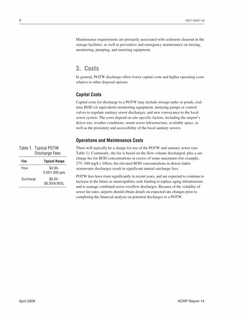
Maintenance requirements are primarily associated with sediment cleanout in thestorage facilities, as well as preventive and emergency maintenance on mixing,monitoring, pumping, and metering equipment.
3. CostsIn general, POTW discharge offers lower capital costs and higher operating costsrelative to other disposal options.
Capital CostsCapital costs for discharge to a POTW may include storage tanks or ponds, real-time BOD (or equivalent) monitoring equipment, metering pumps or controlvalves to regulate sanitary sewer discharges, and new conveyance to the localsewer system. The costs depend on site-specific factors, including the airport’sdeicer use, weather conditions, storm sewer infrastructure, available space, aswell as the proximity and accessibility of the local sanitary sewers.
Operations and Maintenance CostsThere will typically be a charge for use of the POTW and sanitary sewer (seeTable 1). Commonly, the fee is based on the flow volume discharged, plus a sur-charge fee for BOD concentrations in excess of some maximum (for example,275–300 mg/L). Often, the elevated BOD concentrations in deicer-ladenstormwater discharges result in significant annual surcharge fees.
POTW fees have risen significantly in recent years, and are expected to continue toincrease in the future as municipalities seek funding to replace aging infrastructureand to manage combined sewer overflow discharges. Because of the volatility ofsewer fee rates, airports should obtain details on expected rate changes prior tocompleting the financial analysis on potential discharges to a POTW.
4 FACT SHEET 34
April 2009 ACRP Report 14
Table 1. Typical POTW Discharge Fees
Fee Typical Range
Flow $4.00–5.50/1,000 gals
Surcharge $0.20–$0.30/lb BOD5
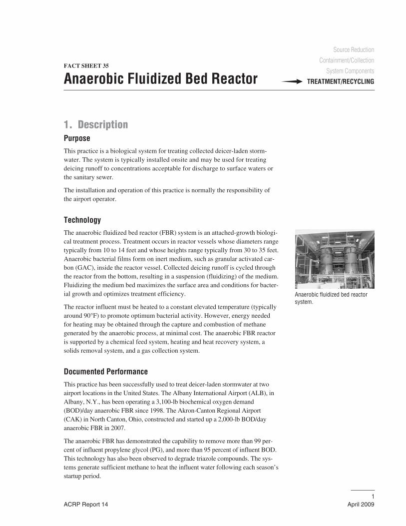
FACT SHEET 35
Anaerobic Fluidized Bed Reactor
1. DescriptionPurposeThis practice is a biological system for treating collected deicer-laden storm-water. The system is typically installed onsite and may be used for treatingdeicing runoff to concentrations acceptable for discharge to surface waters orthe sanitary sewer.
The installation and operation of this practice is normally the responsibility ofthe airport operator.
TechnologyThe anaerobic fluidized bed reactor (FBR) system is an attached-growth biologi-cal treatment process. Treatment occurs in reactor vessels whose diameters rangetypically from 10 to 14 feet and whose heights range typically from 30 to 35 feet.Anaerobic bacterial films form on inert medium, such as granular activated car-bon (GAC), inside the reactor vessel. Collected deicing runoff is cycled throughthe reactor from the bottom, resulting in a suspension (fluidizing) of the medium.Fluidizing the medium bed maximizes the surface area and conditions for bacter-ial growth and optimizes treatment efficiency.
The reactor influent must be heated to a constant elevated temperature (typicallyaround 90°F) to promote optimum bacterial activity. However, energy neededfor heating may be obtained through the capture and combustion of methanegenerated by the anaerobic process, at minimal cost. The anaerobic FBR reactoris supported by a chemical feed system, heating and heat recovery system, asolids removal system, and a gas collection system.
Documented PerformanceThis practice has been successfully used to treat deicer-laden stormwater at twoairport locations in the United States. The Albany International Airport (ALB), inAlbany, N.Y., has been operating a 3,100-lb biochemical oxygen demand(BOD)/day anaerobic FBR since 1998. The Akron-Canton Regional Airport(CAK) in North Canton, Ohio, constructed and started up a 2,000-lb BOD/dayanaerobic FBR in 2007.
The anaerobic FBR has demonstrated the capability to remove more than 99 per-cent of influent propylene glycol (PG), and more than 95 percent of influent BOD.This technology has also been observed to degrade triazole compounds. The sys-tems generate sufficient methane to heat the influent water following each season’sstartup period.
ACRP Report 14 April 2009
Source Reduction
Containment/Collection
System Components
TREATMENT/RECYCLING
1
Anaerobic fluidized bed reactorsystem.
2. Implementation ConsiderationsApplicability AssessmentThe following characteristics of anaerobic FBR systems should be consideredwhen evaluating the potential applicability of the practice to a particular airport:
• The system is well suited to treating high-concentration stormwater (the exist-ing systems have been designed to treat concentrations as high as 50,000 mg/Lof BOD).
• The system is highly applicable to airports where effluent limits are in termsof PG or ethylene glycol (EG), because the glycols are almost completelydestroyed in the treatment process.
• The anaerobic FBR can produce effluent with BOD concentrations as low as200 mg/L under typical design conditions.
• The system has a relatively small footprint, typically less than 0.1 acres, mak-ing it potentially appealing to airports with significant space constraints. Heightrestrictions may apply, depending on the system’s proximity to the airfield.
• The self-generation of methane to heat the water makes this practice a moreattractive option in climates where low temperatures may affect the efficiencyof open-air biological treatment systems.
• The system has shown the ability to degrade tolyltriazoles as well as petro-leum products. The ability to remove other aircraft-deicing fluid additives hasnot been studied.
Regulatory ConsiderationsConstruction of an anaerobic FBR system may require a permit-to-install or con-struction permit in some states. Approvals from the local fire marshal may alsobe required because of the methane handling system. Air permits for excessmethane emissions are not required.
Modifications to the facility’s National Pollutant Discharge Elimination System(NPDES) permit may be required to reflect appropriate monitoring requirementsfor treatment system effluent, as well as new outfall locations if applicable.
Planning and Design ConsiderationsThe following factors should be considered in the planning and implementationof an anaerobic FBR system:
• Performance data from existing systems can be used for a design basis, ifexpected influent loads are well-characterized. An onsite pilot-scale systemmay be used to optimize system performance and minimize cost.
• The system requires a continuous supply of an alkaline chemical to maintainneutral pH, as well as nutrient addition to maintain a healthy bacterial com-munity (as with other biological systems).
2 FACT SHEET 35
April 2009 ACRP Report 14
• Although sludge generation is low compared to aerobic systems, the meansfor sludge dewatering and offsite disposal (e.g., landfill disposal) should beconsidered.
• The system requires multiple utility connections, including potable water,electricity, and natural gas. Thus, the system may not be suitable for ruralsites with limited utilities.
• A minimum 2-year window should be allocated for design, bidding, construc-tion, and startup of an FBR system. Additional time may be necessary for othersystem components.
Integration with Other PracticesThe concentration and flow ranges suitable for the anaerobic FBR are compatiblewith the ranges of runoff concentrations associated with apron collection systems(see Fact Sheet 22), centralized deicing facilities (Fact Sheet 21), glycol collectionvehicles (Fact Sheet 23), block-and-pump systems (Fact Sheet 24), and snow meltsystems (Fact Sheet 26). Diversion valves can be used with real-time concentrationmonitoring to optimize the influent loading to the system, which can enhance sys-tem performance and reduce costs.
Storage capacity upstream of the system is essential for effective system operation.Designers can consider different combinations of storage and treatment capacitiesto achieve the most cost effective balance.
Operation and Maintenance ConsiderationsAirports with anaerobic FBR systems typically have utilized existing staff withmaintenance backgrounds as system operators. Staff should be trained by opera-tors experienced with an FBR system.
Adequate flow management controls built into the supervisory control and dataacquisition (SCADA) system reduce the likelihood of system upsets resultingfrom spike loadings. Because of the methane generation, it is recommended thatthe facility be staffed on all shifts or have an alarm callout and a SCADA systemcapable of remote monitoring and control.
Initial startup of the system can take 2 to 3 months, while the startup time forsubsequent seasons is typically 2 to 3 weeks. The anaerobic FBR is a low-maintenance system. Following the annual system shutdown at the end of thedeicing season, operators perform preventative maintenance on pumps andother system components. A 2,000-lb BOD/day system can be expected togenerate approximately 10 cubic yards of solids per year of dry solids thatwill require offsite disposal.
3. CostsCapital and operating costs for the anaerobic FBR treatment system are sitespecific, depending upon the deicer load to be treated, stormwater flow rates,
FACT SHEET 35 3
ACRP Report 14 April 2009

upstream storage capacity, and the effluent limit required in the discharge permit.
Capital CostsSignificant capital cost items for this practice include a building to house the treat-ment system, the reactors and media separation units, pumps, piping, online andoffline monitoring equipment, and SCADA system components. Capital costs perpound of BOD treated decrease as the required treatment capacity increases, mak-ing the systems more cost effective at higher loadings. Data from the two existingsystems suggest that capital costs may be in the range of $2.5–$10 million.
Operations and Maintenance CostsOperational cost items for this practice include power consumption, monitoringand analysis, solids disposal, and routine maintenance and repairs, with chemicaladdition (caustic, nutrients) as the largest cost item. Energy costs can be reducedthrough the use of methane generated by the system to heat the influent storm-water, as well as for heating the treatment building and other uses if excessmethane is available. There may be minimal costs associated with occasionalGAC replacement over time, however GAC regeneration is not required.
4 FACT SHEET 35
April 2009 ACRP Report 14
As an example, the estimatedO&M cost of the AFBR system atAkron is $95,000, not includingoperators’ wages.

FACT SHEET 36
Reciprocating SubsurfaceTreatment
1. DescriptionPurposeThis practice provides for the onsite biological treatment of collected deicer-ladenstormwater. The system may be used to treat the stormwater to concentrationsacceptable for discharge to surface waters or sanitary sewer.
TechnologyThe reciprocating subsurface treatment system is an attached-growth aerobicbiological treatment process. “Subsurface” refers to the fact that the storm-water remains below the surface of the gravel-filled treatment cells, avoidingopen water exposure. “Reciprocating” refers to the cyclical process by whichwater is pumped back and forth between gravel-filled basins. Bacteria areexposed to atmospheric oxygen in the first phase of the cycle and are exposedto deicing stormwater in the second phase of the cycle, eliminating the need tosupply supplemental oxygen.
Documented PerformanceThis practice has been successfully implemented to treat deicer-laden storm-water at one U.S. airport. Two separate systems were constructed in 2000 atDHL’s Wilmington Air Park (ILN) in Wilmington, Ohio. Each of the 5 acretreatment systems was designed to treat 50 to 300 gpm of flow at influent biochemical oxygen demand (BOD) concentrations ranging from 300 to 5,000 mg/L. The systems are designed to produce effluent with propylene gly-col (PG) and BOD concentrations of 10 mg/L to 200 mg/L. The actual effluentconcentrations depend upon the influent BOD loading. Seasonal removal rateshave averaged 93 percent. The ability to remove deicer additives has not beenevaluated.
As with any biological treatment system, removal efficiencies are a function oftemperature, with efficiencies improving as water temperatures increase. BODremoval efficiency at any particular point in time is dependent upon the designcapacity of the treatment system, influent BOD loadings, water temperature, andair temperature.
ACRP Report 14 April 2009
Source Reduction
Containment/Collection
System Components
TREATMENT/RECYCLING
1
Schematic cross-section of areciprocating subsurface system.

2. Implementation ConsiderationsApplicability AssessmentThe following factors should be considered when evaluating the applicability ofa reciprocating subsurface treatment system to a particular airport:
• The system is best suited for applications with high flows of low-concentration(<5,000 mg/L BOD) stormwater (e.g., widespread deicing collection areas),rather than low-flow, high-concentration applications (e.g., deicing pads). Itcan accommodate higher flow rates per pound of BOD or PG removed thanmany other treatment systems.
• The system is best suited for winter climates where water temperatures typi-cally vary between 36°F and 60°F, to avoid needing to heat the influent. Atcolder temperatures, treatment efficiency is reduced. At warmer tempera-tures, solids generation becomes excessive.
• If the influent loading to the system is optimized, effluent BOD, PG, and eth-ylene glycol (EG) concentrations less than 10 mg/L can be achieved at watertemperatures above 40°F. Low effluent concentrations become difficult toachieve at lower temperatures as treatment efficiency decreases.
• The system requires a larger footprint than other deicer treatment systems(typically several acres).
• Bird attraction is minimized if the system is designed to have the water levelremain below the gravel surface.
• Odors are minimal during winter months, but may become problematic withincreasing temperatures.
Regulatory ConsiderationsConstruction of a reciprocating subsurface treatment system may require a permit-to-install or construction permit in some states. Modifications to the facility’sNPDES permit may be required to reflect appropriate monitoring requirementsfor treatment system effluent, as well as new outfall locations if applicable.
Planning and Design ConsiderationsThe following factors should be considered in the planning and implementationof a reciprocating subsurface treatment system:
• A system’s footprint can be reduced by increasing the depth of the treat-ment basins, as long as the functionality and effectiveness of the system ismaintained.
• The size and cost of a system can be minimized by using storage and a SCADAsystem to optimize influent loadings to the system based on water temperature.
• Storage capacity upstream of the system is essential for effective system opera-tion. Designers can consider different combinations of storage and treatmentcapacities to achieve the most cost effective balance.
2 FACT SHEET 36
April 2009 ACRP Report 14

• As is the case with other biological treatment systems, nutrients must beadded to the treatment system to maintain a healthy bacterial community.
• The treatment system bacterial population can develop from bacteria presentin stormwater, so there is no need for purchased bacterial seed. Design perfor-mance levels can be reached in two to four weeks, depending on water temper-atures and loading rates.
• A minimum 2-year window should be allocated for schematic design andpilot testing of the system. An additional 2-year period should be allocatedfor design, bidding, construction, and startup.
Integration with Other PracticesA reciprocating subsurface system is compatible with the range of deicing runoffconcentrations associated with apron collection systems (Fact Sheet 22) and air-field drainage systems (Fact Sheet 25). The technology is also compatible withsystems where diversions separate low- and high-concentration streams, allowingload to be optimized by blending these streams.
Operation and Maintenance ConsiderationsOne to three full-time operators are required to run and maintain a reciprocatingsubsurface treatment system, depending upon the size and complexity of the sys-tem. As with other systems, management of flow rates in and out of the systemare critical and can be complex at times. The required degree of active operatorinvolvement is dependent upon the degree of automatic controls integrated intothe system design.
Maintenance tasks typically include annual preventative maintenance on pumpsand weed control. Solids buildup can be managed if operational ranges are met, orelse significant effort may be needed to clean or replace the media.
3. CostsCapital and operating costs for the subsurface reciprocating treatment system aresite specific, depending upon design load and flow rates, upstream storage capac-ity, degree of SCADA control, climate, and effluent limits.
Capital CostsSignificant capital cost items for this practice include treatment cell construc-tion, gravel media, pump stations, monitoring equipment, and SCADA systemcomponents. For lower concentration, higher flow rate stormwater streams,the reciprocating subsurface treatment system can have a significant costadvantage over other treatment technologies. Available data from the existingsystem at ILN suggests a potential capital cost range of $2 million to $8 million.
FACT SHEET 36 3
ACRP Report 14 April 2009
Reciprocating subsurface treatment system.

Operations and Maintenance CostsOperational cost items for this practice include nutrient addition, power con-sumption, monitoring and analysis, and routine maintenance and repairs. Powercosts are relatively low because pumps typically run 15–25 percent of the time inwinter and are off in the summer. Major maintenance cost items include yearlypump preventative maintenance. Available data from existing systems suggestsan annual cost range of $20,000–$50,000, not including labor.
4 FACT SHEET 36
April 2009 ACRP Report 14

FACT SHEET 37
Moving Bed Bioreactor Treatment System
1. DescriptionPurposeThis practice is a biological treatment system for treating collected deicer-ladenstormwater. The system is typically installed onsite and may be used for pretreat-ing stormwater prior to discharging it to a sanitary sewer, or to treat the stormwaterto concentrations acceptable for discharging it to surface water.
The installation and operation of this fact sheet is normally the responsibility ofthe airport operator.
TechnologyThe moving bed biofilm reactor (MBBR) is an aerobic attached-growth biologi-cal treatment process. In the MBBR system, biomass grows on a polyethylenecarrier (media element) that is shaped to maximize biofilm growth and reducethe reactor size needed for a given level of treatment.
The carriers are suspended in the reactor tank liquid through the buoyant actionof air pumped through a network of diffuser manifolds in the bottom of the reac-tor. The air provides the aerobic conditions necessary for the bacteria to grow.The system will not function under anaerobic conditions.
Biosolids are formed in the MBBR system when the biofilm thickness increasesto the point that the bacteria closest to the media can no longer get oxygen and thefilm sloughs off the media. The solids are carried out of the reactor with thetreated wastewater and must be removed, which typically is accomplishedthrough a dissolved air flotation system.
Documented PerformanceThe MBBR process has been implemented at one European airport and bench-scale tested at one U.S. airport.
The Oslo Airport uses an MBBR plant to treat stormwater with influent concentra-tions of up to 2,000 mg/L of glycol. The system was constructed in the spring of2004. Geothermal energy is used to heat the influent stormwater stream by routingit through underground caverns prior to treatment. The system removes about90 percent of the glycol in the influent stream and is reported to remove oxylatesassociated with surfactant additives. The Pittsburgh International Airport hasbench-scale tested a three-stage MBBR system for treatment of dilute airfieldrunoff. In general, bench-scale tests using stormwater from the airport spiked with
ACRP Report 14 April 2009
Source Reduction
Containment/Collection
System Components
TREATMENT/RECYCLING
1
Plastic media.
aircraft and pavement deicer have demonstrated the potential to achieve an effluentBOD concentration as low as 10 mg/L. However, achievement of this concentra-tion was observed to be highly temperature-dependent. Effluent concentrations of10 mg/L BOD at temperatures typical of winter stormwater were inconsistent.
2. Implementation ConsiderationsApplicability AssessmentThe following characteristics of an MBBR should be considered when evaluat-ing the potential applicability of this treatment fact sheet at a particular airport:
• The system is best suited to treatment of lower biochemical oxygen demand(BOD) concentration stormwater (less than 1,000 mg/L).
• The MBBR process is capable of achieving low effluent concentrations (as lowas 10 mg/L) in bench-scale testing.
• Heating influent stormwater will improve performance, but it is not necessaryto achieve treatment, if the relationship between temperature and removal effi-ciency is understood and accounted for in the system design. The cost associ-ated with system size requirements to achieve 10 mg/L BOD versus the cost ofheating the influent should be evaluated. Further, the ability of the system toconsistently achieve 10 mg/L BOD effluent limits at very low temperaturesshould be considered with respect to associated permit limits in which exceedence of 10 mg/L may be considered a permit violation.
• The system has a relatively small footprint, typically less than 0.1 acre.
Regulatory ConsiderationsConstruction of a MBBR system may require a permit-to-install or constructionpermit in some states.
In some instances, system effluent may discharge to the receiving waters throughnew outfalls, necessitating modification to the facility’s National PollutantDischarge Elimination System (NPDES) permit.
The monitoring requirements, including frequency and types of samples, that areincluded in the NPDES permit for a treatment system discharge should be consid-ered carefully, as they may vary from the monitoring requirements associated withan untreated stormwater discharge.
Planning and Design ConsiderationsThe following factors should be considered in the planning and implementationof an MBBR system:
• Pilot testing is recommended to establish treatment rates, achievable efflu-ent concentrations, and temperature effects on deicer-laden stormwaterfrom the site.
2 FACT SHEET 37
April 2009 ACRP Report 14
• The treatment process will produce sludge that requires dewatering and disposal. The expected quantity of sludge produced and its moisture con-tent, density, and settling characteristics should be determined in the pilot-testing stage.
• Two operators are typically recommended, with the operators trained byexperienced operators of existing MBBR systems.
Integration with Other PracticesThe MBBR system is effective at treating lower concentration influent, making itcompatible with apron collection systems (see Fact Sheet 22) and airfield drainagesystems. The technology is also compatible with systems where diversion valvesseparate high- and low-concentration streams, and performance can be optimizedby blending these streams to maintain a constant load to treatment. Storage capac-ity upstream of the treatment system in the form of ponds (Fact Sheet 29) or per-manent tanks (Fact Sheet 30) is essential for effective and efficient operation. Therequired storage capacity can be accurately determined if the temperature-loadingrate relationship is integrated into the system operation and the variation in storm-water flow rates and BOD-glycol concentrations in the collected stormwater areunderstood.
Operation and Maintenance ConsiderationsAs is the case with other biological systems used to treat deicer-laden stormwater,nutrients must be added to the treatment system to maintain healthy bacterialcommunities. Oxygen must also be provided to the reactor to maintain aerobicconditions. The operators are responsible for maintaining the correct nutrientbalance and oxygen supply.
The MBBR system will produce biosolids that require dewatering and disposal.Dewatering system requirements will vary depending on the characteristics of thesludge produced by the system.
A wastewater treatment background is not necessary for a treatment system oper-ator as long as training can be provided by operators experienced in operating anMBBR system.
Adequate flow management controls built into the supervisory control and dataacquisition system (SCADA) reduce the likelihood of system upsets resultingfrom spike loadings.
Initial startup of the system can take several months, depending upon the degreeto which the reactor is seeded with bacteria.
3. CostsCapital and operating costs for the MBBR treatment system are site specific,depending upon the deicer load to be treated, stormwater flow rates, upstreamstorage capacity, the effluent limit parameters, and the numeric effluent limits.
FACT SHEET 37 3
ACRP Report 14 April 2009

Capital CostsSignificant capital costs for this fact sheet include a building to house the treatmentsystem, reactors, blowers or oxygen generation equipment, sludge-dewateringequipment, sludge storage, pumps, piping, online and offline monitoring equipment, and SCADA system components.
Operations and Maintenance CostsOperational costs for this fact sheet include chemical addition, power consumption,monitoring and analysis, and routine maintenance and repairs.
Maintenance cost items include yearly preventative maintenance and transport/disposal of dry sludge to a landfill.
4 FACT SHEET 37
April 2009 ACRP Report 14

FACT SHEET 38
Sequencing Batch Reactor
1. DescriptionPurposeThis practice is a biological treatment system for treating collected deicer-ladenstormwater onsite. The system may be used for pretreating stormwater prior toits being discharged to a sanitary sewer, or it may be used to treat the stormwaterto concentrations acceptable for discharging it to surface water.
The implementation and operation of this practice would typically be the respon-sibility of an airport authority.
Although this treatment technology is proven, its application to winter stormwateris a recent development. As a result, this practice should be considered an emerg-ing technology.
TechnologyA sequencing batch reactor (SBR) is an aerobic biological treatment system thatrepresents a variation of the activated sludge process typically used at municipalpublicly owned treatment works (POTWs). As other activated sludge processes do,the SBR works by developing a mixed culture of bacteria suspended in the waste-water. However, where the typical activated sludge system is a continuous flow-through process, the wastewater in an SBR is treated in batches that undergo asequence of steps of filling, holding, settling, and decanting. The advantage ofSBR is that at lower flow rates, it is typically more cost effective than conventionalactivated sludge because the equalization, aeration, treatment, and sludge-settlingsteps are all carried out in a single reactor. An SBR can be sized to process flowsup to several hundred gallons per minute. SBR systems are often designed so thatthe concentration is stepped down in a series of reactors, rather than having alltreatment performed within a single, larger-scale reactor. Using a series of reactorsallows for smaller-scale, more-cost-effective system components. Having multipletreatment units also provides the operator with greater flexibility and control overthe treatment process, allowing the process to be adjusted for variations in influentflow rates and concentrations.
Documented PerformanceInitial studies evaluating the SBR for treatment of deicer-laden stormwater wereperformed in 1997 for Chicago’s O’Hare International Airport. The studies indi-cated that the SBR technology reduced influent biochemical oxygen demand(BOD) concentrations of 7,000 mg/L to less than 10 mg/L, making it a potentiallyviable technology for deicer treatment. The studies also identified problems withslime buildup and elevated suspended solids.
ACRP Report 14 April 2009
Source Reduction
Containment/Collection
System Components
TREATMENT/RECYCLING
1
A full-scale SBR was operated at the Cincinnati/Northern Kentucky Airport in2004 and 2005. This facility was designed to treat dilute stormwater flows at theheadwaters to one of the airport’s two receiving streams. The design flow rate was1,040 gpm, and the design influent and effluent BOD values were 1,200 mg/L and50 mg/L, respectively. Although the system performed well during moderate con-ditions, maintaining the bacterial population during periods of high-BOD andlow-BOD loading and low temperatures was difficult. Because the system did notperform well under variable load scenarios, it was abandoned and has been turnedinto sludge basins.
2. Implementation ConsiderationsApplicability AssessmentThe SBR process is potentially applicable to situations where low-effluent BODconcentrations are required; however, achievable effluent concentrations willdepend upon site-specific conditions and influent characteristics. Successful appli-cation requires that a relatively constant BOD load be maintained, along withwater temperatures greater than 41°F, in order to optimize the biological popula-tion. As with other biological treatment practices, frequent variations in the BODload may result in unreliable treatment efficiency if the biological population isunable to respond accordingly.
Regulatory ConsiderationsConstruction of an SBR system may require a permit-to-install or constructionpermit in some states.
SBR systems may need to comply with industrial discharge permit requirementsif they are used for pretreating stormwater that is being discharged to a POTW.Alternatively, if the system discharges to surface water, it would need to meet allNPDES permit (or equivalent) surface water discharge requirements, includingdischarge-monitoring requirements. The monitoring requirements, including fre-quency and types of samples, that are included in the NPDES permit for a treat-ment system discharge should be considered carefully, because they may varyfrom the monitoring requirements associated with untreated stormwater discharges.
In some instances, system effluent may discharge to the receiving watersthrough new outfalls, which would require modification to the facility’sNPDES permit.
Planning and Design ConsiderationsAirports interested in an SBR system as a practice should consider the followingin their planning and implementation:
• SBR systems require that the BOD load be maintained relatively constantthroughout the season to maintain the bacterial population. This require-ment may be met using a system that segregates stormwater by concentra-
2 FACT SHEET 38
April 2009 ACRP Report 14

tion and then blends the streams to maintain an optimal loading throughoutthe season.
• Because the system requires that temperature be maintained above 41°F, ameans of heating the influent stream should be considered.
• Typical operating conditions should be identified to support the design of thesystem, including influent loads, concentrations, and flows, as well as desiredeffluent concentration.
• Construction and operation of a pilot-scale system will allow examination ofthe applicability of this treatment system for a particular airport and stormwaterstream.
• Successful operation of the SBR system requires support equipment in the form of storage tanks, online monitoring, and potentially a blendingsystem.
• A means for disposing of sludge produced during treatment operations willbe required.
• Standard operating procedures for use of SBR should be developed in con-junction with an overall deicer management system.
• A training program for system operators will be required. It is recommendedthat operators be trained by experienced operators of SBR systems.
Integration with Other PracticesBecause an SBR is best suited to treating lower-concentration stormwater, it maybe used in conjunction with apron collection systems (Fact Sheet 22) or airfielddrainage systems (Fact Sheet 25). The technology is also compatible with systemswhere high- and low-concentration streams are separated.
An SBR may be used to pretreat stormwater prior to its discharge to a POTW. Italso may be paired with treatment or recycling technologies that are capable ofhandling higher-concentration influent streams.
Operation and Maintenance ConsiderationsThe SBR system may require one to two full-time operators. Licensed operatorsmay not be required, although requirements may vary from state to state.
Operational and maintenance issues to consider include sludge processing and dis-posal, and regulation of stormwater temperature and loading. Additional mainte-nance may be required to address any slime buildup that occurs within the reactor.
3. CostsCapital and operating costs for an SBR system will be site specific and dependupon the deicer load to be treated, stormwater flow rates, upstream storagecapacity, climate, and the effluent limits.
FACT SHEET 38 3
ACRP Report 14 April 2009
Capital CostsSignificant capital cost items for this practice include construction of the reactorstructures, blowers, and diffuser system; supervisory control and data acquisition(SCADA) system components; solids handling; and sludge dewatering.
Operations and Maintenance CostsOperational cost items for this practice include full-time operator(s), nutrientaddition, power consumption, monitoring and analysis, sludge disposal, androutine maintenance and repairs.
4 FACT SHEET 38
April 2009 ACRP Report 14
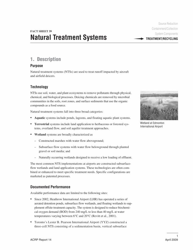
FACT SHEET 39
Natural Treatment Systems
1. DescriptionPurposeNatural treatment systems (NTSs) are used to treat runoff impacted by aircraftand airfield deicers.
TechnologyNTSs use soil, water, and plant ecosystems to remove pollutants through physical,chemical, and biological processes. Deicing chemicals are removed by microbialcommunities in the soils, root zones, and surface sediments that use the organiccompounds as a food source.
Natural treatment systems fall into three broad categories:
• Aquatic systems include ponds, lagoons, and floating aquatic plant systems.
• Terrestrial systems include land application to herbaceous or forested sys-tems, overland flow, and soil aquifer treatment approaches.
• Wetland systems are broadly characterized as
– Constructed marshes with water flow aboveground;
– Subsurface flow systems with water flow belowground through plantedgravel or soil media; and
– Naturally occurring wetlands designed to receive a low loading of effluent.
The most common NTS implementations at airports are constructed subsurface-flow wetlands and land application systems. These technologies are often com-bined or enhanced to meet specific treatment needs. Specific configurations aremarketed as patented processes.
Documented PerformanceAvailable performance data are limited to the following sites:
• Since 2002, Heathrow International Airport (LHR) has operated a series ofaerated detention ponds, subsurface flow wetlands, and floating wetlands to sup-plement offsite treatment capacity. The system is designed to reduce biochemi-cal oxygen demand (BOD) from 240 mg/L to less than 40 mg/L at watertemperatures varying between 6°C and 20°C (Revitt et al., 2001).
• Toronto’s Lester B. Pearson International Airport (YYZ) constructed athree-cell NTS consisting of a sedimentation basin, vertical subsurface
ACRP Report 14 April 2009
Source Reduction
Containment/Collection
System Components
TREATMENT/RECYCLING
1
Wetland at EdmontonInternational Airport

flow system, and surface flow marsh for storing and treating runoffdesigned to achieve a 73 percent reduction in BOD (Flindall and Basran, 2001).
• A pilot-scale NTS was implemented at the Airborne Air Park in Wilmington,Ohio (ILN) with six gravel-bed cells totaling 0.12 acres. Results indicatedBOD removal rates of greater than 90 percent with reciprocation of the waterbetween cells to periodically expose the bacterial film to the atmosphere(USEPA, 2000). A 6-acre system designed for an average loading of 3,200 lbsCBOD/day was subsequently installed (USDOD, 2004).
• The Westover Air Reserve Base in Massachusetts has operated a demonstrationsubsurface flow wetland since 2002. During 10 monitored deicing events, thissystem reduced the BOD concentrations in runoff by 11–78 percent and toler-ated peak concentrations of 974–15,098 mg/L (USDOD, 2004).
• Edmonton International Airport (EIA) operates 6.7 acres of horizontal sub-surface flow wetlands from April to September to treat stored deicingrunoff. The system is designed to treat 0.34 mgd of 1,400-mg/L ethyleneglycol to 100 mg/L ethylene glycol and 25 mg/L BOD (Higgins andMacLean, 2002).
• Buffalo Niagara International Airport (BUF) is constructing a 13.6-acre systemof aerated horizontal subsurface flow wetlands. Pilot studies indicated greaterthan 95 percent BOD removal and a 10-fold improvement in removal rate con-stants (3.8 d−1 aerated vs. 0.4 d−1 unaerated) at 4°C using the proprietary design(Higgins et al., 2006).
2. Implementation ConsiderationsApplicability AssessmentLand requirements are the major consideration in assessing the potential appli-cability of natural treatment. Land requirements depend on the type of technol-ogy, influent runoff quality, required effluent quality, and drainage areatreated. Representative sizes and types of NTS implementations are providedin Table 1.
It is also important to consider the existing drainage infrastructure to determine ifan NTS will fit within the confines of the airport, and if the flow must be pumpedor conveyed by gravity.
Available information indicates that deicing treatment wetlands are designed forrunoff concentrations of up to 1,353 mg/L ethylene glycol (Edmonton) and up to5,000 mg/L BOD (Toronto). Measurements of inflow concentrations to theWestover ARB showed peak inflow concentrations during spring events of15,098 mg/L. Design concentrations are typically lower, ranging from 108 mg/LBOD (Heathrow) and 500 mg/L (Toronto). Design criteria are based upon pilotstudy results (e.g., Buffalo, Heathrow, Wilmington) or in the case of Toronto andWestover, from the general literature on treatment wetlands for wastewaters ofhigh organic strength (Kadlec and Knight, 1996).
2 FACT SHEET 39
April 2009 ACRP Report 14
Table 1. Examples of NTSSize and Type
Airport Construction
Edmonton CN
Toronto CN
Heathrow UK
Wilmington OH
Westover ARB MA
Buffalo NY
6.7 ac, horizontalsubsurface flow
1.0 ac, verticalsubsurface flow3.4 ac, surfaceflow
5.1 ac subsurfaceflow2.5 ac, floatingmat
6.0 ac, recipro-cating subsur-face flow
0.6 ac, horizon-tal subsurfaceflow
13.6 ac, aeratedsubsurface flow

Regulatory ConsiderationsBird airstrike hazards (BASHs) are a critical safety consideration at airports.Available data indicate that deicing treatment wetlands are not necessarily anattractive habitat, and that wildlife populations can be managed effectively.
Many local municipalities are beginning to require low-impact development (LID)stormwater management on development within their purview. Incorporating anNTS as a deicing and stormwater practice may be viewed as an LID-type practice.
Planning and Design ConsiderationsSizing and estimating performance for these systems are generally accomplishedusing accepted empirical first-order BOD removal sizing models (e.g., Kadlec andKnight, 1996). No standardized model exists for the design of treatment wetlandsfor aircraft and airfield deicer removal.
The need for reliable performance during cold weather and minimized wildlifehazards poses significant challenges to NTS applications at airports. However,methods are available to address these concerns. Vegetation species can bechosen that pose minimal or less desirable waterfowl food sources. Surfacewater drawdown durations within the treatment system can be reduced to mini-mize habitat value to water fowl. Finally, the vegetation in some NTS may bemowed regularly to avoid forming large stands that could represent attractivehabitat.
Hydraulic surface flow routing is a critical design factor in delivering runoff to theNTS. To avoid pumping, it is best to site the NTS downgradient of the sources ofrunoff to be treated. Existing drainage systems typically require modification toaccommodate this practice.
Pilot-scale testing is generally recommended to account for site-specific variationsin climate, site characteristics, storm water runoff characteristics, and the generallack of standard design guidelines for natural treatment systems.
Integration with Other PracticesNTSs can be combined with other practices as part of an integrated system.Frequently, the highest-strength runoff is isolated and collected for recycling or other suitable treatment, and lower strength runoff is routed to the NTS.Conveyance design may also provide opportunities to incorporate benefits suchas solids settling or actual BOD removal.
Operation and Maintenance ConsiderationsNTSs typically require much lower maintenance than other treatment practices.With favorable conditions and proper design, there are very few moving parts inthese systems.
A trained operator who understands the operating principles and conditions ofthe system will be required. Typically, water level adjustments will be required afew times a year based on seasonal changes in runoff.
FACT SHEET 39 3
ACRP Report 14 April 2009
Storage in winter and treatment in summer may be an option. The subsurface flowwetland at Edmonton only operates outside of frozen conditions and must impoundwater or collect contaminated snow in winter. During very cold weather, cold airdrawn into the beds of the wetland cells at Wilmington freezes the bacteria, andwater must be impounded during these periods of no biological activity.
Vegetation management may be required to minimize BASH, or to maintainappropriate hydraulic flow conditions. Mowing or hand cutting during thesummer may be required.
3. CostsConstruction costs of full-scale wetlands to treat de-icing fluids vary dependingupon size, flow, and operating season. Cost data presented here are for preliminaryguidance only.
Capital CostsTable 2 summarizes available capital cost data. Per-acre costs vary from $543,000to $2,000,000. Conveyance and pumping systems and site infrastructure installationtypically make engineered media systems more costly than wetland projects.
Operations and Maintenance CostsAverage annual reported operating costs for an NTS facility are about $3,000 peryear. General cost data from the treatment wetland literature indicate an averagerange of operation and maintenance costs of $1,000 to $2,000 per acre per year(Kadlec and Knight, 1996). Maintenance activities may be included with other siteoperation activities with negligible cost effect.
ReferencesRevitt, D. M., Worral, P., & Brewer, D. 2001. The integration of constructed
wetlands into a treatment system for airport runoff. Water Science andTechnology: A Journal of the International Association on Water PollutionResearch, 44(11–12), 469–476.
Flindall, R. and D. S. Basran. 2001. Design of a Constructed Wetland for theTreatment of Glycol Contaminated Stormwater. Chapter 14, pp. 201–211 in:W. James (ed). Models and Applications to Urban Water Systems. Vol. 9.
US EPA—Office of Water. 2000. Preliminary data summary: Airport deicingoperations (revised); Chapter 7 (wastewater containment and treatment) andChapter 8 (wastewater characterization) (EPA Preliminary Data SummaryNo. EPA-821-R-00-016).
U.S. Department of Defense. 2004. ESTCP cost and performance report:Enhanced biological attenuation of aircraft deicing fluid runoff using constructed wetlands (No. CP-0007).
4 FACT SHEET 39
April 2009 ACRP Report 14
Table 2. Examples of NTS Capital Costs
Airport Construction
Edmonton $1,800,000
Toronto $2,000,000
Heathrow $20,000,000
Westover $326,000
Higgins, J. W. and M. MacLean. 2002. The Use of a Very Large ConstructedSub-Surface Flow Wetland to Treat Glycol-Contaminated Stormwater fromAircraft De-Icing Operations. Res. J. Canada 37(4):785–792.
Higgins, J. W., L. Deschaines, K. Minkel, and M. Liner. 2006. The Use of LargeSubsurface Flow Wetlands to Treat Glycol-Contaminated Stormwaterfrom Airport De-Icing Operations. Poster presented at 10th InternationalConference on Wetland Systems for Water Pollution Control. LisbonPortugal.
Kadlec, R. H., and R. L. Knight. 1996. Treatment Wetlands. CRC Press/LewisPublishers. Boca Raton, FL.
FACT SHEET 39 5
ACRP Report 14 April 2009
FACT SHEET 40
Membrane Filtration
1. DescriptionPurposeMembrane filtration refers to a number of related physical treatment processesthat can be applied to segregate deicer-laden stormwater into dilute and con-centrated streams.
The implementation of this practice is typically by an airport or a glycol recoverycontractor.
TechnologyMembrane filtration physically separates dissolved substances on the basis ofmolecular size. The membranes have pores that allow water molecules to passthrough while blocking larger molecules, such as glycols and other deicer con-stituents. The result is increased concentrations of glycols and other deicers inthe “concentrate (reject)” stream and a “dilute (permeate)” stream.
Ultrafiltration (UF) and reverse osmosis (RO) are applications of the membrane fil-tration principle. In UF, relatively low hydrostatic pressures (less than 100 poundsper square inch, or psi) are employed to separate relatively large molecules. Incontrast, RO uses significantly higher pressures to remove relatively smallermolecules, such as metal ions, aqueous salts, and organic compounds.
Components of a membrane treatment system include pretreatment to removesuspended solids and hydrocarbons, chemical feed for pH adjustment and scalecontrol, the RO treatment train, and a system for membrane cleaning. Theinfluent may be heated to optimize the removal efficiency.
RO is usually operated as a staged system. The concentrate from the first stagefeeds the second stage, which further increases the concentration in the rejectstream and reduces the stream’s volume. The concentrate volume from a two-stage RO system is typically from 5 to 25 percent of the feed volume.
Membrane filtration systems at airports are used primarily to support glycolrecovery from runoff with deicer concentrations greater than 1%. In these appli-cations, the stream from a two-stage RO system is often further concentrated byadditional processing to obtain a saleable product.
Membrane filtration systems can also be used in nonrecycling applications toachieve a low concentration dilute stream potentially suitable for surface waterdischarge. In these applications, disposal of the concentrate stream via publicowned treatment works (POTW) discharge or other means is required. MunichInternational Airport has tested RO to reduce the volume of airfield runoffdischarged to the POTW.
ACRP Report 14 April 2009
Source Reduction
Containment/Collection
System Components
TREATMENT/RECYCLING
1
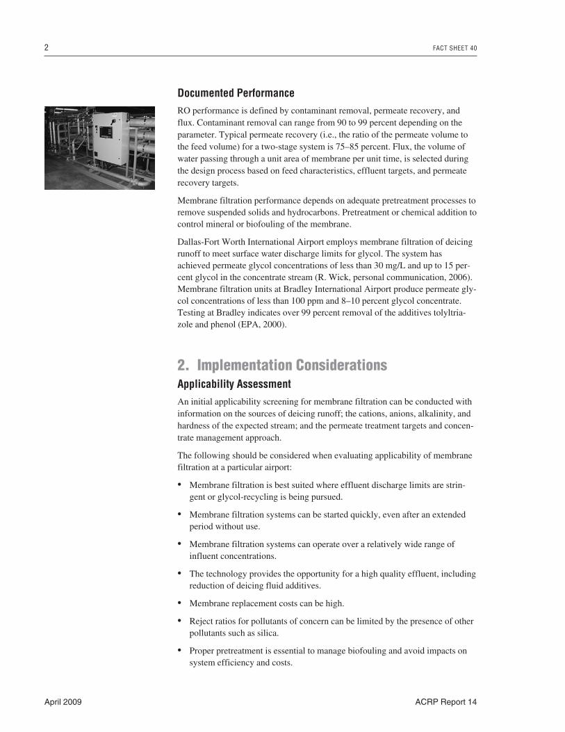
Documented PerformanceRO performance is defined by contaminant removal, permeate recovery, andflux. Contaminant removal can range from 90 to 99 percent depending on theparameter. Typical permeate recovery (i.e., the ratio of the permeate volume tothe feed volume) for a two-stage system is 75–85 percent. Flux, the volume ofwater passing through a unit area of membrane per unit time, is selected duringthe design process based on feed characteristics, effluent targets, and permeaterecovery targets.
Membrane filtration performance depends on adequate pretreatment processes toremove suspended solids and hydrocarbons. Pretreatment or chemical addition tocontrol mineral or biofouling of the membrane.
Dallas-Fort Worth International Airport employs membrane filtration of deicingrunoff to meet surface water discharge limits for glycol. The system hasachieved permeate glycol concentrations of less than 30 mg/L and up to 15 per-cent glycol in the concentrate stream (R. Wick, personal communication, 2006).Membrane filtration units at Bradley International Airport produce permeate gly-col concentrations of less than 100 ppm and 8–10 percent glycol concentrate.Testing at Bradley indicates over 99 percent removal of the additives tolyltria-zole and phenol (EPA, 2000).
2. Implementation ConsiderationsApplicability AssessmentAn initial applicability screening for membrane filtration can be conducted withinformation on the sources of deicing runoff; the cations, anions, alkalinity, andhardness of the expected stream; and the permeate treatment targets and concen-trate management approach.
The following should be considered when evaluating applicability of membranefiltration at a particular airport:
• Membrane filtration is best suited where effluent discharge limits are strin-gent or glycol-recycling is being pursued.
• Membrane filtration systems can be started quickly, even after an extendedperiod without use.
• Membrane filtration systems can operate over a relatively wide range ofinfluent concentrations.
• The technology provides the opportunity for a high quality effluent, includingreduction of deicing fluid additives.
• Membrane replacement costs can be high.
• Reject ratios for pollutants of concern can be limited by the presence of otherpollutants such as silica.
• Proper pretreatment is essential to manage biofouling and avoid impacts onsystem efficiency and costs.
2 FACT SHEET 40
April 2009 ACRP Report 14
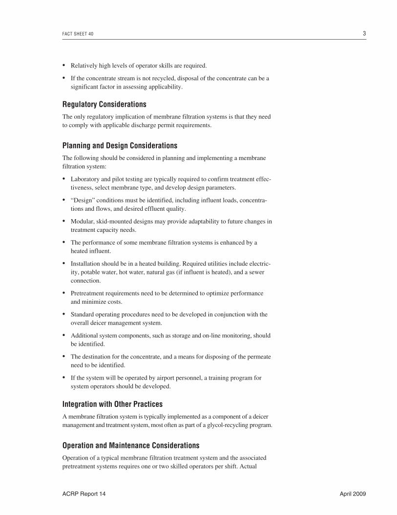
• Relatively high levels of operator skills are required.
• If the concentrate stream is not recycled, disposal of the concentrate can be asignificant factor in assessing applicability.
Regulatory ConsiderationsThe only regulatory implication of membrane filtration systems is that they needto comply with applicable discharge permit requirements.
Planning and Design ConsiderationsThe following should be considered in planning and implementing a membranefiltration system:
• Laboratory and pilot testing are typically required to confirm treatment effec-tiveness, select membrane type, and develop design parameters.
• “Design” conditions must be identified, including influent loads, concentra-tions and flows, and desired effluent quality.
• Modular, skid-mounted designs may provide adaptability to future changes intreatment capacity needs.
• The performance of some membrane filtration systems is enhanced by aheated influent.
• Installation should be in a heated building. Required utilities include electric-ity, potable water, hot water, natural gas (if influent is heated), and a sewerconnection.
• Pretreatment requirements need to be determined to optimize performanceand minimize costs.
• Standard operating procedures need to be developed in conjunction with theoverall deicer management system.
• Additional system components, such as storage and on-line monitoring, shouldbe identified.
• The destination for the concentrate, and a means for disposing of the permeateneed to be identified.
• If the system will be operated by airport personnel, a training program forsystem operators should be developed.
Integration with Other PracticesA membrane filtration system is typically implemented as a component of a deicermanagement and treatment system, most often as part of a glycol-recycling program.
Operation and Maintenance ConsiderationsOperation of a typical membrane filtration treatment system and the associatedpretreatment systems requires one or two skilled operators per shift. Actual
FACT SHEET 40 3
ACRP Report 14 April 2009
staffing requirements depend on the system size, number of unit processes, andnumber of treatment trains. System operation is often contracted out to a glycolrecovery company.
Maintenance requirements include routine backflushing of the pretreatmentprocesses. Media filters are typically backwashed daily with filtered effluent,and UF systems are cleaned weekly with caustic and detergent solutions.Membrane cleaning is based on the type of fouling experienced and can includeuse of acids, bases, detergents, or enzymes. Proper system cleaning and shut-down for the off-season is critical for prolonging membrane life (typically 3–5 years).
3. CostsCosts associated with this practice will depend on site-specific factors and con-straints including responsibility for equipment ownership, and system operationand maintenance.
Capital CostsCapital cost items could include the membrane filtration units, storage tanks,pump stations, pretreatment equipment, control systems, and a building. Capitalcosts increase with influent flow rate and decreasing effluent concentrations.Available capital cost data for existing membrane filtration systems ranges from$1 million to $8 million.
Operations and Maintenance CostsOperating and maintenance cost items may include chemicals, power, naturalgas, solids disposal, and membrane replacement. Costs for POTW discharge ortransport of the concentrate to an offsite treatment facility can be significant.Available data for existing membrane filtration systems suggest annual operatingcosts from $150,000 to $800,000.
ReferenceEPA. 2000. Preliminary Data Summary: Airport De-Icing Operations. EPA-821-
R-00-016. From http://www.epa.gov/waterscience/guide/airport/.
4 FACT SHEET 40
April 2009 ACRP Report 14
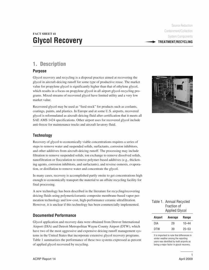
FACT SHEET 41
Glycol Recovery
1. DescriptionPurposeGlycol recovery and recycling is a disposal practice aimed at recovering theglycol in aircraft-deicing runoff for some type of productive reuse. The marketvalue for propylene glycol is significantly higher than that of ethylene glycol,which results in a focus on propylene glycol in all airport glycol-recycling pro-grams. Mixed streams of recovered glycol have limited utility and a very lowmarket value.
Recovered glycol may be used as “feed stock” for products such as coolants,coatings, paints, and plastics. In Europe and at some U.S. airports, recoveredglycol is reformulated as aircraft-deicing fluid after certification that it meets allSAE AMS 1424 specifications. Other airport uses for recovered glycol includeanti-freeze for maintenance trucks and aircraft lavatory fluid.
TechnologyRecovery of glycol to economically viable concentrations requires a series ofsteps to remove water and suspended solids, surfactants, corrosion inhibitors,and other additives from aircraft-deicing runoff. The processing may includefiltration to remove suspended solids, ion exchange to remove dissolved solids,nanofiltration or flocculation to remove polymer-based additives (e.g., thicken-ing agents, corrosion inhibitors, and surfactants), and reverse osmosis, evapora-tion, or distillation to remove water and concentrate the glycol.
In many cases, recovery is accomplished partly onsite to get concentrations highenough to economically transport the material to an offsite recycling facility forfinal processing.
A new technology has been described in the literature for recycling/recoveringdeicing fluids using polymeric/ceramic composite membrane-based vapor per-meation technology and low-cost, high-performance ceramic ultrafiltration.However, it is unclear if this technology has been commercially implemented.
Documented PerformanceGlycol application and recovery data were obtained from Denver InternationalAirport (DIA) and Detroit Metropolitan Wayne County Airport (DTW), whichhave two of the most aggressive and expensive deicing runoff management sys-tems in the United States that incorporate extensive glycol recovery programs.Table 1 summarizes the performance of these two systems expressed as percentof applied glycol recovered by recycling.
ACRP Report 14 April 2009
Source Reduction
Containment/Collection
System Components
TREATMENT/RECYCLING
1
Table 1. Annual RecycledFraction ofApplied Glycol
Airport Average Range
DIA 29 10–44
DTW 39 25–53
It is important to note that differences inwinter weather among the reportingyears was identified by both airports asbeing a major factor in glycol recovery.

2. Implementation ConsiderationsApplicability AssessmentThe feasibility of glycol recovery is dependent on collecting sufficient volumesof adequately high concentrations of glycol in runoff to reach an economicallysustainable scale.
• Mixed-glycol streams are generally impractical to recycle because the resultingproduct has a very low market value. This means that only propylene glycol–based aircraft deicing fluid (ADF) and aircraft anti-icing fluid (AAF) may beused in the areas where deicing runoff is to be recycled to ensure the highestvalue of the recovered material.
• A critical criterion for recycling is collection of runoff with glycol concentra-tions that are high enough to make recovery economical. Minimum concentra-tions should be in the range of 3 to 5 percent, whereas average concentrationsshould be significantly higher.
• The volume of high-concentration runoff that is collected will determine thefeasibility of onsite processing versus offsite transport for processing. Only thelargest airports are likely to generate the volume of concentrated runoff neces-sary to support onsite-processing facilities.
• Smaller airports may be able to implement recycling if they are able to trans-port collected runoff economically to a recycling facility that serves otherairports and/or industries. If the runoff volumes are large enough, limitedonsite processing to reduce water content may make transport more economically feasible.
• It is technically feasible to recover glycol to concentrations in excess of 98 per-cent, although energy requirements and cost increase significantly with concen-trations. Therefore, glycol is concentrated only as much as necessary to meetthe needs of the reuse application.
Regulatory ConsiderationsWaste streams from the recycling process, if performed on airport grounds, mustbe properly permitted and handled. This may require an industrial dischargepermit for sanitary sewer discharges, and/or pretreatment and solids disposal.
Air emissions from onsite processing and over-the-road transport may be ofregulatory concern, depending on location.
Planning and Design ConsiderationsSeveral airports in North America have active glycol-recycling programs. Thestrategies and scales of these recycling operations vary significantly, determinedby site-specific factors such as volume and reliability of ADF usage, glycolconcentrations in collected runoff, volume of high-concentration runoff, andproximity to processing facilities.
Practical onsite glycol recycling is generally restricted to the largest airports,where large volumes of glycol are used annually.
2 FACT SHEET 41
April 2009 ACRP Report 14
Five percent is a common lowerlimit for economically recoverableglycol, but at least one program(T. F. Green Airport) operateswith a threshold concentration of3 percent.
Airports with Active GlycolRecycling Programs
Detroit Metropolitan WayneCounty
Toronto’s Lester B. PearsonInternational
Denver International
Cincinnati/NorthernKentucky International
Pittsburgh International
Minneapolis–St. PaulInternational
Newark International
Salt Lake City International
Washington Dulles International
Bradley International
T. F. Green
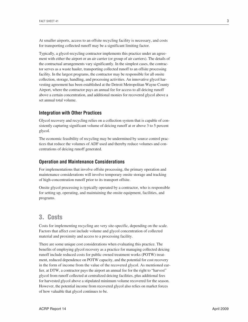
At smaller airports, access to an offsite recycling facility is necessary, and costsfor transporting collected runoff may be a significant limiting factor.
Typically, a glycol-recycling contractor implements this practice under an agree-ment with either the airport or an air carrier (or group of air carriers). The details ofthe contractual arrangements vary significantly. In the simplest cases, the contrac-tor serves as a waste hauler, transporting collected runoff to an offsite processingfacility. In the largest programs, the contractor may be responsible for all onsitecollection, storage, handling, and processing activities. An innovative glycol har-vesting agreement has been established at the Detroit Metropolitan Wayne CountyAirport, where the contractor pays an annual fee for access to all deicing runoffabove a certain concentration, and additional monies for recovered glycol above aset annual total volume.
Integration with Other PracticesGlycol recovery and recycling relies on a collection system that is capable of con-sistently capturing significant volume of deicing runoff at or above 3 to 5 percentglycol.
The economic feasibility of recycling may be undermined by source control prac-tices that reduce the volumes of ADF used and thereby reduce volumes and con-centrations of deicing runoff generated.
Operation and Maintenance ConsiderationsFor implementations that involve offsite processing, the primary operation andmaintenance considerations will involve temporary onsite storage and trackingof high-concentration runoff prior to its transport offsite.
Onsite glycol processing is typically operated by a contractor, who is responsiblefor setting up, operating, and maintaining the onsite equipment, facilities, andprograms.
3. CostsCosts for implementing recycling are very site-specific, depending on the scale.Factors that affect cost include volume and glycol concentration of collectedmaterial and proximity and access to a processing facility.
There are some unique cost considerations when evaluating this practice. Thebenefits of employing glycol recovery as a practice for managing collected deicingrunoff include reduced costs for public owned treatment works (POTW) treat-ment, reduced dependence on POTW capacity, and the potential for cost recoveryin the form of income from the value of the recovered glycol. As mentioned ear-lier, at DTW, a contractor pays the airport an annual fee for the right to “harvest”glycol from runoff collected at centralized deicing facilities, plus additional feesfor harvested glycol above a stipulated minimum volume recovered for the season.However, the potential income from recovered glycol also relies on market forcesof how valuable that glycol continues to be.
FACT SHEET 41 3
ACRP Report 14 April 2009