acr systems trh manual · with its programmed instructions. it is not warranted to be error-free....
TRANSCRIPT

Copyright © 2010 ACR Systems Inc. All Rights Reserved.
Reference Guide
IMPORTANT!
TRH Data Loggers
Test Equipment Depot - 800.517.8431 - 99 Washington Street Melrose, MA 02176 - TestEquipmentDepot.com

All rights reserved. No parts of this work may be reproduced in any form or by any means- graphic, electronic, or mechanical, including photocopying, recording, taping, orinformation storage and retrieval systems - without the written permission of ACRSystems Inc.
Products that are referred to in this document may be either trademarks and/or registeredtrademarks of the respective owners. The publisher and the author make no claim tothese trademarks. For more information regarding trademarks, see the "TrademarkNotices" section of this manual.
ACR Systems Inc. assumes no responsibility for errors or omissions, or for damagesresulting from the use of information contained in this document or from the use ofprograms and source code that may accompany it. In no event shall the publisher and theauthor be liable for any loss of profit or any other commercial damage caused or allegedto have been caused directly or indirectly by this document.
Copyright © 2010 ACR Systems Inc. All Rights Reserved.
TRH Data Loggers

TrendReader is a Registered Trademark of ACR Systems Inc.
TRADEMARK NOTICES

ACR Systems Inc. warrants the hardware to be free from defects in workmanship andcomponents provided they are not abused or subjected to detrimental conditions. Refer tothe warranty information included with your logger for details.
Software is warranted for one year from the date of purchase, to operate in accordancewith its programmed instructions. It is not warranted to be error-free. If the product doesnot perform in accordance with this Limited Warranty, ACR will at its discretion, eitherrepair or replace the product free of charge. There will, however, be a charge for freightand Canadian Customs clearance (if applicable). Any replacement hardware or softwarewill be warranted for the remainder of the original warranty period. To the maximumextent permitted by applicable laws, ACR Systems Inc. disclaims all other warranties,either expressed or implied, including but not limited to, implied warranties of fitness for aparticular application. In no event shall ACR Systems Inc. be liable for anyinconveniences, loss, damages, etc., whatsoever arising out of the use of this product.
ACR's policy is not to proceed with any repairs or replacement unless first discussed withACR's Technical Support Analysts and an RMA (Return Material Authorization) number isissued.
LIMITED WARRANTY

IContents
Copyright © 2010 ACR Systems Inc. All Rights Reserved.
Table of Contents
Section I TRH Data Loggers 1............................................................................................................................................ 11 Introduction to TRH
........................................................................................................................................................... 1Features
........................................................................................................................................................... 1Description
........................................................................................................................................................... 2Programmed Operation
........................................................................................................................................................... 2How TRH Loggers Take Readings
........................................................................................................................................................... 3How to Use TRH Loggers
........................................................................................................................................................... 5Specifications
........................................................................................................................................................... 6Product Approvals
............................................................................................................................................ 72 TRH Software Driver ........................................................................................................................................................... 7Logger Status
................................................................................................................................................. 7Logger Sampling
................................................................................................................................................. 8Logger Memory
........................................................................................................................................................... 10Logger Channels
................................................................................................................................................. 10Channel Information
................................................................................................................................................. 11Channel Calibration
............................................................................................................................................ 123 TRH-1000 Temperature & Relative Humidity Logger ........................................................................................................................................................... 12Description
........................................................................................................................................................... 12Setup
........................................................................................................................................................... 13Troubleshooting
........................................................................................................................................................... 13Relative Humidity Calibration
............................................................................................................................................ 144 APPENDIX A TRH-1000 Sample Rates ........................................................................................................................................................... 14How a Data Logger Stores Readings
........................................................................................................................................................... 14Sample Rate Table
Index 16

WELCOME
Congratulations on your purchase of a TRH-1000 data logger. We are confident that youwill find it to be a most valuable and useful tool for your data collection applications.
This Reference Guide is designed to be used hand-in-hand with TrendReader Standardsoftware and frequently refers to TrendReader Standard conventions and procedures. Toget the most from your logger, please take time to familiarize yourself with TrendReaderStandard and its Reference Guide.
For important information on how TRH-1000 data loggers work and how to use them,read the Introduction to TRH-1000 chapter. It will give you an overview of how theloggers work and how to configure them for your application. Next, read the chapter thatdeals with TRH-1000 logger you have.
TRH Data Loggers 1
Copyright © 2010 ACR Systems Inc. All Rights Reserved.
SECTION 1 TRH Data Loggers
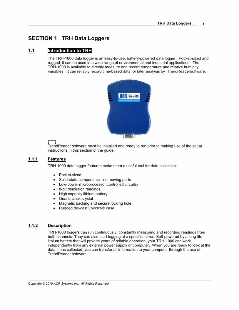
1.1 Introduction to TRHThe TRH-1000 data logger is an easy-to-use, battery-powered data logger. Pocket-sized andrugged, it can be used in a wide range of environmental and industrial applications. TheTRH-1000 is available to directly measure and record temperature and relative humidityvariables. It can reliably record time-based data for later analysis by TrendReadersoftware.
[****]TrendReader software must be installed and ready to run prior to making use of the setupinstructions in this section of the guide.
1.1.1 FeaturesTRH-1000 data logger features make them a useful tool for data collection:
· Pocket-sized· Solid-state components - no moving parts· Low-power microprocessor controlled circuitry· 8-bit resolution readings· High capacity lithium battery· Quartz clock crystal· Magnetic backing and secure locking hole· Rugged die-cast Cycoloy® case
1.1.2 DescriptionTRH-1000 loggers can run continuously, constantly measuring and recording readings fromboth channels. They can also start logging at a specified time. Self-powered by a long-lifelithium battery that will provide years of reliable operation, your TRH-1000 can workindependently from any external power supply or computer. When you are ready to look at thedata it has collected, you can transfer all information to your computer through the use of TrendReader software.
TRH Data Loggers2
Copyright © 2010 ACR Systems Inc. All Rights Reserved.
Main ComponentsThe main components of the TRH-1000 data loggers include:
· a memory chip that has the capacity to store up to 32,640 readings (see Specifications)
· a microprocessor and an 8-bit analog-to-digital converter (A/D) that converts alltemperature and relative humdity signals to digital values
· a quartz clock crystal that accurately keeps track of time and regulates the taking ofreadings
· a lithium battery that provides power to the logger and internal sensors
1.1.3 Programmed OperationTRH-1000 data loggers run according to settings that you program. These pre-selectedsettings are stored in the logger's memory and instruct it to:
· take readings at regularly spaced intervals· take readings from both channels· associate each channel with an equation in TrendReader software· start readings with or without a delay· take readings continuously, or stop when memory is full
1.1.4 How TRH Loggers Take ReadingsEach TRH-1000 data logger has an on-board temperature and relative humidity sensor thatyou can use to record ambient temperature and relative humidity.
TRH-1000 data loggers can store readings to memory using one of two sampling methods:
1. First-in, First-out (FIFO). In this method the logger continues to take readings when itsmemory is full (to make room, it discards the oldest reading every time it adds a newone). Thus, the memory will contain a "sliding window" of information.
2. Stop when Full. The logger stops recording when its memory is full.
You can set the time interval at which your logger saves readings using TrendReadersoftware. The sample rate you select will apply to both channels. At a sample rate of eightseconds, one reading is taken from both channels every eight seconds and saved to memory. TRH-1000 data loggers can store readings using one of two sampling modes:
1. Average. As you slow the sample rate the logger begins to average readings beforesaving them to memory. To do this the logger takes a reading every eight seconds, butinstead of transferring this directly to the logger's memory, it stores the readings in anaccumulator (a temporary memory) where it is retained until the sampling interval isover. Then the accumulator is averaged and the result is stored to memory.
2. Spot. The logger records the value of the reading at the selected sample interval andstores it to memory. No averaging is done.
When you backup a logger's data to your computer, the correct time and date are referenced

TRH Data Loggers 3
Copyright © 2010 ACR Systems Inc. All Rights Reserved.
to each reading. All readings are then individually time and date stamped and processed byan equation associated with each logger channel. The result is a collection of accuratetime-based data ready for detailed graphing and analysis.
1.1.5 How to Use TRH LoggersUsing your TRH-1000 data logger for most applications is a simple process. With properplanning, setup and installation of your data logger, you can be assured that the informationyou collect will be both correct and useful. The following provides general procedures for usingTRH-1000 data loggers. For additional and specific information on these steps, refer to thechapter in this manual.
PlanningProper planning is the key to successful data logging. Time spent in this stage will help yousave time and frustration later. To help you plan, answer these questions:
· What exactly do I want to measure?· Where is the best place to measure?· How long do I want to monitor for?· Should other variables be monitored simultaneously?
SetupTo set up your TRH-1000 data logger you must first have TrendReader software installed andrunning on your computer. You can then configure your logger with various options by talkingto it via the interface cable.
Set Sample RateAlways confirm the sample rate (how often the logger saves readings) to make sure it will beacceptable for your application. You can alter the frequency at which your TRH-1000 loggerrecords readings by changing the sample rate. You can choose rates from 8 seconds to 34minutes. The sample rate chosen will apply to all the active channels on the logger.
To help determine which sample rate you should choose, answer these questions:
· How long do I need to record data?· How much time will elapse between when I retrieve the logger and download the data to
my computer (for example, the trip back to the office)?· How often do readings need to be taken?
Clear MemoryBefore starting a logging session, clear the logger's memory. This will help to keep thecollected files smaller as well as decrease the time needed to backup the logger later. Notethat clearing the memory is automatic if you save or apply the setup changes (for example,assign different equations, change sample rate, etc.).
TestYou can directly read the values that your TRH-1000 data logger is sensing using the Realtimecapability of TrendReader software. This test gives you the opportunity to check your logger

TRH Data Loggers4
Copyright © 2010 ACR Systems Inc. All Rights Reserved.
setup and make any necessary changes before starting the logging session.
LabelIf you are working with more than one data logger, label each logger, identifying the task andlocation before you distribute them throughout a building or system. To do this, you can simplyuse a shipping tag. Later, when you retrieve them to graph their data, you will know what eachgraph refers to. There is a description field in the Setup that can be used for entering the taginformation. Note that after editing and saving the Description you will need to click Contact toupdate the new Description in TrendReader Explorer and in the Diagnostic Log.
MountingUse the magnetic backing to conveniently mount your logger on metal surfaces like ductworkor electrical control cabinets. If you are concerned about theft lock your logger to a permanentfixture using the security loop or take advantage of its small size and hide it completely out ofview. Because TRH-1000 loggers are so light, you can use special mounting fasteners likeVelcro® to attach them to almost any surface. Make sure your logger's mounting method willlast the full length of your logging session.
Do not rely on the logger's magnetic strip for adhesion if the mounting surface is uneven,unstable or above 65°C (150°F).
Cold or Humid EnvironmentsMake sure that the environment you will be placing your logger into will be acceptable byreferring to the Specifications in this chapter. If conditions are not adequate for the logger,consider using a protective enclosure. For humid conditions you can protect your loggersimply by placing it in a zip-lock plastic bag. Note that covering the logger may affect therelative humidity readings.
When you place your TRH-1000 logger in a cold environment, make sure condensation willnot settle on the logger when you bring it back into warmer surroundings, such as an office. The best way of preventing moisture is to place the logger in a container and include adesiccant (a material that absorbs moisture). When you bring your logger back to yourcomputer, leave the logger in the container until it has had a chance to warm up to thesurrounding temperature. You can then take it out and backup the data to be analyzed.
Keep TrackMake sure you keep a record of where you have placed each logger in a building or systemplan. You will save time looking for them when your data gathering session is over. Also,keep track of when you placed the loggers in the area you are monitoring. This will help whenproducing graphs on your computer. It may be helpful to label (shipping tag) each logger soyou can properly identify and differentiate it from other loggers.
AnalysisAfter sufficient time has passed for the logger to obtain a representative profile of data, it istime to analyze the information. If you are retrieving the logger from the field, bring it backimmediately to your computer for analysis.
In order to analyze your TRH-1000 logger's data, you must first transfer a backup copy of itsdata to your computer. To do this, see Backup in the TrendReader guide. After transferringyour information to the computer, the data is automatically copied to disk and time and date

TRH Data Loggers 5
Copyright © 2010 ACR Systems Inc. All Rights Reserved.
stamped.
You can find a detailed description of all software functions in the TrendReader guide.
1.1.6 SpecificationsGeneralSize: 25.4 mm x 58.4 mm x 81.3 mm (1" x 2.3" x 3.2")
Weight: 74 g (2.6 oz)
Enclosure Material: Cycoloy® (GE Plastics) C120 ABS + Polycarbonate
Mounting: Magnetic backing and security loop
Operating Limits: -40 to 70°C (-40 to 158°F) and 0 to 100% Relative Humidity(non-condensing)
Clock Accuracy: ±2 seconds/day
Battery: 3.6 Volt Lithium, 1 Amp-hour
Battery Life: 5 years under normal use (factory replaceable)
Memory Size: 64KB (up to 32,640 readings per channel)
Memory Usage: 1. Continuous (First-in, First-out)2. Stop when full (Fill-then-stop)
Sample Intervals: User-selectable rates from every 8 seconds to 34 minutes.
Sampling Mode: 1. Average (over sample interval except for 8 secondinterval)2. Spot
Resolution: 8-bit (1 part in 256)
Internal Temperature SensorType: CMOSens® (by Sensiron)
Range: -40 to 70°C (-40 to 158°F)
Accuracy: ± 0.6°C @ 25°C (± 1.0°F @ 77°F)± 2.0°C from -40 to 70°C (± 3.6°F from -40 to 158°F)
Calibration: Factory calibration verification and NIST certificates areavailable upon special request.
Equation: Use Equation [91] TRH 1000 Temperature in TrendReadersoftware. Other equations for this thermistor type may beselected but will give incorrect results. You may also createyour own equations, please refer to the Equations section orcontact Customer Service at ACR Systems.

TRH Data Loggers6
Copyright © 2010 ACR Systems Inc. All Rights Reserved.
Internal Relative Humiduty SensorType: CMOSens® (by Sensiron)
Range: 0 to 100% RH (non-condensing)
Accuracy: ± 4% RH between 20 and 80% RH; otherwise ± 5% RH
Equation: Use Equation [92] TRH 1000 Relative Humidity inTrendReader software
Specifications are subject to change without notice.
1.1.7 Product ApprovalsCertified to CE standard EN61326: 1977 + A1: 1998 (European Emissions and Immunity)covering ESD, RFI, EFT /B, Surge, Conducted Immunity, and Voltage Dips and Interruptions
Meets FCC standard 47 CFR Part 15, Subpart B: 1999, Class B, (US Radiated and ConductedEmissions)
TRH-1001:UL-913 Class-I, Div-1 (intrinsically safe rating)

TRH Data Loggers 7
Copyright © 2010 ACR Systems Inc. All Rights Reserved.
1.2 TRH Software DriverTrendReader software uses a software driver to communicate with TRH-1000 data loggers.The software driver takes the form of two windows. The Status window, shown when youcontact the logger, is used to display the settings currently stored in the data logger. TheSetup window, shown when you select Edit Setup, is used to alter the current settings andapply the changes to the data logger. The settings are divided into two main sections: Statusand Channels. Status contains information about sampling, memory and logger description.Each channel of the logger contains information about the channel type (temperature orrelative humidity), equation, Realtime value, and calibration associated with the channel. Youcan control the level of detail that you see for the settings by clicking on the "+" and "-" buttonsat the left side to expand and collapse the nodes.
When you want to clear the logger's memory and start a new logging session with the existingor new parameters, select Edit Setup from TrendReader. In the Edit Logger Setup window,make any necessary changes. To implement your changes, you can either click on Apply orOK. OK will implement the changes and close the window whereas Apply will leave thewindow open, thereby allowing you to make changes in other features.
1.2.1 Logger StatusWhen you contact the logger, the logger status is displayed. The Status line indicates whetherthe data logger is actively logging, waiting to start or dormant. If you set up the logger with nodelay, it will immediately start logging. The status will show if the logger is actively logging,dormant or set to start at a given time. It will also show the status of the logger's capacity. The Status subsections are Sampling and Memory.
1.2.1.1 Logger SamplingThe sample rate is the frequency with which a logger stores readings to memory. TheSampling subsection indicates what the sample rate is. The rates available are from onceevery 8 seconds to once every 34 minutes.
To set the sample rate, click on the desired time unit and select the value from the drop-downlist as shown.

TRH Data Loggers8
Copyright © 2010 ACR Systems Inc. All Rights Reserved.
To find out more about sample rates and to view a set of sample rate tables, see Appendix ASample Rates.
The Mode is the way the logger stores the data. The Average method stores an averagedreading of the data read every 8 seconds over the sample interval you have chosen if thesampling mode is set to Average (this does not apply to a sampling interval of 8 seconds). TheSpot method still takes readings every 8 seconds but only stores the reading taken at theselected interval.
1.2.1.2 Logger MemoryThe Memory subsection indicates how the data is stored in memory and what the start andend times (or capacity) are for the data logging. In the FIFO (First In, First Out) mode, thelogger continually stores data and when the memory limit is reached, the new readings start tooverwrite the oldest readings. In this method, the logger is always collecting data, but onlysaves the most recent data in its memory. In the Stop When Full mode, when the memorylimit is reached, the logger stops recording.
The length of time for data capture of the logger is determined by the number of activechannels and the sampling rate. To find out more about how the capacity is affected by thesample rate and active channels, see Appendix A Sample Rates.
To set how the logger stores its data, click on the Usage field and select FIFO or Stop When

TRH Data Loggers 9
Copyright © 2010 ACR Systems Inc. All Rights Reserved.
Full.
Currently there is no compression method available for TRH-1000 loggers.
To set when the logger will start recording click on the Start Time field. Next, click on thesmall button that appears at the right. This will pop up a form allowing you to set the date andtime. Highlight the date or time and enter the appropriate value. You can also click on thedrop-down list arrow to bring up a calendar. You can set the logger's starting time for justover 65535*8 seconds (6 days, 1 hour, 38 minutes) ahead of the current time. Note that thestart time will default to the closest time sampling within 8 seconds of the selected time.
TRH Data Loggers10
Copyright © 2010 ACR Systems Inc. All Rights Reserved.
1.2.2 Logger ChannelsThe Channels section provides information specific to each channel. Both channels on alogger are always enabled, they are active and continually record readings and store them inthe logger's memory. The Channel subsections are Channel Information and ChannelCalibration.
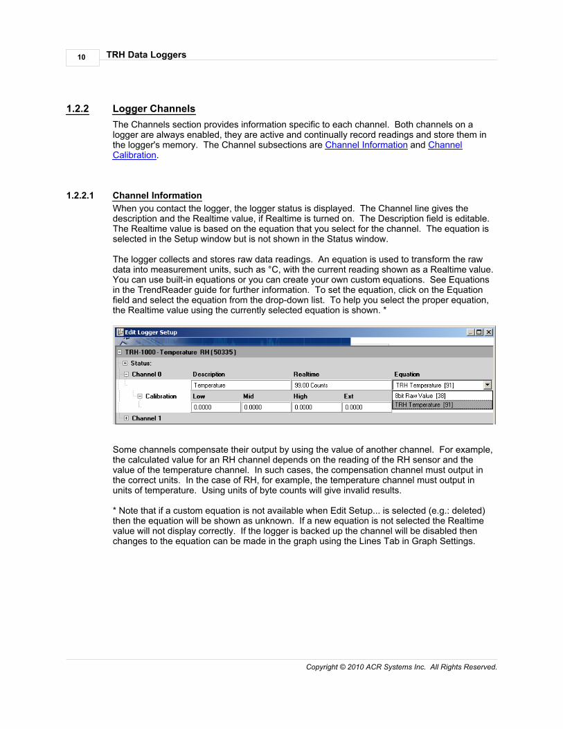
1.2.2.1 Channel InformationWhen you contact the logger, the logger status is displayed. The Channel line gives thedescription and the Realtime value, if Realtime is turned on. The Description field is editable. The Realtime value is based on the equation that you select for the channel. The equation isselected in the Setup window but is not shown in the Status window.
The logger collects and stores raw data readings. An equation is used to transform the rawdata into measurement units, such as °C, with the current reading shown as a Realtime value.You can use built-in equations or you can create your own custom equations. See Equationsin the TrendReader guide for further information. To set the equation, click on the Equationfield and select the equation from the drop-down list. To help you select the proper equation,the Realtime value using the currently selected equation is shown. *
Some channels compensate their output by using the value of another channel. For example,the calculated value for an RH channel depends on the reading of the RH sensor and thevalue of the temperature channel. In such cases, the compensation channel must output inthe correct units. In the case of RH, for example, the temperature channel must output inunits of temperature. Using units of byte counts will give invalid results.
* Note that if a custom equation is not available when Edit Setup... is selected (e.g.: deleted)then the equation will be shown as unknown. If a new equation is not selected the Realtimevalue will not display correctly. If the logger is backed up the channel will be disabled thenchanges to the equation can be made in the graph using the Lines Tab in Graph Settings.

TRH Data Loggers 11
Copyright © 2010 ACR Systems Inc. All Rights Reserved.
1.2.2.2 Channel CalibrationThe Calibration subsection shows the Low, Mid, High, and Ext calibration values. Thesevalues are used to adjust the readings of the logger in order to make the output moreaccurate. To set each calibration value, click on the appropriate calibration field and enter thevalue. The factory equations for the TRH-1000 use the Low and Mid values as offset andspan. High and Ext are not used.
Note that the calibration values are based on 255 increments between -5 and +5, the field willdefault to the closest value of what is entered. E.g.: -4.9 will default to -4.8828125.

TRH Data Loggers12
Copyright © 2010 ACR Systems Inc. All Rights Reserved.
1.3 TRH-1000 Temperature & Relative Humidity LoggerA self-contained "air-quality" logger, the TRH-1000 can be used easily in a wide variety ofapplications to collect temperature and relative humidity data.
1.3.1 DescriptionThe TRH-1000 is a low-cost, easy-to-use temperature and relative humidity data logger. Withits precision calibrated internal temperature and relative humidity sensor, simply place thelogger in the field and leave it to record. Once the desired information has been recorded, plugthe logger into the serial port of your computer and begin downloading and viewing the loggeddata with TrendReader software. No cables, wires or accessories are required, making theTRH-1000 the ideal data logger for quick and accurate temperature and humiditymeasurements in a variety of applications.
1.3.2 SetupOnce the logger is connected to your computer select the communications port inTrendReader and click Scan For Loggers.
Channel Description Equation0 Internal Temperature 911 Relative Humidity 92
NOTE: Both channels are enabled by default.
Precautions
The TRH-1000's sensor is designed for long-term trouble-free performance, but there are afew precautions to keep in mind to maximize the benefit it can give you.
· Never expose the sensor to organic solvents or ionic-laden liquids. Any chemicalcompound that attracts polymers may affect the sensor.
· Always return the TRH-1000 to a resealable plastic bag during non-use to maximize thein-calibration life of the RH sensor.
TRH Data Loggers 13
Copyright © 2010 ACR Systems Inc. All Rights Reserved.
1.3.3 TroubleshootingIf you are getting what appear to be wrong readings, consider the following before recalibratingthe sensors. Sensors sample the atmosphere (or medium) only in the immediate vicinity ofthe sensors themselves. The physical state of the atmosphere and its degree of uniformityand turbulence will limit the validity of a measurement at some distance from the sensor. Thisbecomes especially apparent for the measurement of ambient temperature and relativehumidity.
In a room, temperature and RH levels may vary dramatically from location to location. Suchfactors as air stratification, drafts, and proximity to heat or humidity sources (people,equipment, moisture, solar gain, etc.) can contribute to a wide variance in conditions evenwithin a small, confined area. The individual sensors associated with your TRH-1000 measureand record temperature and RH only in one location. They do not, in any way, represent anoverall reading.
1.3.4 Relative Humidity CalibrationIf your TRH-1000 is supplied with a calibration certificate it will include calibration values.These calibration values must be entered in and stored in the logger. If your RH sensor is outof calibration check these values against the values in the logger to make sure they are thesame.
TRH Data Loggers14
Copyright © 2010 ACR Systems Inc. All Rights Reserved.
1.4 APPENDIX A TRH-1000 Sample Rates
TRH-1000 Sample Rates
1.4.1 How a Data Logger Stores ReadingsThe sample rate of your data logger is the frequency with which it stores readings in itsmemory. A selected sample will apply for all channels on a TRH-1000.
If you set your data logger's sample rate to eight seconds, it reads its input channels andstores the readings once every eight seconds. If you choose a sample rate longer than eightseconds, the logger still reads its input channels once every eight seconds, and stores anaveraged reading at the end of the sample interval you have chosen if the sampling mode isset to Average.
For example, if you use a two-minute sample rate, the data logger takes fifteen separatereadings over each two-minute interval. At the end of each two-minute interval, the loggercalculates the average of the fifteen readings, and stores that average in its memory.
Otherwise if the sampling mode is set to Spot the logger still takes readings every 8 secondsbut only stores the reading taken at the selected interval.
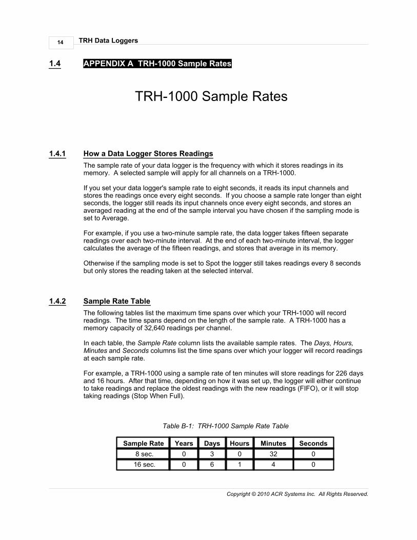
1.4.2 Sample Rate TableThe following tables list the maximum time spans over which your TRH-1000 will recordreadings. The time spans depend on the length of the sample rate. A TRH-1000 has amemory capacity of 32,640 readings per channel.
In each table, the Sample Rate column lists the available sample rates. The Days, Hours,Minutes and Seconds columns list the time spans over which your logger will record readingsat each sample rate.
For example, a TRH-1000 using a sample rate of ten minutes will store readings for 226 daysand 16 hours. After that time, depending on how it was set up, the logger will either continueto take readings and replace the oldest readings with the new readings (FIFO), or it will stoptaking readings (Stop When Full).
Table B-1: TRH-1000 Sample Rate Table
Sample Rate Years Days Hours Minutes Seconds 8 sec. 0 3 0 32 0 16 sec. 0 6 1 4 0

TRH Data Loggers 15
Copyright © 2010 ACR Systems Inc. All Rights Reserved.
32 sec. 0 12 2 8 0 56 sec. 0 21 3 44 0 2 min. 0 45 8 0 0
4 min. 56 sec. 0 111 19 44 0 10 min. 0 226 16 0 0 20 min. 1 87 36 0 0 30 min. 1 315 0 0 0

TRH Data Loggers16
Copyright © 2010 ACR Systems Inc. All Rights Reserved.
Index
- D -Data Logger 1
- L -Logger 1
- R -RH
Relative Humidity 12sensor 12
- S -Sample Rates 14
- T -Temperature 12TRH 1
Approvals 6Channel Calibration 11Channel Information 10Channels 10Description 1Features 1How to Use 3Memory 8Operation 2Readings 2Sampling 7Setup 7Software 7Specifications 5Status 7Unknown Equation 10
TRH-1000 12Approvals 6Data Logger 1Description 1Features 1How to Use 3Introductions 1Logger 1Operation 2Readings 2Specifications 5
TRH-1001 Approvals 6

