aco-4400 user manual - av-iqcdn-docs.av-iq.com/other/aco-4400_manual.pdfaco-4400 user manual (iss....
TRANSCRIPT

ACO-4400Automatic Changeover System for the SRG-4400
User Manual
Thank you for choosing RossYou've made a great choice. We expect you will be very happy with your purchase of Ross Technology.
Our mission is to:
1. Provide a Superior Customer Experience
• offer the best product quality and support
2. Make Cool Practical Technology
• develop great products that customers love
Ross has become well known for the Ross Video Code of Ethics. It guides our interactions and empowers our employees. I hope you enjoy reading it below.
If anything at all with your Ross experience does not live up to your expectations be sure to reach out to us at [email protected].
David RossCEO, Ross [email protected]
Ross Video Code of Ethics
Any company is the sum total of the people that make things happen. At Ross, our employees are a special group. Our employees truly care about doing a great job and delivering a high quality customer experience every day. This code of ethics hangs on the wall of all Ross Video locations to guide our behavior:
1. We will always act in our customers’ best interest.
2. We will do our best to understand our customers’ requirements.
3. We will not ship crap.
4. We will be great to work with.
5. We will do something extra for our customers, as an apology, when something big goes wrong and it's our fault.
6. We will keep our promises.
7. We will treat the competition with respect.
8. We will cooperate with and help other friendly companies.
9. We will go above and beyond in times of crisis. If there's no one to authorize the required action in times of company or customer crisis - do what you know in your heart is right. (You may rent helicopters if necessary.)

ACO-4400 User Manual• Ross Part Number: 4400DR-004B-01
• Release Date: July 2, 2014.
Copyright
© 2014 Ross Video Limited. Ross®, openGear®, and any related marks are trademarks or registered trademarks of Ross Video Ltd. All other trademarks are the property of their respective companies. PATENTS ISSUED and PENDING. All rights reserved. No part of this publication may be reproduced, stored in a retrieval system, or transmitted in any form or by any means, mechanical, photocopying, recording or otherwise, without the prior written permission of Ross Video. While every precaution has been taken in the preparation of this document, Ross Video assumes no responsibility for errors or omissions. Neither is any liability assumed for damages resulting from the use of the information contained herein.
Patents
Patent numbers 4,205,346; 5,115,314; 5,280,346; 5,561,404; 7,034,886; 7,508,455; 7,602,446; 7,834,886; 7,914,332; 8,499,019 B2; 2039277; 1237518; 1127289 and other patents pending.
Important Regulatory and Safety Notices to Service PersonnelBefore using this product and nay associated equipment, refer to the “Important Safety Instructions” listed below to avoid personnel injury and to prevent product damage.
Product may require specific equipment, and/or installation procedures to be carried out to satisfy certain regulatory compliance requirements. Notices have been included in this publication to call attention to these specific requirements.
Symbol Meanings
Important Safety Instructions
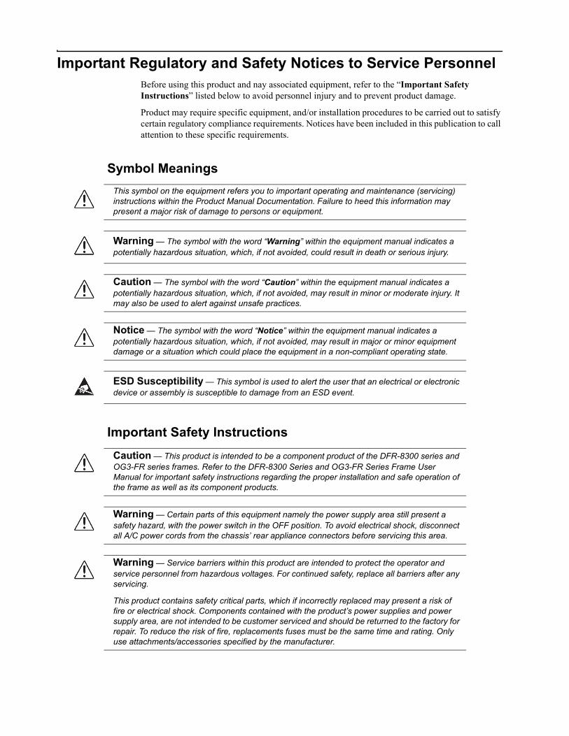
This symbol on the equipment refers you to important operating and maintenance (servicing) instructions within the Product Manual Documentation. Failure to heed this information may present a major risk of damage to persons or equipment.
Warning — The symbol with the word “Warning” within the equipment manual indicates a potentially hazardous situation, which, if not avoided, could result in death or serious injury.
Caution — The symbol with the word “Caution” within the equipment manual indicates a potentially hazardous situation, which, if not avoided, may result in minor or moderate injury. It may also be used to alert against unsafe practices.
Notice — The symbol with the word “Notice” within the equipment manual indicates a potentially hazardous situation, which, if not avoided, may result in major or minor equipment damage or a situation which could place the equipment in a non-compliant operating state.
ESD Susceptibility — This symbol is used to alert the user that an electrical or electronic device or assembly is susceptible to damage from an ESD event.
Caution — This product is intended to be a component product of the DFR-8300 series and OG3-FR series frames. Refer to the DFR-8300 Series and OG3-FR Series Frame User Manual for important safety instructions regarding the proper installation and safe operation of the frame as well as its component products.
Warning — Certain parts of this equipment namely the power supply area still present a safety hazard, with the power switch in the OFF position. To avoid electrical shock, disconnect all A/C power cords from the chassis’ rear appliance connectors before servicing this area.
Warning — Service barriers within this product are intended to protect the operator and service personnel from hazardous voltages. For continued safety, replace all barriers after any servicing.
This product contains safety critical parts, which if incorrectly replaced may present a risk of fire or electrical shock. Components contained with the product’s power supplies and power supply area, are not intended to be customer serviced and should be returned to the factory for repair. To reduce the risk of fire, replacements fuses must be the same time and rating. Only use attachments/accessories specified by the manufacturer.
EMC Notices
United States of AmericaFCC Part 15
This equipment has been tested and found to comply with the limits for a class A Digital device, pursuant to part 15 of the FCC Rules. These limits are designed to provide reasonable protection against harmful interference when the equipment is operated in a commercial environment. This equipment generates, uses, and can radiate radio frequency energy and, if not installed and used in accordance with the instruction manual, may cause harmful interference to radio communications. Operation of this equipment in a residential area is likely to cause harmful interference in which case the user will be required to correct the interference at their own expense.
CANADA
This Class “A” digital apparatus complies with Canadian ICES-003.
Cet appariel numerique de la classe “A” est conforme a la norme NMB-003 du Canada.
EUROPE
This equipment is in compliance with the essential requirements and other relevant provisions of CE Directive 93/68/EEC.
INTERNATIONAL
This equipment has been tested to CISPR 22:2009 and found to comply with the limits for a Class A Digital device.
Maintenance/User Serviceable Parts
Routine maintenance to this Ross Video product is not required. This product contains no user serviceable parts. If the module does not appear to be working properly, please contact Technical Support using the numbers listed under the “Contact Us” section on the last page of this manual. This Ross Video product is covered by a generous 5-year warranty and will be repaired without charge for materials or labor within this period. See the “Warranty and Repair Policy” section in this manual for details.
Notice — Changes or modifications to this equipment not expressly approved by Ross Video Limited could void the user’s authority to operate this equipment.
Notice — This is a Class A product. In domestic environments, this product may cause radio interference, in which case the user may have to take adequate measures.

Environmental Information
The equipment that you purchased required the extraction and use of natural resources for its production. It may contain hazardous substances that could impact health and the environment.
To avoid the potential release of those substances into the environment and to diminish the need for the extraction of natural resources, Ross Video encourages you to use the appropriate take-back systems. These systems will reuse or recycle most of the materials from your end-of-life equipment in an environmentally friendly and health conscious manner.
The crossed out wheelie bin symbol invites you to use these systems.
If you need more information on the collection, re-use, and recycling systems, please contact your local or regional waste administration.
You can also contact Ross Video for more information on the environmental performance of our products.

Company Address
Ross Video Limited Ross Video Incorporated
8 John Street P.O. Box 880
Iroquois, Ontario, K0E 1K0 Ogdensburg, New York
Canada USA 13669-0880
General Business Office: (+1) 613 • 652 • 4886
Fax: (+1) 613 • 652 • 4425
Technical Support: (+1) 613 • 652 • 4886
After Hours Emergency: (+1) 613 • 349 • 0006
E-mail (Technical Support): [email protected]
E-mail (General Information): [email protected]
Website: http://www.rossvideo.com


Contents
Introduction 1
Overview.............................................................................................................................. 1-2Functional Block Diagram................................................................................................... 1-4Documentation Terms and Conventions.............................................................................. 1-5
Before You Begin 2
Before You Begin ................................................................................................................ 2-2Static Discharge..................................................................................................... 2-2Unpacking.............................................................................................................. 2-2
Initial Product Inspection..................................................................................................... 2-3Operating Environment Requirements ................................................................................ 2-4Rack Mount Installation....................................................................................................... 2-5
Installing the ACO-4400 into a Rack Unit ............................................................ 2-5Installing the Rear Support Brackets..................................................................... 2-5
Connecting Power................................................................................................................ 2-6Replacing a Power Supply..................................................................................... 2-6
Accessories and Options...................................................................................................... 2-8User Documentation.............................................................................................. 2-8Power Cords .......................................................................................................... 2-8
Installation 3
Required Equipment ............................................................................................................ 3-2Functional Check Procedure and First Time Operation ...................................................... 3-3Initial Power-Up .................................................................................................................. 3-4Initial Configuration ............................................................................................................ 3-6Performing Functional Checks ............................................................................................ 3-7
Normal Operation (No Faults)............................................................................... 3-7Loss of the Primary Signal .................................................................................... 3-7Loss of Power ........................................................................................................ 3-8
Operational Configuration ................................................................................................... 3-9Power..................................................................................................................... 3-9Signals ................................................................................................................... 3-9
Operating Basics 4
Front Panel Overview .......................................................................................................... 4-2Rear Panel Overview ........................................................................................................... 4-3Operating Basics .................................................................................................................. 4-5
Operating Mode..................................................................................................... 4-5Fault Reporting...................................................................................................... 4-5
Software Field Upgrade ....................................................................................................... 4-6Uploading the Software Files ................................................................................ 4-6
Menu System 5
Menu Screens and Maps ...................................................................................................... 5-2
ACO-4400 User Manual (Iss. 01) Contents • i

Main Menu ........................................................................................................................... 5-5Operational Mode .................................................................................................. 5-5Output .................................................................................................................... 5-5Other Menus .......................................................................................................... 5-5
Signal Strength Menu........................................................................................................... 5-6Channel # = POK X BOK X.................................................................................. 5-6
Channel Configuration Menu............................................................................................... 5-8Installation Scenarios............................................................................................. 5-8Channel # Type...................................................................................................... 5-8
System Menus .................................................................................................................... 5-10Temperature Reports ........................................................................................... 5-10System Report...................................................................................................... 5-12
Configuration Menu ........................................................................................................... 5-14LCD Brightness ................................................................................................... 5-14Number of Channels ............................................................................................ 5-14
Network Menu ................................................................................................................... 5-15DashBoard Menu ............................................................................................................... 5-17
Port....................................................................................................................... 5-17Calibration Menu ............................................................................................................... 5-18
Changeover Channel............................................................................................ 5-18 Do Calibration?................................................................................................... 5-18P NSig, B NSig .................................................................................................... 5-19
Specifications 6
General Characteristics ........................................................................................................ 6-2Performance Conditions ........................................................................................ 6-2
BNC Channels ..................................................................................................................... 6-3Balanced (Unmonitored Channels, Relay Changeover) ...................................................... 6-4RS-232 Interface .................................................................................................................. 6-5Ethernet Interface ................................................................................................................. 6-6AC Power Source................................................................................................................. 6-7Physical Specifications......................................................................................................... 6-8
Clearance ............................................................................................................... 6-8Mechanical Characteristics .................................................................................... 6-8 Environment Characteristics................................................................................. 6-8
Connector Pinouts 7
Balanced Connector ............................................................................................................. 7-2Pin Views of Chassis Connectors .......................................................................... 7-3
RS232 Connector ................................................................................................................. 7-4Connector Pinouts.................................................................................................. 7-4Breakout Cable ...................................................................................................... 7-4Pin Views of Chassis Connectors .......................................................................... 7-5
Balanced Signals Interface Cable 8
Balanced Changeover Channels 1-8 .................................................................................... 8-2Balanced Changeover Channels 9-16 .................................................................................. 8-3
Calibration Procedure 9
Overview .............................................................................................................................. 9-2Calibrating the ACO-4400 ................................................................................................... 9-3
ii • Contents ACO-4400 User Manual (Iss. 01)

Service Information 10
User Maintenance .............................................................................................................. 10-2General Care........................................................................................................ 10-2Exterior Cleaning................................................................................................. 10-2Preventive Maintenance ...................................................................................... 10-2Servicing.............................................................................................................. 10-3Service Safety Overview ..................................................................................... 10-3Important Information ......................................................................................... 10-3
Troubleshooting Checklist ................................................................................................. 10-4Warranty and Repair Policy............................................................................................... 10-5
ACO-4400 User Manual (Iss. 01) Contents • iii

iv • Contents ACO-4400 User Manual (Iss. 01)

Introduction
In This ChapterThis chapter contains the following sections:
• Overview
• Functional Block Diagram
• Documentation Terms and Conventions
A Word of Thanks
Congratulations on choosing a Ross Video ACO-4400 Automatic Changeover System for your SRG-4400. Your ACO-4400 is part of the Ross Video family of products, backed by Ross Video’s experience in engineering and design expertise since 1974.
You will be pleased at how easily your new ACO-4400 fits into your overall working environment. Equally pleasing is the product quality, reliability and functionality. Thank you for joining the group of worldwide satisfied Ross Video customers!
Should you have a question pertaining to the installation or operation of your ACO-4400, please contact us at the numbers listed on the back cover of this manual. Our technical support staff is always available for consultation, training, or service.
ACO-4400 User Manual (Iss. 01) Introduction • 1–1
OverviewThe ACO-4400 is designed for high reliability Master Sync operations where two SRG-4400 units are provided as a fail-safe Primary and Backup pair. The ACO-4400 provides automatic fail over to the wide range of SRG-4400 reference signals.
The ACO-4400 provides user-selection of reference sources. Automatic changeover may occur upon fault detection in any active source.
The ACO-4400 is an in-line device without internal buffers. Switching for all channels is by mechanical relay. The ACO-4400 also provides internal termination for unswitched BNC inputs.
The ACO-4400 includes 12 channels in a 1U rack. Each BNC channel consists of a Primary Input, a Backup Input, and an Output. All BNC channel relays switch in unison upon fault detection in any active BNC channel, front-panel command, or remote command.
In conjunction with the BNC channels, there are a number of unmonitored “slave” channels available on multi-way connectors. Each multi-way connector channel consists of a Primary Input, a Backup Input, and an Output. All multi-way connector channel relays switch in unison upon fault detection in any active BNC channel, front-panel command, or remote command.
The ACO-4400 uses signal amplitude as the basis for error checking. You can configure each BNC channel to check for a different type of input. There is a selection of predefined checking levels relating to the various signals that are supported:
• No Measurement
• Color Black (no ancillary signals present, i.e. only Sync and Burst)
• Color Black + VITC (with one or some ancillary signals present)
• 600mV Tri Sync
• SD SDI - LOS
• HD SDI - LOS
• 3G SDI - LOS
• 1V 10MHz
• 1V Sub-carrier
• 1V AES
• 2V Pulses - LOS
• 4V Pulses - LOS
For the common signals, a fault is reported when the input signal level falls below a predetermined ratio of the nominal peak value. Visual fault indications appear on the front-panel display for signals from both the Primary and Backup SRG-4400s. These indications remain on until cleared by the operator.
For other signals, a simple “Loss Of Signal” (LOS) detection is performed.
The signal reference amplitudes used for fault detection are programmed during factory calibration. The ACO-4400 includes a dual PSU, which provides power supply failure redundancy.
1–2 • Introduction ACO-4400 User Manual (Iss. 01)

Features
The ACO-4400 includes the following key features:
• 12 channels in 1U rack height
• All BNC channels are signal agnostic
• All BNC channels are measured on both Primary and Backup inputs
• Ethernet (100-BaseT) interface remote control
• No fans
• All Configuration settings performed through DashBoard
• Tight integration with SRG-4400
ACO-4400 User Manual (Iss. 01) Introduction • 1–3

Functional Block DiagramThis section provides the functional block diagram that outlines the workflow of the ACO-4400.
Figure 1.1 ACO-4400 — Functional Diagram
*Including unmonitored multi-way channels
BACKUPPEAK
DETECT
PRIMARYPEAK
DETECT
PRIMARYLEVELCHECK
BACKUPLEVELCHECK
Output
Primary Input
Secondary Input
RELAY
OTHER CHANNELS
OTHER CHANNELS
OTHER CHANNELS
LOGICDECODE
Other Channel Relays*
Operating Status/Fault Indications
Auto / Manual
Primary / BackupLCD
DISPLAY
REFERENCEGENERATORS
1–4 • Introduction ACO-4400 User Manual (Iss. 01)

Documentation Terms and ConventionsThe following terms and conventions are used throughout this manual.
Terms
The following terms are used:
• “Operator” and “User” refer to the person who uses ACO-4400.
• “System” and “Video system” refer to the mix of interconnected production and terminal equipment in your environment.
Conventions
The following conventions are used:
• The “Operating Tips” and “Note” boxes are used throughout this manual to provide additional user information.
ACO-4400 User Manual (Iss. 01) Introduction • 1–5

1–6 • Introduction ACO-4400 User Manual (Iss. 01)

Before You Begin
In This ChapterThis chapter provides instructions for installing the ACO-4400.
The following topics are discussed:
• Before You Begin
• Initial Product Inspection
• Operating Environment Requirements
• Rack Mount Installation
• Connecting Power
• Accessories and Options
ACO-4400 User Manual (Iss. 01) Before You Begin • 2–1

Before You BeginBefore installing the ACO-4400, refer to the section “Important Regulatory and Safety Notices to Service Personnel” located at the front of this manual for power source, grounding, and other general safety information.
Static Discharge
Throughout this manual, please heed the following cautionary note:
Unpacking
Unpack each ACO-4400 you received from the shipping container and ensure that all items are included. If any items are missing or damaged, contact your sales representative or Ross Video directly.
ESD Susceptibility — Static discharge can cause serious damage to sensitive semiconductor devices. Avoid handling in high static environments such as carpeted areas and when synthetic fiber clothing is worn. Always exercise proper grounding precautions when working on circuit boards and related equipment.
2–2 • Before You Begin ACO-4400 User Manual (Iss. 01)

Initial Product InspectionPerform the following Initial Product Inspection Procedure when you receive your ACO-4400:
1. Inspect the shipping carton for external damage, which may indicate possible damage to the ACO-4400. If damage exists, document it, including photographs, to support any insurance claim.
2. Remove the instrument from the shipping carton.
3. Check that the ACO-4400 has not been damaged in transit. The exterior should not have any scratches or impact marks. Prior to shipment the ACO-4400 is thoroughly inspected for mechanical defects.
4. Verify that the shipping carton contains the instrument, the standard accessories, and any optional accessories that you ordered.
5. Perform the Functional Check Procedure as outlined in the section “Required Equipment” on page 3-2 after installing the ACO-4400.
Note — Save the shipping carton and packaging materials for ACO-4400 replacement re-packaging in case return shipment becomes necessary.
ACO-4400 User Manual (Iss. 01) Before You Begin • 2–3

Operating Environment RequirementsVerify that the location of your installation has the proper operating environment. The ACO-4400 operates correctly in ambient temperatures from 0 °C to +40 °C and relative humidity from 20% to 80%.
For More Information on...
• environmental operating specifications, refer to the appendix “Specifications” on page 6-1.
The ACO-4400 requires 2” (50mm) of side clearance for counter top use. Also, ensure sufficient rear clearance, e.g. 3” (75mm), so that cables are not compromised.
The ACO-4400 does not currently have an internal fan to assist with ventilation or cooling. Therefore, when you install the unit in an equipment bay, it is imperative that you ensure there is sufficient space all around the unit to allow the airflow to vent away any excess heat generated by the unit.
Caution — The ACO-4400 could be damaged if it is powered on at temperatures or humidities outside the specified ranges.
2–4 • Before You Begin ACO-4400 User Manual (Iss. 01)

Rack Mount InstallationYou can install the ACO-4400 into an equipment rack. It is recommended to loom the cables so that they do not introduce extra weight or twisting force on the front panel rack mountings or rear panel connectors. If installed in a mobile application, the rack mount kit is essential.
This section describes how to install the ACO-4400 into the rack.
Installing the ACO-4400 into a Rack Unit
The ACO-4400 mounts in the rack cabinet by means of four screws through the front mounting flanges. This should normally be sufficient to carry the load, including weight of cables. Refer to the SRG-4400 Quick Start Guide for mounting details.
Installing the Rear Support Brackets
In some cases, (mobile trucks, etc.) it may be desirable to also support the rear of the ACO-4400. The rear support bars can be attached to the ACO-4400 in six possible positions. (Figure 2.1)
Figure 2.1 Installing the Support Brackets
To install the support brackets
1. Choose the position that suits the cabinet depth and will give approximately a 0.5” projection beyond the previously mounted bracket.
2. Using four screws per bracket, as shown in Figure 2.1, attach both bars.
3. Mount the frame to the front rails of the rack cabinet using rack screws.
4. At the rear of the cabinet, slide the bracket slots over the rear of the support bars and secure to the cabinet rear rails with rack screws.
Warning — To prevent the rack mounted ACO-4400 from tipping forward onto the operator, install the instrument so that the operator will be able to access all of its rear-panel connectors without pushing down on the instrument.
Warning — Do not use the support brackets to carry the ACO-4400. The brackets are not primarily designed for this purpose, and property damage or personal injury may result.
One Rack-Unit (1RU)Mounting Frame
Side View
Rack CabinetRear View
CabinetFront VerticalMounting Rail
CabinetRear VerticalMounting Rail
CabinetLeft Rear Vertical
Mounting Rail
CabinetRight Rear Vertical
Mounting Rail
0.500”
Rear Support Bar
Bracket
Allow approximately 0.500” of the end of theRear Support Bar to project beyond the Bracket
Select a mounting positionthat allows Rear Support Barsto slide into slots of Brackets
ACO-4400 User Manual (Iss. 01) Before You Begin • 2–5

Connecting PowerThe ACO-4400 operates from a single-phase power source with the neutral conductor at or near earth ground. The line conductor is fused for over-current protection. A protective ground connection through the grounding conductor in the power cord is essential for safe operation. Safety earth studs are also provided for earth bonding the chassis if you so require.
You need to provide two power connections. For full power security, these should be on separate, independent and secure power grids. However, you still gain the security of power supply failure redundancy if you use the same power grid for both connections.
AC Power Requirement
Check that your location provides the proper electrical power requirements as listed in Table 2.1.
Connecting the Power Cable
Connect the power cable to the instrument first, and then connect it to the AC power source. Note that connecting a live power cable causes the instrument to power on.
Replacing a Power Supply
If you need to replace a power supply, you must remove the faceplate from the chassis to gain access to the power supplies. This section summarizes how to replace a power supply in your ACO-4400.
To replace a power supply
1. Remove the four front screws from the control panel faceplate.
Figure 2.2 Removing the Faceplate Screws
2. Remove the faceplate by gently pulling it towards you and away from the chassis. The screws are self-retained in their holes.
Table 2.1 AC Line Power Requirement
Parameter Description
Line Voltage Range 100-240V
Line Frequency 50/60Hz
Maximum Power (Dual PSU) 46VA (21W)
Caution — The ACO-4400 does not have a power switch.
ACO-4400 AUTO CHNG
2–6 • Before You Begin ACO-4400 User Manual (Iss. 01)

Figure 2.3 Removing the Faceplate
3. Each power supply includes two screws that must be removed before the power supply can be removed from the chassis. Refer to Figure 2.4 for the screw locations on each power supply.
Figure 2.4 Screw Locations on Each Power Supply
4. Remove a power supply by gently pulling it towards you and away from the chassis.
Figure 2.5 Removing the Power Supplies from the Chassis
5. Install the new power supply as follows:
a) Sliding the new power supply into the available slot.
b) Secure the power supply into its slot via the provided screws.
3. Position the faceplate over the power supplies.
4. Secure the faceplate on the chassis using the provided screws.
Figure 2.6 Re-installing the Faceplate
ACO-4400 AUTO CHNG
ACO-4400 AUTO CHNG
ACO-4400 User Manual (Iss. 01) Before You Begin • 2–7
Accessories and OptionsThe following accessories are shipped with the ACO-4400.
User Documentation
A Documents disk is included with your ACO-4400.
Power Cords
All ACO-4400 are shipped with one of the following power cord options:
• Power cords for use in the United Kingdom are BS1363 approved.
• Power cords for use in North America are UL listed and CSA certified.
• Power cords for use in Europe conform to CEE7, DIN49441 and VDE standards.
• Cords for use in other areas are approved by at least one authority acceptable in the country to which the product is shipped.
2–8 • Before You Begin ACO-4400 User Manual (Iss. 01)

Installation
In This ChapterPerform the following procedures if you are operating the ACO-4400 for the first time (to verify that the ACO-4400 shipped without damage), or you suspect that the ACO-4400 is not working properly.
The following topics are discussed:
• Required Equipment
• Functional Check Procedure and First Time Operation
• Initial Power-Up
• Initial Configuration
• Performing Functional Checks
• Operational Configuration
ACO-4400 User Manual (Iss. 01) Installation • 3–1

Required EquipmentThe following equipment is required for the functional check:
• Video Test Signal Generator
• Waveform / Picture Monitors (multi-format)
• 75ohm BNC cables
• Breakout cable/box for the rear panel 30-way multi-way connector (optional/not supplied)
3–2 • Installation ACO-4400 User Manual (Iss. 01)

Functional Check Procedure and First Time OperationThese procedures will guide you through the steps required to check the operation of the ACO-4400. The most common scenarios will be explored to enable the user to familiarize themselves with the operation of the unit. Although some steps are included which suggest cycling through menu options in order to check operation, this is not mandatory - a simple check for presence or absence of a signal will suffice. Full details regarding the options available in each of the menus are described in the chapter “Menu System” on page 5-1 of this manual. The scenarios to be explored are:
1. Initial Power-Up
2. Initial Configuration
3. Normal Operation (no fault)
4. Loss and Restoration of a Primary Signal
5. Loss and Restoration of a Backup Signal
6. Loss and Restoration of Power
Only one channel will be considered here to avoid confusion. To check the whole unit, repeat this procedure for each of the remaining channels, remembering to leave signals connected to previously checked channels.
Because the un-monitored channels (on the 30-pin multi-way connectors) are “slaves” to the BNC channels, no specific details are listed in this procedure regarding their function. Simply connect suitable signals to the relevant connector pins, and monitor the signal changeovers happening at the same time as the BNC channels listed in the procedure below.
ACO-4400 User Manual (Iss. 01) Installation • 3–3

Initial Power-Up1. Ensure that the ACO-4400 is not powered on.
2. Connect the ACO-4400 as shown in Figure 3.1. Ensure that the ACO-4400 output is properly terminated at the monitoring device.
Figure 3.1 Functional Check Connections
3. Apply power to the ACO-4400 by connecting it to the power source(s). The instrument runs its power-on initialization process.
4. Check that no error messages appear on the LCD display. You may see a message that relates to missing inputs. This will be because the ACO-4400 is configured to monitor more channels than you currently have signals connected. If you are sure that you want to cancel the message and continue with the procedure, press the Rotary Control once
5. Much of the functional check can be carried out immediately. However, some calibration settings are only guaranteed once functional temperature has stabilized (which should occur after 20 minutes). It is good practice to soak the instrument before proceeding.
Note — The signal inputs are nominally different in order to easily verify which signal is switched to the output.
GPI/RS232
100-BaseT
— 7 —BACKUP PRIMARY BACKUP
BACKUP — 2 —
— 8 — PRIMARY BACKUP — 9 — PRIMARY BACKUP — 10 — PRIMARY BACKUP — 11 — PRIMARY BACKUP — 12 — PRIMARY
BACKUP — 1 — PRIMARY PRIMARY BACKUP BACKUP BACKUP BACKUP— 3 — — 4 — — 5 — — 6 —PRIMARY PRIMARY PRIMARY PRIMARY
BALANCED
BALANCED
TV SIGNAL GENERATOR
WAVEFORM MONITOR
Composite VideoAnalog Color Black
3–4 • Installation ACO-4400 User Manual (Iss. 01)

6. Selecting or editing Menu items requires you to turn the Rotary Control in order to select or change the highlighted Menu item / setting, then to press the Rotary Control to select or confirm that Menu item / setting.
• Pressing the Rotary Control will either select the highlighted Menu item for editing, exit Menu item editing, or take you to the next Menu level.
• Note that there may be more Menu lines available than can be displayed on the LCD screen or video outputs; be sure to scroll down (or up) to find the required entry.
7. Pressing the blue dedicated push-button once will exit the current Menu level or item.
• When you have finished editing the Menu options, you should press the blue dedicated push-button to exit the Menu system completely.
• You need to press the button a suitable number of times to get back to the stand-by screen (the one with the “Ross Video” logo, one press “up” from the “Top Level” Menu) - this will save any changes that you have made to the non-volatile memory.
ACO-4400 User Manual (Iss. 01) Installation • 3–5

Initial ConfigurationThe ACO-4400 should arrive configured to a “factory default” condition, i.e. all channels set for Type = Color Black, Operational Mode = Automatic, Output = Primary.
To ensure that you have a suitable channel configuration for the purposes of this Functional Check, you should perform the following procedures.
To select the number of active channels
1. Verify that you are in the “Top Level” menu: “ACO-4400”.
2. Select < - System Setup >.
3. [Confirm]
4. Select the System Menu.
5. Highlight < - Configuration >.
6. [Confirm]
7. Highlight < Number of channels >.
8. [Confirm]
9. Set the number of channels. For initial configuration, select 1 channel.
10. [Confirm]
11. Select [Back] twice to return to the “Top Level” menu.
To select the channel type(s)
1. Verify that you are in the “Top Level” menu: “ACO-4400“.
2. Highlight < -Channel Setup >.
3. [Confirm]
4. Select the Channel Configuration Menu.
5. Highlight the channel to change. For initial configuration, select Channel 1.
6. [Confirm]
7. Select the channel type. For initial configuration, select Color Black.
8. [Confirm]
9. Select [Back] to return to the “Top Level” menu.
Note — [Confirm] indicates that you should press the Rotary Control, and [Back] indicates that you should press the blue push-button.
3–6 • Installation ACO-4400 User Manual (Iss. 01)

Performing Functional ChecksNote that in the following procedures, some intermediate instructions relating to cursor movements and control button presses are omitted for clarity.
Normal Operation (No Faults)
From the “Top Level” menu:
1. Check / Set “Operational Mode” = < Auto >. This is the default at power-up if no faults are detected.
2. Check / Set “Output” = < Primary >. This is the default at power-up if no faults are detected).
3. You should see that the channel output is the Primary input signal (Composite Video).
4. Select “Operational Mode” = < Manual >. Select “Output” = < Backup >. The channel output switches to the Backup input signal (Analog Color Black).
5. Select “Output” = < Primary >. The channel output switches to the Primary input signal (Composite Video).
6. Select “Operational Mode” = < Auto >.
Loss of the Primary Signal
From the “Top Level” menu:
1. Press the [Back] button once to enter the Stand-By screen - “Ross Video” Logo.
2. Disconnect the Primary input signal (Composite Video).
3. Re-connect the Primary input signal (Composite Video). Note that the fault indication changes to show that the Primary input signal is now correct, and the channel output automatically switches back to the Primary input signal (Composite Video).
4. Press [Confirm] to clear the fault indication.
5. Select “Operational Mode” = < Manual >.
6. Press [Back] to go to the Stand-By screen.
7. Disconnect the Primary input signal (Composite Video). Note that no switching occurs, but that the Primary fault indication appears.
8. Press [Confirm] to clear the fault indication.
9. Select “Output” = < Backup >. The channel output switches to the Backup signal (Analog Color Black).
10. Re-connect the Primary input signal (Composite Video).
Note — You cannot select “Output = Backup” when the Operational Mode is set to “Auto”.
Note — The channel output automatically switches to the Backup input signal (Analog Color Black), and a fault indication appears on the display.
ACO-4400 User Manual (Iss. 01) Installation • 3–7

11. Select “Output” = < Primary >. The channel output switches to the Primary input signal (Composite Video).
12. Select “Operational Mode” = < Auto >.
Loss of Power
1. Turn off the power to one of the mains inlets. The associated fault indication appears in the display.
2. Restore power to the mains inlet. The fault indication changes to show that the “fault” is fixed.
3. Turn off the power to the other mains inlet. The associated fault indication appears in the display.
4. Restore power to the mains inlet. The fault indication changes to show that the “fault” is fixed.
5. Turn off the power to both mains inlets. The channel output changes to the Primary input signal (Composite Video) and the unit powers down.
3–8 • Installation ACO-4400 User Manual (Iss. 01)

Operational ConfigurationThere are several configuration factors that will influence the initial installation of your ACO-4400. The following guidelines outline a typical example.
Power
The ACO-4400 will automatically switch to the Primary inputs whenever it loses power. So, you should connect the Backup SRG-4400 and one mains input on the ACO-4400 to the same power source, and connect the Primary SRG-4400 (and the second mains input on the ACO-4400) to a second power source. In these configurations, both power connections would have to fail before you lose control of the ACO-4400.
Signals
You should now configure the ACO-4400 according to your requirements, namely the number of channels to be monitored, and the signal type associated with each channel (using the procedures detailed in the previous Initial Configuration section of this manual). When finished, remember to exit the Menu system properly to save your settings in non-volatile memory.
When selecting the number of channels, you must always start from number 1, and continue up to the number of signals you wish to monitor. You should set any unused channels to “No Measurement”. If you select more active channels than you have signals connected, “Input Missing” errors will always be reported, leading to inconsistent operation.
You can now connect your signals to the ACO-4400 rear panel BNCs (Figure 3.1 as an example), according to the configuration settings made in the previous paragraph. The example in Figure 3.1 shows six channels from the list of supported signal types but does not illustrate multi-way channels. Note that the maximum is 12 channels.
Figure 3.2 Example of ACO-4400 Connections
ACO-4400
PrimarySRG-4400
Primary 1
Backup 1
Primary 2
Backup 2
Primary 3
Backup 3
Primary 4
Backup 4
Primary 5
Backup 5
Primary 6
Backup 6
SRG-4400
ACO-4400 User Manual (Iss. 01) Installation • 3–9

You should produce a master reference sheet, in order to log how each channel is configured and connected (an example is shown below in Table 3.1). This will be helpful to refer to in the future in order to quickly find out whether, for example, a previously unused channel requires a menu change relating to the new signal to be monitored.
Table 3.1 ACO-4400 Channel Configuration
Channel Channel Type Signal Attached
1
2
3
4
5
6
7
8
9
10
11
12
3–10 • Installation ACO-4400 User Manual (Iss. 01)

Operating Basics
In This ChapterThis chapter outlines the basics of operating the ACO-4400.
The following topics are discussed:
• Front Panel Overview
• Rear Panel Overview
• Operating Basics
• Software Field Upgrade
ACO-4400 User Manual (Iss. 01) Operating Basics • 4–1

Front Panel OverviewFigure 4.1 shows the ACO-4400 Front Panel. Descriptions of the Front Panel controls and indicators appear below.
Figure 4.1 ACO-4400 — Front Panel
1. LCD Display
The dot-matrix LCD display is used to show system status, fault indications, and general in-use information, as well as being used to configure the Menu system items.
2. Back Button
The Back push-button is used to exit the current Menu screen, and to traverse back through the Menus, ultimately to the stand-by screen.
Pressing the dedicated push-button once will exit the current Menu level. When you have finished editing the Menu options, you should use the dedicated push-button to exit the Menu system completely. You need to press the button a suitable number of times to get back to the stand-by screen (the one with the “Ross” logo, one press “up” from the top level Menu) - this will save any changes that you have made to the non-volatile memory.
3. Rotary / Push Control
The Rotary / Push control has two functions:
• the rotary function is used to navigate up or down items in a Menu, or to cycle through a range of values relating to a Menu item,
• the push function is used to confirm a Menu item selection for editing, to exit Menu item editing, or take you “forward” to the next Menu item.
Selecting or editing Menu items requires you to turn the Rotary Control in order to select or change the highlighted Menu item / setting, then to press the Rotary Control to select or confirm that Menu item / setting. Pressing the Rotary Control will select the highlighted Menu item for editing, exit Menu item editing, or take you to the next Menu level. Note that there may be more Menu lines available than can be displayed on the LCD screen; be sure to scroll down (or up) to find the required entry.
4. Removable Power Supplies (Not Shown)
There are two Removable Power Supply assemblies, installed and secured into the front of the ACO-4400, either side of the LCD display. These units can be “hot swapped”, i.e. they can be removed or inserted while mains power is still present. Should it become necessary to replace one or both of the Removable Power Supply assemblies, the instrument does not have to be removed from the rack.
ACO-4400 AUTO CHNG
1
2
3
4–2 • Operating Basics ACO-4400 User Manual (Iss. 01)

Rear Panel OverviewFigure 4.2 shows the ACO-4400 Rear Panel. Descriptions of the rear-panel connectors appear on the following pages.
Figure 4.2 ACO-4400 — Rear Panel
1. Power Connectors
The ACO-4400 is designed to operate from a single-phase power source with the neutral conductor at or near earth ground. The line conductor is fused for over-current protection. A protective ground connection through the grounding conductor in the power cord is essential for safe operation. Safety earth studs are also provided for earth bonding the chassis if you so require.
The ACO-4400 operates from an AC line frequency of 48Hz to 63Hz, over the range of 85VAC to 250VAC, without the need for user configuration. Refer to the chapter “Specifications” on page 6-1 for additional information on power and environment requirements.
You need to provide two power connections, one for each power supply. For full power security, these should be on separate, independent and secure power grids. However, you still gain the security of power supply failure redundancy if you use the same power grid for both connections.
2. BALANCED Connectors
Two 30-pin multi-way connectors are present. These are unmonitored relay changeover channels that follow the BNC channels. Typical signals to connect here are those not supported via the BNC channels, such as Balanced Audio, Balanced Timecode, or single-ended signals, etc.
3. BACKUP - # - PRIMARY BNCs
Each triplet of BNCs relates to one changeover channel, comprising of a Primary input, a Backup input, and an output.
• BACKUP — An input from the Backup SRG-4400 is connected here. The signal applied must be the same format as the Primary.
• # — The switched output from either the Primary input or the Backup input appears on the centre BNC of each triplet. Which input appears here, and when, is determined by the configuration of the unit.
• PRIMARY — An input from the Primary SRG-4400 is connected here. The signal can be any one of the supported types. The signal applied must be the same format as the Backup. If the channel is configured for “No Measurement”, almost any signal may be connected (the user must take into account, and be aware of, the limitations of the switching relay regarding voltage, current and signal bandwidth).
4. GPI / RS232
This rear-panel connector is a 10-pin male dual-in-line type. This allows for RS-232 communication, and GPI/O functionality. This port is not implemented.
Warning — To avoid the risk of electric shock, do not operate the unit when the top cover is removed. Dangerous high voltages are present within the unit.
GPI/RS232
100-BaseT
— 7 —BACKUP PRIMARY BACKUP
BACKUP — 2 —
— 8 — PRIMARY BACKUP — 9 — PRIMARY BACKUP — 10 — PRIMARY BACKUP — 11 — PRIMARY BACKUP — 12 — PRIMARY
BACKUP — 1 — PRIMARY PRIMARY BACKUP BACKUP BACKUP BACKUP— 3 — — 4 — — 5 — — 6 —PRIMARY PRIMARY PRIMARY PRIMARY
BALANCED
BALANCED
1 152 3
4
ACO-4400 User Manual (Iss. 01) Operating Basics • 4–3

5. 100-Base T
This rear-panel connector is a standard RJ45 Ethernet connector. This is used for DashBoard communication. After installation, it may be used to upload software updates.
4–4 • Operating Basics ACO-4400 User Manual (Iss. 01)

Operating BasicsThe ACO-4400 can be thought of as an automatic multi-pole switch that actuates whenever an error is detected in any BNC signal channel. All channels will switch at the same time.
Any unused BNC input channel should be configured to disable error checking. If unused channels are not disabled, they will always produce error signals leading to improper operation.
Error threshold levels are pre-defined during initial testing, and are not adjustable.
Operating Mode
The ACO-4400 can be operated in one of two modes, selected from within the menu system. The options are either Automatic or Manual control. When “Auto” is selected, the ACO-4400 will automatically switch if a fault is detected. When “Manual” is selected, the ACO-4400 will switch only when the operator manually selects between Primary and Backup.
Fault Reporting
There is an LCD indication for fault reporting on all channels. If a fault occurs in one of the configured channels on either the Primary or Backup input, the LCD indicator will illuminate to report the fault. The fault reporting is persistent, i.e. even if the fault is only an intermittent one, the fault indicator will stay illuminated. If more than one fault exists, only the “first” one is reported, i.e. counting from the lowest numbered configured channel. As faults are repaired, the fault indicator displays the next faulty input/channel in the list, etc. Repairing the last fault will update the LCD display to show that the [last] fault has been fixed - clearing the fault indication will turn the LCD fault indication off.
ACO-4400 User Manual (Iss. 01) Operating Basics • 4–5

Software Field UpgradeThis upgrade procedure outlines the steps necessary to upgrade the software programmed on the ACO-4400.
Before starting, ensure that you comply with the following requirements:
• Connect the ACO-4400 via an Ethernet cable to your local network;
• A PC, also connected via Ethernet to your local network, with the supplied update program(s) and associated data file(s) available - ideally, data file(s) should be located in the same folder as the associated update program;
• A power-cycle is required as part of a data file update - ensure that the unit is not in service during the update process.
• Ensure that you have the Application Image software. Application Image files are prefixed with “ArmFile”. Usually a load address and software version will be appended, e.g. “ArmFile_<load_address>_<software-version>.ata”.
• Requires that the ACO-4400 is in Boot Load mode. When complete, a power re-boot is required.
Uploading the Software Files
To upload software files to a ACO-4400, the ACO-4400 needs to be in Boot Lode mode.
1. Set the ACO-4400 in Boot Lode mode as follows:
• Power down the unit.
• Hold down the blue push button on the front panel.
• Apply power to the unit.
• After 5 seconds, the LCD screen should confirm that the ACO-4400 is in Boot Lode Mode.
• Release the button.
2. On your PC, run the “RossSystemUpdate_v#.#.#.#.exe” program.
3. In the dialog boxes, enter the IP address and IP Mask for the ACO-4400.
4. Select the [Get Device Mode] button. The status dialog should confirm the mode: “The device is in Boot Load mode.” confirmation displays in the dialog.
5. If the ACO-4400 is “not found”, check again that all connections have been made and that the IP addresses have been entered correctly, then try repeating the above procedure after turning the ACO-4400 OFF, and then restarting the System Update program.
6. If the ACO-4400 still cannot be found, contact Ross Video for further assistance.
7. Select the [Open File] button.
8. Select the relevant “ *.ATA” file.
9. Select the [Send to device] button. Upload of file takes approximately 1 minute.
10. The status messages window should confirm that the upload was completed successfully. If not, select [Send to device] again.
11. Power Cycle the ACO-4400.
Your ACO-4400 is now upgraded and ready for use.
4–6 • Operating Basics ACO-4400 User Manual (Iss. 01)

Menu System
In This ChapterThe ACO-4400 provides the user with a menu interface to control the functions and options of the instrument.
The following topics are discussed:
• Menu Screens and Maps
• Main Menu
• Signal Strength Menu
• Channel Configuration Menu
• System Menus
• Configuration Menu
• Network Menu
• DashBoard Menu
• Calibration Menu
ACO-4400 User Manual (Iss. 01) Menu System • 5–1

Menu Screens and MapsThe menus can always be viewed on the front panel LCD display. The menus are accessed from the initial start-up (Logo) screen by pressing the Back button or by pressing the rotary control. To return to the Logo screen, press the blue escape/back button. If you repeatedly press the blue button, the LCD display will cycle between the Logo screen and the top-level menu screen. Additional information is also included.
Logo Screen
In this display of logo, the additional information is:
• Device Name
• ACO-4400 IP Address (when connected)
• Software version number
By pressing the rotary control, you access the Top Level Menu. This menu gives you access to the three key menus that are used to control and configure the ACO-4400:
1. Signal Strength Menu
2. Channel Setup Menu
3. System Menu
Full details outlining how to use the front panel controls to navigate and change entries in the menus are given in the chapter “Operating Basics” on page 4-1. Figure 5.1 provides a quick reference of the menu system.
###.###.###.###
ACO-4400
v##
5–2 • Menu System ACO-4400 User Manual (Iss. 01)

Figure 5.1 ACO-4400 — Menu Map (Pictorial Example)
Chan 05 TypeChan 04 TypeChan 03 TypeChan 02 Type
No Measurement
Chan 01 Type
====
= Color BlackColor BlackColor BlackColor Black
— System— Channel Setup— Signal Strength
ACO-4400
—>—>—>
PrimaryOperational Mode
Menu EnterMenu EnterMenu EnterOutput = = Manual
— Network— Configuration— System Report— Event Report
—>—>—>—>
— Temp Report
Menu EnterMenu EnterMenu EnterMenu EnterMenu Enter —>
Fixed PSUUndefined1v2 Regulator3v3 Regulator
Sensor absentSensor absent
4545
Case Internal
4545
4545
Sensor absent
Ev 00008 NewMinTemp503.22.18.700.13Ev 00009 NewMinTemp503.22.21.255.13
April 2013
April 2013Ev 00010 Power On
Firmware v#Hardware v#
Software v#Bootware v#
Ethernet 100Mbps Full Duplex
Number of Channels 06LCD Brightness
== 040%
Port (fixed)Subnet MaskIP AddressDHCP (fixed)
xxxxxxxx.xxx.xxx.xxxxxx.xxx.xxx.xxx
Off== OffWebServer (fixed)
ACO-4400 User Manual (Iss. 01) Menu System • 5–3

Figure 5.2 is a basic menu tree structure of the ACO-4400.
Figure 5.2 ACO-4400 — Menu Map (Diagrammatic)
Signal Strength Screen
Channel Setup Menu
Logo Screen
Temp Report
Event Report
System Report
DashBoard
Calibration
Configuration
Network
System Menu
5–4 • Menu System ACO-4400 User Manual (Iss. 01)

Main MenuTable 5.3 provides an example of the Main Menu. The Main Menu is accessed by either pressing the escape button or the rotary control while viewing the “logo” stand-by screen.
Figure 5.3 Main Menu Example
Operational Mode
This menu line displays the current mode of operation of the ACO-4400. The options for the field are: Auto, Manual.
Auto
When set to Auto, fault detection is enabled, the outputs will automatically default to the Primary inputs, and, when applicable, automatic switching of inputs occurs when a fault is encountered:
When a Primary fault is repaired, the output will automatically switch back to the Primary input when the signal is re-connected (provided the signal conforms to that channel's configuration).
Manual
When set to Manual, fault detection is “disabled”, and the user is able to manually switch the output to be either the Primary or Backup input, irrespective of any existing faults.
Output
This menu line displays which of the inputs is currently switched to the output. The options for the field are: Primary, Backup. The user can only switch the output to Backup when the “Operational Mode” is set for “Manual”.
Other Menus
The Signal Strength Menu, Channel Setup Menu, and System Menu provide access to further menus or features, all of which are detailed in the following pages.
Table 5.1 Fault Actions
Fault on Switch
No fault Primary
Primary Backup
Backup Primary
Primary & Backup Backup
Audio Type Audio=—System —>Menu Enter—Channel Setup —>Menu Enter—Signal Strength —>Menu Enter
Primary Output =Operational ModeACO-4400
= Auto
ACO-4400 User Manual (Iss. 01) Menu System • 5–5
Signal Strength MenuFigure 5.4 provides an example of the Signal Strength Menu.
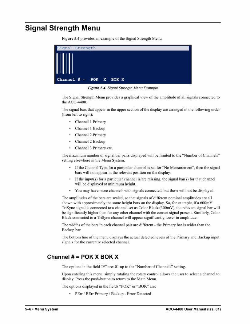
Figure 5.4 Signal Strength Menu Example
The Signal Strength Menu provides a graphical view of the amplitude of all signals connected to the ACO-4400.
The signal bars that appear in the upper section of the display are arranged in the following order (from left to right):
• Channel 1 Primary
• Channel 1 Backup
• Channel 2 Primary
• Channel 2 Backup
• Channel 3 Primary etc.
The maximum number of signal bar pairs displayed will be limited to the “Number of Channels” setting elsewhere in the Menu System.
• If the Channel Type for a particular channel is set for “No Measurement”, then the signal bars will not appear in the relevant position on the display.
• If the input(s) for a particular channel is/are missing, the signal bar(s) for that channel will be displayed at minimum height.
• You may have more channels with signals connected, but these will not be displayed.
The amplitudes of the bars are scaled, so that signals of different nominal amplitudes are all shown with approximately the same height bars on the display. So, for example, if a 600mV TriSync signal is connected to a channel set as Color Black (300mV), the relevant signal bar will be significantly higher than for any other channel with the correct signal present. Similarly, Color Black connected to a TriSync channel will appear significantly lower in amplitude.
The widths of the bars in each channel pair are different - the Primary bar is wider than the Backup bar.
The bottom line of the menu displays the actual detected levels of the Primary and Backup input signals for the currently selected channel.
Channel # = POK X BOK X
The options in the field “#” are: 01 up to the “Number of Channels” setting.
Upon entering this menu, simply rotating the rotary control allows the user to select a channel to display. Press the push-button to return to the Main Menu.
The options displayed in the fields “POK” or “BOK” are:
• PErr / BErr Primary / Backup - Error Detected
Channel # = POK X BOK X
5–6 • Menu System ACO-4400 User Manual (Iss. 01)

• POK / BOK Primary / Backup - No error detected.
The values displayed in the fields “X” represent the actual detected signal levels of the selected input channel.
ACO-4400 User Manual (Iss. 01) Menu System • 5–7

Channel Configuration MenuFigure 5.5 provides an example of the Channel Configuration menu.
Figure 5.5 Channel Configuration Menu Example
The Channel Configuration Menu allows the user to configure each BNC channel to monitor the incoming signal according to the selected signal type.
The number of channels displayed in this menu will be the same as that previously set in the menu item: Main Menu | System | Number of Channels. If there are more than 5 active channels, these are accessed by scrolling the menu downwards.
The menu displays the signal type to which each BNC channel is set to monitor. Each setting is selected from the list of supported signal types.
All input signals are detected for amplitude. Some signal types have pre-defined fault levels associated with them, and are used to determine whether an error has occurred. Other signal types have a simpler “Loss Of Signal” detection system. For the special case where signals are present but not required to be monitored for the purpose of errors, the “No Measurement” setting should be used.
Installation Scenarios
The most common scenario is one where a specific number of signals are required to be both monitored and switched. In this case, the “Number of Channels” setting will correspond with the same number of “Channel Configuration Menu” lines, all set to their relevant signal types.
Another scenario is one where more signals are required to be switched than monitored. On the ACO-4400, when a fault occurs, ALL channels switch, regardless of how many inputs are populated or configured. So, for this case, the user can either:
• select the 'additional' channel types as “No Measurement”, or,
• reduce the “Number of Channels” setting to correspond to the actual number of inputs to monitor, rather than the number of inputs connected.
Channel # Type
The options displayed in the field “#” are: 01 up to the “Number of Channels” setting.
Upon entering this menu, rotating the rotary control allows the user to select a channel to adjust. Pressing the rotary control allows the user to adjust the selected channel.
The options for the type are:
• No Measurement
• Color Black (no ancillary signals present, i.e. only Sync & Burst)
• Color Black + VITC (with one or some ancillary signals present)
Chan 05 Type No Measurement=Chan 06 Type No Measurement=
Chan 04 TypeChan 03 Type =
=
Chan 02 Type =Chan 01 Type = Color Black
SD SDI600mV Tri SyncNo Measurement
5–8 • Menu System ACO-4400 User Manual (Iss. 01)

• 600mV TriSync
• SD SDI - LOS
• HD SDI- LOS
• 3G SDI- LOS
• 1V 10MHz
• 1V Subcarrier
• 1V AES
• 2V Pulses- LOS
• 4V Pulses- LOS
After making your selection, press the rotary control to confirm the selection. Select additional channels to adjust.
When finished, press the push-button to return to the Main Menu.
ACO-4400 User Manual (Iss. 01) Menu System • 5–9

System MenusFigure 5.6 provides an example of the System Menu.
Figure 5.6 System Menu Example
The System Menu provides a gateway to the less frequently used options in the ACO-4400.
These options include:
• Extended information in the form of reports, Extended configuration options,
• Access to factory settings that the user should never have to access or adjust, but may contain useful information to communicate to the factory during a service event.
Temperature Reports
The Temperature Report appears below (general form).
Figure 5.7 Temperature Reports Menu Example
The Temperature Report provides information on the temperature sensors within the ACO-4400. A typical example might look like: “+3v3 Regulator 42 45 41 “
Depending on the exact configuration and options in the ACO-4400, one or more of the sensors might not be installed. In this case, the description in the relevant line appears as:
“Fixed PSU -Sensor absent”
Because the temperature report includes the current temperatures and both the minimum and maximum temperatures detected by the installed temperature sensors, this information might be useful if you are experiencing reliability problems in an extreme environment.
Note — Reports contain information only; there are no editable fields in these menus.
— Network —>Menu Enter— Calibration —>Menu Enter
— Configuration —>Menu Enter— System Report —>Menu Enter— Event Report —>Menu Enter— Temp Report Menu Enter —>
Undefined Sensor absent
Case Internal Sensor absent
+1v2 Regulator 4545 45+3v3 Regulator 4545 45
N+1 Interface 4545 45Fixed PSU 4545 45
5–10 • Menu System ACO-4400 User Manual (Iss. 01)
Event Report
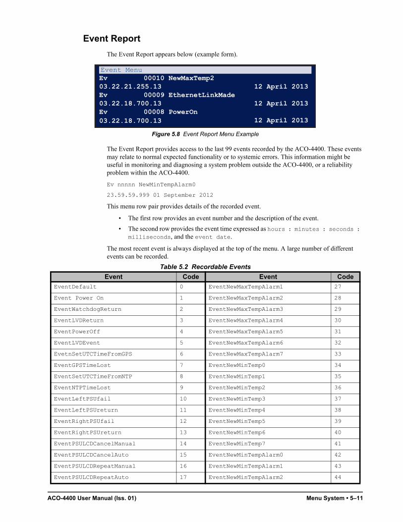
The Event Report appears below (example form).
Figure 5.8 Event Report Menu Example
The Event Report provides access to the last 99 events recorded by the ACO-4400. These events may relate to normal expected functionality or to systemic errors. This information might be useful in monitoring and diagnosing a system problem outside the ACO-4400, or a reliability problem within the ACO-4400.
Ev nnnnn NewMinTempAlarm0
23.59.59.999 01 September 2012
This menu row pair provides details of the recorded event.
• The first row provides an event number and the description of the event.
• The second row provides the event time expressed as hours : minutes : seconds : milliseconds, and the event date.
The most recent event is always displayed at the top of the menu. A large number of different events can be recorded.
Table 5.2 Recordable Events
Event Code Event Code
EventDefault 0 EventNewMaxTempAlarm1 27
Event Power On 1 EventNewMaxTempAlarm2 28
EventWatchdogReturn 2 EventNewMaxTempAlarm3 29
EventLVDReturn 3 EventNewMaxTempAlarm4 30
EventPowerOff 4 EventNewMaxTempAlarm5 31
EventLVDEvent 5 EventNewMaxTempAlarm6 32
EvetnSetUTCTimeFromGPS 6 EventNewMaxTempAlarm7 33
EventGPSTimeLost 7 EventNewMinTemp0 34
EventSetUTCTimeFromNTP 8 EventNewMinTemp1 35
EventNTPTimeLost 9 EventNewMinTemp2 36
EventLeftPSUfail 10 EventNewMinTemp3 37
EventLeftPSUreturn 11 EventNewMinTemp4 38
EventRightPSUfail 12 EventNewMinTemp5 39
EventRightPSUreturn 13 EventNewMinTemp6 40
EventPSULCDCancelManual 14 EventNewMinTemp7 41
EventPSULCDCancelAuto 15 EventNewMinTempAlarm0 42
EventPSULCDRepeatManual 16 EventNewMinTempAlarm1 43
EventPSULCDRepeatAuto 17 EventNewMinTempAlarm2 44
03.22.18.700.13 12 April 2013Ev 00008 PowerOn
12 April 201303.22.18.700.13Ev 00009 EthernetLinkMade
12 April 201303.22.21.255.13Ev 00010 NewMaxTemp2
ACO-4400 User Manual (Iss. 01) Menu System • 5–11

System Report
The System Report appears below.
Figure 5.9 System Report Menu Example
The System Report provides complete version information for the hardware, firmware and software elements that make up the ACO-4400.
ACO-4400 192.xxx.xxx.xxx
This field reports the user programmed Ethernet IP Address of the ACO-4400. The options in the sub-fields appear as: 0 through 255.
Ethernet Field
This field reports the detailed Ethernet link status. The options in the first sub-field appear as:
• <Blank>
• 10Mbps
• 100Mbps
The options in the second sub-field appear as:
• Full Duplex
• Half Duplex
Hardware and Firmware Fields
The Hardware field indicates the hardware version in use. This is not usually modified by field upgrades as it relates to the motherboard hardware components in the ACO-4400.
EventNewMaxTemp0 18 EventNewMinTempAlarm3 45
EventNewMaxTemp1 19 EventNewMinTempAlarm4 46
EventNewMaxTemp2 20 EventNewMinTempAlarm5 47
EventNewMaxTemp3 21 EventNewMinTempAlarm6 48
EventNewMaxTemp4 22 EventNewMinTempAlarm7 49
EventNewMaxTemp5 23 EventEthernetLinkMade 50
EventNewMaxTemp6 24 EventEthernetLinkLost 51
EventNewMaxTemp7 25 EventGPSSetTimecodeFromGPSFlag 52
EventNewMaxTempAlarm0 26 EventGPSUnSetTimecodeFromGPSFlag 53
Table 5.2 Recordable Events
Event Code Event Code
03.22.18.700.13 12April 2013Bootware vXXXX Software vXXXXHardware vXXXX Firmware vXXXX
Ethernet 100Mbps Full Duplex
5–12 • Menu System ACO-4400 User Manual (Iss. 01)

The Firmware field indicates the firmware version in use. This is not usually modified by field upgrades as it relates to the motherboard firmware components in the ACO-4400.
Bootware and Software Fields
The Bootware field indicates the bootware version in use. This is not usually modified by field upgrades as it relates to the motherboard bootware components in the ACO-4400.
The Software field indicates the software version in use. This can be modified in the field when new versions of the software are uploaded via the Ethernet interface.
ACO-4400 User Manual (Iss. 01) Menu System • 5–13
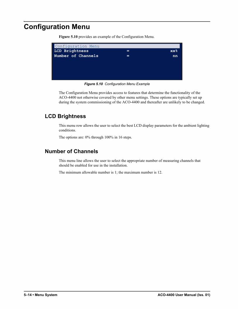
Configuration MenuFigure 5.10 provides an example of the Configuration Menu.
Figure 5.10 Configuration Menu Example
The Configuration Menu provides access to features that determine the functionality of the ACO-4400 not otherwise covered by other menu settings. These options are typically set up during the system commissioning of the ACO-4400 and thereafter are unlikely to be changed.
LCD Brightness
This menu row allows the user to select the best LCD display parameters for the ambient lighting conditions.
The options are: 0% through 100% in 16 steps.
Number of Channels
This menu line allows the user to select the appropriate number of measuring channels that should be enabled for use in the installation.
The minimum allowable number is 1; the maximum number is 12.
Number of Channels nn=LCD Brightness = xx%
5–14 • Menu System ACO-4400 User Manual (Iss. 01)

Network MenuFigure 5.11 provides an example of the Network Menu.
Figure 5.11 Network Menu Example
The Network Menu, and the associated sub-menus, allows the user to configure and control the behavior of the Ethernet system within the ACO-4400. Before proceeding, the user must contact their Network Administrator, and obtain suitable IP addresses, etc., that will need to be programmed within this menu.
IP Address
This menu line allows the user to enter the pre-determined IP address of the ACO-4400. The options in the sub-fields are: 000 through 255 where 000" is the default “no action” setting.
To change the settings:
1. pressing the rotary control advances through each sub-field
2. rotating the rotary control changes the value of the currently selected sub-field.
SubNet Mask
This menu line allows the user to enter the pre-determined SubNet Mask address of the ACO-4400.
The options in the sub-fields are: 000 through 255 where “000” is the default “no action” setting.
To change the settings:
1. pressing the rotary control advances through each sub-field
2. rotating the rotary control changes the value of the currently selected sub-field.
Gateway
This menu line allows the user to enter the pre-determined Gateway address of the ACO-4400. Typically, this might be the IP address of a network hub to which the ACO-4400 is connected.
The options in the sub-fields are: 000 through 255 where “000” is the default “no action” setting.
To change the settings:
1. pressing the rotary control advances through each sub-field
2. rotating the rotary control changes the value of the currently selected sub-field.
MAC Address
This menu line displays the MAC Address (Media Access Control), a unique, read-only identifier assigned to network interfaces for communications on the physical network segment.
MAC Address 00:00:00:00:00:00=
Subnet Mask 000.000.000.000=Gateway 000.000.000.000=
IP Address 000.000.000.000=
ACO-4400 User Manual (Iss. 01) Menu System • 5–15

This menu item cannot be changed - the MAC address is stored in a hardware device. This address is unique to each ACO-4400, and is also used to provide unique update keys when enabling options within the unit.
5–16 • Menu System ACO-4400 User Manual (Iss. 01)

DashBoard MenuFigure 5.12 provides and example of the Dashboard Menu.
Figure 5.12 DashBoard Menu Example
The DashBoard Menu displays information relating to communications between the ACO-4400 and the external PC-based Remote Control Program.
Port
This menu line allows the user to set the Ethernet Port through which the ACO-4400 communicates with the external PC-based Remote Control Program.
The options in the sub-field are: 5253 (default), and 6666.
Port = nnnn
ACO-4400 User Manual (Iss. 01) Menu System • 5–17

Calibration MenuFigure 5.13 provides an example of the Calibration Menu.
Figure 5.13 Calibration Menu Example
Disclaimer
The Calibration Menu contains fundamental settings relating to the functionality and accuracy of the ACO-4400. These settings are determined during initial testing and through subsequent configuration and alignment. They should not normally require re-configuration during service. It is a good idea to make a manual record of these settings in case they become corrupted or are inadvertently changed. A convenient way to achieve this is to print out the table at the end of this section, and record the stored values. You can then store this list in a safe place.
On no account should the user attempt to alter any of these settings without proper authorization from Ross Video Limited.
If problems are encountered, these settings can only be re-instated by performing the detailed Calibration Procedure. Contact Ross Video for further instructions.
Changeover Channel
This menu line allows the user to select the measuring channel to be viewed (or calibrated). The options in the field are: 1 through 12.
Do Calibration?
This menu line enables the user to start the calibration process at the channel number selected in the previous menu line.
The options in the field are:
• No — Calibration Disabled (Default)
• Yes — Calibration Enabled
This menu option is always set to “No” upon entry - it requires a conscious action on the part of the user to set the option to “Yes” and thereby enable calibration value adjustments.
When set to “No”, the user may view the calibration values for any channel at any time.
When set to “Yes”, the user is able to perform the calibration procedure to recalculate the calibration values, starting with the channel number selected above.
To exit from this menu, repeatedly press the [Back] button a sufficient number of times until you reach the “Top Level” menu screen.
P NSig=nnnn Sig=nnnn Fail-nnnnB NSig=nnnn Sig=nnnn Fail=nnnn
Do Calibration? Nonn
==Changeover Channel
5–18 • Menu System ACO-4400 User Manual (Iss. 01)

P NSig, B NSig
These menu lines display the stored calibration values for the selected channel number. The “P” menu line indicates that the line of calibration values is for the Primary channel.
Similarly, the “B” menu line indicates that the line of calibration values is for the Backup channel.
The “NSig=nnnn” sub-field displays the recorded value for the “no signal present and input terminated” condition.
The “Sig=nnnn” sub-field displays the recorded value for the level of the normal amplitude signal.
The “Fail=nnnn” sub-field displays the recorded value for the level of the reduced amplitude signal that will be used to determine whether the input signal is too low or has failed completely.
Table 5.3 Channel Calibration
ChannelPrimary Backup
NSig Sig Fail NSig Sig Fail
1
2
3
4
5
6
7
8
9
10
11
12
ACO-4400 User Manual (Iss. 01) Menu System • 5–19

5–20 • Menu System ACO-4400 User Manual (Iss. 01)

Specifications
In This ChapterThis chapter lists the electrical, mechanical, and environmental characteristics, as well as the national and international standards to which the ACO-4400 complies. Note that specifications are subject to change without notice.
The following topics are discussed:
• General Characteristics
• BNC Channels
• Balanced (Unmonitored Channels, Relay Changeover)
• RS-232 Interface
• Ethernet Interface
• AC Power Source
• Physical Specifications
ACO-4400 User Manual (Iss. 01) Specifications • 6–1
General CharacteristicsAll listed specifications are guaranteed unless labeled with “Typical”. Typical specifications are provided for your convenience, but are not guaranteed.
Performance Conditions
The electrical characteristics listed on the following pages are valid under the following conditions:
• The ACO-4400 must be in an environment where the temperature, altitude, humidity, and vibration conditions are within the operating limits described in the section “Balanced (Unmonitored Channels, Relay Changeover)” on page 6-4.
• The ACO-4400 must have a warm-up period of at least 20 minutes.
• The ACO-4400 must have been calibrated and adjusted at an ambient temperature between +20°C and +30°C.
6–2 • Specifications ACO-4400 User Manual (Iss. 01)

BNC Channels Table 6.1 BNC Channels
Category Performance Requirement Reference Information
Connector Type 3 x 75ohm BNC per channelThe unused input is automatically terminated
Return Loss (all inputs and outputs)
>20dB to 1GHz
>14dB to 3GHz
Insertion Loss (all inputs)
DC - 10MHz: < 0.02 dB
10MHz - 27MHz: 0.06 dB
27MHz - 1.5GHz: 0.35 dB
1.5GHz - 3GHz: 0.35 dB
Crosstalk> 60 dB to 1.5GHz
> 40 dB to 3GHz
Maximum Switched Voltage
30V DC (30V AC)
Maximum Switched Current
0.5A
Relay Switch Time
Based on Relay characteristics:
Set time: typ. 3.5 ms,
Release time: typ. 2.5 ms,
Set/Release: max. 10mS
Insertion Delay <1ns
ACO-4400 User Manual (Iss. 01) Specifications • 6–3

Balanced (Unmonitored Channels, Relay Changeover)
Table 6.2 Balanced (Unmonitored Channels)
Category Performance Requirement Reference Information
Connector Type Molex® MicroClasp™ 2mm, 30-pin
Return Loss> 17 dB to 50MHz
> 4 dB to 270MHz
Insertion LossDC - 270MHz: < 0.1 dB
270MHz - 1GHz: < 1.2 dB
Crosstalk
> 50 dB to 27MHz
> 25 dB to 270MHz
> 10 dB to 1GHz
Maximum Switched Voltage
48 V DC (24 V AC)
Maximum Switched Current
1 A
Relay Switch Time
Based on Relay characteristics:
Set time: max. 3 ms,
Release time: max. 2 ms,
Set/Release: min. 9mS.
Insertion Delay <1ns
6–4 • Specifications ACO-4400 User Manual (Iss. 01)

RS-232 Interface
Note — This port is not implemented.
Table 6.3 RS-232 Interface
Category Performance Requirement Reference Information
Connector Type Molex® MicroClasp™ 2mm, 30-pin
OutputsPin 2: GND
Pin 4: RS232 TX
Inputs Pin 3: RS232 RX
ACO-4400 User Manual (Iss. 01) Specifications • 6–5

Ethernet Interface
Table 6.4 Ethernet Interface
Category Performance Requirement Reference Information
Connector Type 1 x RJ45 - 8P8C
IEEE Standards Compliance
IEEE 802.31-1990 10BASE-T
IEEE 802.3u-1995 100BASE-TX
6–6 • Specifications ACO-4400 User Manual (Iss. 01)
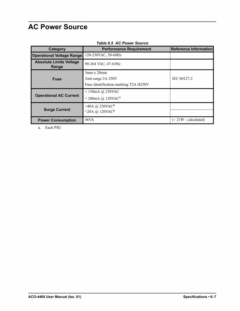
AC Power Source
Table 6.5 AC Power Source
Category Performance Requirement Reference Information
Operational Voltage Range 120-230VAC, 50-60Hz
Absolute Limits Voltage Range
90-264 VAC, 47-63Hz
Fuse
5mm x 20mm
Anti-surge 2A 250V
Fuse identification marking T2A H250V
IEC 60127-2
Operational AC Current< 130mA @ 230VAC
< 200mA @ 120VACa
a. Each PSU
Surge Current<40A @ 230VACa
<20A @ 120VACa
Power Consumption 46VA (~ 21W - calculated)
ACO-4400 User Manual (Iss. 01) Specifications • 6–7

Physical Specifications
Clearance
Mechanical Characteristics
Environment Characteristics
Table 6.6 Clearance
Category Performance Requirement Reference Information
ClearanceSide 50mm (2.00in)
Rear 75mm (3.00in)
Table 6.7 1Hz Frequency Reference Output
Category Performance Requirement Reference Information
Height 43.5 mm (1.71”)
Width 482.5 mm (19.00”)
Depth 405 mm (15.95”)
Net Weight 5.85 kg (12.9lbs)
Table 6.8 Environment Characteristics
Category Performance Requirement Reference Information
TemperatureOperating 0°C to +40°C
Non-operating -20°C to +60°C
Relative Humidity
Operating20% to 80% relative humidity (%RH) at up to +40°C, non-condensing
Non-operating5% to 90% relative humidity (%RH) at up to +60°C, non-condensing
AltitudeOperating To 2,000m (6,561ft)
Non-operating To 12,192m (40,000ft)
Vibration
Operating2.65m/s2 (0.27Grms), 5Hz to 500Hz, 10 minutes per axis, three axes
Non-operating22.3m/s2 (2.28Grms), 5Hz to 500Hz, 10 minutes per axes, three axes
ShockNon-operating 294m/s2 (30G), half-sine, 11ms
duration
6–8 • Specifications ACO-4400 User Manual (Iss. 01)

Connector Pinouts
In This ChapterThis chapter lists the pinouts of various multi-way connectors available on the rear panel of the ACO-4400 Note that specifications are subject to change without notice.
The following topics are discussed:
• Balanced Connector
• RS232 Connector
ACO-4400 User Manual (Iss. 01) Connector Pinouts • 7–1

Balanced ConnectorTable 7.1 provides the pinouts of various multi-way connectors available on the rear panel of the ACO-4400. Table 7.1 applies to both balanced connectors on the ACO-4400. These connectors are 30-pin, Molex™ 2mm micro-clasp.
Table 7.1 Balanced Pinouts
Pin Signal/Function
1 Ground
2 Ground
3 Ground
4 Channel 1 - Backup
5 Channel 1 - Common
6 Channel 1 - Primary
7 Channel 2 - Backup
8 Channel 2 - Common
9 Channel 2 - Primary
10 Channel 3 - Backup
11 Channel 3 - Common
12 Channel 3 - Primary
13 Channel 4 - Backup
14 Channel 4 - Common
15 Channel 4 - Primary
16 Channel 5 - Backup
17 Channel 5 - Common
18 Channel 5 - Primary
19 Channel 6 - Backup
20 Channel 6 - Common
21 Channel 6 - Primary
22 Channel 7 - Backup
23 Channel 7 - Common
24 Channel 7 - Primary
25 Channel 8 - Backup
26 Channel 8 - Common
27 Channel 8 - Primary
28 Ground
29 Ground
30 Ground
7–2 • Connector Pinouts ACO-4400 User Manual (Iss. 01)

Pin Views of Chassis Connectors
Connectors are Molex™ Micro Clasp 2mm series.
Figure 7.1 Chassis Connectors (Molex #55959-3030) Figure 7.2 Mating Connectors (Molex #51353-3000)
242830
132729
302
291
ACO-4400 User Manual (Iss. 01) Connector Pinouts • 7–3

RS232 Connector
Connector Pinouts
Table 7.2 provides the pinouts (Molex® 2mm MicroClasp™ series plug) for the GPI/RS232 connector. Refer to Table 6.3, for technical details regarding this connector.
Breakout Cable
Table 7.3 provides the pinouts for the GPI/RS232 breakout cable and can be used for the following connector types:
• 10-pin connector Molex® 2mm MicroClasp™ series socket (female)
• 9-pin connector, D-type, plug (male)
Note — This port is not implemented.
Table 7.2 GPI/RS232 Connector
Pin Signal/Function
1 Ground
2 Ground
3 RS232 - RX
4 RS232 - TX
5 GP Input 1 - TTL compatible
6 GP Input 2 - TTL compatible
7 GP Output 1 - Open Collector
8 GP Output 2 - Open Collector
9 ONAIR - Open Collector
10 Ground
Table 7.3 GPI/RS232 Breakout Cable
10-Pin Micro-clasp
Signal/FunctionD9 Plug (Male)
1 Ground n/c
2 Ground 5
3 RS232 - RX 2
4 RS232 - TX 3
5 GP Input 1 - TTL compatible n/c
6 GP Input 2 - TTL compatible n/c
7 GP Output 1 - Open Collector n/c
8 GP Output 2 - Open Collector n/c
9 ONAIR - Open Collector 9
10 Ground
7–4 • Connector Pinouts ACO-4400 User Manual (Iss. 01)

Pin Views of Chassis Connectors
Connectors are Molex™ Micro Clasp 2mm series.
Figure 7.3 Chassis Connectors (Molex #55959-1030) Figure 7.4 Mating Connectors (Molex # 51353-1000)
210
19
102
91
ACO-4400 User Manual (Iss. 01) Connector Pinouts • 7–5

7–6 • Connector Pinouts ACO-4400 User Manual (Iss. 01)
Balanced Signals Interface Cable
In This ChapterThis chapter lists the default pin-outs for the changeover interface cable for the balanced channels on a six BNC channel and twelve BNC channel ACO-4400.
The following topics are discussed:
• Balanced Changeover Channels 1-8
• Balanced Changeover Channels 9-16
ACO-4400 User Manual (Iss. 01) Balanced Signals Interface Cable • 8–1

Balanced Changeover Channels 1-8Table 8.1 summarizes the connector pin-out for the first eight balanced changeover channels. This information applies to a 30-pin connector, Molex® 2mm micro-clasp series with a female socket.
Table 8.1 Cable Pinouts
Pin Number
Signal/FunctionDefault SPG
Selection
1 Ground
2 Ground
3 No connection
4 Channel 1 — Backup Pair 1+
LTC 2+5 Channel 1 — Common Pair 1+
6 Channel 1 — Primary Pair 1+
7 Channel 2 — Backup Pair 1+
LTC 2-8 Channel 2 — Common Pair 1+
9 Channel 2 — Primary Pair 1+
10 Channel 3 — Backup Pair 4+
AES 7+11 Channel 3 — Common Pair 4+
12 Channel 3 — Primary Pair 4+
13 Channel 4 — Backup Pair 4+
AES 7-14 Channel 4 — Common Pair 4+
15 Channel 4 — Primary Pair 4+
16 Channel 5 — Backup Pair 7+
AES 4+17 Channel 5 — Common Pair 7+
18 Channel 5 — Primary Pair 7+
19 Channel 6 — Backup Pair 7+
AES 4-20 Channel 6 — Common Pair 7+
21 Channel 6 — Primary Pair 7+
22 Channel 7 — Backup Pair 10+
AES 1+23 Channel 7 — Common Pair 10+
24 Channel 7 — Primary Pair 10+
25 Channel 8 — Backup Pair 10+
AES 1-26 Channel 8 — Common Pair 10+
27 Channel 8 — Primary Pair 10+
28 No connection
29 Ground
30 Ground
8–2 • Balanced Signals Interface Cable ACO-4400 User Manual (Iss. 01)

Balanced Changeover Channels 9-16Table 8.2 summarizes the connector pin-out for the second set of eight balanced changeover channels. This information applies to a 30-pin connector, Molex® 2mm micro-clasp series with a female socket.
Table 8.2 Cable Pinouts
Pin Number
Signal/FunctionDefault SPG
Selection
1 Ground
2 Ground
3 No connection
4 Channel 9 — Backup Pair 2+
LTC 1+5 Channel 9 — Common Pair 2+
6 Channel 9 — Primary Pair 2+
7 Channel 10 — Backup Pair 2+
LTC 1-8 Channel 10 — Common Pair 2+
9 Channel 10 — Primary Pair 2+
10 Channel 11 — Backup Pair 6+
AES 6+11 Channel 11 — Common Pair 6+
12 Channel 11 — Primary Pair 6+
13 Channel 12 — Backup Pair 6+
AES 6-14 Channel 12 — Common Pair 6+
15 Channel 12 — Primary Pair 6+
16 Channel 13 — Backup Pair 8+
AES 3+17 Channel 13 — Common Pair 8+
18 Channel 13 — Primary Pair 8+
19 Channel 14 — Backup Pair 8+
AES 3-20 Channel 14 — Common Pair 8+
21 Channel 14 — Primary Pair 8+
22 Channel 15 — Backup Pair 11+
DARS+23 Channel 15 — Common Pair 11+
24 Channel 15 — Primary Pair 11+
25 Channel 16 — Backup Pair 11+
DARS1-26 Channel 16 — Common Pair 11+
27 Channel 16 — Primary Pair 11+
28 No connection
29 Ground
30 Ground
ACO-4400 User Manual (Iss. 01) Balanced Signals Interface Cable • 8–3

8–4 • Balanced Signals Interface Cable ACO-4400 User Manual (Iss. 01)

Calibration Procedure
In This ChapterThis chapter provides an overview of the characters available for use in idents.
The following topics are discussed:
• Overview
ACO-4400 User Manual (Iss. 01) Calibration Procedure • 9–1

OverviewThe Calibration Menu contains fundamental settings relating to the functionality and accuracy of the ACO-4400. These settings are programmed during initial testing and through subsequent configuration and alignment. It is a good idea to make a manual record of these settings in case they become corrupted or are inadvertently changed. A convenient way to achieve this is to print out the table at the end of the System Menu section, and record the stored values. You can then store this list in a safe place.
Disclaimer
Most of these settings are determined during initial testing and through subsequent configuration and alignment. They should not normally require re-configuration during service. In some cases, specific test equipment or even custom apparatus is required to perform calibration and configuration.
On no account should the user attempt to alter any of these settings without proper authorization from Ross Video Limited.
If problems are encountered, these settings can only be re-instated by performing the detailed Calibration Procedure that follows.
Contact Ross Video for further instructions.
9–2 • Calibration Procedure ACO-4400 User Manual (Iss. 01)

Calibrating the ACO-4400The ACO-4400 Calibration Procedure should ideally be performed on a test bench. Easy access to the rear panel BNCs is required.
The following specific equipment is required to perform this procedure:
• At least 2 x 75ohm BNC terminations (certified)
• At least 2 x 50ohm BNC terminations (certified)
• At least 2 x 75ohm BNC T-piece adapters
• SPG-4400 producing at least 2 outputs of analog Color Black (without VITS, VITC or any other ancillary signals)
• Several short BNC cables
• Configure the ACO-4400 for Operating Mode = “Manual”, and Output = “Primary”
Familiarity with menu navigation will be assumed - specific menu selection instructions may be shortened for clarity.
To calibrate the ACO-4400
1. Navigate to the Calibration Menu.
• Select the channel to be adjusted.
• Select “Do Calibration” = “Yes”.
2. Verify that the Menu reads: “Terminate the output”.
3. Connect a T-piece with a 75ohm termination onto the output BNC of the channel to be adjusted.
4. Press the rotary control. The Menu reads: “Taking no signal val.”.
5. Press the rotary control. The Menu reads: “Apply signals”.
6. Connect 2 x Color Black to the Primary and Backup inputs of the channel being adjusted.
7. Press the rotary control. The Menu reads: “Taking signal values”.
8. Press the rotary control. The Menu reads: “Add 50ohm term”.
9. Add a 50ohm termination onto the T-piece already on the output BNC of the channel being adjusted.
10. Press the rotary control. The Menu reads: “Take fail values”.
11. Press the rotary control. The Menu shows that the next channel is ready to be calibrated.
12. If you wish to continue, repeat from step 2. for the next channel. Use either the same T-piece or a second one for applying the terminations.
13. If you do not wish to continue, use the back button to return to the Main Menu.
14. You must exit fully from the Menu system in order to permanently save the new calibration values.
15. If you had previously recorded the calibration values when you received the unit, the values stored after this calibration session should correspond quite closely with those original ones.
Note — In the event of a procedural error, simply use the back button to return to the start of the current channel calibration.
ACO-4400 User Manual (Iss. 01) Calibration Procedure • 9–3

9–4 • Calibration Procedure ACO-4400 User Manual (Iss. 01)

Service Information
In This ChapterThis chapter contains procedures for cleaning and performing preventive maintenance on the ACO-4400, general servicing information, and the warranty policies.
The following topics are discussed:
• User Maintenance
• Troubleshooting Checklist
• Warranty and Repair Policy
ACO-4400 User Manual (Iss. 01) Service Information • 10–1

User Maintenance
General Care
Protect the instrument from adverse conditions, i.e. high humidity, high temperatures, etc. The instrument is NOT waterproof.
When handling the unit or any of its controls, do so with clean hands. If necessary, use latex gloves to protect the outer surfaces and controls from the accumulation of dirt and oil residues.
Do not use excessive force to operate any of the controls on the unit.
Exterior Cleaning
Clean the instrument periodically to prevent the accumulation of dust or dirt. Accumulated dust in the instrument acts like an insulating blanket, preventing proper cooling, resulting in overheating and ultimately premature component breakdown. Under high humidity conditions, accumulated dust can also result in an electrically conductive path.
A vacuum cleaner may be used to remove accumulated dust on the outside of the instrument. Ensure that the nozzle is fitted with a soft brush head (or similar) to avoid damaging the instrument.
If the exterior surfaces or controls of the instrument require further cleaning, use a dry, lint- free cloth or a soft-bristle brush. If dirt remains, use a cloth or swab dampened with a 75% isopropyl alcohol solution. A swab is useful for cleaning in narrow spaces around the controls and connectors. Do not use excessive amounts of the approved cleaning solution when cleaning the instrument. Do not use abrasive compounds on any part of the instrument.
Preventive Maintenance
Preventive Maintenance mainly consists of periodic cleaning. Periodic cleaning reduces instrument breakdown and increases reliability. Clean the instrument whenever needed (using the guidelines outlined above), based on the operating environment. Dirty conditions may require more frequent cleaning than a conventional “clean room” environment.
Warning — To avoid personal injury, always remove the power cord before cleaning the instrument.
Caution — Avoid exposing the instrument to liquids, sprays or solvents, as this could damage the unit. Cleaning agents may also damage the instrument. Avoid solutions that contain harmful chemicals such as Acetone, Benzene, Toluene, Xylene, or similar.
Caution — Do not allow moisture or dust to enter the instrument during exterior cleaning. Only use enough solution to mildly dampen a cloth or similar. After cleaning, use de-ionized water on a clean cloth to “rinse” the instrument.
10–2 • Service Information ACO-4400 User Manual (Iss. 01)

Servicing
The ACO-4400 should require little or no in-service maintenance to the installed electronics. Provided the measures outlined in the section “Preventive Maintenance” on page 2 are adhered to, the product should perform for several years without any major user intervention.
Maintenance of components within the product is not usually required, except under exceptional circumstances. If a fault occurs, please follow the instructions listed in the chapter “Troubleshooting” on page 1 before attempting to service the product. The servicing of any of the internal components requires the unit to be extracted from the bay and the top cover removed. If your problem cannot be resolved, contact Ross Video for further advice.
If you ordered a Service Option, then removing the unit from the bay and returning it to Ross Video for updating will provide the user with the opportunity to inspect the unit for any problems relating to the operating conditions/environment.
Service Safety Overview
Only qualified personnel should perform service procedures. Read this section before performing any service procedures.
• Do Not Service Alone. Do not perform internal service or adjustments of this product unless another person capable of rendering first aid and resuscitation is present.
• Disconnect Power. To avoid electric shock, switch off the power to the instrument, then disconnect the power cord from the mains power.
• Use Care When Servicing With Power On. Dangerous voltages or currents may exist in this product. Disconnect power, remove battery (if applicable), and disconnect test leads before removing protective panels, soldering, or replacing components.
• Observe Static Precautions. Servicing of this product should be performed only in a static-safe environment, i.e. at a suitably configured ESD Workstation. Always use a Static Grounding Wrist-Strap connected to the ESD Workstation mat while servicing the product.
• To avoid electric shock, do not touch exposed connections.
Important Information
Regarding the use of Switch Cleaner products:
Switch Cleaner products usually contain a lubricating additive (along with the “alcohol- based” propellant), intended to remain after spraying into relevant components.
Some equipment produced by Ross Video contains components that should not be cleaned using these types of cleaners, due to the compact nature of the components, their operating characteristics, or their inaccessibility. This is because push-buttons, for example, rely on clean, dry, conductive contact surfaces to operate correctly. Applying Switch Cleaner lubricant only serves to attract dust, or worse still could “wash-in” grease and dust, which could severely reduce the conductivity of the component parts.
Therefore, Ross Video does not recommend the use of these Switch Cleaner products on their equipment, and will not be held liable for any fault caused by inadvertent or unqualified use or application of such products.
ACO-4400 User Manual (Iss. 01) Service Information • 10–3

Troubleshooting ChecklistRoutine maintenance to this Ross Video product is not required. In the event of problems with your ACO-4400, the following basic troubleshooting checklist may help identify the source of the problem. If the frame still does not appear to be working properly after checking all possible causes, please contact your Ross Video products distributor, or the Technical Support department at the numbers listed under the “Contact Us” section.
1. Visual Review — Performing a quick visual check may reveal many problems, such as connectors not properly seated or loose cables. Check the card, the frame, and any associated peripheral equipment for signs of trouble.
2. Power Check — Check the power indicator LED on the distribution frame front panel for the presence of power. If the power LED is not illuminated, verify that the power cable is connected to a power source and that power is available at the power main. Confirm that the power supplies are fully seated in their slots. If the power LED is still not illuminated, replace the power supply with one that is verified to work.
3. Input Signal Status — Verify that source equipment is operating correctly and that a valid signal is being supplied.
4. Output Signal Path — Verify that destination equipment is operating correctly and receiving a valid signal.
5. Unit Exchange — Exchanging a suspect unit with a unit that is known to be working correctly is an efficient method for localizing problems to individual units.
10–4 • Service Information ACO-4400 User Manual (Iss. 01)

Warranty and Repair PolicyThe ACO-4400 is warranted to be free of any defect with respect to performance, quality, reliability, and workmanship for a period of THREE (3) years from the date of shipment from our factory. In the event that your ACO-4400 proves to be defective in any way during this warranty period, Ross Video Limited reserves the right to repair or replace this piece of equipment with a unit of equal or superior performance characteristics.
Should you find that this ACO-4400 has failed after your warranty period has expired, we will repair your defective product should suitable replacement components be available. You, the owner, will bear any labor and/or part costs incurred in the repair or refurbishment of said equipment beyond the THREE (3) year warranty period.
In no event shall Ross Video Limited be liable for direct, indirect, special, incidental, or consequential damages (including loss of profits) incurred by the use of this product. Implied warranties are expressly limited to the duration of this warranty.
This ACO-4400 User Manual provides all pertinent information for the safe installation and operation of your Ross Video Product. Ross Video policy dictates that all repairs to the ACO-4400 are to be conducted only by an authorized Ross Video Limited factory representative. Therefore, any unauthorized attempt to repair this product, by anyone other than an authorized Ross Video Limited factory representative, will automatically void the warranty. Please contact Ross Video Technical Support for more information.
In Case of Problems
Should any problem arise with your ACO-4400, please contact the Ross Video Technical Support Department. (Contact information is supplied at the end of this publication.)
A Return Material Authorization number (RMA) will be issued to you, as well as specific shipping instructions, should you wish our factory to repair your ACO-4400. If required, a temporary replacement frame will be made available at a nominal charge. Any shipping costs incurred will be the responsibility of you, the customer. All products shipped to you from Ross Video Limited will be shipped collect.
The Ross Video Technical Support Department will continue to provide advice on any product manufactured by Ross Video Limited, beyond the warranty period without charge, for the life of the equipment.
ACO-4400 User Manual (Iss. 01) Service Information • 10–5

Contact Us
Contact our friendly and professional support representatives for the following:
• Name and address of your local dealer
• Product information and pricing
• Technical support
• Upcoming trade show information
Visit Us
Visit our website for:
• Company information and news
• Related products and full product lines
• Online catalog
• Testimonials
Technical Support
Telephone: +1 613 • 652 • 4886
After Hours Emergency: +1 613 • 349 • 0006
Email: [email protected]
General Information
Telephone: +1 613 • 652 • 4886
Fax: +1 613 • 652 • 4425
Email: [email protected]
Website: http://www.rossvideo.com