acid hood operations - university of texas at dallasgpp052000/docs/acidhood_manual.pdfacid hood...
TRANSCRIPT
Acid Hood Operations Roger Robbins 2/14/2006 Arnold Duenes
The University of Texas at Dallas
ERIK JONSSON SCHOOL OF ENGINEERING
DOCUMENT TITLE: Acid Hood Operations 6/2/2006 AUTHOR: Roger Robbins, Arnold Duenes Page 1 of 25
Acid Hood Operations Roger Robbins 2/14/2006 Arnold Duenes
Table of Contents
Acid Hood Operations .......................................................................................................4 Introduction ...................................................................................................................4 Description ....................................................................................................................4 Feature Details..............................................................................................................5
Control Panel ............................................................................................................5 DI Water ................................................................................................................5 Exhaust .................................................................................................................6 Machine Start/Stop................................................................................................7 EMO Button...........................................................................................................7 Audio Enunciator ...................................................................................................7 Touch Screen ........................................................................................................7
Process Features ......................................................................................................8 Hotplate .................................................................................................................8 Sink .......................................................................................................................8 Acid Neutralization Tank .......................................................................................9 N2 Gun and DI Water Spray ..................................................................................9 HF Acid Antidote ...................................................................................................9
Operating Software .....................................................................................................10 Overview .................................................................................................................10
Login....................................................................................................................10 Timer Operation ..................................................................................................11 Neutralization System .........................................................................................11
Neutralization Chemistry .............................................................................................13 Chemical Definitions ...............................................................................................13
Mole.....................................................................................................................13 Gram-Equivalent Weight .....................................................................................13 Normality .............................................................................................................14 Density ................................................................................................................14 Concentration ......................................................................................................14
Chemical Calculations.............................................................................................14 Rules of Operation ......................................................................................................15
Appendix A......................................................................................................................17 Neutralization Chemistry Theory .............................................................................17
Appendix B......................................................................................................................20 Neutralization: Staff Procedure ..............................................................................20
Purpose.......................................................................................................................20 NOTES:...................................................................................................................20
Neutralization Introduction ..........................................................................................20 Neutralization Procedure.............................................................................................20
DOCUMENT TITLE: Acid Hood Operations 6/2/2006 AUTHOR: Roger Robbins, Arnold Duenes Page 2 of 25

Neutralization Parameters...........................................................................................23 Process Monitor/Setup............................................................................................24 Caustic Pump Setup ...............................................................................................24
DOCUMENT TITLE: Acid Hood Operations 6/2/2006 AUTHOR: Roger Robbins, Arnold Duenes Page 3 of 25
Acid Hood Operations Roger Robbins 2/14/2006 Arnold Duenes C:\Mydocuments\CleanRoomGeneral\Equpment\Hoods\Acid\AcidHoodOperation.doc
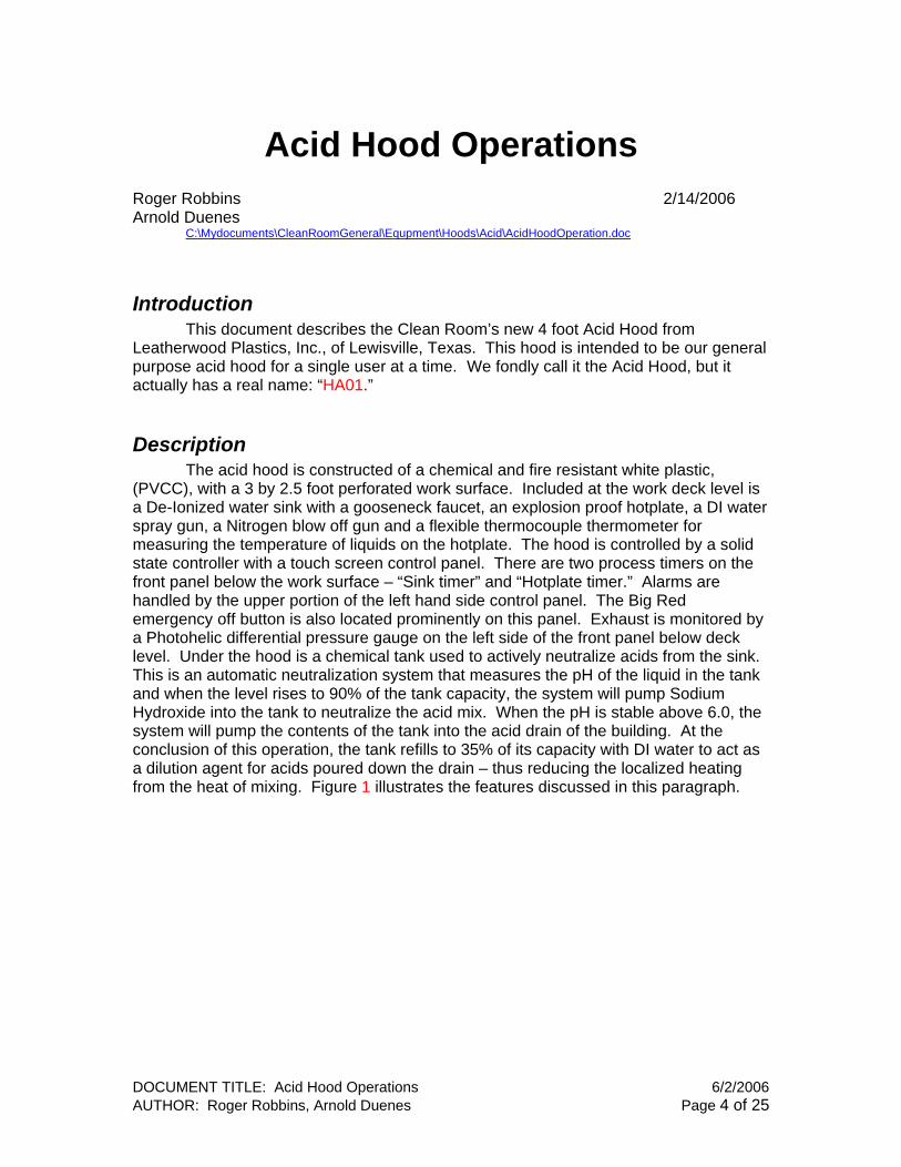
Introduction This document describes the Clean Room’s new 4 foot Acid Hood from Leatherwood Plastics, Inc., of Lewisville, Texas. This hood is intended to be our general purpose acid hood for a single user at a time. We fondly call it the Acid Hood, but it actually has a real name: “HA01.”
Description The acid hood is constructed of a chemical and fire resistant white plastic, (PVCC), with a 3 by 2.5 foot perforated work surface. Included at the work deck level is a De-Ionized water sink with a gooseneck faucet, an explosion proof hotplate, a DI water spray gun, a Nitrogen blow off gun and a flexible thermocouple thermometer for measuring the temperature of liquids on the hotplate. The hood is controlled by a solid state controller with a touch screen control panel. There are two process timers on the front panel below the work surface – “Sink timer” and “Hotplate timer.” Alarms are handled by the upper portion of the left hand side control panel. The Big Red emergency off button is also located prominently on this panel. Exhaust is monitored by a Photohelic differential pressure gauge on the left side of the front panel below deck level. Under the hood is a chemical tank used to actively neutralize acids from the sink. This is an automatic neutralization system that measures the pH of the liquid in the tank and when the level rises to 90% of the tank capacity, the system will pump Sodium Hydroxide into the tank to neutralize the acid mix. When the pH is stable above 6.0, the system will pump the contents of the tank into the acid drain of the building. At the conclusion of this operation, the tank refills to 35% of its capacity with DI water to act as a dilution agent for acids poured down the drain – thus reducing the localized heating from the heat of mixing. Figure 1 illustrates the features discussed in this paragraph.
DOCUMENT TITLE: Acid Hood Operations 6/2/2006 AUTHOR: Roger Robbins, Arnold Duenes Page 4 of 25

Exhaust Alarm
Control Panel
Beaker Thermocouple Thermometer
HF Antidote
Manual Hotplate
Touch Screen
Process Timers Start & Stop Buttons
DI Water Faucet & Acid Sink
DI Water Gun
Exhaust Pressure Gauge
N2 Gun
Figure 1. Illustration of 4 ft Acid Hood features.
Feature Details
Control Panel The control panel is shown in Figure 2 with labels. This panel is composed of two segments: 1) a section of actuator buttons and indicator lights, and 2) a touch screen linked to a microprocessor for controlling the operation of the hood. These will be described in detail in the following sections.
DI Water The hood has a recirculating de-ionized water plumbing system to prevent stagnant water from growing microorganisms and contaminating the purity of the water. There is a monitor readout of this condition at the top of the control panel that displays the resistivity of the water in meg ohms. The nominal value of good DI water is 18.1 meg ohms or better. If you notice that the value has slipped below the 17 meg ohm level, please notify the clean room staff and if this would impact your work, discontinue processing your work in this hood.
DOCUMENT TITLE: Acid Hood Operations 6/2/2006 AUTHOR: Roger Robbins, Arnold Duenes Page 5 of 25
DI Water Condition Meter (Meg Ohms)
Loss of Exhaust Indicator Light
Hood Start Button
Audio Alarm Enunciator
Emergency OFF Button
Alarm Silence Button
Hood Power off Button
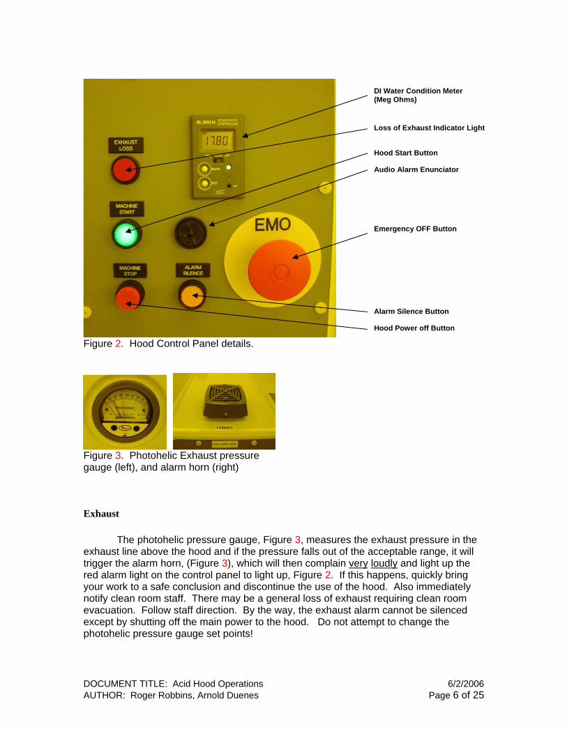
Figure 2. Hood Control Panel details.
Figure 3. Photohelic Exhaust pressure gauge (left), and alarm horn (right)
Exhaust The photohelic pressure gauge, Figure 3, measures the exhaust pressure in the exhaust line above the hood and if the pressure falls out of the acceptable range, it will trigger the alarm horn, (Figure 3), which will then complain very loudly and light up the red alarm light on the control panel to light up, Figure 2. If this happens, quickly bring your work to a safe conclusion and discontinue the use of the hood. Also immediately notify clean room staff. There may be a general loss of exhaust requiring clean room evacuation. Follow staff direction. By the way, the exhaust alarm cannot be silenced except by shutting off the main power to the hood. Do not attempt to change the photohelic pressure gauge set points!
DOCUMENT TITLE: Acid Hood Operations 6/2/2006 AUTHOR: Roger Robbins, Arnold Duenes Page 6 of 25
Machine Start/Stop The Green “HOOD START” button on the control panel turns on the electricity to the hood functions. The Red “MACHINE STOP” button turns off “most” of the electricity to the hood. The hood is generally left “ON” all the time. This control is used when service or problem diagnostic is required.
EMO Button The EMergency Off button is used if the hood is having an electrical problem that portends of immediate emergency. If there is smoke coming from the insides or the hotplate is seriously overheating, etc. Please don’t hesitate to use this button. If you have had to push the EMO button, please notify Clean Room Staff immediately!
Audio Enunciator The audio enunciator is a piezoelectric beeper that announces either a non-emergency fault or the completion of a timed event. There is a convenient yellow alarm silencer button which you can use to cause immediate cessation of the annoying beeps. However, please make sure that the cause of this alarm is corrected before leaving the hood. Notify Clean Room staff if necessary.
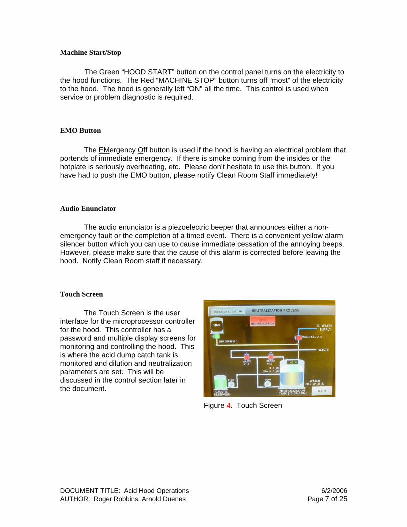
Touch Screen The Touch Screen is the user interface for the microprocessor controller for the hood. This controller has a password and multiple display screens for monitoring and controlling the hood. This is where the acid dump catch tank is monitored and dilution and neutralization parameters are set. This will be discussed in the control section later in the document. Figure 4. Touch Screen
DOCUMENT TITLE: Acid Hood Operations 6/2/2006 AUTHOR: Roger Robbins, Arnold Duenes Page 7 of 25
Process Features
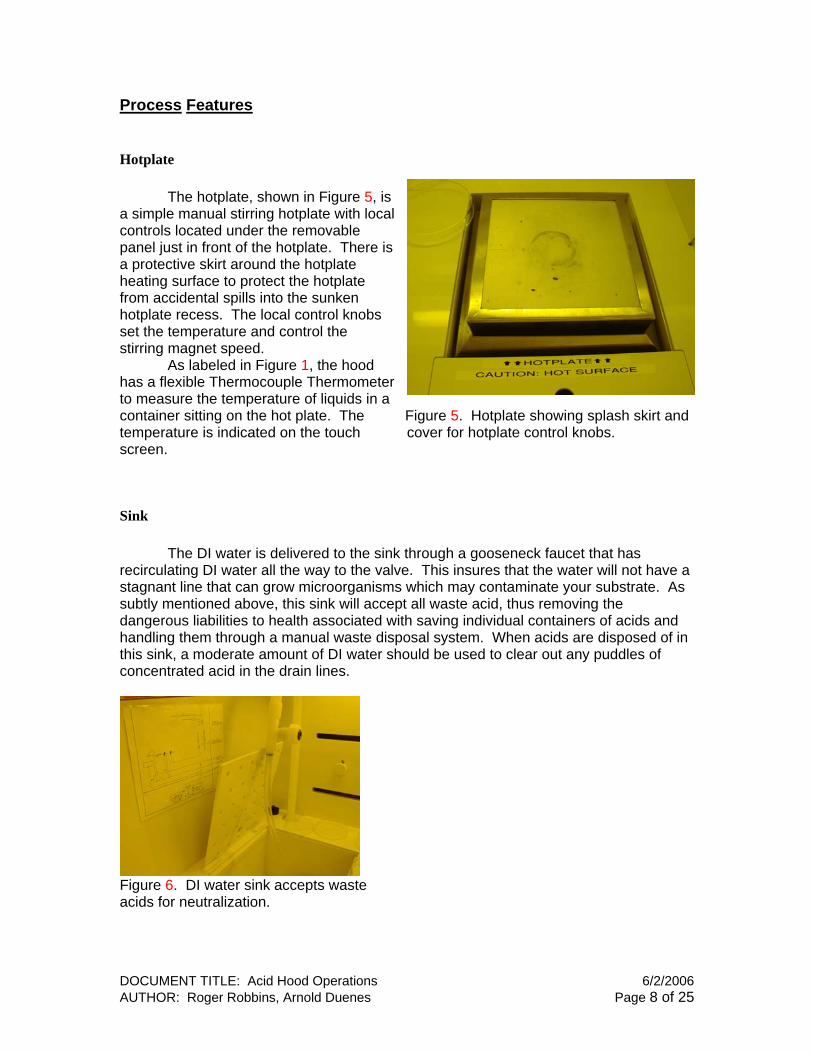
Hotplate The hotplate, shown in Figure 5, is a simple manual stirring hotplate with lcontrols located under the removpanel just in front of the hotplate. Tha protective skirt around the hotplateheating surface to protect the hotplate from accidental spills into the sunken hotplate recess. The local control knobs set the temperature and control the stirring magnet speed.
ocal able
ere is
hermometer
d dicated on the touch cover for hotplate control knobs.
Sink
he DI water is delivered to the sink through a gooseneck faucet that has recircu ave a
ids and
As labeled in Figure 1, the hood has a flexible Thermocouple Tto measure the temperature of liquids in a container sitting on the hot plate. The Figure 5. Hotplate showing splash skirt antemperature is inscreen.
Tlating DI water all the way to the valve. This insures that the water will not h
stagnant line that can grow microorganisms which may contaminate your substrate. As subtly mentioned above, this sink will accept all waste acid, thus removing the dangerous liabilities to health associated with saving individual containers of achandling them through a manual waste disposal system. When acids are disposed of inthis sink, a moderate amount of DI water should be used to clear out any puddles of concentrated acid in the drain lines.
Figure 6. DI water sink accepts wast
e acids for neutralization.
DOCUMENT TITLE: Acid Hood Operations 6/2/2006 AUTHOR: Roger Robbins, Arnold Duenes Page 8 of 25

Acid Neutralization Tank
When fluids drain out of the sink,
tive
in
nto the
a
that make a noticeable clacking sound from
N2 Gun and DI Water Spray
The hood has the standard Nitrogen blow-off gun and DI water spray hose to f
igure 1
HF Acid Antidote
There should always be a supply of Hydrofluoric Acid (HF) antidote in plastic
ct o
they drain directly into a catch tank under the hood. This tank has an acneutralization system that measures the pH and supplies a 50% concentrated Sodium Hydroxide solution to the tanka programmed cycle to neutralize the acid. When the tank is full, the neutralized solution is pumped ibuilding acid drain. There are two pumps involved with this system: 1)recirculating pump used to stir the fluidin the tank, and 2) a caustic pump to Reservoir (Left) under the hood.
Figure 7. Catch tank (Right) and Caustic
deliver the Sodium Hydroxide. Both of these pumps are diaphragm pumpsbehind the hood – this is normal.
facilitate drying and water rinsing of substrates. Note that the DI water hose is made ocoaxial Teflon tubing and is somewhat stiff to stretch, and it will spring back with considerable force if it slips out of your hands – be careful and get a good grip. Fshows the recessed location of both these hood tools.
tubes in the back of the hood work surface. If you accidentally get HF on your skin, wash it off with DI water for about 10 minutes and then apply the antidote crème by rubbing it into the skin for about 5 minutes. This Calcium Gluconate antidote will reawith the HF to create benign Calcium Fluoride salt, thus capturing the F- ions that can dserious damage to the body. If a large spill gets on you then remove clothing and do a 15 minute shower in the emergency shower at the entrance to the room. Call for help immediately – contact with this much HF could be life threatening. If you get a lot of HFacid on your body, your buddy must call 911 to get paramedic help and be checked out by a doctor quickly. More information on this situation is contained in the Clean Room Safety Handbook.
(Tube of Calcium Gluconate Gel – HF Antidote)
DOCUMENT TITLE: Acid Hood Operations 6/2/2006 AUTHOR: Roger Robbins, Arnold Duenes Page 9 of 25
Operating Software
Overview tions are controlled by a microprocessor whose interface mentioned touch screen on the control panel. The control
rocessor is concerned with two significant hood functions: 1) Neutralization of the the work surface, and 2) general
r/temperature/alarm data presentation. These functions will be discussed in
will be a soft button at the very top enter of the screen entitled “Log-in,” as shown in
7. The login level enables various portions ontroller capability to the operator. Normally
level.
option buttons
parameter changes reserved for staff. If e staff person in charge of the hood. Push
have to login. (Figure 8 shows a
The active hood funcwith the operator is the afore The active hood funcwith the operator is the aforeppcollected acid in the catch tank undersecurity/timecollected acid in the catch tank undersecurity/timedetail below.
Login From the “Main” screen on the touch screen, there
detail below.
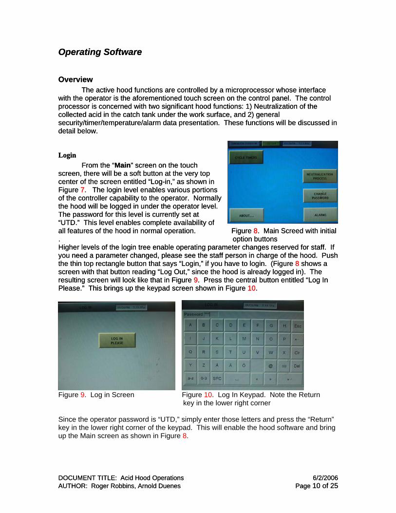
Login From the “Main” screen on the touch screen, there ccFigure of the cFigure of the cthe hood will be logged in under the operator The password for this level is currently set at “UTD.” This level enables complete availability of all features of the hood in normal operation. . Higher levels of the login tree enable operatingyou need a parameter changed, please see ththe thin top rectangle button that says “Login,” if you screen with that button reading “Log Out,” since the hood is already logged in). The resulting screen will look like that in Figure 9. Press the central button entitled “Log In Please.” This brings up the keypad screen shown in Figure 10.
the hood will be logged in under the operator The password for this level is currently set at “UTD.” This level enables complete availability of all features of the hood in normal operation. . Higher levels of the login tree enable operatingyou need a parameter changed, please see ththe thin top rectangle button that says “Login,” if you screen with that button reading “Log Out,” since the hood is already logged in). The resulting screen will look like that in Figure 9. Press the central button entitled “Log In Please.” This brings up the keypad screen shown in Figure 10.
Figure 8. Main Screed with initial
DOCUMENT TITLE: Acid Hood Operations 6/2/2006 AUTHOR: Roger Robbins, Arnold Duenes Page 10 of 25
Operating Software
Overview tions are controlled by a microprocessor whose interface mentioned touch screen on the control panel. The control
rocessor is concerned with two significant hood functions: 1) Neutralization of the the work surface, and 2) general
r/temperature/alarm data presentation. These functions will be discussed in
will be a soft button at the very top enter of the screen entitled “Log-in,” as shown in
7. The login level enables various portions ontroller capability to the operator. Normally
level.
Figure 8. Main Screed with initial option buttons
parameter changes reserved for staff. If e staff person in charge of the hood. Push
have to login. (Figure 8 shows a
Figure 9. Log in Screen Figure 10. Log In Keypad. Note the Return key in the lower right corner Since the operator password is “UTD,” simply enter those letters and press the “Return” key in the lower right corner of the keypad. This will enable the hood software and bring up the Main screen as shown in Figu . re 8
DOCUMENT TITLE: Acid Hood Operations 6/2/2006 AUTHOR: Roger Robbins, Arnold Duenes Page 10 of 25

Timer Operation The two buttons on the Main screen important to hood operators are the ones
ntitled “Cycle Timers,” and “Neutralization Process.” Pressing the “Cycle Timers” utton produces a new screen as in Figure 11, and shows the timer indicators.
eb
Figure 11. Cycle Timer screen. Enter time by pressing the appropriate numeral block until the desired number appears. The clocks are started from the front panel on the front surface under the work area.
and the system will return to the Main screen ed and stopped from the front panel below the
en also shows the liquid-in-beaker re.
andard operations is the “Neutralization” creen. This is a somewhat complicated depiction of the hood’s drain plumbing and eutralization pumping and valving system. Figure 12 shows this screen.
When you have the time set, press “Main” for additional action. The timers are startwork surface as indicated in Figure 1. This screthermocouple thermometer temperatu
Neutralization System The screen view most useful for stsn
DOCUMENT TITLE: Acid Hood Operations 6/2/2006 AUTHOR: Roger Robbins, Arnold Duenes Page 11 of 25
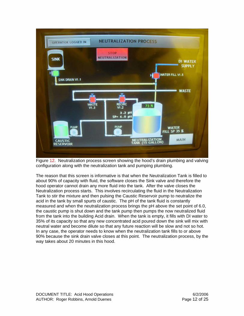
Figure 12. Neutralization process screen showing the hood’s drain plumbing and valving configuration along with the neutralization tank and pumping plumbing. The reason that this screen is informative is that when the Neutralization Tank is filled to about 90% of capacity with fluid, the software closes the Sink valve and therefore the hood operator cannot drain any more fluid into the tank. After the valve closes the Neutralization process starts. This involves recirculating the fluid in the Neutralization Tank to stir the mixture and then pulsing the Caustic Reservoir pump to neutralize the acid in the tank by small spurts of caustic. The pH of the tank fluid is constantly measured and when the neutralization process brings the pH above the set point of 6.0, the caustic pump is shut down and the tank pump then pumps the now neutralized fluid from the tank into the building Acid drain. When the tank is empty, it fills with DI water to 35% of its capacity so that any new concentrated acid poured down the sink will mix with neutral water and become dilute so that any future reaction will be slow and not so hot. In any case, the operator needs to know when the neutralization tank fills to or above 90% because the sink drain valve closes at this point. The neutralization process, by the way takes about 20 minutes in this hood.
DOCUMENT TITLE: Acid Hood Operations 6/2/2006 AUTHOR: Roger Robbins, Arnold Duenes Page 12 of 25

Neutralization Chemistry This section will be a short exposition of simple neutralization chemistry. The purpose is to understand how the acids are neutralized and how much Sodium Hydroxide (NaOH) is required to neutralize a given quantity of acid. This is somewhat complicated because in this general purpose hood, we will be neutralizing a number of different acids with different initial concentrations. The amount of base, (NaOH is our choice) required to neutralize the acid depends on what type of acid and how concentrated it is compared to the base concentration. The concept of neutralization states that the base has to supply OH- ions to the solution in such numbers as to match the number of H+ ions that the acid has added to the solution. This means that we need to know what the reaction equation looks like and what the oxidation number is for the reactants. In fact we need to recall a number of chemical definitions to be able to calculate the volumes of the constituents involved in the neutralization.
Chemical Definitions
Mole One Mole of a substance is its collective molecular weight expressed in grams, (formula weight). EX: H2SO4 = 2x1 +1x32 + 4x16 98gm (Red numbers are atomic masses and multipliers are the number of times the atom appears in the molecule)
Gram-Equivalent Weight One gram-equivalent weight, (E), of a substance is its gram-atomic weight divided by its oxidation number. EX: H2SO4 = (2x1 + 1x32 + 4x16)/2 E = 49gm-eq (Red numbers are atomic masses, multipliers are the number of times the atom appears in the molecule, and the Blue 2 is the oxidation number of the sulfate ion (SO4
-2) in the sulfuric acid molecule reacting with NaOH)
DOCUMENT TITLE: Acid Hood Operations 6/2/2006 AUTHOR: Roger Robbins, Arnold Duenes Page 13 of 25
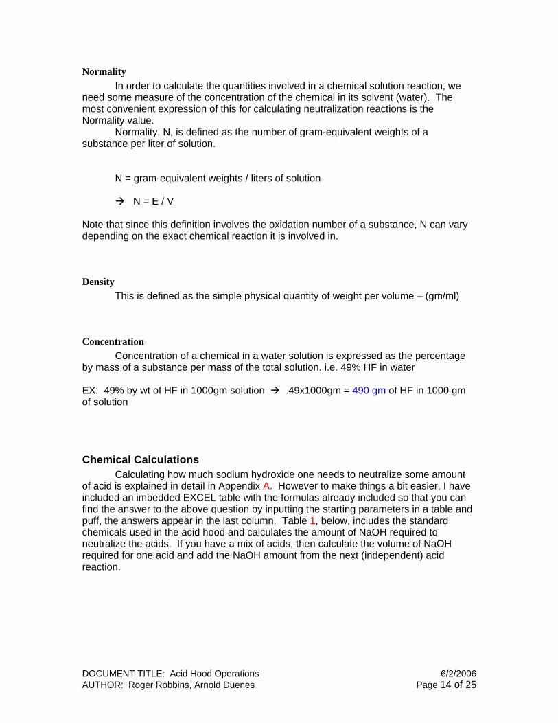
Normality In order to calculate the quantities involved in a chemical solution reaction, we need some measure of the concentration of the chemical in its solvent (water). The most convenient expression of this for calculating neutralization reactions is the Normality value. Normality, N, is defined as the number of gram-equivalent weights of a substance per liter of solution. N = gram-equivalent weights / liters of solution N = E / V Note that since this definition involves the oxidation number of a substance, N can vary depending on the exact chemical reaction it is involved in.
Density This is defined as the simple physical quantity of weight per volume – (gm/ml)
Concentration Concentration of a chemical in a water solution is expressed as the percentage by mass of a substance per mass of the total solution. i.e. 49% HF in water EX: 49% by wt of HF in 1000gm solution .49x1000gm = 490 gm of HF in 1000 gm of solution
Chemical Calculations Calculating how much sodium hydroxide one needs to neutralize some amount of acid is explained in detail in Appendix A. However to make things a bit easier, I have included an imbedded EXCEL table with the formulas already included so that you can find the answer to the above question by inputting the starting parameters in a table and puff, the answers appear in the last column. Table 1, below, includes the standard chemicals used in the acid hood and calculates the amount of NaOH required to neutralize the acids. If you have a mix of acids, then calculate the volume of NaOH required for one acid and add the NaOH amount from the next (independent) acid reaction.
DOCUMENT TITLE: Acid Hood Operations 6/2/2006 AUTHOR: Roger Robbins, Arnold Duenes Page 14 of 25
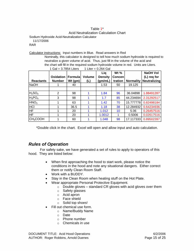
Table 1*
Acid Neutralization Calculation Chart Sodium Hydroxide Acid-Neutralization Calculator
11/17/2006RAR
Calculator instructions: Input numbers in Blue. Read answers in Red Nominally, this calculator is designed to tell how much sodium hydroxide is required to neutralize a given volume of acid. Thus, just fill in the volume of the acid and the chart will fill in the required sodium hydroxide volume in red. Units are Liters.
1 Gal = 3.7854 Liters 1 Liter = 0.264 Gal
ReactantsOxidation Number
Formula Wt (gm)
Volume (L)
Liq Density (gm/mL)
Wt % Concentration Normality
NaOH Vol (L) req for
NeutralizingNaOH 1 40 1.53 50 19.125
H2SO4 2 98 1 1.84 96 36.04898 1.884913972.312925170.824981840.642349360.264575160.026175160.89502397
H3PO4 3 98 1 1.7 85 44.234694HNO3 1 63 1 1.42 70 15.777778HCl 1 36.5 1 1.18 38 12.284932HF 1 20 1 1.012 10 5.06HF 1 20 1 1.0012 1 0.5006CH3COOH 1 60 1 1.048 98 17.117333
*Double click in the chart. Excel will open and allow input and auto calculation.
Rules of Operation For safety sake, we have generated a set of rules to apply to operators of this
hood. They are listed below:
• When first approaching the hood to start work, please notice the conditions in the hood and note any situational dangers. Either correct them or notify Clean Room Staff.
• Work with a BUDDY. • Stay in the Clean Room when heating stuff on the Hot Plate. • Wear appropriate Personal Protective Equipment.
o Double gloves – standard CR gloves with acid gloves over them o Safety glasses o Acid apron o Face shield o Solid top shoes!
• Fill out chemical use form. o Name/Buddy Name o Date o Phone number o Chemicals in use
DOCUMENT TITLE: Acid Hood Operations 6/2/2006 AUTHOR: Roger Robbins, Arnold Duenes Page 15 of 25
• Only one experiment at a time is allowed. • Never place a chemical container on the floor. • Acid Hood glassware is stored on the cart to the left of the hood. • Always remember to turn off the hotplate when you are finished. • Dispose of your acids in the sink while running a moderate amount of DI
water with the acid. o Rinse your acid containers thoroughly with DI water o Wet wipe and dry off the work surface so the following person will
not be harmed by liquid acid spills. • When you are finished, clean up your work area and return all the tools
and PPE you have been using to their proper place – especially papers and rags.
DOCUMENT TITLE: Acid Hood Operations 6/2/2006 AUTHOR: Roger Robbins, Arnold Duenes Page 16 of 25
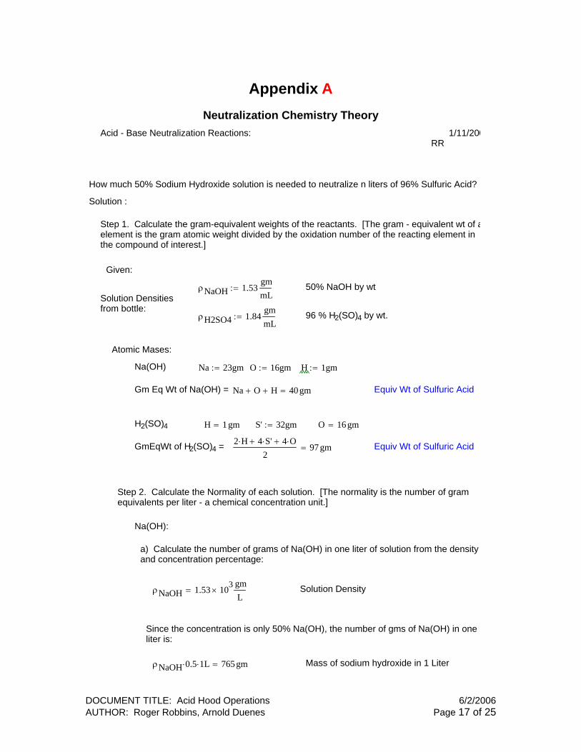
Appendix A Neutralization Chemistry Theory
Acid - Base Neutralization Reactions: 1/11/200 RR
How much 50% Sodium Hydroxide solution is needed to neutralize n liters of 96% Sulfuric Acid?
Solution :
Step 1. Calculate the gram-equivalent weights of the reactants. [The gram - equivalent wt of aelement is the gram atomic weight divided by the oxidation number of the reacting element inthe compound of interest.]
Given:
ρNaOH 1.53gmmL
:= 50% NaOH by wtSolution Densitiesfrom bottle:
ρH2SO4 1.84gmmL
:= 96 % H2(SO)4 by wt.
Atomic Mases:
Na(OH) Na 23gm:= O 16gm:= H 1gm:=
Gm Eq Wt of Na(OH) = Na O+ H+ 40gm= Equiv Wt of Sulfuric Acid
H2(SO)4 H 1gm= S' 32gm:= O 16 gm=
GmEqWt of H2(SO)4 = 2 H⋅ 4 S'⋅+ 4 O⋅+2
97gm= Equiv Wt of Sulfuric Acid
Step 2. Calculate the Normality of each solution. [The normality is the number of gramequivalents per liter - a chemical concentration unit.]
Na(OH):
a) Calculate the number of grams of Na(OH) in one liter of solution from the densityand concentration percentage:
ρNaOH 1.53 103×
gmL
= Solution Density
Since the concentration is only 50% Na(OH), the number of gms of Na(OH) in oneliter is:
ρNaOH 0.5⋅ 1⋅ L 765gm= Mass of sodium hydroxide in 1 Liter
DOCUMENT TITLE: Acid Hood Operations 6/2/2006 AUTHOR: Roger Robbins, Arnold Duenes Page 17 of 25
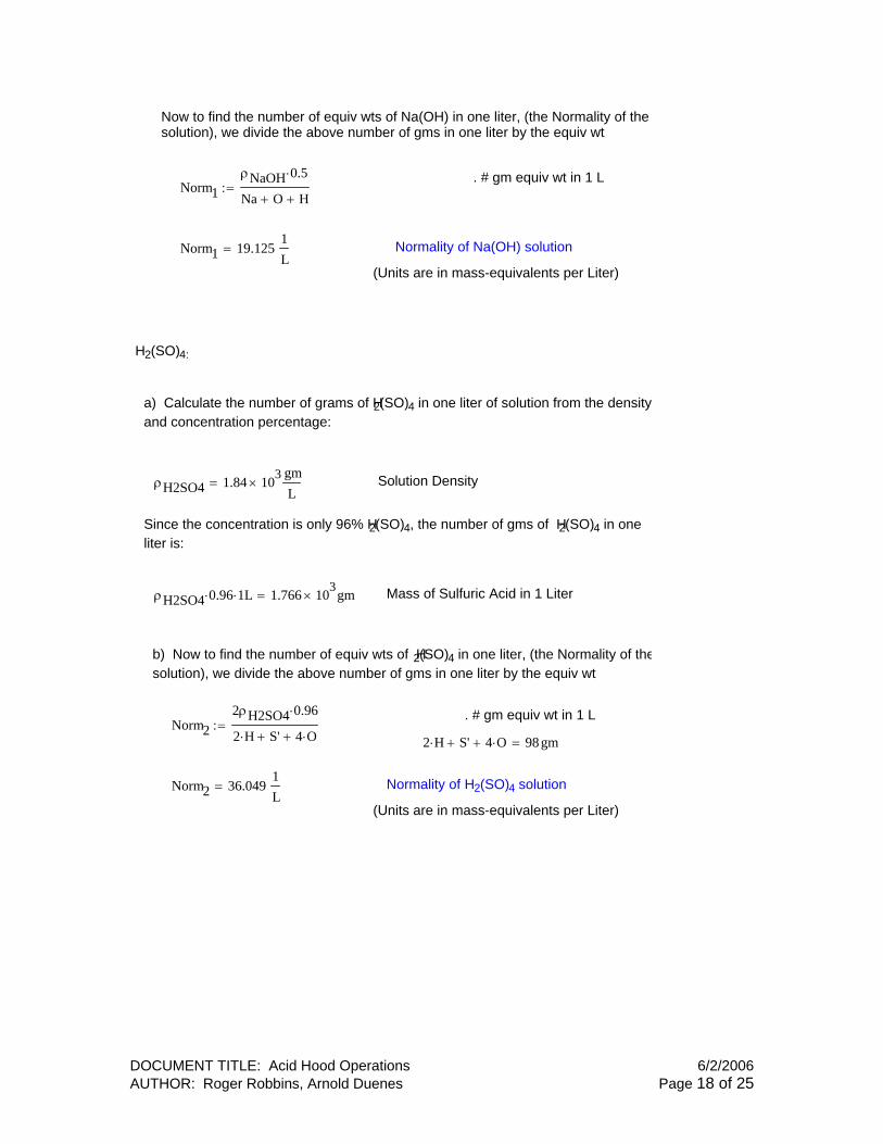
Now to find the number of equiv wts of Na(OH) in one liter, (the Normality of thesolution), we divide the above number of gms in one liter by the equiv wt
. # gm equiv wt in 1 LNorm1
ρNaOH 0.5⋅
Na O+ H+:=
Norm1 19.1251L
= Normality of Na(OH) solution
(Units are in mass-equivalents per Liter)
H2(SO)4:
a) Calculate the number of grams of H2(SO)4 in one liter of solution from the densityand concentration percentage:
ρH2SO4 1.84 103×
gmL
= Solution Density
Since the concentration is only 96% H2(SO)4, the number of gms of H2(SO)4 in oneliter is:
ρH2SO4 0.96⋅ 1⋅ L 1.766 103× gm= Mass of Sulfuric Acid in 1 Liter
b) Now to find the number of equiv wts of H2(SO)4 in one liter, (the Normality of thesolution), we divide the above number of gms in one liter by the equiv wt
. # gm equiv wt in 1 LNorm2
2ρH2SO4 0.96⋅
2 H⋅ S'+ 4 O⋅+:=
2 H⋅ S'+ 4 O⋅+ 98gm=
Norm2 36.0491L
= Normality of H2(SO)4 solution
(Units are in mass-equivalents per Liter)
DOCUMENT TITLE: Acid Hood Operations 6/2/2006 AUTHOR: Roger Robbins, Arnold Duenes Page 18 of 25

Step 3 Calculate the amount of Na(OH) required to neutralize a given amount of Sulfuric acidThe law of neutralization claims that the number of gm equivalent weights of base neutralize tsame number of gram equivalents of acid.
Stated in different form, the Neutralization rule claims:
. H2(SO)4 + 2Na(OH) ---> Na2(SO)4 + 2H2O
Norm2 V2⋅ Norm1 V1⋅ (Claim)
(Norm2 is the Normality of the acid)
Therefore, to calculate the volume of sodium hydroxide required to neutralize, say 4liters of sulfuric acid:
V2 4L:=
V1Norm2Norm1
V2⋅:= (Claim equation rearranged)
V1 7.54 L= ANSWER: The volume of sodium hydroxiderequired to neutralize 4 Liters of sulfuric acid is7.54 Liters, takng into account the solutionconcentrations specified.
DOCUMENT TITLE: Acid Hood Operations 6/2/2006 AUTHOR: Roger Robbins, Arnold Duenes Page 19 of 25

Appendix B Neutralization: Staff Procedure
Arnold Duenes
Purpose This appendix is intended to explain to Clean Room Staff how to run a neutralization operation on Leatherwood Plastic’s General 4 ft Acid Bench #189.
NOTES: • Execution of this procedure is limited to trained Clean Room Staff Only • Proper Personal Protective Equipment is requires when operating bench or
during maintenance. • The name of this hood is “HA01.” …means Hood, Acid, #1 • The Neutralization Process must be ENABLED on the touch screen.
Neutralization Introduction This acid hood (HA01), has an onboard acid neutralization system located under the work deck. Acid waste dumped in the DI Water/Acid sink will drain into a 15 gallon neutralization tank, and when the tank level reaches 90% full (13.5 gal), the pneumatic valve below the sink will close. If the neutralization process is ENABLED, and the liquid in the neutralization tank has a pH lower than 6.0, a 50% solution of NaOH (Sodium Hydroxide) will be pumped into the tank from a smaller 2 gallon caustic reservoir until the pH is equal to or greater than 6.0. At this point, the liquid in the neutralization tank will be recirculated (stirred) for a programmed specific time period and then pumped to the building acid drain. When the tank level drops to 5% or less, the drain cycle will cease and new DI water will fill the tank to 35% (5.25 gal), recirculate for 3 minutes and then the DI Water/Acid sink valve will open. At this point the hood can be used again.
Neutralization Procedure 1. Once logged in, [from the main menu], you can access the neutralization menu
by selecting NEUTRALIZATION PROCESS, (Figure B1).
Login:
Figure B1. Sequence of screens to enable login. Select Neutralization: Resulting the screen:
DOCUMENT TITLE: Acid Hood Operations 6/2/2006 AUTHOR: Roger Robbins, Arnold Duenes Page 20 of 25
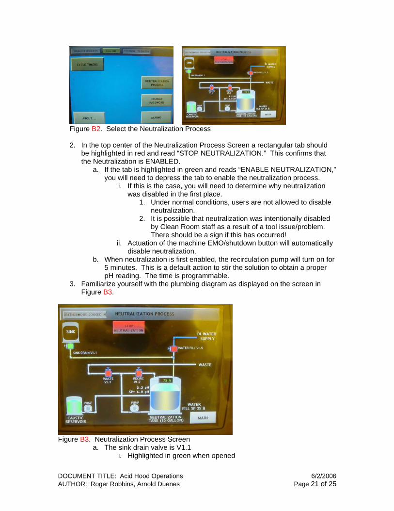
Figure B2. Select the Neutralization Process 2. In the top center of the Neutralization Process Screen a rectangular tab should
be highlighted in red and read “STOP NEUTRALIZATION.” This confirms that the Neutralization is ENABLED.
a. If the tab is highlighted in green and reads “ENABLE NEUTRALIZATION,” you will need to depress the tab to enable the neutralization process.
i. If this is the case, you will need to determine why neutralization was disabled in the first place.
1. Under normal conditions, users are not allowed to disable neutralization.
2. It is possible that neutralization was intentionally disabled by Clean Room staff as a result of a tool issue/problem. There should be a sign if this has occurred!
ii. Actuation of the machine EMO/shutdown button will automatically disable neutralization.
b. When neutralization is first enabled, the recirculation pump will turn on for 5 minutes. This is a default action to stir the solution to obtain a proper pH reading. The time is programmable.
3. Familiarize yourself with the plumbing diagram as displayed on the screen in Figure B3.
Figure B3. Neutralization Process Screen
a. The sink drain valve is V1.1 i. Highlighted in green when opened
DOCUMENT TITLE: Acid Hood Operations 6/2/2006 AUTHOR: Roger Robbins, Arnold Duenes Page 21 of 25

ii. Highlighted in red when closed b. Actual and set-point pH are displayed next to the neutralization tank
symbol i. The top pH reading is the actual pH ii. SP (Set Point) pH reading should be 6.0 (a programmable
parameter) c. There are 3 other pneumatic operated valves in the diagram:
i. V1.2 = recirculation valve (stirs contents of tank) ii. V1.3 = waste drain valve (valve opens when pumping to drain) iii. V1.5 = DI Water fill valve
d. There are two pumps in the diagram: i. Recirculation pump (next to neutralization tank) ii. Caustic Supply pump (next to caustic reservoir)
e. The Neutralization tank icon displays a real-time liquid level i. Note these tank level parameters:
1. The sink valve closes when a 90% tank level is reached 2. At 5% or less, the hood will switch from drain to DI Water
fill. 3. DI Water will fill tank to 35% full (programmable parameter)
f. The caustic reservoir icon will always show green (full) unless it is empty i. There is only one float sensor at the bottom of the caustic
reservoir ii. Wear appropriate PPE when refilling the 2 gal caustic reservoir
with 50% concentrated NaOH. (Splash back is common because of the viscosity of the solution)
1. Wear acid gloves, apron and face shield 4. During normal operation, users are trained to be aware of the tank level,
especially when it is very close to 90%. In such a case, it is best to flow DI Water from the gooseneck faucet, reach 90% full, then wait for neutralization to complete (normally it takes about 20 minutes for the tank contents to be neutralized and pumped to acid drain). This practice is intended to prevent noxious levels of acid waste to collect in the sink while neutralization is taking place.
a. Summary i. If tank level is 87% - 90% full, flow DI Water into the sink from
sprayer or gooseneck to achieve 90% full and start of Neutralization process. Wait for process to complete ~ 20 min
ii. At 90% full, the sink valve will close and neutralization will take place if needed; if contents are already neutralized, they will be pumped to drain when the 3 min stabilization time expires.
iii. Inform potential users that the hood is unavailable when the sink valves close – they will know not to use hood
iv. Visually check the level of caustic in the under deck reservoir (Add NaOH if necessary) Figure B4.
DOCUMENT TITLE: Acid Hood Operations 6/2/2006 AUTHOR: Roger Robbins, Arnold Duenes Page 22 of 25

Figure B4. Under Deck caustic tank (left) and neutralization tank (Right). The caustic tank will slide out enough to fill through the lift-off lid at the front top.
Neutralization Parameters
1. Normally, the hood is set to level 1 access: OPERATOR LOGGED IN 2. To access the menus where all programmable parameters are found, you must
log in to level 5 access: LEATHERWOOD LOGGED IN a. To accomplish this, you must first log out b. Log in using the tool’s manufacturer serial number
i. For security this number is intentionally not included in this document.
ii. Your training will include this number. If only you could remember it…
3. Looking at the main Menu, the tab menus labeled Process Monitor/Setup and Tool Setup Parameters are where all neutralization parameter are found.
Figure B5. Highest level Login Screen: LEATHERWOOD LOGGED IN
DOCUMENT TITLE: Acid Hood Operations 6/2/2006 AUTHOR: Roger Robbins, Arnold Duenes Page 23 of 25
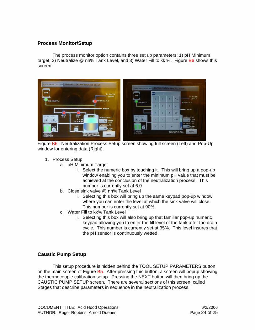
Process Monitor/Setup The process monitor option contains three set up parameters: 1) pH Minimum target, 2) Neutralize @ nn% Tank Level, and 3) Water Fill to kk %. Figure B6 shows this screen.
Figure B6. Neutralization Process Setup screen showing full screen (Left) and Pop-Up window for entering data (Right).
1. Process Setup a. pH Minimum Target
i. Select the numeric box by touching it. This will bring up a pop-up window enabling you to enter the minimum pH value that must be achieved at the conclusion of the neutralization process. This number is currently set at 6.0
b. Close sink valve @ nn% Tank Level i. Selecting this box will bring up the same keypad pop-up window
where you can enter the level at which the sink valve will close. This number is currently set at 90%
c. Water Fill to kk% Tank Level i. Selecting this box will also bring up that familiar pop-up numeric
keypad allowing you to enter the fill level of the tank after the drain cycle. This number is currently set at 35%. This level insures that the pH sensor is continuously wetted.
Caustic Pump Setup This setup procedure is hidden behind the TOOL SETUP PARAMETERS button on the main screen of Figure B5. After pressing this button, a screen will popup showing the thermocouple calibration setup. Pressing the NEXT button will then bring up the CAUSTIC PUMP SETUP screen. There are several sections of this screen, called Stages that describe parameters in sequence in the neutralization process.
DOCUMENT TITLE: Acid Hood Operations 6/2/2006 AUTHOR: Roger Robbins, Arnold Duenes Page 24 of 25

Figure B7. Caustic Pump Setup Screen displays by touching the NEXT button from the Left screen that popped up when you hit the TOOL SETUP PARAMETERS button on the MAIN screen (Figure B5).
1. Stage 1 a. Caustic Pump RUN Constantly Below n.n pH. This means that the
caustic pump will supply Sodium Hydroxide continuously if the actual pH of the tank contents is less than n.n. Currently this number is set at 1.0.
2. Stage 2. a. The button labeled “pH Stabilize Time After Reaching Stage 1 Prior to pH
Set-point” allows a time input that sets the amount of time that the system will wait after reaching a pH of n.n (1.0) before it moves on to stage 3. If, in this wait time the pH falls below n.n (1.0), it will again pump Sodium Hydroxide continuously until n.n (1.0) or higher is achieved.
b. “Caustic Pump Cycle after Reaching Stage 1 Set-point” is currently set at 2 sec ON, and 15 sec OFF. After the 2 min stabilization time expires, the caustic pump will use these ON/OFF times to cycle (pump Sodium Hydroxide) until the desired pH value is achieved, i.e. a pH of 6.0.
3. Stage 3 a. “pH Stabilize Time After Reaching pH Set-point Prior To Waste Dump” is
currently set at 3 min 0 sec. This means that once a pH of 6.0 or above is achieved, the system will wait for this amount of time and then pump to drain the tank.
b. Other parameters in this menu i. Recirculation Pump – the caustic pump uses these parameters
when neutralization is enabled. The current parameters are 5 min ON, 25 min OFF.
ii. pH values (actual and set-point) are displayed in this menu.
DOCUMENT TITLE: Acid Hood Operations 6/2/2006 AUTHOR: Roger Robbins, Arnold Duenes Page 25 of 25