achieving ufs host throughput for system performance
TRANSCRIPT
Achieving UFS Host Throughput For System Performance
Yifei-LiuCAE Manager, Synopsys
Copyright © 2013 SynopsysMobile Forum 2013

Agenda
• UFS Throughput Considerations to Meet Performance Objectives
• UFS Host Controller IP Required Features for Implementation Success
• Meeting UFS Throughput Requirements with UFS Host Controller IP Designed to Maximize UFS Performance
• UFS Host Solution to Future Proof Your Design

UFS Throughput Considerations to Meet Performance Objectives

UFS Subsystem & Its Components
• UFS standard defines the throughput
• Achieving these throughput goals can be challenging
• Requires best practices to maximize throughput
StorageSoC
UniP
roUni
Pro
M-PHY
Tx
Rx UFS Host
ContrlM-PHY
Rx
Tx
UF
S
Dev
ice
Point to point topology
Core
Systembus

UFS 1.1/2.0 Host ControllerThroughput Requirements
UFS 1.1 UFS 2.0
Requirement Gear2 L1 Rate B2915.2Mbps ~=3Gbps ~=365MBps
Gear3 L1 Rate B5836.8 Mbps ~=6Gbps ~=730MBps
20% 8b10bEncoding Overhead
~= 292MBps ~= 584MBps
~ 6% Of UniProOverhead
~= 275MBps ~= 550MBps
Target 300MBps (Unidirectional) 600MBps (Bidirectional)
600MBps (Unidirectional) 1200MBps (Bidirectional)
Total Available Bandwidth at System Bus• Depends on bandwidth allocation on the SOC• Typically can vary from 5% to 30%
System Bandwidth Requirement • UFS 1.1: 800 – 1600MBps• UFS 2.0: 800 – 2400MBps
UFS 1.1/2.0 Host ControllerE2E Throughput Requirements
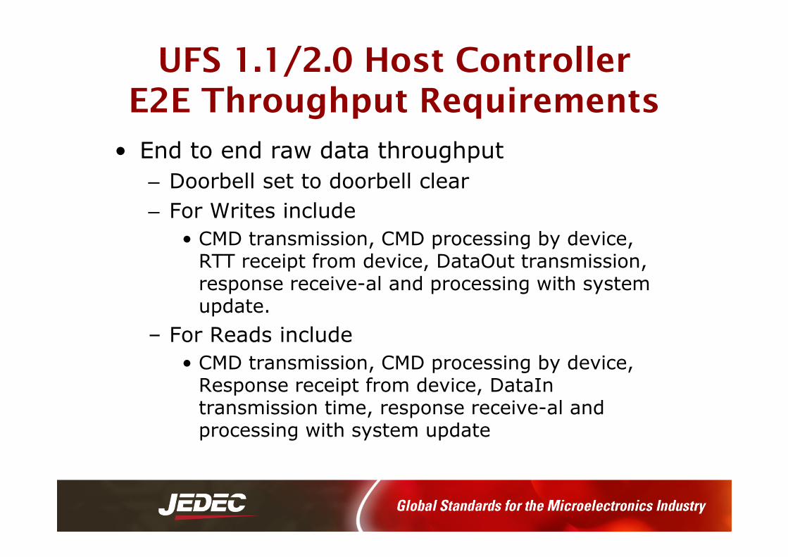
• End to end raw data throughput
– Doorbell set to doorbell clear
– For Writes include
• CMD transmission, CMD processing by device, RTT receipt from device, DataOut transmission, response receive-al and processing with system update.
– For Reads include
• CMD transmission, CMD processing by device, Response receipt from device, DataIntransmission time, response receive-al and processing with system update

UFS 1.1/2.0 Host ControllerE2E Throughput Requirements
• End to end raw data throughput
– Excluding UPIU overhead
– Excluding device Flash read and write times
– Including UniPro and M-PHY latencies
– For single command writes
• 90MBps onwards (assumed conditions of UFS setup)
– For single command reads
• 90MBps onwards(assumed conditions of UFS setup)

UFS Host Controller Throughput Considerations
• System bus side
– System clock frequency
– System fabric configuration• Bus width, burst, size, etc.
• DMA
• Buffer/FIFO size
• Outstanding request number
– System memory bandwidth, efficiency and access latency
• UFS subsystem side
– UniPro setup• C-Port width, FIFO sizes, Group ack, Timeouts, etc.
– Device Response• Type of LUN, number and size of RTTs, attributes, capabilities
– Device/flash read and write times
– Transaction/transfer setup • Read/write sequences, read only, write only, sizes, etc.
• Application software or device drivers
SoC
Unipro
M-PHY
Tx
Rx UFS Host
Contlr
Core
SystemBus
SW
UFS Subsystem and IP Design Considerations
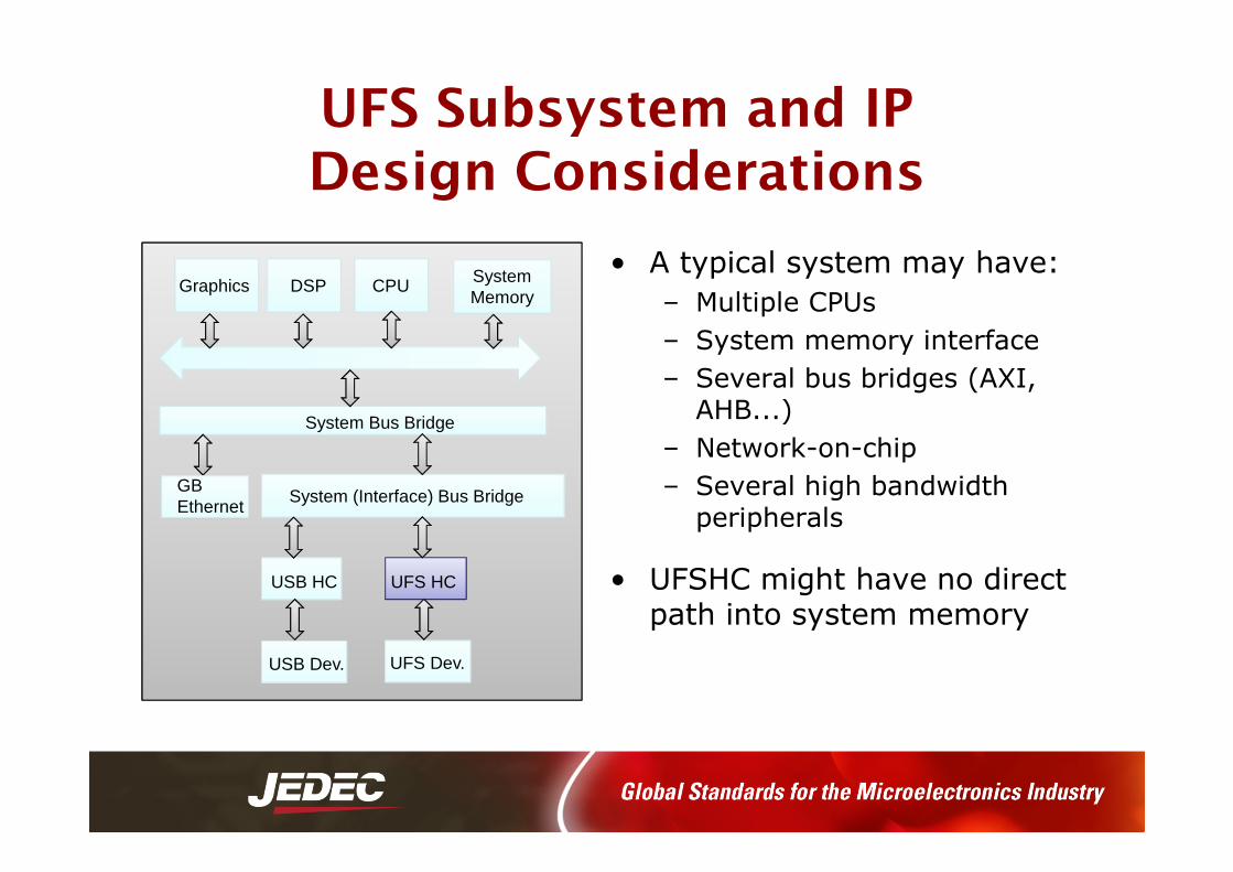
• A typical system may have:
– Multiple CPUs
– System memory interface
– Several bus bridges (AXI, AHB...)
– Network-on-chip
– Several high bandwidth peripherals
• UFSHC might have no direct path into system memory
CPU System Memory
System Bus Bridge
System (Interface) Bus Bridge
UFS HC
UFS Dev.
USB HC
USB Dev.
DSPGraphics
GB Ethernet

UFS Host Controller IP Required Features for Implementation Success

UFS Host Controller Features for Implementation Success
• Scatter/gather DMA to transfer large data blocks
• Burst transfers to maximize DMA throughput and keep system impact minimal
• Pre-configured for up to 32 task requests
• Pre-configured for up to 8 task management requests
• Ability to perform commands without system host intervention
• Support for the full range of UPIU packets, from 32byte to 64kB
• UniPro and M-PHY compliant stack
• DFT and clock gating ready design

UFS Host Controller Hardware & Software Features for Implementation Success
• Software Features (UFS Host Driver)– UPIUs setup & processing
• NOP, CMD, TM, Query, Response, Reject & DataIn
– UTP TM / TR (descriptors) and Data Buffers formation
– UFS Interconnect (Link & PHY) Control
• Hardware Features (UFS Host Controller)– UPIUs processing
• DATAOUT, DATAIN & RTT
– Task and command management
– Data transfer through DMA
– Host Controller register interface (MMIO)
– Interrupt generation
– Vendor-specific features

AXI Features Can Assist in Meeting Throughput
• 32/64-bit address bus and 64 bit-data bus
• Support for INCR bursts reads and writes
• Burst length is a power of 2 (1, 2,…,16, 32) and aligned to that boundary
• Configurable buffer sizes
• Supports configuration read and write outstanding transactions
• Byte enables supported
• Make use of posted writes during data access and non-posted write for certain descriptor access to maximize the AXI bus efficiency

Meeting Throughput Requirements with UFS Host Controller IP Designed to Maximize UFS Performance
System Latency Requirementsto Maximize System Performance
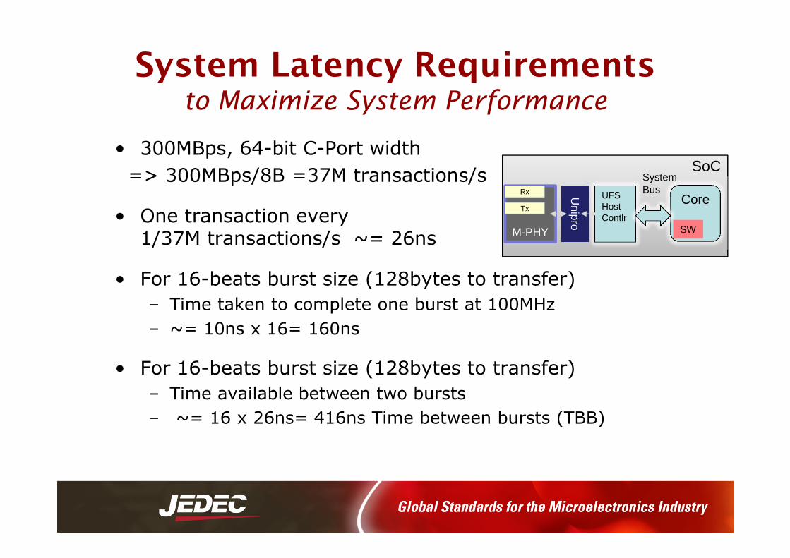
• 300MBps, 64-bit C-Port width
=> 300MBps/8B =37M transactions/s
• One transaction every 1/37M transactions/s ~= 26ns
• For 16-beats burst size (128bytes to transfer)
– Time taken to complete one burst at 100MHz
– ~= 10ns x 16= 160ns
• For 16-beats burst size (128bytes to transfer)
– Time available between two bursts
– ~= 16 x 26ns= 416ns Time between bursts (TBB)
SoC
Unipro
M-PHY
Tx
Rx UFS HostContlr
Core
SystemBus
SW

Configurable and Scalable Parameters Assist in Meeting Throughput
• To achieve required throughput
– Burst length (2…to 32)
– FIFOs / buffer sizes
– Data bus widths (currently 64, scalable to 128)
– Number of outstanding requests
– Group acknowledge SoC
Unipro
M-PHY
Tx
Rx UFS HostContlr
Core
SystemBus
SW

Sample UFS Setup for Throughput Measurement
• AXI latency =100-200 ns
• FIFO sizes =96
• Outstanding request = 4
• Hclk=200MHz; SymbolClk=150MHz
• Transfer size in bytes = 32768
• Number of RTTs =1
• Vary the number of PRD entries from 1,8,16,32,64
• Performance is measured from door bell setup to door bell clear for Gear2 Lane1

UFS E2E Throughput ResultsMultiple PRD Entries
0
20
40
60
80
100
120
140
160
180
1 2 3 4 5
Series1
Series2Read
1 16 32 64
End-t
o-E
nd T
hro
ughput
----
----
>M
Bps
Number of PRD Entries ----------------->
Write
8

UFS Host Solution to Future Proof Your Design

Future Speeds Demand Scalable IP Feature
• Future versions of the UFS Specification can demand higher throughput
– G3L2, G4L1
– G3L4, G4L2
• Scalable UFS Host Controller IP features
– Without compromising on latency and operating frequency
• 128/256-bit data bus width
• Higher number of outstanding RTTs
• Out-of-order execution granularity on system bus side

Future Proofing UFS Host Controller IP Design
• UFS host solution compliant with latest JEDEC Universal
Flash Storage (UFS) standard and JEDEC UFS host
controller interface specification
• Integrated with UniPro controller, compliant with latest
MIPI Alliance UniPro specification
• Single traffic class
• Supports M-PHY v3.0 and access to attributes
• Low-power operation, small area, and low latency
• Synopsys Solution is deployed in UFS Host and Device ICs
•

Close Collaboration Between Companies Developing UFS is Key
UFS Host and MIPI UniPro IP Interoperability Demo
Video at: http://www.synopsys.com/IP/Pages/designware-ip-mipi-videos.aspx
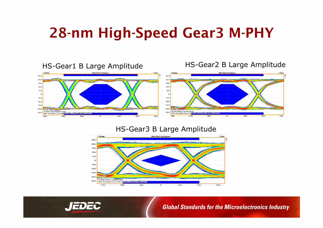
28-nm High-Speed Gear3 M-PHY
HS-Gear1 B Large Amplitude
HS-Gear3 B Large Amplitude
HS-Gear2 B Large Amplitude

Achieving High UFS Host Throughput for System Performance
Software
Verification
Controllers
PHYs
Boards
System-Level Interoperability
• Meet end-to-end throughput requirements
• Understand IP design considerations
• Meet system latency requirements
• Set configurable and scalable parameters
• Collaborate with proven UFS IP supplier

THANK YOUwww.synopsys.com/mipi