achieving excellence in cataract surgery...achieving excellence in cataract surgery a step-by-step...
TRANSCRIPT

AchievingExcellenceinCataractSurgery
A Step-by-Step Approach
Editedby
D. MichaelColvard,MD,FACSClinicalProfessorofOphthalmology
DohenyEyeInstituteKeckSchoolofMedicine
UniversityofSouthernCaliforniaLosAngeles,CA
MedicalDirectorofColvardEyeCenterEncino,CA
This project made possible through a grant from AMO.
Copyright © 2009 by D. Michael Colvard, MD, FACS.
Cover image of the Advanced Medical Optics ZCB00 single-piece acrylic IOL and the MicroSurgical Technologies bimanual irrigation/aspiration system courtesy of D. Michael Colvard, MD, FACS.
All rights reserved. No part of this book may be reproduced, stored in a retrieval system, or transmitted in any form or by any means, electronic, mechanical, photocopying, recording, or otherwise, without written permission from the editor, D. Michael Colvard, MD, FACS, except for brief quotations em-bodied in critical articles and reviews.
The procedures and practices described in this book and the companion DVD should be implemented in a manner consistent with the professional standards set for the circumstances that apply in each specific situation. Every effort has been made to confirm the accuracy of the information presented and to correctly relate generally accepted practices. The authors and editor cannot accept responsibility for errors or exclusions or for the outcome of the material presented herein. There is no expressed or implied warranty of this book or information imparted by it. Care has been taken to ensure that surgi-cal techniques, drug selection, and dosages are in accordance with currently accepted/recommended practice. Due to continuing research, changes in government policy and regulations, and various effects of drug reactions and interactions, it is recommended that the reader carefully review all materials and literature provided for each drug, especially those that are new or not frequently used.
Printed in the United States of America.

DedicationTo Drs. Richard Kratz and Thomas Mazzocco,
whose unwavering commitment to innovation, instruction, and patient care has benefited all of ophthalmology, and in turn helped each of us to be better physicians.
ContentsDedication ............................................................................................................................................................ iiiAcknowledgments .................................................................................................................................................. viiAbout the Editor .................................................................................................................................................... ixContributors ......................................................................................................................................................... xiPreface ............................................................................................................................................................... xiiiForeword by Peter J. McDonnell, MD .............................................................................................................. xviiIntroduction ........................................................................................................................................................ xix
Chapter 1: Local Anesthesia for Cataract Surgery .......................................................................................... 1 Rom Kandavel, MD
Chapter 2: Incisions ........................................................................................................................................ 11 D. Michael Colvard, MD, FACS
Chapter 3: Capsulorrhexis .............................................................................................................................. 19 Howard V. Gimbel, MD, MPH, FACS, FRCSC
Chapter 4: Hydrodissection and Hydrodelineation ....................................................................................... 27 I. Howard Fine, MD; Richard S. Hoffman, MD; and Mark Packer, MD, FACS
Chapter 5: Phaco Techniques Part A: Disassembling the Nucleus—An Overview ................................................................... 33 D. Michael Colvard, MD, FACS
Part B: Divide and Conquer ........................................................................................................ 35 D. Michael Colvard, MD, FACS
Part C: Phaco Chop Techniques ................................................................................................. 38 David F. Chang, MD
Part D: Bimanual Vertical Chop Technique ................................................................................ 49 Mark Packer, MD, FACS; I. Howard Fine, MD; and Richard S. Hoffman, MD
Chapter 6: Managing the Broken Posterior Capsule ...................................................................................... 53 David F. Chang, MD
Chapter 7: Management of the Small Pupil ................................................................................................... 59 Robert H. Osher, MD, and James M. Osher, MD
Chapter 8: The Phaco Machine: Understanding the Equipment to Take Advantage ................................... 67 of Contemporary Phaco Techniques William J. Fishkind, MD, FACS

Chapter 9: Setting Phaco Parameters .............................................................................................................77 Mark Packer, MD, FACS; I. Howard Fine, MD; and Richard S. Hoffman, MD
Chapter 10: Foldable Intraocular Lens Implantation ........................................................................................ 81 Richard S. Hoffman, MD; I. Howard Fine, MD; and Mark Packer, MD, FACS
Chapter 11: Understanding the Clinical Behavior of Ophthalmic Viscoelastic Devices ................................ 91 D. Michael Colvard, MD, FACS
Chapter 12: Intraocular Lens Materials and Design ........................................................................................ 95 Oliver Findl, MD, MBA
Chapter 13: Aspheric Intraocular Lenses ....................................................................................................... 109 Y. Ralph Chu, MD
Chapter 14: Capsular Tension Rings ...............................................................................................................115 Patrick J. Riedel, MD, and Thomas W. Samuelson, MD
Chapter 15: Preventing Postoperative Infection and Inflammation ............................................................... 123 Nick Mamalis, MD
Chapter 16: Optimizing Refractive Outcomes Part A: Biometry and Intraocular Lens Power Calculation ........................................................131 H. John Shammas, MD
Part B: Limbal Relaxing Incisions ............................................................................................. 136 Eric Donnenfeld, MD, and Renée Solomon, MD
vi Contents
Few calls are dreaded more than the one that 17 of my colleagues received last year. That call was mine, asking each of them if they would be kind enough to write a chapter for a new textbook. Early in one’s career, one might reasonably imagine that it would be flattering to be asked this. Certainly the invita-tion implies a certain level of recognition and esteem, but this request presented to an overworked surgeon whose reputation is already well established is, in all honesty, seldom welcomed. Writing a chapter for a new textbook is hard work with little upside. The effort occupies hours of what little “free” time the surgeon may have, he or she is guaranteed to be paid absolutely nothing, and, for the most part, all of the effort is lost in anonymity. One’s name on a list of contributors—that’s about it.
So why did all 17 of these people agree to take on this project? I would like to think some of it was out of friendship. I am certain that this played a small role, but the major motivation, I think, is that everyone believed in the project and wanted to be a part of it. This is a textbook written specifically for residents in training and young ophthalmologists who want to become bet-ter cataract surgeons. Every one of the contributors was at one time a young cataract surgeon, hoping to
become a better one. Every one of us was once helped by teachers and mentors to whom we will always be grateful. Every one of us wants to give back a little and honor those who helped us by passing forward what we have learned. I think it’s as simple as that.
I want to express my deepest gratitude to each one of the selfless physicians who worked so hard to make this text the great success that it is. And my special thanks goes out to the hardy few who went the extra mile—those who not only accepted the burden but truly seemed to relish it. To Howard Fine, who helped tremendously with the early planning of the text (including choosing the title); to Mark Packer and David Chang, who actually volunteered to do more work than I asked of them; and to Richard Hoffman, who did a spectacular job, both in the text and in the video supplement, painstakingly itemizing the loading and insertion techniques of all the major IOLs in use today.
My gratitude and thanks also goes out to Debra Toulson and Jennifer Cahill of SLACK Incorporated, both for their patience in putting up with me over the past 6 months and for their expert and conscien-tious efforts which have allowed this text to become a reality.
Acknowledgments

D. Michael Colvard, MD, FACS, was born in Atlantaand completed a combined undergraduate- MD pro-gram at Emory University, where he was Phi Beta Kappa and Alpha Omega Alpha. He completed a resi-dency in ophthalmology at the Mayo Clinic in 1978 and an anterior segment fellowship with Richard P. Kratz, MD, in 1979.
Dr. Colvard is presently in private practice in Encino, California, where he specializes in lens-based surgery. He has been on the clinical staff at the Doheny Eye Institute since 1981. He received the Honor Award from the American Academy of Ophthalmology in 1994 and has been selected as one of America’s Top Ophthalmologists and one of America’s Top Doctors.
Dr. Colvard has published widely in the ophthalmic literature and is the new technology editor for Review
of Ophthalmology. He has been the medical monitor for a number of Food and Drug Administration clinical studies involving new intraocular lens technologies and presently serves as the medical monitor and con-sultant to several ophthalmic companies. He holds a number of patents for ophthalmic devices and was the developer of the Colvard Pupillometer, a device widely used in refractive surgery around the world.
In addition, Dr. Colvard is the founder and medi-cal director of the Friends of Vision Foundation, an organization supporting medical charities in third-world countries, and is on the Board of Directors of SEE International. He has been active as a volunteer cataract surgeon in underdeveloped countries the past 20 years.
AbouttheEditor

ContributorsDavid F. Chang, MD (Chapters 5, 6)Clinical Professor of OphthalmologyUniversity of California, San FranciscoSan Francisco, CA
Y. Ralph Chu, MD (Chapter 13)Clinical Professor of OphthalmologyJohn A. Moran Eye InstituteUniversity of UtahAdjunct Professor of OphthalmologyUniversity of Minnesota
Eric Donnenfeld, MD (Chapter 16) Founding Partner Ophthalmic Consultants of Long Island Clinical Professor of OphthalmologyNew York University Medical Center Trustee Dartmouth Medical School
Oliver Findl, MD, MBA (Chapter 12)Consultant Ophthalmic SurgeonMoorfields Eye HospitalLondon, United Kingdom
I. Howard Fine, MD (Chapters 4, 5, 9, 10)Clinical Professor of OphthalmologyCasey Eye InstituteOregon Health & Science UniversityPortland, ORDrs. Fine, Hoffman & Packer, LLCEugene, OR
William J. Fishkind, MD, FACS (Chapter 8)Clinical Professor of OphthalmologyJohn A. Moran Eye InstituteUniversity of UtahClinical Instructor of OphthalmologyUniversity of Arizona
Howard V. Gimbel, MD, MPH, FACS, FRCSC (Chapter 3)Professor and ChairmanDepartment of OphthalmologyLoma Linda UniversityLoma Linda, CAMedical DirectorGimbel Eye CentreCalgary, Alberta, Canada
Richard S. Hoffman, MD (Chapters 4, 5, 9, 10)Clinical Associate Professor of OphthalmologyCasey Eye InstituteOregon Health & Science UniversityPortland, ORDrs. Fine, Hoffman & Packer, LLCEugene, OR
Rom Kandavel, MD (Chapter 1)Clinical Instructor Department of OphthalmologyUniversity of California, IrvineIrvine, CAAttending SurgeonColvard Eye CenterEncino, CA
Nick Mamalis, MD (Chapter 15)Professor of OphthalmologyDirector, Intermountain Ocular Research CenterDirector, Ocular PathologyJohn A. Moran Eye CenterSalt Lake City, UT
James M. Osher, MD (Chapter 7)Resident in OphthalmologyUniversity of CincinnatiCollege of Medicine
Robert H. Osher, MD (Chapter 7)Professor of OphthalmologyUniversity of CincinnatiCollege of MedicineMedical Director EmeritusCincinnati Eye Institute
Mark Packer, MD, FACS (Chapters 4, 5, 9, 10)Clinical Associate Professor of OphthalmologyCasey Eye InstituteOregon Health & Science UniversityPortland, ORDrs. Fine, Hoffman & Packer, LLCEugene, OR
Patrick J. Riedel, MD (Chapter 14) Partner, Minnesota Eye Consultants, PAAssistant Clinical Professor of Ophthalmology University of Minnesota Attending SurgeonPhillips Eye InstituteMinneapolis, MN
Thomas W. Samuelson, MD (Chapter 14) Attending SurgeonMinnesota Eye Consultants Phillips Eye InstituteAdjunct Associate ProfessorUniversity of Minnesota Minneapolis, MN
H. John Shammas, MD (Chapter 16)Clinical Professor of OphthalmologyKeck School of MedicineUniversity of Southern California Los Angeles, CAMedical DirectorShammas Eye Medical CenterLynwood, CA
Renée Solomon, MD (Chapter 16) Cornea, External Disease, Refractive Surgery SpecialistPrivate Practice New York, NY
xii Contributors

I realize that you have opened this text to learn phacoemulsification and that you are anxious to get on with it. Yet something compels me to ask you to slow down, if only for a moment. Before we hurry ahead, I need to tell you where we came from and how we got to the place we are today.
When I was a resident, the best that ophthal-mology had to offer a cataract patient was a bloody operation, a painful eye, and a lifetime of aphakia. We operated with loops, not microscopes, and made a 180-degree incision while an assistant surgeon held asilk retraction suture placed through the cornea. Thecornea was folded back on itself, allowing the surgeonto place a cryoprobe on the surface of the cataract. Alarge ice ball formed, the zonules were “gently” broken,and the entire lens, capsule and all, was delivered. If novitreous followed the lens, we congratulated ourselvesand proceeded to quibble about how many sutureswere needed. Should we use five or seven? The suturematerial was so large the knots could not be buried.
In the 1960s and much of the 1970s, this intra-capsular cataract extraction was hailed as the “perfect” procedure by experts of the day. Countless lectures were given, describing seemingly important refine-ments in this procedure, and there was general agree-ment, especially in academic institutions, that cataract surgery had reached its ultimate zenith. Those with ideas to the contrary were not welcomed. Most unwel-comed of all was Charles Kelman.
Kelman came upon the idea of phacoemulsifica-tion while sitting in a dental chair, having his teeth cleaned. It occurred to him that the same ultrasonic energy used to remove tartar could be used to remove the nucleus of a cataractous lens.
Kelman’s first phacoemulsification instruments were clumsy and difficult to use. Techniques for per-forming phaco were in their infancy, and the early complication rates, including “dropped nucleus” and corneal decompensation, were very high. There were at that time no effective instruments or techniques for retrieving the nucleus from the vitreous cavity, and eyes with retained nuclear material often progressed to phthisis. To help prevent this terrible complication, Kelman advocated subluxing the nucleus into the ante-rior chamber.1
In the early machines, the fluidics was very primi-tive, and high levels of ultrasonic energy were needed to emulsify the nucleus. The role of the endothelium in corneal health was poorly understood, and viscoelastic materials had yet to be developed. Eyes undergoing phacoemulsification in those days were frequently “lost” due to corneal decompensation, and Kelman’s new method for cataract surgery was rejected by vir-tually everyone. Kelman was seen as reckless by most surgeons and was personally reviled by many. To his assistance came a handful of surgeons who saw both the potential of Kelman’s ideas and the necessity of developing safer techniques for the new procedure.
Most ophthalmologists of that era operated with only one hand. With intracapsular surgery only one hand is needed to engage the nucleus and lift it out of the anterior chamber. Richard Kratz was one of the first surgeons to realize that phacoemulsification need-ed a new and innovative approach, a “bimanual tech-nique.” He understood the need to control the nucleus to prevent complications. Kratz devised techniques for tipping the proximal aspect nucleus out of the capsular bag and bringing it into the iris plane. This was accom-plished by introducing a second instrument through a side port incision. Held in this position, the nucleus could be emulsified with less risk of damage to the pos-terior capsule and less trauma to the corneal endothe-lium.2 The “bimanual approach” was quickly adopted by “early adapters” in the mid-1970s. By the late 1970s and early 1980s, hundreds of surgeons came to learn the new technique for phacoemulsification from Kratz. They returned to their practices to perform phaco-emulsification with greater safety, and, gradually, the procedure began to become more popular.
Monumental improvements in intraocular lens (IOL) technology were beginning to occur simultane-ously with the advances in phacoemulsification tech-niques. Efforts to combine anterior chamber and iris-supported IOLs with intracapsular surgery had proven largely unsuccessful. The introduction of the posterior chamber IOL by Steve Shearing in 19773 led to a reviv-al in extracapsular surgery. In the 1950s, extracapsular surgery had been abandoned in favor of intracapsular surgery because of problems of retained cortex and postoperative inflammation. With the advent of the
Preface

operating microscope and improvements in hand-held aspiration-irrigation systems, standard extracapsular surgery became much “cleaner.” This reduction in postoperative inflammation with the new standard extracapsular methods and the maintenance of a pos-terior capsule that provided support for Shearing’s new posterior chamber IOL suddenly made extracapsular surgery much more appealing to surgeons.
Shearing’s innovation was a change that made a huge difference in ophthalmology. Cataract surgery skyrocketed in popularity with the introduction of the posterior chamber IOL. Like phacoemulsification, pos-terior chamber lenses were initially rejected by many as inherently dangerous. The great fear was that posterior chamber IOLs would ultimately float in the vitreous cavity, but as positive experience with the new lenses increased and long-term success became established, this new IOL technology was universally embraced.
By the mid-1980s, there were two camps of poste-rior chamber lens users: those who performed standard extracapsular surgery and inserted the lenses through an 8- to 11-mm incision, and those who performed phacoemulsification and then enlarged the phaco inci-sion to 6 mm in order to implant the IOL. All IOLs at this time were made of polymethylmethacrylate (PMMA). Conventional extracapsular surgeons in the mid-1980s were very much in the majority. They saw little advantage in adopting phacoemulsification with all of its inherent difficulties and challenges as long as the incision needed to be enlarged for IOL insertion.
Thomas Mazzocco changed this. The “Mazzocco Taco,” a plate-shaped IOL made of silicone, was the first IOL designed to be rolled and inserted through an incision smaller than 6 mm.4 Many surgeons believed only in the sanctity of PMMA and doubted that a foldable material such as silicone would remain bio-logically inert or that it would remain clear over the course of time. Fortunately, the detractors, once again, were wrong. With the eventual development of a fold-able IOL that could be placed through an unenlarged 3-mm phaco incision, the advantages of small incision surgery were finally realized.
The foundations were now in place for the steady evolution in materials and techniques that have made phacoemulsification one of the safest and most elegant procedures in medicine today.
David Miller and Roger Stegmann introduced sodium hyaluronate to ophthalmology in the late 1970s5 and over the past three decades continuous improvements in ophthalmic viscoelastic devices have added greatly to the safety of cataract surgery.
Topical anesthesia was reintroduced to modern cataract surgery by Richard Fichman in the late 1990s6 and, to the surprise of most ophthalmologists, both retrobulbar and peribulbar injections of anesthetics were found to be largely unnecessary with the new surgical techniques.
Innovations by Michael McFarland,7 Paul Ernest,8 and Howard Fine9 in incision construction have allowed us to design better, stronger incisions, some of which no longer require sutures.
The can opener capsulotomy, the age-old main-stay of extracapsular surgery, was replaced by Howard Gimbel and Thomas Neuhann with the continuous curvilinear capsulotomy in the early 1990s.10 This innovation resulted in greater stability of the capsular bag during phacoemulsification and improved the cen-tration of IOLs postoperatively, but its introduction led to other challenges. The nucleus of a dense cataract could no longer be tipped easily into the pupillary plane for emulsification. New techniques had to be devel-oped for disassembling the nucleus within the capsular bag. Howard Gimbel11 and John Shepherd12developed “divide and conquer” techniques in the early 1990s, followed soon by Kunihiro Nagahara13 who intro-duced the first of the many chopping techniques now used widely by surgeons all over the world. These techniques, which all require the ability to move the nucleus within the capsular bag without placing undue stress on the zonular support of the capsule, were made possible by the development of hydrodissection and hydrodelineation techniques pioneered by Aziz Anis14 and Howard Fine.15
IOL technology has continued to advance with lens edge configurations that delay the onset of capsu-lar opacification and lens optics that improve the qual-ity of vision through aspheric design. Capsular tension rings now reduce the risks of capsular destabilization during our most challenging cases.
Last, but certainly not least, phacoemulsification technology has constantly improved with innova-tions in fluidics, power control, and duty cycles. These improvements in phacoemulsification provide the surgeon with a level of control and safety that even Charles Kelman could not have imagined. What comes next? What will be the direction of change that makes surgery safer, easier, more reliable, and more efficient?
Thirty-five years ago, it would have been impos-sible for any one person to guess where the collective genius of a generation of eye surgeons was about to take us. No one knew then what the future would bring, and no one knows now. Only one thing is certain. Those of
xiv Preface

you who are just beginning to learn phacoemulsifica-tion today will be part of that future. You are the next generation of innovators. Your challenge is to resist the notion that everything worthwhile has been discov-ered, that all the obstacles have been surmounted, and that there is nothing left to do. You are our future and there will be much left for you to do.
RefeRences1. Kelman CD. Phacoemulsification and aspiration—a new
technique of cataract removal: a preliminary report. Am J Ophthalmol. 1967;64:23-35.
2. Kratz RP, Colvard DM. Kelman phacoemulsification in theposterior chamber. J Cataract Refract Surg. 1979;86:1983-1984.
3. Shearing SP. Mechanism of fixation of the Shearing poste-rior chamber intra-ocular lens. Contact Intraocular Lens Med J.1979;5:74-77.
4. Mazzocco T. 6 mm optic for a 3 mm wound. American Intra-ocular Lens Society, US Intraocular Lens Symposium; NewOrleans, LA; March 1983.
5. Balazs EA, Miller D, Stegmann R. Viscosurgery and the useof Na Hyaluronate in intraocular lens implantation. Present-ed at: the International Congress and First Film Festival on
Intraocular Implantation; Cannes, France; 1979.6. Fichman RA. Use of topical anesthesia alone in cataract sur-
gery. J Cataract Refract Surg. 1996;22:612-614.7. McFarland MS. Surgeon undertakes phaco, foldable IOL se-
ries sans sutures. Ocular Surg News. 1990;8(5):1,15.8. Ernest PH, Lavery KT, Kiessling LA. Relative strength of
scleral corneal and clear corneal incisions constructed in ca-daver eyes. J Cataract Refract Surg. 1994;20:626-629.
9. Fine IH. Self-sealing corneal scleral tunnel incision for small-incision cataract surgery. Ocular Surg News. 1992;May 1.
10. Gimbel HV, Neuhann T. Development, advantages, andmethods of the continuous curvilinear capsulorhexis. J Cata-ract Refract Surg. 1991;17:110-111.
11. Gimbel HV. Trough and crater divide and conquer nucleo-fractis techniques. Euro J Implant Refract Surg. 1991;3:123-126.
12. Shepherd JR. In situ fracture. J Cataract Refract Surg.1990;16:436-440.
13. Nagahara K. Phaco chop film. Presented at: InternationalCongress on Cataract, IOL, and Refractive Surgery. Ameri-can Society of Cataract and Refractive Surgeons; Seattle,WA; May 1993.
14. Anis A. Understanding hydrodelineation: the term and re-lated procedures. Ocular Surg News. 1991;9:134-137.
15. Fine IH. Cortical cleaving hydrodissection. J Cataract Refract Surg. 1992;18:508-512.
Preface xv

ForewordThis excellent text serves an important need in
furthering the “science” of cataract surgery. The his-tory of progress in surgery, in general, contrasts in many ways with the rest of medicine. The initial “bar-ber surgeons” of England were looked down upon by the elitist and self-declared medical intellectuals who called themselves physicians. In contrast to the per-ception of surgery as a crude assault on the body, the tools of the physicians included observation, dietary manipulation, pharmacologic therapy, and scientific study. Surgeons learned their crafts via apprenticeships and accumulated anecdotal experience, but “medicine” was a science.
This legacy persisted for quite a while. Prospective, randomized, controlled clinical trials became routine in the evaluation of new proposed medical therapies. But rarely was this methodology embraced by surgeons, who would declare preeminence of their own surgical techniques after reporting small case series in which no control group was included. In the United States, a group of ophthalmologists actually sued in an effort to prevent the National Institutes of Health from carry-ing out a prospective study of one eye operation.
Early in my own career, it was common to hear interesting expressions from surgeons such as “in my hands.” In at least some cases, this was a mechanism for explaining away a lack of replication of claimed outcomes by other surgeons or medical centers. I have witnessed surgeon innovators ridiculing surgeons in the audience who described complications after try-ing the new surgical procedure, complications that the innovator claimed could never occur. “Perhaps you should go back and repeat your residency if you cannot perform a simple operation,” said one guest lecturer to a skilled local ophthalmic surgeon in California who did not see the same uniformly wonderful results in his patients. With the passage of time, it has become clear to me that in every case the observant practitioner was correct, and the indignant surgeon-innovator was too personally invested in his or her work to be objective. Could we give credence to an internist claiming that a drug works better “in my hands” than in those of another internist, or that an internist in the audience who reports an adverse event from a drug must be incompetent? Surgical texts for most of the 20th cen-
tury were typically beautifully illustrated testaments to the surgeon-author’s skill and dexterity, but references to the peer-reviewed literature, data, and statistical analysis supporting the author’s assertions were com-monly minimal or altogether absent.
Fortunately the field has evolved, and the term surgical science is no longer an oxymoron. Prospective controlled trials comparing surgical interventions and devices are no longer rare, and the claims from the podium of charismatic surgical “thought leaders” are no longer routinely accepted as valid substitutes for objective data.
At the same time, our society is tasking surgeons in general and ophthalmologists in particular with figur-ing out how to do more surgery, with better outcomes and at lower costs. The looming demographic tidal wave of the baby boomer generation has led ophthal-mic manpower studies to predict a 30% undersupply of ophthalmologists within a decade or two in the United States. The prevalence of cataracts and other age-related eye diseases will increase dramatically; the number of ophthalmic surgeons will not change appre-ciably. Not content to simply see our profession deal with this volume, our society demands that we reduce the cost of this care, improve the results (eg, eliminate the need for corrective eye wear for distance, near, and intermediate vision postoperatively after cataract surgery), and reduce the risks of endophthalmitis and other complications. In short, ophthalmic surgeons will need to do more with less.
We are also asked to change how we transform new ophthalmology residents into capable surgeons. The apprenticeship model of “see one, do one, teach one” is being replaced by a more rigorous approach of communicating the underlying scientific principles of surgery, breakdown of multistep procedures into their component parts, and “certification” of trainees as having mastered each of these steps. Pedagogical scientists tell us that this will accelerate the progress of new surgeons, more quickly identify strengths and weaknesses of budding surgeons so that deficiencies can be quickly corrected, reduce the likelihood of complications during the early part of the learning curve, and ensure society that the new surgeons we train possess the required competencies.

This text reflects the positive trends in how we are coming to embrace the science of ophthalmic surgery. The physics that drives our cataract surgical instru-ments, the detailed exploration of techniques for each step of the procedure, the optics of vision correction, and the outcomes data that speak to the quality of our interventions are all beautifully illustrated. I believe this will prove a valuable resource for beginning sur-geons who will want to immerse themselves in the
details of surgical technique before performing those techniques on their first patients, as well as for more experienced surgeons looking to continuously improve the outcomes for their patients.
Peter J. McDonnell, MDDirector of The Wilmer Eye Institute
Johns Hopkins University School of MedicineBaltimore, MD
xviii Foreword
IntroductionModern cataract surgery is one of medicine’s fin-
est achievements. No procedure today is more gentle, safe, and successful; more important to the quality of life and well-being of patients; or more beneficial to society as whole than is phacoemulsification. The pro-cedure is also a marvel to behold. It is an art form, and, once learned well, it is a joy to perform.
In the hands of a skilled surgeon, phacoemulsifica-tion is a masterful ballet of efficiency and grace. Each precise and carefully practiced step leads fluidly to the next. For a number of years, I have had the pleasure of training a wonderful group of young resident surgeons in phacoemulsification. This experience as a teacher and my own 30 years as a phaco surgeon have taught me the value of understanding phacoemulsification as a series of thoughtfully considered steps. Each step of phacoemulsification must be understood thoroughly, learned perfectly, and practiced repeatedly before the procedure can be executed with consistent proficiency.
Phacoemulsification is unforgiving. If there is a stumble on any one step, the next step becomes more difficult and things begin to go badly. When each sequential step is performed well, however, the procedure seems to glide effortlessly and a magical thing occurs. The surgeon’s hands create something that is not only good but lovely to behold.
More than a dozen of the world’s finest surgeons have come together in this text to help you learn to perform phacoemulsification at its highest level. Each has chosen one or more aspects of the procedure and has carefully analyzed the steps that are critical to the successful performance of that part of the surgery. Whenever it is useful, the authors have also provided narrated video footage that illustrates the key instruc-tional points made in the text. This complete video reference should prove to be an invaluable resource as you learn to achieve excellence phacoemulsification.

�
In recent years, advances in cataract surgery have lead to greater levels of refractive precision, faster visual rehabilitation, and improved comfort and safety. Refinements in phacoemulsification techniques and intraocular lens (IOL) technology deserve much of the credit for these advances, but innovations in anesthe-sia, especially topical anesthesia, have also played an important role in improving outcomes and hastening visual recovery.
While topical anesthesia is favored by many sur-geons for the majority of their cases today, proper patient screening and careful preoperative planning are necessary in order to choose the best anesthesia for an individual patient. Mastery of all of the avail-able techniques—intracameral, topical, parabulbar (sub-Tenon’s), peribulbar, and retrobulbar anesthe-sia—along with an understanding of their advantages and disadvantages, is necessary in order to provide the highest level of care for all patients. The goal of this chapter is to define and describe the indications and techniques for each of these approaches.
Applied AnAtomyA basic knowledge of orbital anatomy is essential
to understand the effects and potential complications of orbital anesthesia.
Intraocular pressure may be elevated after the injection of even modest amounts of anesthetic into the orbit. The orbit has an average volume of 30 cc. A sudden increase in orbital volume associated with the injection of anesthetic results in the transmission of force anteriorly, causing compression of the globe.
The floor of the orbit is the shortest of the orbital walls and extends only 35 to 40 mm from the orbital rim. The 38-mm needle used in retrobulbar anesthesia, therefore, has the potential to damage the optic nerve in a significant percentage of the population.1
The abducens, oculomotor, and nasociliary nerves pass through the annulus of Zinn. The trochlear nerve enters outside of the annulus to supply the superior oblique. Placement of anesthetic within the intramus-cular cone, whose apex is the annulus of Zinn, typi-cally results in the paralysis of the oculomotor and the abducens but not the trochlear. The superior oblique is often spared, and cyclotorsion may still occur even with a well-placed retrobulbar injection.
Sensory innervation to the cornea and superonasal conjunctivae is provided by the nasociliary nerve that is within the muscle cone. The remaining conjunctival sensation is provided by the remaining branches of ophthalmic nerve (frontal and lacrimal) and two divi-sions of the maxillary nerve, which supply the lower
Chapter
Local Anesthesia forCataract Surgery
Rom Kandavel, MD
1

� Chapter 1
lid and conjunctiva (enters via the inferior orbital fora-men). All of these additional somatosensory nerves lie outside of the muscular cone. For this reason, a retro-bulbar block can still leave areas of the conjunctiva sensitive to pain and touch.
The dura surrounding the optic nerve is continu-ous with the dura of the brain. Inadvertent injection of anesthetic into the subdural space within the nerve, therefore, can result in brainstem anesthesia.
preoperAtive evAluAtionCareful patient screening is essential in order to
determine which form of anesthesia is best suited for an individual. A surgeon should develop a checklist to avoid missing data that can influence the choice of anesthesia. A history and physical examination, with review of medications, is an excellent starting point for evaluation. Particular attention should be given to the patient’s ability to communicate, lie flat and still, and follow directions. A history of congestive heart failure, chronic obstructive pulmonary disease, chronic bronchitis, claustrophobia, anticoagulation status, and use of alpha-blockers (tamsulosin) should be addressed with each patient.
Retrobulbar and peribulbar anesthesia generally provide excellent intraoperative pain control with the added benefit of complete or partial akinesia and visual block. General anesthesia may be utilized when generalized muscle paralysis is an additional factor to ensure surgical success. Topical anesthesia should be reserved for communicative and calm patients who
have no relevant comorbidities. The surgeon should be experienced and expecting a shorter surgery with-out anticipated complications or added procedures. Longer procedures that may require iris manipulation or scleral suturing may benefit from retrobulbar or peribulbar anesthesia for improved iris and ciliary body anesthesia. While most patients can lie still, some may not be able to follow directions and are not well suited for topical anesthesia. Patients who have psychiatric disease or other comorbidities that prevent them from lying still may be candidates for general anesthesia.
The information contained in Tables 1-1 and 1-2 can serve as general guidelines for anesthesia selec-tion. In some instances, reviewing the procedure and different anesthesia approaches with the patient is useful. This allows the patient to self-assess his or her preferences. The discussion also allows the patient to ask questions and develop greater comfort with the surgeon and surgery.
retrobulbAr AnesthesiAMultiple protocols have been published with a
common goal of improving the efficacy and safety of retrobulbar anesthesia. Complications arising from ret-robulbar anesthesia include retrobulbar hemorrhage, globe/nerve perforation, extraocular muscle injury, and brainstem anesthesia/death.2 Other disadvantages include the need for increased sedation, a postopera-tive eye patch, longer visual recovery, ptosis, chemosis, subconjunctival hemorrhage, and increased posterior pressure during surgery. The most feared complication
Table 1-1Contraindications to Local Anesthesia
RelativeTremorAnxietyClaustrophobiaChildrenPoor communication/language barrier/deafnessLong operative time
AbsoluteInability to cooperate (eg, schizophrenia, dementia)Uncontrolled coughing/movement disorder
Table 1-2Contraindications to Topical Anesthesia
RelativePhotophobiaAnxietyDeafnessLong operative time
AbsolutePoor communication/language barrier/deafnessCannot follow directionsInsufficient pain control (as in prior eye surgery)

Local Anesthesia for Cataract Surgery �
of retrobulbar injection, perforation of the globe, is more common with eyes of higher axial length and/or staphyloma.2
A well-placed retrobulbar block usually results in excellent akinesia and sensory block with some visual block also. As previously noted, motor nerves within the muscle cone, the abducens, oculomotor, as well as the sensory nasociliary nerve, are affected, but because the trochlear nerve passes outside the cone, superior oblique muscle innervation is usually spared and cyclo-torsion may still occur. Most surgeons supplement retrobulbar blocks with topical anesthesia to complete anterior segment anesthesia because portions of the trigeminal, which supply the conjunctiva and lid, also pass outside the muscle cone.
The goal of retrobulbar anesthesia is the place-ment of anesthetic into the intramuscular cone located behind the globe and anterior to the orbital apex. Structures traversed by the retrobulbar needle include the skin, orbital septum, periocular tissue/fat, and the intramuscular connective tissue. Structures to be avoided include blood vessels, extraocular muscles, the globe, and the optic nerve. The technique detailed below is designed to avoid these structures and give reliable and reproducible anesthesia. Each surgeon will develop personal amendments, but the basic tenets apply.
Injectable mixtures should include a total volume of 10 cc or less composed of 2% lidocaine without epinephrine mixed 50:50 with 0.75%. Note that this 50:50 mixture dilutes each component to half the original concentration. Some surgeons may prefer 4% lidocaine, if available, to yield a final effective concen-tration of 2% lidocaine. The addition of bupivacaine increases the duration of action. If hyaluronidase is available, it can also be added to the mixture to speed diffusion of the medication and improve akinesia and sensory block. Hyaluronidase can also decrease poste-rior pressure by causing the volume to distribute more quickly. Fifteen to 20 units of hyaluronidase per mL of solution can be used.
A 38-mm (1.5-inch) 23-gauge needle with a round-ed point (Atkinson) is preferred. A standard sharp point needle has the advantage of passing through tis-sues more easily with less discomfort, but the reduced sensory feedback during injection and higher potential for injury to ocular structures favors the Atkinson or blunt-tipped needle.3 A 10-cc syringe is also preferred over a 5-cc for better tactile control of injection pres-sure and enough volume to change needles and contin-ue with facial nerve blocks after retrobulbar injection using the same syringe.
Retrobulbar anesthesia is performed prior to sterile prep. The patient is positioned flat on the operative bed. At the level of the forehead, 1-inch silk, plastic, or paper tape can be used to secure the head to the table if an assistant is not available. Intravenous pro-pofol or Versed (Hospira, Lake Forest, IL) should be administered in conjunction with an analgesic, such as fentanyl, to help prepare the patient for injection. If propofol is used, time for the medication to take effect should be allowed. Testing the lack of orbicularis contraction by gently brushing the eyelashes can help verify adequate sedation.
Following surgery, the eye should be patched. This is because the retrobulbar block reduces sensation of the eye (which results in a reduced blink reflex), provides akinesia (which causes a transient diplo-pia), and reduces vision (which is frightening to the patient). The patch may be removed after 4 to 6 hours in patients who have received only lidocaine. When bupivacaine is used, the patch should remain for not less than 8 hours.
pArAbulbAr (sub-tenon’s) AnesthesiA
Some surgeons have adopted the technique of using a blunt-tipped cannula intraoperatively to inject the same anesthetic mixture. This is known as a para-bulbar block. Parabulbar blocks can be placed as a planned anesthesia or can be utilized intraoperatively if the patient is uncooperative or has inadequate pain control with topical/peribulbar anesthesia.
This technique avoids the hazards of a sharp needle placement into this space and is a safer alterna-tive to retrobulbar anesthesia, but it can also result in increased chemosis, subconjuctival hemorrhage, and incomplete anesthesia if the cannula is not advanced in the sub-Tenon’s space.4 Damage to the vortex veins has also been reported.5 Onset is rapid, but the added dis-section can add to operative time. The disadvantages such as the need for patching with delayed visual reha-bilitation apply, as with retrobulbar anesthesia.
peribulbAr AnesthesiAThe injection of anesthesia within the orbit with-
out directing the needle inside the muscle cone reduces the risk of damage to vital structures. The soft tissue, intramuscular septae are incomplete and allow for the diffusion of medication into the cone, resulting in akinesia and visual block, as well as sensory dein-nervation to the nasociliary and extraconal divisions

� Chapter 1
of first and second divisions of the trigeminal nerve. This technique relies on larger volumes (7 to 10 cc) and works best if supplemented by 500 units of hyal-uronidase. Sedation with propofol, as with retrobulbar anesthesia, is preferred.
Sensory block and akinesia are dependent on dif-fusion, therefore this technique requires reassessment of akinesia (if desired) after 5 to 7 minutes. If adequate medial rectus akinesia is not obtained, the peribulbar injection can be repeated using the same technique targeting the medial fat compartment. Up to 24% of patients will require this supplemental 3- to 5-cc block.6 The entrance site for the supplemental block is just nasal to the medial rectus, adjacent to the carun-cle, and parallel to the medial orbital wall in the same fashion as described above. Higher volumes overall are used, therefore orbital pressure is increased and ecchymosis and chemosis are more likely than with the retrobulbar block.7 Reports of retrobulbar hemorrhage and globe perforation have also been published but are less common. This technique has reported anesthetic pain control similar to retrobulbar placement, but has an improved safety profile.8 Overall, the advantages of peribulbar anesthesia should be weighed against the frequent need for supplemental anesthesia, incomplete akinesia, the larger volume of anesthesia, and longer time required for complete diffusion.
topicAl And intrAcAmerAl AnesthesiA
As phacoemulsification techniques have advanced, incision size has decreased, the need for iris manipula-tion has diminished, and operative time has lessened. These changes have resulted in a decrease in the need for complete akinesia, long duration of ocular anesthe-sia, and intensity of iris and ciliary body sensory block. Topical and intracameral anesthesia alone can provide adequate anterior segment anesthesia for noncomplex phacoemulsification with proper patient selection.9 Use in trabeculectomy, secondary sutured IOLs, and pterygium excision has also become more common.
Topical anesthesia avoids the systemic and ocular risks of the previously described modalities. In addi-tion, it allows for quick visual recovery. Monitored anesthesia care can be used, but surgery can also be performed without intravenous agents (discussed below). It should be noted that many surgeons who use retrobulbar or peribulbar block use topical and/or intracameral anesthetic in addition to help complete
the anterior segment sensory block. Communicative, calm, cooperative patients are candidates for topical anesthesia. Careful patient selection is important.
Multiple agents are available for topical anesthesia and include tetracaine 0.5% drops, Tetravisc 0.5% gel (Ocusoft, Richmond, TX), lidocaine 2% jelly, Xylocaine 4% (AstraZeneca, Wilmington, DE), and bupivacaine 0.75%. Topical agents are placed at least 5 to 10 minutes prior to surgery. They provide excellent intraoperative pain control and also allow the patient to have less discomfort from the Betadine prep prior to draping.
Drop preparations are generally administered in two to three repeated doses separated by 5 to 10 minutes. Gel preparations have the benefit of coating the eye without requiring repeated doses. If used prior to dilating agents, gels can interfere with absorption. Therefore, many surgeons place a liquid preparation such as proparacaine 0.5% or tetracaine drops first and then complete the dilation protocols. After the pupil is dilated and 5 to 10 minutes prior to entering the operating room, Tetravisc or lidocaine gel can be placed into the eye. Lidocaine gel can be more viscous and at times more difficult to place under the lids to anesthetize the superior and inferior conjunctiva and fornices.10 Tetravisc has an intermediate viscosity and therefore spreads like a liquid drop but also coats like a gel. Each surgeon should develop a simple, repro-ducible protocol for topical anesthesia that can be performed efficiently by the surgical staff. One other variant on this form of anesthesia includes soaking a sponge with both dilating and/or anesthetic drops (perilimbal anesthesia) and placing it in the inferior fornix for 10 to 15 minutes. Anecdotal reports suggest that soaked pledgets can deliver higher concentrations of both anesthetic and mydriatic medications, but the actual procedure of sponge placement can be more intrusive than drops alone.
Topical anesthesia alone may not provide adequate iris and ciliary body anesthesia. Therefore, many surgeons will supplement with intracameral 1% non-preserved lidocaine. After the initial paracentesis is created, approximately 0.5-cc nonpreserved lidocaine is instilled into the anterior chamber. Uncomplicated cataract surgery can be performed with topical anes-thesia alone, but prospective trials suggest an addition-al anesthetic benefit to intracameral lidocaine.11 This additional agent represents a very quick, extra step in cataract surgery. At 1% concentration, endothelial cell toxicity has not been demonstrated in humans.
Local Anesthesia for Cataract Surgery �
The additional anesthetic effect makes any iris touch or manipulation more comfortable. If a scleral sutured posterior chamber lens, pupil expansion device, or iris stretching is necessary, intracameral anesthesia can be a useful adjunct. Other agents such as epinephrine or phenylephrine can also be added to this intracameral solution. These and other techniques are discussed in other portions of this text.
FAciAl nerve blocksOccasionally, a patient may have difficulty with
relaxing his or her orbicularis oculi muscle. Many times this is anxiety related, other times it may be an idiosyncratic reflex specific to that individual. Psychiatric disease can be a risk factor. If intravenous agents fail to reduce squeezing, facial nerve blocks in combination with any of the anesthetic modalities above can allow the surgeon to have improved control. Generally, patients who require facial nerve blocks are good candidates for retrobulbar/peribulbar anesthesia because of associated Bell’s phenomenon. Facial nerve blocks can be performed at any portion of the extra-cranial course after it exits the stylomastoid foramen. The nerve gives off multiple branches as it courses from behind the ear over the angle of the mandible, penetrating the parotid gland and dividing into its ter-minal branches, including the temporal and zygomatic, which supply the orbicularis. Types of facial nerve blocks are differentiated by their location, and each has inherent advantages and disadvantages.
Careful placement of additional anesthetic in the inferior fornix and anterior lateral orbit as the needle is withdrawn during retrobulbar and peribulbar anes-thesia can also result in seventh nerve block in up to 88% of cases by continued diffusion.12 Although less reliable, this can obviate the need for a separate facial nerve block.
The Nadbath block is directed at the exit of the nerve at the stylomastoid foramen. Respiratory and vocal chord paralysis have been reported with inadver-tent injection into the jugular foramen.13-15 Prolonged facial nerve block has also been reported.15 This tech-nique avoids ecchymosis of the face and is less painful, but also can temporarily paralyze multiple divisions of the facial nerve.
The O’Brien is placed more distally just below the zygomatic arch, anterior to the tragus. This site can be more painful and can also cause paralysis of the lips and lower face in addition to the intended superior divisions.
The modified Van Lint targets the terminal branch-es at the lateral canthus and lid. This technique avoids the paralysis of the other divisions of the seventh nerve but can cause lid ecchymosis and edema.
Facial nerve blocks are best done with conscious sedation usually directly after retrobulbar or peribul-bar block while the propofol is still at maximal effect. The same 10-cc syringe can be used if appropriate by changing the needle to a conventional sharp point 1-inch 30-gauge or 27-gauge needle.
conscious sedAtion And GenerAl Anesthetic AGents
Cataract surgeons should possess a basic under-standing of common anesthetic agents. Many times feedback from the patient is only perceived and communicated to the surgeon intraoperatively. The surgeon may also better understand the needs of each patient, having treated him or her for many years, than the anesthesiologist present for the surgery. An understanding of the common medications and their relative analgesic, anxiolytic, and amnestic properties will allow the surgeon to help tailor preoperative plan-ning and intraoperative supplementation.
Monitored anesthesia care involves intravenous sedation and analgesia with noninvasive monitoring. This allows for less physical stress on the patient. The patient is able to respond to commands, facilitating surgery, and recovery is quicker. Conversion to gen-eral anesthesia is still possible. Commonly used single agents include opiates (fentanyl), benzodiazepines (midazolam), and propofol.
Propofol (Diprivan [AstraZeneca]) is a short-act-ing induction agent that provides temporary sedation without analgesia. Propofol can be used prior to ret-robulbar block placement. Although the block can be placed without propofol, this agent provides a short duration of deep sedation with amnesia. Testing lack of orbicularis contraction by gentle eyelash stimulation can be a helpful measure of adequate sedation prior to retrobulbar placement. Hypotension and temporary apnea are possible, therefore pulsoximetry and blood pressure monitoring are essential.
Fentanyl and midazolam (Versed) can be used alone or in conjunction. Fentanyl, a short-acting nar-cotic, provides analgesia with some mild anxiolysis. Midazolam is an excellent anxiolytic and can also have an amnestic effect. Midazolam is short acting, water soluble, and has no analgesic properties. Both have a quick onset of action and can be augmented dur-

� Chapter 1
ing surgery for added effect. Midazolam can have a disinhibiting effect that can result in a lack of patient cooperation. This disinhibition and confusion is more common in the elderly and quite rare in younger patients. In some circumstances, patients can attempt to sit up or remove their draping. Therefore, careful attention and communication with the patient and anesthesiologist during surgery should be maintained in order to continually assess patient comfort and mental status.
Cooperation with adequate pain and anxiety con-trol is the goal of every cataract surgery. The surgeon’s demeanor and communication can help supplement pharmacologic anesthesia. Some individuals may expe-rience pain but not alert the surgeon for fear of “inter-fering” with the surgery. It can be useful to briefly describe to the patient what to expect in the operating room and encourage him or her to verbally express discomfort so that added analgesia can be provided.
step-by-step ApproAch to retrobulbAr AnesthesiA
Step 1. Anesthetic Preparation. A 38-mm (1.5-inch) 23-gauge needle with a rounded point (Atkin-son) on a 10-cc syringe is preferred. Ten cc containing 2% lidocaine without epinephrine mixed 50:50 with 0.75% bupivacaine and 10 to 15 units hyaluronidase per cc (optional) can be used.
Step 2. Patient Position. The assistant should be pres-ent at the head of the bed, facing the feet, hold-ing the head securely with both hands. One finger can be used to lift the upper lid of the operative eye to allow the surgeon to visualize
the globe throughout the procedure (Figure 1-1). The surgeon should be on the same side of the bed as the operative eye. The lower eye lid skin should be cleaned with an alcohol swab.
Step 3. Needle Placement. The needle tip, bevel down, is advanced parallel to the orbital floor, entering at the lateral third of the inferior lid. The patient’s eye should be in primary position (Figures 1-2 and 1-3).
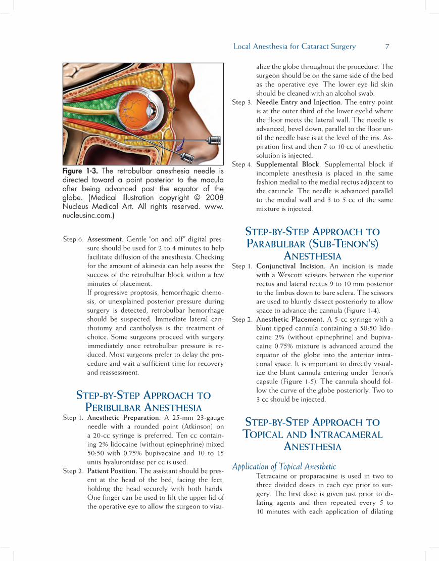
Step 4. Needle Advancement. The surgeon’s index finger can be used to palpate and displace the globe superiorly as the needle is positioned to create adequate space for the needle to pass inferior to the globe between the lateral and inferior rectus muscles. Resistance to the rounded needle can be noted when the orbital septum is reached. Once the needle has passed the equator of the globe (the halfway point of the needle should be at the level of the iris), the needle is then angled superior and slightly medial toward the muscular cone to a loca-tion posterior to the macula. A small amount of anesthesia can be injected as the needle is advanced.
Step 5. Entering the Muscle Cone and Injecting. Re-sistance and relief can be detected as the needle enters the muscle cone. The syringe plunger should be gently withdrawn to ensure a blood vessel has not been entered prior to injection. Depending on anticipated cone volume, 2.5 to 4.0 cc should be injected. An additional 1 to 2 cc can be injected as the needle is withdrawn.
Figure 1-1.Properpatientstabilizationandpositionforretrobulbar/peribulbaranesthesia.
Figure 1-2. The retrobulbar/peribulbar needleshould enter at the lateral one-third of the lowereyelid below the globe with the eye in primaryposition. Supplemental medial peribulbar blocksenterbetweenthecaruncleandmedialrectus.
Local Anesthesia for Cataract Surgery �
Step 6. Assessment. Gentle “on and off” digital pres-sure should be used for 2 to 4 minutes to help facilitate diffusion of the anesthesia. Checking for the amount of akinesia can help assess the success of the retrobulbar block within a few minutes of placement. If progressive proptosis, hemorrhagic chemo-sis, or unexplained posterior pressure during surgery is detected, retrobulbar hemorrhage should be suspected. Immediate lateral can-thotomy and cantholysis is the treatment of choice. Some surgeons proceed with surgery immediately once retrobulbar pressure is re-duced. Most surgeons prefer to delay the pro-cedure and wait a sufficient time for recovery and reassessment.
step-by-step ApproAch to peribulbAr AnesthesiA
Step 1. Anesthetic Preparation. A 25-mm 23-gauge needle with a rounded point (Atkinson) on a 20-cc syringe is preferred. Ten cc contain-ing 2% lidocaine (without epinephrine) mixed 50:50 with 0.75% bupivacaine and 10 to 15 units hyaluronidase per cc is used.
Step 2. Patient Position. The assistant should be pres-ent at the head of the bed, facing the feet, holding the head securely with both hands. One finger can be used to lift the upper lid of the operative eye to allow the surgeon to visu-
alize the globe throughout the procedure. The surgeon should be on the same side of the bed as the operative eye. The lower eye lid skin should be cleaned with an alcohol swab.
Step 3. Needle Entry and Injection. The entry point is at the outer third of the lower eyelid where the floor meets the lateral wall. The needle is advanced, bevel down, parallel to the floor un-til the needle base is at the level of the iris. As-piration first and then 7 to 10 cc of anesthetic solution is injected.
Step 4. Supplemental Block. Supplemental block if incomplete anesthesia is placed in the same fashion medial to the medial rectus adjacent to the caruncle. The needle is advanced parallel to the medial wall and 3 to 5 cc of the same mixture is injected.
step-by-step ApproAch to pArAbulbAr (sub-tenon’s)
AnesthesiAStep 1. Conjunctival Incision. An incision is made
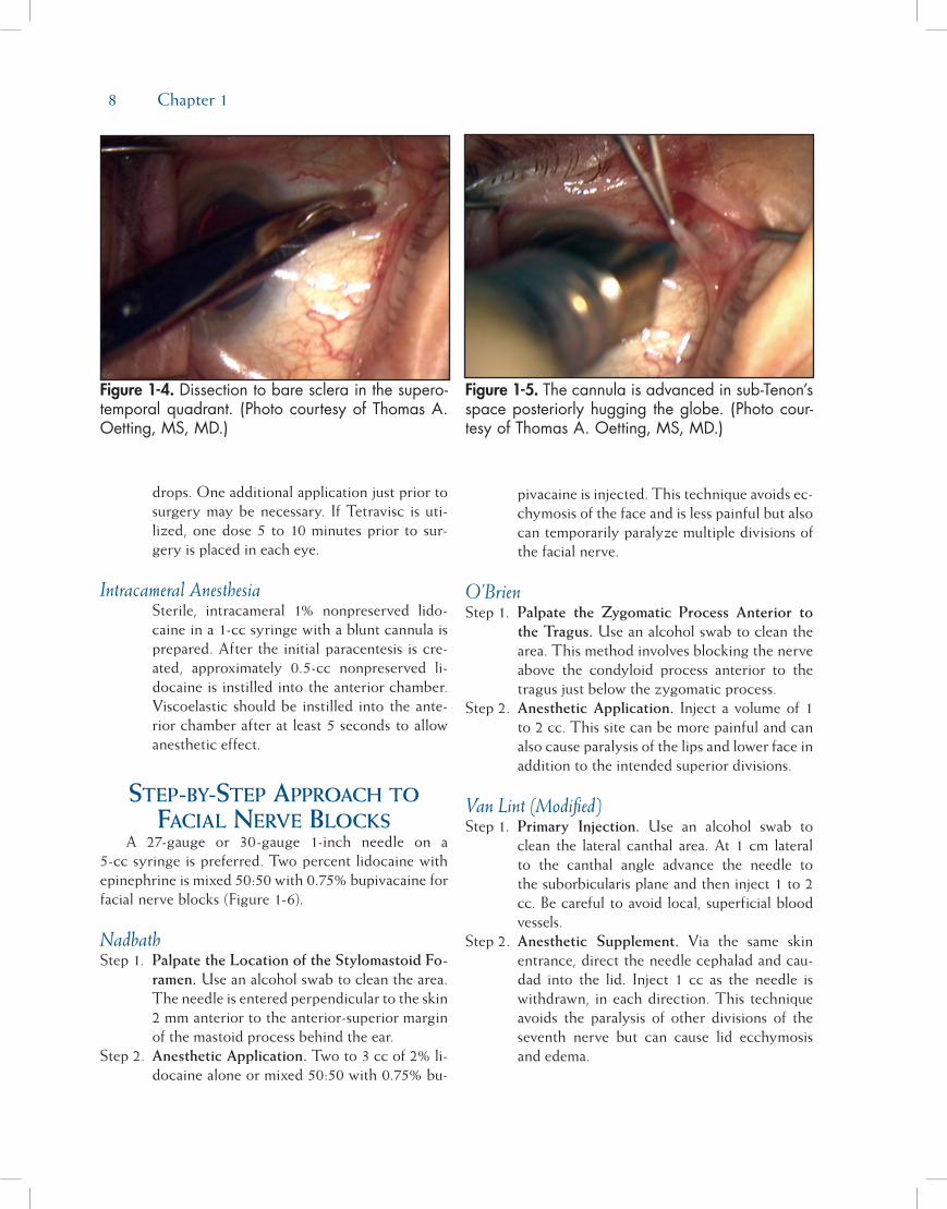
with a Wescott scissors between the superior rectus and lateral rectus 9 to 10 mm posterior to the limbus down to bare sclera. The scissors are used to bluntly dissect posteriorly to allow space to advance the cannula (Figure 1-4).
Step 2. Anesthetic Placement. A 5-cc syringe with a blunt-tipped cannula containing a 50:50 lido-caine 2% (without epinephrine) and bupiva-caine 0.75% mixture is advanced around the equator of the globe into the anterior intra-conal space. It is important to directly visual-ize the blunt cannula entering under Tenon’s capsule (Figure 1-5). The cannula should fol-low the curve of the globe posteriorly. Two to 3 cc should be injected.
step-by-step ApproAch to topicAl And intrAcAmerAl
AnesthesiA
Application of Topical AnestheticTetracaine or proparacaine is used in two to three divided doses in each eye prior to sur-gery. The first dose is given just prior to di-lating agents and then repeated every 5 to 10 minutes with each application of dilating
Figure 1-3. The retrobulbar anesthesia needle isdirected toward a point posterior to the maculaafter being advanced past the equator of theglobe. (Medical illustration copyright © 2008Nucleus Medical Art. All rights reserved. www.nucleusinc.com.)
� Chapter 1
drops. One additional application just prior to surgery may be necessary. If Tetravisc is uti-lized, one dose 5 to 10 minutes prior to sur-gery is placed in each eye.
Intracameral AnesthesiaSterile, intracameral 1% nonpreserved lido-caine in a 1-cc syringe with a blunt cannula is prepared. After the initial paracentesis is cre-ated, approximately 0.5-cc nonpreserved li-docaine is instilled into the anterior chamber. Viscoelastic should be instilled into the ante-rior chamber after at least 5 seconds to allow anesthetic effect.
step-by-step ApproAch to FAciAl nerve blocks
A 27-gauge or 30-gauge 1-inch needle on a 5-cc syringe is preferred. Two percent lidocaine withepinephrine is mixed 50:50 with 0.75% bupivacaine forfacial nerve blocks (Figure 1-6).
NadbathStep 1. Palpate the Location of the Stylomastoid Fo-
ramen. Use an alcohol swab to clean the area. The needle is entered perpendicular to the skin 2 mm anterior to the anterior-superior margin of the mastoid process behind the ear.
Step 2. Anesthetic Application. Two to 3 cc of 2% li-docaine alone or mixed 50:50 with 0.75% bu-
pivacaine is injected. This technique avoids ec-chymosis of the face and is less painful but also can temporarily paralyze multiple divisions of the facial nerve.
O’BrienStep 1. Palpate the Zygomatic Process Anterior to
the Tragus. Use an alcohol swab to clean the area. This method involves blocking the nerve above the condyloid process anterior to the tragus just below the zygomatic process.
Step 2. Anesthetic Application. Inject a volume of 1 to 2 cc. This site can be more painful and can also cause paralysis of the lips and lower face in addition to the intended superior divisions.
Van Lint (Modified)Step 1. Primary Injection. Use an alcohol swab to
clean the lateral canthal area. At 1 cm lateral to the canthal angle advance the needle to the suborbicularis plane and then inject 1 to 2 cc. Be careful to avoid local, superficial bloodvessels.
Step 2. Anesthetic Supplement. Via the same skin entrance, direct the needle cephalad and cau-dad into the lid. Inject 1 cc as the needle is withdrawn, in each direction. This technique avoids the paralysis of other divisions of the seventh nerve but can cause lid ecchymosis and edema.
Figure 1-4. Dissectiontobaresclerainthesupero-temporalquadrant. (PhotocourtesyofThomasA.Oetting,MS,MD.)
Figure 1-5. Thecannulaisadvancedinsub-Tenon’sspaceposteriorlyhuggingtheglobe. (Photocour-tesyofThomasA.Oetting,MS,MD.)

Local Anesthesia for Cataract Surgery �
reFerences1. Katsev DA, Drews RC, Rose BT. An anatomic study of ret-
robulbar needle path length. Ophthalmology. 1989;96:1221-1224.
2. Eke T, Thompson JR. Serious complications of local anaes-thesia for cataract surgery: a 1 year national survey in theUnited Kingdom. Br J Ophthalmol. 2007;91(4):470-475.
3. Waller SG, Toboada J, O’Connor P. Retrobulbar anesthesiarisk. Do sharp needles really perforate the eye more easilythan blunt needles? Ophthalmology. 1993;100(4):506-510.
4. Zafirakis P, Voudouri A, Rowe S, et al. Topical versus sub-Tenon’s anesthesia without sedation in cataract surgery.J Cataract Refract Surg. 2001;27(6):873-879.
5. Stevens JD. A new local anesthesia technique for cataract ex-traction by one quadrant sub-Tenon’s infiltration. Br J Ophthl-mol. 1992;76:670-674.
6. Hendrick SW, Rosenberg MK, Lebenbom-Mansour MH.Efficacy and safety of single injection peribulbar block per-formed by anesthesiologists prior to cataract surgery. J Clin Anesth. 1997;9(4):285-288.
7. Wang HS. Peribulbar anesthesia for ophthalmic procedures.J Cataract Refract Surg. 1998;14:441-443.
8. Davis DB 2nd, Mandel MR. Efficacy and complication rate of16,224 consecutive peribulbar blocks. A prospective multi-center study. J Cataract Refract Surg. 1994;20(3):327-337.
9. Chuang LH, Yeung L, Ku WC, Yang KJ, Lai CC. Safety andefficacy of topical anesthesia combined with a lower con-centration of intracameral lidocaine in phacoemulsification:paired human eye study. J Cataract Refract Surg. 2007;33(2):293-296.
10. Amiel H, Koch PS. Tetracaine hydrochloride 0.5% versuslidocaine 2% jelly as a topical anesthetic agent in cataractsurgery: comparative clinical trial. J Cataract Refract Surg.2007;33(1):98-100.
11. Tseng SH, Chen FK. A randomized clinical trial of combinedtopical-intracameral anesthesia in cataract surgery. Ophthal-mology. 1998;105(11):2007-2011.
12. Martin SR, Baker SS, Muenzler WS. Retrobulbar anesthesiaand orbicularis akinesia. Ophthalmic Surg. 1986;17:232-233.
13. Warner LO, Martino JD, Davidson PJ. Pulmonary edema af-ter Nadbath and retrobulbar blocks: a possible explanation.Anesth Analg. 1995;80(3):643.
14. Birt CM, Dixon WS, Dionne CL. Vocal cord paralysis withNadbath facial block. Can J Ophthalmol. 1994;29(5):231-233.
15. Zahl K. Selection of techniques for regional blockade of theeye and adnexa. In: McGoldrick KE, ed. Anesthesia for Ophthal-mic and Otolaryngologic Surgery. Philadelphia, PA: WB SaundersCo; 1992:235-247.
Figure 1-6. The facial nerve canbe anesthetizedatmultiplelocationsduringitsextracranialcourse.(PhotocourtesyofThomasA.Oetting,MS,MD.)
11
A small astigmatically neutral cataract incision is one of the fundamental benefits of phacoemulsifica-tion and foldable intraocular lenses (IOLs). When intracapsular and standard extracapsular surgery were the mainstay of ophthalmology, the customary surgi-cal approach was the fornix-based peritomy, followed by a superior limbal or scleral incision, closed with interrupted and/or running sutures. Astigmatic insta-bility, associated with uneven suture tension in the short term and wound separation with flattening of the corneal curvature in the long term, was an unfor-tunate but unavoidable feature of these long incisions. Phacoemulsification has been embraced by ophthalmic surgeons in large part because small incision surgery provides patients with an opportunity for more rapid visual recovery and for greater refractive stability.
Evolution of thE SuturElESS inciSion in PhacoEmulSification
McFarland reported the first series of patients under-going phacoemulsification with a sutureless incision in 1990. His original approach involved a standard scleral tunnel technique, performed superiorly with a conjunc-tival peritomy.1 Ernest analyzed McFarland’s sutureless
incision and observed that McFarland’s scleral tunnel involved a dissection into corneal tissue. He theorized that the water-tight nature of the incision was due in large part to an internal corneal flap that behaved like a flutter valve. Ernest subsequently performed cadaver studies and, utilizing manometric pressure testing, concluded that the strongest and most stable design for a sutureless incision was one in which the width and depth of the incision were equal.2 In the early 1990s, foldable IOL technology had not evolved sufficiently to allow IOLs to be inserted through incisions smaller than 3.5 to 4 mm. For this reason, Ernest initially advo-cated scleral- or limbal-based incisions with an internal corneal flap of 1.5 mm or more.3 With improvements in IOL delivery systems in the mid-1990s, it became possible to perform the entire phaco procedure with lens implantation through an incision of 3 mm or less. Once incisions were of this size, both limbal and “clear corneal” incisions were found to be of virtually equal strength as long as the equality of incisional width and internal length were maintained.4 Topographic studies, moreover, performed by Menapace and his colleagues on a variety of clear corneal incision configurations determined that square incisions in which the internal length of the incision equaled its width provided the greatest astigmatic stability both in the short and lon-ger term.5
Chapter
Incisions
D. Michael Colvard, MD, FACS
2

12 Chapter 2
The widespread use of topical anesthesia tech-niques that require no patch postoperatively have helped to fuel the adoption of the clear corneal suture-less incision, first described by Fine in 1994.6 Partly for reasons of improved surgical efficiency, partly for bet-ter cosmesis, and partly for greater refractive stability, a majority of US cataract surgeons now perform tem-poral clear corneal incisions without sutures. A recent survey reveals that approximately 75% of American Society of Cataract and Refractive Surgery members now favor this clear corneal approach when perform-ing phacoemulsification.7 It should be noted that there has been some confusion over the years regarding the classification of incisions by location. This has led to misunderstanding and disagreements, fostered in some instances by nothing more than differences in seman-tics. A straightforward classification by Fine8 suggests that the term clear corneal be used for incisions with an external entry anterior to the conjunctival insertion. Using Fine’s nomenclature, limbal incisions are those made through the limbus and conjunctival insertion, and scleral corneal incisions are those posterior to the limbus, usually requiring a peritomy.
Three basic entry approaches for clear corneal incisions have been proposed. Charles Williamson has suggested that a shallow groove be made at the entry site. Using Williamson’s technique, anterior dissection of the incision into corneal stroma begins at the base of the groove. David Langerman has described the use of a deeper groove of approximately 450 microns that he believes may add stability to the incision. With Langerman’s technique, the corneal tunnel begins at approximately two-thirds of the depth of the groove. Fine advocates a single plane entry without a groove. All three of these approaches have been utilized suc-cessfully by thousands of surgeons. Recent optical coherence tomographic (OCT) imaging, reported by Fine and his colleagues,9 suggests that the creation of an entry site groove may result in a slight radial slippage of the corneal flap both externally and inter-nally. This separation of the external and internal flap margins was not seen on OCT images of clear corneal incisions made with a single plane entry. These find-ings need to be confirmed with additional studies, but they suggest that grooved incisions may result in more flattening of the corneal curvature in the axis of the incision than single plane incisions. Other minor objec-tions to grooved incisions are that a gap caused by the groove at the incision entry can result in a mild foreign body sensation, mucous pooling, and a more prolonged disruption of epithelial coverage of the incision.
concErnS of hyPotony and EndoPhthalmitiS
The concern has been raised that sutureless clear corneal incisions may be associated with a higher risk of endophthalmitis. A series of 15,000 clear corneal procedures at the Moran Eye Center at the University of Utah revealed an incidence of endophthalmitis of one in 400, whereas a smaller series of 1200 cases performed with corneoscleral tunnel incisions at the same institution showed no cases of postoperative infection.10 Likewise, Nagaki et al11 and Cooper et al12 have reported a higher incidence of endophthalmitis with clear corneal vs scleral tunnel incisions at their institutions. Other authors have suggested a temporal correlation between an apparent overall increase in the rate of endophthalmitis and the widespread use of clear corneal sutureless incisions.13
One widely held belief is that postoperative hypotony is a major risk factor for endophthalmitis. Shingleton et al have reported an intraocular pressure of 5 mm or less in 20% of patients with clear corneal sutureless incisions during the first 30 minutes after cataract surgery.14 McDonnell and colleagues, using India ink in the vicinity of sutureless clear corneal inci-sions, have demonstrated the ingress of extraocular fluids under conditions of hypotony.15 Poor wound construction, especially in more anteriorly located incisions, is widely believed to be a major risk factor for postoperative hypotony.
Other structural factors may predispose to hypot-ony and postoperative endophthalmitis. Miller and his colleagues at Bascom Palmer Eye Institute observed that 86% of cases of endophthalmitis at their institu-tion occurred with the clear corneal incisions placed in an inferotemporal location.16 Other investigators have pointed out that incarceration of a flap of Descemet’s membrane into the posterior lip of the incision may lead to hypotony.17 Thermal injury, excessive manipulation, and “fish mouthing” of the incision are other causes for poor sealing and increase the risks of hypotony.18
mEticulouS conStruction nEcESSary
Masket and Belani have demonstrated that suture-less clear corneal incisions that are meticulously con-structed with a square or “nearly square” configuration show no evidence of hypotony in the early postop-erative period.19 Monica and Long have described the long-term safety of clear corneal “tunnel” incisions,20
Incisions 13
and Fine, Hoffman, and Packer have reported a large series of sutureless clear corneal incisions over a 10-year period without a single case of endophthalmi-tis.9 I have had a similar experience. I have performed over 8000 clear corneal incisions without a case of postoperative infection. It must be understood, howev-er, that the threshold for placement of corneal sutures should be very low. It is impossible for any surgeon to make a “perfect” clear corneal incision with every effort. At the end of each case, every incision must be critically evaluated and carefully tested. If there is evidence that the internal length of the incision is too short or that the incision is poorly constructed in any way, the incision should be sutured.
aStigmatic conSidErationSPhacoemulsification surgeons today fall into two
groups: those who always approach the eye from a temporal location and then perform limbal relaxing incisions when necessary in the steep axis, and those who make their incision on the steep corneal axis and then make limbal relaxing incisions, as needed, oppo-site and adjacent to the incision. The temporal clear corneal incision is favored by many because of ease of access and because of the astigmatic neutrality afford-ed by this approach.21 While studies have shown that small scleral corneal tunnel incisions made superiorly result in astigmatic changes similar to small temporal clear corneal incisions,22 clear corneal incisions made superiorly clearly result in greater and less predict-able astigmatic shifts than do temporally placed clear corneal incisions.23,24 It has even been demonstrated that superior oblique clear corneal incisions result in greater astigmatic shifts than do temporal clear corneal incisions.25 These studies confirm the usefulness of the
temporally placed clear corneal incision for the main-tenance of astigmatic neutrality, but they suggest that incisions placed superiorly should be scleral corneal.
StEP-by-StEP aPProach to thE clEar cornEal inciSion
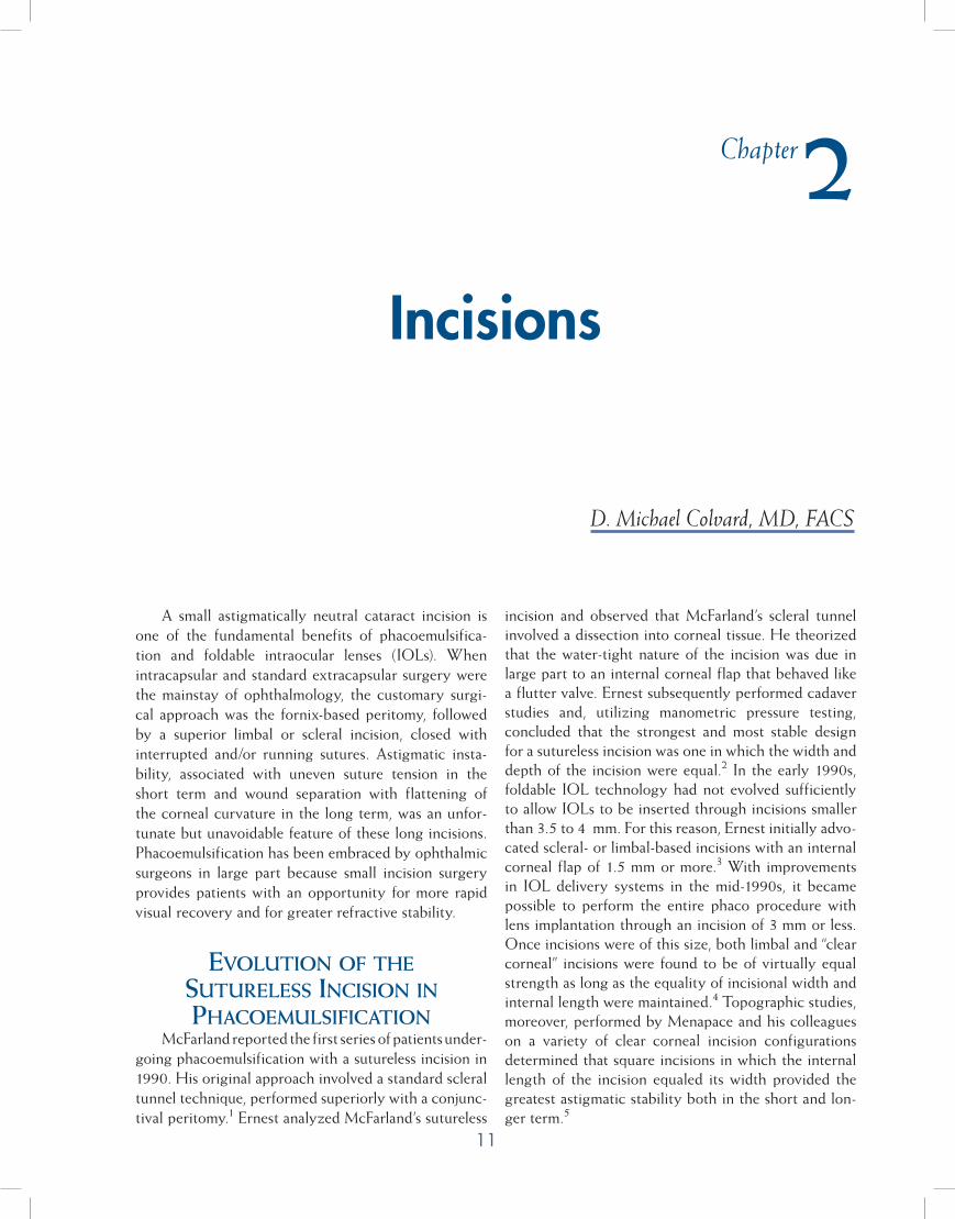
Step 1. Stabilize the Globe. Stabilize the globe using a ring holder placed at the limbus (Figure 2-1).
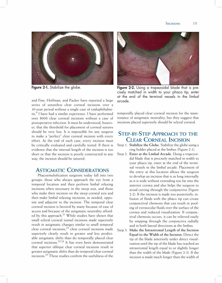
Step 2. Enter at the Limbal Arcade. Using a trapezoi-dal blade that is precisely matched in width to your phaco tip, enter at the end of the termi-nal vessels in the limbal arcade. Placement of the entry at this location allows the surgeon to develop an incision that is as long internally as it is wide without extending too far into the anterior cornea and also helps the surgeon to avoid cutting through the conjunctiva (Figure 2-2). If the incision is made too posteriorly, in-fusion of fluids with the phaco tip can create conjunctival chemosis that can result in pool-ing of extraocular fluids over the surface of the cornea and reduced visualization. If conjunc-tival chemosis occurs, it can be relieved easily by snipping through the conjunctiva radially and in both lateral directions at the limbus.
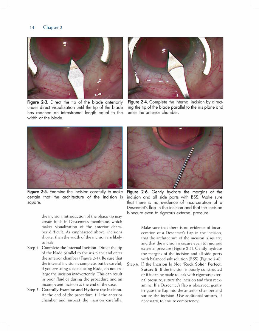
Step 3. Make the Intrastromal Length of the Incision Equal to the Width of the Incision. Direct the tip of the blade anteriorly under direct visual-ization until the tip of the blade has reached an intrastromal length equal to or slightly longer than the width of the blade (Figure 2-3). If the incision is made much longer than the width of
Figure 2-2. Usinga trapezoidalblade that ispre-cisely matched in width to your phaco tip, enterat the end of the terminal vessels in the limbalarcade.
Figure 2-1. Stabilizetheglobe.
14 Chapter 2
the incision, introduction of the phaco tip may create folds in Descemet’s membrane, which makes visualization of the anterior cham-ber difficult. As emphasized above, incisions shorter than the width of the incision are likely to leak.
Step 4. Complete the Internal Incision. Direct the tip of the blade parallel to the iris plane and enter the anterior chamber (Figure 2-4). Be sure that the internal incision is complete, but be careful; if you are using a side cutting blade, do not en-large the incision inadvertently. This can result in poor fluidics during the procedure and an incompetent incision at the end of the case.
Step 5. Carefully Examine and Hydrate the Incision. At the end of the procedure, fill the anterior chamber and inspect the incision carefully.
Make sure that there is no evidence of incar-ceration of a Descemet’s flap in the incision, that the architecture of the incision is square, and that the incision is secure even to rigorous external pressure (Figure 2-5). Gently hydrate the margins of the incision and all side ports with balanced salt solution (BSS) (Figure 2-6).
Step 6. If the Incision Is Not “Rock Solid” Perfect, Suture It. If the incision is poorly constructed or if it can be made to leak with rigorous exter-nal pressure, suture the incision and then reex-amine. If a Descemet’s flap is observed, gently irrigate the flap into the anterior chamber and suture the incision. Use additional sutures, if necessary, to ensure competency.
Figure 2-3. Direct the tip of the blade anteriorlyunderdirectvisualizationuntilthetipofthebladehas reached an intrastromal length equal to thewidthoftheblade.
Figure 2-5. Examinetheincisioncarefullytomakecertain that the architecture of the incision issquare.
Figure 2-4. Completetheinternalincisionbydirect-ingthetipofthebladeparalleltotheirisplaneandentertheanteriorchamber.
Figure 2-6. Gently hydrate the margins of theincision and all side ports with BSS. Make surethat there is no evidence of incarceration of aDescemet’sflapintheincisionandthattheincisionissecureeventorigorousexternalpressure.

Incisions 15
StEP-by-StEP aPProach to thE SclEral cornEal inciSion
Step 1. Perform a Peritomy. Create a fornix-based pe-ritomy, removing all Tenon’s fibers for better hemostasis. Cauterize lightly. Excessive cau-terization can result in scleral shrinkage, which can lead to increased postoperative astigmatic changes and poor approximation of the mar-gins of the external incision (Figure 2-7).
Step 2. Create a Scleral Groove and Scleral Tunnel. Make a scleral groove 1 to 2 mm posterior to the limbus at a depth of approximately 250 microns (Figure 2-8). The width of the scler-al groove should be equal to or only slightly wider than the width of the keratome, which will be used to make the internal entry into
the anterior chamber. Using a “crescent blade,” create a scleral tunnel by dissecting into clear cornea at least 1.5 mm anterior to the limbus (Figure 2-9). Care must be taken not to make the scleral groove and tunnel dissection signif-icantly wider than the keratome used to enter the anterior chamber. This may lead to dif-ficulties with chamber maintenance as it may result in a widening of the internal incision and excessive outflow of irrigating fluids during phacoemulsification.
Step 3. Complete the Internal Incision. Using a kera-tome that is precisely matched to the width of your phaco tip, direct the blade parallel to the iris plane and enter the anterior chamber at the end of the scleral tunnel (Figure 2-10). The use of a keratome that is too narrow for the phaco-emulsification instrument may lead to restric-tion of flow through the irrigation sleeve, over-heating of the phaco tip, and thermal injury to the incision. The use of a keratome that is too large results in excessive outflow around the irrigation sleeve and difficulties with anterior chamber maintenance during the procedure.
Step 4. Examine and Hydrate the Incision. If the Inci-sion Is Not Perfect, Suture It. At the end of the procedure, examine the incision carefully. The incision should be square or nearly square with an internal corneal incision of at least 1.5 mm. If the incision appears well constructed,gently hydrate the margins of the incisionand all side ports with BSS and fill the ante-rior chamber (Figure 2-11). If a Descemet’s flapis observed, gently irrigate the flap into the
Figure 2-8. Make a corneal groove 1 to 2 mmposteriortothelimbusatadepthofapproximately250microns.
Figure 2-7. Createafornix-basedperitomy,remov-ingallTenon’sfibersforbetterhemostasis.Cauterizelightlytoavoidscleralshrinkage.
Figure 2-9. Using a “crescent blade,” create ascleral tunnel by dissecting into clear cornea atleast1.5mmanteriortothelimbus.
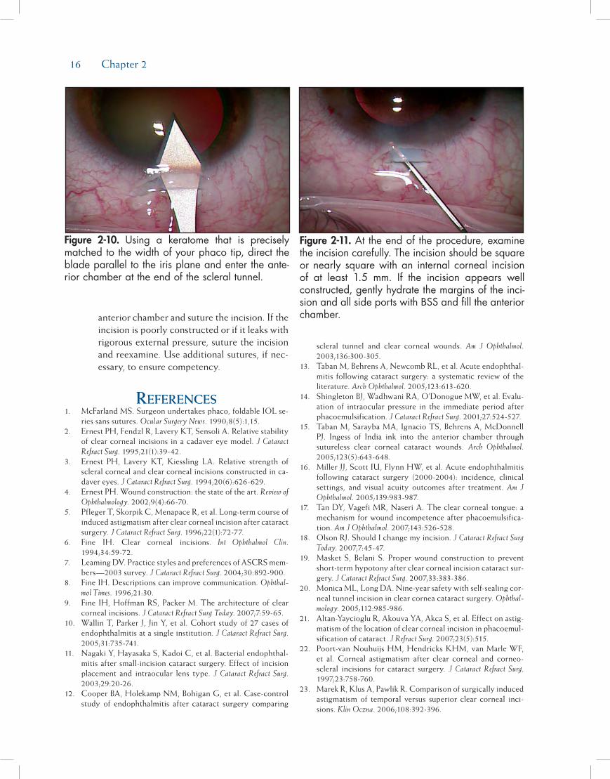
16 Chapter 2
anterior chamber and suture the incision. If the incision is poorly constructed or if it leaks with rigorous external pressure, suture the incision and reexamine. Use additional sutures, if nec-essary, to ensure competency.
rEfErEncES1. McFarland MS. Surgeon undertakes phaco, foldable IOL se-
ries sans sutures. Ocular Surgery News. 1990;8(5):1,15.2. Ernest PH, Fendzl R, Lavery KT, Sensoli A. Relative stability
of clear corneal incisions in a cadaver eye model. J Cataract Refract Surg. 1995;21(1):39-42.
3. Ernest PH, Lavery KT, Kiessling LA. Relative strength of scleral corneal and clear corneal incisions constructed in ca-daver eyes. J Cataract Refract Surg. 1994;20(6):626-629.
4. Ernest PH. Wound construction: the state of the art. Review of Ophthalmology. 2002;9(4):66-70.
5. Pfleger T, Skorpik C, Menapace R, et al. Long-term course of induced astigmatism after clear corneal incision after cataract surgery. J Cataract Refract Surg. 1996;22(1):72-77.
6. Fine IH. Clear corneal incisions. Int Ophthalmol Clin. 1994;34:59-72.
7. Leaming DV. Practice styles and preferences of ASCRS mem-bers—2003 survey. J Cataract Refract Surg. 2004;30:892-900.
8. Fine IH. Descriptions can improve communication. Ophthal-mol Times. 1996;21:30.
9. Fine IH, Hoffman RS, Packer M. The architecture of clear corneal incisions. J Cataract Refract Surg Today. 2007;7:59-65.
10. Wallin T, Parker J, Jin Y, et al. Cohort study of 27 cases of endophthalmitis at a single institution. J Cataract Refract Surg. 2005;31:735-741.
11. Nagaki Y, Hayasaka S, Kadoi C, et al. Bacterial endophthal-mitis after small-incision cataract surgery. Effect of incision placement and intraocular lens type. J Cataract Refract Surg. 2003;29:20-26.
12. Cooper BA, Holekamp NM, Bohigan G, et al. Case-control study of endophthalmitis after cataract surgery comparing
scleral tunnel and clear corneal wounds. Am J Ophthalmol. 2003;136:300-305.
13. Taban M, Behrens A, Newcomb RL, et al. Acute endophthal-mitis following cataract surgery: a systematic review of the literature. Arch Ophthalmol. 2005;123:613-620.
14. Shingleton BJ, Wadhwani RA, O’Donogue MW, et al. Evalu-ation of intraocular pressure in the immediate period after phacoemulsification. J Cataract Refract Surg. 2001;27:524-527.
15. Taban M, Sarayba MA, Ignacio TS, Behrens A, McDonnell PJ. Ingess of India ink into the anterior chamber through sutureless clear corneal cataract wounds. Arch Ophthalmol. 2005;123(5):643-648.
16. Miller JJ, Scott IU, Flynn HW, et al. Acute endophthalmitis following cataract surgery (2000-2004): incidence, clinical settings, and visual acuity outcomes after treatment. Am J Ophthalmol. 2005;139:983-987.
17. Tan DY, Vagefi MR, Naseri A. The clear corneal tongue: a mechanism for wound incompetence after phacoemulsifica-tion. Am J Ophthalmol. 2007;143:526-528.
18. Olson RJ. Should I change my incision. J Cataract Refract Surg Today. 2007;7:45-47.
19. Masket S, Belani S. Proper wound construction to prevent short-term hypotony after clear corneal incision cataract sur-gery. J Cataract Refract Surg. 2007;33:383-386.
20. Monica ML, Long DA. Nine-year safety with self-sealing cor-neal tunnel incision in clear cornea cataract surgery. Ophthal-mology. 2005;112:985-986.
21. Altan-Yaycioglu R, Akouva YA, Akca S, et al. Effect on astig-matism of the location of clear corneal incision in phacoemul-sification of cataract. J Refract Surg. 2007;23(5):515.
22. Poort-van Nouhuijs HM, Hendricks KHM, van Marle WF, et al. Corneal astigmatism after clear corneal and corneo-scleral incisions for cataract surgery. J Cataract Refract Surg. 1997;23:758-760.
23. Marek R, Klus A, Pawlik R. Comparison of surgically induced astigmatism of temporal versus superior clear corneal inci-sions. Klin Oczna. 2006;108:392-396.
Figure 2-11. Attheendoftheprocedure,examinetheincisioncarefully.Theincisionshouldbesquareornearly squarewithan internalcorneal incisionof at least 1.5 mm. If the incision appears wellconstructed,gentlyhydratethemarginsoftheinci-sionandallsideportswithBSSandfilltheanteriorchamber.
Figure 2-10. Using a keratome that is preciselymatchedtothewidthofyourphacotip,directthebladeparalleltotheirisplaneandentertheante-riorchamberattheendofthescleraltunnel.

Incisions 17
24. Simisek S, Yasar T, Demirok A, et al. Effect of superior andtemporal clear corneal incisions on astigmatism after suture-less phacoemulsification. J Cataract Refract Surg. 1998;24:515-518.
25. Rainer G, Menapace R, Vass C, et al. Corneal shape changesafter temporal and superolateral 3.0 mm clear corneal inci-sions. J Cataract Refract Surg. 1999;25:1121-1126.

19
Cataract extraction by the extracapsular method requires an opening of the anterior capsule. Before Charles Kelman’s development of phacoemulsification, when standard extracapsular surgery was performed routinely, the capsule was opened with a multi-jaw forceps, pinching it until it tore from both sides.1 Typically, an Aruga forceps was used (Figure 3-1). As large an opening as possible was ideal because the lens nucleus was then expressed from the capsular bag into the chamber and out of the incision. Kelman described a more controlled opening using a blunt cystotome, creating a triangular tear (the so-called “Christmas tree” tear) starting from the 6 o’clock position of the pupil (Figure 3-2). The torn capsular tag was pulled out of the superior incision and cut off, creating a triangular opening (Figure 3-3). The triangular open-ing technique was then modified with additional tears (Figure 3-4), and eventually the “can opener” technique evolved with multiple tears placed in a circular fashion. This technique helped to reduce the risks of engage-ment of the capsular flaps during phacoemulsification and cortex removal because the multiple small tears resulted in smaller capsular flaps (Figure 3-5). The mechanical stress on the margin of the can opener capsulotomy, caused by sculpting and manipulation of the nucleus, however, sometimes resulted in the
radial extension of one of the small tear notches. These tears then extended to the periphery of the capsule and “zipped” around the equator, resulting in a poste-rior capsular tear. As phacoemulsification techniques progressed from anterior chamber emulsification to in-the-bag disassembly of the nucleus, manipulation within the capsular bag increased and the need to develop a more tear-resistant opening in the anterior capsule became increasingly critical. The development of a continuous circular capsular tear technique, which came to be called continuous curvilinear capsulor-rhexis (CCC), greatly increased the safety of cataract surgery.2 Highly resistant to the development of radial tears, CCC greatly reduced the risk of intraoperative posterior capsular tears3 and paved the way for the development of a variety of lens disassembly tech-niques, which also increased the safety of phacoemul-sification. CCC also increased the ability of surgeons to place both loops of an intraocular lens (IOL) within the capsular bag more reliably and, because the circular capsular opening helped to ensure symmetrical capsu-lar contraction forces, the technique helped to obtain and maintain better centration of the IOL.
After its introduction, CCC gradually became adopted by ophthalmic surgeons because of its clear advantages. The technique, however, is not as easy to
Chapter
Capsulorrhexis
Howard V. Gimbel, MD, MPH, FACS, FRCSC
3
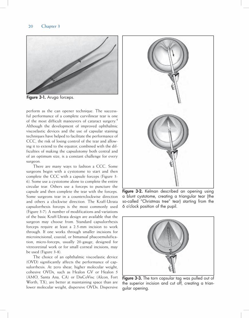
20 Chapter 3
perform as the can opener technique. The success-ful performance of a complete curvilinear tear is one of the most difficult maneuvers of cataract surgery.4 Although the development of improved ophthalmic viscoelastic devices and the use of capsular staining techniques have helped to facilitate the performance of CCC, the risk of losing control of the tear and allow-ing it to extend to the equator, combined with the dif-ficulties of making the capsulotomy both central and of an optimum size, is a constant challenge for every surgeon.
There are many ways to fashion a CCC. Some surgeons begin with a cystotome to start and then complete the CCC with a capsule forceps (Figure 3-6). Some use a cystotome alone to complete the entire circular tear. Others use a forceps to puncture the capsule and then complete the tear with the forceps. Some surgeons tear in a counterclockwise direction and others a clockwise direction. The Kraff-Utrata capsulorrhexis forceps is the most commonly used (Figure 3-7). A number of modifications and variations of the basic Kraff-Utrata design are available that the surgeon may choose from. Standard capsulorrhexis forceps require at least a 2.5-mm incision to work through. If one works through smaller incisions for microincisional, coaxial, or bimanual phacoemulsifica-tion, micro-forceps, usually 20-gauge, designed for vitreoretinal work or for small corneal incisions, may be used (Figure 3-8).
The choice of an ophthalmic viscoelastic device (OVD) significantly affects the performance of cap-sulorrhexis. At zero shear, higher molecular weight, cohesive OVDs, such as Healon GV or Healon 5 (AMO, Santa Ana, CA) or DisCoVisc (Alcon, Fort Worth, TX), are better at maintaining space than are lower molecular weight, dispersive OVDs. Dispersive
Figure 3-1. Aruga forceps.
Figure 3-3. The torn capsular tag was pulled out of the superior incision and cut off, creating a trian-gular opening.
Figure 3-2. Kelman described an opening using a blunt cystotome, creating a triangular tear (the so-called “Christmas tree” tear) starting from the 6 o’clock position of the pupil.

Capsulorrhexis 21
OVDs, such as Healon D (AMO) and Viscoat (Alcon), offer more coating and provide more protection for the corneal endothelium during phacoemulsification, but when there is no fluid movement in the eye (zero shear), these OVDs are more runny and less retentive than are the higher molecular weight OVDs. A cohesive, highly retentive OVD provides the most flattening of the anterior capsule and the most stable anterior chamber during capsulorrhexis. It is more difficult, however, to pull the torn flap of tissue through a highly cohesive OVD. Using these viscoelastics, care is required when tearing the capsule with the forceps or cystotome. One must be careful not to allow the tear to turn centrally, as this tends to make an opening smaller than desired. With these highly retentive viscoelastics, however, it is easier to prevent the tear from radializing. This allows for the performance of a safe capsule opening in more challenging cases such as eyes with very shallow chambers, loose or missing zonules, children’s cata-racts, and in lenses that are mature and intumescent.
Figure 3-4. Kelman’s trian-gular opening technique progressed to a few tears with small flaps.
Figure 3-5. The can opener capsulotomy.

22 Chapter 3
These higher molecular weight OVDs are particularly helpful when opening the capsules of young people and children where the lens material is soft and the capsule is very elastic. With a cohesive, high molecular weight viscoelastic, one is able to flatten the anterior capsule and equalize the pressure on each side of the capsule. A flat capsule rather than a dome allows for a more controlled CCC opening. In addition, these high molecular weight viscoelastic materials are helpful with intumescent cataracts. Surgeons have long known that emptying of the capsular bag of soft cloudy liq-uid material through a small opening prior to CCC makes the procedure more controllable. Before stains such as trypan blue (Vision Blue, Dutch Ophthalmic, Exeter, NH) were available, surgeons performed this aspiration technique when the lens material was mostly liquid but completely white and under a lot of pressure. This approach should be kept is mind for special situ-ations such as a rapidly developing traumatic cataract
and for fibrotic anterior capsules that require cutting with micro-scissors (Figure 3-9). The fibrosis may be better visualized after soft cortical material has been aspirated, a red reflex obtained, and more viscoelastic has been added.
Step-by-StepApproAchtocontinuouScurvilineAr
cApSulorrhexiSStep 1. Select the Optimal OVD(s) for the Specific
Case. As noted previously, cohesive high mo-lecular weight OVDs provide optimal flatten-ing of the anterior lens capsule and are better at chamber maintenance than are dispersive, low molecular weight OVDs. In cases of extremely dense cataracts, or if an endothelial dystrophy
Figure 3-6. CCC may be fashioned using a forceps, cystotome, or a combina-tion of both.
Figure 3-7. Kraff-Utrata capsulorrhexis forceps.
Figure 3-8. Microincisional forceps. Figure 3-9. Fibrotic anterior capsule opened with angled micro-scissors.

Capsulorrhexis 23
exists, a dispersive OVD may be used to coat the endothelium for increased protection, and then a more retentive, cohesive OVD may be used to fill the anterior chamber for capsulor-rhexis.
Step 2. Begin the Tear Centrally and Create a Cap-sular Flap. Once the anterior chamber is filled with viscoelastic, the capsule is punctured cen-trally with a sharp bent cystotome needle or a sharp capsule forceps and the tear guided away from the center in a direction that will enable the surgeon to easily grasp the develop-ing flap with the forceps. This may be just a vertical tear away from or toward the incision or a curving tear that is directed radially to the desired diameter of the CCC. The tear is then continued in a circumferential direction to cre-ate a flap edge. Using the forceps or additional OVD under the flap, elevate the flap vertically into the anterior chamber to make it easier to grasp with forceps
Step 3. Grasp the Flap and Begin the Curvilinear Tear. Once the flap is elevated, grasp the flap with the forceps and continue the circular, or at least curvilinear, tear until it is complete. When performing capsulorrhexis, the flap must be regrasped or reengaged a few times to control the direction of the tear. The more difficult the direction of the curvilinear tear is to control, the more frequently the flap must be released and regrasped. Each time the flap is released, be sure to elevate the flap edge in order to make the flap easier to grasp again.
Step 4. Optimize Control of the Tear. Control of the direction of the tear is optimized when the flap is regrasped near the point of tearing. The flap is then folded on itself, and a shearing tech-nique is used to better direct the tear. Tear-ing the capsule by simply pulling the capsule centrally gives the surgeon less control of the direction of the tear. Folding the capsule over itself, moreover, causes less stress on the zo-nular ligament and prevents the capsule from shifting from a tug on the zonules while the tear is fashioned. Such a shift can result in an eccentric opening in the capsule or one that is larger than desired. In routine cases this shear-ing technique can be combined with direct tearing for some portions of the circle. When direct tearing is used, one has to be aware of vector forces and watch the point of tearing
rather than the point of the forceps. The vec-tor force required to direct the tear appropri-ately varies as the tear progresses around the circle. The capsule is more elastic and less “brittle” in young eyes, and the direction of the force of the forceps is usually quite radial centripetally or toward the center of the pupil. It is sometimes necessary to pull in a direction 90 degrees from the direction of the tear. In these eyes it is important to release frequently to verify the diameter of the tear as the zonules and the capsule are so elastic. It is also very important to regrasp every 1 or 2 clock hours to keep control of the direction and diameter of the tear.
Additional Points of ImportanceThe ideal diameter of the capsular opening is now
widely believed to be about 5 mm. This allows the CCC rim to cover the edge of the 6-mm IOL optic. Nishi and Nishi have shown that there is less fibrous opacification of the posterior capsule postoperatively if the margin of the anterior capsule rim does not touch the posterior capsule.5 This also makes it important to make the capsular opening as central as possible and not too oval or outside of the diameter of the optic in any meridian.
In 2005, Tassignon et al of Belgium introduced a newly designed ring caliper to facilitate the sizing and centration of the CCC along the alignment of the first and third Purkinje reflexes as observed under the microscope.6 Most surgeons do not have this device available and simply make their best effort to center the CCC and to make it of an optimal size. Some surgeons place a ring mark on the cornea with a zone marker to assist in sizing and placement of the CCC.2
If the CCC ends up too small or is eccentric, a technique that I have described as “two-staged CCC” may be considered to enlarge it or make it more round. This technique may also be used to start a tear going in the opposite direction from one that has radialized or to convert a small can opener opening to a CCC (Figure 3-10). To start a new tear in the edge of an existing opening, a scissor is used to make a very short tangential cut. The new beginning flap is then grasped with forceps and the new tear is continued around the circle of desired diameter (Figure 3-11). If this new start needs to be in the subincisional area, one may have to make another capsule puncture with a sharp needle or cystotome to start a new tear. Angled vitrectomy scissors may be used as well for unusual situations.

24 Chapter 3
Careful placement of a cohesive viscoelastic under and over the capsule is necessary to safely start the new tear.
A capsule with a fibrotic zone or an entirely fibrot-ic anterior capsule presents a challenge. If the fibrosis is just a band in a quadrant easy to reach with a scis-sors, one may cut through the band with the scissors. An elegant technique is to use a Fugo blade instrument (Medisurg Research and Management, Norristown, PA) which cuts with a plasma field around a fine fila-ment.7 This device cuts with ease through fibrosis as well as normal capsule and can be used to enlarge CCCs or manage uncontrolled capsule tears. The device is also useful in the management of traumatic openings in the anterior capsule that cannot be safely handled with scissors and forceps.
Posterior continuous curvilinear capsulorrhexis (PCCC) may also be performed.8 The same principles apply when creating an opening in the posterior cap-sule as in the anterior capsule. When opening the posterior capsule, one may decide to not prevent for-ward movement of the vitreous because a vitrectomy is planned and thus take no precautions to protect it. If, however, one wishes to avoid a vitrectomy and protect the vitreous, it is important to start the PCCC with a hooking snag rather than a cutting puncture.
A small snag may be created using the barbed end of a disposable 27-gauge hypodermic needle. This small barb may be made by pressing the tip of the needle on the handle of a needle driver or forceps until a very small, right angle bend is made in the tip. Once the opening is made, the vitreous is pushed back with additional viscoelastic through the opening. The tear-ing is then continued and additional viscoelastic is added intermittently to keep viscoelastic under the capsule where the flap of capsule is being regrasped. The size of the PCCC should be at least 3 to 4 mm for a good-sized opening that will always be clear of secondary cataract, except in children where cells use the intact vitreous face as a scaffold and occlude the visual axis; in this case, when the technique of PCCC optic capture is planned, the opening should be about 4.5 mm (Figure 3-12).9 Openings larger than this may not capture the haptic optic junctions tightly enough to prevent lens epithelial cells from migrating behind the IOL to opacify the visual axis by depositing new lens material on the intact vitreous face (Figure 3-13). If the opening is smaller than 4.5 mm, and thus too small for optic capture, the two-stage technique may be used to enlarge it just as with the anterior capsule.
The PCCC may be used for access to the vitreous cavity for a number of indications such as the removal
Figure 3-10. Conversion of can opener capsu-lotomy using two-staged CCC technique.
Figure 3-11. An addition-al ribbon of capsule is removed using forceps and continued around for desired diameter.
Figure 3-12. PCCC and PCCC with optic capture.

Capsulorrhexis 25
of silicone oil, reduction of asteroid hyalosis, for ante-rior vitrectomy and antibiotic injection in cases of presumed postoperative endophthalmitis, and to pre-vent secondary cataract by preemptively opening the posterior capsule. Capsular dyes may be helpful when doing PCCC, especially when there is a poor fundus reflex, as with asteroid hyalosis and endophthalmitis. Indications for PCCC in order to prevent secondary cataract include severe kyphosis and socioeconomic barriers to Nd:YAG laser capsulotomy.
Openings in the posterior capsule may be made many years after primary surgery. This may be indi-cated when IOL removal and replacement or IOL repositioning is needed and membrane optic capture is planned to fix the IOL to the capsular membrane. If there is no fibrosis in a 4- to 5-mm zone of the capsular membrane, the opening may be made with the tearing techniques described above. If there is fibrosis pres-ent or the single posterior layer of capsule is not large enough for a desired 4- to 5-mm opening, the Fugo blade or scissors would have to be used with increased risk of disturbing the vitreous and of extension of the tear by the force required to get optic capture.
In secondary surgery for improved fixation, repo-sitioning, or removal and replacement of an IOL,
another fixation technique to utilize for fixation of the IOL to the capsule is capsular membrane suture fixation.10 In this technique the haptics of the IOL are sutured to the fibrotic elements of the capsular mem-brane to fix the IOL to the capsular membrane rather than leave it loose in the sulcus to erode iris pigment, erode iris vessels, and potentially become eccentric (Figure 3-14).
referenceS1. Kelman CD. Phaco-emulsification and aspiration. A new
technique of cataract removal. A preliminary report. Am J Ophthalmol. 1967;64(1):23-35.
2. Bond W, Bakewell BK, Agarwal A, Spalton D. Sizing and centering the capsulorrhexis. J Cataract Refract Surg Today. 2007;7(4):27-32.
3. Gimbel HV. Divide and conquer nucleofractis phacoemul-sification: development and variations. J Cataract Refract Surg. 1991;17(3):281-291.
4. Gimbel HV, Neuhann T. Development, advantages, and methods of the continuous circular capsulorrhexis technique. J Cataract Refract Surg. 1990;16(1):31-37.
5. Nishi O, Nishi K. Effect of the optic size of a single-piece acrylic intraocular lens on posterior capsule opacification. J Cataract Refract Surg. 2003;29(2):348-353.
6. Tassignon MJ, Rozema JJ, Gobin L. Ring-shaped caliper for better anterior capsulorrhexis sizing and centration. J Cata-
Figure 3-13. PCCC with optic capture prevents the migration of Elschnig pearls and maintains a clear visual axis.
Figure 3-14. Capsule mem-brane suture technique of fixating a decentered or dislocated IOL.

26 Chapter 3
ract Refract Surg. 2006;32(8):1253-1255.7. Fugo RJ. Fugo blade to enlarge phimotic capsulorrhexis. [Let-
ter] J Cataract Refract Surg. 2006;32(11):1900.8. Gimbel HV. Posterior capsule tears using phaco-emulsifica-
tion. Causes, prevention and management. Eur J Implant Refract Surg. 1990;2(1):63-69.
9. Gimbel HV, DeBroff BM. Intraocular lens optic capture. J Cataract Refract Surg. 2004;30(1):200-206.
10. Gimbel HV, Shah CR, Venkataraman A, Rattray KM. Capsu-lar membrane suture fixation of sulcus IOLs. Clinical & Surgical Ophthalmlolgy. 2008;26(2):42-47.
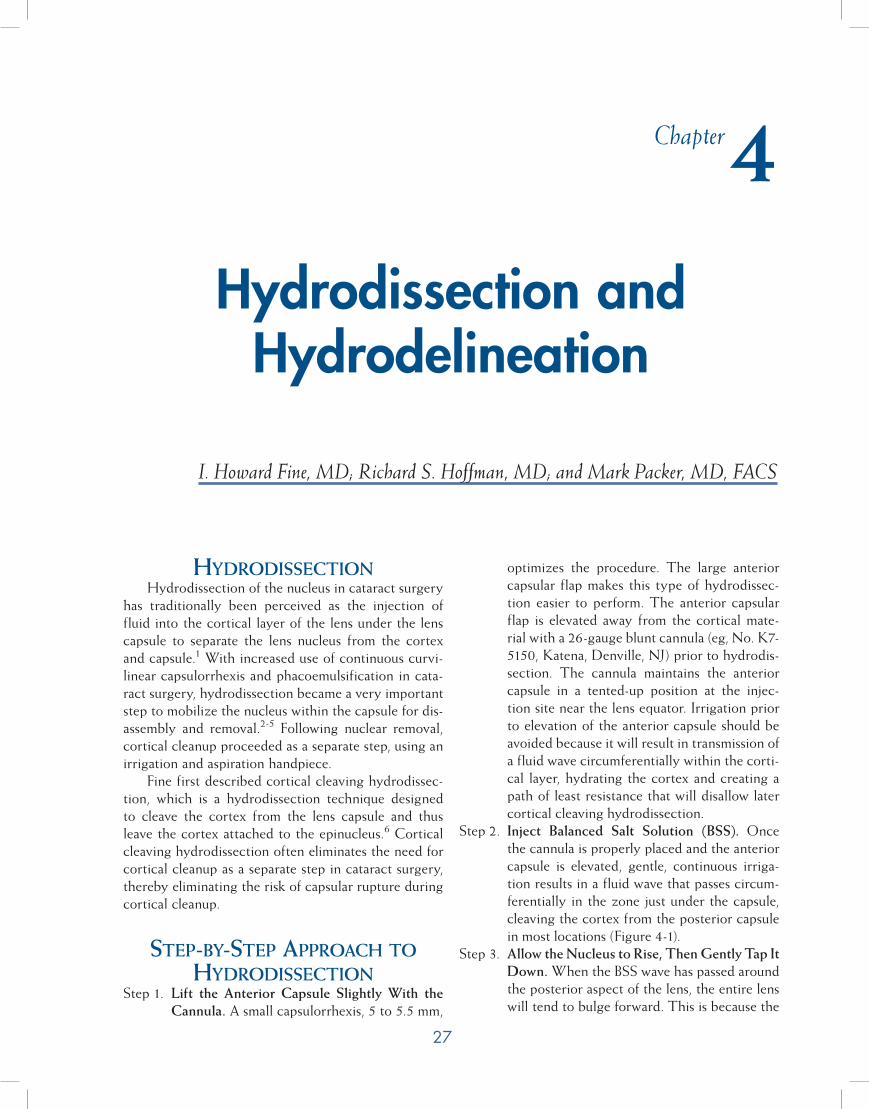
27
HydrodissectionHydrodissection of the nucleus in cataract surgery
has traditionally been perceived as the injection of fluid into the cortical layer of the lens under the lens capsule to separate the lens nucleus from the cortex and capsule.1 With increased use of continuous curvi-linear capsulorrhexis and phacoemulsification in cata-ract surgery, hydrodissection became a very important step to mobilize the nucleus within the capsule for dis-assembly and removal.2-5 Following nuclear removal, cortical cleanup proceeded as a separate step, using an irrigation and aspiration handpiece.
Fine first described cortical cleaving hydrodissec-tion, which is a hydrodissection technique designed to cleave the cortex from the lens capsule and thus leave the cortex attached to the epinucleus.6 Cortical cleaving hydrodissection often eliminates the need for cortical cleanup as a separate step in cataract surgery, thereby eliminating the risk of capsular rupture during cortical cleanup.
step-by-step ApproAcH to Hydrodissection
Step 1. Lift the Anterior Capsule Slightly With the Cannula. A small capsulorrhexis, 5 to 5.5 mm,
optimizes the procedure. The large anterior capsular flap makes this type of hydrodissec-tion easier to perform. The anterior capsular flap is elevated away from the cortical mate-rial with a 26-gauge blunt cannula (eg, No. K7-5150, Katena, Denville, NJ) prior to hydrodis-section. The cannula maintains the anterior capsule in a tented-up position at the injec-tion site near the lens equator. Irrigation prior to elevation of the anterior capsule should be avoided because it will result in transmission of a fluid wave circumferentially within the corti-cal layer, hydrating the cortex and creating a path of least resistance that will disallow later cortical cleaving hydrodissection.
Step 2. Inject Balanced Salt Solution (BSS). Once the cannula is properly placed and the anterior capsule is elevated, gentle, continuous irriga-tion results in a fluid wave that passes circum-ferentially in the zone just under the capsule, cleaving the cortex from the posterior capsule in most locations (Figure 4-1).
Step 3. Allow the Nucleus to Rise, Then Gently Tap It Down. When the BSS wave has passed around the posterior aspect of the lens, the entire lens will tend to bulge forward. This is because the
Chapter
Hydrodissection and Hydrodelineation
I. Howard Fine, MD; Richard S. Hoffman, MD; and Mark Packer, MD, FACS
4

28 Chapter 4
fluid is trapped by the firm equatorial cortical-capsular connections. The procedure creates, in effect, a temporary intraoperative version of capsular block syndrome as seen by enlarge-ment of the diameter of the capsulorrhexis (Figure 4-2). At this point, if fluid injection is continued, a portion of the lens prolapses through the capsulorrhexis. However, if prior to prolapse the capsule is decompressed by de-pressing the central portion of the lens with the side of the cannula in a way that forces fluid to come around the lens equator from behind, the cortical-capsular connections in the capsu-lar fornix and under the anterior capsular flap are cleaved. The cleavage of cortex from the capsule equatorially and anteriorly allows fluid to exit from the capsular bag via the capsulor-rhexis, which constricts to its original size (Fig-ure 4-3), and mobilizes the lens in such a way that it can spin freely within the capsular bag.
Step 4. Repeat Injection of BSS at the Opposite Dis-tal Quadrant. Repeating the hydrodissection and capsular decompression at the opposite distal quadrant may be helpful. Adequate hy-drodissection at this point is demonstrable by the ease with which the nuclear-cortical com-plex can be rotated by the cannula.
HydrodelineAtionHydrodelineation is a term first used by Anis to
describe the act of separating an outer epinuclear shell
or multiple shells from the central compact mass of inner nuclear material, the endonucleus, by the forceful irrigation of fluid (BSS) into the mass of the nucleus.7
step-by-step ApproAcH to HydrodelineAtion
Step 1. Use the Cannula to Locate the Endonucleus. A 26-gauge cannula is placed in the nucleus, off center to either side, and directed at an an-gle downward and forward toward the central plane of the nucleus. When the nucleus starts to move, the endonucleus has been reached. It is not penetrated by the cannula. At this point, the cannula is directed tangentially to the en-donucleus, and a to-and-fro movement of the cannula is used to create a tract within the nucleus.
Figure 4-1. Anterior capsule is tented up by the cannula, fluid wave is moving posteriorly, and cap-sulorrhexis is enlarged (arrows=fluid wave).
Figure 4-2. Capsulorrhexis is enlarged by the poste-rior located fluid pushing the lens forward.
Figure 4-3. Return of the capsulorrhexis to its previ-ous size after decompression of the capsule.

Hydrodissection and Hydrodelineation 29
Step 2. Inject BSS to Create a Cleave Plane. The can-nula is backed out of the tract approximately halfway, and a gentle but steady pressure on the syringe allows fluid to enter the distal tract without resistance. Driven by the hydraulic force of the syringe, the fluid will find the path of least resistance, which is the junction be-tween the endonucleus and the epinucleus, and flow circumferentially in this contour. Most frequently, a circumferential golden ring will be seen outlining the cleavage between the epinucleus and the endonucleus (Figure 4-4). Sometimes the ring will appear as a dark circle rather than a golden ring.
Occasionally, an arc will result and surround approximately one quadrant of the endonu-cleus. In this instance, creating another tract the same depth as the first but ending at one end of the arc, and injecting into the middle of the second tract, will extend that arc (usu-ally another full quadrant). This procedure can be repeated until a golden or dark ring verifies circumferential division of the nucleus.
AdditionAl tipsFor very soft nuclei, the placement of the cannula
allows creation of an epinuclear shell of any thickness. The cannula may pass through the entire nucleus if it is soft enough, so the placement of the tract and the location of the injection allow an epinuclear shell to be
fashioned as desired. In very firm nuclei, one appears to be injecting into the cortex on the anterior surface of the nucleus, and the golden ring will not be seen. However, a thin, hard epinuclear shell is achieved even in the most brunescent nuclei. That shell will offer the same protection as a thicker epinucleus in a softer cataract.
Hydrodelineation circumferentially divides the nucleus and has many advantages. Circumferential division reduces the volume of the central portion of nucleus removed by phacoemulsification by up to 50%. This allows less deep and less peripheral groov-ing and smaller, more easily mobilized quadrants after cracking or chopping. The epinucleus acts as a protec-tive cushion within which all of the chopping, crack-ing, and phacoemulsification forces can be confined. In addition, the epinucleus keeps the bag on stretch throughout the procedure, making it unlikely that a knuckle of capsule will come forward, occlude the phaco tip, and rupture.
Cortical cleanup is dramatically facilitated by cortical cleaving hydrodissection. After evacuation of all endonuclear material, the epinuclear rim is trimmed in each of the three quadrants, mobilizing cortex as well in the following way. As each quadrant of the epinuclear rim is rotated to the distal position in the capsule and trimmed, the cortex in the adjacent capsular fornix flows over the floor of the epinucleus and into the phaco tip (Figure 4-5). Then the floor is pushed back to keep the bag on stretch until three of the four quadrants of the epinuclear rim and forniceal cortex have been evacuated. It is important not to allow the epinucleus to flip too early, thus avoiding a large amount of residual cortex remaining after evacu-ation of the epinucleus.
The epinuclear rim of the fourth quadrant is then used as a handle to flip the epinucleus. As the remain-ing portion of the epinuclear floor and rim is evacu-ated from the eye, 70% of the time the entire cortex is evacuated with it.8 Downsized phaco tips with their increased resistance to flow are less capable of mobi-lizing the cortex because of the decreased minisurge accompanying the clearance of the tip when going from foot position 2 to foot position 3 in trimming of the epinucleus.
After the intraocular lens (IOL) is inserted, these strands and any residual viscoelastic material are removed using the irrigation-aspiration tip, leaving a clean capsular bag.
If there is cortex still remaining following removal of all the nucleus and epinucleus (Figure 4-6), there are
Figure 4-4. The golden ring outlining the cleaving between the epinucleus and the endonucleus is clearly visible.
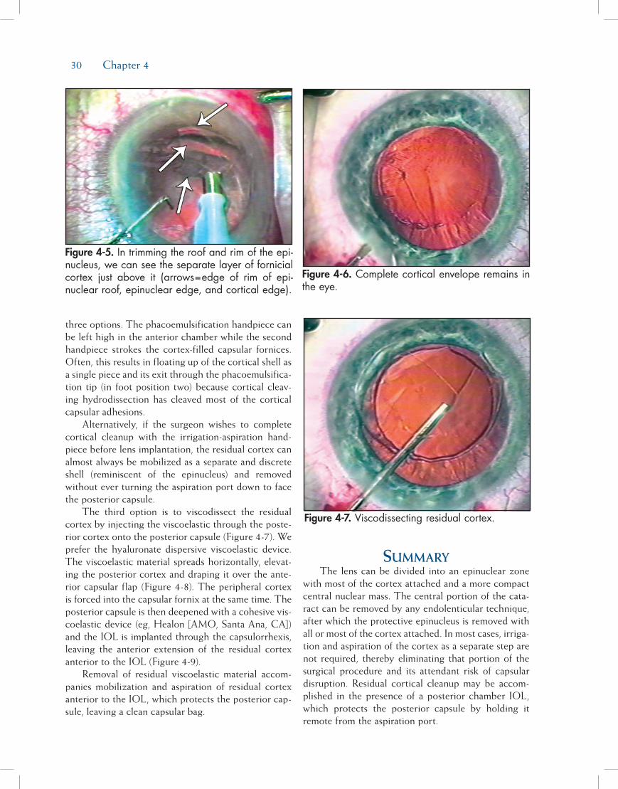
30 Chapter 4
three options. The phacoemulsification handpiece can be left high in the anterior chamber while the second handpiece strokes the cortex-filled capsular fornices. Often, this results in floating up of the cortical shell as a single piece and its exit through the phacoemulsifica-tion tip (in foot position two) because cortical cleav-ing hydrodissection has cleaved most of the cortical capsular adhesions.
Alternatively, if the surgeon wishes to complete cortical cleanup with the irrigation-aspiration hand-piece before lens implantation, the residual cortex can almost always be mobilized as a separate and discrete shell (reminiscent of the epinucleus) and removed without ever turning the aspiration port down to face the posterior capsule.
The third option is to viscodissect the residual cortex by injecting the viscoelastic through the poste-rior cortex onto the posterior capsule (Figure 4-7). We prefer the hyaluronate dispersive viscoelastic device. The viscoelastic material spreads horizontally, elevat-ing the posterior cortex and draping it over the ante-rior capsular flap (Figure 4-8). The peripheral cortex is forced into the capsular fornix at the same time. The posterior capsule is then deepened with a cohesive vis-coelastic device (eg, Healon [AMO, Santa Ana, CA]) and the IOL is implanted through the capsulorrhexis, leaving the anterior extension of the residual cortex anterior to the IOL (Figure 4-9).
Removal of residual viscoelastic material accom-panies mobilization and aspiration of residual cortex anterior to the IOL, which protects the posterior cap-sule, leaving a clean capsular bag.
summAryThe lens can be divided into an epinuclear zone
with most of the cortex attached and a more compact central nuclear mass. The central portion of the cata-ract can be removed by any endolenticular technique, after which the protective epinucleus is removed with all or most of the cortex attached. In most cases, irriga-tion and aspiration of the cortex as a separate step are not required, thereby eliminating that portion of the surgical procedure and its attendant risk of capsular disruption. Residual cortical cleanup may be accom-plished in the presence of a posterior chamber IOL, which protects the posterior capsule by holding it remote from the aspiration port.
Figure 4-5. In trimming the roof and rim of the epi-nucleus, we can see the separate layer of fornicial cortex just above it (arrows=edge of rim of epi-nuclear roof, epinuclear edge, and cortical edge).
Figure 4-7. Viscodissecting residual cortex.
Figure 4-6. Complete cortical envelope remains in the eye.

Hydrodissection and Hydrodelineation 31
references1. Faust KJ. Hydrodissection of soft nuclei. Am Intraocular Implant
Soc J. 1984;10:75-77.2. Davison JA. Bimodal capsular bag phacoemulsification: a se-
rial cutting and suction ultrasonic nuclear dissection tech-nique. J Cataract Refract Surg. 1989;15:272-282.
3. Sheperd JR. In situ fracture. J Cataract Refract Surg. 1990;16:436-440.
4. Gimbel HV. Divide and conquer nucleofractis phacoemul-sification: development and variations. J Cataract Refract Surg.1991;17:281-291.
5. Fine IH. The chip and flip phacoemulsification technique.J Cataract Refract Surg. 1991;17:366-371.
6. Fine IH. Cortical cleaving hydrodissection. J Cataract Refract Surg. 1992;18(5):508-512.
7. Anis A. Understanding hydrodelineation: the term and re-lated procedures. Ocular Surg News. 1991;9:134-137.
8. Fine IH. The choo-choo chop and flip phacoemulsificationtechnique. Operative Techniques in Cataract and Refractive Surgery.1998;1(2):61-65.
Figure 4-8. Posterior cortex fully draped on top of capsule and iris (arrows=edges of posterior cortex are elevated by viscoelastic).
Figure 4-9. Posterior cortex now draped back on top of the plate haptic IOL ready for mobilization.

33
Part A:Disassembling the Nucleus—
An Overview
D. Michael Colvard, MD, FACS
The introduction of the continuous curvilinear cap-sulorrhexis by Howard Gimbel and Thomas Neuhann1 in the early 1990s solved two critically important problems for phacoemulsification surgeons and created a new challenge. The traditional can opener capsuloto-my, used for years by phaco surgeons, was prone to the development of radial tears. These tears often “zipped” around the equator of the lens capsule, extended to the posterior capsule, and were a major source of intra-operative complications. Even when the radial tears remained small and caused no intraoperative problems, asymmetric capsular contractional forces associated an irregular capsular margin frequently lead to intraocular lens (IOL) decentration. Gimbel and Neuhann’s new technique resulted in greater stability of the capsular bag during phacoemulsification and improved centra-tion of IOLs. The problem with capsulorrhexis was that it restricted access to the nucleus. The anterior capsu-lar margin resisted the development of radial tears,
but it also held the nucleus tightly within the capsular bag. The old method of tipping the entire nucleus of a dense cataract into the pupillary plane could no lon-ger be used. The new challenge for surgeons was to devise a method for removing an 8- to 10-mm nucleus through a 4- to 7-mm capsular opening.
Surgeons struggled initially as they attempted to modify their techniques of phacoemulsification to meet the challenge posed by capsulorrhexis. “Endocapsular” techniques of emulsifying the nucleus entirely within the capsular bag were proposed by a number of sur-geons,2-4 but the awkwardness and inherent difficulties and dangers of performing these techniques prevented them from gaining wide acceptance. Gradually, a vari-ety of techniques for cracking or fracturing the nucleus within the capsular bag evolved, and the approach of first disassembling the nucleus and then bringing sec-tions of the nucleus into a “safe zone” for emulsification became the foundation of all phaco techniques used today.
The term divide and conquer was first proposed by Howard Gimbel.5 Dr. Gimbel described a systematic fracturing of the nucleus within the capsular bag using the phaco tip and a surgical spatula.6 John Shepherd modified Gimbel’s approach and developed an elegant technique for divide and conquer that is widely used
Phaco Techniques
D. Michael Colvard, MD, FACS; David F. Chang, MD; Mark Packer, MD, FACS; I. Howard Fine, MD; and Richard S. Hoffman, MD
Chapter5

34 Chapter 5
today. This technique involves the creation of two deep grooves in the nucleus that intersect centrally, followed by the cracking of the nucleus into four separate quadrants.7 Kunihiro Nagahara soon followed with an alternative approach for disassembling the nucleus, using a horizontal chopping technique.8 His innovative concept of using the phaco tip to stabilize the nucleus and then to use a chopping device to cre-ate countertractional forces within the nucleus is the basis of a variety of chopping techniques used today. The horizontal chop involves placement of a chopping device under the anterior margin of the capsulorrhexis and then, after stabilizing the nucleus with the phaco tip, pulling the chopper horizontally toward the center to the nucleus. The vertical chop technique utilizes a sharp chopper that is embedded in the nucleus cen-trally. The chopper is pushed downward as the phaco tip is lifted upward, creating a cleavage plane. As a fissure develops, the crack is completed by separating the chopper and phaco tip in a direction 90 degrees to the axis of the cleavage plane.
Divide and conquer, horizontal chopping, and vertical chopping techniques all have one thing in common: they create cleavage planes that allow the surgeon to disassemble the nucleus into smaller frag-ments. These smaller fragments can then be drawn away from the capsule and into the center of the ante-rior segment where they can be emulsified more safely. The fundamental difference in these techniques is the direction of the forces that create the cleavage planes. With divide and conquer techniques, the forces are radial and centrifugal. With horizontal chop, the forc-es are radial and centripetal. With the vertical chop, the forces are anterior-posterior and centrifugal. This tectonic concept of disassembly techniques is best
understood diagrammatically (Figures 5-1 through 5-3). In the following parts of this chapter, these three standard techniques of nucleus management will be discussed in detail, using both coaxial and bimanual methods of phacoemulsification.
RefeRences1. Gimbel HV, Neuhann T. Development, advantages, and
methods of the continuous curvilinear capsulorrhexis. J Cata-ract Refract Surg. 1991;17:110-111.
2. Hara T, Hara T. Recent advance in intracapsular phacoemul-sification and complete in-the-bag intraocular lens implanta-tion. J Am Intraocul Implant Soc. 1985;11:488-490.
3. Solomon LD, ed. Practical phacoemulsification: proceedings of the third annual workshop. Ophthalmic Practice. 1990(Sup-pl):29-39.
4. Nishi O, Nishi K. Endocapsular phacoemulsification follow-ing a button hole anterior capsulotomy: a preliminary report. J Cataract Refract Surg. 1990;16: 757-762.
5. Gimbel HV. Divide and conquer (video). Presented at: the European Intraocular Implant Lens Council meeting; 1987.
Figure 5-1. Divide and conquer—forces are radial and centrifugal.
Figure 5-3. Vertical chop—forces are anterior-pos-terior and centrifugal.
Figure 5-2. Horizontal chop—forces are radial and centripetal.
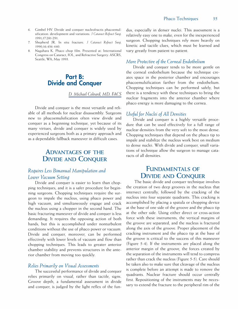
Phaco Techniques 35
6. Gimbel HV. Divide and conquer nucleofractis phacoemul-sification: development and variations. J Cataract Refract Surg. 1991;17:281-291.
7. Shepherd JR. In situ fracture. J Cataract Refract Surg. 1990;16:436-440.
8. Nagahara K. Phaco chop film. Presented at: International Congress on Cataract, IOL, and Refractive Surgery. ASCRS, Seattle, WA; May 1993.
Part B:Divide and Conquer
D. Michael Colvard, MD, FACS
Divide and conquer is the most versatile and reli-able of all methods for nuclear disassembly. Surgeons new to phacoemulsification often view divide and conquer as a beginning technique, yet because of its many virtues, divide and conquer is widely used by experienced surgeons both as a primary approach and as a dependable fallback maneuver in difficult cases.
AdvAntAgesofthedivideAndconqueR
Requires Less Bimanual Manipulation and Lower Vacuum Setting
Divide and conquer is easier to learn than chop-ping techniques, and it is a safer procedure for begin-ning surgeons. Chopping techniques require the sur-geon to impale the nucleus, using phaco power and high vacuum, and simultaneously engage and crack the nucleus using a chopper in the second hand. The basic fracturing maneuver of divide and conquer is less demanding. It requires the opposing action of both hands, but this is accomplished under nonturbulent conditions without the use of phaco power or vacuum. Divide and conquer, moreover, can be performed effectively with lower levels of vacuum and flow than chopping techniques. This leads to greater anterior chamber stability and prevents structures in the ante-rior chamber from moving too quickly.
Relies Primarily on Visual AssessmentsThe successful performance of divide and conquer
relies primarily on visual, rather than tactile, signs. Groove depth, a fundamental assessment in divide and conquer, is judged by the light reflex of the fun-
dus, especially in denser nuclei. This assessment is a relatively easy one to make, even for the inexperienced surgeon. Chopping techniques rely more heavily on kinetic and tactile clues, which must be learned and vary greatly from patient to patient.
More Protective of the Corneal EndotheliumDivide and conquer tends to be more gentle on
the corneal endothelium because the technique cre-ates space in the posterior chamber and encourages phacoemulsification farther from the endothelium. Chopping techniques can be performed safely, but there is a tendency with these techniques to bring the nuclear fragments into the anterior chamber where phaco energy is more damaging to the cornea.
Useful for Nuclei of All DensitiesDivide and conquer is a highly versatile proce-
dure that can be used effectively for a full range of nuclear densities from the very soft to the most dense. Chopping techniques that depend on the phaco tip to impale and stabilize the nucleus work best on medium to dense nuclei. With divide and conquer, small varia-tions of technique allow the surgeon to manage cata-racts of all densities.
fundAmentAlsofdivideAndconqueR
The basic divide and conquer technique involves the creation of two deep grooves in the nucleus that intersect centrally, followed by the cracking of the nucleus into four separate quadrants. This cracking is accomplished by placing a spatula or chopping device at the base of one side of the groove and the phaco tip at the other side. Using either direct or cross-action force with these instruments, the vertical margins of the groove are separated, and the nucleus is fractured along the axis of the groove. Proper placement of the cracking instrument and the phaco tip at the base of the groove is critical to the success of this maneuver (Figure 5-4). If the instruments are placed along the anterior margin of the groove, the forces created by the separation of the instruments will tend to compress rather than crack the nucleus (Figure 5-5). Care should be taken also to make sure that cleavage of the nucleus is complete before an attempt is made to remove the quadrants. Nuclear fracture should occur centrally first. Repositioning of the instruments may be neces-sary to extend the fracture to the peripheral rim of the

36 Chapter 5
nucleus. Once the fracture extends the periphery in all quadrants, the quadrants should mobilize easily. Each quadrant is then engaged by the phaco tip and brought into the pupillary plane in the center of the pupillary axis for safe phacoemulsification.
divideAndconqueR:Astep-by-stepAppRoAch
Step 1. Choose a Keratome That Fits the Phaco Tip. Make sure that the width of the keratome you are using is a perfect fit for your phaco tip. Too small an incision can restrict infusion and re-sult in an incisional burn. Too large of an in-cision will result in excessive outflow of fluid and chamber instability.
Step 2. Create a 5- to 7-mm Capsulorrhexis. Make your capsulorrhexis 5 to 7 mm in diameter. If the capsulorrhexis is too small, mobilization of the quadrants of the nucleus is made diffi-cult. This is particularly true of larger, denser nuclei. Be careful, however. Attempts to make a larger capsulorrhexis may increase the risk of “losing the rhexis” and creating a posterior tear.
Step 3. Hydrodissect. Hydrodissect thoroughly (see Chapter 4). Prior to introducing the phaco tip, place additional viscoelastic in the ante-rior chamber and use a chopper to check the mobility of the nucleus. The nucleus should spin freely within the capsular bag. If it does not, spend the extra time to complete the hy-
drodissection. This is time well spent. Failure to free the nucleus from its cortical attach-ments at this stage of the procedure will force you to struggle with nuclear rotation later and increase the risk of zonular injury.
Step 4. Sculpt the Nucleus. Using moderate flow, low phaco power, and low vacuum, begin the sculpting of the grooves. Low vacuum will al-low you to create the grooves without engag-ing and grabbing the nucleus. Start the groove at the proximal margin of the capsulorrhexis. Carry the groove across to the distal margin. Use phaco power only as you sculpt forward. This will reduce phaco time and help to lim-it the phaco energy released in the anterior chamber (Figure 5-6).
Step 5. Deepen the Grooves. Carry the groove pos-teriorly until you see a good fundus reflex. As a rule of thumb, three times the width of the phaco tip is usually deep enough for most nu-clei. Softer nuclei are often not as thick axi-ally as dense nuclei. Care must be taken not to groove too posteriorly in these eyes.
Step 6. Complete Grooves Before Cracking. Before attempting to crack the nucleus, rotate the nu-cleus 90 degrees and create the second groove, intersecting centrally with the first. The nu-clear plate is easier to rotate if both grooves are made prior to cracking. Also make sure that you do not leave a mound of unsculpted nucleus at the intersection of the two grooves. This can make cracking more difficult and can
Figure 5-4. The phaco tip and the cracking instru-ment should be placed at the base of the groove. Separation of the instruments results in bidirectional forces at the base of the groove and nuclear frac-ture.
Figure 5-5. Placement of the phaco tip and/or the cracking instrument along the anterior margin of the groove results in compression, rather than sepa-ration and fracture, of the posterior nucleus.

Phaco Techniques 37
be avoided by simply carrying each sculpting pass continuously across the intersection (Fig-ure 5-7).
Step 7. Crack the Nucleus Into Quadrants. With the phaco device in irrigation only, place the pha-co tip and a second instrument at the base of the groove, distal to the intersection of the two grooves. Spread apart and gently lift the edges of the groove until a crack is seen posteriorly in the nuclear plate. Reposition the instruments as necessary to complete the crack through the peripheral rim of the nucleus. Rotate the nuclear plate, using a chopper or spatula, and
repeat this maneuver until all four quadrants are freely mobile. Take the time to make sure that disassembly is complete before moving to the next stage of the procedure. As previously noted, the most common error made by begin-ning surgeons is the failure to place both of the instruments at the base of the groove. The spreading of instruments placed too anteriorly in the groove creates vectors that compress rather than separate the posterior aspect of the groove (Figures 5-8 and 5-9).
Step 8. Phaco the Quadrants. After the nuclear plate is disassembled, you can begin the process of
Figure 5-6. Start the groove at the proximal margin of the capsulorrhexis and carry the groove to the distal margin of the rhexis with the phaco device in “sculpt mode” (ie, phaco I—moderate flow, low vacuum, low phaco power).
Figure 5-7. Before attempting to crack the nucleus, rotate the nucleus 90 degrees and create a second groove intersecting the first. Make sure that you do not leave a mound of unsculpted nucleus at the intersection of the grooves.
Figure 5-8. With the phaco device in irrigation only, place the phaco tip and a second instrument at the base of the groove distal to the primary incision.
Figure 5-9. Spread apart and gently lift the edges of the groove until a crack is seen posteriorly in the nuclear plate. Carry this crack across the intersec-tion of the grooves. Repeat this maneuver to disas-semble completely all four quadrants.

38 Chapter 5
removing the individual quadrants of nucleus. Using higher flow and vacuum levels, engage a nuclear quadrant distal to the intersection of the grooves. Right-handed surgeons will find it easier to engage the distal quadrant to the left. Impale the quadrant, wait just a moment for vacuum to increase and then draw the quad-rant to the center of the pupil in the pupillary plane, and begin emulsification. The second instrument should be used to keep the nuclear fragment in the pupillary plane well away from the corneal endothelium (Figures 5-10 and 5-11).
AdditionAltipsFor very dense nuclei, several modifications of
technique are useful. First, retract the phaco irrigation sleeve, exposing slightly more phaco tip. This allows the phaco tip to impale and to cut dense nuclei more efficiently. Second, attempt to make the capsulor-rhexis wider for very dense nuclei. Dense nuclei also tend to be very large nuclei. A small capsulorrhexis makes delivery of large dense nuclear sections into the pupillary plane more difficult. Trypan blue facilitates visualization of the capsule and makes creation of a larger capsulorrhexis safer and easier, especially for beginning surgeons. Third, make the angle of intersec-tion of the grooves 60 and 120 degrees, rather than at 90 degrees. Remove one of the 60-degree “quadrants” first. This smaller segment will slide into the pupil-
lary axis more easily than larger, wider sections of the dense nucleus. Fourth, use a chopping device to break larger sections of hard nucleus into more manageable segments. For the surgeon unaccustomed to using a chopper, this can be done safely once the nucleus is brought into the pupillary plane and away from the posterior capsule.
For very soft nuclei, disassembly in the usual man-ner can be difficult because the nuclear material tends to crumble rather than crack. Fortunately, soft nuclei usually do not need to be cracked. In these cases, once the nucleus is freely mobile after hydrodissection and hydrodelineation, and the grooves have been complet-ed, simply engage each quadrant with the phaco tip in irrigation and aspiration and fold the nuclear segments into the pupillary plane. Ultrasonic energy is often not needed for removal of soft nuclei.
Part C:Phaco Chop Techniques
David F. Chang, MD
Phaco chop refers to an advanced set of phaco techniques that should not be attempted until one has already mastered the divide and conquer method.1,2
Compared to chopping, the latter method is easier to learn because it is much less dependent upon bimanual
Figure 5-10. Engage a quadrant of nucleus distal to the incision with the phaco device in “nucleus removal mode” (ie, phaco II—higher flow, higher vacuum, higher phaco power). Once the nuclear quadrant is impaled, wait for vacuum to increase, then draw the quadrant to the center of the pupil and begin emulsification.
Figure 5-11. With the removal of the last nuclear quadrant and the epinucleus, switch the phaco device to the “epinucleus mode” (ie, phaco III—moderate flow, moderate vacuum, moderate phaco power). This provides maximal control of the cham-ber volume and depth and helps to protect poste-rior capsule at the conclusion of the procedure.

Phaco Techniques 39
instrument coordination. The phaco tip essentially performs a lamellar dissection of the nucleus as the central trough is sculpted. For this reason, experience with divide and conquer phaco teaches resident sur-geons about the relative dimensions and densities of the entire spectrum of nuclei. Furthermore, if attempts at chopping the nucleus fail, divide and conquer becomes a reliable backup technique.
clAssificAtionofchoppingtechniques
Since Kunihiro Nagahara of Japan first introduced the concept of phaco chop in 1993, many different chopping variations have been described.3-5 This wide assortment of modifications can be confusing to resi-dents and transitioning surgeons. For simplification, I first proposed that all chopping methods be conceptu-ally divided into two general categories: horizontal and vertical chopping.3 Both variations share the same advantage of manually fracturing the nucleus but they accomplish this objective in different ways. The classic Nagahara technique exemplifies horizontal chopping, so named because the instrument tips move toward each other in the horizontal plane during execution of the chop (Figure 5-12). In vertical chopping, the two instrument tips move toward each other in the vertical plane as the chop is performed in order to fracture the nucleus (Figure 5-13).
The stop and chop method of Paul Koch is a hybrid of divide and conquer and chopping, which avoids having to make the difficult first unsculpted chop.6 Although chopping the heminuclei does reduce total phaco time, significant ultrasound energy is still necessary in order to sculpt the central trench. For this reason, stop and chop does not deliver the full benefits of nonstop chopping that are listed below. Takayuki Akahoshi and Jochen Kammann pioneered the varia-tion of prechopping the nucleus prior to insertion and use of the phaco tip. The inability to immediately aspi-rate lens debris created with the initial chop, however, may impair visibility for subsequent steps. With dense nuclei it is also difficult to tell how deeply the splitting instrument has penetrated and how close it is to the posterior capsule. Finally, prechopping requires addi-tional steps and instrumentation that are unnecessary when the phaco tip itself is utilized as the chopping platform.
fouRAdvAntAgesofphAcochop
The following four advantages are universal to both horizontal and vertical chop.7
Reduction in Phaco Energy and Heat DeliveryPure chopping techniques eliminate lens sculpting.
Ultrasound energy is not required to subdivide the nucleus and is reserved for the phaco-assisted aspira-tion of mobile fragments. The marked reduction in phaco power and energy is particularly important for brunescent nuclei where the risk of endothelial cell loss, wound burn, and posterior capsule rupture is higher.3,8-11
Reduction in Stress on the Zonules and Capsular Bag
The capsular bag immobilizes the nucleus dur-ing sculpting, and removing a bulky brunescent lens may become problematic for this reason. Unlike a soft nucleus that absorbs instrument pressure like a pillow, a large rigid lens directly transmits instrument forces, such as sculpting, rotation, and cracking directly to the capsular bag and zonules. In contrast, with chop-ping it is the phaco tip that braces and immobilizes the nucleus against the incoming mechanical force of the chopper (see Figures 5-12D and 5-12E). The manual forces, generated by one instrument tip push-ing against the other, replace the need for ultrasound energy to saw through the nucleus. In addition, these manual instrument forces are directed centripetally inward and away from the zonules, rather than out-ward toward the capsule. This significant difference in zonular stress is readily appreciated when chopping and sculpting are compared from the Miyake-Apple viewpoint in cadaver eyes.7
Supracapsular EmulsificationChopping provides many of the same advantages
of so-called supracapsular phaco techniques.12 With phaco chop, emulsification of nuclear fragments is not performed until they have been elevated out of the capsular bag. This allows nearly all phacoemulsifica-tion to be performed centrally in the pupillary plane at a safe distance from both the endothelium and poste-rior capsule (see Figure 5-13K). The phaco tip does not need to travel beyond the central 2- to 3-mm zone of the pupil, which decreases the chance of inadvertently cutting the iris or capsulorrhexis edge in small pupil

40 Chapter 5
cases. In contrast to supracapsular techniques such as phaco flip, however, the all-or-none requirement of prolapsing the entire nucleus anteriorly through the capsulorrhexis is avoided.
Decreased Reliance on the Red ReflexThe increasingly brighter red reflex appearing at
the base of the trench during sculpting allows us to judge the depth of the phaco tip and its proximity to the posterior capsule. In contrast, the instrument maneuvers performed during chopping are more tactile and kinesthetic. Because it is not necessary to directly visualize the precise depth of the phaco tip, chopping is advantageous in the presence of a poor red reflex, such as with diminished corneal clarity, smaller pupils, and mature nuclear or cortical cataracts (see Figure 5-12).
In addition to improved surgical efficiency, safety is enhanced by these aforementioned attributes of reduced phaco power, reduced zonular stress, decreased reliance on the red reflex, and the supracapsular and central location of emulsification. These universal advantages that both horizontal and vertical chopping share make them optimal techniques for difficult and compli-cated cases. The improved ability to handle brunescent nuclei, white cataracts, loose zonules, posterior polar cataracts, crowded anterior chambers, capsulorrhexis tears, and small pupils should be the primary motiva-tion for a divide and conquer surgeon to transition to phaco chop.3,4,13,14
hoRizontAlphAcochopThe horizontal chopping technique relies upon
compressive force to fracture the nucleus. This exploits natural fracture planes in the lens created by the lamel-lar orientation of the lens fibers. Hydrodelineation is particularly important for horizontal chopping because it decreases the diameter of the endonucleus that must be peripherally hooked and divided by the chopper.3 In addition, the soft epinucleus provides a working zone for the horizontal chopper where it can be manipulated peripheral to the endonuclear equator without overly distending or tearing the capsular bag. Finally, the epi-nuclear shell restrains the posterior capsule from tram-polining toward the phaco tip as the final endonuclear fragments are emulsified.
hoRizontAlchop:Astep-by-stepAppRoAch
Step 1. Place the Chopper Tip in the Epinuclear Space. The critical first step is to hook the
nuclear equator with the chopper tip within the epinuclear space of the peripheral capsular bag prior to initiating the horizontally directed chop (see Figures 5-12A through 5-12C).3 Prior to placing the chopper, the central anterior epi-nucleus should be aspirated with the phaco tip (see Figure 5-12A). This allows one to better vi-sualize and estimate the size of the endonucleus and the amount of separation between the en-donucleus and the surrounding capsular bag.
The chopper tip touches and maintains con-tact with the anterior endonucleus as it travels peripherally beneath the opposing capsulor-rhexis edge (see Figure 5-12A). This ensures that the chopper tip stays within the bag as it descends to hook the endonucleus peripher-ally. Although some surgeons tilt the chopper tip sideways to reduce its profile as it passes underneath the capsular edge, this is generally unnecessary unless the capsulorrhexis diameter is small. Instead, the horizontal chopper tip can remain in a vertical upright orientation because, like an elastic waistband, the capsulorrhexis will stretch to accommodate it without tearing (see Figure 5-12B).
Once it reaches the epi/endonuclear junction, the vertically oriented chopper tip descends into the epinuclear space alongside the edge of the endonucleus (see Figure 5-12C). This step is easiest to perform with a smaller endonucleus surrounded by a large epinucleus. Nudging the nucleus with the chopper confirms that it has hooked the equator and that it is within, rather than outside, the capsular bag. Trypan blue dye improves visualization of the anterior capsule for this step and is a useful teaching aid (see Figures 5-12A through 5-12C).15
Step 2. Impale and Immobilize the Nucleus With the Phaco Tip. Next, one must deeply impale and immobilize the nucleus with the phaco tip (see Figure 5-12D). The phaco tip should be di-rected vertically downward and positioned as proximally as possible in order to maximize the amount of nucleus located in the path of the chopper. If the depth of the phaco tip is too shallow, sufficient compression of the central nucleus cannot occur. Once impaled, the phaco tip holds and stabilizes the nucleus with vacu-um in foot pedal position 2.
Step 3. Execute the First Chop. The chopper tip is drawn directly toward the phaco tip, and upon contact, the two tips are moved directly apart

Phaco Techniques 41
Figure 5-12D. Phaco tip impales centrally with 320 mmHg vacuum.
Figure 5-12E. Chopper cuts toward the fixating phaco tip.
Figure 5-12F. Instrument tips separate upon contact to split the nucleus in half.
Figure 5-12A. Horizontal chop of mature white cataract following trypan blue capsular stain-ing. Chang microfinger-style horizontal chopper (Katena, ASICO) maintaining contact with anterior endonuclear surface.
Figure 5-12C. The horizontal chopper tip drops into the epinuclear space and hooks the nuclear equator.
Figure 5-12B. The horizontal chopper passes beneath distal capsulorrhexis edge while oriented vertically.

42 Chapter 5
from each other (see Figures 5-12E and 5-12F). This separating motion occurs along an axis perpendicular to the chopping path and propa-gates the fracture across the remaining nucleus located behind and beneath the phaco tip. The denser and bulkier the endonucleus, the further the hemisections must be separated in order to cleave the connecting nuclear attach-ments. Thanks to the elasticity of the capsulor-rhexis, a wide momentary separation of large heminuclei will not tear the capsular bag.
In order for the initial chop to succeed, enough of the central endonucleus must lie within the path of the chopper. Particularly if the anterior epinucleus has not been removed, it is easy to misjudge the depth of the two instrument tips. If the phaco tip is too superficial or too cen-tral, or the chopper tip is not kept deep enough throughout the course of the chop, the nucleus will not fracture.3 Instead, the chopper will only score or scratch the anterior surface. The larger and denser the nucleus is, the more im-portant and more difficult proper positioning of the two instrument tips becomes. A coun-terproductive but natural tendency to elevate the chopper tip during the chop arises from a fear of perforating the posterior capsule.
The tactile “feel” of the horizontal chop will vary significantly as one proceeds up along the spectrum of nuclear density. A soft nucleus has the consistency of soft ice cream and no resis-tance is felt as the chopper is moved. With a medium-density nucleus, the chopper encoun-ters slight resistance, indicating that some com-
pression is taking place. This resistance is much greater while chopping a dense nucleus, where the compressive force is followed by a sudden snap as the initial split occurs. To develop suf-ficient compressive force, one must move the chopper tip directly toward the phaco tip until they touch before commencing the sideways separating motion. Veering the chopper tip to the left as it approaches the phaco tip limits the compressive force and causes the nucleus to swivel.
Step 4. Remove the First Chopped Fragment. Upon completion of the initial chop, the nucleus should be divided in half. After rotating the bi-sected nucleus 30 to 45 degrees in a clockwise direction, repeating the same steps of hooking the equator and chopping toward the phaco tip creates a small, pie-shaped fragment (see Fig-ures 5-12G through 5-12K). The strong grip afforded by high vacuum facilitates elevation of this first piece out of the bag. Insufficient holding force may be the result of inadequate vacuum settings or failure to completely oc-clude the tip. Burst mode enhances the phaco tip’s purchase of a firm nuclear piece by better preserving the initial seal around the opening.
Step 5. Chop and Phaco Additional Nuclear Seg-ments. Every subsequent chop is a repetition of these steps, and each wedge-shaped piece is emulsified as soon as it is created. Once half of the capsular bag is vacated, the phaco tip can impale and transport the remaining heminucle-us toward the center of the pupil. This allows the horizontal chopper tip to be positioned
Figure 5-12G. After rotating the nucleus 45 degrees clockwise, the chopper makes a second pass beneath the anterior capsule.
Figure 5-12H. Chopper tip descends to hook the nucleus.

Phaco Techniques 43
under direct visualization against the outer edge of the heminucleus and without having to pass it beneath the anterior capsule.
One advantage of horizontal chopping is that larger nuclear pieces can be subdivided into smaller and smaller fragments. The size of the pieces should be kept proportional to the size of the phaco tip opening. Poor followability and excessive chatter of firm fragments en-gaged by the phaco tip may indicate that they are too large. Because of their greater overall dimensions, brunescent nuclei will need to be chopped into many more pieces than softer nuclei.
veRticAlphAcochop:Astep-by-stepAppRoAch
For each of the two different chopping techniques, one should position the more important instrument first. This means initiating horizontal chop by first hooking the nucleus with the chopper tip. With verti-cal chop, the nucleus should first be impaled with the phaco tip. Step 1. Impale the Nucleus With the Phaco Tip.
Similar to horizontal chop, it is helpful to first aspirate the anterior epinucleus (see Figure 5-13A). Whereas sufficient depth of the chop-per tip is the key for horizontal chopping, an adequately deep purchase with the phaco tip is the most crucial factor in vertical chop (see Figure 5-13B).3 This is because the centrally impaled phaco tip must completely immobilize the nucleus against the incoming sharp chop-per tip in order to generate enough shearing force to fracture it. The need for a strong pur-chase is also why high vacuum and burst mode are more critical for vertical than for horizon-tal chop.
Step 2. Incise the Nucleus With the Vertical Chop-per, Then Lift With the Phaco Tip. Whereas the horizontal chopper moves inward from the periphery toward the phaco tip, the vertical chopper is used like a spike descending from above to incise the nucleus just anterior to the centrally impaled phaco tip (see Figure 5-13C). Depressing the sharpened chopper tip down-ward while simultaneously lifting the nucleus slightly upward imparts a shearing force that fractures the nucleus (see Figures 5-13D and
Figure 5-12I. Phaco tip impales and immobilizes the nucleus with 320 mmHg vacuum.
Figure 5-12J. The second chop is executed in the horizontal plane.
Figure 5-12K. Sideways separation of the instru-ments fractures the lens and creates the first frag-ment. Note the grip afforded by 320 mmHg of vacuum.
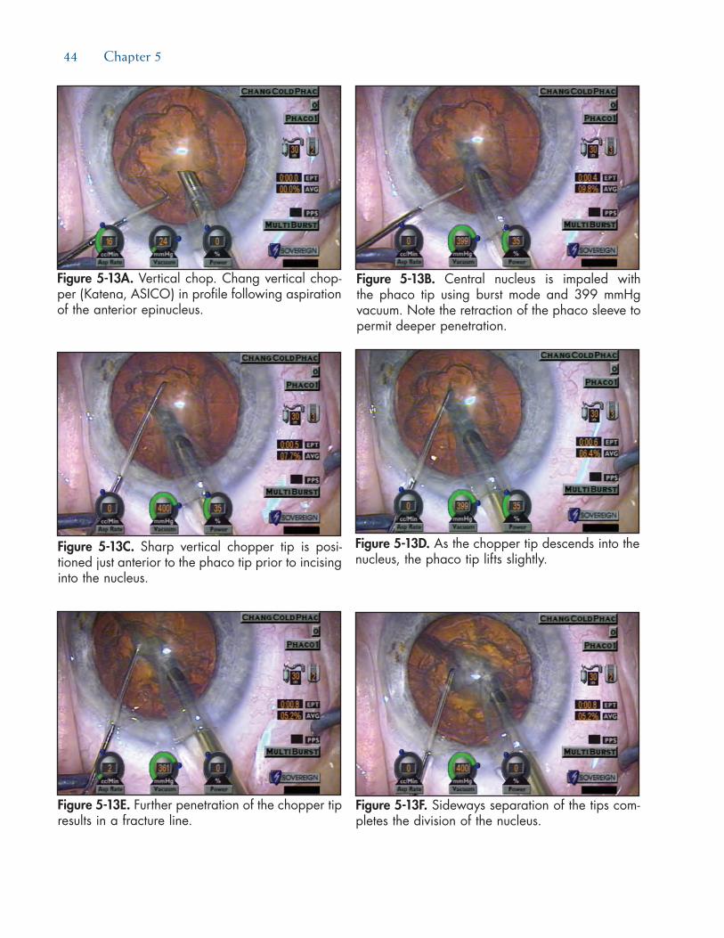
44 Chapter 5
Figure 5-13A. Vertical chop. Chang vertical chop-per (Katena, ASICO) in profile following aspiration of the anterior epinucleus.
Figure 5-13B. Central nucleus is impaled with the phaco tip using burst mode and 399 mmHg vacuum. Note the retraction of the phaco sleeve to permit deeper penetration.
Figure 5-13C. Sharp vertical chopper tip is posi-tioned just anterior to the phaco tip prior to incising into the nucleus.
Figure 5-13D. As the chopper tip descends into the nucleus, the phaco tip lifts slightly.
Figure 5-13E. Further penetration of the chopper tip results in a fracture line.
Figure 5-13F. Sideways separation of the tips com-pletes the division of the nucleus.

Phaco Techniques 45
5-13E). This contrasts with the compressive force produced by horizontal chopping. After initiating a partial-thickness split, the embed-ded instrument tips are used to pry the two hemisections apart (see Figure 5-13F). Just as with horizontal chopping, this sideways sepa-ration of the instrument tips extends the frac-ture deeper until the remainder of the nucleus is cleaved in half. The vertically chopped edg-es appear sharp, like pieces of broken glass, be-cause there is none of the crushing force that characterizes horizontal chop.
Step 3. Chop All Fragments Before Removing Them. In horizontal chop, sequentially removing each newly created fragment provides the chopper with increased working space within the cap-sular bag. In contrast, one need not remove the vertically chopped pieces until the entire nu-cleus is fragmented. This is because the pres-ence of the adjacent interlocking pieces better stabilizes and immobilizes the section that is being chopped (see Figures 5-13G through 5-13J). In contrast to horizontal chopping, the vertical chopper is never placed peripheral to
the equator of the nucleus. Therefore, remov-ing fragments to vacate space within the cap-sular bag early on provides no real advantage (see Figure 5-13K).
compARinghoRizontAlAndveRticAlchop—
Whichtechnique?Although I use both techniques with equal fre-
quency, each employs different mechanisms that have complimentary advantages and disadvantages. It is worth learning and utilizing both variations for this reason. Vertical chopping requires less dexterity of the nondominant hand and is therefore easier for most transitioning surgeons to learn. Vertical chopping also requires a nucleus that is brittle enough to be snapped in half, which means that it is ineffective for soft nuclei.3 The ability of the horizontal chopper tip to easily slice through a soft nucleus instead of fracturing it makes horizontal chopping the method of choice for these cases.
Horizontal chop is also my preference for loose zonule cases, such as traumatic cataracts. Because
Figures 5-13G through 5-13I. After rotating the nucleus 30 degrees counterclockwise, the nucleus is impaled with 400 mmHg vacuum. The vertical chopper descends into the nucleus, resulting in propagation of the fracture.
G H
I

46 Chapter 5
of the oppositely directed, compressive instrument forces, horizontal chop produces the least amount of nucleus movement or tilt. Finally, horizontal chop is more effective for subdividing smaller, mobile nuclear fragments—particularly brunescent ones. Attempting to vertically chop and shear such fragments will often dislodge the small piece instead. Trapping and then crushing fragments between the horizontal chopper and the phaco tip will immobilize and divide them most effectively.
The limitation of horizontal chopping is in its relative inability to transect thicker brunescent nuclei. Indeed, horizontal chopping should never be utilized in the absence of an epinuclear shell since there will be insufficient space in the peripheral bag to accommo-date the chopper. Frequently, the horizontally directed path of the chopper is not deep enough to sever the leathery posterior plate of an ultra-brunescent nucleus. If this occurs, the partially chopped pieces will still be connected at the apex, like flower petals. In such cases, one should try to inject a dispersive viscosurgical device (OVD) through one of the incomplete cracks in the posterior plate to distance it from the posterior capsule. Since a dispersive OVD resists aspiration, the surgeon can attempt to carefully phaco through the remaining connecting bridges.
Because vertical chop is more consistently able to fracture the leathery posterior plate, it is well suited for denser nuclei.3 With an ultra-brunescent lens, the vertical chopper should approach the embedded phaco tip from a diagonal angle. This provides more of a horizontal vector force that pushes the nucleus against the tip, while the downward vertical vec-
tor force initiates the fracture. This “diagonal” chop therefore combines the mechanical advantages of both strategies. With denser nuclei, one should also begin by sculpting a small pit or half trench centrally.16-18 By entering at the base of the pit, the phaco tip can impale more deeply than would have been possible without this preliminary debulking. Retracting the irrigation sleeve further maximizes penetration. One should later switch to horizontal chopping for subdividing brunes-cent fragments into smaller pieces.18 This will improve followability and reduce endothelial cell loss due to chatter and particle turbulence at the phaco tip.
stepWisegAmeplAnfoRleARninghoRizontAlchop
Of the two different techniques, the greater requirement for bimanual dexterity with the chopper makes horizontal chopping more difficult to learn. The most difficult steps are the initial ones—the first chop across the entire unsculpted diameter of the nucleus and removal of the first segment. Each subsequent step becomes progressively easier as additional space is vacated within the capsular bag. Logically, the saf-est strategy would allow surgeons to learn the steps in the reverse order, starting with the easiest maneuvers first.3,15 In the proposed game plan, the component skills can be isolated, developed, and rehearsed while performing divide and conquer or stop and chop cases. These principles and the same stepwise learning pro-gression are equally applicable to mastering vertical phaco chop.
Figure 5-13J. With high vacuum (400 mmHg) grip of one segment, the two instrument tips pry the pieces apart. The sharp edges of the fragments result from a shearing force.
Figure 5-13K. After vertically chopping the entire nucleus into multiple pieces, the fragments are elevated out of the capsular bag.
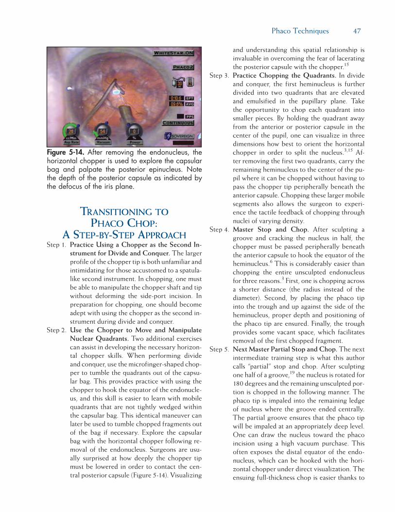
Phaco Techniques 47
tRAnsitioningtophAcochop:
Astep-by-stepAppRoAchStep 1. Practice Using a Chopper as the Second In-
strument for Divide and Conquer. The larger profile of the chopper tip is both unfamiliar and intimidating for those accustomed to a spatula-like second instrument. In chopping, one must be able to manipulate the chopper shaft and tip without deforming the side-port incision. In preparation for chopping, one should become adept with using the chopper as the second in-strument during divide and conquer.
Step 2. Use the Chopper to Move and Manipulate Nuclear Quadrants. Two additional exercises can assist in developing the necessary horizon-tal chopper skills. When performing divide and conquer, use the microfinger-shaped chop-per to tumble the quadrants out of the capsu-lar bag. This provides practice with using the chopper to hook the equator of the endonucle-us, and this skill is easier to learn with mobile quadrants that are not tightly wedged within the capsular bag. This identical maneuver can later be used to tumble chopped fragments out of the bag if necessary. Explore the capsular bag with the horizontal chopper following re-moval of the endonucleus. Surgeons are usu-ally surprised at how deeply the chopper tip must be lowered in order to contact the cen-tral posterior capsule (Figure 5-14). Visualizing
and understanding this spatial relationship is invaluable in overcoming the fear of lacerating the posterior capsule with the chopper.15
Step 3. Practice Chopping the Quadrants. In divide and conquer, the first heminucleus is further divided into two quadrants that are elevated and emulsified in the pupillary plane. Take the opportunity to chop each quadrant into smaller pieces. By holding the quadrant away from the anterior or posterior capsule in the center of the pupil, one can visualize in three dimensions how best to orient the horizontal chopper in order to split the nucleus.3,15 Af-ter removing the first two quadrants, carry the remaining heminucleus to the center of the pu-pil where it can be chopped without having to pass the chopper tip peripherally beneath the anterior capsule. Chopping these larger mobile segments also allows the surgeon to experi-ence the tactile feedback of chopping through nuclei of varying density.
Step 4. Master Stop and Chop. After sculpting a groove and cracking the nucleus in half, the chopper must be passed peripherally beneath the anterior capsule to hook the equator of the heminucleus.6 This is considerably easier than chopping the entire unsculpted endonucleus for three reasons.3 First, one is chopping across a shorter distance (the radius instead of the diameter). Second, by placing the phaco tip into the trough and up against the side of the heminucleus, proper depth and positioning of the phaco tip are ensured. Finally, the trough provides some vacant space, which facilitates removal of the first chopped fragment.
Step 5. Next Master Partial Stop and Chop. The next intermediate training step is what this author calls “partial” stop and chop. After sculpting one half of a groove,19 the nucleus is rotated for 180 degrees and the remaining unsculpted por-tion is chopped in the following manner. The phaco tip is impaled into the remaining ledge of nucleus where the groove ended centrally. The partial groove ensures that the phaco tip will be impaled at an appropriately deep level. One can draw the nucleus toward the phaco incision using a high vacuum purchase. This often exposes the distal equator of the endo-nucleus, which can be hooked with the hori-zontal chopper under direct visualization. The ensuing full-thickness chop is easier thanks to
Figure 5-14. After removing the endonucleus, the horizontal chopper is used to explore the capsular bag and palpate the posterior epinucleus. Note the depth of the posterior capsule as indicated by the defocus of the iris plane.
48 Chapter 5
the partial groove having already thinned out the proximal nucleus (like a scored aspirin tab-let). Unlike Dewey’s original description, this “partial” stop and chop technique emphasizes the key skill of hooking the nuclear equator with the chopper, which alternatively can be performed prior to impaling the nucleus with the phaco tip.15
Step 6. Proceed to “Pure” Horizontal Chop. After mastering “classic” and “partial” stop and chop, one is now ready to progress to pure horizontal chopping in which the entire nuclear diameter is cleaved in half without any sculpting (see Figures 5-12A through 5-12F).3 For horizontal chop, softer and smaller endonuclei should be mastered before progressing to firmer and larg-er endonuclei. Horizontal chopping in particu-lar requires significant bimanual dexterity, and the chopper must be maneuvered like a row-boat oar with the side-port incision serving as the stationary fulcrum. Just like a golfer prac-tices swings, a helpful exercise is to perform “practice” chops in the anterior chamber above the nucleus prior to initiating the first chop.15 This allows the surgeon to verify proper orien-tation of the chopper tip and shaft as he or she practices the full sequence of motions. If the surgeon finds that the chopper is distorting or displacing the incision or that the hand posi-tion is awkward or uncomfortable, it is better to correct the problem at this point rather than after the chopper is inside the capsular bag.
summARyHorizontal and vertical chopping are variations that
rely upon different mechanisms to provide complemen-tary advantages and common benefits. Mastering both methods affords surgeons greater flexibility in dealing with the wide range of nuclear densities and other sur-gical variables.3,17 With dense lenses, one may employ both techniques during the same case.17 Transitioning surgeons should consider learning vertical chopping first. In addition to increasing surgical efficiency for routine cases, chopping provides an increased margin of safety for complicated cases (see Figure 5-12).3,13,14
A more detailed discussion of chopping tech-niques is available in the author’s book Phaco Chop: Mastering Techniques, Optimizing Technology, and Avoiding Complications,7 from which much of this content was excerpted.
RefeRences1. Shepherd JR. In situ fracture. J Cataract Refract Surg.
1990;16:436-440.2. Gimbel HV. Divide and conquer nucleofractis phacoemul-
sification: development and variations. J Cataract Refract Surg. 1991;17:281-291.
3. Chang DF. Converting to phaco chop: why and how. Ophthal-mic Practice. 1999;17(4):202-210.
4. Vasavada AR, Desai JP. Stop, chop, chop, and stuff. J Cataract Refract Surg. 1996;22:526-529.
5. Arshinoff SA. Phaco slice and separate. J Cataract Refract Surg. 1999;25:474-478.
6. Koch PS, Katzen LE. Stop and chop phacoemulsification. J Cataract Refract Surg. 1994;20:566-570.
7. Chang DF. Why learn chopping? In: Chang DF, ed. Phaco Chop: Mastering Techniques, Optimizing Technology, and Avoiding Complications. Thorofare, NJ: SLACK Incorporated; 2004.
8. Fine IH, Packer M, Hoffman RS. Use of power modulations in phacoemulsification. Choo-choo chop and flip phacoemulsi-fication. J Cataract Refract Surg. 2001;27:188-197.
9. Pirazzoli G, D’Eliseo D, Ziosi M, Acciarri R. Effects of phaco-emulsification time on the corneal endothelium using phaco-fracture and phaco chop techniques. J Cataract Refract Surg. 1996;22:967-969.
10. DeBry P, Olson RJ, Crandall, AS. Comparison of energy re-quired for phaco-chop and divide and conquer phacoemulsi-fication. J Cataract Refract Surg. 1998;24:689-692.
11. Wong T, Hingorani M, Lee V. Phacoemulsification time and power requirements in phaco chop and divide and conquer nucleofractis techniques. J Cataract Refract Surg. 2000;26:1374-1378.
12. Maloney WF, Dillman DM, Nichamin LD. Supracapsular phacoemulsification: a capsule-free posterior chamber ap-proach. J Cataract Refract Surg. 1997;23:323-328.
13. Chang DF. Prevention pearls and damage control. In: Fish-kind W, ed. Complications in Phacoemulsification. New York, NY: Thieme; 2002.
14. Chang DF. Phaco strategies for complicated cataracts. In: Chang DF, ed. Phaco Chop: Mastering Techniques, Optimizing Tech-nology, and Avoiding Complications. Thorofare, NJ: SLACK In-corporated; 2004.
15. Chang DF. Transitioning to phaco chop. In: Chang DF, ed. Phaco Chop: Mastering Techniques, Optimizing Technology, and Avoid-ing Complications. Thorofare, NJ: SLACK Incorporated; 2004.
16. Vasavada AR, Singh R. Step-by-step chop in situ and separa-tion of very dense cataracts. J Cataract Refract Surg. 1998;24:156-159.
17. Vanathi M, Vajpayee RB, Tandon R, et al. Crater-and-chop technique for phacoemsulsification of hard cataracts. J Cata-ract Refract Surg. 2001;27:659-661.
18. Chang DF. Comparing and integrating horizontal and vertical chopping. In: Chang DF, ed. Phaco Chop: Mastering Techniques, Optimizing Technology, and Avoiding Complications. Thorofare, NJ: SLACK Incorporated; 2004.
19. Dewey S. Transition to chop: a non-impaling technique (vid-eo). American Academy of Ophthalmology Annual Meeting, 2003.

Phaco Techniques 49
Part D:Bimanual Vertical Chop Technique
Mark Packer, MD, FACS; I. Howard Fine, MD; and Richard S. Hoffman, MD
Recent advances with the AMO (Santa Ana, CA) WhiteStar “micro-pulsed” technology markedly reduce the risk of thermal injury to the eye and allow today’s surgeon to perform microincisional bimanual phacoemulsification. In our experience, separating the inflow from the outflow in a phaco procedure has sev-eral advantages. These include superior control of the globe, enhanced cortical cleaving hydrodissection, use of irrigation fluid as an instrument to mobilize mate-rial, and reduced effective phaco time.
bimAnuAlveRticAlchop:Astep-by-stepAppRoAch
Step 1. Create Microincisions Sized Precisely to Match the Phaco Instrumentation. To begin the bimanual vertical chop technique, start with a paracentesis type of incision to the left and the right, constructed with a trapezoidal blade. The blade selected should create an inci-sion that measures 1.2 mm internally, precisely the size required for 20-gauge instrumentation used for bimanual microincision phacoemulsi-fication. Fill the anterior chamber with a dis-
persive viscoelastic that will remain in the eye during our high-flow, high-vacuum chop tech-nique.
Step 2. Perform Capsulorrhexis Using Microincision Forceps. The capsulorrhexis may begin with either a linear central capsular tear created with a capsulotomy needle or with a simple pinch of the central capsule, using microinci-sional forceps. These forceps are then used to perform a continuous curvilinear capsulotomy through the small side-port incisions on the right or the left. The microincision forceps (MST, Redmond, WA), designed to open and close through a 1.2-mm incision, allow excel-lent control of the capsulorrhexis; addition-ally, the small incisions facilitate control of the capsulorrhexis because the viscoelastic does not exit the eye. Loss of chamber stability, caused by the outflow of viscoelastic material through a larger standard phaco incision, can make the creation of a round central capsulor-rhexis more difficult. One of the advantages of microincision techniques is that the cham-ber remains very stable during the completion of the capsulorrhexis. This allows us to better control the size, diameter, and position of our capsulorrhexis.
Step 3. Hydrodissect and Hydrodelineate the Nu-cleus. Cortical cleaving hydrodissection is performed by tenting up the anterior capsule and injecting balanced salt solution under the rim of the capsule. A fluid wave then advances completely across the posterior capsule. Fre-quently, the fluid wave is trapped temporarily between the lens and the posterior capsule, which causes the lens to prolapse anteriorly. Repositioning the lens by pushing posteriorly with the cannula in the center decompresses the fluid that is trapped, forcing it around the equator and lysing the corticocapsular connec-tions. The lens is then rotated to make sure it is free. Hydrodelineation can be carried out by embedding the tip of the cannula in the center of the lens and advancing until the resistance of the endonucleus is encountered. A slight to-and-fro motion of the cannula will create a small space into which balanced salt solution is injected. The fluid flows between the endonu-cleus and the epinucleus, forming the golden ring seen in Figure 5-15.
Figure 5-15. The golden ring formed by hydrode-lineation is clearly visible as the phaco needle is embedded in the nucleus. The nucleus is held firmly with high vacuum in foot pedal position 2. Note that aspiration flow and power are at zero and vacuum is at maximum with occlusion.
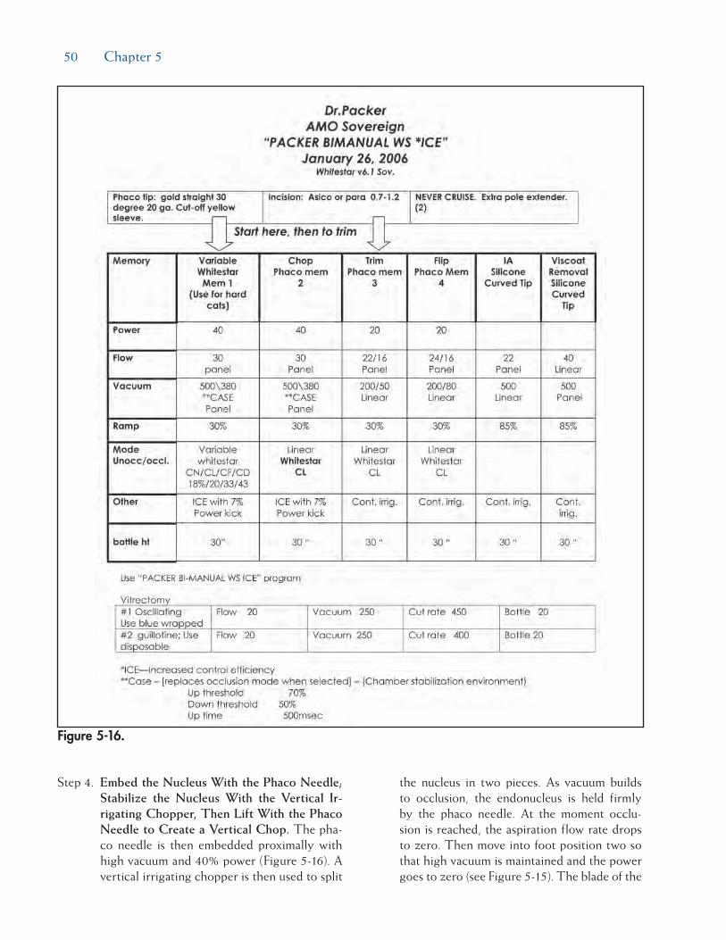
50 Chapter 5
Step 4. Embed the Nucleus With the Phaco Needle; Stabilize the Nucleus With the Vertical Ir-rigating Chopper, Then Lift With the Phaco Needle to Create a Vertical Chop. The pha-co needle is then embedded proximally with high vacuum and 40% power (Figure 5-16). A vertical irrigating chopper is then used to split
the nucleus in two pieces. As vacuum builds to occlusion, the endonucleus is held firmly by the phaco needle. At the moment occlu-sion is reached, the aspiration flow rate drops to zero. Then move into foot position two so that high vacuum is maintained and the power goes to zero (see Figure 5-15). The blade of the
Figure 5-16.

Phaco Techniques 51
irrigating vertical chopper is brought down just distal to the phaco tip as the phaco tip is lifted slightly. As a full-thickness cleavage plane develops, dividing the nucleus in two, separate the chopper and the phaco needle to ensure a complete chop (Figure 5-17).
Step 5. Chop and Phaco Additional Nuclear Seg-ments. The lens can then be rotated with the irrigating chopper so that the first heminucleus can be chopped. If there is a disparity in size, the larger half is moved distally and chopped next. The phaco needle is now embedded to the right using high vacuum and low levels of power. The surgeon may then either make additional chops or, alternatively, a quadrant-
sized piece may be chopped off and consumed (Figure 5-18). The remaining quadrant of the first heminucleus may then be impaled with the phaco tip and aspirated (Figure 5-19).
To address the second half of the nucleus, it is first rotated with the irrigating chopper so that it is in the distal capsule. The phaco needle is embedded in the smaller heminucleus and it is subdivided with the irrigating chopper, again using high vacuum and low levels of power (Figure 5-20). As the final quadrant is grasped and pulled centrally for aspiration, the sharp blade of the irrigating chopper is turned side-ways as a safety precaution (Figure 5-21).
Step 6. Aspirate the Epinucleus. To address the epi-nucleus, reduce phaco settings, turning down both the vacuum and flow rate. The rim of the epinucleus is then trimmed, disallowing the epinucleus from flipping into the phaco needle with the stream of irrigation fluid or the irrigating chopper itself. The advantage of the trimming procedure lies in the aspira-tion of cortical material from behind the epi-nuclear shell. In most cases, this step eliminates the need for irrigation/aspiration prior to IOL insertion. Once three quadrants of the epi-nuclear shell have been rotated and trimmed, the final quadrant is used to flip the epinuclear bowl into the phaco needle (Figure 5-22). Fol-lowing aspiration of the epinucleus the capsule is often entirely clean of cortex (Figure 5-23).
Figure 5-17. The phaco needle is pulled up and to the right as the chopper blade slices into the nucleus just in front of the needle and is then pulled to the left and down, effectively hemisecting the cataract.
Figure 5-19. The remaining quadrant of the hemi-nucleus is lifted and consumed. Note the rim of intact epinucleus (visible from about 9 o’clock to 1 o’clock), which serves to protect the capsule.
Figure 5-18. Following a second chop, the first quadrant is lifted and pulled centrally where it is consumed with high vacuum and low levels of ultrasound power application.

52 Chapter 5
Step 7. Enlarge the Microincision or Create a New Incision for IOL Implantation. The incision for the lens is constructed with the differen-tially beveled 3D Blade (Rhein Medical, Tam-pa, FL), which reproducibly creates a 2.5-mm incision at the shoulders. The relatively larger incision (approximately 2.5 mm) that is con-structed for IOL insertion seals quite nicely because it has been only minimally disturbed. We always perform stromal hydration at all the incisions and perform a Seidel test at the con-clusion of the case. Careful attention to sealing clear corneal incisions may be critical for the prevention of postoperative infection.
summARyBimanual phaco with a vertical chop technique
allows efficient lens extraction with rapid visual reha-bilitation. Tangible benefits of separating inflow from outflow include enhanced cortical cleaving hydrodis-section, use of irrigation fluid as an instrument to mobilize material, and reduced effective phaco time.
Figure 5-20. Following rotation and chopping of the remaining heminucleus, the first quadrant is consumed.
Figure 5-21. The final quadrant is consumed. The irrigation flow is maintained posteriorly to keep the capsule well away from the phaco needle. The chop element is turned to avoid contact with the capsule.
Figure 5-22. The rim of the epinuclear shell is grasped distally and pulled centrally, flipping the epinucleus and allowing its rapid consumption.
Figure 5-23. Because the cortex was consumed with the epinucleus, the capsule is pristine and ready for IOL insertion. The patient’s asteroid hya-losis is clearly visible.

53
Every cataract surgeon should have a game plan for when and how to perform an anterior vitrectomy following posterior capsule rupture. This chapter will review the goals, the indications, and the techniques of an anterior vitrectomy. Understanding and mentally rehearsing these strategies will better prepare cataract surgeons to make correct decisions amidst the stress of an unexpected complication.
Managing Posterior CaPsular ruPture—
a steP-by-steP aPProaChStep 1. Attempt to Avoid Vitreous Loss Following
Posterior Capsular Rupture. In many instanc-es with a torn posterior capsule, it is possible to avoid rupturing the hyaloid face. The surgeon must avoid immediately withdrawing the pha-co tip upon recognizing a posterior capsular defect. This abruptly unplugs the incision and allows the anterior chamber to collapse. The sudden posterior pressure gradient will rupture an intact hyaloid face, and vitreous will pro-lapse to the incision, expanding the capsular rent in the process.
This undesirable cascade of events can be averted by filling the anterior chamber with a dispersive ophthalmic viscosurgical device (OVD) such as Viscoat (Alcon, Fort Worth, TX) or Healon D (AMO, Santa Ana, CA), prior to removing the phaco tip. Dispersive OVDs are preferable to cohesive OVDs in the face of a capsule tear. This is because disper-sive OVDs are better at maintaining space and resisting aspiration during phacoemulsification and irrigation/aspiration ([I/A] see Chapter 11). As the dispersive OVD is injected through the side-port opening, the surgeon moves from foot pedal position 1 to 0. Once the chamber is filled with OVD, the posterior capsule can-not bulge forward as the incision is unplugged. If one resumes phacoemulsification or cortical cleanup, the same maneuver must be repeated whenever the instruments are removed.
Step 2. Manage the Nucleus Following Posterior Capsule Rupture. Early recognition of pos-terior capsule rupture is the key to avoiding a dropped nucleus. It is much easier to remove the nucleus while it remains anterior to the posterior capsule defect. Because they ap-proach the nucleus from above, subsequent
Chapter
Managing the Broken Posterior Capsule
David F. Chang, MD
6

54 Chapter 6
instrument and fluidic forces will eventually ex-pand an unrecognized capsular defect enough to allow the nucleus to sink posteriorly.
One must often rely upon indirect clues to rec-ognize a posterior capsular defect because the iris and the nucleus obscure the zonular and posterior capsular anatomy. Sudden deepening of the chamber with momentary expansion of the pupil, the transitory appearance of a clear red reflex in the periphery, and the inability to rotate a previously mobile nucleus can all indi-cate capsular or zonular rupture. More obvious and ominous signs would be excessive tipping or lateral mobility of the nucleus or partial pos-terior descent of the nucleus.
If the remaining nucleus or fragments can be elevated into the anterior chamber with a dis-persive OVD, one can insert a trimmed Sheet’s glide through the phaco incision to serve as an artificial posterior capsule, as described by Marc Michelson.1 The glide can prevent lens material from dropping posteriorly and will shield the phaco tip from aspirating vitreous from below. The incision should be slightly widened to accommodate inserting the phaco tip above and alongside the glide. Maneuvers of the phaco tip should be minimized to avoid simultaneously moving the glide. This is one advantage of using bimanual microincisional phaco instrumentation through separate 1.2-mm side ports in this situation if the surgeon is adept at this technique.
Step 3. If Necessary, Rescue the Partially Descended Nucleus, Using the Viscoat PAL Technique. How far the nucleus initially descends through a capsular defect will depend upon the vitre-ous anatomy. If the vitreous is too liquefied, the nucleus will rapidly sink to the retina, pre-cluding any response by the cataract surgeon. Alternatively, the nucleus may partially de-scend onto an intact hyaloid face (Figure 6-1). Such slight posterior displacement can be very subtle. Finally, if the hyaloid face is ruptured, the nucleus may tip or partially descend until it is suspended and supported by formed vitre-ous. In this situation, a rescue technique may be possible.
Although tempting to do so, the worst tactic for recovering a partially descended nucleus is to try to chase and spear it with the phaco tip. Lacking the normal capsular barrier, the
posteriorly directed irrigation flow will flush more vitreous forward, expanding the rent and propelling the nucleus away. Attempting to emulsify or aspirate the nucleus may ensnare vitreous into the large diameter phaco tip. Ap-plying suction and ultrasound following vitre-ous incarceration can produce a giant retinal tear.
The safer alternative is to elevate the nucleus into the pupillary plane or anterior chamber from below. There are numerous obstacles to doing this, however. First, the pupil or capsulor-rhexis diameter may be quite small, which may have predisposed the eye to capsular rupture in the first place. A small pupil or capsulorrhexis can impede elevation of a large nucleus and make it particularly difficult for a viscoelas-tic cannula to maneuver behind it. Prolapsed vitreous will further hinder such attempts to inject OVD beneath the nucleus. The nucleus may suddenly sink if these maneuvers induce further vitreous loss and prolapse.
Charles Kelman, MD, popularized the poste-rior assisted levitation, or “PAL,” technique in which a metal spatula, inserted through a pars plana sclerotomy, is used to levitate the nu-cleus into the anterior chamber from below.2
Compared to the phaco incision, a pars plana sclerotomy provides a much better instrument angle for getting behind the lens. Richard Packard and I subsequently published our re-sults of using Viscoat and the Viscoat cannula to support and levitate the nucleus—the so-called Viscoat PAL technique.3
After opening the conjunctiva and applying light cautery, a disposable microvitreoretinal
Figure 6-1. Chopped nuclear fragments partially descend onto the vitreous face following posterior capsular rupture.

Managing the Broken Posterior Capsule 55
(MVR) blade (Alcon, Katena) is used to make a pars plana sclerotomy located 3.5 mm behind the limbus. An oblique quadrant should be se-lected, and these steps can be performed under topical anesthesia. The Viscoat cannula is then advanced and aimed behind the nucleus under direct visualization. The first step is to inject a bolus of dispersive OVD behind the nucleus to provide immediate supplemental support (Figure 6-2). Periodic palpation of the globe confirms that overinflation has not occurred.
If the nucleus is subluxated laterally, directing OVD toward the region beneath it will often buoy the nucleus toward a more central posi-tion. This is preferable to blindly probing with a metal spatula. One should not attempt to float the nucleus into the anterior chamber using a massive infusion of OVD alone. Unlike using liquid perfluorocarbon in a vitrectomized cav-ity, an excessive injection of viscoelastic may overinflate the globe and cause vitreous expul-sion through the sclerotomy.
Instead, the cannula tip itself should be used to mechanically prop and levitate the nucleus into the anterior chamber (Figure 6-3). Small aliquots of additional dispersive OVD can be injected to help in the elevation and maneuver-ing of the nucleus. A small capsulorrhexis or pupil will stretch to accommodate the levita-tion of a greater diameter nucleus. The use of the dispersive OVD to first support and then to reposition the nucleus prior to definitive manual levitation is a major advantage of the Viscoat PAL variation. Because there is no as-piration involved, these PAL maneuvers should minimize iatrogenic vitreous traction and re-
duce the chance of touching the retina with a metal spatula tip.
Once a fragment descends into the mid or pos-terior vitreous cavity, it is dangerous to blindly fish for it with any instrument. One should abandon the dropped nucleus and concentrate on removing the residual epinucleus and cortex, while preserving as much capsular support as possible. A thorough anterior vitrectomy must be performed prior to inserting the IOL. Since the vitreoretinal surgeon will later use a three-port fragmatome and vitrectomy technique to remove any retained nucleus, it is preferable to insert an IOL through the cataract incision during the initial surgery if possible.
Step 4. “Trap” Residual Lens Material in the Anterior Chamber and Manage Vitreous Loss Using a Dispersive OVD. Any residual nucleus re-trieved with the Viscoat PAL technique can be removed using either of two techniques—re-suming phaco over a Sheet’s glide or convert-ing to a large incision manual extracapsular cataract extraction. At some point during this sequence, the phaco or I/A tip may ensnare prolapsing vitreous. To avoid vitreous traction, the surgeon must stop to perform an anterior vitrectomy before extraction of the remaining lens material can be resumed.
The most common practice is to place a sepa-rate self-retaining irrigating cannula though a limbal paracentesis and to insert the vitrectomy probe through the phaco incision. However, there are multiple drawbacks to this approach. First, the phaco incision is too large for the sleeveless vitrectomy instrument. This leak-ing incision affords poor chamber stability and
Figure 6-2. Viscoat is injected via a pars plana scle-rotomy behind the descending nuclear fragments to provide immediate supplemental support.
Figure 6-3. The Viscoat cannula is used to carefully lift the fragments into the anterior chamber.

56 Chapter 6
allows both irrigation fluid and vitreous to pro-lapse externally alongside the vitrector shaft. Second, performing the vitrectomy in the an-terior chamber will tend to draw more posteri-orly located vitreous forward. Finally, as more and more vitreous exits the eye through either the cutting instrument or the incision, the re-sidual lens material that it was supporting will sink down toward the retina. It bears repeating that once the posterior capsule is open, it is the vitreous that is preventing the remaining nucleus and epinucleus from descending.
I have proposed a strategy, called the “Viscoat Trap” that, when combined with a pars plana anterior vitrectomy, can prevent this undesir-able chain of events.4,5 The first step is to use a dispersive OVD, such as Viscoat or Healon D, to levitate any mobile lens fragments up to-ward the cornea. Next, one completely fills the anterior chamber with OVD. Even though vit-reous has already prolapsed forward, injecting OVD should not exert traction on the retina. The dispersive OVD can now support and trap the residual lens material in the anterior chamber as the vitreous is excised from below (Figure 6-4).
The Viscoat Trap is so named because of the need to employ a dispersive OVD. To effec-tively trap lens material, the OVD should be maximally retentive during conditions of high fluid movement. Dispersive OVDs, such as Viscoat and Healon D, resist aspiration by an I/A device or by a vitrectomy device more ef-fectively than do cohesive OVDs. Moreover, the smaller size and molecular weight of dis-persive agents makes a prolonged and pro-tracted pressure spike less likely when small amounts are retained.6,7
Step 5. Perform Anterior Vitrectomy Using Biman-ual Pars Plana Approach. As with the Viscoat PAL, the pars plana sclerotomy is made 3.5 mm posterior to the limbus and can be per-formed under topical anesthesia. A disposable #19 MVR blade will create an adequately sized opening for most anterior vitrectomy cutters and should be advanced until it is visualized through the pupil. A self-retaining irrigating cannula is placed through a limbal paracentesis and angled toward the pupil. As described by Scott Burk, staining prolapsed vitreous with a triamcinolone suspension to improve visibility
is an option, but I find that it is usually not necessary in this situation.8 The sleeveless vitrectomy shaft is inserted through the pars plana sclerotomy until the tip can be visual-ized in the retropupillary space. If it does not pass through the incision easily, it is important to slightly enlarge the opening rather than to force the entry.
Utilizing low flow and vacuum settings, and as high a cutting rate as possible to minimize vitreous traction, a thorough anterior vitrec-tomy is performed. One should focus posteri-orly enough with the microscope to keep the tip under direct visualization at all times. One should attempt to keep the vitrectomy tip be-hind the plane of the pupil if possible. While any transpupillary bands of vitreous will still be severed, this will avoid removing the dis-persive OVD that fills the anterior chamber (Figure 6-5). When properly performed, one will see that the anteriorly trapped lens frag-ments remain immobilized as the vitrectomy is being carried out from below. This is because two separate chambers have been formed by the OVD partition, such that the anterior chamber is isolated from the vitrectomized posterior chamber.
Using a pars plana sclerotomy is an under-utilized option when performing an anterior vitrectomy. The principles of anterior vit-rectomy technique are the same: one must not aspirate vitreous without cutting it, one should keep the vitrectomy tip under direct microscopic visualization, and one should not attempt to retrieve lens material that is in the
Figure 6-4. Following anterior vitreous prolapse, the residual lens fragments are elevated toward the cornea, where they are trapped by filling the anterior chamber with Viscoat.
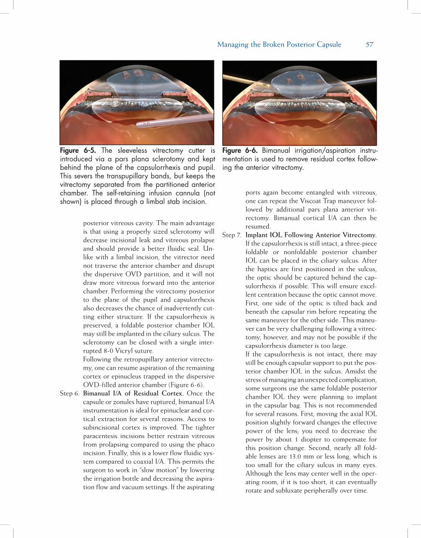
Managing the Broken Posterior Capsule 57
posterior vitreous cavity. The main advantage is that using a properly sized sclerotomy will decrease incisional leak and vitreous prolapse and should provide a better fluidic seal. Un-like with a limbal incision, the vitrector need not traverse the anterior chamber and disrupt the dispersive OVD partition, and it will not draw more vitreous forward into the anterior chamber. Performing the vitrectomy posterior to the plane of the pupil and capsulorrhexis also decreases the chance of inadvertently cut-ting either structure. If the capsulorrhexis is preserved, a foldable posterior chamber IOL may still be implanted in the ciliary sulcus. The sclerotomy can be closed with a single inter-rupted 8-0 Vicryl suture.
Following the retropupillary anterior vitrecto-my, one can resume aspiration of the remaining cortex or epinucleus trapped in the dispersive OVD-filled anterior chamber (Figure 6-6).
Step 6. Bimanual I/A of Residual Cortex. Once the capsule or zonules have ruptured, bimanual I/A instrumentation is ideal for epinuclear and cor-tical extraction for several reasons. Access to subincisional cortex is improved. The tighter paracentesis incisions better restrain vitreous from prolapsing compared to using the phaco incision. Finally, this is a lower flow fluidic sys-tem compared to coaxial I/A. This permits the surgeon to work in “slow motion” by lowering the irrigation bottle and decreasing the aspira-tion flow and vacuum settings. If the aspirating
ports again become entangled with vitreous, one can repeat the Viscoat Trap maneuver fol-lowed by additional pars plana anterior vit-rectomy. Bimanual cortical I/A can then be resumed.
Step 7. Implant IOL Following Anterior Vitrectomy. If the capsulorrhexis is still intact, a three-piece foldable or nonfoldable posterior chamber IOL can be placed in the ciliary sulcus. After the haptics are first positioned in the sulcus, the optic should be captured behind the cap-sulorrhexis if possible. This will ensure excel-lent centration because the optic cannot move. First, one side of the optic is tilted back and beneath the capsular rim before repeating the same maneuver for the other side. This maneu-ver can be very challenging following a vitrec-tomy, however, and may not be possible if the capsulorrhexis diameter is too large.
If the capsulorrhexis is not intact, there may still be enough capsular support to put the pos-terior chamber IOL in the sulcus. Amidst the stress of managing an unexpected complication, some surgeons use the same foldable posterior chamber IOL they were planning to implant in the capsular bag. This is not recommended for several reasons. First, moving the axial IOL position slightly forward changes the effective power of the lens; you need to decrease the power by about 1 diopter to compensate for this position change. Second, nearly all fold-able lenses are 13.0 mm or less long, which is too small for the ciliary sulcus in many eyes. Although the lens may center well in the oper-ating room, if it is too short, it can eventually rotate and subluxate peripherally over time.
Figure 6-5. The sleeveless vitrectomy cutter is introduced via a pars plana sclerotomy and kept behind the plane of the capsulorrhexis and pupil. This severs the transpupillary bands, but keeps the vitrectomy separated from the partitioned anterior chamber. The self-retaining infusion cannula (not shown) is placed through a limbal stab incision.
Figure 6-6. Bimanual irrigation/aspiration instru-mentation is used to remove residual cortex follow-ing the anterior vitrectomy.

58 Chapter 6
For this reason, it is preferable to have longer backup IOLs available, such as a 14.0-mm long three-piece polymethylmethacrylate (PMMA) IOL, or the STAAR Surgical (Monrovia, CA) AQ-2010 foldable three-piece silicone lens with an overall length of 13.5 mm. A single-piece acrylic IOL should never be placed in the sulcus because the overall length is too short and the haptics are not rigid. In addition to poorly centering the lens, the thicker, sharp-edged haptics will rub against the back surface of the iris, causing iris transillumination defects and pigmentary glaucoma.
Although anatomical studies have shown that there is no reliable way to gauge the ciliary sulcus diameter according to external land-marks, it is helpful to measure the white-to-white corneal diameter intraoperatively. If it measures 11.5 mm or less, a standard 13.0-mm long foldable IOL will probably center well in the sulcus. Absent capsulorrhexis capture, a longer IOL should be considered, however, if the sulcus diameter is 12.0 mm or larger. An advanced option is to anchor the sulcus-fixated IOL by suturing one haptic to the iris. A single 10-0 polypropylene McCannel suture around one of the haptics will be enough to keep the lens from rotating or decentering.9 Finally, a properly sized and well-placed anterior cham-ber IOL is always an excellent option if poste-rior chamber IOL support is not ideal.
Final CoMMentsCautious adherence to these principles described
above may help surgeons to reduce the chance of dropping the nucleus following posterior capsular
rupture. However, there is a potentially fine line divid-ing maneuvers that are reasonable and safe from those that are overly aggressive or dangerous. Cataract sur-geons must be honest in assessing their own level of comfort and expertise. Timely surgical management of a dropped nucleus by a vitreoretinal surgeon at a later date is always preferable to overstepping this fine line.10
reFerenCes1. Michelson MA. Use of a Sheets’ glide as a pseudoposterior
capsule in phacoemulsification complicated by posterior cap-sule rupture. Eur J Implant Surg. 1993;570-572.
2. New PAL method may save difficult cataract cases. Ophthal-mology Times. 1994;19:51.
3. Chang DF, Packard RB. Posterior assisted levitation for nu-cleus retrieval using Viscoat after posterior capsule rupture. J Cataract Refract Surg. 2003;29:1860-1865.
4. Chang DF. Managing residual lens material after posterior capsule rupture. Techniques in Ophthalmology. 2003;1(4):201-206.
5. Chang DF. Strategies for managing posterior capsular rup-ture. In: Chang DF, ed. Phaco Chop: Mastering Techniques, Op-timizing Technology, and Avoiding Complications. Thorofare, NJ: SLACK Incorporated; 2004.
6. Burk S, Sugar J, Farber MD. Comparison of the effects of two viscoelastic agents, Healon and Viscoat, on postoperative in-traocular pressure after penetrating keratoplasty. Ophthalmic Surg. 1990;21:821-826.
7. Probst LE, Hakim OJ, Nichols BD. Phacoemulsification with aspirated or retained Viscoat. J Cataract Refract Surg. 1994;20:145-149.
8. Burk SE, Da Mata AP, Snyder ME, et al. Visualizing vitreous using Kenalog suspension. J Cataract Refract Surg. 2003;29:645-651.
9. Chang DF. Siepser slipknot for McCannel iris-suture fixa-tion of subluxated intraocular lenses. J Cataract Refract Surg. 2004;30:1170-1176.
10. Scott IU, Flynn HW, Jr, Smiddy WE, et al. Clinical features and outcomes of pars plana vitrectomy in patients with re-tained lens fragments. Ophthalmology. 2003;110:1567-1572.

59
Managing the SMall PuPilA small pupil increases the likelihood of intraop-
erative complications and was originally considered by Dr. Charles Kelman to be a contraindication to phacoemulsification. In 1985, Dr. Robert Osher pre-sented a series of small pupil cases that were success-fully managed, utilizing a modification of the United Surgical phacoemulsification machine that provided an improvement in fluidics control. Prior to the introduc-tion of this modification, phaco machines had only maximum and minimum settings with a bottle height fixed by a cumbersome rod. Osher introduced a new concept: surgeon-controlled vacuum with continuous irrigation from a bottle of adjustable height, regulated by an automated IV pole. The result of this innovation was a reduction of anterior chamber turbulence and improved stability.
Introducing a technique called slow-motion phaco-emulsification, Osher explained that, by lowering parameters, he was able to perform phacoemulsifica-tion effectively in spite of poorly dilating pupils. He presented a paper entitled “The GASP Technique” (Golly, Another Small Pupil) at the American Intra-Ocular Implant Society meeting and Dr. Kelman was a discussant. Dr. Kelman agreed that by modifying fluidic behavior and reducing surge, the surgeon could
work near the iris with diminished risk of inadvertent iris and capsular damage. This is an approach that has stood the test of time.
Today’s surgeon has a wide range of choices for handling the small pupil. It is the purpose of this chap-ter to review these different options and also discuss the use of reduced phaco parameters in the manage-ment of specific surgical challenges associated with the miotic pupil. The second issue of the 2008 Video Journal of Cataract and Refractive Surgery provides video footage of each of the following categories.
Options for Pharmacologic DilationTraditionally, the use of topical mydriatics in
the form of a sympathomimetic agent combined with a parasympathetic blocker fulfilled the goal of achieving mydriasis. Adding epinephrine to the bal-anced salt solution (BSS) infusion has supplemented and maintained dilation. With the introduction of Ocufen (Allergan, Irvine, CA), it was realized that a nonsteroidal anti-inflammatory drug (NSAID) also contributed to maintenance of dilation by blocking the miotic effect of prostaglandins released when the iris was manipulated.1 A cotton pledget soaked in neosyn-ephrine and placed at the limbus was very effective in achieving maximal dilation but fell out of favor because
Chapter
Management of the Small Pupil
Robert H. Osher, MD, and James M. Osher, MD
7

60 Chapter 7
of systemic concerns. However, IOL Tech, a French company, introduced Mydriasert, a sustained-release product placed in the inferior fornix. Intracameral mydriatics were introduced by Dr. Bjórn Lundberg and Dr. Andes Behndig2 and by Drs. Cionni, Barros, Kaufman, and Osher.3 The instillation of 1% phen-ylephrine directly onto the anterior capsule has been found to be helpful in maintaining pupil size in patients with intraoperative floppy iris syndrome (IFIS) by Drs. Monvikar and Allen4 and Drs. Gurbaxani and Packard.5 Dr. Joel Shugar advocated “Shugarcaine” using 1:1,000 bisulfite-free epinephrine that is mixed in a 1:3 dilution with three parts BSS+ and one part nonpreserved lidocaine 4%. Approximately 1 mL of this mixture is slowly injected into the anterior cham-ber before instillation of the ophthalmic viscosurgical device (OVD).6
Viscomydriasis With Healon 5Pupillary dilation can be achieved by the injection
of an OVD (viscomydriasis). Healon 5 (AMO, Santa Ana, CA), a high molecular weight sodium hyaluronate OVD, is uniquely capable of dilating and maintaining a wide pupil.7 By mechanically moving iris tissue toward the angle, Healon 5 is effective in expanding the pupil (Figure 7-1). Moreover, Healon 5 behaves as a highly retentive, semi-solid material that bows the iris poste-riorly, resulting in a deeper chamber with additional dilation. Some pupils will enlarge dramatically with Healon 5, while others will dilate less. In virtually all patients, however, Healon 5 produces some useful viscomydriasis. While it is easy to obtain initial visco-mydriasis, it is often necessary to reinject Healon 5 in order to maintain the effect. This is because either the OVD is aspirated or it escapes through the incision,
allowing the pupil to narrow. In order to use Healon 5 most effectively as a viscomydriatic, it is important to understand how to keep the Healon 5 in the anterior chamber.
Healon 5 behaves as a dispersive OVD when the vacuum is less than about 200 mmHg and the aspira-tion rate is about 25 cc/min or less. If the vacuum or aspiration rate exceeds these levels, the material behaves in a cohesive manner. This unique variable vis-coelastic behavior allows the surgeon to keep Healon 5 in the anterior chamber during the phacoemulsifica-tion if vacuum and aspiration rates are maintained at low levels, and then remove the OVD material readily at the conclusion of the procedure, using higher vacu-um and aspiration settings. Since ultrasonic energy is capable of shattering the tightly packed, long-chained molecules, it is best to avoid anterior chamber emul-sification as fractured Healon 5 is less likely to resist aspiration forces. Moreover, if a high bottle height cre-ates a high pressure in the eye, there is a greater likeli-hood that the Healon 5 will be “forced” either into the aspiration port or out through the incision, especially when the latter is poorly constructed or distorted. (See below for a step-by-step explanation of the use of Healon 5 in IFIS.)
Stretching the PupilCutting or stretching the pupillary sphincter is
another method of obtaining a larger pupil during surgery. The use of scissors to create multiple sphinc-terotomies was popular during the 1990s before Dr. Luther Fry popularized the pupil stretch technique.8 Pupil stretching is accomplished with two blunt instru-ments (eg, hooks, collar buttons, retractors, etc). Under the protection of an OVD, the hooks are introduced
Figure 7-1. Viscomydriasis occurs as Healon 5 is injected.
A B

Management of the Small Pupil 61
and placed in the same meridian 180 degrees away from one another. The iris is then stretched with each instrument simultaneously toward the angle, momen-tarily held, and then released (Figure 7-2). A second stretch can be performed 90 degrees away from the first if the surgeon desires. After pupil stretching, when OVD is reinjected, an enlargement of the pupil usually occurs. While small sphincter ruptures are visible at the slit lamp following surgery, the pupil generally retains a physiologic shape and functions normally.
Peripupillary MembranectomyAnother technique involving the pupillary sphinc-
ter is peripupillary membranectomy, which Osher described in the early 1980s.9 In cases of uveitis or chronic pilocarpine usage, the pupil is bound down by synechiae, which prohibit the pupil from dilating. A string-like fibrotic membrane at the border of the pupil can often be stripped, which serves to release the pupil (Figure 7-3).
Iris HooksIris retractors are another option for achieving
mechanical dilation. Prior to the introduction of micro-scopic hooks, surgeons occasionally used a retraction suture or deliberately prolapsed the iris into an incision to achieve a dilatory effect. Later, metal, fine wire, and prolene retractors were introduced by Drs. Mackool,10 Engels,11 and deJuan,12 respectively. Iris hooks may be disposable or reusable and may be anchored by adjust-able corks, sliding tabs, or weights. The technique for inserting the iris hooks requires a carefully thought-out plan since tenting the iris toward the cornea should be avoided (Figure 7-4). In cases with a shallow chamber, an instrument introduced through a remote incision may help to usher the hook into position. The surgeon may vary the number of iris hooks as well as the incisions. A recent variant has been introduced by Drs. Oetting and Omphrey. These authors described the placement of a hook below the primary cataract incision, which creates a diamond-shaped pupil for optimal visualization and manipulation of the ultra-sound and irrigation and aspiration (I/A) tips.13 While tiny sphincter ruptures can be observed at the slit lamp following surgery, the pupil usually regains normal size and function. Although some effort and time is
Figure 7-2. Fry pupil stretch technique.
Figure 7-3. Osher peripupillary membranectomy.
A
B
C

62 Chapter 7
required to place iris hooks, the hooks are very effec-tive in maintaining an enlarged and stable pupil during phacoemulsification.
Surgical Instruments and Devices for Dilating the Pupil
A number of devices have been developed that will facilitate pupillary dilation. The first such device was the Beehler dilator, manufactured by Moria (Doylestown, PA), which was composed of three prongs that would mechanically stretch the pupil. The Graether silicone pupil dilator14 and the Siepser hydrogel tire15 were designed to mechanically open and maintain the larger pupil. Morcher introduced a plastic incomplete circle (300 degrees) that would allow the surgeon to place this device at the pupil-lary border and the fixed diameter would mechani-cally enlarge the pupil.16 The Milverton Perfect Pupil, manufactured by Becton Dickinson (Franklin Lakes, NJ), was a similar design with a small handle.17 The most recent advance is an injectable ring developed by Dr. Boris Malyugin of Moscow and distributed by MST (Redmond, WA).18 The closed ring is injected through a small incision and its four scrolls capture and retract the pupil border, maintaining an adequate opening until the device is removed at the conclusion of the procedure (Figure 7-5).
Managing Challenging CliniCal SituationS
Intraoperative Floppy Iris Syndrome Prior to the excellent detective work of Dr. David
Chang and Dr. John Campbell linking IFIS with
tamsulosin use,19 surgeons were often mystified by a perplexing group of patients whose pupils did not dilate well and who demonstrated a progressive miosis during surgery. This group of patients also routinely demonstrated a reduction of the iris tone with intra-operative billowing and iris prolapse. Thanks to the efforts of Drs. Chang and Campbell, it is understood now that tamsulosin is a primary cause of iris dysfunc-tion during cataract surgery. IFIS is among the most challenging situations encountered by the cataract sur-geon. Healon 5, which can be used to maintain pupil dilation in patients with IFIS, is a very useful tool in the management of these cases.20
Management of Intraoperative Floppy Iris Syndrome, Utilizing Healon 5: A Step-by-Step ApproachStep 1. Dilate the Pupil and Stabilize the Iris. First,
with the cannula opening well beyond the incision, inject Healon 5 into the anterior chamber to create viscomydriasis. Simultane-ously, the Healon 5 will also displace the iris
Figure 7-4. Pupil enlarged with iris hooks.
Figure 7-5. Mechanical dilation with the Malyugin ring.
A
B
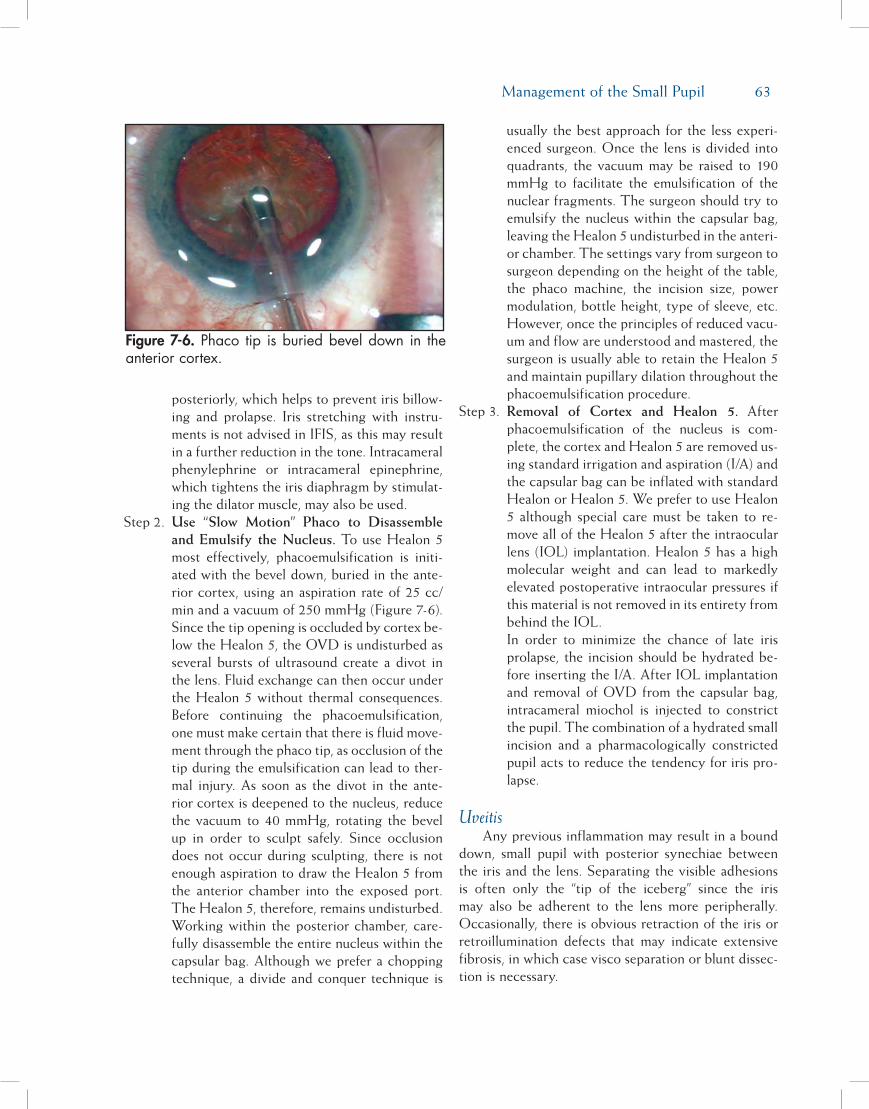
Management of the Small Pupil 63
posteriorly, which helps to prevent iris billow-ing and prolapse. Iris stretching with instru-ments is not advised in IFIS, as this may result in a further reduction in the tone. Intracameral phenylephrine or intracameral epinephrine, which tightens the iris diaphragm by stimulat-ing the dilator muscle, may also be used.
Step 2. Use “Slow Motion” Phaco to Disassemble and Emulsify the Nucleus. To use Healon 5 most effectively, phacoemulsification is initi-ated with the bevel down, buried in the ante-rior cortex, using an aspiration rate of 25 cc/min and a vacuum of 250 mmHg (Figure 7-6). Since the tip opening is occluded by cortex be-low the Healon 5, the OVD is undisturbed as several bursts of ultrasound create a divot in the lens. Fluid exchange can then occur under the Healon 5 without thermal consequences. Before continuing the phacoemulsification, one must make certain that there is fluid move-ment through the phaco tip, as occlusion of the tip during the emulsification can lead to ther-mal injury. As soon as the divot in the ante-rior cortex is deepened to the nucleus, reduce the vacuum to 40 mmHg, rotating the bevel up in order to sculpt safely. Since occlusion does not occur during sculpting, there is not enough aspiration to draw the Healon 5 from the anterior chamber into the exposed port. The Healon 5, therefore, remains undisturbed. Working within the posterior chamber, care-fully disassemble the entire nucleus within the capsular bag. Although we prefer a chopping technique, a divide and conquer technique is
usually the best approach for the less experi-enced surgeon. Once the lens is divided into quadrants, the vacuum may be raised to 190 mmHg to facilitate the emulsification of the nuclear fragments. The surgeon should try to emulsify the nucleus within the capsular bag, leaving the Healon 5 undisturbed in the anteri-or chamber. The settings vary from surgeon to surgeon depending on the height of the table, the phaco machine, the incision size, power modulation, bottle height, type of sleeve, etc. However, once the principles of reduced vacu-um and flow are understood and mastered, the surgeon is usually able to retain the Healon 5 and maintain pupillary dilation throughout the phacoemulsification procedure.
Step 3. Removal of Cortex and Healon 5. After phacoemulsification of the nucleus is com-plete, the cortex and Healon 5 are removed us-ing standard irrigation and aspiration (I/A) and the capsular bag can be inflated with standard Healon or Healon 5. We prefer to use Healon 5 although special care must be taken to re-move all of the Healon 5 after the intraocular lens (IOL) implantation. Healon 5 has a high molecular weight and can lead to markedly elevated postoperative intraocular pressures if this material is not removed in its entirety from behind the IOL.
In order to minimize the chance of late iris prolapse, the incision should be hydrated be-fore inserting the I/A. After IOL implantation and removal of OVD from the capsular bag, intracameral miochol is injected to constrict the pupil. The combination of a hydrated small incision and a pharmacologically constricted pupil acts to reduce the tendency for iris pro-lapse.
UveitisAny previous inflammation may result in a bound
down, small pupil with posterior synechiae between the iris and the lens. Separating the visible adhesions is often only the “tip of the iceberg” since the iris may also be adherent to the lens more peripherally. Occasionally, there is obvious retraction of the iris or retroillumination defects that may indicate extensive fibrosis, in which case visco separation or blunt dissec-tion is necessary.
Figure 7-6. Phaco tip is buried bevel down in the anterior cortex.

64 Chapter 7
Management of Iris Synechiae: A Step-by-Step ApproachStep 1. Analyze the Extent of Pupillary Fibrosis and
Lens to Iris Synechiae. Place Healon 5 in the anterior chamber to provide viscomydriasis as described above. Look for evidence of re-stricted dilation of the pupil and locate areas of adhesions of the iris to the lens capsule.
Step 2. Use Mechanical Measures to Open the Pu-pil, if Necessary. If there is evidence of pupil-lary fibrosis which prevents the dilation of the pupil with Healon 5, the surgeon may attempt to grasp the pupil margin with a micro-forceps and then with light traction, determine wheth-er a peripupillary membrane is present. On oc-casion this membrane can simply be removed, freeing the pupil. If this is unsuccessful, the pu-pil should be stretched mechanically. Healon 5 should be utilized again in an effort to dilate the pupil. If an adequate pupil size cannot be obtained after these maneuvers, iris hooks may be employed as described above.
Step 3. Use Healon 5 and Blunt Dissection, if Nec-essary, to Lyse Iris to Lens Synechiae. Lys-ing the synechiae at the pupillary border fre-quently can be accomplished with the Healon 5 cannula. More extensive fibrosis may require visco separation or blunt dissection. Subinci-sional adhesions may be separated with either a “J-shaped” cannula through the primary in-cision, a sweeping maneuver with the Healon 5 cannula from the side port, or an iridotomy may be performed to allow the introduction of either a spatula or the OVD cannula for vis-codissection.
Whenever there is evidence of old intraocu-lar inflammation, especially when the iris has undergone significant surgical manipulation, periocular steroids and NSAIDs, as well as topical steroids, should be considered to pre-vent excessive postoperative inflammation and synechial recurrence.
PseudoexfoliationIn pseudoexfoliation, careful preoperative bio-
microscopy reveals the powdery white material that may or may not be present in the classic tri-zonal distribution. A weakness of zonules is associated with pseudoexfoliation, but in most instances, it is the small pupil that creates the greatest potential for intraopera-tive complications. Suboptimal dilation associated with
pseudoexfoliation is fortunately not accompanied by either iris atonicity or iris synechiae, and the Fry pupil stretch technique is usually very effective in creating pupillary dilation.
Management of the Miotic Pupil in Pseudoexfoliation: A Step-by-Step ApproachStep 1. Dilate the Pupil Using Pupillary Stretching.
After filling the chamber with Healon 5, two dull Y-hooks or collar button hooks are intro-duced, one through the main incision and the other through a side-port incision. Alternative-ly, two side-port incisions may be utilized. The tips of the hooks are advanced until the pupil margin is engaged in the same meridian but on opposite sides of the pupil. The distal hook is advanced while the proximal hook is retracted. The pupil is stretched and held in a stretched position for a moment. Care should be taken not to damage the anterior lens capsule. The hooks can be repositioned in a meridian 90 de-grees away for an additional stretch if desired.
Step 2. Use “Slow-Motion” Phacoemulsification to Disassemble and Emulsify the Nucleus. Once the pupil has been stretched, the injection of Healon 5 will further widen the pupil. Slow-motion phacoemulsification with lowered parameters offers the best strategy to retain the Healon 5 and maintain dilation in cases of pseudoexfoliation. The technique for using Healon 5 with slow-motion phacoemulsifica-tion is the same as with IFIS. (See the above description of the use of slow-motion phaco-emulsification, under the discussion of IFIS.) Should the surgeon encounter any signs of sig-nificant zonular weakness, he or she should be familiar with the use of iris/capsular retractors to stabilize the lens bag as well as a capsular tension ring (see Chapter 14, Capsular Tension Rings), which has greatly improved the man-agement of this serious complication.
White or Brunescent CataractThe mature cataract is often associated with a
poorly dilating pupil. Even when the pupil dilates to 5 mm, the presence of a white or an extremely brunes-cent cataract compromises visualization of the anterior capsule. This reduced visualization makes the creation of a continuous curvilinear capsulotomy very difficult. With mature lenses, visualization of the anterior cap-sule is greatly facilitated by the use of capsule dyes,

Management of the Small Pupil 65
such as indocyanine green, introduced by Horiguchi et al,21 and trypan blue, first described by Melles et al.22
Staining the anterior capsule with these dyes can be accomplished by a number of different techniques, but we prefer a three-step method utilizing Healon 5.23
Capsule Staining, Utilizing Healon 5: A Step-by-Step ApproachStep 1. Place Healon 5 over the Anterior Capsule.
Healon 5 is injected into the anterior cham-ber, being careful not to overfill it. Healon 5, which is highly retentive under conditions of low flow, provides a very stable chamber for intraocular manipulation.
Step 2. Create a Space Between Healon 5 and the Anterior Capsule. Inject BSS directly onto the anterior capsule, elevating the Healon 5 into the corneal dome while creating a thin layer of fluid directly over the anterior capsule.
Step 3. Inject Capsular Staining Dye Into the Supra-capsular Space. Trypan blue is then placed into the thin BSS-filled space. This results in an even stain of the anterior capsule without creating an “ink blot” in the anterior chamber or forcing dye under pressure through the zon-ules into the vitreous cavity. The Osher dye cannula (Storz [Bausch & Lomb, San Dimas, CA] and Crestpoint Management [St Louis, MO]) has the port on the posterior surface of the cannula that allows the dye to be delivered precisely onto the anterior capsular surface. It may be necessary to inject additional BSS or Healon 5 to gain optimal visualization before proceeding with the capsulorrhexis.
Small Pupil Associated With Iridodialysis Rarely, the anterior segment surgeon will encounter
a traumatic cataract associated with extensive iris disin-sertion. Depending upon the extent of the damage, the pupil may appear miotic and eccentric. The iris must be reattached to the sclera by a series of nonabsorbable horizontal mattress sutures. Following the repair of the iridodialysis, the use of iris hooks or pupil-expanding devices may be helpful if pharmacologic dilation still fails to achieve an appropriate pupil size.
SuMMaryDr. Charles Kelman, the father of phacoemulsi-
fication, alerted his disciples to the perils of operat-ing upon the cataract patient with a small pupil. For
many years, the small pupil was one of Dr. Kelman’s contraindications to phacoemulsification. Fortunately, advances in machine technology, viscosurgery, surgi-cal techniques, and devices for mechanical dilation have made operating within the small pupil far more safe and compatible with an excellent visual outcome.
referenCeS1. Duffin RM, Camras CB, Gardner SK, Pettit TH. Inhibitors of
surgically induced miosis. Ophthalmology. 1982;89:966-979.2. Lundberg B, Behndig A. Intracameral mydriatics in phaco-
emulsification cataract surgery. J Cataract Refract Surg. 2003;29:2366-2371.
3. Cionni RJ, Barros MG, Kaufman AH, Osher R. Cataract sur-gery without preoperative eyedrops. J Cataract Refract Surg. 2003;29:2281-2283.
4. Monvikar S, Allen D. Cataract surgery management in pa-tients taking tamsulosin staged approach. J Cataract Refract Surg. 2006;32:1611-1614.
5. Gurbaxani A, Packard R. Intracameral phenylephrine to pre-vent floppy iris syndrome during cataract surgery in patients on tamsulosin. Eye. 2007;21:331-332.
6. Shugar J. Use of epinephrine for IFIS prophylaxis. J Cataract Refract Surg. 2006;32:1074-1075.
7. Osher R. Viscomydriasis. Video J Cataract Refract Surg. 2002;XVIII(2).
8. Fry L. Pupil stretching. Video J Cataract Refract Surg. 1995;XI(1).
9. Osher R. Peripupillary membranectomy. Video J Cataract Re-fract Surg. 1991;VII(3).
10. Mackool R. Small pupil enlargement during cataract extrac-tion: a new method. J Cataract Refract Surg. 1992;18:523-526.
11. Engels T. Peripupillary membranectomy. Wire retractor. Vid-eo J Cataract Refract Surg. 1995;XI(1).
12. deJuan E Jr, Hickingbotham D. Flexible iris retractor (letter). Am J Ophthalmol. 1991;111:776-777.
13. Oetting TA, Omphrey LC. Modified technique using flex-ible iris retractors in clear corneal surgery. J Cataract Refract Surg. 2002;28:596-598.
14. Graether J. Silicone expander. Video J Cataract Refract Surg. 1995;XI(1).
15. Siepser S. Expansile hydrogel ring. Video J Cataract Refract Surg. 1995;XI(1).
16. Akman A, Yilmaz G, Oto S, et al. Comparison of various methods of phacoemulsification in eyes with a small pupil sec-ondary to pseudoexfoliation. Ophthalmology. 2004;111:1693-1698.
17. Auffarth G, Reuland A, Heger T, et al. Cataract surgery in eyes with iridoschisis using the Perfect Pupil iris extension system. J Cataract Refract Surg. 2005;31:1877-1880.
18. Malyugin B. Russian solution to small pupil phaco and the tamsulosin floppy iris syndrome. Video J Cataract Refract Surg. 2007;XXIII(1).
19. Chang DF, Campbell JR. Intraoperative floppy iris syn-drome associated with tamsulosin. J Cataract Refract Surg. 2005;31:663-673.
20. Osher R. Healon 5 in IFIS. Video J Cataract Refract Surg. 2005;XXI(2).
21. Horiguchi M, Miyake K, Ohta I, et al. Staining of the lens

66 Chapter 7
capsule for circular continuous capsulorrhexis in eyes with white cataract. Arch Ophthalmol. 1998;116:535-537.
22. Melles G, deWaard P, Pameyer J, et al. Trypan blue capsule staining to visualize the capsulorrhexis in cataract surgery. J
Cataract Refract Surg. 1999;25:7-9.23. Marques DM, Marques FF, Osher RH. Three-step technique
for staining the anterior lens capsule with indocyanine green or trypan blue. J Cataract Refract Surg. 2004;30:13-16.
67
Introduced by Dr. Charles Kelman in 1962, phaco-emulsification machines have undergone constant improvement, ever increasing both their complex-ity and safety. There is one principle, however, that remains unchanged. All phaco machines consist of a computer to generate electrical signals and a trans-ducer to turn these electronic signals into mechanical energy. The energy thus produced is passed through a hollow needle and is controlled within the eye to overcome the inertia of the lens and emulsify it. Once turned into emulsate, fluidic systems remove the emul-sate, replacing it with balanced salt solution (BSS).
Power GenerationPower is created by an interaction between fre-
quency and stroke length. Frequency is defined as the speed of the needle
movement. The manufacturer of the machine deter-mines it. Presently, most machines operate at a fre-quency between 27,000 cycles per second (Hz) to 50,000 cycles per second. This frequency range is efficient for nuclear emulsification. Lower frequencies become less efficient and higher frequencies create excess heat.
Stroke length is defined as the length of the needle movement. This length is generally 2 to 6 mils (thou-
sandths of an inch). Most machines operate in the 2 to 4 mil range. One mil is 25 microns. Therefore, most phaco needles travel a distance of 50 to 100 microns. The longer the stroke length, the greater the physical impact on the nucleus and the greater the generation of cavitation energy. Longer stroke lengths, like higher frequencies, however, tend to generate extra heat.
Stroke length is determined by foot pedal excur-sion in position 3 during linear control of phaco. As the foot pedal is depressed, the stroke length and therefore the power increase to the preset maximum. New foot pedals allow the surgeon to control the throw length in each major division, increasing the capability of the surgeon to manage control of both the fluidic and ultrasonic components of phaco.
TuningThe central processing unit (CPU) of modern
phaco machines recognizes when the phaco needle passes into different intraocular media. For example, the resistance of the aqueous is less than the resistance of the cortex, which in turn, is less than the resistance of the nucleus. As the resistance to the phaco tip var-ies to maintain maximum efficiency dependent on the machine, small alterations in frequency or stroke length are created by the tuning circuitry in the CPU.
Chapter
The Phaco MachineUnderstanding the Equipment to Take
Advantage of Contemporary Phaco Techniques
William J. Fishkind, MD, FACS
8
68 Chapter 8
This is important to minimize the excessive generation of ultrasonic energy, which is harmful to the intraocu-lar contents. The surgeon will subjectively determine good tuning circuitry by a sense of smoothness and power.
Phaco EnergyThe actual tangible forces that emulsify the nucle-
us are thought to be a blend of the “jackhammer” effect and cavitational energy.1 The jackhammer effect is the physical striking of the needle against the nucleus. The cavitation effect is more convoluted. Recent studies indicate that there are two kinds of cavitational energy. One is transient cavitation and the other is sustained cavitation.
Transient CavitationThe phaco needle, moving through a liquid medi-
um at ultrasonic speeds, gives rise to intense zones of high and low pressure. Low pressure, created with backward movement of the tip, pulls dissolved gases out of solution, thus producing micro bubbles. Forward tip movement then creates an equally intense zone of high pressure. This initiates compression of the micro bubbles until they implode. At the moment of implosion, the bubbles create a temperature of 7204˚C degrees and a shock wave of 5,171,100 mbar. Of the micro bubbles created, 75% implode, amassing to cre-ate a powerful shock wave radiating from the phaco tip in the direction of the bevel with annular spread. However, 25% of the bubbles are too large to implode. These micro bubbles are swept up in the shock wave and radiate with it. Transient cavitation is a violent event. The energy created by transient cavitation exists for no more than 4 milliseconds and is present only in the immediate vicinity of the phaco tip and within its lumen. It is this form of cavitation that is thought to generate the energy responsible for emulsification of cataractous material. Additionally, transient cavitation is instrumental in clearing nuclear fragments within the phaco needle, preventing repetitive needle clogging.
The transient cavitational energy can be directed in any desired direction. The angle of the bevel of the phaco needle governs the direction of the generation of the shock wave and micro bubbles.
I have developed a method of visualization of these forces called “enhanced cavitation.” Using this process, it can be seen that with a 45-degree tip, the cavitation wave is generated at 45 degrees from the tip. Similarly, a 30-degree tip generates cavitation at a 30-degree
angle from the bevel, and a 15-degree tip 15 degrees from the bevel. A 0-degree tip creates the cavitation wave directly in front of the tip and the focal point is 0.5 mm from the tip. The Kelman tip has a broad band of powerful cavitation that radiates from the area of the angle in the shaft. A weak area of cavitation is devel-oped from the bevel but is inconsequential.
Taking into consideration analysis of enhanced cavitation, it can be concluded that phacoemulsifica-tion is most efficient when both the jackhammer effect and cavitation energy are combined. To accomplish this, the bevel of the needle should be turned toward the nucleus or nuclear fragment. This simple maneuver will cause the broad bevel of the needle to strike the nucleus. This will enhance the physical force of the needle striking the nucleus. In addition, the cavitation force is then concentrated into the nucleus rather than away from it. Finally, in this configuration, the vacuum force can be maximally exploited as occlusion is encour-aged. This causes energy to emulsify the nucleus and be absorbed by it. A 0-degree tip automatically focuses both the jackhammer and cavitational energy directly in front of it. When the bevel is turned away from the nucleus, the cavitational energy is directed up and away from the nucleus toward the iris and endothelium.
Sustained CavitationIf phaco is energized beyond 4 milliseconds, tran-
sient cavitation with generation of micro bubbles and shock waves ends. The bubbles then begin to vibrate without implosion. No shock wave is generated. Therefore, there is no emulsification energy produced. Sustained cavitation is ineffective for emulsification.
Water bath, hydrophonic studies indicate that transient cavitation is significantly more powerful than sustained cavitation. With this information in mind, it would appear that continuous phaco is best used to emulsify the intact nucleus, held in place by the capsular bag, during the sculpting phase of divide and conquer or stop and chop. Jackhammer energy is most important for emulsification in this setting.
Transient cavitation is maximized during micro-pulse phaco. This is best used during phaco of the nuclear fragments in the later phase of the above two procedures or during phaco chop procedures.
Modification of Phaco Power intensity
Application of the minimal amount of phaco power intensity necessary for adequate emulsification of the
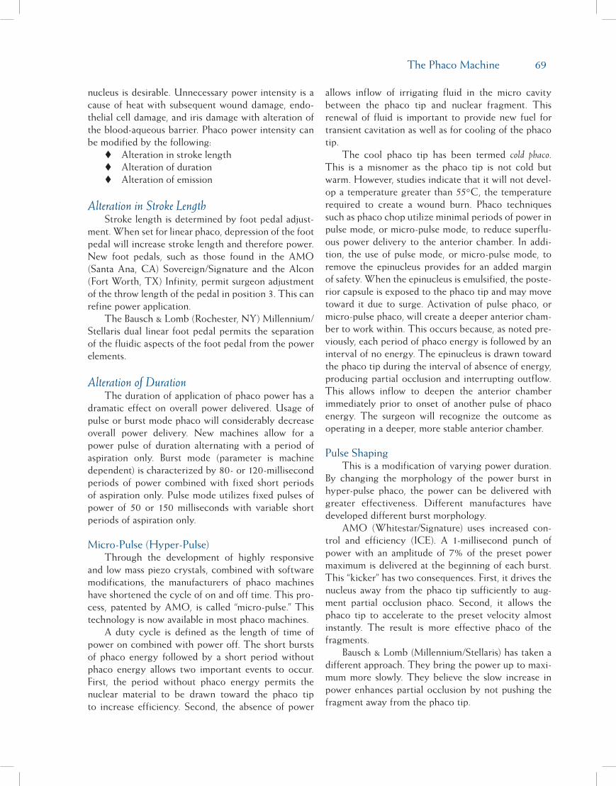
The Phaco Machine 69
nucleus is desirable. Unnecessary power intensity is a cause of heat with subsequent wound damage, endo-thelial cell damage, and iris damage with alteration of the blood-aqueous barrier. Phaco power intensity can be modified by the following: Alteration in stroke length Alteration of duration Alteration of emission
Alteration in Stroke LengthStroke length is determined by foot pedal adjust-
ment. When set for linear phaco, depression of the foot pedal will increase stroke length and therefore power. New foot pedals, such as those found in the AMO (Santa Ana, CA) Sovereign/Signature and the Alcon (Fort Worth, TX) Infinity, permit surgeon adjustment of the throw length of the pedal in position 3. This can refine power application.
The Bausch & Lomb (Rochester, NY) Millennium/Stellaris dual linear foot pedal permits the separation of the fluidic aspects of the foot pedal from the power elements.
Alteration of DurationThe duration of application of phaco power has a
dramatic effect on overall power delivered. Usage of pulse or burst mode phaco will considerably decrease overall power delivery. New machines allow for a power pulse of duration alternating with a period of aspiration only. Burst mode (parameter is machine dependent) is characterized by 80- or 120-millisecond periods of power combined with fixed short periods of aspiration only. Pulse mode utilizes fixed pulses of power of 50 or 150 milliseconds with variable short periods of aspiration only.
Micro-Pulse (Hyper-Pulse)Through the development of highly responsive
and low mass piezo crystals, combined with software modifications, the manufacturers of phaco machines have shortened the cycle of on and off time. This pro-cess, patented by AMO, is called “micro-pulse.” This technology is now available in most phaco machines.
A duty cycle is defined as the length of time of power on combined with power off. The short bursts of phaco energy followed by a short period without phaco energy allows two important events to occur. First, the period without phaco energy permits the nuclear material to be drawn toward the phaco tip to increase efficiency. Second, the absence of power
allows inflow of irrigating fluid in the micro cavity between the phaco tip and nuclear fragment. This renewal of fluid is important to provide new fuel for transient cavitation as well as for cooling of the phaco tip.
The cool phaco tip has been termed cold phaco. This is a misnomer as the phaco tip is not cold but warm. However, studies indicate that it will not devel-op a temperature greater than 55°C, the temperature required to create a wound burn. Phaco techniques such as phaco chop utilize minimal periods of power in pulse mode, or micro-pulse mode, to reduce superflu-ous power delivery to the anterior chamber. In addi-tion, the use of pulse mode, or micro-pulse mode, to remove the epinucleus provides for an added margin of safety. When the epinucleus is emulsified, the poste-rior capsule is exposed to the phaco tip and may move toward it due to surge. Activation of pulse phaco, or micro-pulse phaco, will create a deeper anterior cham-ber to work within. This occurs because, as noted pre-viously, each period of phaco energy is followed by an interval of no energy. The epinucleus is drawn toward the phaco tip during the interval of absence of energy, producing partial occlusion and interrupting outflow. This allows inflow to deepen the anterior chamber immediately prior to onset of another pulse of phaco energy. The surgeon will recognize the outcome as operating in a deeper, more stable anterior chamber.
Pulse ShapingThis is a modification of varying power duration.
By changing the morphology of the power burst in hyper-pulse phaco, the power can be delivered with greater effectiveness. Different manufactures have developed different burst morphology.
AMO (Whitestar/Signature) uses increased con-trol and efficiency (ICE). A 1-millisecond punch of power with an amplitude of 7% of the preset power maximum is delivered at the beginning of each burst. This “kicker” has two consequences. First, it drives the nucleus away from the phaco tip sufficiently to aug-ment partial occlusion phaco. Second, it allows the phaco tip to accelerate to the preset velocity almost instantly. The result is more effective phaco of the fragments.
Bausch & Lomb (Millennium/Stellaris) has taken a different approach. They bring the power up to maxi-mum more slowly. They believe the slow increase in power enhances partial occlusion by not pushing the fragment away from the phaco tip.

70 Chapter 8
Alteration of EmissionThe emission of phaco energy is modified by tip
selection. Phaco tips can be modified to accentuate the following: Power Flow A combination of both
Power intensity is modified by altering bevel tip angle. Noted previously, the bevel of the phaco tip will focus power in the direction of the bevel. The Kelman tip will produce broad powerful cavitation directed away from the angle in the shaft. This tip is excellent for the hardest of nuclei. New flare and cobra tips direct cavitation into the opening of the bevel of the tip. Thus random emission of phaco energy is mini-mized. Designer tips such as the “Flathead” designed by Dr. Barry Seibel and power wedges designed by Mr. Douglas Mastel modify the direction and focus delivery of phaco energy intensity.
Power intensity and flow are modified by utilizing a 0-degree tip. This tip will focus power directly ahead of the tip and enhance occlusion due to the smaller surface area of its orifice. Small diameter tips, such as 21-gauge tips or flair tips, change fluid flow rates. Although they do not actually change power intensity, they appear to have this effect, as the nucleus must be emulsified into smaller pieces for removal through the smaller diameter tip.
The Alcon aspiration bypass system (ABS) tip modification is available with a 0-degree tip, a Kelman tip, or a flare tip. The flare is a modification of power intensity and the ABS a flow modification. In the ABS system, a 0.175-mm hole in the shaft permits a variable flow of fluid into the needle, even during occlusion. Therefore, occlusion is never allowed to occur. This flow adjustment serves to minimize surge.
Finally, flow can be modified by utilizing one of the microseal tips. These tips have a flexible outer sleeve to seal the phaco incision. They also have a rigid inner sleeve or a ribbed shaft configuration to protect cool-ing irrigant inflow. Thus a tight seal allows low flow phaco without danger of wound burns. Phaco power intensity is the energy that emulsifies the lens nucleus. The phaco tip must operate in a cool environment and with adequate space to isolate its actions from delicate intraocular structures. This portion of the action of the machine is dependent upon its fluidics.
fluidicsThe fluidics of all machines is fundamentally a
balance of fluid inflow and fluid outflow. Inflow is
determined by bottle height above the eye of the patient and irrigation tubing diameter. It is important to recognize that with recent acceptance of temporal surgical approaches and modifications of the surgical table, the eye of the patient may be physically higher than in the past. This requires that the irrigation bottle be adequately elevated. A shallow, unstable anterior chamber will otherwise result.
Outflow is determined by the sleeve-incision relationship, as well as the paracentesis size, aspira-tion rate, and vacuum level commanded. The incision length selected should create a snug fit with the phaco tip selected. This will result in minimal uncontrolled wound outflow with resultant increased anterior cham-ber stability.
Aspiration rate, or flow, is defined as the flow of fluid, measured in cc/min, through the tubing. With a peristaltic pump, it is determined by the speed of the pump. Flow determines how well particulate mat-ter is attracted to the phaco tip. Aspiration level or vacuum is a level measured in mmHg. It is defined as the magnitude of negative pressure created in the tub-ing. Vacuum is the determinant of how well particulate material will be held to the tip, once occluded on the phaco tip.
VacuuM sourcesThere are three categories of vacuum sources or
pumps. These are flow pumps, vacuum pumps, and hybrid pumps. The primary example of the flow pump type is the peristaltic pump. These pumps allow for independent control of both aspiration rate (flow) and aspiration level (vacuum). The primary example of the vacuum pump is the Venturi pump. This pump type allows direct control of only vacuum level. Flow is dependent upon vacuum level setting. Additional example types are the rotary vane and diaphragmatic pumps. The primary example of the hybrid pump is the AMO Sovereign/Signature peristaltic pump or the Bausch & Lomb Concentrix pump. These pumps are interesting as they are able to act like either a vacuum or flow pump depending on programming. They are generally controlled by digital inputs creating incred-ible flexibility and responsiveness.
The challenge to the surgeon is to balance the effect of phaco power intensity, which tends to push nuclear fragments away from the phaco tip, with the effect of flow, which attracts fragments toward the phaco tip, and vacuum, which holds the fragments on the phaco tip. Generally, low flow slows down intra-ocular events, and high vacuum speeds them up. Low

The Phaco Machine 71
or zero vacuum is helpful during sculpting of hard or large nucleus where the high power intensity of the tip may be applied near the iris or anterior capsule. Zero vacuum will prevent inadvertent aspiration of the iris or capsule, avoiding significant morbidity.
surGeA fundamental limiting factor in the selection
of high levels of vacuum or flow is the development of surge. When the phaco tip is occluded, flow is interrupted and vacuum builds to its preset level. Emulsification of the occluding fragment then clears the occlusion. Flow instantaneously begins at the pre-set level in the presence of the high vacuum level. In addition, if the aspiration line tubing is not reinforced to prevent collapse (a function of tubing compliance), the tubing will have constricted during the occlusion. It then expands on occlusion break. This expansion is an additional source of vacuum production. These factors trigger a rush of fluid from the anterior seg-ment into the phaco tip. The fluid in the anterior chamber may not be replaced rapidly enough by infu-sion to prevent shallowing of the anterior chamber. Therefore, with sudden volume reduction in the ante-rior chamber there is succeeding rapid anterior move-ment of the posterior capsule. This abrupt forceful stretching of the bag around nuclear fragments (espe-cially if the fragment is hard with jagged edges) may be a cause of capsular tears. In addition, the posterior capsule can be literally sucked into the phaco tip, tear-ing it. The magnitude of the surge is contingent on the duration of occlusion and the pre-surge settings of flow and vacuum.
Classically selecting lower levels of flow and vac-uum control surge. The phaco machine manufacturers help to decrease surge by providing noncompliant aspiration tubing that will not constrict in the pres-ence of high levels of vacuum. More important are the following noteworthy new technologies: CASE: AMO Sovereign/Signature—Micro-
processors sample vacuum and flow param-eters 50 times a second, creating a “virtual” anterior chamber model. At the moment of occlusion, the computer senses the decrease in flow and instantaneously slows the pump to stop surge production. The Alcon Infinity works in a similar manner.
Dual Linear: Bausch & Lomb Millennium/Stel-laris—The dual linear foot pedal can be pro-grammed to separate both the flow and vacu-
um from power. In this way, flow or vacuum can be lowered before beginning the emulsi-fication of an occluding fragment. The emul-sification therefore occurs in the presence of a lower vacuum or flow so that surge is mini-mized.
ABS: Alcon Infinity/Legacy—The ABS tips have 0.175-mm holes drilled in the shaft of the needle. During occlusion, the hole provides for a constant alternate fluid flow. This will cause dampening of the surge on occlusion break.
Nonlongitudinal Phaco: Modification of Fluid Control by Power Modulations
Three significant, trend-setting technologies have revolutionized the way power is modulated. When employing these power modulations, the duration of power operation and the motion of needle move-ment are significant on their effect on fluid flow and occlusion. These modulations have an effect on the fluidic balance during phaco, which is as important to chamber maintenance and ease of removal of nuclear fragments as the preset vacuum and flow. Micro-Pulse Phaco—Discussed previously,
the rapid 4-millisecond power on cycle maxi-mizes the development of transient cavitation-al energy. All cavitational energy in the 4-mil-lisecond burst is capable of emulsifying tissue. The ensuing 4-millisecond period of aspiration replenishes fluid at the phaco tip and cools it. The use of micro-pulse phaco is necessary to create the shift in phaco technique from post-occlusion phaco to partial-occlusion phaco.
Torsional Phaco (Alcon Infinity Ozil Hand-piece)—Classic phaco has utilized a phaco tip that moves forward and backward, or longitu-dinally. Torsional phaco is defined as a 32-kHz oscillatory movement of an angled (Kelman) phaco tip. This can be combined with longitu-dinal movement of the needle at 44 kHz. The torsional component is linear and the longitu-dinal component can be micro-pulse. The po-tential flexibility of this system is enormous.
Ellips Phaco (AMO Signature)—In this sys-tem the longitudinal movement of the phaco tip at 38 kHz is combined with a transversal motion at 26 kHz. The resultant movement of the needle can be described as prolate-spher-oid (shaped much like an egg cut in half).
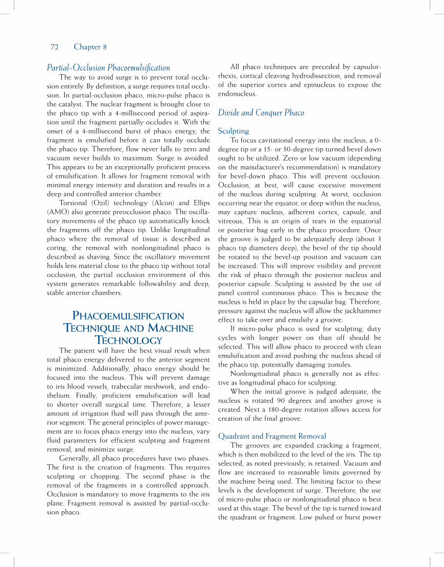
72 Chapter 8
Partial-Occlusion PhacoemulsificationThe way to avoid surge is to prevent total occlu-
sion entirely. By definition, a surge requires total occlu-sion. In partial-occlusion phaco, micro-pulse phaco is the catalyst. The nuclear fragment is brought close to the phaco tip with a 4-millisecond period of aspira-tion until the fragment partially occludes it. With the onset of a 4-millisecond burst of phaco energy, the fragment is emulsified before it can totally occlude the phaco tip. Therefore, flow never falls to zero and vacuum never builds to maximum. Surge is avoided. This appears to be an exceptionally proficient process of emulsification. It allows for fragment removal with minimal energy intensity and duration and results in a deep and controlled anterior chamber.
Torsional (Ozil) technology (Alcon) and Ellips (AMO) also generate preocclusion phaco. The oscilla-tory movements of the phaco tip automatically knock the fragments off the phaco tip. Unlike longitudinal phaco where the removal of tissue is described as coring, the removal with nonlongitudinal phaco is described as shaving. Since the oscillatory movement holds lens material close to the phaco tip without total occlusion, the partial occlusion environment of this system generates remarkable followability and deep, stable anterior chambers.
PhacoeMulsification technique and Machine
technoloGyThe patient will have the best visual result when
total phaco energy delivered to the anterior segment is minimized. Additionally, phaco energy should be focused into the nucleus. This will prevent damage to iris blood vessels, trabecular meshwork, and endo-thelium. Finally, proficient emulsification will lead to shorter overall surgical time. Therefore, a lesser amount of irrigation fluid will pass through the ante-rior segment. The general principles of power manage-ment are to focus phaco energy into the nucleus, vary fluid parameters for efficient sculpting and fragment removal, and minimize surge.
Generally, all phaco procedures have two phases. The first is the creation of fragments. This requires sculpting or chopping. The second phase is the removal of the fragments in a controlled approach. Occlusion is mandatory to move fragments to the iris plane. Fragment removal is assisted by partial-occlu-sion phaco.
All phaco techniques are preceded by capsulor-rhexis, cortical cleaving hydrodissection, and removal of the superior cortex and epinucleus to expose the endonucleus.
Divide and Conquer Phaco
SculptingTo focus cavitational energy into the nucleus, a 0-
degree tip or a 15- or 30-degree tip turned bevel down ought to be utilized. Zero or low vacuum (depending on the manufacturer’s recommendation) is mandatory for bevel-down phaco. This will prevent occlusion. Occlusion, at best, will cause excessive movement of the nucleus during sculpting. At worst, occlusion occurring near the equator, or deep within the nucleus, may capture nucleus, adherent cortex, capsule, and vitreous. This is an origin of tears in the equatorial or posterior bag early in the phaco procedure. Once the groove is judged to be adequately deep (about 3 phaco tip diameters deep), the bevel of the tip should be rotated to the bevel-up position and vacuum can be increased. This will improve visibility and prevent the risk of phaco through the posterior nucleus and posterior capsule. Sculpting is assisted by the use of panel control continuous phaco. This is because the nucleus is held in place by the capsular bag. Therefore, pressure against the nucleus will allow the jackhammer effect to take over and emulsify a groove.
If micro-pulse phaco is used for sculpting, duty cycles with longer power on than off should be selected. This will allow phaco to proceed with clean emulsification and avoid pushing the nucleus ahead of the phaco tip, potentially damaging zonules.
Nonlongitudinal phaco is generally not as effec-tive as longitudinal phaco for sculpting.
When the initial groove is judged adequate, the nucleus is rotated 90 degrees and another grove is created. Next a 180-degree rotation allows access for creation of the final groove.
Quadrant and Fragment RemovalThe grooves are expanded cracking a fragment,
which is then mobilized to the level of the iris. The tip selected, as noted previously, is retained. Vacuum and flow are increased to reasonable limits governed by the machine being used. The limiting factor to these levels is the development of surge. Therefore, the use of micro-pulse phaco or nonlongitudinal phaco is best used at this stage. The bevel of the tip is turned toward the quadrant or fragment. Low pulsed or burst power

The Phaco Machine 73
is applied at a level high enough to emulsify the frag-ment without driving it away from the phaco tip.
“Chatter” is defined as a fragment bouncing away from the phaco tip due to excessively aggressive appli-cation of phaco energy.
Epinucleus and Cortex RemovalIf cortical cleaving hydrodissection has been per-
formed, the endonucleus is removed first as noted above. The result is a shell of epinucleus and cortex. For removal of epinucleus and cortex, the vacuum is decreased while flow is maintained. This will allow for grasping of the epinucleus just deep to the ante-rior capsule. The low vacuum will help the tip hold the epinucleus on the phaco tip without breaking off chunks. High vacuum results in breaking off pieces of epinucleus and cortex, making it more difficult to remove. With the fluid parameters balanced, the epi-nucleus/cortex scrolls around the equator and can be pulled to the level of the iris. There, low power pulsed or hyper pulse phaco is employed for emulsification.
Stop and Chop PhacoGroove creation is performed as noted above
under divide and conquer sculpting techniques. Once a single deep groove is adequate vacuum and flow are increased to improve holding capability of the phaco tip. The nucleus is rotated 90 degrees and the phaco tip is driven into the mass of one heminucleus using pulsed linear phaco. The sleeve should be 1 mm from the base of the bevel of the phaco tip to create adequate exposed needle length for sufficient holding power. Excessive phaco energy application is to be avoided, as this will cause nucleus immediately adja-cent to the tip to be emulsified. The gap thus created in the vicinity of the tip is responsible for interfering with the seal around the tip and therefore the capabil-ity of vacuum to hold the nucleus. The nucleus will then pop off the phaco tip, making chopping more difficult. With a good seal, the heminucleus can be drawn toward the incision and the chopper can be inserted at the endonucleus-epinucleus junction. The chopper is then drawn down and left, while the phaco tip is pushed up and right. This will result in chopping of the heminucleus.
After the first chop, a second similar chop is performed so the heminucleus is divided into three pieces. One pie-shaped piece of nucleus thus created is elevated to the iris plane (occlusion is utilized to move fragments) and removed with low power hyper-pulsed phaco or nonlongitudinal phaco as discussed
in the divide and conquer section. Each fragment and the remaining heminucleus are removed in turn. Epinucleus and cortex removal are also performed as noted above.
Phaco ChopPhaco chop requires no sculpting. Therefore,
the procedure is initiated with high vacuum and flow and linear pulsed or micro-pulse phaco power. Nonlongitudinal phaco does not work well for the actual chopping as the shaving movement of the phaco tip prevents an adequate vacuum seal to assist chop-ping and fragment mobilization. For a 0-degree tip, especially when emulsifying a hard nucleus, a small trough may be required to create adequate room for the phaco tip to push deep into the nucleus. For a 15- or a 30-degree tip, the tip should be rotated bevel down to engage the nucleus. The phaco tip should be encased within the endonucleus with the minimal amount of power necessary. All chopping proce-dures require 1 mm of exposed phaco tip to create adequate holding power for chopping. If the phaco tip is inserted into the nucleus with excess power, the adjacent nucleus will be emulsified, creating a poor seal between nucleus and tip. This will make it impos-sible to remove fragments, as the tip will just “let go” of the nuclear material. Additionally, the bevel should be turned toward the fragment to create a seal between tip and fragment, allowing vacuum to build and create holding power.
Horizontal ChopA few bursts or pulses of phaco energy will allow
the tip to be encased within the nucleus. It then can be drawn toward the incision to allow the chopper access to the epi-endo nuclear junction. The chopping instrument is passed over the nucleus and under the anterior capsule into this junction. It may be helpful to rotate the chopper to horizontal as it passes below the anterior capsule. If the nucleus comes off the phaco tip, excessive power has produced a space around the tip, impeding vacuum holding power as noted above. Pulling the chopper down and left and pushing the phaco tip up and right will generate the first chop. Minimal rotation of the nucleus will allow for creation of the second chop. The first pie-shaped piece of nucleus is mobilized with high vacuum and elevated to the iris plane. There it is emulsified with low linear hyper-pulse or nonlongitudinal power, high vacuum, and moderate flow.
74 Chapter 8
Vertical ChopOnce the phaco tip is embedded within the nucle-
us as previously described, a sharp chopper (Nichamin, Katena, Denville, NJ) is pushed down into the mass of the nucleus at the same time the phaco tip is elevated. The chopper is then drawn down and left and the phaco tip up and right. This creates a cleavage plane in the nucleus. With a second chop the fragment created is mobilized to the iris plane and removed as noted above. When the nucleus is noted to be hard, the pro-cess of rotation and vertical chopping is repeated until the entire nucleus is chopped. Usually, at this point, the nucleus loses its rigidity, allowing the segments to be mobilized without difficulty.
Microincisional PhacoThe development of micro-pulse and nonlongitu-
dinal phaco (“cold phaco”) has led to the performance of phaco through increasingly small incisions with tighter irrigation sleeves, no irrigation sleeves, and decreased inflow.
Bimanual Microincisional PhacoTwo incisions are created 90 degrees apart. Their
size is dependant on the instrumentation. Twenty-gauge instruments require 1.4-mm incisions while 21-gauge instruments require 1.2-mm incisions. There is no irrigating sleeve on the phaco tip. The instru-mentation for this procedure is important and the relationship between the instrument and incision size is essential. If the wound is too tight, it is difficult to manipulate the instruments. If the wound is too large, excessive outflow permits chamber shallowing with an unstable anterior segment. The instruments can be moved forward and backward through the incisions without creating corneal distortion. If the instruments are angled in the incision, sufficient corneal distortion occurs that the procedure is appreciably more difficult. The irrigating chopper should be parallel to the iris and above it. The inflow current thus created tends to wash fragments toward the unsleeved phaco tip. The small incisions cause less disruption of the blood-aqueous barrier and are more stable and secure. Presently a new incision is created for intraocular lens (IOL) implanta-tion. In the future, with insertion of an IOL through the 1.4-mm incision, there should be less disruption of ocular integrity, immediate return to full activities, and less risk of postoperative wound complications.
Microincisional Coaxial PhacoA thin-walled, flared 21-gauge phaco tip and thin-
ner irrigation sleeve is available for Infinity (Alcon) machines and now permits phaco though a 2.2-mm incision. Despite the smaller incision, inflow is adequate to maintain a deep anterior chamber. The procedure is no more difficult than when performed through a 2.8-mm incision. Alcon also manufactures a one-piece acrylic IOL and injector that is capable of implanting the IOL through the 2.2-mm unenlarged incision.
Irrigation and AspirationSimilar to phaco, anterior chamber stability during
irrigation and aspiration (I/A) is due to a equilibrium of inflow and outflow. Wound outflow can be mini-mized by employing a soft sleeve around the I/A tip. Combined with a small incision (2.8 to 3 mm), a deep and stable anterior chamber will result. Generally, a 0.3-mm I/A tip is used. With this orifice, a vacuum of 500 mmHg and flow of 20 cc/min is excellent to tease cortex from the capsular fornices. Linear vacuum allows the cortex to be grasped under the anterior capsule with low vacuum and drawn into the center of the pupil at the iris plane. There, in the safety of a deep anterior chamber, vacuum can be increased and the cortex aspirated.
Bimanual I/A is also a viable procedure. A 21-gauge irrigating cannula provides inflow through one paracentesis while an unsleeved 21-gauge aspiration cannula is used through the opposite paracentesis. The instruments can be easily switched, making removal of stubborn cortex considerably easier.
VitrectomyMost phaco machines are equipped with a vitreous
cutter that is activated by compressed air or by electric motor. As noted previously, preservation of a deep anterior chamber is contingent upon an equilibrium of inflow and outflow. For vitrectomy, a 23-gauge cannu-la, or chamber maintainer, inserted through a paracen-tesis, provides inflow. Bottle height should be adequate to prevent chamber collapse. The vitrector should be inserted through another paracentesis. If equipped with a Charles Sleeve, this should be removed and dis-carded. Utilizing a flow of 20 cc/min, vacuum of 250 mmHg, and a cutting rate of 450 or more cuts/min, the vitrector should be placed through the tear in the posterior capsule, orifice facing upward, pulling vitre-ous out of the anterior chamber and back to the plane of the posterior capsule.

The Phaco Machine 75
Alternatively, the vitrector can be inserted through a pars plana incision 3 mm posterior to the limbus. Recently, 25-gauge vitrectomy instruments have been introduced. Their ultimate utility, however, is not yet clear. In an effort to better visualize the vitreous for thorough vitrectomy, unpreserved sterile prednisone acetate (Kenalog), previously purchased from a formu-lating pharmacy, can be injected into the vitreous. The prednisone particles adhere to the vitreous strands, making the invisible visible.
suMMaryThe phaco process is a balance of technology and
technique. Awareness of the principles that influence phaco machine settings is a prerequisite for the perfor-mance of a proficient and safe operation. Additionally, often during the procedure, there is a demand for modification of the initial parameters. A thorough understanding of fundamental principles will enhance
the capability of the surgeon for appropriate response to this requirement. It is this crucial attitude that through relentless evaluation of the interaction of the machine, and the phaco procedure, the skillful surgeon will find innovative methods to enhance technique.
BiBlioGraPhyBuratto L, Osher RH, Masket S, eds. Cataract Surgery in Complicated
Cases. Thorofare, NJ: SLACK Incorporated; 2001.Fishkind WJ, ed. Complications in Phacoemulsification: Recognition,
Avoidance, and Management. New York, NY: Thieme Publish-ers; 2001.
Fishkind WJ. Pop Goes the Microbubbles. ESCRS Film Festival Grand Prize Winner, 1998.
Fishkind WJ, Neuhann TF, Steinert RF. The Phaco Machine in Cata-ract Surgery Technique: Complications & Management. 2nd ed. Phila-delphia, PA: WB Saunders Co; 2004.
Miyoshi T. From phaco-cutting to true phacoemulsification. Vid-eo competition grand prize winner ASCRS, ESCRS 2007.
Seibel BS. Phacodynamics: Mastering the Tools and Techniques of Phaco-emulsification Surgery. 3rd ed. Thorofare, NJ: SLACK Incorpo-rated; 2000.
77
Defining ParametersPhaco parameters represent a group of numbers
that control the various functions of a phaco machine. Although all phaco machines obey the same general principles, each model of machine is unique; therefore, the parameters do not transfer identically from machine to machine. Each surgeon should adjust to best effect, or optimize, his or her parameters for each machine he or she uses. While surgical facility or ease of use and absence of complications represent intraoperative criteria for optimization, early postoperative outcomes best reflect the impact of phaco on the eye.1
Recording and evaluating outcomes on a consis-tent basis allows ongoing improvement in all facets of surgery, including phaco parameters. The clarity of the cornea and aqueous vary directly with the opti-mization of phaco parameters; they can be measured quickly at the slit lamp and more precisely with optical coherence tomography, specular microscopy, and laser flare photometry. The uncorrected visual acuity at the first postoperative examination may also be used to assess phaco parameters (as long as surgical tech-nique, intraocular lens power calculations, and correc-tion of pre-existing keratometric astigmatism, among other factors, are held constant or at least taken into account).2
Programming phaco parameters varies with surgi-cal technique. An understanding of the actions of aspi-ration, vacuum, and power allows the surgeon to begin with a rational selection and make changes on the fly to improve qualities such as sculpting, followability, hold-ing power, chamber stability, and evacuation of mate-rial. A sample of parameters for a variety of machines is given at the end of this section as a starting point for each surgeon’s customization process.
irrigation: gravity anD Pressure
The anterior segment of the eye exhibits elastic-ity, which means that the cornea, limbus, and zonulo-capsular complex respond to pressure by allowing an increase in volume.3 The response of the cornea mea-sured on an artificial anterior chamber is in the range of 0.34 to 1.6 mmHg/microliter, while the response of the anterior chamber measured during cataract surgery is 0.0126 mmHg/microliter.4 Because the amount of ocular elasticity is low, the intraocular pressure (IOP) during phaco is essentially determined by the height of the irrigation fluid above the eye and the rate of leak-age of fluid out of the eye. The fluid pressure at the base of a column of water can be calculated (in mmHg,
Chapter
Setting Phaco Parameters
Mark Packer, MD, FACS; I. Howard Fine, MD; and Richard S. Hoffman, MD
9

78 Chapter 9
at standard atmospheric pressure) using the following equation:
Pressure (mmHg) = Column height (cm) (10/13.6)
where the density of mercury is 13.6 g/cm3 and the density of water is 1 g/cm3.
The measured IOP closely agrees with the calculat-ed IOP unless there is significant incisional leakage.5
Chamber stability means the maintenance of vol-ume in the working space of the aqueous environment, from the apex of the corneal endothelium to the cen-tral posterior capsule. The balance between irrigation on the one hand and aspiration plus leakage on the other hand determines this volume. Leakage can be minimized by proper incision construction.
However, the aspiration flow rate of fluid exiting the eye can increase suddenly but predictably during surgery due to the phenomenon known as surge flow. Surge flow means the loss of aqueous volume in the working space of the anterior segment that can occur when material that has occluded the phaco tip is sud-denly evacuated from the chamber. The surge occurs because the high vacuum reached during occlusion actually exerts its force throughout the aspiration tub-ing and creates a pinching or narrowing of the tubing. When the vacuum is released, the pinched tubing expands and fluid rushes in to fill the void.
Phaco machine innovations such as low compli-ance tubing and rigid cassettes minimize the elasticity in the system and reduce surge flow. Other designs intended to reduce surge include the aspiration bypass system (a small aperture on the side of the phaco tip that allows fluid flow into the handpiece despite an occlusion on the front of the tip) and in-line filters (mesh to trap material upstream from a small aperture, which poses a size restriction to flow).6
Regardless of specific phaco machine technol-ogy, irrigation must be adequate to at least balance aspiration plus leakage. We depend on gravity and atmospheric pressure to provide irrigation; however, pressurization of the irrigation bottle with forced gas may also be employed. In general, the intraoperative response of the surgeon to an unstable chamber should first be to raise the irrigation bottle. If the instability is occurring due to surge, then reducing the vacuum level makes sense. If the instability is unrelated to occlusion or surge, then it is time to reduce the aspi-ration flow rate. In the postoperative analysis of an unstable chamber, the surgeon should also examine the incision construction and watch for leakage.
asPiration anD Peristaltic PumPs
In a peristaltic pump system, depression of the foot pedal in position 2 directly controls the rate at which the pinch roller rotates. Machines offer fixed rates of flow or linear control of flow, as well as alterations in the flow rate when the machine senses an occlu-sion (ie, in the face of rising vacuum). No vacuum is present in peristaltic systems until the tip begins to become occluded and resistance to flow is sensed. Vacuum pressure rises as flow is reduced by material on the tip. Aspiration flow ceases at occlusion and the maximum vacuum is reached. The maximum vacuum level is set by the surgeon as one of the parameters of a peristaltic system, but in fact this setting specifies the vacuum level at which the pump stops. One mecha-nism for reducing surge involves an occlusion mode setting with reduction of maximum vacuum, so that when the occlusion breaks (as the material is emulsi-fied and evacuated), the fall in vacuum is reduced (the fall is reduced because the vacuum level falls from a lesser height). Ultrasound power is usually necessary at the point of occlusion to emulsify material and allow evacuation.
In general, the higher the flow rate, the faster fluid and material will move toward the phaco tip and the faster vacuum will rise when material occludes the tip. Machines offer independent control of vacuum rise time or ramp, essentially changing the pump speed as the machine first senses resistance to flow, in order to either speed up or slow down the process of reach-ing full occlusion (get a firm hold on material more quickly or less quickly).
The concept of followability means the facility with which nuclear material flows toward, is held by, and evacuated through the phaco tip. One antonym of followability is chatter, which means that material repeatedly bounces off the phaco tip without follow-ing the aspiration flow up the tube. The metaphor of magnetism is sometimes used to describe the attrac-tion of material to the tip; in fact, it is the aspiration flow that brings the material toward the tip. In coaxial phaco (with the irrigation sleeve on the phaco tip), the irrigation stream tends to push material away so that aspiration must overcome irrigation for magnetic attraction to occur. In both coaxial and biaxial phaco, longitudinal ultrasonic vibration of the phaco tip also acts as a repulsive force that must be overcome by aspiration flow and, during occlusion, by vacuum pressure, to bring material and hold it on the tip as it

Setting Phaco Parameters 79
is mobilized and emulsified. Alleviating the repulsive force of longitudinal tip motion has been the impetus behind the development of nonlongitudinal sonic and ultrasonic energy delivery systems, such as oscillatory, torsional, or transverse tip motions. The balancing of these competing forces at the phaco tip underlies much of the logic of setting parameters for efficient surgery.
vacuum anD venturi PumPsIn a Venturi pump (named for the Italian physicist
Giovanni Battista Venturi), the foot pedal directly controls the application of vacuum; aspiration flow occurs in response to vacuum pressure. According to the classic Venturi principle, it is the flow of pres-surized gas through a narrowed tube that creates the vacuum. Unlike a peristaltic pump, with which vacuum does not exist until there is resistance to flow, with a Venturi pump vacuum is always present. The surgeon sets the maximum vacuum level as one of the param-eters. There is no setting for aspiration flow. The vacuum increases in a linear fashion as the foot pedal is depressed in foot position 2. Machines that feature a bidirectional foot pedal also allow control of vacuum with yaw (ie, movement of the foot pedal in a direction parallel [rather than perpendicular] to the floor). This feature permits greater flexibility in separately control-ling the application of vacuum and ultrasound power.
Conventional wisdom regards Venturi pumps as more aggressive than peristaltic pumps. This percep-tion comes about primarily because of surge. Vacuum increases as the surgeon depresses (or yaws) the foot pedal in order to evacuate material, and the vacuum remains high even after the material is evacuated unless the surgeon actively reduces the vacuum by moving the foot pedal. This process is in contradistinc-tion to a peristaltic pump in which the vacuum will drop to zero once the occlusion has passed regardless of foot pedal action. Of course, surge can still occur with a peristaltic pump because of stored energy in the tubing and cassette (low compliance systems are designed to reduce this problem). Nevertheless, with an appropriate initial Venturi vacuum setting and a good foot pedal control, one can maintain a stable chamber. Therefore, not only do Venturi pumps have a reputation for being more aggressive, they also have a reputation for allowing exceptionally rapid clearing of material, excellent followability, and fast surgery.
One of the technological advances that has made Venturi pumps safer involves the insertion of a filter
and flow restriction device in the aspiration line. The capacious filter element traps emulsate so that it will not clog the small diameter flow restrictor, which is placed just up the aspiration line. The inner diameter of the flow restrictor is about the same as the aperture on an aspiration tip used for removing cortex and vis-coelastic (0.2 mm). This device has the effect of greatly reducing or eliminating surge because it limits the rate at which fluid can move up the line. Fortunately, the flow restriction does not impact flow at the usual rates applied during phaco. In this light, it is interesting to note that one of the situations where Venturi is most safe and efficient is during irrigation/aspiration.
Power anD Power moDulations
The ability to variably control the application of ultrasound power to within a period of several mil-liseconds has revolutionized phaco technology. The first generation of phaco machines only allowed appli-cation of continuous power at a fixed level. Following the development of linear power control, the first power modulations were developed, pulse and burst modes. In 2001, we showed how application of these modulations reduces the use of ultrasound energy and permits rapid visual rehabilitation after surgery.7 We also showed in that reduction of effective phaco time correlates with improved uncorrected visual acuity at the first visit after surgery. Subsequently, the intro-duction of millisecond level control and variable duty cycle applications has permitted further reduction of ultrasound energy and eliminated the risk of thermal injury to the cornea, paving the way for the adoption of biaxial microincision cataract surgery.8 Surgeons should try a variety of power settings, including pulse and burst modes, variable duty cycles, and percentage power ceilings, in order to develop parameters best suited to their individual techniques. Machines also feature standard longitudinal, torsional, and transverse tip motions that can be customized in amplitude to suit a variety of techniques.
Intraoperative awareness and moment-to-moment assessment of surgical success offer the best opportu-nity to alter settings and improve results. The surgeon should recognize that insufficient holding implies a need for greater vacuum, whereas an uncomfortable amount of surge calls for a reduction in vacuum. Poor followability may require increased aspiration flow or vacuum if the problem is bringing material to the tip, or higher power if material comes to the tip but then
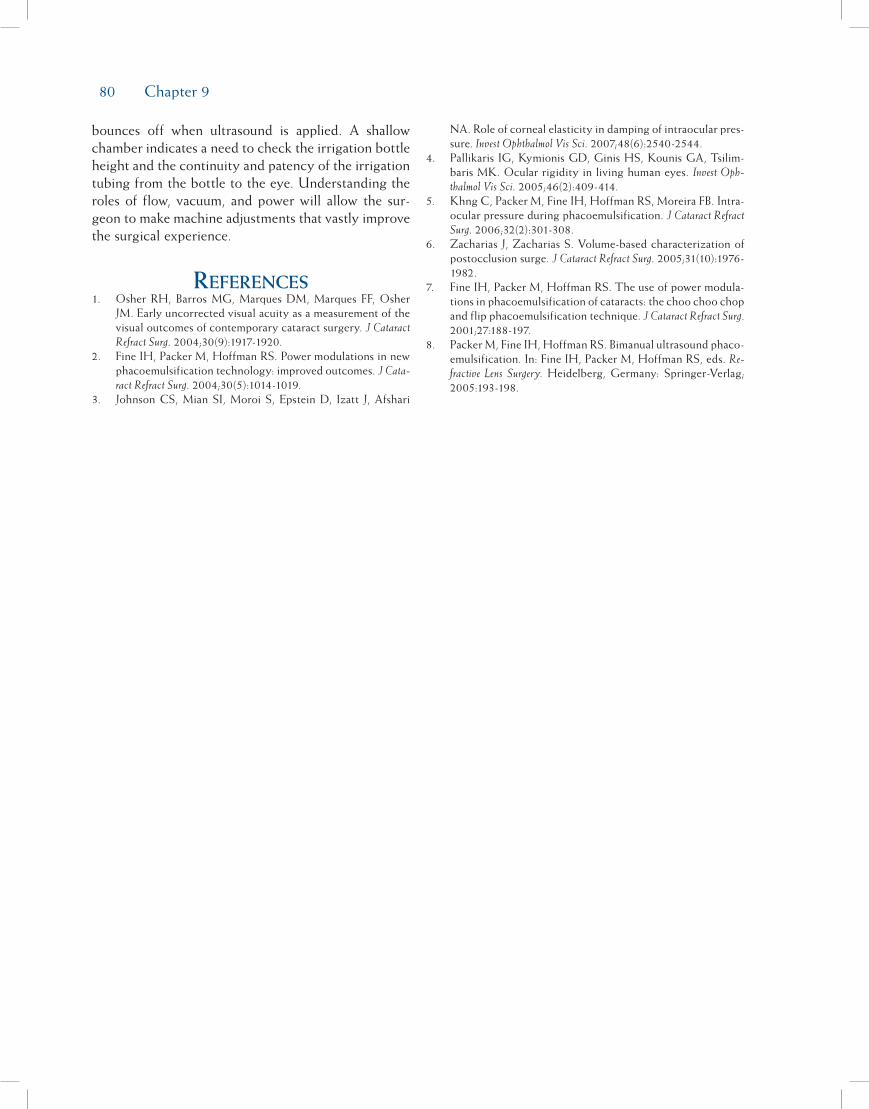
80 Chapter 9
bounces off when ultrasound is applied. A shallow chamber indicates a need to check the irrigation bottle height and the continuity and patency of the irrigation tubing from the bottle to the eye. Understanding the roles of flow, vacuum, and power will allow the sur-geon to make machine adjustments that vastly improve the surgical experience.
references1. Osher RH, Barros MG, Marques DM, Marques FF, Osher
JM. Early uncorrected visual acuity as a measurement of the visual outcomes of contemporary cataract surgery. J Cataract Refract Surg. 2004;30(9):1917-1920.
2. Fine IH, Packer M, Hoffman RS. Power modulations in new phacoemulsification technology: improved outcomes. J Cata-ract Refract Surg. 2004;30(5):1014-1019.
3. Johnson CS, Mian SI, Moroi S, Epstein D, Izatt J, Afshari
NA. Role of corneal elasticity in damping of intraocular pres-sure. Invest Ophthalmol Vis Sci. 2007;48(6):2540-2544.
4. Pallikaris IG, Kymionis GD, Ginis HS, Kounis GA, Tsilim-baris MK. Ocular rigidity in living human eyes. Invest Oph-thalmol Vis Sci. 2005;46(2):409-414.
5. Khng C, Packer M, Fine IH, Hoffman RS, Moreira FB. Intra-ocular pressure during phacoemulsification. J Cataract Refract Surg. 2006;32(2):301-308.
6. Zacharias J, Zacharias S. Volume-based characterization of postocclusion surge. J Cataract Refract Surg. 2005;31(10):1976-1982.
7. Fine IH, Packer M, Hoffman RS. The use of power modula-tions in phacoemulsification of cataracts: the choo choo chop and flip phacoemulsification technique. J Cataract Refract Surg. 2001;27:188-197.
8. Packer M, Fine IH, Hoffman RS. Bimanual ultrasound phaco-emulsification. In: Fine IH, Packer M, Hoffman RS, eds. Re-fractive Lens Surgery. Heidelberg, Germany: Springer-Verlag; 2005:193-198.

81
Perhaps one of the simplest steps in the phacoemul-sification procedure is the insertion of the intraocular lens (IOL). The transition from single-piece all poly-methylmethacrylate (PMMA) IOLs to foldable acrylic and silicone IOLs has allowed for lens insertion through smaller incisions with less surgically induced astigma-tism and faster visual recovery. At the time of intro-duction of foldable IOLs, insertion was accomplished with folding forceps and inserters and these eventu-ally were replaced with cartridge injectors that further simplified the IOL insertion technique. Adjunctive capsular bag prostheses, such as the capsular tension ring (CTR), added an additional tool for facilitating phacoemulsification in difficult and challenging cases and ensuring adequate IOL centration following these procedures. Even with the best techniques, complica-tions may develop requiring alternatives for traditional capsular bag implantation of IOLs. In this chapter, we will review the techniques for loading and implanting foldable IOLs utilizing folding forceps and cartridge injectors. In addition, a review of the utility of CTRs and techniques for in-the-bag and sulcus implantation of foldable IOLs will guarantee that the ideal post-operative result will be achieved in both routine and complicated cases.
Folding and insertion Forceps For three-piece
Foldable intraocular lensesAlthough for the most part folding forceps have
been supplanted by cartridge injector systems, knowl-edge of their utilization is important. On occasion, folding forceps are utilized for implantation and posi-tioning of foldable IOLs for iris fixation or when car-tridge injector systems fail or are not available.
A greater amount of energy is required to fold an IOL than to hold it in its folded configuration. By cre-ating two separate instruments to fold and insert IOLs, folders could be made with special features that allowed for more precise and consistent folding, and the inser-tion forceps could be designed more finely for insertion through smaller incisions. A host of folding forceps and inserters have been created including the Nichamin III Loader and Nichamin II Inserter (Rhein Medical, Tampa, FL) (Figure 10-1), Nordan Unifold folding for-ceps (ASICO, Westmont, IL), and the Buratto Silicone and Acrylic IOL Implantation Forceps (ASICO), just to name a few. Most three-piece foldable lenses are being manufactured with PMMA haptics to increase haptic stability and decrease the rate of lens decen-tration. Older lens insertion techniques for use with
Foldable Intraocular Lens Implantation
Richard S. Hoffman, MD; I. Howard Fine, MD; and Mark Packer, MD, FACS
Chapter10
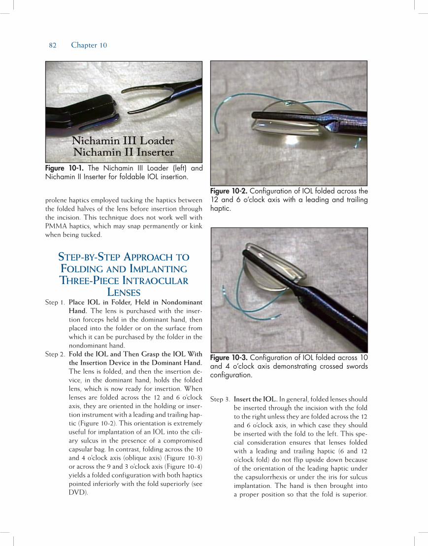
82 Chapter 10
prolene haptics employed tucking the haptics between the folded halves of the lens before insertion through the incision. This technique does not work well with PMMA haptics, which may snap permanently or kink when being tucked.
step-by-step approach to Folding and implanting three-piece intraocular
lensesStep 1. Place IOL in Folder, Held in Nondominant
Hand. The lens is purchased with the inser-tion forceps held in the dominant hand, then placed into the folder or on the surface from which it can be purchased by the folder in the nondominant hand.
Step 2. Fold the IOL and Then Grasp the IOL With the Insertion Device in the Dominant Hand. The lens is folded, and then the insertion de-vice, in the dominant hand, holds the folded lens, which is now ready for insertion. When lenses are folded across the 12 and 6 o’clock axis, they are oriented in the holding or inser-tion instrument with a leading and trailing hap-tic (Figure 10-2). This orientation is extremely useful for implantation of an IOL into the cili-ary sulcus in the presence of a compromised capsular bag. In contrast, folding across the 10 and 4 o’clock axis (oblique axis) (Figure 10-3) or across the 9 and 3 o’clock axis (Figure 10-4) yields a folded configuration with both haptics pointed inferiorly with the fold superiorly (see DVD).
Step 3. Insert the IOL. In general, folded lenses should be inserted through the incision with the fold to the right unless they are folded across the 12 and 6 o’clock axis, in which case they should be inserted with the fold to the left. This spe-cial consideration ensures that lenses folded with a leading and trailing haptic (6 and 12 o’clock fold) do not flip upside down because of the orientation of the leading haptic under the capsulorrhexis or under the iris for sulcus implantation. The hand is then brought into a proper position so that the fold is superior.
Figure 10-1. The Nichamin III Loader (left) and Nichamin II Inserter for foldable IOL insertion.
Figure 10-2. Configuration of IOL folded across the 12 and 6 o’clock axis with a leading and trailing haptic.
Figure 10-3. Configuration of IOL folded across 10 and 4 o’clock axis demonstrating crossed swords configuration.
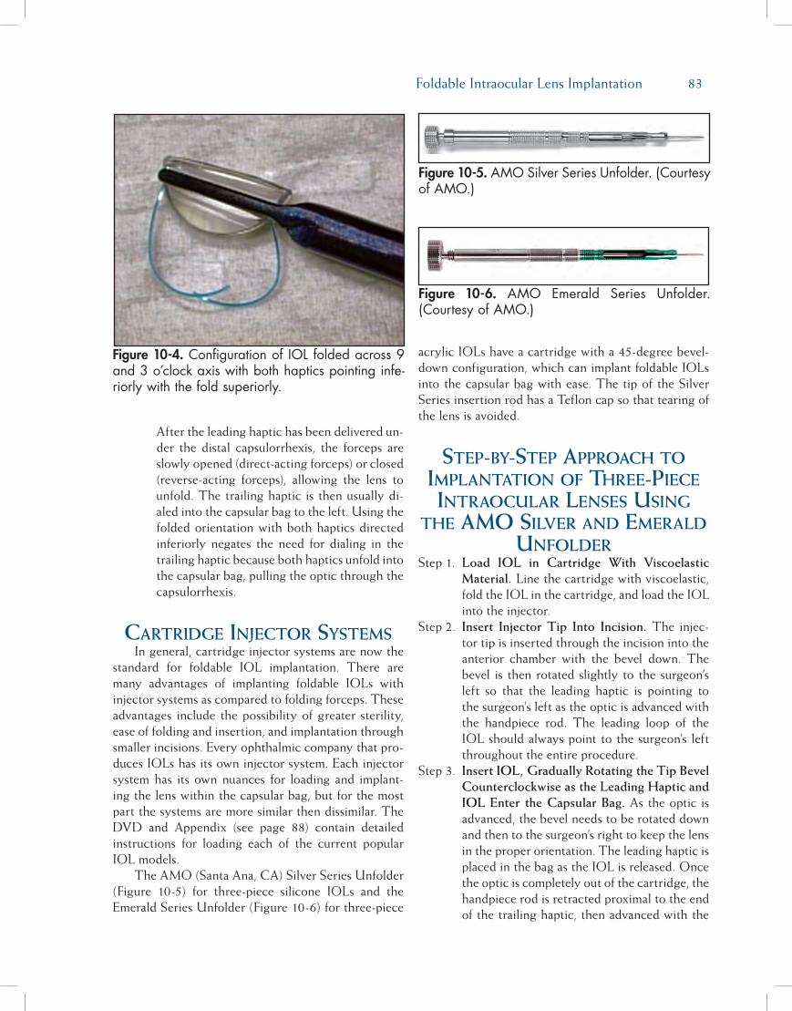
Foldable Intraocular Lens Implantation 83
After the leading haptic has been delivered un-der the distal capsulorrhexis, the forceps are slowly opened (direct-acting forceps) or closed (reverse-acting forceps), allowing the lens to unfold. The trailing haptic is then usually di-aled into the capsular bag to the left. Using the folded orientation with both haptics directed inferiorly negates the need for dialing in the trailing haptic because both haptics unfold into the capsular bag, pulling the optic through the capsulorrhexis.
cartridge injector systems In general, cartridge injector systems are now the
standard for foldable IOL implantation. There are many advantages of implanting foldable IOLs with injector systems as compared to folding forceps. These advantages include the possibility of greater sterility, ease of folding and insertion, and implantation through smaller incisions. Every ophthalmic company that pro-duces IOLs has its own injector system. Each injector system has its own nuances for loading and implant-ing the lens within the capsular bag, but for the most part the systems are more similar then dissimilar. The DVD and Appendix (see page 88) contain detailed instructions for loading each of the current popular IOL models.
The AMO (Santa Ana, CA) Silver Series Unfolder (Figure 10-5) for three-piece silicone IOLs and the Emerald Series Unfolder (Figure 10-6) for three-piece
acrylic IOLs have a cartridge with a 45-degree bevel-down configuration, which can implant foldable IOLs into the capsular bag with ease. The tip of the Silver Series insertion rod has a Teflon cap so that tearing of the lens is avoided.
step-by-step approach to implantation oF three-piece intraocular lenses using
the amo silver and emerald unFolder
Step 1. Load IOL in Cartridge With Viscoelastic Material. Line the cartridge with viscoelastic, fold the IOL in the cartridge, and load the IOL into the injector.
Step 2. Insert Injector Tip Into Incision. The injec-tor tip is inserted through the incision into the anterior chamber with the bevel down. The bevel is then rotated slightly to the surgeon’s left so that the leading haptic is pointing to the surgeon’s left as the optic is advanced with the handpiece rod. The leading loop of the IOL should always point to the surgeon’s left throughout the entire procedure.
Step 3. Insert IOL, Gradually Rotating the Tip Bevel Counterclockwise as the Leading Haptic and IOL Enter the Capsular Bag. As the optic is advanced, the bevel needs to be rotated down and then to the surgeon’s right to keep the lens in the proper orientation. The leading haptic is placed in the bag as the IOL is released. Once the optic is completely out of the cartridge, the handpiece rod is retracted proximal to the end of the trailing haptic, then advanced with the
Figure 10-4. Configuration of IOL folded across 9 and 3 o’clock axis with both haptics pointing infe-riorly with the fold superiorly.
Figure 10-5. AMO Silver Series Unfolder. (Courtesy of AMO.)
Figure 10-6. AMO Emerald Series Unfolder. (Courtesy of AMO.)

84 Chapter 10
bevel down to place the trailing haptic within the bag (Figure 10-7). Placing the bevel com-pletely within the capsulorrhexis at this stage of insertion keeps the optic in place and en-sures placement of the trailing loop.
Step 4. Place the Trailing Haptic in Capsular Bag. Placement of the trailing loop of a foldable acrylic IOL usually requires implantation uti-lizing a Lester hook to dial in the trailing hap-tic. This is easily accomplished by removing the injector cartridge from the incision and placing a hook at the junction of the trailing haptic and the lens optic (Figure 10-8). With slight downward pressure, the hook is pushed distally and under the anterior capsulorrhex-is until the end of the trailing haptic is seen to pass under the rhexis. A 1 to 3 clock hour clockwise rotation of the hook will usually fa-cilitate placement of the trailing haptic.
intraocular lens implantation in the
presence oF a compromised capsular bag
When faced with a compromised capsular bag following nucleus and cortex removal, the surgeon must decide the best lens model and location of final implantation to optimize the postoperative result.
An intact capsular bag with compromised zonules can be easily addressed with a CTR and in-the-bag IOL implantation (Figures 10-9A through 10-9C). Utilizing a three-piece IOL with rigid haptics offers the advantage of positioning the IOL haptics in the meridian of zonular weakness or dehiscence in order to support this region of the capsular bag and prevent further lens decentration during postoperative capsule fibrosis. In instances of moderate zonular weakness, implantation of a single-piece acrylic IOL offers the advantage of inducing less zonular stress during implantation of the IOL but little capsular support from the acrylic haptics. When severe or complete zonular dehiscence is present, it is best to implant a three-piece IOL in the sulcus with concurrent iris or scleral fixation to ensure centration.
When the posterior capsule is intact, but a rent or tear in the anterior capsule may compromise IOL inser-tion, implantation of a single-piece acrylic IOL will ensure that the anterior rhexis tear does not extend out to the posterior capsule. These lenses typically unfold after implantation in a very slow, controlled manner that places little if any stress on the capsule. A three-piece IOL can also be implanted in these compromised capsular bags; however, care should be taken to not stress the capsule in the location of the anterior tear. Dialing in of these IOLs should be accomplished with all forces directed in a location distant from the tear.
When the posterior capsule is torn, IOLs can be placed within the capsular bag if the tear is small or
Figure 10-7. Following injection of the optic into the capsular bag, the injector rod is withdrawn proxi-mal to the trailing haptic and then inserted into the eye carrying the trailing haptic through the anterior rhexis and into the capsular bag.
Figure 10-8. Dialing in of the trailing haptic is accomplished by placing a hook at the junction of the lens optic and the trailing haptic and pushing downward slightly with a 1 to 3 clock hour clock-wise rotation.

Foldable Intraocular Lens Implantation 85
converted to a continuous posterior capsulorrhexis. However, under most circumstances it is safer to implant the IOL in the ciliary sulcus to prevent lens decentration or subluxation into the posterior cham-ber. Single-piece acrylic IOLs have been reported to cause pigment dispersion and glaucoma secondary to iris chaffing from the sharp anterior edges of the hap-tics.1,2 For this reason, it is preferred to implant three-piece IOLs with a rounded anterior optic edge in the ciliary sulcus. In addition, if the anterior rhexis is intact
and smaller than 6 mm, the optic can be captured behind the rhexis after sulcus implantation by pressing down on one edge of the optic until it prolapses behind the rhexis and then pressing the other edge, 180 degrees away from the first location, until the entire optic is posterior to the anterior rhexis (Figure 10-10). Implantation of an IOL into the sulcus in the presence of a torn posterior capsule is a simple procedure and can be accomplished with standard cartridge injector systems.
Figure 10-9A. Large zonular dehiscence (arrow). Figure 10-9B. Implantation of CTR with vector forces directed toward area of zonular dehiscence to prevent dehiscence extension.
Figure 10-9C. Dialing in of three-piece IOL with PMMA haptics with vector forces directed toward the region of zonular dehiscence.
Figure 10-10. Optic capture through the anterior capsulorrhexis accomplished with downward pres-sure on the edge of the IOL optic with a blunt Lester hook.

86 Chapter 10
step-by-step approach to sulcus implantation oF
three-piece intraocular lens in the presence oF a torn
capsuleStep 1. Manage Vitreous and Create Space for Sul-
cus Placement of IOL With Dispersive Oph-thalmic Viscoelastic Devices. After appropri-ate vitreous clean-up (if needed), a dispersive viscoelastic is injected into the capsular bag to tamponade the posterior capsule and prevent further vitreous prolapse. Additional visco-elastic is injected between the anterior capsule and the iris, distal to the incision site and in the subincisional location (Figure 10-11). It is best to create an incision slightly larger than ordinarily utilized for routine lens insertion to place less stress on the globe during cartridge insertion and reduce the chances of prolapsing additional vitreous into the anterior chamber.
Step 2. Place Leading Haptic and Optic Under the Distal Iris Margin. The cartridge injector is inserted into the eye, bevel down, and the IOL is gently injected with the leading haptic pointing to the left in its proper orientation. Before the optic exits the cartridge, the leading haptic is placed behind the iris and the optic is also pushed under the iris before it completely unfolds. Placing the optic under the distal iris
margin will prevent the optic from flipping into the wrong orientation as it unfolds (Figure 10-12).
Step 3. Dial the Trailing Haptic Into the Sulcus. The optic and trailing haptic are then ejected from the cartridge and the trailing haptic is dialed into the ciliary sulcus utilizing a Lester hook placed at the trailing haptic optic junction (see DVD). The optic is then centered and pro-lapsed behind the rhexis, miochol is injected into the anterior chamber to constrict the pu-pil, and residual viscoelastic is removed utiliz-ing the irrigation/aspiration handpiece with a low bottle height and low aspiration settings.
Final commentsThe advent of foldable IOLs and cartridge injec-
tor systems has simplified IOL insertion to the point that it is rarely thought of as difficult or challenging. Although most surgeons utilize an assistant to load their lenses prior to insertion, it is important for each surgeon to be aware of the loading and folding tech-niques for each IOL he or she will be using in case his or her assistant is not available or the IOL has been loaded incorrectly.
Challenging IOL insertion scenarios will occasion-al present themselves during a procedure. Knowledge of the use of folding forceps and inserters is important for those rare cases requiring IOL implantation with iris fixation or when cartridge injector systems are not
Figure 10-11. Injection of ophthalmic viscoelastic device in the subincisional region between the anterior capsulorrhexis and the iris to facilitate sul-cus placement of the IOL.
Figure 10-12. Placement of the optic under the dis-tal iris as it is unfolding will prevent the IOL from flipping upside-down.

Foldable Intraocular Lens Implantation 87
available. In addition, when capsular bags are compro-mised from posterior or anterior tears, or from zonular dehiscences, the lens implant technique needs to be modified to ensure a good postoperative result with an adequately centered IOL. Adjunctive capsular devices such as the CTR have improved our ability to address zonular weakness prior to IOL insertion within the capsular bag but even in the best of circumstances and with the best surgical technique, IOLs may need to be implanted within the ciliary sulcus. Understanding the limitations and risks inherent in various clinical settings preoperatively and as they are developing
intraoperatively, in addition to a thorough knowledge of the options for IOL implantation, will ensure the best possible surgical result in both routine and chal-lenging cases.
reFerences1. Iwase T, Tanaka N. Elevated intraocular pressure in second-
ary piggyback intraocular lens implantation. J Cataract Refract Surg. 2005;31:1821-1823.
2. Micheli T, Cheung LM, Sharma S, et al. Acute haptic-in-duced pigmentary glaucoma with an AcrySof intraocular lens. J Cataract Refract Surg. 2002;28:1869-1872.
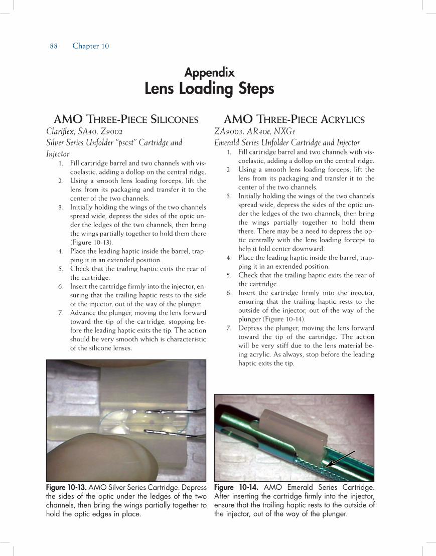
88 Chapter 10
amo three-piece siliconesClariflex, SA40, Z9002 Silver Series Unfolder “pscst” Cartridge and Injector 1. Fill cartridge barrel and two channels with vis-
coelastic, adding a dollop on the central ridge. 2. Using a smooth lens loading forceps, lift the
lens from its packaging and transfer it to the center of the two channels.
3. Initially holding the wings of the two channels spread wide, depress the sides of the optic un-der the ledges of the two channels, then bring the wings partially together to hold them there (Figure 10-13).
4. Place the leading haptic inside the barrel, trap-ping it in an extended position.
5. Check that the trailing haptic exits the rear of the cartridge.
6. Insert the cartridge firmly into the injector, en-suring that the trailing haptic rests to the side of the injector, out of the way of the plunger.
7. Advance the plunger, moving the lens forward toward the tip of the cartridge, stopping be-fore the leading haptic exits the tip. The action should be very smooth which is characteristic of the silicone lenses.
amo three-piece acrylics ZA9003, AR40e, NXG1 Emerald Series Unfolder Cartridge and Injector 1. Fill cartridge barrel and two channels with vis-
coelastic, adding a dollop on the central ridge. 2. Using a smooth lens loading forceps, lift the
lens from its packaging and transfer it to the center of the two channels.
3. Initially holding the wings of the two channels spread wide, depress the sides of the optic un-der the ledges of the two channels, then bring the wings partially together to hold them there. There may be a need to depress the op-tic centrally with the lens loading forceps to help it fold center downward.
4. Place the leading haptic inside the barrel, trap-ping it in an extended position.
5. Check that the trailing haptic exits the rear of the cartridge.
6. Insert the cartridge firmly into the injector, ensuring that the trailing haptic rests to the outside of the injector, out of the way of the plunger (Figure 10-14).
7. Depress the plunger, moving the lens forward toward the tip of the cartridge. The action will be very stiff due to the lens material be-ing acrylic. As always, stop before the leading haptic exits the tip.
AppendixLens Loading Steps
Figure 10-13. AMO Silver Series Cartridge. Depress the sides of the optic under the ledges of the two channels, then bring the wings partially together to hold the optic edges in place.
Figure 10-14. AMO Emerald Series Cartridge. After inserting the cartridge firmly into the injector, ensure that the trailing haptic rests to the outside of the injector, out of the way of the plunger.
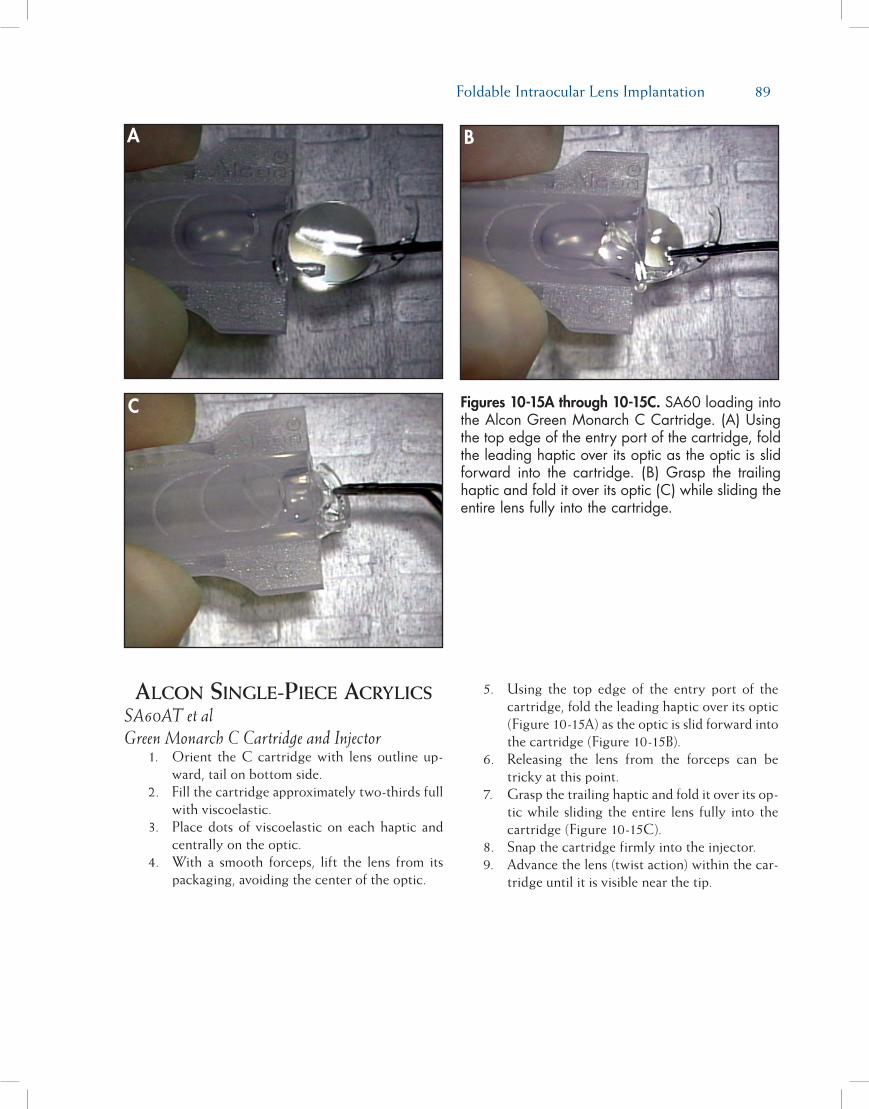
Foldable Intraocular Lens Implantation 89
alcon single-piece acrylics SA60AT et al Green Monarch C Cartridge and Injector 1. Orient the C cartridge with lens outline up-
ward, tail on bottom side. 2. Fill the cartridge approximately two-thirds full
with viscoelastic. 3. Place dots of viscoelastic on each haptic and
centrally on the optic. 4. With a smooth forceps, lift the lens from its
packaging, avoiding the center of the optic.
5. Using the top edge of the entry port of the cartridge, fold the leading haptic over its optic (Figure 10-15A) as the optic is slid forward into the cartridge (Figure 10-15B).
6. Releasing the lens from the forceps can be tricky at this point.
7. Grasp the trailing haptic and fold it over its op-tic while sliding the entire lens fully into the cartridge (Figure 10-15C).
8. Snap the cartridge firmly into the injector. 9. Advance the lens (twist action) within the car-
tridge until it is visible near the tip.
Figures 10-15A through 10-15C. SA60 loading into the Alcon Green Monarch C Cartridge. (A) Using the top edge of the entry port of the cartridge, fold the leading haptic over its optic as the optic is slid forward into the cartridge. (B) Grasp the trailing haptic and fold it over its optic (C) while sliding the entire lens fully into the cartridge.
A B
C
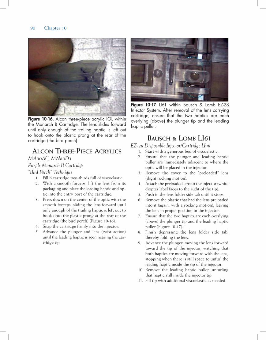
90 Chapter 10
alcon three-piece acrylics MA30AC, MN60D3 Purple Monarch B Cartridge “Bird Perch” Technique 1. Fill B cartridge two-thirds full of viscoelastic. 2. With a smooth forceps, lift the lens from its
packaging and place the leading haptic and op-tic into the entry port of the cartridge.
3. Press down on the center of the optic with the smooth forceps, sliding the lens forward until only enough of the trailing haptic is left out to hook onto the plastic prong at the rear of the cartridge (the bird perch) (Figure 10-16).
4. Snap the cartridge firmly into the injector. 5. Advance the plunger and lens (twist action)
until the leading haptic is seen nearing the car-tridge tip.
bausch & lomb li61 EZ-28 Disposable Injector/Cartridge Unit 1. Start with a generous bed of viscoelastic. 2. Ensure that the plunger and leading haptic
puller are immediately adjacent to where the optic will be placed in the injector.
3. Remove the cover to the “preloaded” lens (slight rocking motion).
4. Attach the preloaded lens to the injector (white diopter label faces to the right of the tip).
5. Push in the lens folder side tab until it stops. 6. Remove the plastic that had the lens preloaded
into it (again, with a rocking motion), leaving the lens in proper position in the injector.
7. Ensure that the two haptics are each overlying (above) the plunger tip and the leading haptic puller (Figure 10-17).
8. Finish depressing the lens folder side tab, thereby folding the lens.
9. Advance the plunger, moving the lens forward toward the tip of the injector, watching that both haptics are moving forward with the lens, stopping when there is still space to unfurl the leading haptic inside the tip of the injector.
10. Remove the leading haptic puller, unfurling that haptic still inside the injector tip.
11. Fill tip with additional viscoelastic as needed.
Figure 10-16. Alcon three-piece acrylic IOL within the Monarch B Cartridge. The lens slides forward until only enough of the trailing haptic is left out to hook onto the plastic prong at the rear of the cartridge (the bird perch).
Figure 10-17. LI61 within Bausch & Lomb EZ-28 Injector System. After removal of the lens carrying cartridge, ensure that the two haptics are each overlying (above) the plunger tip and the leading haptic puller.
91
Ophthalmic viscoelastic devices (OVDs) are fun-damental tools in modern cataract surgery. These materials coat and protect delicate intraocular tissues, maintain the relationships of ocular structures, cre-ate space, and improve visualization. The successful outcome of a difficult or complex cataract procedure often hinges on a surgeon’s knowledge of OVDs, and his or her ability to select the OVD or combination of OVDs that best meets the specific challenges of the case.
Understanding the clinical behavior of OVDs is actually quite simple. There are two key points. The first is that the physical properties and characteris-tics of OVDs are defined primarily by the molecular chain length of the material. The second is that these properties and characteristics change in a predictable fashion under different conditions of fluid movement within the eye. With a little basic knowledge, one can quickly learn to look at the package insert of any OVD and predict with a great deal of confidence how the material is likely to perform clinically.
In clinical terms, OVDs generally may be classi-fied either as “cohesive” or “dispersive” in character. Molecular chain length is the primary determinant of “cohesive” or “dispersive” clinical behavior.
Cohesive ophthalmiC visCoelastiC DeviCes
Cohesive OVDs such as Healon and Healon GV (AMO, Santa Ana, CA), Provisc (Alcon, Fort Worth, TX), Amvisc (Bausch & Lomb, Rochester, NY), and Staarvisc II (STAAR Surgical, Monrovia, CA) are high molecular weight, long-chained sodium hyal-uronate OVDs (range of molecular weight 1,000,000 to 7,000,000 Daltons). These high molecular weight OVDs are referred to as “cohesive” because their long molecular chains tends to interlock and intertwine. This causes the molecules of these OVDs to become entangled and behave intraocularly as a cohesive unit.
Dispersive ophthalmiC visCoelastiC DeviCes
Dispersive OVDs such as Healon D (AMO) and Viscoat (Alcon) are low molecular weight, short-chained sodium hyaluronate OVDs. The molecular weight of sodium hyaluronate for both Healon D and Viscoat is approximately 500,000 Daltons. Viscoat has an additional material, chondroitin sulfate, which has a molecular weight of approximately 25,000 Daltons. These low molecular weight OVDs are referred to as
Understanding the Clinical Behavior of Ophthalmic
Viscoelastic DevicesD. Michael Colvard, MD, FACS
Chapter11

92 Chapter 11
“dispersive” because their short molecular chains do not interlink or become entangled easily. This causes the molecules of these OVDs to separate from one another and behave in a dispersive manner.
Defining Zero shear vs high shear ConDitions
Cohesive and dispersive OVDs behave predict-ably under different conditions of fluid movement within the eye. Zero shear is a term used to describe a condition when there is no fluid movement within the eye. Capsulorrhexis performed in an anterior chamber filled with an OVD is an example of a zero shear con-dition. High shear describes a condition when there is a high rate of fluid movement within the eye. High shear conditions exist during phacoemulsification and during aspiration/irrigation.
ophthalmiC visCoelastiC DeviCe Behaviors at
Zero shear
Cohesive Ophthalmic Viscoelastic DevicesDuring conditions of zero shear, the long-chained
molecules of cohesive OVDs tend to intertwine and “lock in position.” This creates a scaffolding effect
intraocularly that helps these OVDs to maintain space very effectively. This quality makes cohesive OVDs more retentive when there is no fluid movement in the eye, and ideal for surgical challenges that require difficult intraocular maneuvers such as intraocular lens (IOL) exchanges. Higher molecular weight cohesive OVDs such as Healon (AMO) and Healon GV are more retentive than lower molecular weight cohesive OVDs such as Provisc (Figure 11-1A).
Dispersive Ophthalmic Viscoelastic DevicesThe short-chained molecules of dispersive OVDs
tend to slide over one another and create a puddle under conditions of zero shear. The concentrations of dispersive low molecular weight OVDs are gener-ally higher (range ~3% to 4%) than that of cohesive longer chained OVDs (range ~1% to 2.3%). The concentration is increased in an effort to increase the zero shear viscosity of these shorter chained materials. An increase in concentration increases to some degree the retentiveness of short-chained OVDs and prevents these materials from being excessively “runny.” In gen-eral, however, dispersive OVDs are not as effective as cohesive materials at maintaining surgical space under conditions of zero shear (Figure 11-1B).
Figure 11-1A. Cohesive OVDs behave like jelly or jam under conditions of zero shear (when there is no fluid movement in the eye). The long-chained molecules of cohesive OVDs tend to intertwine and “lock in position.” This creates a scaffolding effect intraocularly that helps these OVDs to maintain space very effectively.
Figure 11-1B. Dispersive OVDs behave like honey at zero shear. The short-chained molecules of dis-persive OVDs tend to slide over one another and puddle. In general, dispersive OVDs are good at coating intraocular structures but are not as effec-tive as cohesive materials at maintaining surgical space.

Understanding the Clinical Behavior of Ophthalmic Viscoelastic Devices 93
ophthalmiC visCoelastiC DeviCe Behaviors at
high shear
Cohesive Ophthalmic Viscoelastic DevicesThe long-chained molecules of cohesive OVDs,
under conditions of high shear, tend to entangle and leave the eye as a bolus. This makes cohesive materials much easier to remove at the conclusion of a proce-dure, but less protective than dispersive OVDs during phacoemulsification (Figure 11-2A).
Dispersive Ophthalmic Viscoelastic DevicesDispersive OVDs of sodium hyaluronate provide
superior endothelial protection during phacoemulsi-fication. The short-chained molecules tend to slide over themselves and coat intraocular structures in a honey-like fashion. In addition, because the short-chained molecules do not tend to interlink, dispersive OVDs tend to stay in the anterior chamber much more effectively during phacoemulsification than cohesive OVDs. This dispersive quality, however, ceases to be an asset when it is time to remove the viscoelas-tic material at the end of a case. Complete removal of sodium hyaluronate dispersive OVDs is difficult because the molecules do not tend to join together and do not aspirate as a unit (Figure 11-2B).
the aDvantages of Using Dispersive anD Cohesive
ophthalmiC visCoelastiC DeviCes together
Many surgeons, in order to obtain the best quali-ties of both dispersive and cohesive OVDs, use the two types of OVDs in combination. A dispersive OVD, such as Healon D, may be used at the beginning of a case to provide maximum endothelial protection during phacoemulsification. A cohesive OVD, such as Healon, may then be used at the time of IOL implan-tation both to provide excellent chamber maintenance and easy removal of the OVD, thereby reducing the chances of elevated intraocular pressure (IOP) post-operatively.
the speCial QUalities of healon 5
Healon 5 is an unusual OVD that cannot be described adequately as either a cohesive or a disper-sive agent. Depending on conditions of flow, it has qualities of both. Healon 5 has both a high molecu-lar weight (4,000,000 Daltons) and a relatively high molecular concentration (2.3%).
At zero shear, the long-chained molecules of Healon 5 lock together readily and act as a unit once
Figure 11-2A. Long-chained molecules of cohesive OVDs behave like spaghetti during conditions of high shear. They tend to entangle and leave the eye as a bolus. This makes cohesive materials much easier to remove at the conclusion of a procedure.
Figure 11-2B. Short-chained molecules of dispersive OVDs under conditions of high shear behave like penne. The molecules do not tend to interlink and stay in the anterior chamber much more effectively than do cohesive OVDs. For this reason, dispersive OVDs of sodium hyaluronate provide superior endothelial protection in conditions of high shear, especially during phacoemulsification.

94 Chapter 11
they are injected into the anterior chamber. The link-age of the long-chained molecules is enhanced by increased concentration of the material. As a result, Healon 5 is the most highly retentive of all OVDs at zero shear, allowing this material not only to maintain anterior chamber volume extraordinarily well but to move tissue and enlarge poorly dilating pupils as well.
Under conditions of low shear, when phaco-emulsification parameters are set to low flow and low vacuum, the Healon 5 material can be fractured and compartmentalized. An arching dome of Healon 5 can be left above the pupillary plane which provides both endothelial protection and pupillary dilatation, while nucleus removal is accomplished in the posterior chamber.
During irrigation/aspiration, high shear conditions may be created by increasing both flow and vacuum, and Healon 5 becomes a super cohesive material that leaves the anterior chamber readily in a bolus. Special care must also be taken at the end of the case to remove all of the high molecular weight Healon 5 from beneath the IOL in order to prevent an elevation of IOP. Because of its unique clinical features, Healon 5 is very useful in the management of some of the most difficult challenges in cataract surgery, including small pupils unresponsive to mydriatics, iris prolapse, floppy iris syndrome, and the mature intumescent cataract. To understand the clinical applications of Healon 5 more completely, see Chapter 7 for a detailed descrip-tion of its uses and indications.

95
Several different factors come into play when it comes to choosing an intraocular lens (IOL) for cata-ract surgery. On the one hand, materials and design should result in a low degree of postoperative inflam-mation by being as inert as possible and have a good track record concerning long-term complications such as posterior capsule opacification (PCO), and on the other hand, also be easy to handle concerning folding and implantation. Also, the production process for the manufacturer should be relatively simple to make it affordable. In special cases, such as those with incom-plete capsule support, high myopia, or with a history of uveitis, the IOL choice may differ from the usual one. Additionally, in eyes with a cornea that either has astigmatism and/or spherical aberrations (SA), special IOLs may be indicated. Last but not least, patients who want to be less dependent on spectacles for near work or intermediate distance vision after surgery may be candidates for multifocal IOL designs.
This chapter will first focus on the different materi-als and designs available, then on the clinical outcomes relevant to IOLs, such as postoperative inflammation and PCO, and some of the criteria important for choos-ing an IOL for the individual patient.
Intraocular lens MaterIalsThe earliest IOLs were made of polymethylmeth-
acrylate (PMMA), the plastic that IOL inventor Harold Ridley had noticed to be inert in eyes of World War II aviators struck by flying plastic during combat. With the introduction of phacoemulsification and the possi-bility to remove the cataract through smaller incisions, foldable materials were developed for IOLs such as hydrophobic acrylic, hydrophilic acrylic (or hydrogel), and hydrophobic silicone, the three main material groups in use today (Figure 12-1).
Hydrophobic Acrylic
PolymethylmethacrylateEven though the use of nonfoldable PMMA for cat-
aract surgery today plays little role in the United States and Europe mainly because of large wound size, it still plays an important role in countries where extracapsu-lar cataract extraction (ECCE) with manual expression of the nucleus is the technique of choice. PMMA IOLs with a sharp optic edge have been shown to result in relatively low PCO rates,1,2 and heparin-surface modi-fied PMMA IOLs have been used in uveitis patients with good results.3 Currently, PMMA is still used for sulcus-placed IOLs due to their overall rigidity, which
Intraocular Lens Materials and Design
Oliver Findl, MD, MBA
Chapter12
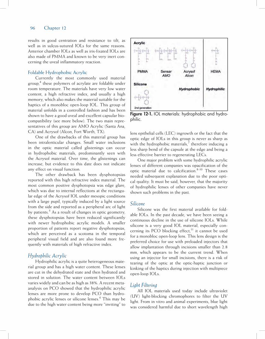
96 Chapter 12
results in good centration and resistance to tilt, as well as in sulcus-sutured IOLs for the same reasons. Anterior chamber IOLs as well as iris-fixated IOLs are also made of PMMA and known to be very inert con-cerning the uveal inflammatory reaction.
Foldable Hydrophobic AcrylicCurrently the most commonly used material
group,4 these polymers of acrylate are foldable under room temperature. The materials have very low water content, a high refractive index, and usually a high memory, which also makes the material suitable for the haptics of a monobloc open-loop IOL. This group of material unfolds in a controlled fashion and has been shown to have a good uveal and excellent capsular bio-compatibility (see more below). The two main repre-sentatives of this group are AMO Acrylic (Santa Ana, CA) and Acrysof (Alcon, Fort Worth, TX).
One of the drawbacks of this material group has been intralenticular changes. Small water inclusions in the optic material called glistenings can occur in hydrophobic materials, predominantly seen with the Acrysof material. Over time, the glistenings can increase, but evidence to this date does not indicate any effect on visual function.
The other drawback has been dysphotopsias reported with this high refractive index material. The most common positive dysphotopsia was edge glare, which was due to internal reflections at the rectangu-lar edge of the Acrysof IOL under mesopic conditions with a large pupil, typically induced by a light source from the side and reported as a peripheral arc of light by patients.5 As a result of changes in optic geometry, these dysphotopsias have been reduced significantly with newer hydrophobic acrylic models. A smaller proportion of patients report negative dysphotopsias, which are perceived as a scotoma in the temporal peripheral visual field and are also found more fre-quently with materials of high refractive index.
Hydrophilic AcrylicHydrophilic acrylic is a quite heterogeneous mate-
rial group and has a high water content. These lenses are cut in the dehydrated state and then hydrated and stored in solution. The water content between IOLs varies widely and can be as high as 38%. A recent meta-analysis on PCO showed that the hydrophilic acrylic lenses are more prone to develop PCO than hydro-phobic acrylic lenses or silicone lenses.6 This may be due to the high water content being more “inviting” to
lens epithelial cells (LEC) ingrowth or the fact that the optic edge of IOLs in this group is never as sharp as with the hydrophobic materials,7 therefore inducing a less sharp bend of the capsule at the edge and being a less effective barrier to regenerating LECs.
One major problem with some hydrophilic acrylic lenses of different companies was opacification of the optic material due to calcification.8-10 These cases needed subsequent explanation due to the poor opti-cal quality. It must be said, however, that the majority of hydrophilic lenses of other companies have never shown such problems in the past.
Silicone Silicone was the first material available for fold-
able IOLs. In the past decade, we have been seeing a continuous decline in the use of silicone IOLs. While silicone is a very good IOL material, especially con-cerning its PCO blocking effect,11 it cannot be used for a monobloc open-loop lens. This lens design is the preferred choice for use with preloaded injectors that allow implantation through incisions smaller than 2.8 mm, which appears to be the current trend. When using an injector for small incisions, there is a risk of tearing of the optic at the optic-haptic junction or kinking of the haptics during injection with multipiece open-loop IOLs.
Light FilteringAll IOL materials used today include ultraviolet
(UV) light-blocking chromophores to filter the UV light. From in vitro and animal experiments, blue light was considered harmful due to short wavelength high
Figure 12-1. IOL materials: hydrophobic and hydro-philic.

Intraocular Lens Materials and Design 97
energy light causing retinal damage by inducing more oxidative stress at the retinal level. Even though this has not been shown or proven in humans, some manufac-turers have introduced yellow-tinted IOLs to filter the short wavelength light. A yellow lens has two potential drawbacks: one is a reduction in color contrast sensitiv-ity, especially under mesopic conditions, and another is that the melatonin production in the brain may be altered, causing a change in the circadian rhythms that are steered by blue light levels in the eye.12
Although to date no study has shown that a yellow lens causes a significant loss in color contrast sensitiv-ity, this may also be due to the lack of sensitivity of the psychophysical tests used. From my own experience, I have two patients who could clearly identify the eye with the yellow lens from the eye that had a standard fully transparent non-yellow lens. They described the vision with the yellow lens eye as a little “dirtier” than the other. Clinically, yellow lenses have not been shown to be protective, and the possible drawbacks may contribute to surgeons being somewhat hesitant to implant yellow lenses on a routine basis in patients with no increased risk to develop macula problems.
Intraocular lens DesIgnDesign options for IOLs currently are manifold:
multipiece or monobloc; plate or open-loop style; angulated or planar haptics; special haptics for certain indications such as sulcus, anterior chamber angle, or iris fixation; optic shape and edge design; and optic geometry for certain indications such as toric, aspher-ic, or multifocal IOLs (Figure 12-2).
Plate HapticOne of the first foldable IOLs was a silicone plate
haptic IOL (see Figure 12-2). Today, several manufac-turers of hydrophilic IOLs still use a plate-style design, usually combined with small loop-like haptics at the four corners to allow better adaptation to capsule bag size. One major drawback of the plate-style design is the incomplete fusion of the anterior and posterior capsule leaves along the plate haptic axis and, there-fore, the lack of capsule bending at the optic edge. This allows LECs to migrate centrally onto the pos-terior capsule and cause the most common long-term problem after cataract surgery—PCO.
Some manufacturers have designed a cross-over between plate haptic and open-loop haptic design (see Figure 12-2). This allows better adaptability to capsule bag size variations and also reduces the zone of missing capsule bend.
Open-Loop
MultipieceOpen-loop IOLs are held in place in the capsule
bag by exerting a centripetal pressure on the capsule bag fornix and sometimes also the ciliary body, or in case of sulcus placement the ciliary sulcus. The haptics of an IOL should maintain their original configura-tion during the implantation procedure. The haptic rigidity, which is the resistance of the haptic to forces that bend the loops centrally, and the haptic memory, which is the ability of the haptic to go back to its origi-nal configuration after having been bent, are the two factors that determine whether an IOL will center well in an eye after implantation. Additionally, the contrac-tive forces of the shrinking capsule bag due to fibrosis, especially in cases with zonule weakness or asymmet-ric shrinking, will need counteracting pressure from the haptics to ensure good centration.
Haptic materials are most commonly PMMA, and then polyvinylidene fluoride (PVDF), polyimide (elas-timide), and polypropylene (prolene) (Figure 12-3). The prolene haptic material, however, has a lower memory than the other three materials13 and is used less fre-quently due to recurrent problems of decentration.
Concerning haptic shape, the j-loop design results in pinpointed contact with the capsule bag equator. This may lead to stress folds of the posterior capsule, which usually disappear within the first months after surgery concomitant with the decrease in memory of the haptic material. This type of loop is the preferred type for IOLs dedicated for sulcus placement.
Single-PieceNew manufacturing methods led to the introduc-
tion of single-piece open-loop IOLs some years ago. Unlike three-piece IOLs, which usually consist of two different materials (optic and haptics) and need to be assembled by hand, these IOLs are produced in a single step from one material. Single-piece IOLs tend to be more resistant to damage when used with injectors and the production process is cheaper since less staff intensive. However, most single-piece designs feature broad haptic shoulders at the transition to the IOL optic for stability reasons (see Figure 12-3). This raises the question whether these lenses may have less of a PCO-inhibiting effect because of the incomplete sharp posterior optic rim. Nevertheless, clinical tri-als (some of them still ongoing) did not show sig-nificant differences in PCO rates between single-piece and multipiece IOLs (Figure 12-4).14,15 However, the

98 Chapter 12
interrupted sharp optic rim might lead to problems in new ultrathin single-piece IOLs developed for micro-incisional surgery. Next-generation one-piece IOLs, such as the Tecnis 1-Piece IOL, incorporate a 360-degree square-edge design.
Haptic AngulationThe PCO preventative effect of sharp-edge optics
suggests that it might be useful to maximize the bar-rier effect to migrating LECs at the posterior optic edge by pushing the IOL backward against the pos-terior capsule. This can be achieved with angulated
Figure 12-2.

Intraocular Lens Materials and Design 99
haptic designs (see Figure 12-2). They were originally introduced because an angulation reduced iris shave in cases where the lens was placed in the sulcus. Consequently, such posterior vaulting characteris-tics can be found in many modern three-piece IOLs, with angulation of 5 to 10 degrees. However, studies showed that these designs do not lead to a smaller IOL to posterior capsule distance16 and do not seem to have a better PCO-inhibiting effect than IOLs with little or no haptic angulation.
Intraocular Lens Overall LengthEven though the average capsule bag only has a
diameter of about 10.4 mm,17 the variability is quite large with size ranging from 9.8 to 10.9 mm. For this reason and the fact that the bag ovalizes after lens implantation, especially in the case of weak zonules,
most IOLs are oversized for the bag. This is especially true for the multipiece IOLs from the major manufac-turers, which usually have an overall length of 13 mm. It appears that the main reason for such oversizing is the need for the IOL to also be suitable for sulcus placement, even though a larger diameter would be preferable for this occasion.
Intraocular lenses for InsuffIcIent capsule support
In the case of capsule complications where a bag placement of an IOL is no longer possible, but the anterior capsule is intact, the IOL can be placed with the haptics in the sulcus. However, in order to ensure centration and axial stability of the IOL, an overall length (haptic to haptic) of at least 13 mm should be chosen. Optimally, especially in eyes with a larger sulcus diameter such as myopic eyes, 13.5 or 14 mm would be more appropriate. There are some dedicated sulcus IOLs with such overall length often combined with a larger optic diameter of 6.5 or even 7 mm, both available as nonfoldable PMMA or foldable IOLs (see Figure 12-2). Foldable single-piece IOLs should be avoided for these situations as their relatively thick haptics can cause rubbing on the posterior aspect of the iris with pigment dispersion.
In cases where the rhexis is still fully intact, a positioning of the optic through the rhexis and behind the anterior capsule (posterior buttonholing) ensures a good centration of the IOL and results in an axial position of the optic close to that of bag placement, therefore, only requiring a small to no adjustment
Figure 12-3. Fusion of capsule at haptic-optic junction for different haptic designs. (Left) Acrysof multi-piece with nearly complete fusion. (Middle) Acrysof single-piece with incomplete fusion which may serve as one entry site (arrows) for regenerating LECs and no sharp edge at junction. (Right) The Tecnis 1-Piece IOL incorporates a new feature of the ProTec 360-degree barrier edge.
Figure 12-4. Both eyes of same patient 3 years after surgery. (Left) Single-piece Acrysof IOL with ingrowth of LECs mainly at optic-haptic junction. (Right) Multipiece Acrysof IOL with little ingrowth of LECs at similar location.
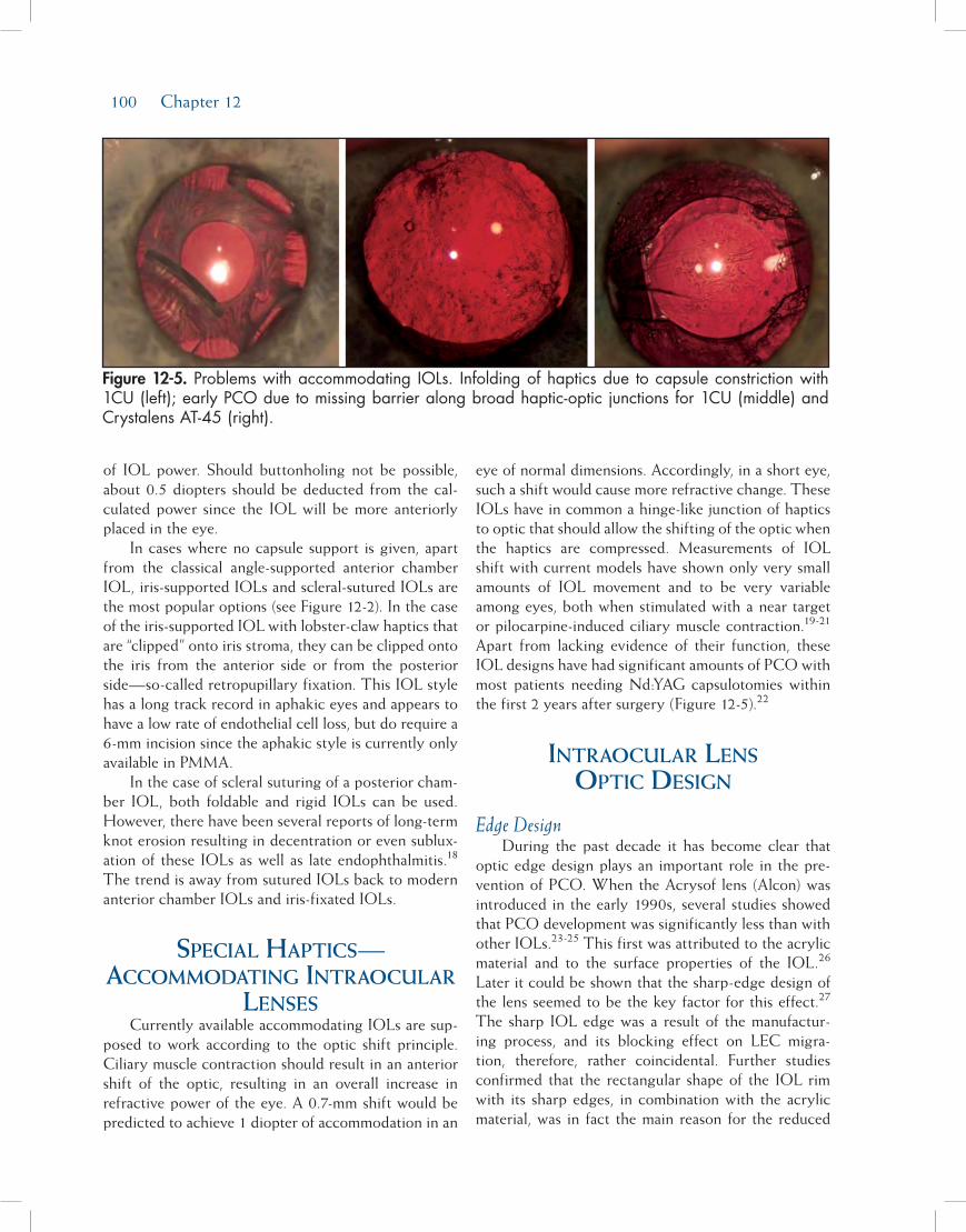
100 Chapter 12
of IOL power. Should buttonholing not be possible, about 0.5 diopters should be deducted from the cal-culated power since the IOL will be more anteriorly placed in the eye.
In cases where no capsule support is given, apart from the classical angle-supported anterior chamber IOL, iris-supported IOLs and scleral-sutured IOLs are the most popular options (see Figure 12-2). In the case of the iris-supported IOL with lobster-claw haptics that are “clipped” onto iris stroma, they can be clipped onto the iris from the anterior side or from the posterior side—so-called retropupillary fixation. This IOL style has a long track record in aphakic eyes and appears to have a low rate of endothelial cell loss, but do require a 6-mm incision since the aphakic style is currently only available in PMMA.
In the case of scleral suturing of a posterior cham-ber IOL, both foldable and rigid IOLs can be used. However, there have been several reports of long-term knot erosion resulting in decentration or even sublux-ation of these IOLs as well as late endophthalmitis.18 The trend is away from sutured IOLs back to modern anterior chamber IOLs and iris-fixated IOLs.
specIal HaptIcs— accoMMoDatIng Intraocular
lensesCurrently available accommodating IOLs are sup-
posed to work according to the optic shift principle. Ciliary muscle contraction should result in an anterior shift of the optic, resulting in an overall increase in refractive power of the eye. A 0.7-mm shift would be predicted to achieve 1 diopter of accommodation in an
eye of normal dimensions. Accordingly, in a short eye, such a shift would cause more refractive change. These IOLs have in common a hinge-like junction of haptics to optic that should allow the shifting of the optic when the haptics are compressed. Measurements of IOL shift with current models have shown only very small amounts of IOL movement and to be very variable among eyes, both when stimulated with a near target or pilocarpine-induced ciliary muscle contraction.19-21 Apart from lacking evidence of their function, these IOL designs have had significant amounts of PCO with most patients needing Nd:YAG capsulotomies within the first 2 years after surgery (Figure 12-5).22
Intraocular lens optIc DesIgn
Edge DesignDuring the past decade it has become clear that
optic edge design plays an important role in the pre-vention of PCO. When the Acrysof lens (Alcon) was introduced in the early 1990s, several studies showed that PCO development was significantly less than with other IOLs.23-25 This first was attributed to the acrylic material and to the surface properties of the IOL.26 Later it could be shown that the sharp-edge design of the lens seemed to be the key factor for this effect.27 The sharp IOL edge was a result of the manufactur-ing process, and its blocking effect on LEC migra-tion, therefore, rather coincidental. Further studies confirmed that the rectangular shape of the IOL rim with its sharp edges, in combination with the acrylic material, was in fact the main reason for the reduced
Figure 12-5. Problems with accommodating IOLs. Infolding of haptics due to capsule constriction with 1CU (left); early PCO due to missing barrier along broad haptic-optic junctions for 1CU (middle) and Crystalens AT-45 (right).

Intraocular Lens Materials and Design 101
formation of PCO.28 Studies by Nishi revealed that the discontinuous capsular bend seems to be a key factor for the preventative effect of a sharp-edge optic.27,29 The capsular bend at the posterior optic edge causes mechanical pressure and/or contact inhibition of LEC growth on the posterior capsule (Figure 12-6).
As a result of these findings, several new IOLs with a sharp optic edge design were introduced in the past years and compared in clinical trials. In a meta-analysis of the randomized controlled trials comparing round and sharp-edge IOLs,30 there was a clear beneficial effect of sharp-edge IOLs concerning inhibition of PCO. This also confirmed that the sole modification of the posterior optic edge from a round edge to a sharp edge leads to a significant reduction of PCO by inducing a discontinuous bend at the posterior capsule (Figure 12-7).31,32
Unfortunately, sharp optic edges of IOLs may also have disadvantages. As described previously, in some cases with implantation of lenses with a rectangular edge shape combined with a high refractive index, such as found with the Acrysof lens, an increased incidence of persistent edge-glare phenomena was reported.33,34 Sharp-edge IOL designs cause the light rays that are refracted through the peripheral IOL to be more intense on the peripheral retina. Round-edge IOL designs disperse the rays of light over a larger sur-face area of the retina, leading to less glare. However, the half-rounded edge profile of some newly developed IOLs with a round anterior and sharp posterior optic edge seems to avoid this disturbing side effect.35
Optic Geometry
BiconvexityMost IOLs on the market have a symmetrically
biconvex optic, meaning that the radius of curvature
of the front and back surface are identical. Some manufacturers have an asymmetric biconvex optic, where the back surface curvature is relatively flat and constant throughout most of the power range and the anterior curvature is varied for IOL power. This causes a slight shift of the principal optical plane of the IOL and also implies that the lens should not be implanted front to back in the eye, apart from the angulation of the haptics being backward as well. In a symmetrically biconvex lens with no angulation, the IOL could be implanted front to back without a change in optical power.
Optical ZoneMost IOLs have a full-size effective optical zone
of 6 mm in the main range of IOL powers. Therefore, the higher powered IOLs will have a thicker optic than the lower powers. This has the advantage of a full optic zone, but can make folding of the IOL or injecting with a shooter variable depending on IOL power. Some IOLs keep a constant center thick-ness of the optic and vary the effective optical zone, thereby varying the curvature of the optic and, there-fore, optic power. To my knowledge, there was only one manufacturer (Dr. Schmidt) that actually varied refractive index of the silicone material used for dif-ferent powers, thereby keeping a constant effective optical zone and center thickness.
Special Optics
Aspherical Intraocular LensesThis topic is covered extensively in Chapter 13.
In short, these IOLs are either neutral concerning SA, therefore not adding SA to the eye, or like most models currently on the market have a prolate sur-face inducing negative SA, which should neutralize
Figure 12-6. Blocking of LEC migration at posterior sharp optic edge due to bending of the capsule (left) compared to round edge IOL (right).

102 Chapter 12
the positive SA of the average cornea. The aim is to increase contrast sensitivity under mesopic conditions where the pupil is dilated. The IOLs have little to no effect when the pupil is small.
Toric Intraocular LensesWith cataract surgery we can attempt to reduce
preexisiting corneal astigmatism using incisional tech-niques, such as placing the corneal incision on the
steep axis, adding an opposite clear cornea incision (OCCI) on the same axis, or making limbal relaxing incisions (LRIs) on the steep axis. Most surgeons will use a 600-micron knife to perform LRIs. LRIs are able to reduce corneal astigmatism by as much as 3 diop-ters. This topic is covered at length in Chapter 16. The variability of the outcome is mainly due to interpatient differences in scarring of the corneal tissue, corneal rigidity, and corneal thickness.
Figure 12-7. PCO 1 year (upper) and 3 years (lower) after surgery for round (left) and sharp (right) edge optic design for a hydrophobic acrylic IOL.
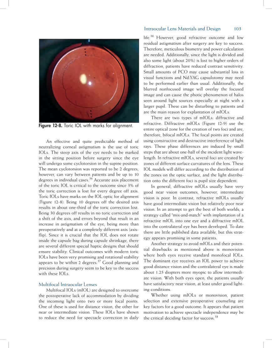
Intraocular Lens Materials and Design 103
An effective and quite predictable method of neutralizing corneal astigmatism is the use of toric IOLs. The steep axis of the eye needs to be marked in the sitting position before surgery since the eye will undergo some cyclotorsion in the supine position. The mean cyclotorsion was reported to be 2 degrees, however, can vary between patients and be up to 10 degrees in individual cases.36 Accurate axis placement of the toric IOL is critical to the outcome since 3% of the toric correction is lost for every degree off axis. Toric IOLs have marks on the IOL optic for alignment (Figure 12-8). Being 10 degrees off the desired axis results in about one-third of the toric correction lost. Being 30 degrees off results in no toric correction and a shift of the axis, and errors beyond that result in an increase in astigmatism of the eye, being more than preoperatively and at a completely different axis (axis-flip). Since it is crucial that the IOL does not rotate inside the capsule bag during capsule shrinkage, there are several different special haptic designs that should ensure stability. Clinical outcomes with modern toric IOLs have been very promising and rotational stability appears to be within 2 degrees.37 Good planning and precision during surgery seem to be key to the success with these IOLs.
Multifocal Intraocular LensesMultifocal IOLs (mIOL) are designed to overcome
the postoperative lack of accommodation by dividing the incoming light onto two or more focal points. One of these is used for distance vision, the other for near or intermediate vision. These IOLs have shown to reduce the need for spectacle correction in daily
life.38 However, good refractive outcome and low residual astigmatism after surgery are key to success. Therefore, meticulous biometry and power calculation are needed. Additionally, since the light is divided and also some light (about 20%) is lost to higher orders of diffraction, patients have reduced contrast sensitivity. Small amounts of PCO may cause substantial loss in visual functions and Nd:YAG capsulotomy may need to be performed earlier than usual. Additionally, the blurred nonfocused image will overlay the focused image and can cause the photic phenomenon of halos seen around light sources especially at night with a larger pupil. These can be disturbing to patients and are the main reason for explantation of mIOLs.
There are two types of mIOLs: diffractive and refractive. Diffractive mIOLs (Figure 12-9) use the entire optical zone for the creation of two foci and are, therefore, bifocal mIOLs. The focal points are created using constructive and destructive interference of light rays. These phase differences are induced by small steps that are about one-half of the incident light wave-length. In refractive mIOLs, several foci are created by zones of different surface curvatures of the lens. These IOL models will differ according to the distribution of the zones on the optic surface, and the light distribu-tion onto the different foci is pupil size dependent.
In general, diffractive mIOLs usually have very good near vision outcomes, however, intermediate vision is poor. In contrast, refractive mIOLs usually have good intermediate vision but relatively poor near vision. In an attempt to get the best of both worlds, a strategy called “mix-and-match” with implantation of a refractive mIOL into one eye and a diffractive mIOL into the contralateral eye has been developed. To date there are little published data available, but this strat-egy appears promising in some patients.
Another strategy to avoid mIOLs and their poten-tial drawbacks as mentioned above is monovision where both eyes receive standard monofocal IOLs. The dominant eye receives an IOL power to achieve good distance vision and the contralateral eye is made about 1.25 diopters more myopic to allow intermedi-ate vision. With both eyes open, the patients usually have satisfactory near vision, at least under good light-ing conditions.
Whether using mIOLs or monovision, patient selection and extensive preoperative counseling are key factors for a good outcome. It appears that patient motivation to achieve spectacle independence may be the critical deciding factor for success.38
Figure 12-8. Toric IOL with marks for alignment.

104 Chapter 12
clInIcal perforMance of an Intraocular lens
BiocompatibilityPhacoemulsification and foldable IOL technology
have permitted the use of small incisions, which results in less trauma caused by cataract surgery. Immediate postoperative inflammation is mainly attributed to surgical irritation of the anterior uvea, which causes changes in the blood-aqueous barrier.39 Long-term postoperative inflammation is caused by other factors such as immunological reactions.
The performance of an IOL is determined by sev-eral factors such as the surgical technique,40 the peri-operative treatment,41 the IOL biomaterial and design, and the host reaction to the lens.
The cellular reaction seen on an IOL is an impor-tant indicator of the IOL’s biocompatibility. On the one hand, it consists of macrophages in the form of small, round cells and foreign body giant cell on the IOL surface. On the other hand, the cells are LECs after the capsule comes into contact with the foreign body IOL. Accordingly, the biocompatibility of an IOL can be divided into two parts—the uveal and the capsular reaction, as described by Amon.42
Uveal biocompatibility is defined as the reaction of the uvea to the IOL. As a result to the surgical trau-ma and the IOL, monocytes and macrophages migrate through the uvea’s vessel walls into the aqueous and then onto the IOL surface. Monocytes transform into small, round cells and macrophages transform into epithelioid and foreign body giant cells that are responsible for the phagocytosis of debris. These cells constitute the natural immunological process in a for-eign body reaction.
Capsular biocompatibility is defined as the reac-tion of LECs and the capsule to the IOL material and design. This encompasses LEC ongrowth, anterior capsule opacification, and PCO. The LECs residing on the posterior side of the anterior capsule (Figure 12-10), the so-called A-cells, can proliferate onto the IOL optic from the anterior capsular rim (ongrowth) and lay down collagen which results in whitening of the capsule as well as contraction of the capsule, which in turn may cause rhexis contraction or even phimosis, decentration of the IOL, or buttonholing of the IOL (Figure 12-11).
LECs also express cytokines, such as interleukin-1, interleukin-6, and transforming growth factor , that are responsible for LEC proliferation and transdiffer-
entiation into myofibroblasts and the synthesis of col-lagen fibers.43 These cytokines may act in an autocrine and paracrine fashion, influencing the postoperative proliferation of LECs in the capsular bag. Thus, Nishi and coauthors postulated that fibrous proliferation of LECs with anterior capsule fibrosis is often associated with blood-aqueous barrier disruption, clinically vis-ible as flare in the anterior chamber.43
posterIor capsule opacIfIcatIon
PCO (or after cataract) remains a common prob-lem after cataract surgery with implantation of an IOL. It resulted from the transition from intracapsular cata-ract extraction (ICCE) to ECCE, where the posterior lens capsule is left intact during surgery. Patients with PCO suffer from decreased visual acuity, impaired contrast sensitivity, and glare disability.
Clinically, two different components of PCO can be differentiated, namely a regeneratory and a fibrotic component (Figure 12-12). Regeneratory PCO is much more common; it is caused by residual LECs from the lens equator region, the so-called E-cells, migrating and proliferating into the space between the posterior capsule and the IOL, forming layers of lens material and Elschnig pearls. Fibrotic PCO is caused by LECs from the anterior capsule that undergo transforma-tion to myofibroblasts and gain access to the poste-rior capsule, causing whitening and wrinkling of the
Figure 12-9. Diffractive mIOL with PCO.
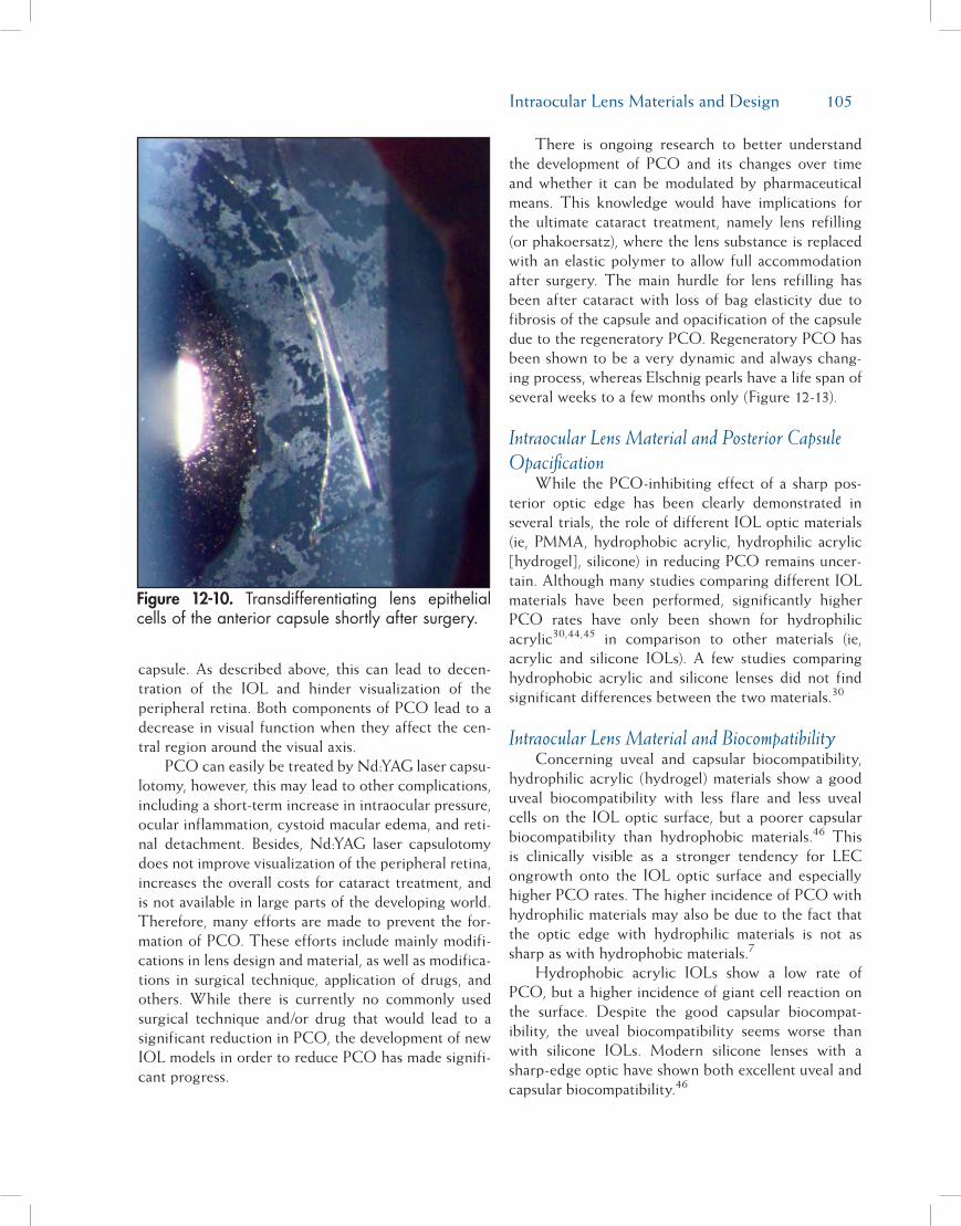
Intraocular Lens Materials and Design 105
capsule. As described above, this can lead to decen-tration of the IOL and hinder visualization of the peripheral retina. Both components of PCO lead to a decrease in visual function when they affect the cen-tral region around the visual axis.
PCO can easily be treated by Nd:YAG laser capsu-lotomy, however, this may lead to other complications, including a short-term increase in intraocular pressure, ocular inflammation, cystoid macular edema, and reti-nal detachment. Besides, Nd:YAG laser capsulotomy does not improve visualization of the peripheral retina, increases the overall costs for cataract treatment, and is not available in large parts of the developing world. Therefore, many efforts are made to prevent the for-mation of PCO. These efforts include mainly modifi-cations in lens design and material, as well as modifica-tions in surgical technique, application of drugs, and others. While there is currently no commonly used surgical technique and/or drug that would lead to a significant reduction in PCO, the development of new IOL models in order to reduce PCO has made signifi-cant progress.
There is ongoing research to better understand the development of PCO and its changes over time and whether it can be modulated by pharmaceutical means. This knowledge would have implications for the ultimate cataract treatment, namely lens refilling (or phakoersatz), where the lens substance is replaced with an elastic polymer to allow full accommodation after surgery. The main hurdle for lens refilling has been after cataract with loss of bag elasticity due to fibrosis of the capsule and opacification of the capsule due to the regeneratory PCO. Regeneratory PCO has been shown to be a very dynamic and always chang-ing process, whereas Elschnig pearls have a life span of several weeks to a few months only (Figure 12-13).
Intraocular Lens Material and Posterior Capsule Opacification
While the PCO-inhibiting effect of a sharp pos-terior optic edge has been clearly demonstrated in several trials, the role of different IOL optic materials (ie, PMMA, hydrophobic acrylic, hydrophilic acrylic [hydrogel], silicone) in reducing PCO remains uncer-tain. Although many studies comparing different IOL materials have been performed, significantly higher PCO rates have only been shown for hydrophilic acrylic30,44,45 in comparison to other materials (ie, acrylic and silicone IOLs). A few studies comparing hydrophobic acrylic and silicone lenses did not find significant differences between the two materials.30
Intraocular Lens Material and BiocompatibilityConcerning uveal and capsular biocompatibility,
hydrophilic acrylic (hydrogel) materials show a good uveal biocompatibility with less flare and less uveal cells on the IOL optic surface, but a poorer capsular biocompatibility than hydrophobic materials.46 This is clinically visible as a stronger tendency for LEC ongrowth onto the IOL optic surface and especially higher PCO rates. The higher incidence of PCO with hydrophilic materials may also be due to the fact that the optic edge with hydrophilic materials is not as sharp as with hydrophobic materials.7
Hydrophobic acrylic IOLs show a low rate of PCO, but a higher incidence of giant cell reaction on the surface. Despite the good capsular biocompat-ibility, the uveal biocompatibility seems worse than with silicone IOLs. Modern silicone lenses with a sharp-edge optic have shown both excellent uveal and capsular biocompatibility.46
Figure 12-10. Transdifferentiating lens epithelial cells of the anterior capsule shortly after surgery.
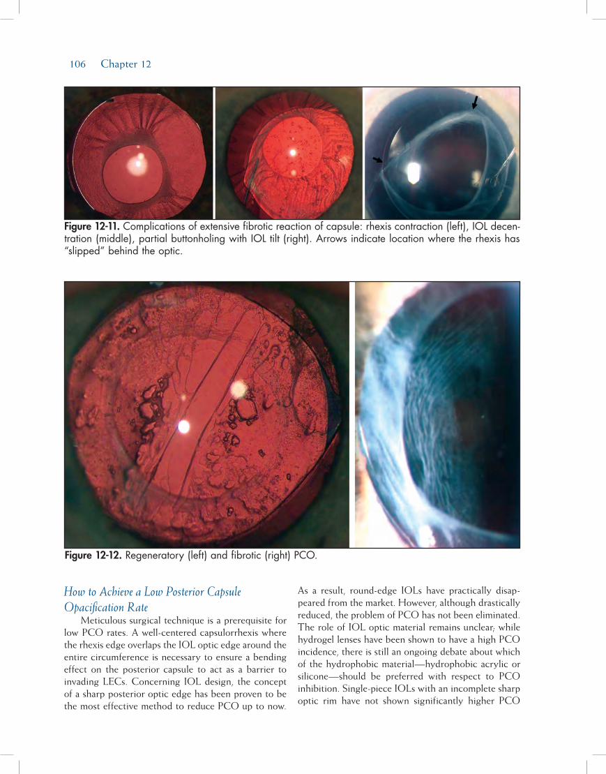
106 Chapter 12
How to Achieve a Low Posterior Capsule Opacification Rate
Meticulous surgical technique is a prerequisite for low PCO rates. A well-centered capsulorrhexis where the rhexis edge overlaps the IOL optic edge around the entire circumference is necessary to ensure a bending effect on the posterior capsule to act as a barrier to invading LECs. Concerning IOL design, the concept of a sharp posterior optic edge has been proven to be the most effective method to reduce PCO up to now.
As a result, round-edge IOLs have practically disap-peared from the market. However, although drastically reduced, the problem of PCO has not been eliminated. The role of IOL optic material remains unclear; while hydrogel lenses have been shown to have a high PCO incidence, there is still an ongoing debate about which of the hydrophobic material—hydrophobic acrylic or silicone—should be preferred with respect to PCO inhibition. Single-piece IOLs with an incomplete sharp optic rim have not shown significantly higher PCO
Figure 12-11. Complications of extensive fibrotic reaction of capsule: rhexis contraction (left), IOL decen-tration (middle), partial buttonholing with IOL tilt (right). Arrows indicate location where the rhexis has “slipped” behind the optic.
Figure 12-12. Regeneratory (left) and fibrotic (right) PCO.

Intraocular Lens Materials and Design 107
rates than multipiece IOL designs. However, new ultrathin IOLs that are currently being developed for microincision surgery might perform worse concerning PCO inhibition, due to their thin optic rim and there-fore possibly weaker barrier effect at the optic edge.
references1. Findl O, Buehl W, Menapace R, et al. Long-term effect of
sharp optic edges of a polymethyl methacrylate intraocular lens on posterior capsule opacification: a randomized trial. Ophthalmology. 2005;112(11):2004-2008.
2. Shah A, Spalton DJ, Gilbert C, et al. Effect of intraocular lens edge profile on posterior capsule opacification after extra-capsular cataract surgery in a developing country. J Cataract Refract Surg. 2007;33(7):1259-1266.
3. Alio JL, Chipont E, BenEzra D, Fakhry MA. Comparative performance of intraocular lenses in eyes with cataract and uveitis. J Cataract Refract Surg. 2002;28(12):2096-2108.
4. Leaming DV. Practice styles and preferences of ASCRS mem-bers—2003 survey. J Cataract Refract Surg. 2004;30(4):892-900.
5. Farbowitz MA, Zabriskie NA, Crandall AS, et al. Visual com-plaints associated with the AcrySof acrylic intraocular lens. J Cataract Refract Surg. 2000;26(9):1339-1345.
6. Findl O, Leydolt C. Meta-analysis of accommodating intra-ocular lenses. J Cataract Refract Surg. 2007;33(3):522-527.
7. Nanavaty MA, Spalton DJ, Boyce J, et al. Edge profile of com-mercially available square-edged intraocular lenses. J Cataract
Refract Surg. 2008;34(4):677-686.8. Frohn A, Dick HB, Augustin AJ, Grus FH. Late opacification
of the foldable hydrophilic acrylic lens SC60B-OUV. Oph-thalmology. 2001;108(11):1999-2004.
9. Habib NE, Freegard TJ, Gock G, et al. Late surface opacifica-tion of Hydroview intraocular lenses. Eye. 2002;16(1):69-74.
10. Schmidbauer JM, Werner L, Apple DJ, et al. Postoperative opacification of posterior chamber intraocular lenses—a re-view. Klin Monatsbl Augenheilkd. 2001;218(9):586-594.
11. Findl O, Menapace R, Sacu S, et al. Effect of optic material on posterior capsule opacification in intraocular lenses with sharp-edge optics: randomized clinical trial. Ophthalmology. 2005;112(1):67-72.
12. Mainster MA. Violet and blue light blocking intraocular lens-es: photoprotection versus photoreception. Br J Ophthalmol. 2006;90(6):784-792.
13. Izak AM, Werner L, Apple DJ, et al. Loop memory of haptic materials in posterior chamber intraocular lenses. J Cataract Refract Surg. 2002;28(7):1229-1235.
14. Leydolt C, Davidovic S, Sacu S, et al. Long-term effect of 1-piece and 3-piece hydrophobic acrylic intraocular lens on posterior capsule opacification: a randomized trial. Ophthal-mology. 2007;114(9):1663-1669.
15. Bender LE, Nimsgern C, Jose R, et al. Effect of 1-piece and 3-piece AcrySof intraocular lenses on the development of pos-terior capsule opacification after cataract surgery. J Cataract Refract Surg. 2004;30(4):786-789.
16. Findl O, Drexler W, Menapace R, et al. Accurate determina-tion of effective lens position and lens-capsule distance with 4 intraocular lenses. J Cataract Refract Surg. 1998;24(8):1094-1098.
Figure 12-13. Examples of the dynamic changes of Elschnig pearls within a month in eyes with PCO; birth and death (upper), questionable fusion of two pearls and then disappearance (lower).

108 Chapter 12
17. Vass C, Menapace R, Schmetterer K, et al. Prediction of pseudophakic capsular bag diameter based on biometric vari-ables. J Cataract Refract Surg. 1999;25(10):1376-1381.
18. Guell JL, Barrera A, Manero F. A review of suturing tech-niques for posterior chamber lenses. Curr Opin Ophthalmol. 2004;15(1):44-50.
19. Findl O, Kriechbaum K, Koeppl C, et al. Laserinterferomet-ric measurement of the movement of an ‘accommodative’ in-traocular lens. In: Guthoff R, Ludwig K, eds. Current Aspects of Human Accommodation II. Heidelberg, Germany: Dr. Reinhard Kaden Verlag; 2003.
20. Koeppl C, Findl O, Menapace R, et al. Pilocarpine-induced shift of an accommodating intraocular lens: AT-45 Crystal-ens. J Cataract Refract Surg. 2005;31(7):1290-1297.
21. Hancox J, Spalton D, Heatley C, et al. Objective measure-ment of intraocular lens movement and dioptric change with a focus shift accommodating intraocular lens. J Cataract Re-fract Surg. 2006;32(7):1098-1103.
22. Findl O. Intraocular lenses for restoring accommodation: hope and reality. J Refract Surg. 2005;21(4):321-323.
23. Hollick EJ, Spalton DJ, Ursell PG, et al. The effect of poly-methylmethacrylate, silicone, and polyacrylic intraocular lenses on posterior capsular opacification 3 years after cata-ract surgery. Ophthalmology. 1999;106(1):49-54.
24. Ursell PG, Spalton DJ, Pande MV, et al. Relationship between intraocular lens biomaterials and posterior capsule opacifica-tion. J Cataract Refract Surg. 1998;24(3):352-360.
25. Sundelin K, Friberg-Riad Y, Ostberg A, Sjostrand J. Posterior capsule opacification with AcrySof and poly(methyl methac-rylate) intraocular lenses. Comparative study with a 3-year follow-up. J Cataract Refract Surg. 2001;27(10):1586-1590.
26. Hollick EJ, Spalton DJ, Ursell PG, Pande MV. Lens epithelial cell regression on the posterior capsule with different intra-ocular lens materials. Br J Ophthalmol. 1998;82(10):1182-1188.
27. Nishi O. Posterior capsule opacification. Part 1: experimental investigations. J Cataract Refract Surg. 1999;25(1):106-117.
28. Nishi O, Nishi K, Sakanishi K. Inhibition of migrating lens epithelial cells at the capsular bend created by the rectangular optic edge of a posterior chamber intraocular lens. Ophthalmic Surg Lasers. 1998;29(7):587-594.
29. Nishi O, Nishi K, Mano C, et al. The inhibition of lens epi-thelial cell migration by a discontinuous capsular bend cre-ated by a band-shaped circular loop or a capsule- bending ring. Ophthalmic Surg Lasers. 1998;29(2):119-125.
30. Findl O, Buehl W, Bauer P, Sycha T. Interventions for pre-venting posterior capsule opacification. Cochrane Database Sys-tem Rev. 2007(3).
31. Buehl W, Menapace R, Findl O, et al. Long-term effect of optic edge design in a silicone intraocular lens on posterior capsule opacification. Am J Ophthalmol. 2007;143(6):913-919.
32. Buehl W, Findl O, Menapace R, et al. Long-term effect of
optic edge design in an acrylic intraocular lens on posterior capsule opacification. J Cataract Refract Surg. 2005;31(5):954-961.
33. Holladay JT, Lang A, Portney V. Analysis of edge glare phe-nomena in intraocular lens edge designs. J Cataract Refract Surg. 1999;25(6):748-752.
34. Erie JC, Bandhauer MH, McLaren JW. Analysis of postopera-tive glare and intraocular lens design. J Cataract Refract Surg. 2001;27(4):614-621.
35. Buehl W, Findl O, Menapace R, et al. Effect of an acrylic in-traocular lens with a sharp posterior optic edge on posterior capsule opacification. J Cataract Refract Surg. 2002;28(7):1105-1111.
36. Chernyak DA. Cyclotorsional eye motion occurring between wavefront measurement and refractive surgery. J Cataract Re-fract Surg. 2004;30(3):633-638.
37. Weinand F, Jung A, Stein A, et al. Rotational stability of a single-piece hydrophobic acrylic intraocular lens: new meth-od for high-precision rotation control. J Cataract Refract Surg. 2007;33(5):800-803.
38. Leyland M, Zinicola E. Multifocal versus monofocal intra-ocular lenses after cataract extraction. Cochrane Database Syst Rev. 2003(3):CD003169.
39. Miyake K, Ota I, Miyake S, Maekubo K. Correlation between intraocular lens hydrophilicity and anterior capsule opacifi-cation and aqueous flare. J Cataract Refract Surg. 1996;22(Suppl 1):764-769.
40. Pande MV, Spalton DJ, Kerr-Muir MG, Marshall J. Postoper-ative inflammatory response to phacoemulsification and ex-tracapsular cataract surgery: aqueous flare and cells. J Cataract Refract Surg. 1996;22(Suppl 1):770-774.
41. Nishi O, Nishi K, Morita T, et al. Effect of intraocular sus-tained release of indomethacin on postoperative inflamma-tion and posterior capsule opacification. J Cataract Refract Surg. 1996;22(Suppl 1):806-810.
42. Amon M. Biocompatibility of intraocular lenses. J Cataract Refract Surg. 2001;27(2):178-179.
43. Nishi O, Nishi K, Imanishi M. Synthesis of interleukin-1 and prostaglandin E2 by lens epithelial cells of human cataracts. Br J Ophthalmol. 1992;76(6):338-341.
44. Heatley CJ, Spalton DJ, Kumar A, et al. Comparison of pos-terior capsule opacification rates between hydrophilic and hydrophobic single-piece acrylic intraocular lenses. J Cataract Refract Surg. 2005;31(4):718-724.
45. Hayashi K, Hayashi H. Posterior capsule opacification after implantation of a hydrogel intraocular lens. Br J Ophthalmol. 2004;88(2):182-185.
46. Abela-Formanek C, Amon M, Schild G, et al. Uveal and cap-sular biocompatibility of hydrophilic acrylic, hydrophobic acrylic, and silicone intraocular lenses. J Cataract Refract Surg. 2002;28(1):50-61.

109
With continued improvements in surgical tech-niques, biometry, and intraocular lens (IOL) technol-ogy, cataract surgeons have for some time been capable of consistently achieving highly accurate quantitative refractive results following cataract/lens replacement surgery. We know we can improve an individual’s vision from 20/400 to 20/20, for example.
The modern cataract surgeon, however, is now embarking on the quest for “perfect vision” beyond a simple 20/20 standard. This does not necessarily mean getting the patient to 20/10. Rather, it means that we have started paying attention to other aspects of vision beyond Snellen acuity, such as contrast sensitivity and wavefront error, in order to achieve the highest pos-sible quality of vision. Cataract surgeons are becoming refractive surgeons, and IOL manufacturers are begin-ning to incorporate advanced refractive technology toward the same objective.
Aspheric IOLs are the first new technology IOLs to reflect the refractive shift in cataract surgery.
The ImporTance of aspherIcITy
A decade ago, Jack Holladay introduced us to the importance of asphericity in his famous discus-
sion of the vision of frogs and eagles. Glasser and Campbell had shown that spherical aberration (SA) of the crystalline lens changes considerably with age, moving from a negative SA value to a positive one.1 Jack Holladay further demonstrated that side effects of myopic LASIK were likely due to the fact that the procedure turned a prolate human eye into an oblate one, with a sphericity or Q-value more akin to that of a frog than of a predator eagle.2 The role of SA in the aging eye suddenly became much more interesting.
The average sphericity of the normal human cornea is positive and remains stable throughout life, but the lens SA changes with age. In the young eye, the negative SA of the crystalline lens balances the positive SA of the cornea, resulting in zero or very low total ocular SA.3 Light is sharply focused on the retina, producing a quality image and good functional vision (Figure 13-1). But in older eyes, the crystalline lens loses the ability to compensate for corneal SA, total ocular SA becomes increasingly positive, and the resulting aberrations cause blurred vision and reduced contrast sensitivity, affecting functional vision (Figure 13-2).
We also know that with age, contrast sensitivity decreases, first at the higher spatial frequencies, then at all the spatial frequencies4 (Figure 13-3).
Aspheric Intraocular Lenses
Y. Ralph Chu, MD
Chapter13

110 Chapter 13
The loss of functional vision can decrease quality of life and compromise driving safety even with con-tinued good Snellen acuity. And of course, the onset of cataract exacerbates any pre-existing functional vision problems. Traditional spherical IOLs typically add positive SA, keeping total SA similar to that found in the aging natural lens.
Some people have argued that an advantage of positive SA in the aging eye is an increased depth of focus. The corollary to that, of course, would be that sharpening distance vision by correcting SA with an aspheric IOL might worsen near and intermediate vision. Certainly, this is a concern for anyone who wants his or her patients to be satisfied with their entire visual experience after IOL surgery.
However, several recent publications refute this argument. Jack Holladay points out that spherical and aspheric lenses do not differ at all in the depth of focus, but only in the clarity of best focus.5 Additionally, he says that slightly negative SA may actually have an accommodative effect when the pupil constricts for near tasks, depending on the lens that is used. Nishi also shows a significant negative correlation between range of accommodation and SA.6 In other words, lower SA is correlated with better accommodation. Finally, Wang and Koch recently demonstrated that when all aberrations are corrected, eyes with zero SA have the best depth of focus.7 If SA was not zero, they also found that slightly negative SA, rather than slightly positive SA, provided better depth of focus.
InTroducTIon of The fIrsT aspherIc InTraocular lensRecognizing that a reduction in total ocular SA
could potentially improve contrast sensitivity in the aging eye, optical scientists set out to create an IOL that could rebalance total ocular SA.
Corneal topography measurements on 71 cataract patients showed that the average SA of the human cornea was +0.27 microns.8 This was subsequently confirmed in several other studies.9,10 A model cornea based on these measurements was used to design IOLs having a fixed amount of negative SA to compensate for the positive SA of the average human cornea.
From these modeling experiments, the Tecnis Z9000 wavefront-designed IOL (AMO, Santa Ana, CA) was born. In testing of 25 patients aged 60 and
Figure 13-1. The young eye has essentially zero spherical aberration at age 19.
Figure 13-2. The aging eye has positive spherical aberration reducing functional visual acuity.
Figure 13-3. Contrast sensitivity decreases with age.

Aspheric Intraocular Lenses 111
older implanted with the Tecnis aspheric IOL, total ocular SA was not significantly different from zero, so the lens is effective in reaching the intended target.
A prospective randomized study showed a nearly 78% gain in peak contrast sensitivity with the new lens, with mesopic contrast sensitivity approximately equivalent to photopic contrast sensitivity with a spherical lens11 (Figure 13-4). Early European studies also showed that it could improve visual quality.12,13
In controlled, multicenter, US clinical trials (n=78), SA was significantly less 3 months post-implantation of the Tecnis lens than after implantation of a spheri-cal acrylic IOL. The benefit was independent of age14 (Figure 13-5).
Driving simulations were also conducted as part of the US Food and Drug Administration (FDA) clinical trials to determine the impact of the lens on func-tional vision. Patients viewing a simulated nighttime rural road through a Tecnis aspheric lens identified a pedestrian in the road significantly faster than patients viewing through a spherical lens.14 On average, patients with Tecnis lenses saw the pedestrian 0.50 seconds sooner than the spherical IOL patients, which gave them a 45-foot advantage to react to the hazard in the road. Many recent vehicular safety improve-ments that are now standard on automobiles improve braking time by just 0.11 to 0.35 seconds.
The FDA approved the Tecnis lens in 2004, with the unprecedented claim that it was likely to offer a meaningful safety benefit for elderly drivers and oth-ers with whom they share the road. Moreover, the
improvement in functional vision may improve patient safety for other situations in which visibility is low.
Since then, it has been shown that this lens provides uncorrected and distance-corrected near visual acuity similar to that obtained with standard spherical mono-focal lenses, so there does not appear to be any loss of depth of focus from correction of the positive SA.15
an evolvIng markeTSince 2004, other lens manufacturers have intro-
duced other concepts of asphericity, with new aspheric lenses of their own.
The Acrysof IQ IOL (SN60WF, Alcon, Fort Worth, TX) was designed to partially compensate for the SA of a model eye. The lens has an aspheric poste-rior optic design with a thinner center. It induces -0.15 microns of SA, compared to the -0.27 microns induced by the Tecnis lens, leaving approximately 0.1 microns of positive SA in the average cornea.
Some studies have shown that Navy aviators with excellent visual abilities have small amounts of SA, so in theory, leaving a small amount of residual SA might be a good thing. However, Steve Schallhorn, who conducted the pilot studies, continues to believe that striving for zero SA remains the most effective target. In his aviator studies, those subjects with SA closer to zero had better mesopic contrast acuity than their fel-low pilots with higher SA.16
Other human studies have also shown that superior youthful vision is associated with zero SA. Pablo Artal
Figure 13-4. In this study, the contrast sensitivity of the Tecnis aspheric IOL was as good as a spherical IOL under photopic conditions.
Figure 13-5. FDA clinical trial data showing essen-tially zero spherical aberration.

112 Chapter 13
presented a study at the 2006 European Society of Cataract and Refractive Surgeons showing that young subjects with naturally occurring supernormal vision of 20/15 or better have zero SA (average 0.02 microns). Doug Koch recently reported that even though opti-mal ocular and IOL SA varies widely among eyes, most emmetropic eyes achieved the best image quality with a 6.0-mm pupil when total ocular SA is between -0.10 to 0.00 microns.7
McCulley and colleagues showed that the Acrysof IQ aspheric lens reduces the positive ocular spherical aberration observed in pseudophakic and elderly eyes, especially at larger pupillary diameters (6 mm), with no notable increase in coma.17 With a 6.0-mm pupil, total SA post-implantation was very close to predicted levels, at 0.09 ± 0.04 microns, compared to 0.43 ± 0.12 microns for patients implanted with Acrysof spherical IOLs (p<0.0001).
In a recent prospective study, the aspheric IQ lens provided significantly better contrast sensitivity at all spatial frequencies during mesopic testing, with and without glare, than two other spherical Acrysof lenses.18
A third aspheric IOL, the Sofport AO (LI61AO, Bausch & Lomb, Rochester, NY) was designed to be SA neutral, not adding to or subtracting from the corneal SA.
Because the AO lens has no relationship to the average or actual SA in the eye, it may be less depen-dent on centration. Nichamin and colleagues found that the optical performance of a model eye was not affected by decentration of the AO, even when the lens was decentered by as much as 1.00 mm.19 In this decentration model, the lens performed better than both a spherical IOL and an aspheric IOL designed to offset SA (Tecnis).
Tolerance levels for the Tecnis aspheric lens require that it be decentered less than 0.4 mm and tilted less than 7 degrees in order to provide optical performance superior to that of a spherical lens. Newer studies have shown that the above values applied to monochromatic light only. In a more real-world situation where poly-chromatic light is present, the above values nearly dou-ble, with about 0.8 mm of decentration and more than 10 degrees of tilt being tolerated.20 A number of pub-lished studies over the past decade or more have shown that with a continuous curvilinear capsulorrhexis and in-the-bag IOL placement, modern cataract surgery is typically well within such tolerance limits.21-23
comparIson sTudyI am conducting a monocular, randomized, dou-
ble-masked, parallel group study comparing the three aspheric IOLs in our practice. To date, 79 subjects have been enrolled and randomized to the SofPort AO, the Acrysof IQ, or the Tecnis IOL, without regard to preoperative corneal SA. Enrollment and follow-up are ongoing.
Thus far, Snellen visual acuity outcomes have been uniformly excellent, with an average postoperative best corrected visual acuity better than 20/20 in all three lens groups.
Of course, we are very interested in what happens to SA in these eyes. At 3 months postoperative, with a 5.0-mm pupil, patients with the Tecnis (0.01) and Acrysof IQ (0.04) lenses had statistically significantly less SA than patients with the SofPort AO (0.11). The Tecnis aspheric—and, to a lesser degree, the IQ lens—effectively compensates for the SA in the aver-age eye.
We are also interested in measures of the qual-ity of vision under low contrast or low light condi-tions where we would expect SA to be problematic. There are significant differences in contrast sensitiv-ity at 3 and 18 cycles per degree favoring the Tecnis lens, under both mesopic (Figure 13-6) and photopic (Figure 13-7) conditions.
surgIcal pearlsIn almost all situations in which a monofocal lens
is to be implanted, an aspheric lens will provide the
Figure 13-6. Mesopic contrast sensitivity results from our clinical comparison of three different aspheric lenses.

Aspheric Intraocular Lenses 113
highest quality vision—and may even improve Snellen visual acuity, as our anecdotal experience seems to sug-gest. The one exception to this rule is the patient who has had previous hyperopic laser refractive surgery. If the correction was for significant hyperopia (+2.0 diopters or greater), the cornea will already have low or negative SA, and an aspheric lens implant can actually increase the total negative SA of the ocular system.
Some surgeons may prefer to measure corneal SA preoperatively and base their lens decision on which of the three aspheric lenses is the most likely to bring the patient’s total SA back into balance at zero. For the majority of patients, the Tecnis IOL is the most likely to achieve the zero SA target.
Of course, in addition to choosing an appropri-ate aspheric IOL, surgeons should also take care to maximize visual function with these lenses by fully correcting lower order aberrations. This requires the use of optimized IOL constants for biometry and cor-rection of astigmatism with limbal relaxing incisions or by other means.
A good surgical technique with appropriate capsu-lorrhexis and in-the-bag positioning is important. One-piece and three-piece aspheric lenses are available. To maintain adequate centration during a complicated case, such as one in which there is a break in the cap-sular bag that requires sulcus placement, a three-piece lens is necessary.
Because these lenses have aspheric surfaces on only one side, I have often been asked what would hap-pen if the lens is implanted upside down. The answer is that the patient will still benefit from the asphericity of the lens, although the refraction may be off.
conclusIonAspheric IOLs are here to stay and are rap-
idly becoming the standard of care because they can potentially provide superior optical quality, especially in low light and low contrast situations.
I believe that aspheric IOLs represent the first truly refractive IOLs. They offer an easy way for the general cataract surgeon to begin making the transition to refractive cataract surgeon. Once one has implemented the steps necessary for implanting aspheric lenses (eg, precision biometry, correction of preoperative astigmatism at the time of surgery), one can more easily consider other premium IOLs, includ-ing those with multifocal or accommodating surfaces.
As we develop better ways of measuring preop-erative corneal SA, we may find ourselves custom-izing the IOL to not only the axial length, but also to the patient’s individual corneal SA, in an attempt to optimize vision. And, farther in the future, we may be customizing IOLs to a whole range of quality of vision factors as the quest for “perfect vision” evolves.
references1. Glasser A, Campbell MC. Presbyopia and the optical
changes in the human crystalline lens with age. Vision Res. 1998;38(2):209-229.
2. Holladay JT, Dudeja DR, Chang J. Functional vision and cor-neal changes after laser in situ keratomileusis determined by contrast sensitivity, glare testing, and corneal topography. J Cataract Refract Surg. 1999;25(5):663-669.
3. Guirao A, Redondo M, Artal P. Optical aberrations of the human cornea as a function of age. J Opt Soc Am A Opt Image Sci Vis. 2000;17(10):1697-1702.
4. Owsley C, Sekuler R, Siemsen D. Contrast sensitivity throughout adulthood. Vision Res. 1983;23:689-699.
5. Holladay JT. Spherical aberration: the next frontier. Cataract Refract Surg Today. 2006;Nov-Dec:95-106.
6. Nishi T, Nawa Y, Ueda T, et al. Effect of total higher-order aberrations on accommodation in pseudophakic eyes. J Cata-ract Refract Surg. 2006;32:1643-1649.
7. Wang L, Koch DD. Custom optimization of intraocular lens asphericity. J Cataract Refract Surg. 2007;33:1713-1720.
8. Holladay JT, Piers PA, Koranyi G, et al. A new intraocular lens design to reduce spherical aberration of pseudophakic eyes. J Refract Surg. 2002;18(6):683-691.
9. Wang L, Dai E, Koch DD, Nathoo A. Optical aberra-tions of the human anterior cornea. J Cataract Refract Surg. 2003;29(8):1514-1521.
10. Guirao A, Tejedor J, Artal P. Corneal aberrations before and after small-incision cataract surgery. Invest Ophthalmol Vis Sci. 2004;45(12):4312-4319.
11. Packer M, Fine IH, Hoffman RS, Piers PA. Prospective ran-domized trial of an anterior surface modified prolate intra-ocular lens. J Refract Surg. 2002;18:692-696.
12. Mester U, Dillinger P, Anterist N. Impact of a modified optic design on visual function: clinical comparative study. J Cata-
Figure 13-7. Photopic contrast sensitivity results from our clinical comparison of three different aspheric lenses.

114 Chapter 13
ract Refract Surg. 2003;29(4):652-660.13. Bellucci R, Morselli S, Piers P. Comparison of wavefront ab-
errations and optical quality of eyes implanted with five dif-ferent intraocular lenses. J Refract Surg. 2004;20(4):297-306.
14. Package insert. TECNIS™ foldable posterior chamber intra-ocular lens. Advanced Medical Optics, Inc.
15. Packer M, Fine IH, Hoffman RS. Visual acuity at distance and near with monocular and binocular monofocal aspheric Tecnis IOL. Paper presented at: American Society of Cata-ract and Refractive Surgery; San Diego, CA; 2007.
16. Schallhorn SC, Tanzer DJ. Ideal spherical aberration to opti-mize visual outcome. Paper presented at: Annual Symposium of the American Society of Cataract and Refractive Surgery; San Diego, CA; April 2007.
17. Awwad ST, Lehmann JD, McCulley JP, Bowman RW. A com-parison of higher order aberrations in eyes implanted with AcrySof IQ SN60WF and AcrySof SN60AT intraocular lenses. Eur J Ophthalmol. 2007;17(3):320-326.
18. Pandita D, Raj SM, Vasavada VA, et al. Contrast sensitivity and glare disability after implantation of AcrySof IQ Natural
aspherical intraocular lens: prospective randomized masked clinical trial. J Cataract Refract Surg. 2007;33(4):603-610.
19. Altmann GE, Nichamin LD, Lane SS, Pepose JS. Optical performance of 3 intraocular lens designs in the presence of decentration. J Cataract Refract Surg. 2005;31(3):574-585.
20. Piers PA, Weeber HA, Artal P, Norrby S. Theoretical com-parison of aberration-correcting customized and aspheric intraocular lenses. J Refract Surg. 2007;23(4):374-384.
21. Akkin C, Ozler SA, Mentes J. Tilt and decentration of bag-fixated intraocular lenses: a comparative study between capsulorrhexis and envelope techniques. Doc Ophthalmol. 1994;87(3):199-209.
22. Mutlu FM, Bilge AH, Altinsoy HI, Yumusak E. The role of capsulotomy and intraocular lens type on tilt and decentra-tion of polymethylmethacrylate and foldable acrylic lenses. Ophthalmologica. 1998;212(6):359-363.
23. Hayashi K, Harada M, Hayashi H, et al. Decentration and tilt of polymethyl methacrylate, silicone, and acrylic soft in-traocular lenses. Ophthalmology. 1997;104(5):793-798.
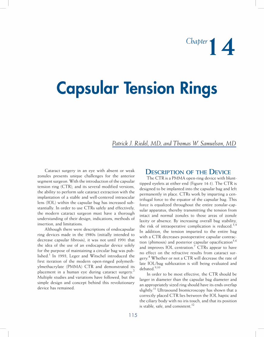
115
Cataract surgery in an eye with absent or weak zonules presents unique challenges for the anterior segment surgeon. With the introduction of the capsular tension ring (CTR), and its several modified versions, the ability to perform safe cataract extraction with the implantation of a stable and well-centered intraocular lens (IOL) within the capsular bag has increased sub-stantially. In order to use CTRs safely and effectively, the modern cataract surgeon must have a thorough understanding of their design, indications, methods of insertion, and limitations.
Although there were descriptions of endocapsular ring devices made in the 1980s (initially intended to decrease capsular fibrosis), it was not until 1991 that the idea of the use of an endocapsular device solely for the purpose of maintaining a circular bag was pub-lished.1 In 1993, Leger and Witschel introduced the first iteration of the modern open-ringed polymeth-ylmethacrylate (PMMA) CTR and demonstrated its placement in a human eye during cataract surgery.2
Multiple studies and variations have followed, but the simple design and concept behind this revolutionary device has remained.
Description of the DeviceThe CTR is a PMMA open-ring device with blunt-
tipped eyelets at either end (Figure 14-1). The CTR is designed to be implanted into the capsular bag and left permanently in place. CTRs work by imparting a cen-trifugal force to the equator of the capsular bag. This force is equalized throughout the entire zonular-cap-sular apparatus, thereby transmitting the tension from intact and normal zonules to those areas of zonule laxity or absence. By increasing overall bag stability, the risk of intraoperative complication is reduced.3,4 In addition, the tension imparted to the entire bag with a CTR decreases postoperative capsular contrac-tion (phimosis) and posterior capsular opacification5,6
and improves IOL centration.7 CTRs appear to have no effect on the refractive results from cataract sur-gery.8 Whether or not a CTR will decrease the rate of late IOL/bag subluxation is still being evaluated and debated.9,10
In order to be most effective, the CTR should be larger in diameter than the capsular bag diameter and an appropriately sized ring should have its ends overlap slightly.11 Ultrasound biomicroscopy has shown that a correctly placed CTR lies between the IOL haptic and the ciliary body with no iris touch, and that its position is stable, safe, and consistent.12
Capsular Tension Rings
Patrick J. Riedel, MD, and Thomas W. Samuelson, MD
Chapter14
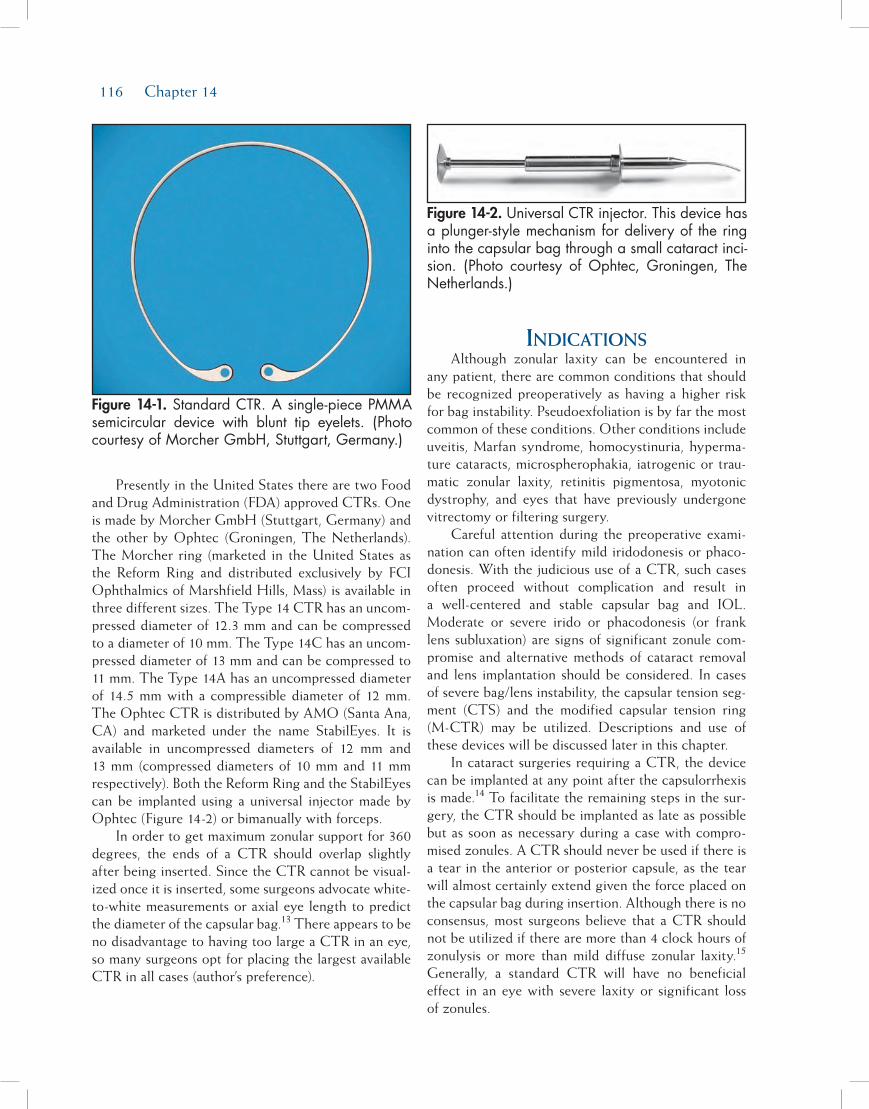
116 Chapter 14
Presently in the United States there are two Food and Drug Administration (FDA) approved CTRs. One is made by Morcher GmbH (Stuttgart, Germany) and the other by Ophtec (Groningen, The Netherlands). The Morcher ring (marketed in the United States as the Reform Ring and distributed exclusively by FCI Ophthalmics of Marshfield Hills, Mass) is available in three different sizes. The Type 14 CTR has an uncom-pressed diameter of 12.3 mm and can be compressed to a diameter of 10 mm. The Type 14C has an uncom-pressed diameter of 13 mm and can be compressed to 11 mm. The Type 14A has an uncompressed diameter of 14.5 mm with a compressible diameter of 12 mm. The Ophtec CTR is distributed by AMO (Santa Ana, CA) and marketed under the name StabilEyes. It is available in uncompressed diameters of 12 mm and 13 mm (compressed diameters of 10 mm and 11 mm respectively). Both the Reform Ring and the StabilEyes can be implanted using a universal injector made by Ophtec (Figure 14-2) or bimanually with forceps.
In order to get maximum zonular support for 360 degrees, the ends of a CTR should overlap slightly after being inserted. Since the CTR cannot be visual-ized once it is inserted, some surgeons advocate white-to-white measurements or axial eye length to predict the diameter of the capsular bag.13 There appears to be no disadvantage to having too large a CTR in an eye, so many surgeons opt for placing the largest available CTR in all cases (author’s preference).
inDicationsAlthough zonular laxity can be encountered in
any patient, there are common conditions that should be recognized preoperatively as having a higher risk for bag instability. Pseudoexfoliation is by far the most common of these conditions. Other conditions include uveitis, Marfan syndrome, homocystinuria, hyperma-ture cataracts, microspherophakia, iatrogenic or trau-matic zonular laxity, retinitis pigmentosa, myotonic dystrophy, and eyes that have previously undergone vitrectomy or filtering surgery.
Careful attention during the preoperative exami-nation can often identify mild iridodonesis or phaco-donesis. With the judicious use of a CTR, such cases often proceed without complication and result in a well-centered and stable capsular bag and IOL. Moderate or severe irido or phacodonesis (or frank lens subluxation) are signs of significant zonule com-promise and alternative methods of cataract removal and lens implantation should be considered. In cases of severe bag/lens instability, the capsular tension seg-ment (CTS) and the modified capsular tension ring (M-CTR) may be utilized. Descriptions and use of these devices will be discussed later in this chapter.
In cataract surgeries requiring a CTR, the device can be implanted at any point after the capsulorrhexis is made.14 To facilitate the remaining steps in the sur-gery, the CTR should be implanted as late as possible but as soon as necessary during a case with compro-mised zonules. A CTR should never be used if there is a tear in the anterior or posterior capsule, as the tear will almost certainly extend given the force placed on the capsular bag during insertion. Although there is no consensus, most surgeons believe that a CTR should not be utilized if there are more than 4 clock hours of zonulysis or more than mild diffuse zonular laxity.15 Generally, a standard CTR will have no beneficial effect in an eye with severe laxity or significant loss of zonules.
Figure 14-1. Standard CTR. A single-piece PMMA semicircular device with blunt tip eyelets. (Photo courtesy of Morcher GmbH, Stuttgart, Germany.)
Figure 14-2. Universal CTR injector. This device has a plunger-style mechanism for delivery of the ring into the capsular bag through a small cataract inci-sion. (Photo courtesy of Ophtec, Groningen, The Netherlands.)
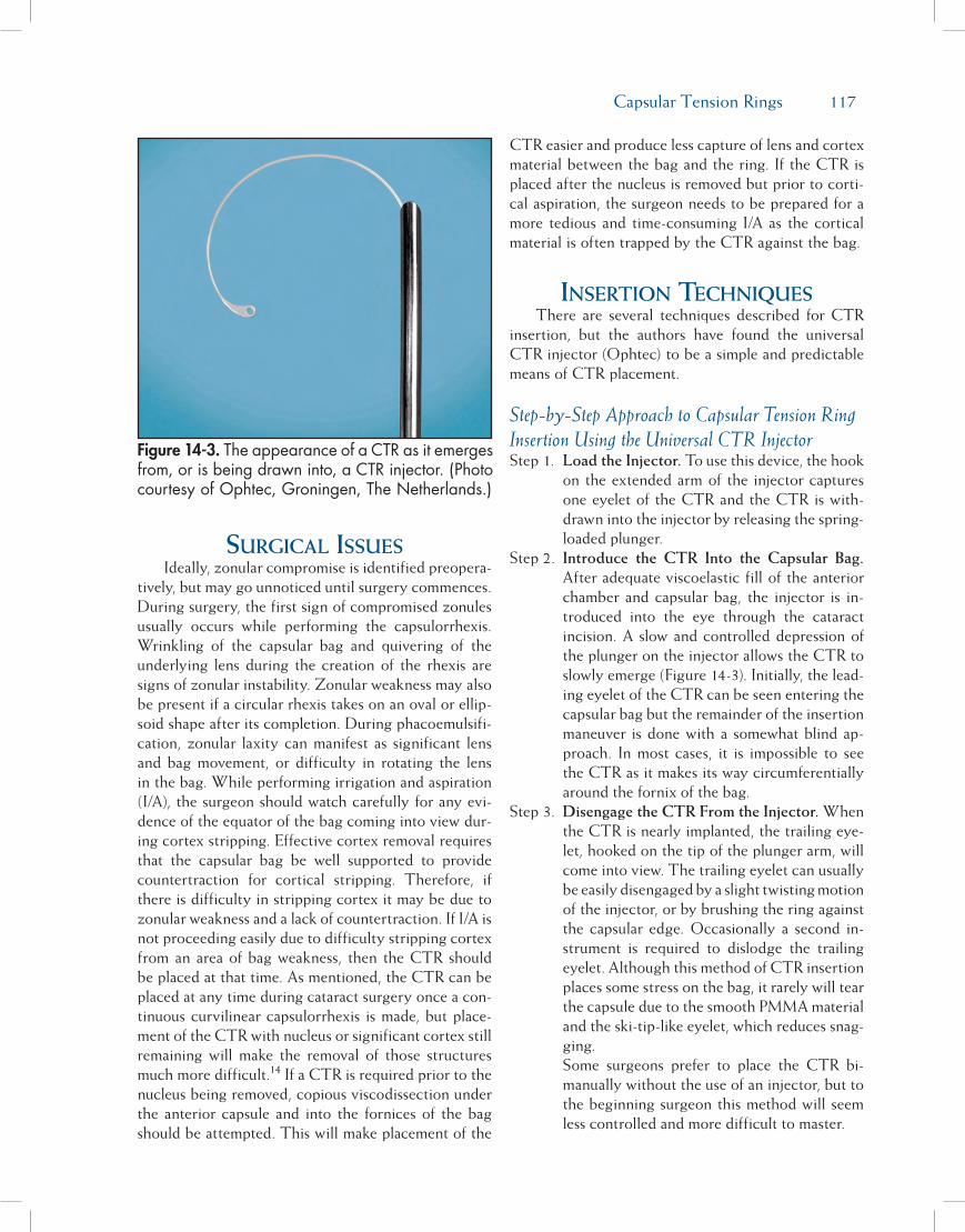
Capsular Tension Rings 117
surgical issuesIdeally, zonular compromise is identified preopera-
tively, but may go unnoticed until surgery commences. During surgery, the first sign of compromised zonules usually occurs while performing the capsulorrhexis. Wrinkling of the capsular bag and quivering of the underlying lens during the creation of the rhexis are signs of zonular instability. Zonular weakness may also be present if a circular rhexis takes on an oval or ellip-soid shape after its completion. During phacoemulsifi-cation, zonular laxity can manifest as significant lens and bag movement, or difficulty in rotating the lens in the bag. While performing irrigation and aspiration (I/A), the surgeon should watch carefully for any evi-dence of the equator of the bag coming into view dur-ing cortex stripping. Effective cortex removal requires that the capsular bag be well supported to provide countertraction for cortical stripping. Therefore, if there is difficulty in stripping cortex it may be due to zonular weakness and a lack of countertraction. If I/A is not proceeding easily due to difficulty stripping cortex from an area of bag weakness, then the CTR should be placed at that time. As mentioned, the CTR can be placed at any time during cataract surgery once a con-tinuous curvilinear capsulorrhexis is made, but place-ment of the CTR with nucleus or significant cortex still remaining will make the removal of those structures much more difficult.14 If a CTR is required prior to the nucleus being removed, copious viscodissection under the anterior capsule and into the fornices of the bag should be attempted. This will make placement of the
CTR easier and produce less capture of lens and cortex material between the bag and the ring. If the CTR is placed after the nucleus is removed but prior to corti-cal aspiration, the surgeon needs to be prepared for a more tedious and time-consuming I/A as the cortical material is often trapped by the CTR against the bag.
insertion techniquesThere are several techniques described for CTR
insertion, but the authors have found the universal CTR injector (Ophtec) to be a simple and predictable means of CTR placement.
Step-by-Step Approach to Capsular Tension Ring Insertion Using the Universal CTR InjectorStep 1. Load the Injector. To use this device, the hook
on the extended arm of the injector captures one eyelet of the CTR and the CTR is with-drawn into the injector by releasing the spring-loaded plunger.
Step 2. Introduce the CTR Into the Capsular Bag. After adequate viscoelastic fill of the anterior chamber and capsular bag, the injector is in-troduced into the eye through the cataract incision. A slow and controlled depression of the plunger on the injector allows the CTR to slowly emerge (Figure 14-3). Initially, the lead-ing eyelet of the CTR can be seen entering the capsular bag but the remainder of the insertion maneuver is done with a somewhat blind ap-proach. In most cases, it is impossible to see the CTR as it makes its way circumferentially around the fornix of the bag.
Step 3. Disengage the CTR From the Injector. When the CTR is nearly implanted, the trailing eye-let, hooked on the tip of the plunger arm, will come into view. The trailing eyelet can usually be easily disengaged by a slight twisting motion of the injector, or by brushing the ring against the capsular edge. Occasionally a second in-strument is required to dislodge the trailing eyelet. Although this method of CTR insertion places some stress on the bag, it rarely will tear the capsule due to the smooth PMMA material and the ski-tip-like eyelet, which reduces snag-ging.
Some surgeons prefer to place the CTR bi-manually without the use of an injector, but to the beginning surgeon this method will seem less controlled and more difficult to master.
Figure 14-3. The appearance of a CTR as it emerges from, or is being drawn into, a CTR injector. (Photo courtesy of Ophtec, Groningen, The Netherlands.)
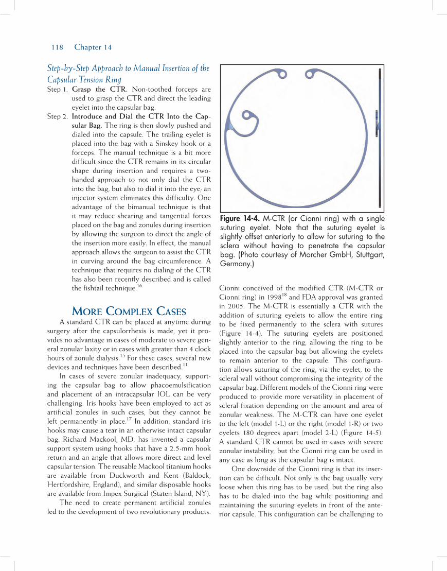
118 Chapter 14
Step-by-Step Approach to Manual Insertion of the Capsular Tension RingStep 1. Grasp the CTR. Non-toothed forceps are
used to grasp the CTR and direct the leading eyelet into the capsular bag.
Step 2. Introduce and Dial the CTR Into the Cap-sular Bag. The ring is then slowly pushed and dialed into the capsule. The trailing eyelet is placed into the bag with a Sinskey hook or a forceps. The manual technique is a bit more difficult since the CTR remains in its circular shape during insertion and requires a two-handed approach to not only dial the CTR into the bag, but also to dial it into the eye; an injector system eliminates this difficulty. One advantage of the bimanual technique is that it may reduce shearing and tangential forces placed on the bag and zonules during insertion by allowing the surgeon to direct the angle of the insertion more easily. In effect, the manual approach allows the surgeon to assist the CTR in curving around the bag circumference. A technique that requires no dialing of the CTR has also been recently described and is called the fishtail technique.16
More coMplex casesA standard CTR can be placed at anytime during
surgery after the capsulorrhexis is made, yet it pro-vides no advantage in cases of moderate to severe gen-eral zonular laxity or in cases with greater than 4 clock hours of zonule dialysis.15 For these cases, several new devices and techniques have been described.11
In cases of severe zonular inadequacy, support-ing the capsular bag to allow phacoemulsification and placement of an intracapsular IOL can be very challenging. Iris hooks have been employed to act as artificial zonules in such cases, but they cannot be left permanently in place.17 In addition, standard iris hooks may cause a tear in an otherwise intact capsular bag. Richard Mackool, MD, has invented a capsular support system using hooks that have a 2.5-mm hook return and an angle that allows more direct and level capsular tension. The reusable Mackool titanium hooks are available from Duckworth and Kent (Baldock, Hertfordshire, England), and similar disposable hooks are available from Impex Surgical (Staten Island, NY).
The need to create permanent artificial zonules led to the development of two revolutionary products.
Cionni conceived of the modified CTR (M-CTR or Cionni ring) in 199818 and FDA approval was granted in 2005. The M-CTR is essentially a CTR with the addition of suturing eyelets to allow the entire ring to be fixed permanently to the sclera with sutures (Figure 14-4). The suturing eyelets are positioned slightly anterior to the ring, allowing the ring to be placed into the capsular bag but allowing the eyelets to remain anterior to the capsule. This configura-tion allows suturing of the ring, via the eyelet, to the scleral wall without compromising the integrity of the capsular bag. Different models of the Cionni ring were produced to provide more versatility in placement of scleral fixation depending on the amount and area of zonular weakness. The M-CTR can have one eyelet to the left (model 1-L) or the right (model 1-R) or two eyelets 180 degrees apart (model 2-L) (Figure 14-5). A standard CTR cannot be used in cases with severe zonular instability, but the Cionni ring can be used in any case as long as the capsular bag is intact.
One downside of the Cionni ring is that its inser-tion can be difficult. Not only is the bag usually very loose when this ring has to be used, but the ring also has to be dialed into the bag while positioning and maintaining the suturing eyelets in front of the ante-rior capsule. This configuration can be challenging to
Figure 14-4. M-CTR (or Cionni ring) with a single suturing eyelet. Note that the suturing eyelet is slightly offset anteriorly to allow for suturing to the sclera without having to penetrate the capsular bag. (Photo courtesy of Morcher GmbH, Stuttgart, Germany.)
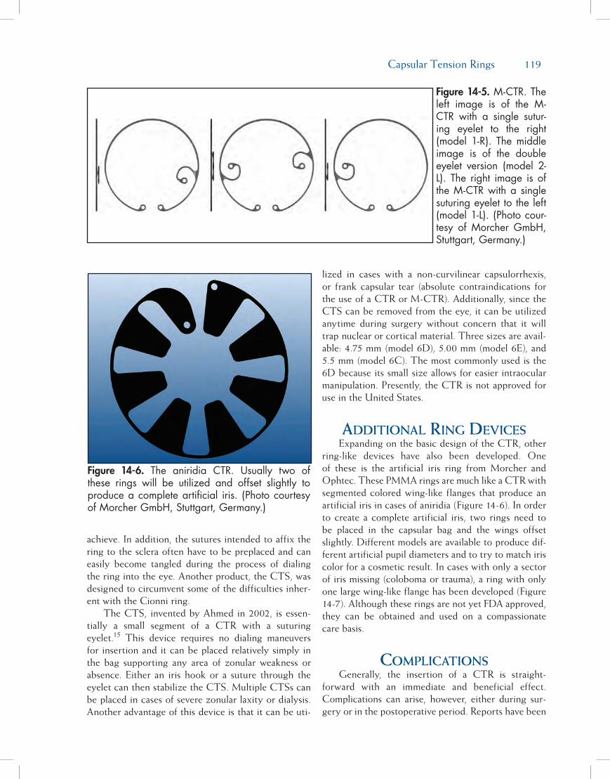
Capsular Tension Rings 119
achieve. In addition, the sutures intended to affix the ring to the sclera often have to be preplaced and can easily become tangled during the process of dialing the ring into the eye. Another product, the CTS, was designed to circumvent some of the difficulties inher-ent with the Cionni ring.
The CTS, invented by Ahmed in 2002, is essen-tially a small segment of a CTR with a suturing eyelet.15 This device requires no dialing maneuvers for insertion and it can be placed relatively simply in the bag supporting any area of zonular weakness or absence. Either an iris hook or a suture through the eyelet can then stabilize the CTS. Multiple CTSs can be placed in cases of severe zonular laxity or dialysis. Another advantage of this device is that it can be uti-
lized in cases with a non-curvilinear capsulorrhexis, or frank capsular tear (absolute contraindications for the use of a CTR or M-CTR). Additionally, since the CTS can be removed from the eye, it can be utilized anytime during surgery without concern that it will trap nuclear or cortical material. Three sizes are avail-able: 4.75 mm (model 6D), 5.00 mm (model 6E), and 5.5 mm (model 6C). The most commonly used is the 6D because its small size allows for easier intraocular manipulation. Presently, the CTR is not approved for use in the United States.
aDDitional ring DevicesExpanding on the basic design of the CTR, other
ring-like devices have also been developed. One of these is the artificial iris ring from Morcher and Ophtec. These PMMA rings are much like a CTR with segmented colored wing-like flanges that produce an artificial iris in cases of aniridia (Figure 14-6). In order to create a complete artificial iris, two rings need to be placed in the capsular bag and the wings offset slightly. Different models are available to produce dif-ferent artificial pupil diameters and to try to match iris color for a cosmetic result. In cases with only a sector of iris missing (coloboma or trauma), a ring with only one large wing-like flange has been developed (Figure 14-7). Although these rings are not yet FDA approved, they can be obtained and used on a compassionate care basis.
coMplicationsGenerally, the insertion of a CTR is straight-
forward with an immediate and beneficial effect. Complications can arise, however, either during sur-gery or in the postoperative period. Reports have been
Figure 14-5. M-CTR. The left image is of the M-CTR with a single sutur-ing eyelet to the right (model 1-R). The middle image is of the double eyelet version (model 2-L). The right image is of the M-CTR with a single suturing eyelet to the left (model 1-L). (Photo cour-tesy of Morcher GmbH, Stuttgart, Germany.)
Figure 14-6. The aniridia CTR. Usually two of these rings will be utilized and offset slightly to produce a complete artificial iris. (Photo courtesy of Morcher GmbH, Stuttgart, Germany.)
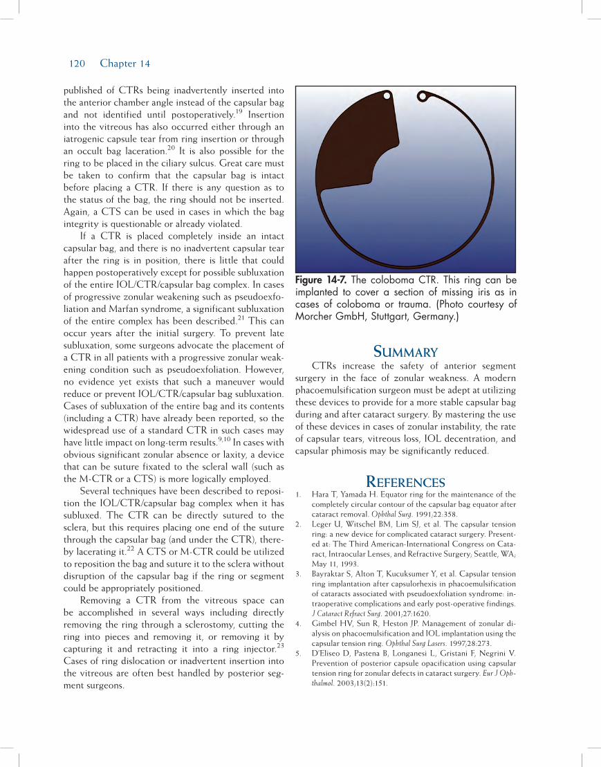
120 Chapter 14
published of CTRs being inadvertently inserted into the anterior chamber angle instead of the capsular bag and not identified until postoperatively.19 Insertion into the vitreous has also occurred either through an iatrogenic capsule tear from ring insertion or through an occult bag laceration.20 It is also possible for the ring to be placed in the ciliary sulcus. Great care must be taken to confirm that the capsular bag is intact before placing a CTR. If there is any question as to the status of the bag, the ring should not be inserted. Again, a CTS can be used in cases in which the bag integrity is questionable or already violated.
If a CTR is placed completely inside an intact capsular bag, and there is no inadvertent capsular tear after the ring is in position, there is little that could happen postoperatively except for possible subluxation of the entire IOL/CTR/capsular bag complex. In cases of progressive zonular weakening such as pseudoexfo-liation and Marfan syndrome, a significant subluxation of the entire complex has been described.21 This can occur years after the initial surgery. To prevent late subluxation, some surgeons advocate the placement of a CTR in all patients with a progressive zonular weak-ening condition such as pseudoexfoliation. However, no evidence yet exists that such a maneuver would reduce or prevent IOL/CTR/capsular bag subluxation. Cases of subluxation of the entire bag and its contents (including a CTR) have already been reported, so the widespread use of a standard CTR in such cases may have little impact on long-term results.9,10 In cases with obvious significant zonular absence or laxity, a device that can be suture fixated to the scleral wall (such as the M-CTR or a CTS) is more logically employed.
Several techniques have been described to reposi-tion the IOL/CTR/capsular bag complex when it has subluxed. The CTR can be directly sutured to the sclera, but this requires placing one end of the suture through the capsular bag (and under the CTR), there-by lacerating it.22 A CTS or M-CTR could be utilized to reposition the bag and suture it to the sclera without disruption of the capsular bag if the ring or segment could be appropriately positioned.
Removing a CTR from the vitreous space can be accomplished in several ways including directly removing the ring through a sclerostomy, cutting the ring into pieces and removing it, or removing it by capturing it and retracting it into a ring injector.23 Cases of ring dislocation or inadvertent insertion into the vitreous are often best handled by posterior seg-ment surgeons.
suMMaryCTRs increase the safety of anterior segment
surgery in the face of zonular weakness. A modern phacoemulsification surgeon must be adept at utilizing these devices to provide for a more stable capsular bag during and after cataract surgery. By mastering the use of these devices in cases of zonular instability, the rate of capsular tears, vitreous loss, IOL decentration, and capsular phimosis may be significantly reduced.
references1. Hara T, Yamada H. Equator ring for the maintenance of the
completely circular contour of the capsular bag equator after cataract removal. Ophthal Surg. 1991;22:358.
2. Leger U, Witschel BM, Lim SJ, et al. The capsular tension ring: a new device for complicated cataract surgery. Present-ed at: The Third American-International Congress on Cata-ract, Intraocular Lenses, and Refractive Surgery; Seattle, WA; May 11, 1993.
3. Bayraktar S, Alton T, Kucuksumer Y, et al. Capsular tension ring implantation after capsulorhexis in phacoemulsification of cataracts associated with pseudoexfoliation syndrome: in-traoperative complications and early post-operative findings. J Cataract Refract Surg. 2001;27:1620.
4. Gimbel HV, Sun R, Heston JP. Management of zonular di-alysis on phacoemulsification and IOL implantation using the capsular tension ring. Ophthal Surg Lasers. 1997;28:273.
5. D’Eliseo D, Pastena B, Longanesi L, Gristani F, Negrini V. Prevention of posterior capsule opacification using capsular tension ring for zonular defects in cataract surgery. Eur J Oph-thalmol. 2003;13(2):151.
Figure 14-7. The coloboma CTR. This ring can be implanted to cover a section of missing iris as in cases of coloboma or trauma. (Photo courtesy of Morcher GmbH, Stuttgart, Germany.)

Capsular Tension Rings 121
6. Kim JH, Kim H, Joo CK. The effect of capsular tension ringon posterior capsular opacity in cataract surgery. Korean J Ophthalmol. 2005;19(1):23.
7. Lee DH, Shin SC, Joo CK. Effect of the capsular tension ringon intraocular lens decentration and tilting after cataract sur-gery. J Cataract Refract Surg. 2002;28(5):843.
8. Boomer JA, Jackson DW. Effect of the Morcher capsulartension ring on refractive outcomes. J Cataract Refract Surg.2006;32(7):1180.
9. Scherer M, Bertelmann E, Rieck P. Late spontaneous in-the-bag intraocular lens and capsular tension ring disloca-tion in pseudoexfoliation syndrome. J Cataract Refract Surg.2006;32(4):672.
10. Oner FH, Kocak N, Saatci AO. Dislocation of the capsularbag with intraocular lens and capsular tension ring. J Cataract Refract Surg. 2006;32(10):1756.
11. Goldman JM, Karp CL. Adjunct devices for managing chal-lenging cases in cataract surgery: pupil expansion and stabili-zation of the capsular bag. Curr Opin Ophthalmol. 2007;18:44.
12. Boomer JA, Jackson DW. Anatomic evaluation of the Morchercapsular tension ring by ultrasound biomicroscopy. J Cataract Refract Surg. 2006;32(5):846.
13. Vass C, Menapace R, Schetterer K, et al. Prediction of pseu-dophakic capsular bag diameter based on biometric variables.J Cataract Refract Surg. 1999;25:1376.
14. Ahmed II, Cionni RJ, Kranemann C, Crandall AS. Optimal
timing of capsular tension ring implantation: Miyake-Apple video analysis. J Cataract Refract Surg. 2005;31(9):1809.
15. Hasanee K, Ahmed II. Capsular tension rings: update on endo-capsular support devices. Ophthalmol Clin N Am. 2006;19:508.
16. Anqunawela RI, Little B. Fishtail technique for capsular ten-sion ring insertion. J Cataract Refract Surg. 2007:33(5):767.
17. Lee V, Bloom P. Microhook capsular stabilization for phaco-emulsification in eyes with pseudoexfoliation-induced lensinstability. J Cataract Refract Surg. 1999;25:1567.
18. Cionni,RJ, Osher RH. Management of profound zonular di-alysis or weakness with a new endocapsular ring designed forscleral fixation. J Cataract Refract Surg. 1998;24:1299.
19. Little BC, Richardson T, Morris S. Removal of the capsulartension ring from the anterior chamber angle. J Cataract Re-fract Surg. 2004;30(9):1832.
20. Levy J, Klemperer I, Lifshitz T. Posteriorly dislocated capsu-lar tension ring. Ophthal Surg Lasers Imaging. 2005;36(5):416.
21. Jehan FS, Mamalis N, Crandall AS. Spontaneous late disloca-tion of the intraocular lens within the capsular bag in pseudo-exfoliation patients. Ophthalmology. 2001;108(10):1727.
22. Ahmed II, Chen SH, Kranemann C, Wong DT. Surgical re-positioning of dislocated capsular tension rings. Ophthalmol-ogy. 2005;112(10):1725.
23. Ma PE, Kaur H, Petrovic V, Hay D. Technique for removalof a capsular tension ring from the vitreous. Ophthalmology.2003;110(6):1142.

123
Preventing PostoPerative infection
Postoperative endophthalmitis is a rare but poten-tially devastating complication of cataract surgery. The incidence of postoperative endophthalmitis is small and most recent studies have found that in the United States, the rate is approximately 0.07%.1-3 With an ever-aging population, the number of patients requir-ing cataract surgery is growing each year. Therefore, potential cases of postoperative endophthalmitis will increase in the future. Given the potential for a poor visual outcome following endophthalmitis, it is critical-ly important that all possible methods for the preven-tion of endophthalmitis be employed. These methods of prophylaxis include preoperative, intraoperative, and postoperative techniques and medications that will help lower the overall incidence of endophthalmitis.
PreoperativeThe first step in the prevention of endophthalmitis
is the recognition and treatment of any preexisting conditions that may predispose the patient to the devel-opment of endophthalmitis. This should begin with the initial evaluation of the patient with a surgical cataract in the clinic. Careful history should be taken regarding
any preexisting diseases and/or history of previous ocu-lar infections. Conditions that may lead to increased bacteria periocularly should be recognized with careful evaluation of the patient at the slit lamp. Dacryocystitis or any abnormalities of the lacrimal drainage system, which may predispose to infections, should be care-fully documented. It is important that these aforemen-tioned conditions be treated prior to cataract surgery to decrease the incidence of bacteria periocularly. Any preexisting dacryocystitis should be completely treated well before cataract surgery. Similarly, aggressive treat-ment of blepharitis and meibomian gland dysfunction should be undertaken prior to contemplating cataract surgery with aggressive lid soaks and scrubs, periocular antibiotics, as well as a course of oral antibiotics such as doxycycline if necessary prior to surgery. The patient should be evaluated following treatment of these condi-tions to ensure that he or she is under control prior to undergoing surgery.
Use of preoperative antibiotics is also important to obtain a high level of antibiotics in the cornea and anterior chamber prior to the first incision for cata-ract surgery.4 There are several ways to provide this preoperative antibiotic coverage. Studies have shown that antibiotics begun four times per day 3 days prior to surgery or even 1 day prior to surgery5 provide
Chapter
Preventing Postoperative Infection and Inflammation
Nick Mamalis, MD
15

124 Chapter 15
a high level of antibiotics in the cornea and anterior chamber.6 The use of preoperative antibiotics in a loading fashion prior to surgery may also provide high levels of antibiotics. Patients may receive four sets of antibiotic drops during their preoperative preparation for surgery at the time that dilating drops are given to the patient.
Topical fourth-generation fluoroquinolones have low ocular toxicity, superior penetration through the cornea, and higher minimum inhibitory concentration (MIC) levels in aqueous compared with third-gen-eration fluoroquinolones.7,8 In addition, the broad-spectrum coverage provided by these agents against both gram-positive and gram-negative organisms make them theoretically ideal for prevention of postopera-tive endophthalmitis.9,10 Fourth-generation fluoroqui-nolones such as moxifloxacin (Vigamox, Alcon, Fort Worth, TX) and gatifloxacin (Zymar, Allergan, Irvine, CA) have been shown to provide excellent prophylaxis for most bacteria that are responsible for postopera-tive endophthalmitis and can rapidly attain high levels within the cornea and the anterior chamber prior to surgery.
Preoperative preparation of the patients for sur-gery is also very important as reports have shown that normal ocular flora from the eyelids or conjunctiva are the most common bacteria causing endophthal-mitis.11,12 Skin preparation should be undertaken with 10% Betadine on the lid skin and lashes surrounding the eye. Vigorous scrubbing of the lashes should not be undertaken immediately before cataract surgery as this may actually liberate bacteria from the eyelashes. One of the most important factors in the preopera-tive sterilization of the surface of the eye is the use of 5% Betadine on the cornea and conjunctiva during preparation of the eye for surgery. This preoperative povidone-iodine antisepsis (when combined with pre-operative topical antibiotics therapy) has been shown to markedly decrease the bacteria that are present on the surface of the eye prior to cataract surgery.13,14
Great care should be taken during the draping of the patient prior to surgery to ensure that there is a barrier between the lid margin and lashes and the surgical field. There are many plastic drapes that are available that can perform this important func-tion. With the use of topical anesthesia, the patient is instructed to widely open his or her eyes and the sticky plastic drape is then placed over the eyelids and lashes. A sharp scissors can then be used to make an opening through the center of the drape overlying the cornea. Either an open- or closed-loop speculum may
then be used to “tuck” the plastic drape around the lid margin and lashes. This way, there will be no direct contact of potentially contaminated eyelid margin or lashes with the surgical field.
IntraoperativeIt is critical to maintain antiseptic techniques
throughout the entire procedure. Instruments that are used within the eye should be carefully sterilized and care should be taken not to break the sterility of the surgical field or the instrument tray at any time during the surgery.
The construction of the clear corneal wound used for the majority of cataract surgeries is critical. Several relatively recent studies have raised a concern that postoperative endophthalmitis following cataract sur-gery is more likely with clear corneal incisions.15-17 This concern is also backed by evidence of an increased rate of post-cataract endophthalmitis since 1994, which coincides with the timeline for widespread use of unsutured clear corneal cataract incisions.3 Proper construction of the clear corneal wound is important to ensure a water-tight closure at the conclusion of the case. Studies by Ernest and co-authors18 have shown that the clear corneal cataract wounds that are square or nearly square in architecture are significantly more resistant to external deformation than those that are more rectangular. In addition, Masket has shown that the design and length of the clear corneal incision is critical to ensure that the incision seals at the conclu-sion of the case.19 Meticulous construction of a clear corneal incision to ensure adequate sealing of the incision at the conclusion of the case should have an acceptably low risk of postoperative endophthalmi-tis.20 Newer methods of evaluating the clear corneal incision architecture have been developed using opti-cal coherence tomography. This imaging technol-ogy allows evaluation of the architectural features of the clear corneal wound in patients postoperatively. Endothelial gapping and loss of coaptation postopera-tively has been shown in some patients. This can be potentially important at times immediately following cataract surgery when the intraocular pressure (IOP) is low, which would significantly increase the risk for endophthalmitis.21
The role of antibiotics in the irrigating solution to try and prevent endophthalmitis during the procedure is quite controversial. Surgeons have advocated the use of antibiotics in the irrigating solution for prevention of endophthalmitis in the past.22 Gentamicin sulfate as

Preventing Postoperative Infection and Inflammation 125
well as vancomycin in the irrigating solution has been advocated. However, antibiotics within the irrigating solution provide a relatively low dose of antibiotics for a short period of time, which would not render a bacteriostatic antibiotic useful in the killing of bacteria during cataract surgery. There is also a concern about the possibility of toxicity from intraocular gentamicin use.23 In addition, the misdosing of the antibiotic with-in the irrigating solution has the potential for causing postoperative inflammation or toxic anterior segment syndrome (TASS). Therefore, antibiotics within the irrigating solution during cataract surgery are not recommended.
Another way of attaining a high dose of antibiotics at the immediate conclusion of cataract surgery is the use of intracameral antibiotics. Intracameral cefurox-ime has been evaluated for endophthalmitis prophylax-is and has gained widespread acceptance in countries such as Sweden. Montan and coauthors have shown that a 1.0 mL dose of intracameral cefuroxime appar-ently has no signs of toxicity on the corneal endothe-lium or on the anterior segment.24 The decreased rates of postoperative endophthalmitis in Sweden since the adaptation of cefuroxime helped stimulate the European Society of Cataract and Refractive Surgery (ESCRS) to perform a prospective, investiga-tor-masked, placebo-controlled multicenter clinical trial to evaluate the use of cefuroxime intracamerally in the prevention of endophthalmitis. The ESCRS study was a large multicenter study that eventually included greater than 16,000 patients. They found that risk for presumed infectious endophthalmitis postoperatively was increased nearly five-fold in patients who did not receive intracameral cefuroxime (0.30%) com-pared to those receiving the intracameral antibiotic (0.06%).25,26 However, there have been several ques-tions raised about the limitations of the ESCRS study following publication. First of all, levofloxacin was used for the topical antibiotic prophylaxis. Since that study began, the fourth-generation fluoroquinolones moxi-floxacin and gatifloxacin have gained widespread use in the United States and there is evidence to support the fact that these fourth-generation fluoroquinolones are a better choice for topical antibiotic prophylaxis to prevent endophthalmitis. Other methods of providing intracameral antibiotic prophylaxis are being evaluated at the moment. Fourth-generation fluoroquinolones such as moxifloxacin, which have potent and rapid bacteriocidal activity against common gram-positive pathogens, have been evaluated. There are theoretic advantages to the use of these fourth-generation fluo-
roquinolones as an agent for intracameral prophylaxis of endophthalmitis.27
An additional concern at this time is that no com-mercially available, Food and Drug Administration approved antibiotics are available to the ophthalmic surgeon in a unit dose delivery device for the use of these antibiotics intracamerally. These antibiotics have to be custom mixed for injection into the anterior chamber at the conclusion of the case. This raises the potential for problems regarding the administering of “homemade” intracameral antibiotics. Possible dilution errors, bacterial contamination, or even the creation of TASS is a concern. A recent survey of members of the American Society of Cataract and Refractive Surgery (ASCRS) found that this was a significant concern to 45% of surgeons currently not using intracameral anti-biotics. At present, more than 80% of ASCRS mem-bers expressed a need for a commercially approved preparation at a reasonable cost that would lead to routine injection of intracameral antibiotics.28
PostoperativeUse of postoperative antibiotics for the prevention
of endophthalmitis following cataract surgery has now become routine and some may argue that this is the standard of care. However, there is very limited and often indirect evidence regarding the efficacy of the use of postoperative antibiotics in the prevention of endophthalmitis. The huge numbers necessary to per-form a study as well as the ethical issues involved with the use of a placebo make randomized, prospective, controlled studies very difficult to perform to confirm the efficacy of postoperative antibiotics in the preven-tion of endophthalmitis. When postoperative antibiot-ics are used, it is very important that they be used in a proper manner. There has been a marked increase in resistance to second generation fluoroquinolones noted over the past decade.29-31 The rapid increase in resistance to so-called second-generation fluoroqui-nolones has rendered these drugs much less useful in the prophylaxis of postoperative endophthalmitis. The most common bacteria implicated in endophthalmitis are coagulase-negative staph, Staph aureus, and strep species. The availability of fourth-generation fluoro-quinolones gatifloxacin and moxifloxacin has lead to their widespread use for postoperative prophylaxis of endophthalmitis. The incidence of resistance to these new fluoroquinolones is much decreased compared to older generations. However, resistance even to fourth-generation fluoroquinolones is now being reported.32

126 Chapter 15
At the conclusion of the surgical procedure, two drops of fourth-generation fluoroquinolone should be placed onto the cornea while the patient is still in the operating room. The patient should then be instructed to use this antibiotic every 2 hours for the first day following surgery. The fourth-generation fluoroquino-lone antibiotic should then be used four times per day for 7 days following surgery and should be abruptly discontinued in routine cases. There is no place for the tapering of antibiotics in the postoperative period as this may increase the risk of formation of resistance to these antibiotics.
The prevention of postoperative endophthalmitis following cataract surgery is a multi-faceted procedure. This begins with a thorough preoperative evaluation of the patient including treatment of any preexisting dac-ryocystitis and blepharitis. Preoperative preparation of the patient including the use of antibiotics and povi-done-iodine is essential. Careful attention to draping and preparing of the patient’s eye with adherence to aseptic techniques is important. The design and con-struction of a clear corneal wound is critical to allow sealing of the wound at the conclusion of the case to decrease the potential risk of ingress of bacteria. Lastly, the use of antibiotics intracamerally at the conclusion of the surgery as well as postoperatively should help to decrease the risk for postoperative endophthalmitis.
Preventing PostoPerative inflammation
Control of postoperative inflammation following cataract surgery is important to prevent sequelae of chronic inflammation such as corneal decompensation, glaucoma, synechiae formation, and cystoid macular edema (CME). Control of postoperative inflamma-tion becomes even more important in patients with conditions that predispose them to breakdown of the blood aqueous barrier such as diabetes, and a history of preexisting iritis or uveitis. As with the prevention of infection, the prevention of postoperative inflam-mation begins in the preoperative period and extends through the surgery to the postoperative period.
PreoperativePatients with a history of uveitis, iritis, or any
inflammatory condition should be carefully evaluated in the clinic prior to consideration of cataract surgery. It is essential that there is no active uveitis present at the time of cataract surgery. The patient’s eye should
be quiet preoperatively for a minimum of 6 weeks prior to contemplating cataract surgery. In patients with a history of uveitis, it is recommended that anti-inflammatory drops be started at least 1 week prior to surgery. Prednisolone acetate (Pred Forte [Allergan, Irvine, CA]) as well as a nonsteroidal anti-inflamma-tory drug (NSAID) should be used four times per day for the week prior to surgery. In patients with a history of severe uveitis, oral prednisone in a moderate dose of 40 to 50 mg per day may also be started during this period of time.
In a routine cataract patient without a history of preexisting uveitis, it is unclear how soon prior to surgery that NSAID use should be started. There are advantages in beginning NSAID therapy prior to surgery so that there is adequate blockage of pros-taglandins release at the time of surgery. In addition, use of NSAIDs preoperatively will help to prevent progressive pupil miosis during the surgical procedure. Preoperative NSAID regimens for the treatment of anterior segment inflammation vary from beginning treatment 1 to 3 days prior to surgery to starting with a dose immediately before surgery. This is quite similar to the use of preoperative antibiotics for the prevention of endophthalmitis. It is reasonable to begin NSAID treatment when the patient is in the preoperative hold-ing area with three drops of NSAID given at the same time as the antibiotic and dilating drops. Some would argue that preoperative treatment with NSAIDs fol-lowed by combination therapy with NSAIDs and cor-ticosteroids postoperatively has become the standard of care in cataract surgery.33,34
PostoperativeThe most common postoperative regimen for the
treatment of inflammation in a routine cataract patient is the use of 1% prednisolone acetate four times per day for 2 weeks with tapering depending on the condi-tion of the patient and any preexisting conditions that would cause a breakdown of the blood-aqueous barrier postoperatively. This can be supplemented by NSAID treatments, which are once again used four times per day with a similar tapering dose. Postoperative use of anti-inflammatory medications such as corticosteroids or NSAIDs may help reduce inflammation and pre-vent possible postoperative complications.35 The use of NSAIDs in addition to corticosteroids or used by themselves prophylactically may help prevent postop-erative inflammation and sequelae such as CME.36
There are many different NSAIDs available for the prevention of postoperative inflammation as well
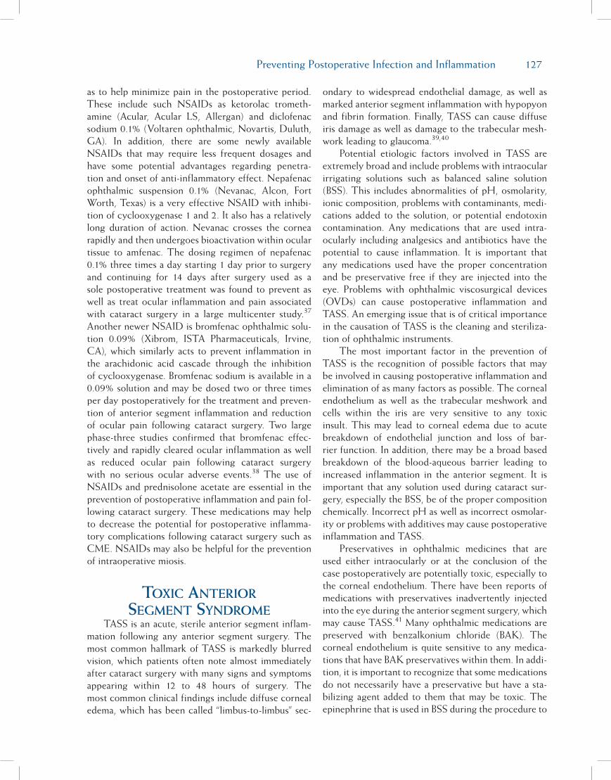
Preventing Postoperative Infection and Inflammation 127
as to help minimize pain in the postoperative period. These include such NSAIDs as ketorolac trometh-amine (Acular, Acular LS, Allergan) and diclofenac sodium 0.1% (Voltaren ophthalmic, Novartis, Duluth, GA). In addition, there are some newly available NSAIDs that may require less frequent dosages and have some potential advantages regarding penetra-tion and onset of anti-inflammatory effect. Nepafenac ophthalmic suspension 0.1% (Nevanac, Alcon, Fort Worth, Texas) is a very effective NSAID with inhibi-tion of cyclooxygenase 1 and 2. It also has a relatively long duration of action. Nevanac crosses the cornea rapidly and then undergoes bioactivation within ocular tissue to amfenac. The dosing regimen of nepafenac 0.1% three times a day starting 1 day prior to surgery and continuing for 14 days after surgery used as a sole postoperative treatment was found to prevent as well as treat ocular inflammation and pain associated with cataract surgery in a large multicenter study.37
Another newer NSAID is bromfenac ophthalmic solu-tion 0.09% (Xibrom, ISTA Pharmaceuticals, Irvine, CA), which similarly acts to prevent inflammation in the arachidonic acid cascade through the inhibition of cyclooxygenase. Bromfenac sodium is available in a 0.09% solution and may be dosed two or three times per day postoperatively for the treatment and preven-tion of anterior segment inflammation and reduction of ocular pain following cataract surgery. Two large phase-three studies confirmed that bromfenac effec-tively and rapidly cleared ocular inflammation as well as reduced ocular pain following cataract surgery with no serious ocular adverse events.38 The use of NSAIDs and prednisolone acetate are essential in the prevention of postoperative inflammation and pain fol-lowing cataract surgery. These medications may help to decrease the potential for postoperative inflamma-tory complications following cataract surgery such as CME. NSAIDs may also be helpful for the prevention of intraoperative miosis.
toxic anterior segment syndrome
TASS is an acute, sterile anterior segment inflam-mation following any anterior segment surgery. The most common hallmark of TASS is markedly blurred vision, which patients often note almost immediately after cataract surgery with many signs and symptoms appearing within 12 to 48 hours of surgery. The most common clinical findings include diffuse corneal edema, which has been called “limbus-to-limbus” sec-
ondary to widespread endothelial damage, as well as marked anterior segment inflammation with hypopyon and fibrin formation. Finally, TASS can cause diffuse iris damage as well as damage to the trabecular mesh-work leading to glaucoma.39,40
Potential etiologic factors involved in TASS are extremely broad and include problems with intraocular irrigating solutions such as balanced saline solution (BSS). This includes abnormalities of pH, osmolarity, ionic composition, problems with contaminants, medi-cations added to the solution, or potential endotoxin contamination. Any medications that are used intra-ocularly including analgesics and antibiotics have the potential to cause inflammation. It is important that any medications used have the proper concentration and be preservative free if they are injected into the eye. Problems with ophthalmic viscosurgical devices (OVDs) can cause postoperative inflammation and TASS. An emerging issue that is of critical importance in the causation of TASS is the cleaning and steriliza-tion of ophthalmic instruments.
The most important factor in the prevention of TASS is the recognition of possible factors that may be involved in causing postoperative inflammation and elimination of as many factors as possible. The corneal endothelium as well as the trabecular meshwork and cells within the iris are very sensitive to any toxic insult. This may lead to corneal edema due to acute breakdown of endothelial junction and loss of bar-rier function. In addition, there may be a broad based breakdown of the blood-aqueous barrier leading to increased inflammation in the anterior segment. It is important that any solution used during cataract sur-gery, especially the BSS, be of the proper composition chemically. Incorrect pH as well as incorrect osmolar-ity or problems with additives may cause postoperative inflammation and TASS.
Preservatives in ophthalmic medicines that are used either intraocularly or at the conclusion of the case postoperatively are potentially toxic, especially to the corneal endothelium. There have been reports of medications with preservatives inadvertently injected into the eye during the anterior segment surgery, which may cause TASS.41 Many ophthalmic medications are preserved with benzalkonium chloride (BAK). The corneal endothelium is quite sensitive to any medica-tions that have BAK preservatives within them. In addi-tion, it is important to recognize that some medications do not necessarily have a preservative but have a sta-bilizing agent added to them that may be toxic. The epinephrine that is used in BSS during the procedure to
128 Chapter 15
help prevent pupil miosis needs to be preservative free. This includes bisulphites and metabisulphites, which are technically stabilizers rather than preservatives, but may still be toxic to the corneal endothelium.
Intraocular anesthetics that are used during cata-ract surgery once again need to be preservative free. In addition, any intraocular anesthetic should be of the proper concentration. Preservative free lidocaine at a 1% dose appears to be safe for cataract surgery. However, dosages higher than 2% have been found to cause significant corneal thickening and opacification postoperatively.42-44 Therefore, intraocular anesthetics should not only be preservative free but of the proper concentration.
The use of intraocular antibiotics has been dis-cussed previously. The use of gentamicin and van-comycin in irrigating solutions has been discouraged due to potential problems with toxicity, especially involving gentamicin. While intracameral antibiotics such as cefuroxime have been shown to be safe when properly mixed, concerns have been raised with poten-tial problems involving “kitchen pharmacies.” Incorrect dosage, problems with sterility, and other issues with the customer mixing of intracameral antibiotics may potentially lead to issues with TASS.
OVDs are a potential source of TASS. It is essential that the OVDs be completely removed at the conclu-sion of the surgical procedure and that large amounts of OVDs are not left within the capsular bag or the posterior chamber. This could lead to increased post-operative inflammation and difficult to control IOP. In addition, OVD residues on reusable cannulas and irrigation/aspiration tips that are not properly flushed following cataract surgery may be associated with TASS. This retained OVD may become broken down or altered during sterilization, which can cause toxic inflammation when this is subsequently flushed into the eye.45
Another potential source of TASS that may occur either acutely or on a delayed onset basis is the ingress of topical ophthalmic ointment, used postoperatively, into the anterior segment of the eye. Many ophthal-mic ointments are petroleum based and deposition of hydrocarbon material within the vehicle of these postoperative ointments may cause toxicity within the eye.46 This ingress of ointment is only possible through a clear corneal wound that is not water tight or incom-petent at the conclusion of the surgery and once again brings forth the importance of a well-constructed clear corneal wound.
The cleaning and sterilization of ophthalmic instruments has become a very important factor when analyzing outbreaks of TASS. Many centers are using enzymes and detergents in the cleaning of reusable ocular instruments between cases. Any residue of detergent or enzyme on the instruments is potentially inflamagenic. Enzymes or active ingredients in these detergents are often not deactivated in standard auto-claves and may cause significant inflammation when flushed into the eye when the instruments are used again.47 Detergent residues left on ophthalmic instru-ments can cause toxicity to the corneal endothelium. Breebaart and coauthors described severe toxic endo-thelial cell destruction following surgery with deter-gent residues found on reusable cannulas.48
In addition to possible residues of detergent or enzymes, outbreaks of TASS have been found to be related to endotoxin contamination of the instruments that occurs during sterilization. Ultrasounds or water baths that are used for the treatment of instruments following surgery may grow gram-negative bacteria. Although the bacteria are destroyed during heat ster-ilization in autoclaving, heat stable lipopolysaccharide endotoxins from the gram-negative bacteria cell wall remain active and may be attached to the instruments following stabilization. Injection of the endotoxin into the eye during the surgery may cause significant ante-rior segment inflammation.49
The potential etiologic factors involved in an out-break of TASS are extremely broad. Analysis of TASS outbreaks often reveals multiple potential sources rather than a single point source associated with the outbreak.50 The increased incidence of TASS over the past 2 years has lead to the formation of an ASCRS-sponsored TASS task force to evaluate outbreaks of TASS. Educational materials from the task force are available including a video symposium involving mem-bers of the task force with input from nursing organiza-tions involved in ophthalmology (www.tassfacts.com). In addition, reports from the task force are available on the ASCRS Web site (www.ascrs.org) as well as on the American Academy of Ophthalmology Web site (www.aao.org). A complete guideline for the cleaning and sterilization of ophthalmic instruments is also avail-able on the ASCRS Web site and has been published recently.51 The prevention of TASS is a team effort involving not only the surgeon but the entire operating room staff including nurses and those involved in the cleaning and sterilization of instruments as well as the ordering of ophthalmic medications.

Preventing Postoperative Infection and Inflammation 129
references1. Moshirfar M, Feiz V, Vitale AT, et al. Endophthalmitis after
uncomplicated cataract surgery with the use of fourth-gen-eration fluoroquinolones: a retrospective observational case series. Ophthalmology. 2007;114:686-691.
2. Taban M, Behrens A, Newcomb RL, et al. Acute endophthal-mitis following cataract surgery: a systematic review of the literature. Arch Ophthalmol. 2005;123:613-620.
3. West ES, BehrensA, McDonnell PJ, et al. The incidence of endophthalmitis after cataract surgery among the U.S. Medi-care population increased between 1994 and 2001. Ophthal-mology. 2005;112:1388-1394.
4. Liesegang TJ. Use of antimicrobials to prevent postopera-tive infection in patients with cataracts. Curr Opin Ophthalmol. 2001;12:68-74.
5. Ta CN, Egbert PR, Singh K, et al. Prospective randomized comparison of 3-day versus 1-hour preoperative ofloxacin pro-phylaxis for cataract surgery. Ophthalmology. 2002;109:2036-2041.
6. Ta CN, Sinnar S, He L, et al. Prospective randomized com-parison of 1-day versus 3-day application of topical levo-floxacin in eliminating conjunctival flora. Eur J Ophthalmol. 2007;17:689-695.
7. Solomon R, Donnenfeld Ed, Perry HD, et al. Penetration of topically applied gatifloxacin 0.3%, moxifloxacin 0.5% and ciprofloxacin 0.3% into the aqueous humor. Ophthalmology. 2005;112:466-469.
8. Kim DH, Stark WJ, O’Brien TP, Dick JD. Aqueous penetra-tion and biological activity of moxifloxacin 0.5% ophthalmic solution and gatifloxacin 0.3% solution in cataract surgery patients. Ophthalmology. 2005;112:1992-1996.
9. Stroman DW, Dajcs JJ, Cupp GA, Schlech BA. In vitro and in vivo potency of moxifloxacin and moxifloxacin ophthalmic solution 0.5%, a new topical fluoroquinolone. Surv Ophthal-mol. 2005;50(suppl):S16-S31.
10. Kowalski RP, Dhaliwal DK, Karenchak LM, et al. Gatifloxa-cin and moxifloxacin: an in vitro susceptibility comparison to levofloxacin, ciprofloxacin, and ofloxacin using bacterial keratitis isolates. Am J Ophthalmol. 2003;136:500-505.
11. Bannerman TL, Rhoden DL, McAllister SK, et al. The source of coagulase-negative staphylococci in the Endophthalmitis Vitrectomy Study. A comparison of eyelid and intraocular isolates using pulsed-field gel electrophoresis. Arch Ophthal-mol. 1997;115:357-361.
12. Speaker MG, Milch FA, Shah MK, et al. Role of external bac-terial flora in the pathogenesis of acute postoperative endo-phthalmitis. Ophthalmology. 1991;98:639-49.
13. Speaker MG, Menikoff JA. Prophylaxis of endophthalmitis with topical povidone-iodine. Ophthalmology. 1991;98:1769-1775.
14. Ciulla TA, Star MB, Masket S. Bacterial endophthalmitis prophylaxis for cataract surgery: an evidence-based update. Ophthalmology. 2002;109:13-24.
15. Cooper BA, Holekamp NM, Bohigian G, Thompson PA. Case-control study of endophthalmitis after cataract surgery comparing scleral tunnel and clear corneal wounds. Am J Ophthalmol. 2003;136:300-305.
16. Colleaux KM, Hamilton WK. Effective prophylactic antibi-otics and incision type on the incidence of endophthalmitis after cataract surgery. Can J Ophthalmol. 2000;35:373-378.
17. Nagaki Y, Hayasaka S, Kadoi C, et al. Bacterial endophthal-mitis after small incision cataract surgery: effective incision
placement and intraocular lens type. J Cataract Refract Surg. 2003;29:20-26.
18. Ernest P, Kiessling LA, Lavery KT. Relative strength of cataract incisions in cadaver eyes. J Cataract Refract Surg. 1991;17:668-671.
19. Masket S. Is there a relationship between clear corneal cata-ract incisions and endophthalmitis? J Cataract Refract Surg. (Editorial) 2005;31:643-645.
20. Nichamin LD, Chang DF, Johnson SH, et al. ASCRS White Paper: what is the association between clear corneal cataract incisions and postoperative endophthalmitis? J Cataract Re-fract Surg. 2006;32:1556-1559.
21. Calladine D, Packard R. Clear corneal incision architecture in the immediate postoperative period evaluated using optical coherence tomography. J Cataract Refract Surg. 2007;33:1429-1435.
22. Gills JP. Filters and antibiotics in irrigating solution for cata-ract surgery (letter). J Cataract Refract Surg. 1991;17:385.
23. Campochiaro PA, Conway BP. Immunoglycoside toxicity–a survey of retinal specialists: implications for ocular use. Arch Ophthalmol. 1991;109:946-950.
24. Montan PG, Wejde G, Setterquist H, et al. Prophylactic in-tracameral cefuroxime: evaluation of safety and kinetics in cataract surgery. J Cataract Refract Surg. 2002;28:977-981.
25. Barry P, Cod V, Gettinby G, et al. ESCRS study of prophy-laxis of postoperative endophthalmitis after cataract surgery: preliminary report of principal results from a European multi-center study;ESCRS endophthalmitis study group. J Cataract Refract Surg. 2006;32:407-410.
26. ESCRS endophthalmitis study group. Prophylaxis of postop-erative endophthalmitis following cataract surgery: results of ESCRS multi-center study on identification of risk factors. J Cataract Refract Surg. 2007;33:978-988.
27. O’Brien TP, Arshinoff SA, Mah FS. Perspectives on antibiot-ics for postoperative endophthalmitis prophylaxis: potential role of moxifloxacin. J Cataract Refract Surg. 2007;33:1790-1800.
28. Chang DF, Braga-Mele R, Mamalis N, et al. Prophylaxis of postoperative endophthalmitis after cataract surgery: results of the 2007 ASCRS member survey. J Cataract Refract Surg. 2007;33:1801-1805.
29. Goldstein MH, Kowalski RP, Gordon YJ. Emerging fluoro-quinolone resistance in bacterial keratitis: a five-year review. Ophthalmology. 1999;106:1313-1318.
30. Alexandrakis G, Alfonso EC, Miller D. Shifting trends in bacterial keratitis in south Florida and emerging resistance to fluoroquinolones. Ophthalmology. 2000;107:1497-1502.
31. Kowalski RP, Pandya AN, Karenchak LM, et al. An in vitro resistance study of levofloxacin, ciprofloxacin, and ofloxacin using keratitis isolates of Staphylococcus aureus and Pseudo-monas aeruginosa. Ophthalmology. 2001;108:1826-1829.
32. Deramo VA, Lai JC, Fastenberg DM, et al. Acute endo-phthalmitis in eyes treated prophylactically with gatifloxacin and moxifloxacin. Am J Ophthalmol. 2006;142:721-725.
33. Solomon KD, Vroman DT, Barker D, Gehlken J. Compari-son of ketorolac tromethamine 0.5% and rimexolone 1% to control inflammation after cataract extraction: perspective randomized double-masked study. J Cataract Refract Surg. 2001;27:1232-1237.
34. O’Brien TP. Emerging guidelines for the use of NSAID ther-apy to optimize cataract surgery patient care. Curr Med Res Opin. 2005;21:1131-1137.

130 Chapter 15
35. Rowen S. Preoperative and postoperative medications used for cataract surgery. Curr Opin Ophthalmol. 1999;10:29-35.
36. Flach AJ. Topical non-steroidal anti-inflammatory drugs in ophthalmology. Int Ophthalmol Clin. 2002;42:1-11.
37. Lane SS, Modi SS, Lehmann RP, Holland EJ. Nepfenac oph-thalmic suspension 0.1% for the prevention and treatment of ocular inflammation associated with cataract surgery. J Cata-ract Refract Surg. 2007;33:53-58.
38. Donnenfeld ED, Holland EJ, Stewart RH, et al. Bromfenac ophthalmic solution 0.09% (Xibrom) for postoperative ocular pain and inflammation. Ophthalmol. 2007;114:1654-1662.
39. Mamalis N, Edelhauser HE, Dawson DG, et al. Toxic anterior segment syndrome–Review/Update. J Cataract Refract Surg. 2006;32:324-333.
40. Mamalis N. Toxic anterior segment syndrome (Editorial). J Cataract Refract Surg. 2006;32:181-182.
41. Liu H, Routley I, Teichmann KD. Toxic endothelial cell de-struction from intraocular benzalkonium chloride. J Cataract Refract Surg. 2001;27:1746-1750.
42. Kadonosono K, Ito N, Yazama F, et al. Effect of intracameral anesthesia on the corneal endothelium. J Cataract Refract Surg. 1998;24:1377-1381.
43. Guzy M, Satici A, Dogan Z, Karadede S. The effect of bupi-vacaine and lidocaine on the corneal endothelium when ap-plied into the anterior chamber at the concentration supplied commercially. Ophthalmologica. 2002;216:113-117.
44. Kim T, Holley GP, Lee JH, et al. The effects of intraocu-lar lidocaine on the corneal endothelium. Ophthalmology. 1998;105:120-125.
45. Kim JH. Intraocular inflammation of denatured viscoelastic substance in cases of cataract extraction and lens implanta-tion. J Cataract Refract Surg. 1987;13:537-542.
46. Werner L, Shear JH, Taylor JR, et al. Toxic anterior segment syndrome and possible association with ointment in the an-terior chamber following cataract surgery. J Cataract Refract Surg. 2006;32:227-235.
47. Parikh C, Sippy BD, Martin DF, Edelhauser HF. Effects of enzymatic sterilization detergents on corneal endothelium. Arch Ophthalmol. 2002;120:165-172.
48. Breebaart AC, Nuyts RM, Pels E, et al. Toxic endothelial cell destruction of the cornea after routine extracapsular cataract surgery. Arch Ophthalmol. 1990;108:1121-1125.
49. Kreissler KR, Martin SS, Young CW, et al. Postoperative in-flammation following cataract extraction caused by bacterial contamination of the cleaning bath detergent. J Cataract Re-fract Surg. 1992;18:106-110.
50. Mamalis N. Anatomy of a TASS outbreak (Editorial). J Cata-ract Refract Surg. 2007;33:357-358.
51. ASCRS and ASORN. Recommended practices for cleaning and sterilizing intraocular surgical instruments (Special Re-port). J Cataract Refract Surg. 2007;33:1095-1100.

131
Part A:Biometry and Intraocular Lens
Power Calculation
H. John Shammas, MD
Formulas For Intraocular lens Power calculatIonModern cataract surgery replaces the natural lens
of the eye with an intraocular lens (IOL). After surgery, the optical system of the eye will consist of two major refractive elements, the cornea and the newly inserted IOL. This two-lens system is at the basis of IOL power calculation. To facilitate calculations, both the cornea and the IOL are considered thin lenses. Although there are multiple IOL power formulas, most are similar in nature. They all require measurements of the axial length and of the corneal power. However, all these formulas require knowledge of the distance separating the two thin lenses, also known as the estimated lens position (ELP).
P = n – n L – c (n/K) - c
In this vergence formula, P is the power of the IOL needed for emmetropia in diopters, L is the axial length in meters (all formulas adjust the equation to allow the axial length to be entered in millimeters), K is the corneal power in diopters, c is the ELP, and n is the index of refraction of the aqueous and vitreous, which is known to be 1.336.
All formulas will require measurement of the axial length and of the corneal curvature. ELP is the distance between the anterior corneal surface and the implant’s optical center. This value cannot be measured before surgery and thus has to be estimated. The difference between the different formulas lies in the estimation of ELP.
Original Theoretical FormulasThe original theoretical formulas, published
between 1975 and 1980, considered ELP to be a con-stant value, referring to it as the postoperative anterior chamber depth (c). The accuracy of these original for-mulas was mediocre. It was immediately noticed that ELP was not a constant and varied mainly with the axial length. Three main formulas emerged in the 1980s to address this issue. These were the Hoffer formula, the Shammas’ formula, and Binkhorst’s adjusted formula.
Optimizing Refractive Outcomes
H. John Shammas, MD; Eric Donnenfeld, MD; and Renée Solomon, MD
Chapter16

132 Chapter 16
Regression FormulasDuring the same period, Sanders, Retzlaff, and
Kraff reviewed their results and thought that they could get better results with a regression equation. Their equation became known as the SRK formula:
P = A – 2.5L – 0.9K
where P is the power for emmetropia, L is the axial length in mm, K the corneal power in diopters, with A being a constant.
In 1988, the authors of the SRK formula realized that their regression equation did not perform well in very long and very short eyes. They modified it by fudging the calculations in these very long and very short eyes, and calling it the SRK II formula. The results improved but they were still not satisfactory.
Modern Theoretical FormulasAfter 1988, three modern theoretical formulas
were introduced. These are the Holladay formula (1988), the SRK/T formula (1990), and the Hoffer Q formula (1993). In all three formulas, ELP varies not only with axial length but also with the corneal curva-ture. However, each formula uses a different constant: SF (surgeon factor) for the Holladay formula, A for the SRK/T formula, and ACD (anterior chamber depth) for the Hoffer Q formula.
The last decade saw the introduction of some advanced theoretical formulas, mainly the Holladay II and the Haigis formulas. In the Holladay II formula, ELP varies with the axial length, corneal curvature, white-to-white measurement, anterior chamber depth, lens thickness, and age. This formula requires the purchase of a special software program to run it. The Haigis formula is widely available on the IOLMaster (Carl Zeiss Meditec, Dublin, CA).
Clinical PearlFor your IOL power calculations, only use a mod-
ern or advanced theoretical formula. Avoid the SRK and SRK II formulas.
Clinical PearlThe A constant has become a value character-
izing each IOL, and every manufacturer prints an A constant on the box holding the IOL. Although this A constant has to be personalized for each surgeon and for each lens model, the value given by the manufac-turer is often very close.
Please note that P, the IOL power for emmetropia, varies on a one-to-one ratio with A. This can be very helpful when switching between implants. For exam-ple, an IOL with an A constant of 118.9 will require a 0.50 D stronger power than an IOL with an A constant of only 118.4.
Please also note that the A constant, among other things, relates to the position of the IOL within the eye. This can be very helpful if the surgeon encoun-ters complications during surgery. Let us suppose that the surgeon is planning to insert a one-piece IOL in the capsular bag and that implant has an A constant of 118.9. If the posterior capsule is compromised, a three-piece IOL has to be inserted in the sulcus; the A constant drops to 117.5 requiring a 1 to 1.5 diopters weaker IOL. If vitreous is lost, and an anterior chamber IOL is to be used, the A constant drops to 115.3 requir-ing a 3.5 diopters weaker IOL.
measurIng the axIal length
A-Scan BiometryThe axial length is conventionally measured with
ultrasonography, using a biometry unit. An immer-sion technique is recommended where the ultrasound probe remains 5 to 8 mm away from the cornea.
It is important to recognize the A-scan pattern of a normal phakic eye examined with an immersion tech-nique. The following echospikes are displayed from left to right (Figure 16-1): The initial spike is produced at the tip of the
probe. It has no clinical significance. The corneal spike is double peaked represent-
ing the anterior and posterior surfaces of the cornea.
The anterior lens spike is generated from the anterior surface of the lens.
The posterior lens spike is generated from the posterior surface of the lens.
The retinal spike is generated from the anterior surface of the retina. It is straight, highly reflec-tive, and tall whenever the ultrasound beam is perpendicular to the retina, as it should be dur-ing axial length measurement.
The scleral spike is another highly reflective spike generated from the scleral surface, right behind the retinal spike, and should not be confused with it.
The orbital spikes are low reflective behind the scleral spike.

Optimizing Refractive Outcomes 133
Most modern biometers use separate sound veloci-ties for the different eye components. The biometer provides an anterior chamber depth, the lens thickness, and the total axial length. The anterior chamber depth is measured between the anterior corneal surface and the anterior lens surface using a velocity of 1532 m/s. The lens thickness is measured between the ante-rior lens surface and the posterior lens surface using a velocity of 1641 m/s. The instrument also gives the total axial length measurement in mm.
Immersion A-scan biometry produces consistent and reproducible axial length measurements. In com-parison, the contact method for axial length measure-ment does not yield the same results as high precision immersion A-scan biometry. When measuring the same eye, the contact technique yields a 0.20 to 0.24 mm shorter measurement than the immersion tech-nique, most probably due to corneal compression dur-ing examination.
Optical Coherence Biometry Optical coherence biometry (OCB) has gained
popularity because of the ease of its use. The IOLMaster is extremely accurate and very easy to use. It also has the added advantage of measuring the central corneal power and the corneal white-to-white. Unfortunately, the use of OCB is limited in the presence of a dense cataract. Ophthalmologists who choose to use the OCB must also have a biometer for those patients with moderate to severe cataracts, because the OCB cannot measure them.
Recommendations to Avoid Errors in Axial Length Measurement
There is no foolproof method to avoid an error in axial length measurement, but I would like to share a protocol that has proven to be very effective. Bilateral axial length measurements are per-
formed. Optical coherence or immersion A-scan biometry is strongly recommended for reproducible measurements.
The measurements are correlated with the clinical data and an implant is chosen. In most cases, both eyes are within 0.5 mm of each other and the measurements correlate with the clinical data; hypermetropes usually mea-sure less than 23 mm, emmetropes between 23 mm and 24 mm, and true myopes over 24 mm. However, discrepancies will be encountered in some cases. The surgeon should then use his or her clinical judgment in analyzing the data. If the surgeon is not satisfied with the calcu-lations or suspects a possible error, he or she should have the measurements repeated, either under his or her supervision or by an outside consultant. When needed, a B-scan examina-tion will rule out intraocular pathology.
Clinical PearlReview your measurements and compare to preop-
erative refraction if the axial length is less than 22 mm or over 25 mm, and if there is a difference between the two eyes of over 0.30 mm.
Clinical PearlMore and more ophthalmologists are now using
the IOLMaster. However, in the presence of a dense cataract, they have to use A-scan biometry. The IOLMaster is calibrated to yield similar results as the immersion A-scan biometry (Figure 16-2). However, if contact biometry is used, it might yield a shorter axial length measurement, calling for the use of a stronger power IOL. In these cases measured by contact biom-etry, the A constant should be decreased by at least 0.5 to avoid any postoperative myopia.
measurIng the corneal Power
The corneal power is expressed in diopters. However, current instruments only measure the radius of curvature (r) of the anterior corneal surface in
Figure 16-1. Ultrasound display of the differentechospikesduring immersionbiometry, identifyingfromleft toright: theinitialspike(IS),theanteriorand posterior corneal (C) surfaces, the anterior(L1)andposterior(L2)lenssurfaces,theretina(R),sclera(S),andorbitaltissues.

134 Chapter 16
meters and convert it to diopters using an average index of refraction of 1.3375, and where:
K = (1.3375 – 1) ÷ r
Keratometers, including the one within the IOLMaster, measure 4 to 6 points within the central 2 to 4 mm of the cornea. The average K readings are used for IOL power calculations. Corneal topography units produce a simulated K value (SimK) that averages the readings within the central 3-mm circumference.
Newer units such as the Pentacam (Oculus, Lynnwood, WA) measure the anterior and the poste-rior radius of curvature. The true power of the cornea equals the power at its anterior surface minus the power at its posterior surface.
Clinical PearlReview your measurements and reevaluate with
corneal topography if there is a difference between the two eyes of over 1 diopter in the average corneal power, or if the average K is less than 40 D or over 47 D. The same holds true if the cornea is irregular, in the pres-ence of keratoconus, or following refractive surgery.
the Post-lasIK cataractous eye
More and more patients who have undergone refractive surgery are developing cataracts. These patients are usually more demanding and they will be expecting clear distance vision post-cataract surgery just like they had after LASIK. Accurate calculations become more critical if the patient is having a pre-mium IOL for clear distance and reading vision.
If no adjustment is made to the calculations, the patient will end up with an unexpected postoperative hyperopia.
After refractive surgery, two errors are introduced in the IOL power formulas.
First, the refractive surgery produces an error in the evaluation of the correct K value. After LASIK, the measurements taken by keratometry or by topography are not correct and should not be used. LASIK alters the anterior corneal surface and the relationship between the anterior and posterior corneal curvature is no lon-ger the same, and this changes the index of refraction. The correct K is usually lower than the measured one. There are multiple methods that have been developed to perform these calculations. The Clinical History Method is recommended if the pre-LASIK K readings
and the amount of LASIK correction are available. The corrected K readings are calculated by subtracting the amount of LASIK correction obtained at the corneal plane from the pre-LASIK K readings.
The Shammas No-History method is recom-mended if the pre-LASIK K readings and the amount of LASIK correction are not available. The corrected K (Kc) is calculated from the measured post-LASIK K (Kpost), and where:
Kc = 1.14 Kpost – 6.8
The second error is in the evaluation of the post-operative ELP by the commonly used IOL power formulas (SRK/T, Holladay 1, and Hoffer Q). These formulas use the K readings to estimate how far the implant used in surgery will be from the cornea. After myopic LASIK, the central cornea is flattened. In these formulas, ELP is mathematically linked to the corneal curvature; the steeper the cornea, the deeper the ELP, and vice versa. In other words, in the pres-ence of the flattened cornea, the formula calculates a smaller ELP (shallower anterior chamber depth) that is used in the IOL power calculations. This anomaly can be corrected by using the Double-K method, where the corrected post-LASIK K is used for the corneal power and the pre-LASIK K for ELP measurement. The other way would be to use a formula where ELP does not vary with the corneal curvature, such as the Shammas or the Haigis formula. Multiple computer programs are now available to perform these complex calculations.
Figure 16-2.Determination of the axial length bytheIOLMaster.Elevenmeasurementsandtheaver-agevaluearenotedontheleftside.Thepeakonthecentralscreendenotesthepositionoftheretinalpigment epithelium. Note the very high signal tonoiseratio(SNR)ontherightside.
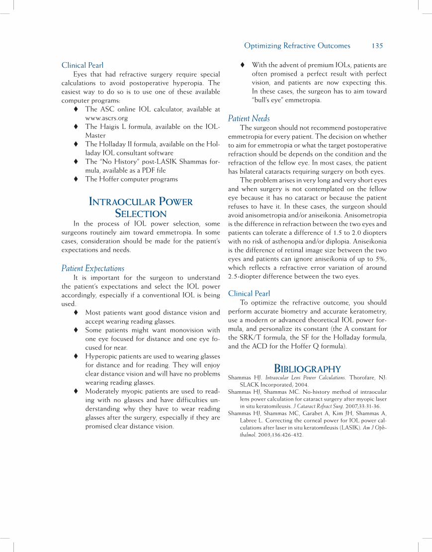
Optimizing Refractive Outcomes 135
Clinical PearlEyes that had refractive surgery require special
calculations to avoid postoperative hyperopia. The easiest way to do so is to use one of these available computer programs: The ASC online IOL calculator, available at
www.ascrs.org The Haigis L formula, available on the IOL-
Master The Holladay II formula, available on the Hol-
laday IOL consultant software The “No History” post-LASIK Shammas for-
mula, available as a PDF file The Hoffer computer programs
Intraocular Power selectIon
In the process of IOL power selection, some surgeons routinely aim toward emmetropia. In some cases, consideration should be made for the patient’s expectations and needs.
Patient ExpectationsIt is important for the surgeon to understand
the patient’s expectations and select the IOL power accordingly, especially if a conventional IOL is being used. Most patients want good distance vision and
accept wearing reading glasses. Some patients might want monovision with
one eye focused for distance and one eye fo-cused for near.
Hyperopic patients are used to wearing glasses for distance and for reading. They will enjoy clear distance vision and will have no problems wearing reading glasses.
Moderately myopic patients are used to read-ing with no glasses and have difficulties un-derstanding why they have to wear reading glasses after the surgery, especially if they are promised clear distance vision.
With the advent of premium IOLs, patients are often promised a perfect result with perfect vision, and patients are now expecting this. In these cases, the surgeon has to aim toward “bull’s eye” emmetropia.
Patient NeedsThe surgeon should not recommend postoperative
emmetropia for every patient. The decision on whether to aim for emmetropia or what the target postoperative refraction should be depends on the condition and the refraction of the fellow eye. In most cases, the patient has bilateral cataracts requiring surgery on both eyes.
The problem arises in very long and very short eyes and when surgery is not contemplated on the fellow eye because it has no cataract or because the patient refuses to have it. In these cases, the surgeon should avoid anisometropia and/or aniseikonia. Anisometropia is the difference in refraction between the two eyes and patients can tolerate a difference of 1.5 to 2.0 diopters with no risk of asthenopia and/or diplopia. Aniseikonia is the difference of retinal image size between the two eyes and patients can ignore aniseikonia of up to 5%, which reflects a refractive error variation of around 2.5-diopter difference between the two eyes.
Clinical PearlTo optimize the refractive outcome, you should
perform accurate biometry and accurate keratometry, use a modern or advanced theoretical IOL power for-mula, and personalize its constant (the A constant for the SRK/T formula, the SF for the Holladay formula, and the ACD for the Hoffer Q formula).
BIBlIograPhyShammas HJ. Intraocular Lens Power Calculations. Thorofare, NJ:
SLACK Incorporated; 2004.Shammas HJ, Shammas MC. No-history method of intraocular
lens power calculation for cataract surgery after myopic laser in situ keratomileusis. J Cataract Refract Surg. 2007;33:31-36.
Shammas HJ, Shammas MC, Garabet A, Kim JH, Shammas A, Labree L. Correcting the corneal power for IOL power cal-culations after laser in situ keratomileusis (LASIK). Am J Oph-thalmol. 2003;136:426-432.

136 Chapter 16
Part B:Limbal Relaxing Incisions
Eric Donnenfeld, MD, and Renée Solomon, MD
While the absence of operative complications is the traditional benchmark by which most of us evalu-ate the success of our surgical efforts, our patients tend to measure the success of their cataract procedures by the quality of their uncorrected visual acuity. Meeting the needs and heightened expectations of our patients today is a challenge that we cannot ignore and, like it or not, each of us must now view cataract surgery as a refractive procedure. Achieving an optimal refractive outcome requires attention to detail and necessitates both precise biometry and careful management of astigmatic errors.
Regular corneal astigmatism decreases uncor-rected visual acuity through meridional blur as one axis of the cornea, steeper than the other, causes image distortion (Figure 16-3). Astigmatism of as little as 0.50 diopters may result in glare, symptomatic blur, ghost-ing, and halos.1 Regular astigmatism in most instances is associated with a 90-degree angle between the steep and flat meridians. Regular astigmatism may be characterized as with-the-rule (Figure 16-4A), against-the-rule (Figure 16-4B), and oblique (Figure 16-4C). In general, irregular astigmatism (Figure 16-4D) should not be treated with limbal relaxing incisions (LRIs). There are several different corneal-based options for treating astigmatism including LRIs, excimer laser pho-toablation, and conductive keratoplasty. In general, the reduction of corneal astigmatism with LRIs at the time of surgery is the most cost-effective and convenient approach. IOL patients are often highly sensitive even to minor refractive errors, and in order to achieve the best possible refractive outcome, surgeons must be willing and able to treat small astigmatic errors.
LRIs are corneal incisions placed adjacent to the limbus that are used to relax the steep axis of regular corneal astigmatism while steepening the flat axis. The procedure allows the eye to heal into a more spheri-cal shape (Figure 16-5). There are several advantages of LRIs over astigmatic keratotomy (AK), a similar incisional procedure that is performed more centrally toward the visual axis. The advantages of LRIs over AK includes a reduced tendency to cause axis shift, less irregular astigmatism, a 1:1 coupling ratio, and a reduced likelihood of perforation.
For regular astigmatic errors ranging from 0.5 to 1.5 diopters, LRIs work very well. Patients with more than 1.5 diopters of astigmatism may benefit from LRIs but there is an increased risk of inducing irregular astigmatism. For patients with higher levels of astigma-tism, a LRI may be performed to “debulk” the astig-matic error and an excimer laser photoablation can be performed after IOL implantation for the reduction of the residual refractive error.
LRIs are usually performed during cataract sur-gery for the treatment of pre-existing astigmatism (Figure 16-6). In experienced hands, LRIs may also be performed postoperatively at the slit lamp (Figure 16-7), although the use of an operating microscope is advised for less experienced surgeons.
A number of LRI nomograms are available, and many studies evaluating LRIs have been performed.1-16 LRIs have been shown to result in an average reduction of cylinder by 60%,17 with 79% of patients corrected to less than 1 diopter of cylinder and 59% corrected to less than 0.5 diopter of cylinder. The 60% reduction in cylinder compares favorably with the results achieved using toric IOLs, which result in 58.4% mean reduc-tion in cylinder.18
Many LRI nomograms are adjusted for age and cylinder axis, making them detailed and complex, and giving the impression that the procedure is extremely precise and unforgiving. However, in our experience, this simply is not the case. LRIs are as much an art as a science. For this reason, we have developed a very simple nomogram that works extremely well (Tables 16-1 and 16-2) and is ideal for the novice LRI surgeon. The Donnenfeld nomogram (DONO) is available on the Internet at www.lricalculator.com (Figure 16-8). The online LRI calculator uses vector analysis to calcu-late where to make LRI incisions based on preoperative patient keratometry and the surgeon’s induced astig-matism. The LRI calculator employs the Donnenfeld
Figure 16-3. Figure demonstrates normal cornea(left)shaped likeabasketball inwhichbothaxesare equal and astigmatic cornea (right) shapedlikeafootballinwhichoneaxisissteeperthantheother.
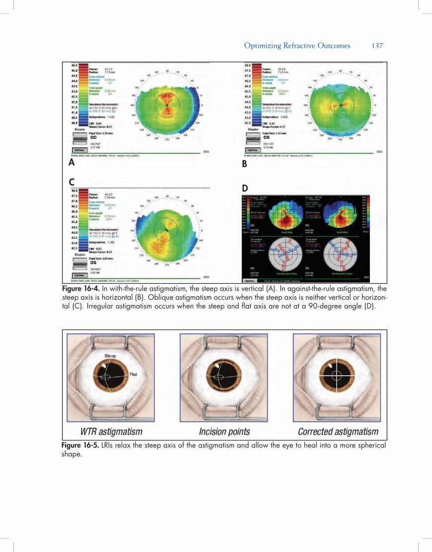
Optimizing Refractive Outcomes 137
Figure 16-4. Inwith-the-ruleastigmatism,thesteepaxisisvertical(A).Inagainst-the-ruleastigmatism,thesteepaxisishorizontal(B).Obliqueastigmatismoccurswhenthesteepaxisisneitherverticalorhorizon-tal(C).Irregularastigmatismoccurswhenthesteepandflataxisarenotata90-degreeangle(D).
Figure 16-5. LRIsrelaxthesteepaxisoftheastigmatismandallowtheeyetohealintoamoresphericalshape.
A
C
B
D
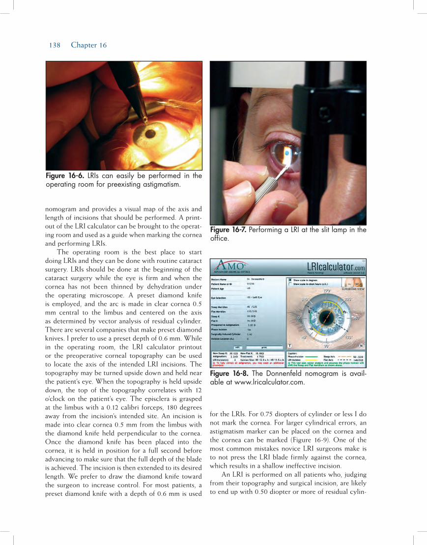
138 Chapter 16
nomogram and provides a visual map of the axis and length of incisions that should be performed. A print-out of the LRI calculator can be brought to the operat-ing room and used as a guide when marking the cornea and performing LRIs.
The operating room is the best place to start doing LRIs and they can be done with routine cataract surgery. LRIs should be done at the beginning of the cataract surgery while the eye is firm and when the cornea has not been thinned by dehydration under the operating microscope. A preset diamond knife is employed, and the arc is made in clear cornea 0.5 mm central to the limbus and centered on the axis as determined by vector analysis of residual cylinder. There are several companies that make preset diamond knives. I prefer to use a preset depth of 0.6 mm. While in the operating room, the LRI calculator printout or the preoperative corneal topography can be used to locate the axis of the intended LRI incisions. The topography may be turned upside down and held near the patient’s eye. When the topography is held upside down, the top of the topography correlates with 12 o’clock on the patient’s eye. The episclera is grasped at the limbus with a 0.12 calibri forceps, 180 degrees away from the incision’s intended site. An incision is made into clear cornea 0.5 mm from the limbus with the diamond knife held perpendicular to the cornea. Once the diamond knife has been placed into the cornea, it is held in position for a full second before advancing to make sure that the full depth of the blade is achieved. The incision is then extended to its desired length. We prefer to draw the diamond knife toward the surgeon to increase control. For most patients, a preset diamond knife with a depth of 0.6 mm is used
for the LRIs. For 0.75 diopters of cylinder or less I do not mark the cornea. For larger cylindrical errors, an astigmatism marker can be placed on the cornea and the cornea can be marked (Figure 16-9). One of the most common mistakes novice LRI surgeons make is to not press the LRI blade firmly against the cornea, which results in a shallow ineffective incision.
An LRI is performed on all patients who, judging from their topography and surgical incision, are likely to end up with 0.50 diopter or more of residual cylin-
Figure 16-6. LRIs can easily beperformed in theoperatingroomforpreexistingastigmatism.
Figure 16-8. The Donnenfeld nomogram is avail-ableatwww.lricalculator.com.
Figure 16-7.PerformingaLRIattheslitlampintheoffice.
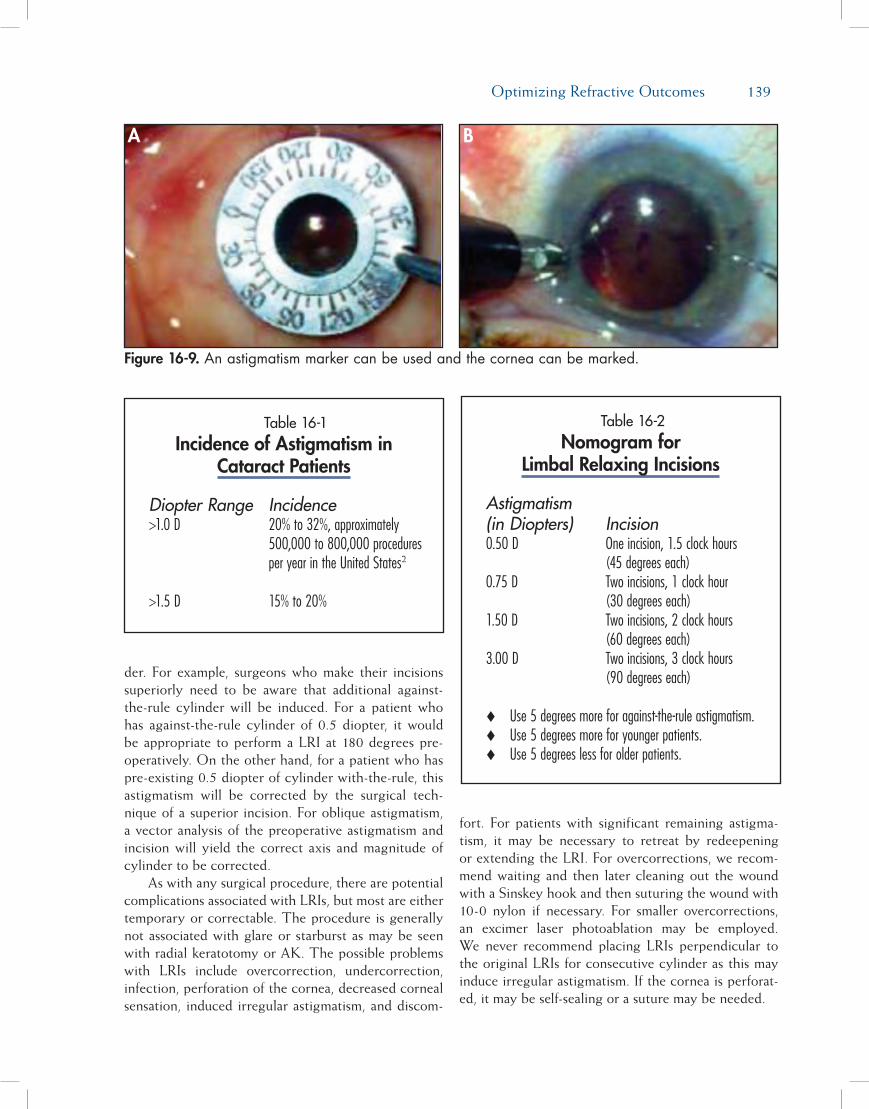
Optimizing Refractive Outcomes 139
der. For example, surgeons who make their incisions superiorly need to be aware that additional against-the-rule cylinder will be induced. For a patient who has against-the-rule cylinder of 0.5 diopter, it would be appropriate to perform a LRI at 180 degrees pre-operatively. On the other hand, for a patient who has pre-existing 0.5 diopter of cylinder with-the-rule, this astigmatism will be corrected by the surgical tech-nique of a superior incision. For oblique astigmatism, a vector analysis of the preoperative astigmatism and incision will yield the correct axis and magnitude of cylinder to be corrected.
As with any surgical procedure, there are potential complications associated with LRIs, but most are either temporary or correctable. The procedure is generally not associated with glare or starburst as may be seen with radial keratotomy or AK. The possible problems with LRIs include overcorrection, undercorrection, infection, perforation of the cornea, decreased corneal sensation, induced irregular astigmatism, and discom-
fort. For patients with significant remaining astigma-tism, it may be necessary to retreat by redeepening or extending the LRI. For overcorrections, we recom-mend waiting and then later cleaning out the wound with a Sinskey hook and then suturing the wound with 10-0 nylon if necessary. For smaller overcorrections, an excimer laser photoablation may be employed. We never recommend placing LRIs perpendicular to the original LRIs for consecutive cylinder as this may induce irregular astigmatism. If the cornea is perforat-ed, it may be self-sealing or a suture may be needed.
Figure 16-9. Anastigmatismmarkercanbeusedandthecorneacanbemarked.
A B
Table 16-1Incidence of Astigmatism in
Cataract Patients
Diopter Range Incidence>1.0 D 20% to 32%, approximately 500,000 to 800,000 procedures per year in the United States2
>1.5 D 15% to 20%
Table 16-2Nomogram for
Limbal Relaxing Incisions
Astigmatism (in Diopters) Incision0.50 D One incision, 1.5 clock hours (45 degrees each)0.75 D Two incisions, 1 clock hour (30 degrees each)1.50 D Two incisions, 2 clock hours (60 degrees each)3.00 D Two incisions, 3 clock hours (90 degrees each)
Use 5 degrees more for against-the-rule astigmatism.Use 5 degrees more for younger patients.Use 5 degrees less for older patients.

140 Chapter 16
Improving refractive outcomes is an important goal for cataract surgeons today and learning to per-form LRIs is a useful step in achieving this end. The good news is that LRIs are not difficult to learn and, when performed properly, they are both predictable and uniformly successful.
reFerences1. Nichamin LD. Nomogram for limbal relaxing incisions. J
Cataract Refract Surg. 2006;32:1048.2. Nichamin LD. Astigmatism control. Ophthalmol Clin North Am.
2006;19:485-493.3. Wang L, Misra M, Koch DD. Peripheral corneal relaxing in-
cisions combined with cataract surgery. J Cataract Refract Surg.2003;29:712-722.
4. Budak K, Friedman NJ, Koch DD. Limbal relaxing incisionswith cataract surgery. J Cataract Refract Surg. 1998;24:503.
5. Gills JP. Treating astigmatism at the time of cataract surgery.Curr Opin Ophthalmol. 2002;13:2-6.
6. Oshika T, Shimazaki J, Yoshitomi F, et al. Arcuate keratom-etry to treat corneal astigmatism after cataract surgery: aprospective evaluation of predictability and effectiveness.Ophthalmology. 1998;105:2012.
7. Maloney WF, Grindle L, Sanders D, et al. Astigmatism con-trol for the cataract surgeon: a comprehensive review ofsurgically tailored astigmatism reduction (STAR). J Cataract Refract Surg. 1989;15:45.
8. Price FW, Greene RB, Marks RG, et al. Astigmatism reduc-tion clinical trial: a multicenter prospective evaluation ofthe predictability of arcuate keratotomy. Arch Ophthalmol.1995;113:277.
9. Devgan U. Corneal correction of astigmatism during cata-
ract surgery. Cataract Refract Surg Today. 2006;7:41-44.10. Tejedor J, Murube J. Choosing the location of corneal inci-
sion based onpreexisting astigmatism in phacoemulsification.Am J Ophthalmol. 2005;139(5):767-776.
11. Kaufmann C, Peter J, Ooi K, et al. Limbal relaxing inci-sions versus on-axis incisions to reduce corneal astigma-tism at the time of cataract surgery. J Cataract Refract Surg.2005;31(12):2261-2265.
12. Muller-Jensen K, Fischer P, Siepe U. Limbal relaxing inci-sions to correct astigmatism in clear corneal cataract surgery.J Refract Surg. 1999;15(5):586-589.
13. Akura J, Matsuura K, Hatta S, Otsuka K, Kaneda S. Anew concept for the correction of astigmatism: full-arc,depth-dependent astigmatic keratotomy. Ophthalmology.2000;107(1):95-104.
14. Faktorovich EG, Maloney RK, Price FW Jr. Effect of as-tigmatic keratotomy on spherical equivalent: results ofthe Astigmatism Reduction Clinical Trial. Am J Ophthalmol.1999;127(3):260-269.
15. Price FW, Grene RB, Marks RG, Gonzales JS. Astigmatismreduction clinical trial: a multicenter prospective evaluationof the predictability of arcuate keratotomy. Evaluation of sur-gical nomogram predictability. ARC-T Study Group. Arch Ophthalmol. 1995;113(3):277-282. Erratum in: Arch Ophthalmol.1995;113(5):577.
16. Oshika T, Shimazaki J, Yoshitomi F, et al. Arcuate keratotomyto treat corneal astigmatism after cataract surgery: a prospec-tive evaluation of predictability and effectiveness. Ophthal-mology. 1998;105(11):2012-2016.
17. Bradley MJ, Coombs J, Olson RJ. Analysis of an approach toastigmatism correction during cataract surgery. Ophthalmo-logica. 2006;220(5):311-316.
18. Package insert. Acrysof ToricTM SA60T4IOL, Alcon Labora-tories, Inc.