achievable throughput optimization in ofdm systems in the
TRANSCRIPT

HAL Id: hal-01010007https://hal.archives-ouvertes.fr/hal-01010007
Submitted on 19 Jun 2014
HAL is a multi-disciplinary open accessarchive for the deposit and dissemination of sci-entific research documents, whether they are pub-lished or not. The documents may come fromteaching and research institutions in France orabroad, or from public or private research centers.
L’archive ouverte pluridisciplinaire HAL, estdestinée au dépôt et à la diffusion de documentsscientifiques de niveau recherche, publiés ou non,émanant des établissements d’enseignement et derecherche français ou étrangers, des laboratoirespublics ou privés.
Achievable Throughput Optimization in OFDM Systemsin the Presence of Interference and its Application to
Power Line NetworksThanh Nhân Vo, Karine Amis Cavalec, Thierry Chonavel, Pierre Siohan
To cite this version:Thanh Nhân Vo, Karine Amis Cavalec, Thierry Chonavel, Pierre Siohan. Achievable ThroughputOptimization in OFDM Systems in the Presence of Interference and its Application to Power LineNetworks. IEEE Transactions on Communications, Institute of Electrical and Electronics Engineers,2014, 62 (5), pp.1705 - 1715. �10.1109/TCOMM.2014.031614.130660�. �hal-01010007�

1
Achievable Throughput Optimization in OFDM
Systems in the Presence of Interference and its
Application to Power Line Networks
Thanh Nhan VO1, Karine AMIS1, Thierry CHONAVEL1, Pierre SIOHAN2
1: Telecom Bretagne / UMR CNRS 6285 Lab-STICC; 2: Orange R&D Labs
Abstract
The aim of this paper is to study the bit-loading and power allocation problem in the presence
of interference (Inter-carrier Interference (ICI) and Inter-Symbol Interference (ISI)) in Orthogonal Fre-
quency Division Multiplexing (OFDM) systems. ISI and ICI significantly degrade the performance of
OFDM systems and make the resource management optimized without the assumption of interference
less efficient. To solve this problem, an initial solution based on the greedy approach is proposed in
this paper. Then, several reduced complexity approaches, which yield a little degradation compared to
the initial solution, have been developed. Simulation results presented in the context of Power Line
Communication (PLC) show that the performance of proposed algorithms is tight with their upper
bound. Moreover, these algorithms efficiently improve the system performance as compared to the
constant power water-filling allocation algorithm as well as maximum power allocation algorithm.
Index Terms
Bit-loading, Power allocation, ICI, ISI, Power Line Communication, Windowed-OFDM, Greedy
Algorithm.
I. INTRODUCTION
In the past decades, the use of PLC systems for high rate indoor broadband communications
has spread rapidly. No-new-wire makes the PLC economically attractive for indoor LAN and
become a complementary technology to wireless technologies such as WLAN [1], [2].
PLC systems exploit the OFDM technique to combat the effect of multi-path channels with
severe frequency selectivity [3], [4]. The conventional OFDM divides the entire bandwidth into
June 10, 2014 DRAFT
2
many orthogonal subcarriers and data are transmitted in parallel over these subcarriers. Therefore,
it can support high transmission data rate and achieves high spectral efficiency. Unfortunately,
many phenomena such as frequency offset between transmitter and receiver, insufficient guard
interval or Doppler frequency shift, etc. induce inter-carrier interference (ICI) as well as inter-
symbol interference (ISI) that significantly degrade the performance of OFDM systems [5], [6]
and make the resource management more complicated. Many techniques have been developed
to combat the effects of ISI and ICI, such as time domain windowing [7], frequency-domain
equalization [8] or ISI and ICI self-cancellation [9].
Both current and next generation of PLC systems employ frequency band from 2 to 30 MHz
(and over), e.g., HPAV1, HPAV2, IEEE P1901, ITU-T G.9963 [2], [10]. In this frequency band,
many radio applications such as amateur radio, urgency and military services have already been
exploited. To avoid interference with those systems, a spectral mask is specified for PLC systems
[10]. The IEEE P1901 standard uses the Windowed-OFDM instead of the conventional OFDM
technique to adapt to the spectral mask [10]. In [11], the HS-OQAM is proposed for future use
to increase the data rate as well as adapt to new spectral masks in Europe.
Regarding resource allocation, the bit-loading can be designed to achieve different objectives
in OFDM systems, such as bit allocation, power allocation, code rate adaptation, etc. Different
algorithms have been proposed among which we can enumerate: adaptive-rate algorithms which
maximize the capacity under the power and bit-error rate constraints (BER) [12], [13]; margin-
adaptive algorithms which minimize the consumed power under data rate and BER constraints
[14]; BER minimization under data rate and power constraints [15]. If the ISI and ICI are present,
the system can be modeled as a Gaussian interference channel [16]. In this case, by using joint
coding and decoding, the system capacity is maximized by using the water-filling algorithm
derived in [16]. In the absence of joint coding and decoding, the interference is considered as
noise when solving the resource allocation problem [17], [18], [19], [20], [21]. In [18], the
achievable throughput of PLC systems is maximized by combining the bit-loading algorithm
and adaptive cyclic prefix. The bit-loading algorithm used in [18] relies on two simplifying
assumptions. First, the conventional OFDM is taken into account to calculate ISI and ICI in
PLC systems while, as mentioned above, PLC systems exploit the Windowed-OFDM instead
of the conventional OFDM. The second simplification is enabled by on/off power loading and
integer bit number constraint. The latter leads to bit discretization that causes non optimal power
DRAFT June 10, 2014
3
use. Actually, the discretized bit-loading can be achieved with lower power consumption than
with the approach in [18] and the residual power could be exploited to increase data rate or/and
transmission quality. CP design for maximizing the achievable throughput for Windowed-OFDM
systems is considered in [22]. Unfortunately, the power allocation strategy in [22] is also non
optimal due to the bit discretization. In [18], [22], it is shown that the choice of a cyclic prefix
(CP) length equal to the channel impulse response length makes PLC systems less efficient
in terms of achievable throughput. Shorter CP evidently results in ISI and ICI, but the gain
offered by shortened CP may exceed the losses caused by interference. Another approach to
CP length adaptation relies on the statistical channel state information as derived in [23], [24].
This approach causes a capacity loss when compared to the bit and power allocation with the
instantaneous channel state information (CSI). In our paper, we assume that perfect instantaneous
CSI is available and we use it to optimize the resource allocation. Moreover, our interest is to
optimize the throughput for fixed GI length and we take into account possible interference in
the bit/power allocation.
Recently, several approaches to search for the upper-bound of the achievable throughput have
been studied in [19] but no practical solution of the achievable throughput maximization problem
with low-complexity has been given. A solution based on the greedy approach has been developed
in [25] for the multi-carrier interference channel in multi-users ADSL systems. However, it
only takes into account the ICI caused by the asynchronous cross-talk effect. Moreover, due
to the difficulty of exact additional power computation, the algorithm in [25] exploits the
gradient information to approximate the power adjustment when modifying the number of bits
on subcarriers. The algorithm detailed in [25] approximates the matrix inversion via power series
expansion to reduce the complexity. This method works only if the assumption of convergence
of the power series expansion is valid. In this paper, we focus on single-user Windowed-OFDM-
based systems in the presence of ICI as well as ISI. Our proposed algorithms are also based on the
greedy principle, which is detailed in the section III. However, a judicious iterative procedure
for accurate matrix inversion calculation and an iterative bit-loading procedure exploiting the
incremental power needed to transmit an additional bit are utilized instead of the approximations
proposed in [25].
The main contribution of this paper is to use the greedy principle to solve the achievable
throughput maximization problem in PLC systems in the presence of interference and under
June 10, 2014 DRAFT

4
power and bit-error rate constraints. For this purpose, the ISI and ICI due to the presence of
insufficient cyclic prefix in PLC systems have been analyzed. Relying on the ISI and ICI analysis
and the greedy principle, we propose an initial greedy algorithm to calculate the achievable
throughput maximization in the presence of ISI and ICI. Then, several approaches are proposed
in order to reduce the complexity with a negligible degradation compared to the initial greedy
solution.
The rest of the paper is organized as follows. In Section II, the OFDM model in the presence
of ISI and ICI is described. In Section III, the greedy principle and several approaches to reduce
the complexity are presented. In Section IV, the achievable throughput maximization problem
is formulated and an initial solution, which exploits the greedy principle is given. A reduced
complexity algorithm is also proposed. Numerical results are reported in Section V. Finally,
conclusions and perspectives are drawn in Section VI.
II. SYSTEM MODEL
Let us consider a Windowed-OFDM system with L subcarriers used out of M , which are
activated under a given spectral mask constraint. The demodulated sample on the m0-th used
subcarrier and n0-th OFDM symbol is given by
y(m0, n0) = α(m0, n0)cm0,n0 + ICI(m0, n0) + ISI(m0, n0) + b(m0, n0), (1)
where α(m0, n0), cm0,n0 , ISI(m0, n0), ICI(m0, n0), b(m0, n0) denote the channel multiplicative
factor, the symbol of interest, the ISI and ICI coefficients and the complex circularly Gaussian
noise sample at the m0-th used subcarrier and n0-th OFDM symbol.
We assume that the channel is block-based time invariant. Without loss of generality and for
the sake of simplicity, in a block of many OFDM symbols, Eq. (1) can be re-written as
y(m0) = α(m0)cm0 + ICI(m0) + ISI(m0) + b(m0) (2)
Since the number of subcarriers used in practical PLC systems is quite large, we assume that the
interference on a given subcarrier is normally distributed (following the central limit theorem)
[3], [26]. Different normality tests for the interference have been introduced in [3]. These tests
have confirmed the validity of gaussian distribution of the interference in practical PLC systems.
DRAFT June 10, 2014

5
Then, the signal to interference plus noise ratio (SINR) and the theoretical capacity on the m0-th
used subcarrier are given as follows:
SINR(m0) =|α(m0)|
2P (m0)
PICI(m0) + PISI(m0) + σ2b (m0)
(3)
C(m0) = log2
(
1 +SINR(m0)
Γ
)
(4)
where P (m0) is the power allocated to m0-th used subcarrier and Γ is the SNR gap that models
the practical modulation and coding scheme for a targeted symbol-error rate (SER):
Γ =1
3
[
Q−1
(SER
4
)]2
(5)
where Q−1(x) is the inverse tail probability of the standard normalization distribution [27].
Let us denote Ause the set of used subcarriers, then #(Ause) = L, where # denotes the
cardinality of Ause. On a given subcarrier, the interference power generally depends on the
power allocated to other used subcarriers (see Appendix) and can be written as
PI(m0) = PICI(m0) + PISI(m0) =L∑
m=1
W (m0,m)P (m) (6)
where W (m0,m) is the interference contribution of the m-th used subcarrier on the m0-th used
subcarrier. In other words, W (m0,m) is the interference contribution of the m-th entry of Ause
on the m0-th entry of Ause.
Let W denote the interference matrix with entry (a,b) equal to W (a, b) for a, b ∈ {1, ..., L}.
Let P denote the allocated power vector and N the noise power vector. The total interference
power and the SINR on the m0-th used subcarrier are given by
PI(m0) = [WP](m0) (7)
SINR(m0) =|α(m0)|
2P (m0)
PI(m0) +N(m0)(8)
III. GREEDY PRINCIPLE AND REDUCED COMPLEXITY APPROACHES
In this section, we present the greedy principle for the discrete bit-loading problem. Hereafter,
only the active subcarriers are taken into account except in the Appendix.
June 10, 2014 DRAFT

6
A. Greedy principle to solve the bit-loading problem
Let B, A, Q and C denote the bit-allocation vector, the allowable set of numbers of bits
that correspond to available modulations on subcarriers, the objective function and the set of
constraints (power constraints, data rate constraints, BER constraints). As Q and C depend on
B, the corresponding optimization problem can be written as
Q(B); B ∈ AL, C(B) (9)
An algorithm is said to be greedy if every decision taken at any stage is the one with the most
obvious immediate advantage. That is to say it makes a locally optimal choice in the hope that
successive choices will lead to a globally optimal solution. Generally, a greedy algorithm does
not produce a global optimum, but nonetheless it may yield a local optimum that approximate
well a global optimum [28].
In practice, the standard greedy algorithm initializes vector B = {b(m)}m=1,..,L to the null
vector. Another way to initialize the bit-loading vector relies on the water-filling and the bit
discretization. This approach has been exploited in [29]. In [29], it is shown that the use of
this initialization in the interference-free systems can strongly reduce the complexity with a
negligible throughput loss when compared to the standard greedy algorithm. Then, the greedy
process successively increases the number of bits on the subcarriers up to its upper level in A,
according to a predefined cost function F , which enables to optimize Q. The cost function is
practically defined according to the objective function and taking into account the constraints.
For example, for the throughput maximization problem under the total power constraint, the cost
function is defined as the required upgrade power [30], [31] or as the gradient information in
[25] or as the metrics of log-likelihood ratios (LLRs) for the throughput maximization under the
BER constraint [32]. Generally, the cost function values depend on the subcarrier index and the
iteration. We denote by F(m, k) the cost function value associated to an increase of the number
of bits on the m-th subcarrier at the k-th iteration. At the k-th iteration, the greedy principle
evaluates F(m, k) for all values of m and decides which subcarrier will be allocated additional
bits. The number of bits on the m0-th subcarrier, i.e. b(m0), is increased after k-th iteration if
m0 = argminm
F(m, k), ∀m ∈ [1, L]
C(B)(10)
DRAFT June 10, 2014

7
From (10), even if F(m0, k) is the minimum value of F(m, k), if there exists any unsatisfied
constraint, then the number of bits allocated to the subcarrier cannot be increased. In this case,
to avoid meaningless loops, the cost function F(m0, k) is set to infinity and this subcarrier must
not be considered for additional bits allocation in following iterations. The procedure stops if
there is no subcarrier left to allocate additional bits.
B. Reduced complexity approaches
In many cases, although the use of the greedy principle described in Section III-A yields an
efficient solution to the problem in Eq. (9), its high complexity makes it unfeasible in practice.
Since the complexity depends on the computational effort to calculate the cost function and the
number of iterations, it can be reduced in particular by using computationally less expensive
approximation of the cost function. On the other hand, the number of iterations depends on
the bit-loading vector initialization and the number of simultaneously increased subcarriers per
iteration. Thus, the number of iterations can be reduced by choosing a judicious initial bit-loading
vector instead of a null vector and by simultaneously processing several subcarriers per iteration.
We will see that these modifications lead to reduced complexity approaches at the expense of
a little degradation compared to the greedy solution. In the next sections, the greedy principle
and the reduced complexity approaches are utilized to form a reduced complexity algorithm that
closely solves the achievable throughput maximization problem in single-user Windowed-OFDM
systems in the presence of ISI and ICI. In the simulation part, this algorithm is applied in the
context of PLC systems.
IV. ACHIEVABLE THROUGHPUT OPTIMIZATION IN THE PRESENCE OF INTERFERENCE
The achievable throughput optimization problem is difficult when taking into account ISI and
ICI. In fact, even with the continuous bit allocation relaxation, the rate-adaptive problem in the
presence of ISI and ICI cannot be easily solved because the term P (m), which is the power
allocation on the m-th subcarrier, exists both in the numerator as well as in the denominator of
the throughput calculation formula (see Eq. (3), (4)). In [31] the solutions for both continuous
and discrete bit-loading in the presence of ICI are determined. Nevertheless, the proposed bit-
adding algorithm with null initial bit-loading vector for the discrete bit-loading remains highly
complex. In [17], the power allocation corresponding to the continuous bit-loading optimization
June 10, 2014 DRAFT
8
is derived. It indicates that the mutual in-out information is not a convex function of the input
power distribution and that the optimal solution must be obtained via an exhausive search that
is equivalent to an NP-hard problem. In the simulation part, we give an illustration of the non-
convexity of the mutual information.
Let A be the allowable set of number of bits associated to allowable modulations specified
by the standard and Td be the down discretization function defined as
Td (R+ → A) : x → max{T ∈ A : T ≤ x} (11)
Then, the achievable throughput optimization problem under the power constraints in single-
user Single Input Single Output (SISO)-OFDM systems can be expressed as (12). The second
constraint in (12) is to satisfy a given spectral mask. Problem (12) closely resembles the multi-
user power control problem in digital subscriber lines (DSL) systems. The multi-user power
control can be solved by the optimal spectrum balancing (OSB) [33], [34] and the iterative
spectrum balancing (ISB) [34], [35], which decompose the initial problem into smaller problems
corresponding to each subcarrier.
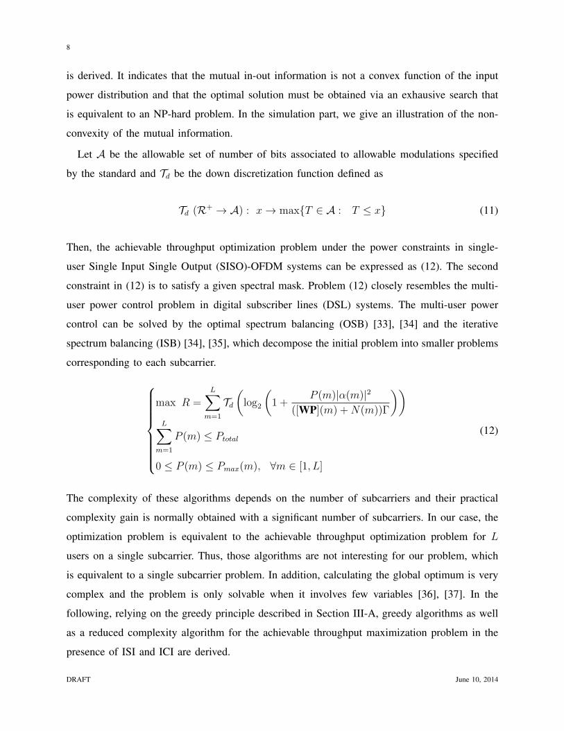
max R =L∑
m=1
Td
(
log2
(
1 +P (m)|α(m)|2
([WP](m) +N(m))Γ
))
L∑
m=1
P (m) ≤ Ptotal
0 ≤ P (m) ≤ Pmax(m), ∀m ∈ [1, L]
(12)
The complexity of these algorithms depends on the number of subcarriers and their practical
complexity gain is normally obtained with a significant number of subcarriers. In our case, the
optimization problem is equivalent to the achievable throughput optimization problem for L
users on a single subcarrier. Thus, those algorithms are not interesting for our problem, which
is equivalent to a single subcarrier problem. In addition, calculating the global optimum is very
complex and the problem is only solvable when it involves few variables [36], [37]. In the
following, relying on the greedy principle described in Section III-A, greedy algorithms as well
as a reduced complexity algorithm for the achievable throughput maximization problem in the
presence of ISI and ICI are derived.
DRAFT June 10, 2014

9
A. Bit number – Power level relation
Firstly, we do not consider any constraint on the power allocated on each subcarrier and we
search the solution for the following problem: given B = [b(1), b(2), . . . , b(L)]T the vector of
number of bits allocated to subcarriers, we find the power vector P = [P (1), P (2), . . . , P (L)]T
so that:
log2
(
1 +P (m)|α(m)|2
([WP](m) +N(m))Γ
)
= b(m), ∀m ∈ [1, L] (13)
Let us noteP (m)
[WP](m) +N(m)=
(2b(m) − 1))Γ
|α(m)|2= λm (14)
Then, re-writting Eq. (14) in the matrix form, we obtain:
P = Λ(B)WP +Λ(B)N
⇒ P = (I −Λ(B)W)−1Λ(B)N (15)
where Λ(B) = diag(λ1, ..., λL). Equation (15) yields the solution of problem (13) alone without
the constraints imposed on the power allocated to the subcarriers. However, power constraints
always exist, i.e. 0 ≤ P (m) ≤ Pmax(m), then there are many cases where we can’t find the
power allocation corresponding to a given bit allocation and satisfying the set of constraints.
The monotonicity of the right-hand side of (15) has been already demonstrated in [25] where it
is shown that if B1 ≤ B2 component-wise, then the corresponding power vectors satisfy P1 ≤ P2
component-wise. It means that when the number of bits on a subcarrier is increased, the resulting
power levels on all subcarriers are higher than or equal to the current ones.
B. Greedy Algorithm
The standard greedy algorithm initializes B = 0, that is to say Λ = 0 and P = 0. Then it tries
to successively increase the number of bits on the m-th subcarrier to its upper level according to
the cost function F and derives the allocated power by using (15). However, the difficulty of cost
function construction causes the complicated implementation to this algorithm. The search for a
relevant cost function for an optimal greedy algorithm is a complex problem because for every
number of bits increase on any subcarrier, the power levels on all subcarriers must be changed
to account for the increased interference. As mentioned above, both power constraints, i.e. total
allocated power and spectral mask constraint, have to be taken into account to define the cost
June 10, 2014 DRAFT

10
function. In this paper, for the sake of simplicity, we only take into account the incremental power
needed to transmit an additional bit as the cost function in our proposed solutions. This cost
function has been utilized to solve efficiently the achievable throughput maximization problem
in OFDM systems under the total power constraint [30], [31], [29]. The greedy-based algorithms
such as the bit-adding (or bit-filling) and bit-subtracting (or bit-removal) are pratically utilized
to derive feasible solutions in many bit-loading optimization problems [32], [38], [39].
1) Standard Algorithm: Let us denote by Pk the power allocation and by Λk the corresponding
matrix (Eq. (14)) after iteration k. For an additional number of bits on the m-th subcarrier, Λ(m)k+1
and P(m)k+1 denote the new matrix and power allocation vector updated accordingly. Let tr(A)
denote the trace of vector A. Then, the incremental power needed to transmit an additional bit
on the m-th subcarrier at iteration (k + 1), is chosen as a cost function and defined by
F(m, k + 1) = ∆Pbit(m, k + 1) =tr(P
(m)k+1 − Pk)
∆b(m)k+1
(16)
The number of bits on the m0-th subcarrier is increased at iteration (k+1) to its upper level in
A if
m0 = argminm
∆Pbit(m, k + 1)
tr(P(m0)k+1 ) ≤ Ptotal
0 ≤ P(m0)k+1 (m) ≤ Pmax(m), ∀m ∈ [1, L]
(17)
After updating the number of bits on the m0-th subcarrier, Λ and P become:
Λk+1 = Λ(m0)k+1 ; Pk+1 = P
(m0)k+1 (18)
As in Section III, the procedure is repeated until there is no subcarrier left to allocate additional
bits.
The complexity of this standard algorithm is high. Let us denote by Ak+1on the set of subcarriers
to which we can allocate additional bits at iteration (k + 1) and Lk+1on = #(Ak+1
on ) (≤ L). At
iteration (k+1), Lk+1on matrices of size LxL must be inverted to derive P
(m)k+1 ∀m ∈ Ak+1
on . Hence,
the complexity is about O(L3 ∗ Lk+1on ) due to the matrix inversions for minimum search. This
algorithm becomes intractable as the number of subcarriers becomes significant.
DRAFT June 10, 2014

11
2) Efficient computation of the cost function: The complexity of the standard greedy algorithm
is mainly due to matrix inversions in the cost function calculation. To reduce the complexity, an
efficient method is proposed to solve the matrix inversion problem. From Eq. (15),
Pk = (I −ΛkW)−1ΛkN = MkΛkN (19)
At the iteration (k + 1), if the bit allocation on the m-th subcarrier is increased by ∆b(m)k+1, then
∆λ(m)k+1 =
(2bk(m)+∆b(m)k+1 − 2bk(m))Γ
|α(m)|2(20)
Λ(m)k+1 = Λk +∆λ
(m)k+1eme
Tm (21)
P(m)k+1 = (I −Λ
(m)k+1W)−1
Λ(m)k+1N (22)
where em is a column vector that has m-th entry equal to 1 and the others equal to 0. Letting
M(m)k+1 = (I −Λ
(m)k+1W)−1, we obtain:
M(m)k+1 = (I −Λ
(m)k+1W)−1
= (I −ΛkW −∆λ(m)k+1em e
TmW︸ ︷︷ ︸
Wm
)−1
= (M−1k − em∆λ
(m)k+1Wm)
−1
= Mk +MkemWmMk
1
∆λ(m)k+1
− WmMkem
= Mk +∆M(m)k+1 (23)
P(m)k+1 = M
(m)k+1Λ
(m)k+1N (24)
Note that M0 = I because B = 0 or equivalently Λ0 = 0 at the first iteration. At any iteration,
we can derive the power vector P(m)k+1 when the number of bits on m-th subcarrier is increased.
We choose the m0-th subcarrier to increase its number of bits as in Eq. (17). Finally, matrix M,
the power vector and the bit-allocation corresponding matrix are updated to
Mk+1, Pk+1, Λk+1 = M(m0)k+1 , P
(m0)k+1 , Λ
(m0)k+1 (25)
Due to the simple expression of em, the complexity of ∆M(m)k+1 calculation is only O(2L2). Thus,
the total complexity at iteration (k+1) of this algorithm is O(4L2 ∗Lk+1on ), i.e. O(3L2 ∗Lk+1
on ) to
calculate M(m)k+1, O(L2 ∗Lk+1
on ) to calculate P(m)k+1 for all the values of m. Finally, the complexity
is reduced by a factor of about L/4 thanks to the proposed implementation of matrix inversion.
June 10, 2014 DRAFT

12
In the following, the greedy algorithm which uses this computation is called the proposed
greedy algorithm and referred to as GR to distinguish from the standard greedy algorithm
(Standard GR), which exploits the matrix inversion to calculate the cost function.
C. Reduced complexity approaches
In this section, we try to reduce the total complexity of the greedy algorithms by relying on
the reduced complexity approaches proposed in Section III-B.
1) Cost function approximation: to further reduce total complexity, an approximation of the
incremental power needed to transmit an additional bit on m-th subcarrier is proposed. By using
Eq. (15), we obtain:
Pk −ΛkWPk = ΛkN
P(m)k+1 −Λ
(m)k+1WP
(m)k+1 = Λ
(m)k+1N
(26)
Letting ∆P(m)k+1 = P
(m)k+1 − Pk and ∆Λ
(m)k+1 = ∆λ
(m)k+1eme
Tm, the difference of equations in (26)
yields
∆P(m)k+1 −ΛkW∆P
(m)k+1 −∆Λ
(m)k+1WPk −∆Λ
(m)k+1W∆P
(m)k+1 = ∆Λ
(m)k+1N (27)
We assume that ∆Λ(m)k+1WPk >> ∆Λ
(m)k+1W∆P
(m)k+1 or equivalently [WPk](m) >> [W∆P
(m)k+1](m),
i.e. the interference increase on each subcarrier due to the increase of power allocation is
negligible as compared to the current interference level on this subcarrier. This assumption
is valid when the power allocation becomes high. In our simulations, it is valid with significant
probability (>90%). Then, we can approximate ∆P(m)k+1 from Eq. (27) as
∆P(m)k+1 ≈ (I −ΛkW)−1∆Λ
(m)k+1(WPk + N) ≈ Mk∆λ
(m)k+1(WPk + N) (28)
The required power per additional bit on m-th subcarrier is
∆Pbit(m, k + 1) =tr(∆P
(m)k+1)
∆b(m)k+1
≈tr(Mk(:,m))∆λ
(m)k+1[WPk + N](m)
∆b(m)k+1
(29)
where Mk(:,m) is the m-th column vector of matrix Mk. Note that the matrix inversion in the
calculation of ∆Pbit(m, k + 1) has already been calculated to derive Pk:
Pk = (I −ΛkW)−1ΛkN = MkΛkN (30)
DRAFT June 10, 2014

13
Then, at every iteration, the number of matrix inversions to calculate is only one. Thus the
complexity reduction gain at iteration (k + 1) is of about Lk+1on as compared to the standard
greedy algorithm.
2) Reduction of the number of iterations: The choice of null initial bit-allocation vector
B = 0 or equivalently P = 0 and Λ = 0 involved by the greedy approach makes the number
of iterations high. We can enhance the convergence rate by judiciously initializing vector B.
An initial bit-loading vector that can be utilized is the bit-loading solution obtained by the
water-filling followed by bit discretization. In other words, the power allocation obtained by the
Constant Power Water-Filling (CPWF) [17] is used to calculate the continuous bit-loading. From
the CPWF solution we perform the discrete bit-loading and we determine the corresponding
power allocation applying (15). It is exploited to judiciously initialize bit-loading and power
allocation vectors.
Theorem 1. The power allocation corresponding to the bit-loading initialized by CPWF algo-
rithm followed by bit discretization always satisfies the power constraints.
Proof. Let CCPWF and PCPWF be the continuous bit-loading and power allocation vectors ob-
tained by the CPWF algorithm; B0 and P0 be the discrete bit-loading vector and its corresponding
power allocation vector after the discretization and from the monotonicity of the right-hand side
of (15) (see VI.A), we obtain:
0 ≤ B0 ≤ CCPWF ⇒ 0 ≤ P0 ≤ PCPWF (31)
or equivalently,
0 ≤ P0(m) ≤ PCPWF (m) ≤ Pmax(m), ∀mL∑
m=1
P0(m) ≤L∑
m=1
PCPWF (m) = Ptotal
(32)
This demontrates that P0 satisfies the power constraints.
In the simulations, it is shown that the performance obtained by choosing the initial bit-
loading vector obtained by the water-filling and bit discretization is slightly different from the one
obtained by choosing a null one. The proposed greedy algorithm combined with this initialization
is referred to as GR + Init in the simulations.
For further complexity reduction, we tried to simultaneously increase the number of bits on K
June 10, 2014 DRAFT

14
subcarriers per iteration corresponding to the K minimum values of the cost function instead of
only one subcarrier per iteration as in the previous approaches. At any iteration, if the number
of bits on K subcarriers cannot be increased simultaneously, then we try to increase them one
by one.
3) Proposed reduced complexity algorithm: Applying the above reduced complexity ap-
proaches results in a reduced complexity algorithm (RCA). The initial discrete bit-loading vector
obtained by the CPWF followed by bit discretization algorithm, the cost function approxima-
tion and the simultaneous increase of K subcarriers per iteration are utilized in this proposed
algorithm. The average complexity per iteration is dominated by matrix inversion computation.
Let Lon = βL, (0<β<1) be the average number of subcarriers that can be allocated additional
bits at each iteration, i.e. Lon = 1N
∑N−1k=0 Lk
on, where N is the number of iterations. To illustrate
the total complexity, the equivalent number of matrix inversions is calculated by normalizing the
total complexity with the complexity of inversion matrix (the complexity of a matrix inversion is
O(L3)). The complexity per iteration, the number of iterations and the equivalent total number
of matrix inversions are shown in Table 1 where β1 < β.
Complexity Number of Number
Algorithm per iteration iterations of matrix
inversions
Standard GR ≈ O(βL4) Ns Ns ∗ O(βL)
GR ≈ O(4βL3) Ns Ns ∗ O(4β)
GR + Init ≈ O(4β1L3) N1 << Ns N1 ∗ O(4β1)
RCA ≈ O(L3) NK << Ns NK ∗ O(1)
Table 1. Complexity per iteration, number of iterations and equivalent total number of matrix
inversions.
D. The convergence of the algorithms
All algorithms studied in this paper always converge. The proof of this convergence relies on
the monotonicity of the right-hand side of (15) and bit number increment in the Greedy process.
The initial power allocation vector always satisfies the power constraints. At every iteration, we
try to increase the number of bits on the subcarriers or equivalently, to setup a new bit-loading
DRAFT June 10, 2014
15
vector that is greater (component wise) when compared to the current bit-loading vector. This
leads to the increase of power allocation vector. However, the constrained area of the power
allocation vector is bounded. Hence, all proposed algorithms converge to a final state, which
depends on the initial bit-loading vector and the way the subcarriers are chosen at every iteration.
V. SIMULATIONS RESULTS
The simulation parameters are given as follows:
• Single-user SISO-PLC system with the IEEE P1901 standard.
• Ts = 0.01 (µs), T0 = 40.96 (µs) (IEEE P1901 standard).
• GI = 5.56 (µs), RI = 4.96 (µs) (IEEE P1901 standard).
• A = {0, 1, 2, 3, 4, 6, 8, 10, 12}.
• Pmax(m) = 1 (normalized to the spectral mask at Pmask = -55 dBm/Hz), ∀m ∈ [1, L].
• Γ = 4.038, corresponding to SER = 10−3.
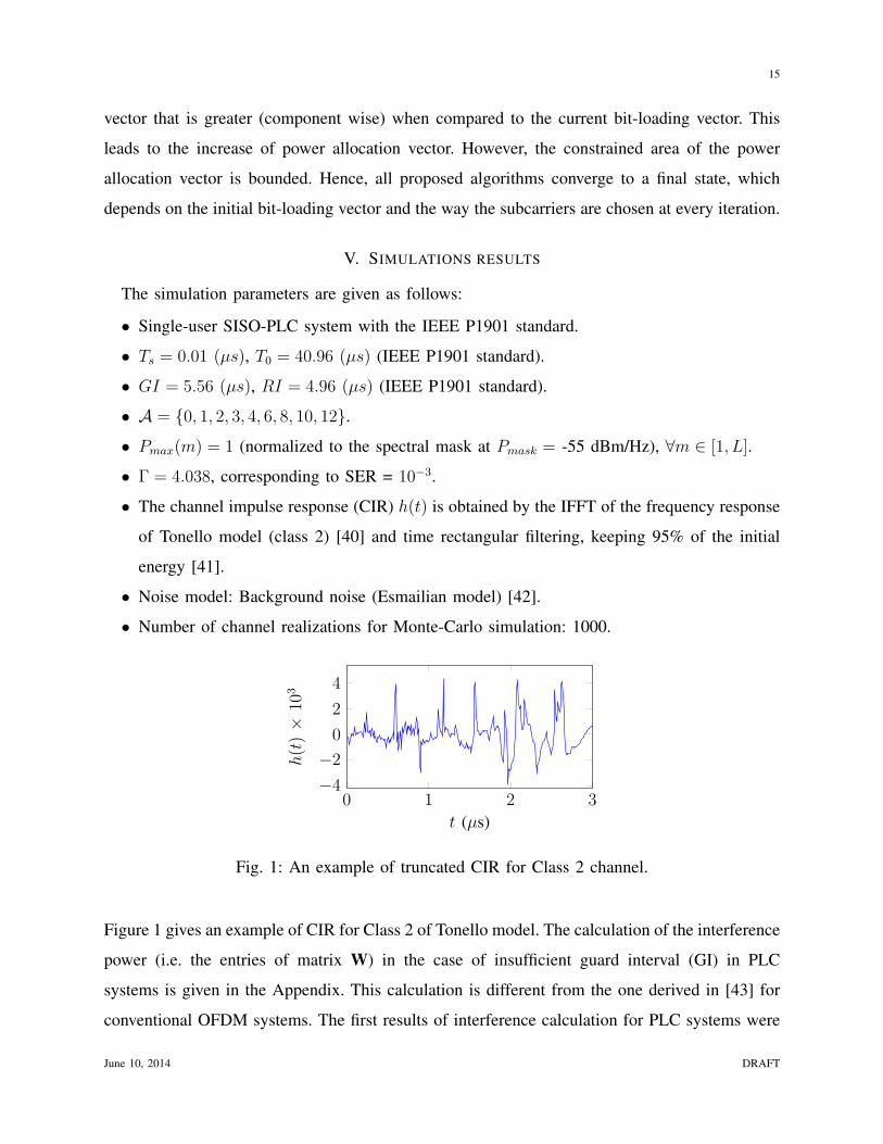
• The channel impulse response (CIR) h(t) is obtained by the IFFT of the frequency response
of Tonello model (class 2) [40] and time rectangular filtering, keeping 95% of the initial
energy [41].
• Noise model: Background noise (Esmailian model) [42].
• Number of channel realizations for Monte-Carlo simulation: 1000.
0 1 2 3−4
−2
0
2
4
t (µs)
h(t)×
103
Fig. 1: An example of truncated CIR for Class 2 channel.
Figure 1 gives an example of CIR for Class 2 of Tonello model. The calculation of the interference
power (i.e. the entries of matrix W) in the case of insufficient guard interval (GI) in PLC
systems is given in the Appendix. This calculation is different from the one derived in [43] for
conventional OFDM systems. The first results of interference calculation for PLC systems were
June 10, 2014 DRAFT
16
0 5 · 10−2 0.1 0.15 0.2 0.25 0.3 0.35 0.454
56
58
60
62
P0 (Normalized)
Cap
acit
yC
(Mbps)
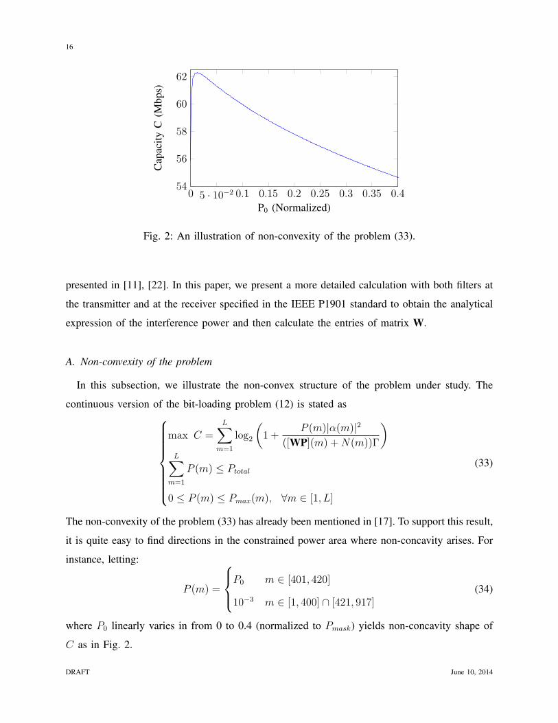
Fig. 2: An illustration of non-convexity of the problem (33).
presented in [11], [22]. In this paper, we present a more detailed calculation with both filters at
the transmitter and at the receiver specified in the IEEE P1901 standard to obtain the analytical
expression of the interference power and then calculate the entries of matrix W.
A. Non-convexity of the problem
In this subsection, we illustrate the non-convex structure of the problem under study. The
continuous version of the bit-loading problem (12) is stated as
max C =L∑
m=1
log2
(
1 +P (m)|α(m)|2
([WP](m) +N(m))Γ
)
L∑
m=1
P (m) ≤ Ptotal
0 ≤ P (m) ≤ Pmax(m), ∀m ∈ [1, L]
(33)
The non-convexity of the problem (33) has already been mentioned in [17]. To support this result,
it is quite easy to find directions in the constrained power area where non-concavity arises. For
instance, letting:
P (m) =
P0 m ∈ [401, 420]
10−3 m ∈ [1, 400] ∩ [421, 917](34)
where P0 linearly varies in from 0 to 0.4 (normalized to Pmask) yields non-concavity shape of
C as in Fig. 2.
DRAFT June 10, 2014
17
0 20 40 60 80 1008
10
12
14
Max Total Power (Normalized)
Ach
ieved
Thro
ughput
(Mbps)
Upper bound
MPA (continuous)
CPWF (continuous)
CPWF (discretized)
Greedy
Greedy + Init
RCA (K=1)
MPA (discretized)13.46
13.48
13.5
13.52
13.54
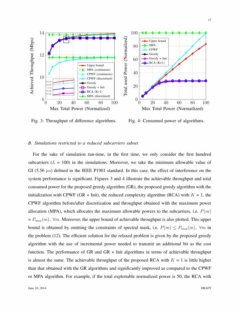
Fig. 3: Throughput of difference algorithms.
0 20 40 60 80 1000
20
40
60
80
100
Max Total Power (Normailized)
Tota
luse
dP
ow
er(N
orm
ailz
ed)
Upper bound
MPA
CPWF
Greedy
Greedy + Init
RCA (K=1)
Fig. 4: Consumed power of algorithms.
B. Simulations restricted to a reduced subcarriers subset
For the sake of simulation run-time, in the first time, we only consider the first hundred
subcarriers (L = 100) in the simulations. Moreover, we take the minimum allowable value of
GI (5.56 µs) defined in the IEEE P1901 standard. In this case, the effect of interference on the
system performance is significant. Figures 3 and 4 illustrate the achievable throughput and total
consumed power for the proposed greedy algorithm (GR), the proposed greedy algorithm with the
initialization with CPWF (GR + Init), the reduced complexity algorithm (RCA) with K = 1, the
CPWF algorithm before/after discretization and throughput obtained with the maximum power
allocation (MPA), which allocates the maximum allowable powers to the subcarriers, i.e. P (m)
= Pmax(m), ∀m. Moreover, the upper bound of achievable throughput is also plotted. This upper
bound is obtained by omitting the constraints of spectral mask, i.e. P (m) ≤ Pmax(m), ∀m in
the problem (12). The efficient solution for the relaxed problem is given by the proposed greedy
algorithm with the use of incremental power needed to transmit an additional bit as the cost
function. The performance of GR and GR + Init algorithms in terms of achievable throughput
is almost the same. The achievable throughput of the proposed RCA with K = 1 is little higher
than that obtained with the GR algorithms and significantly improved as compared to the CPWF
or MPA algorithm. For example, if the total exploitable normalized power is 50, the RCA with
June 10, 2014 DRAFT
18
0 20 40 60 80 10012
12.5
13
13.5
Max Total Power (Normalized)
Ach
ieved
Thro
ughput
(Mbps)
Greedy
Greedy + Init
RCA (K=1)
RCA (K=3)
RCA (K=5)
RCA (K=10)38 39 40 41 42
13.5
13.51
13.52
13.53
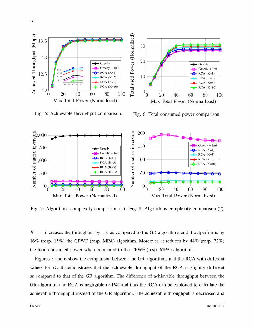
Fig. 5: Achievable throughput comparison.
0 20 40 60 80 1000
10
20
30
Max Total Power (Normailized)
Tota
luse
dP
ow
er(N
orm
ailz
ed)
Greedy
Greedy + Init
RCA (K=1)
RCA (K=3)
RCA (K=5)
RCA (K=10)
Fig. 6: Total consumed power comparison.
0 20 40 60 80 1000
500
1,000
1,500
2,000
Max Total Power (Normalized)
Num
ber
of
mat
rix
inver
sion
Greedy
Greedy + Init
RCA (K=1)
RCA (K=3)
RCA (K=5)
RCA (K=10)
Fig. 7: Algorithms complexity comparison (1).
0 20 40 60 80 1000
50
100
150
200
Max Total Power (Normalized)
Num
ber
of
mat
rix
inver
sion
Greedy + Init
RCA (K=1)
RCA (K=3)
RCA (K=5)
RCA (K=10)
Fig. 8: Algorithms complexity comparison (2).
K = 1 increases the throughput by 1% as compared to the GR algorithms and it outperforms by
16% (resp. 15%) the CPWF (resp. MPA) algorithm. Moreover, it reduces by 44% (resp. 72%)
the total consumed power when compared to the CPWF (resp. MPA) algorithm.
Figures 5 and 6 show the comparison between the GR algorithms and the RCA with different
values for K. It demonstrates that the achievable throughput of the RCA is slightly different
as compared to that of the GR algorithm. The difference of achievable throughput between the
GR algorithm and RCA is negligible (<1%) and thus the RCA can be exploited to calculate the
achievable throughput instead of the GR algorithm. The achievable throughput is decreased and
DRAFT June 10, 2014
19
the total consumed power is increased when K is increased. It means that the use of power is less
efficient when we increase K. In the case of the RCA with K = 10, the achievable throughput
decreases by 0.3% while the computation cost is reduced by 99% (resp. 90%) (see Figure 7)
when compared to the GR algorithm with null initial vector (resp. with initial vector obtained
by CPWF). Note that this algorithm complexity is already strongly reduced as compared with
the standard greedy algorithm that exploits the matrix inversion.
Finally, in Figures 7 and 8, we have plotted the complexity of the different algorithms. Figure
7 shows the complexity comparison between the GR algorithms and the RCA. We can see
that the initialization with CPWF algorithm reduces significantly the complexity of the GR
algorithm. The RCA has reduced the complexity by >90% (resp. 80%) as compared to the GR
algorithm with null initial vector (resp. GR + Init). It is also seen that the complexity of RCA
is decreased when K increases, which can be explained by the diminution of the number of
iterations. Neverthless, the complexity of both cases K = 5 and K = 10 is almost the same. This
is due to the number of failed attempts. Remember that in the reduced complexity algorithm with
K>1, at every iteration, we try to simultaneously increase the number of bits on K subcarriers.
However, at any iteration, if the attempt has failed, we must try to increase those K subcarriers
one by one. This increases the number of matrix inversions.
Time per Number of Total
Algorithm iteration (ms) iteration time (ms)
Standard GR 110 517 56870
GR 28.1 517 14528
GR + Init 14.6 45 657
RCA (K = 1) 2 45 90
RCA (K = 5) 1.9 15 29
RCA (K = 10) 1.75 15 26.25
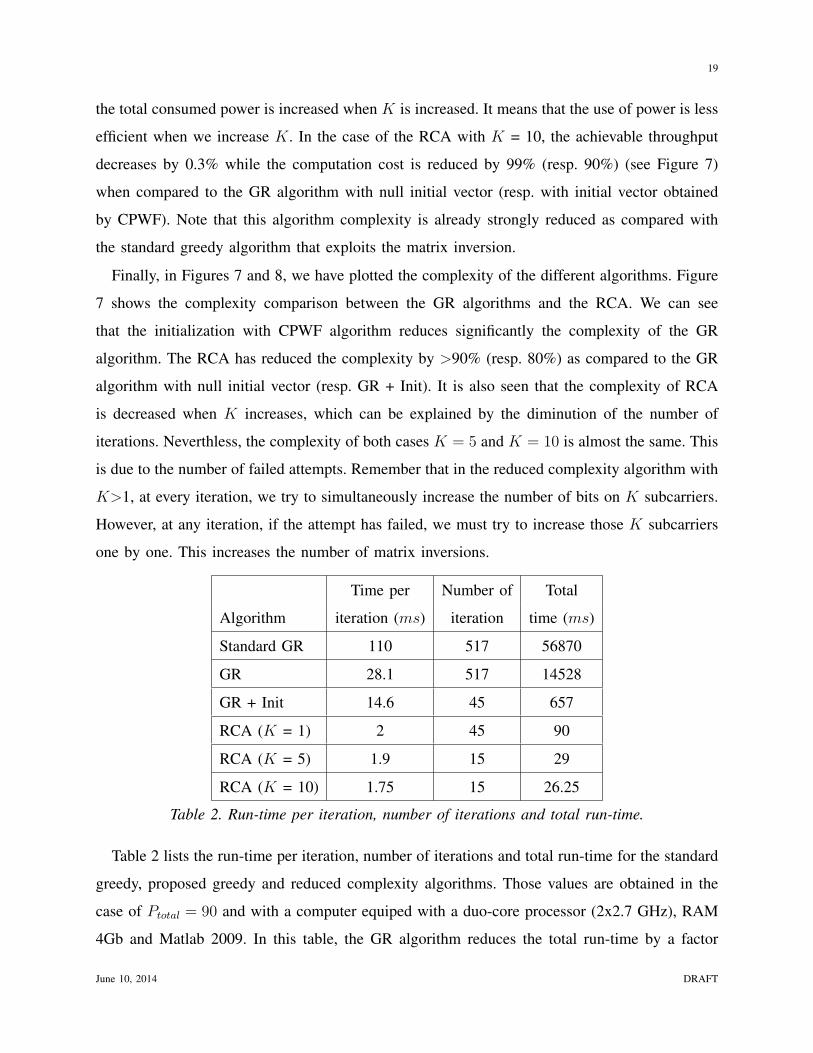
Table 2. Run-time per iteration, number of iterations and total run-time.
Table 2 lists the run-time per iteration, number of iterations and total run-time for the standard
greedy, proposed greedy and reduced complexity algorithms. Those values are obtained in the
case of Ptotal = 90 and with a computer equiped with a duo-core processor (2x2.7 GHz), RAM
4Gb and Matlab 2009. In this table, the GR algorithm reduces the total run-time by a factor
June 10, 2014 DRAFT

20
of 3.8 as compared to the standard greedy algorithm. This gain is almost the same as the run-
time ratio between the direct inversion matrix calculation and the use of iterative calculation to
calculate matrix inversion in Matlab. Indeed, the use of the initial bit-loading vector obtained by
the CPWF algorithm reduces strongly not only the number of iterations but also the run-time
per iteration due to the decrease of the average number of subcarriers for which we have to
calculate the value of cost function. Table 2 also shows that the run-time per iteration of the
reduced complexity algorithm and its number of iterations are much smaller when compared to
the standard and proposed greedy algorithms. Hence, its total run-time is significantly reduced
as compared to the standard and proposed greedy algorithms.
C. Simulation for a realistic PLC system
In this section, the proposed algorithm is applied to a realistic PLC system, where 917
subcarriers are considered (L = 917). The number of channel realizations is set to 200. Figures
9, 10 and 11 show the performance of RCA algorithms with K = 5 and K = 20 when compared
to the CPWF algorithm followed by bit discretization for different classes of channel (class 2, 5
and 9) with a GI of 5.56 µs. In these figures, the throughput obtained with RCA is increased by
17% (resp. 13%) as compared to that of CPWF algorithm for class 2 (resp. class 5) channel. In
these cases, the interference is significant. However, for class 9 channel, the use of the CPWF and
bit discretization is sufficient for an efficient bit-loading and power allocation because there is
almost no interference or the interference power is insignificant as compared to the noise power.
Moreover, in this case, all subcarriers have reached their maximum number of bits determined
by the maximum constellation and the maximum power constraint. Thus, no additional iteration
is required.
Moreover, the performance of RCA for different mandatory GI values from 5.56 µs to 47.12
µs (specified in the IEEE P1901 standard: 5.56, 7.56, 9.56, 11.56, 15.56, 19.56 and 47.12 µs)
is illustrated in Figure 12 with class 2 channel and Ptotal = 500 (normalized). In this figure, the
RCA algorithms improve the achievable throughput by about 10% when compared to the CPWF
+ discretization. Moreover, we can observe that the GI value that maximizes the throughput
coincides with the one that maximizes the capacity. This observation can be used to optimize
jointly the GI value and bit/power allocation. In other words, firstly, we could use the CPWF
algorithm to calculate the capacity for every value of GI specified in the IEEE P1901 standard.
DRAFT June 10, 2014

21
200 400 600 800
80
100
Max Total Power (Normalized)
Ach
ieved
Thro
ughput
(Mbps)
CPWF (continuous)
RCA (K=5)
RCA (K=20)
CPWF (discretized)
Fig. 9: RCA vs CPWF in Class 2 channel.
200 400 600 800
140
150
Max Total Power (Normalized)
Ach
ieved
Thro
ughput
(Mbps)
CPWF (continuous)
RCA (K=5)
RCA (K=20)
CPWF (discretized)
Fig. 10: RCA vs CPWF in Class 5 channel.
200 400 600 800
200
300
400
Max Total Power (Normalized)
Ach
ieved
Thro
ughput
(Mbps)
CPWF (continuous)
RCA (K=5)
RCA (K=20)
CPWF (discretized)
Fig. 11: RCA vs CPWF in Class 9 channel.
10 20 30 40 50
100
150
200
GI length (µs)
Ach
ieved
Thro
ughput
(Mbps)
CPWF (continuous)
RCA (K=5)
RCA (K=20)
CPWF (discretized)
Fig. 12: Throughput with different GI values.
We would choose the GI value corresponding to the maximum capacity. Then, with this GI value,
we use the RCA algorithm to determine the bit-loading and power allocation that maximize the
achievable throughput.
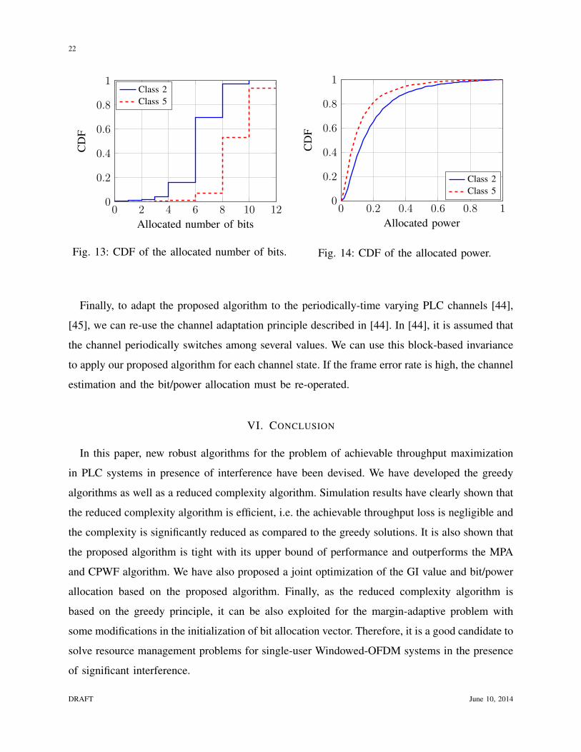
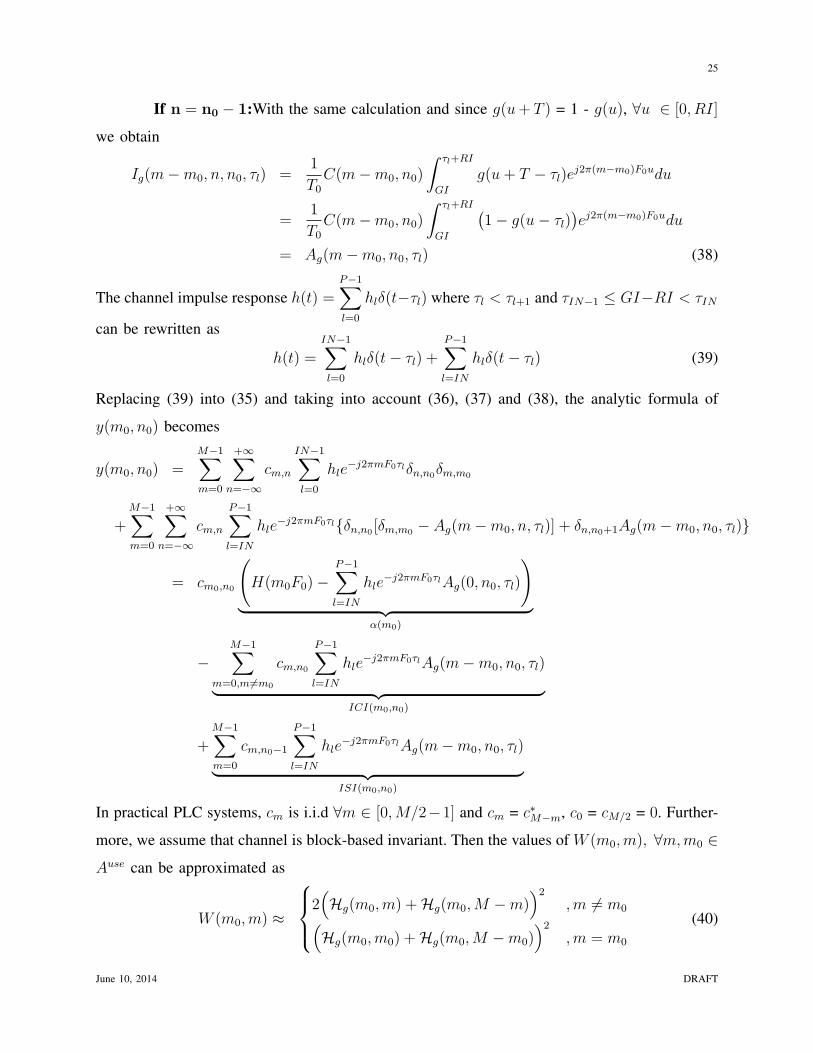
The cumulative distribution function (CDF) of allocated number of bit and of allocated power
for 100 channel realizations are plotted in Figures 13 and 14. We can clearly see that transmitting
on Class 5 channel requires less power than on Class 2 channel (mean value: 0.13 vs 0.2) while
the throughput obtained in Class 5 channel is higher than that of Class 2 channel (mean value:
8.8 vs 6.2 bit).
June 10, 2014 DRAFT
22
0 2 4 6 8 10 120
0.2
0.4
0.6
0.8
1
Allocated number of bits
CD
FClass 2
Class 5
Fig. 13: CDF of the allocated number of bits.
0 0.2 0.4 0.6 0.8 10
0.2
0.4
0.6
0.8
1
Allocated power
CD
F
Class 2
Class 5
Fig. 14: CDF of the allocated power.
Finally, to adapt the proposed algorithm to the periodically-time varying PLC channels [44],
[45], we can re-use the channel adaptation principle described in [44]. In [44], it is assumed that
the channel periodically switches among several values. We can use this block-based invariance
to apply our proposed algorithm for each channel state. If the frame error rate is high, the channel
estimation and the bit/power allocation must be re-operated.
VI. CONCLUSION
In this paper, new robust algorithms for the problem of achievable throughput maximization
in PLC systems in presence of interference have been devised. We have developed the greedy
algorithms as well as a reduced complexity algorithm. Simulation results have clearly shown that
the reduced complexity algorithm is efficient, i.e. the achievable throughput loss is negligible and
the complexity is significantly reduced as compared to the greedy solutions. It is also shown that
the proposed algorithm is tight with its upper bound of performance and outperforms the MPA
and CPWF algorithm. We have also proposed a joint optimization of the GI value and bit/power
allocation based on the proposed algorithm. Finally, as the reduced complexity algorithm is
based on the greedy principle, it can be also exploited for the margin-adaptive problem with
some modifications in the initialization of bit allocation vector. Therefore, it is a good candidate to
solve resource management problems for single-user Windowed-OFDM systems in the presence
of significant interference.
DRAFT June 10, 2014

23
APPENDIX
INTERFERENCE CALCULATION IN PLC SYSTEMS
In this section, we derive ISI and ICI formula in PLC systems. In other words, we carry out
the value of W (a, b), ∀a, b ∈ [1, L]. In this appendix, subcarrier m denotes the m-th available
subcarrier. Under a given spectral mask constraint, only a part of available subcarriers is used.
According to [11], in absence of noise, the demodulated sample on the m0-th subcarrier and
n0-th OFDM symbol is
y(m0, n0) =M−1∑
m=0
+∞∑
n=−∞
cm,n
P−1∑
l=0
hle−j2πmF0τl
1
T0
∫ +∞
−∞
g(t− nT − τl) f(t− n0T )ej2π(m−m0)F0tdt
︸ ︷︷ ︸
Ig(m−m0,n,n0,τl)
(35)
where
• cm,n: Complex QAM, 8-PSK or BPSK symbol located at m-th subcarrier of the n-th OFDM
symbol;
• F0: frequency separation between adjacent carriers;
• T0 =1F0
: FFT window period;
• RI: Roll-off interval of the filter at transmitter (utilized in Windowed-OFDM), in the
conventional OFDM RI = 0;
• GI: Guard interval (GI > RI);
• T = T0 +GI: OFDM symbol period;
• g(t), f(t): filter responses at transmitter (length of T +RI) and receiver (length of T0);
• h(t) =P−1∑
l=0
hlδ(t− τl): Multi-path channel impulse response;
Firstly, the calculation of Ig(m−m0, n, n0, τl) is given according to the value of τl. There are
two cases:
• τl < GI−RI: The filters at the transmitter g(t − nT ) and at the receiver f(t − n0T ) as
well as their relative position are illustrated in Figure 15. In this case, we obtain
Ig(m−m0, n, n0, τl) =1
T0
δn,n0
∫ GI+T0
GI
ej2π(m−m0)F0(u+n0T )du = δn,n0δm,m0 (36)
where we used that T0 = F−10 and δu,v = 1 if u = v and null anywhere else.
June 10, 2014 DRAFT

24
Fig. 15: Relative position of g(t− nT − τl) and f(t− n0T ) in the case of τl < GI −RI .
• GI−RI < τl < T: Figure 16 illustrates the relative position between both filter responses.
By observing Figure 16, we deduce that the term Ig(m − m0, n, n0, τl) is not null if and
only if n = n0 or n = n0 − 1.
Fig. 16: Relative position of g(t− nT − τl) and f(t− n0T ) in the case of τl > GI −RI .
If n = n0:
Ig(m−m0, n, n0, τl) =1
T0
∫ T
GI
g(u− τl) f(u)ej2π(m−m0)F0(u+n0T )du
= ej2π(m−m0)F0n0T︸ ︷︷ ︸
C(m−m0,n0)
1
T0
∫ T
GI
g(u− τl)ej2π(m−m0)F0udu
= C(m−m0, n0)[1
T0
∫ T
GI
ej2π(m−m0)F0udu
+1
T0
∫ τl+RI
GI
(g(u− τl)− 1) ej2π(m−m0)F0udu]
︸ ︷︷ ︸
−G(m−m0,τl)
= C(m−m0, n0)δm,m0 − Ag(m−m0, n0, τl) (37)
where Ag(m−m0, n0, τl) = C(m−m0, n0)G(m−m0, τl).
DRAFT June 10, 2014
25
If n = n0 − 1:With the same calculation and since g(u+ T ) = 1 - g(u), ∀u ∈ [0, RI]
we obtain
Ig(m−m0, n, n0, τl) =1
T0
C(m−m0, n0)
∫ τl+RI
GI
g(u+ T − τl)ej2π(m−m0)F0udu
=1
T0
C(m−m0, n0)
∫ τl+RI
GI
(1− g(u− τl)
)ej2π(m−m0)F0udu
= Ag(m−m0, n0, τl) (38)
The channel impulse response h(t) =P−1∑
l=0
hlδ(t−τl) where τl < τl+1 and τIN−1 ≤ GI−RI < τIN
can be rewritten as
h(t) =IN−1∑
l=0
hlδ(t− τl) +P−1∑
l=IN
hlδ(t− τl) (39)
Replacing (39) into (35) and taking into account (36), (37) and (38), the analytic formula of
y(m0, n0) becomes
y(m0, n0) =M−1∑
m=0
+∞∑
n=−∞
cm,n
IN−1∑
l=0
hle−j2πmF0τlδn,n0δm,m0
+M−1∑
m=0
+∞∑
n=−∞
cm,n
P−1∑
l=IN
hle−j2πmF0τl{δn,n0 [δm,m0 − Ag(m−m0, n, τl)] + δn,n0+1Ag(m−m0, n0, τl)}
= cm0,n0
(
H(m0F0)−P−1∑
l=IN
hle−j2πmF0τlAg(0, n0, τl)
)
︸ ︷︷ ︸
α(m0)
−
M−1∑
m=0,m 6=m0
cm,n0
P−1∑
l=IN
hle−j2πmF0τlAg(m−m0, n0, τl)
︸ ︷︷ ︸
ICI(m0,n0)
+M−1∑
m=0
cm,n0−1
P−1∑
l=IN
hle−j2πmF0τlAg(m−m0, n0, τl)
︸ ︷︷ ︸
ISI(m0,n0)
In practical PLC systems, cm is i.i.d ∀m ∈ [0,M/2−1] and cm = c∗M−m, c0 = cM/2 = 0. Further-
more, we assume that channel is block-based invariant. Then the values of W (m0,m), ∀m,m0 ∈
Ause can be approximated as
W (m0,m) ≈
2(
Hg(m0,m) +Hg(m0,M −m))2
,m 6= m0
(
Hg(m0,m0) +Hg(m0,M −m0))2
,m = m0
(40)
June 10, 2014 DRAFT
26
where H(m0,m) = |
P−1∑
l=IN
hle−j2πmF0τlG(m−m0, τl)|.
Because P (m) = 0, ∀m /∈ Ause, then the interference power on subcarrier m0 ∈ Ause can be
re-written as
PI(m0) =∑
m∈Ause
W (m0,m)P (m) (41)
Finally, the value of W (a, b), ∀a, b ∈ [1, L] is defined as W (a, b) = W (m0,m) where m0 =
Ause(a), m = Ause(b) and W (m0,m) is calculated as in Eq. (40).
REFERENCES
[1] H. Ferreira, L. Lampe, J. Newbury, and T. Swart, Power Line Communication. Wiley, 2010.
[2] H. P. Alliance, HomePlug AV baseline specification., 2007.
[3] A. Cortes, J. Canete, L. Dıez, and M. Torres, “On PLC channel models: an OFDM-based comparison,” IEEE 17th ISPLC,
pp. 333–338, 2013.
[4] H. Latchman, K. Afkhamie, S. Katar, B. Mashburn, R. Newman, and L. Yonge, “High-speed multimedia home networking
over powerline.” NCTA Technical Papers, pp. 9–22, 2005.
[5] M. Russell and L. Stuber, “Bounds on the interchannel interference of OFDM in time-varying impairement.” IEEE
Transactions on Communications, vol. 49(3), pp. 401–404, 2001.
[6] Y. Lang, C. Shixing, and W. Hang, “Effects of cyclic prefix on OFDM systems over time-varying channels.” IEEE 16th
PIMRC, vol. 2, pp. 750–753, 2005.
[7] L. Wan, C. Huang, and C. Shen, “An ISI suppression technique using time-domain windowing for OFDM systems.” IEEE
VTC 2006, vol. 5, pp. 2518–2522, 2006.
[8] J. Martinez, E. Naya, T. Entrambasaguas, and M. Abril, “Low complexity synchronization and frequency equalization for
OFDM systems.” 14th ICECS, pp. 987–990, 2007.
[9] S. Chen and C. Zhu, “ISI and ICI analysis and mitigation for OFDM systems with insufficient cyclic prefix in time-varying
channels.” IEEE Transactions on Consumer Electronics, vol. 50(1), pp. 78–83, 2004.
[10] I. C. Society, IEEE Standard for Broadband over Power Line Networks: Medium Access Control and Physical Layer
Specication., 2010.
[11] P. Achaichia, M. L. Bot, and P. Siohan, “OFDM/OQAM: A solution to efficiently increase the capacity of future PLC
networks.” IEEE Transactions on Power Delivery, vol. 26(4), pp. 2443–2455, 2011.
[12] L. Dinh, Q. Yin, K. Deng, and Y. Meng, “A practical computationally efficient power and bit allocation for wireless OFDM
systems.” IEEE ICC ’06, vol. 12, pp. 5628–5633, 2006.
[13] E. Guerrini, G. D. Amico, P. Bisaglia, and L. Guerrini, “Bit-loading algorithms and SNR estimate for HomePlug AV.”
IEEE ISPLC 2007, pp. 77–82, 2007.
[14] C. Y. Wong, R. Cheng, K. Letaief, and R. Murch, “Multicarrier OFDM with adaptive subcarrier, bit, and power allocation.”
IEEE Journal on Selected Areas in Communication, vol. 17(10), pp. 1747–1758, 1999.
[15] L. Goldfeld, V. Lyandres, and D. Wulicj, “Minimum BER power loading for OFDM in fading channel.” IEEE Transactions
on Communications, vol. 50(11), pp. 1729–1733, 2002.
[16] W. Yu, W. Rheem, S. Boyd, and J. M. Cioffi, “Iterative water-filling for gaussian vector multiple access channel.” IEEE
Transactions on Information Theory, vol. 50(1), pp. 145–152, 2004.
[17] S. D’Alessandro, A. M. Tonello, and L. Lampe, “On Power Allocation in Adaptive Cyclic Prefix OFDM.” IEEE ISPLC,
pp. 183–188, 2010.
[18] M. Tonello, S. Alessandro, and L. Lampe, “Cyclic prefix design and allocation in bit-loaded OFDM over plc channels.”
IEEE Transactions on Communications, vol. 58(11), pp. 3265–3276, 2010.
[19] M. Wolkerstorfer, P. Tsiaflakis, M. Moonen, and D. Statovci, “Joint power-loading and cyclic prefix length optimization
for OFDM-based communication.” IEEE ICASSP 2013, 2013.
[20] W. Yu, G. Ginis, and J. M. Cioffi, “Distributed Multiuser Power Control for Digital Subscriber Lines.” IEEE Journal on
Selected Areas in Communications, vol. 20(5), p. 11051115, 2002.
DRAFT June 10, 2014

27
[21] S. T. Chung, S. J. Kim, J. Lee, and J. M. Cioffi, “A Game-Theoretic Approach to Power Allocation in Frequency-Selective
Gaussian Interference Channels.” IEEE Int. Sym. on Inf. Theory 2003, 2003.
[22] D. Alessandro, M. Tonello, and L. Lampe, “Adaptive pulse-shaped OFDM with application to in-home power line
communication,” Telecommunication systems, vol. 51(1), pp. 3–13, 2012.
[23] Y. Huang and B. Rao, “On using a priori channel statistics for cyclic prefix optimization in OFDM.” IEEE Wireless
Communications and Networking Conference 2011, pp. 1460–1465, 2011.
[24] ——, “Awareness of channel statistics for slow cyclic prefix adaptation in an OFDMA system.” IEEE Wireless
Communications Letters, vol. 1(4), pp. 332–335, 2012.
[25] M. K. Chan and W. Yu, “Multiuser spectrum optimization for discrete multitone systems with asynchronous crosstalk,”
IEEE Transactions on Signal Processing, vol. 55(11), pp. 5425–5435, 2007.
[26] J. Seoane, S. Wilson, and S. Gelfand, “Analysis of intertone and interblock interference in OFDM when the length of the
cyclic prefix is shorter than the length of the impulse response of the channel,” IEEE GLOBECOM 1995, pp. 2069–2074,
1995.
[27] J. M. Cioffi, A multicarrier prime. [Online]. Available: http://www.stanford.edu/group/cioffi/publications.html
[28] T. H. Cormen, C. E. Leiserson, R. L. Rivest, and C. Stein, Introduction to Algorithms - 3rd edition. MIT, 2009.
[29] J. M. Cioffi, Advanced Digital communication. [Online]. Available: http://www.stanford.edu/class/ee379c/readerfiles/
chap4.pdf
[30] W. Al-Hanafy and S. Weiss, “A new low-cost discrete bit loading using greedy power allocation,” Mosharaka International
Conference on Communications, Computers and Applications, 2009.
[31] J.-H. Wen, C.-H. Chiang, T.-J. Hsu, and H.-L. Hung, “Resource management techniques for OFDM systems with the
presence of ici,” Wireless Personal Communication, vol. 65(3), pp. 515–535, 2011.
[32] E. Guerrini, L. Guerrieri, D. Veronesi, P. Bisaglia, and R. Cappelletti, “LLR-based bit-loading algorithm and its applications
to HomePlug AV over OPERA power-line channels with impulsive noise,” IEEE Journal of Communications, vol. 4(7),
pp. 454–462, 2009.
[33] R. Cendrillon, W. Yu, M. Moonen, J. Verlinden, and T. Bostoen, “Optimal multiuser spectrum management for digital
subscriber lines,” IEEE Transactions on Communications, vol. 54(5), pp. 922–933, 2007.
[34] W. Yu and R. Lui, “Dual methods for nonconvex spectrum optimization os multi-carriers systems,” IEEE Transactions on
Communications, vol. 54(6), pp. 1310–1322, 2007.
[35] R. Cendrillon and M. Moonen, “Iterative spectrum balancing for digital subscriber lines,” IEEE ICC, vol. 3, pp. 1937–1941,
2005.
[36] Y. Xu, T. Le-Ngoc, and S. Panigrahi, “Global concave minimization for optimal spectrum balancing in multiuser DSL
networks,” IEEE Transactions on Signal Processing, vol. 56(7), pp. 2875–2885, 2008.
[37] L. Qian, Y. Zhang, and J. Huang, “Mapel: Achieving global optimality for non-convex wireless power control problem,”
IEEE Transactions on Wireless Communications, vol. 8(3), pp. 1526–1563, 2009.
[38] N. Papandreou and T. Antonakopoulos, “A new computationally efficient discrete bit-loading algorithm for DMT
applications,” IEEE Transactions on Communications, vol. 53(5), pp. 785–789, 2006.
[39] C. M. Akujuobi, J. Shen, and M. N. O. Sadiku, “A new parallel greedy bit-loading algorithm with fairness for multiple
users in a DMT system.” IEEE Transactions on Communications, vol. 54, pp. 1374–1380, 2006.
[40] M. Tonello, F. Versolatto, B. Bejar, and S. Zazo, “A fitting algorithm for random modeling the PLC channel.” IEEE
Transactions on Power Delivery, vol. 27(3), pp. 1477–1484, 2012.
[41] Seventh Framework Programme: Theme 3 ICT-213311 OMEGA, Deliverable D3.2, “PLC Channel Characterization and
Modelling,” Information and Communication Technologies (ICT), Tech. Rep., 2011, v1.2.
[42] R. Hashmat, P. Pagani, and T. Chonavel, “Analysis and modeling of background noise for inhome MIMO-PLC channels.”
IEEE ISPLC 2012, pp. 316–321, 2012.
[43] H. Steendam and M. Moeneclaey, “Analysis and optimization of the performance of OFDM on frequency-selective time-
selective fading channels.” IEEE Transactions on Communications, vol. 47(12), pp. 1811–1819, 1999.
[44] K.-H. Kim, H.-B. Lee, Y.-H. Kim, and S.-C. Kim, “Channel Adaptation for Time-varying Powerline Channel and Noise
Synchronized with AC Cycle.” IEEE ISPLC 2009, pp. 250–254, 2009.
[45] M. Picorone, R. Amado, and V. Ribeiro, “Linear and Periodically Time-Varying PLC Channels Estimation in the Presence
of Impulsive Noise.” IEEE ISPLC 2010, pp. 255–260.
June 10, 2014 DRAFT