acd5ini - aeqbroadcast.comaeqbroadcast.com/man/acd5001.pdf · g.722 h.221/h.242, 64kbps, 7khz audio...
TRANSCRIPT

A.E.Q., S.A. the manufacturer of this equipment, is “RegisteredCompany” number ER-080/1/96 conforming to the AENOR UNE EN - ISO - 9001 qualityassurance standard.
ACD-5001Dual Channel Multiformat
Digital Audiocodec with Intercom
Audiocodificador Digital Doble CanalMultinorma con Intercomunicación
USER’S MANUAL / MANUAL DE USUARIOED. 10/00

ACD-5001Dual Channel Multiformat Digital Audiocodec with Intercom 2
ATTENTION
- Consult the ‘TECHNICAL SUPPORT’ link in our web page www.aeq.es fordownloading new software upgrade versions in the future.
- Consult the ‘Readme.txt’ file in the diskette included in this package to obtainuser’s manual upgrading notes.

ACD-5001Dual Channel Multiformat Digital Audiocodec with Intercom 3
INDEX
1. DESCRIPTION OF THE EQUIPMENT1.1. BASIC DESIGN CONCEPTS1.2. SPECIFICATIONS
2. POWER SUPPLY2.1. GENERAL
2.1.1. UNIT POWER SUPPLY2.1.2. SWITCHING ON
3. INSTALLATION AND WIRING3.1. DESCRIPTION OF THE FRONT PANEL
3.2. DESCRIPTION OF THE REAR PANEL 4. DESCRIPTION OF CONTROLS
4.1. CONTROL PANEL4.2. VISUALISATION AND USER INTERFACE CONTROL SECTION4.3. DIALLING AND CHANNEL SELECTION SECTION4.4. INTERCOMMUNICATION SECTION4.5. MANUAL/AUTOMATIC CALL ANSWERING SECTION4.6. MONITORING SECTION
5. USER INTERFACE5.1. AUTOMATIC START-UP MODE5.2. MANUAL START-UP MODE5.2.1. ACCESS TO THE ‘PHONE BOOK
5.2.2. ACCESS TO RECALL5.2.3. ACCESS TO CODIFICATION CHANGING5.2.4. ACCESS TO START-UP CONFIGURATIONS5.2.5. MANUAL DIALLING5.2.6. CALL GENERATION5.2.7. CONNECTION ESTABLISHED
5.2.7.1. DATA CHANNEL5.2.7.2. VUMETER MODE
5.2.8. RECEIVING CALLS 5.3. GENERATION OF DTMF TONES FOR REMOTE CONTROL
6. UPGRADING THE INTERNAL SOFTWARE (FIRMWARE UPGRADE)6.1. SYSTEM DESCRIPTION6.2. REQUIREMENTS OF THE PC USED FOR UPGRADING6.3. CONNECTIONS FOR CONTROL COMPUTER6.4. FIRMWARE UPGRADING
7. TECHNICAL SPECIFICATIONS
APPENDIX I: GUIDE TO RAPID USE
APPENDIX 2: COMPATIBILITY WITH TELOS AND CCS AUDIOCODECS.
APPENDIX 3: AEQ WARRANTY

ACD-5001Dual Channel Multiformat Digital Audiocodec with Intercom 4
1. DESCRIPTION OF THE EQUIPMENT
1.1. Basic design concepts
The AEQ ACD-5001 is a multiformat dual audio encoder/decoder for ISDN lines, which offersall tools necessary to establish communications through either two independent bi-directionalmono audio circuits, or one stereo or one 20kHz mono circuit, between two remote points, andgiving the best possible sound quality and ease of use in a single unit. It is possible to enable a1200-baud transparent point to point bi-directional data channel alongside the audio channel.It is equipped with a full-duplex Intercommunicator, which permits communication with the twoaudio channels individually and simply, without external operations or cabling.The monitoring functions, also available on the front panel, makes it possible to listen to all thesignals generated or received by the equipment without affecting the studio audio.In short, for its high performance, ease of use and competitive price, the AEQ ACD-5001 isunique in the digital communications market.
Using the Automatic Start-Up System, it is possible to completely program the mode the unitwill adopt on start-up. In this way, the technician can define all the communication parameters,including telephone numbers, and the commentator only has to select the switch on the rearpanel that corresponds to the required configuration. When connecting the power supplyautomatically generates calls to the pre-set numbers.
1.2. Specifications:
• Dual Channel Multiformat Digital Audiocodec for ISDN lines with Intercom.• Independent dialling for each channel B, when using ISDN, with extension number capacity
(where this is available).• In 64 Kbps modes, it is possible to make the codification algorithm of each channel B
independent.• Display screen (2 lines X 24 characters). Indication of state, numbers dialled, telephone
book and menu options.• Channel Selection of Automatic or Manual Call Answering.• On screen call status display (in progress, connected, communicating, busy, call rejected
etc.)• Access to the Intercommunication circuit, with automatic disconnection of the studio audio.• Intercommunicator microphone input and headphone output mounted on the front panel,
with independent controls for each channel.• Alphanumeric telephone book with 255 entries. Audio encoding mode configuration and
edition can be performed simply and intuitively using the equipment’s integrated keyboard.• Line output, with selection for return, send or both, for each audio channel.• Line input for each audio channel.• DTMF tone generation, to control remote equipment.• Internal EPROM Flash memory that allows future software upgrades without the necessity
of opening the unit.• Up to 30 different microswitch selectable configurations may be defined and stored, which
can be automatically activated when the equipment is switched-on.• Available code algorithms:
G.711, 64Kbps, 3.5kHz audioG.722 Statistical, 64Kbps, 7kHz audioG.722 H.221/H.242, 64Kbps, 7kHz audioLD-Extend, 15 kHz mono audio with low delay /128 KbpsISO/MPEG LII mono 24 kHz, 64Kbps, 11kHz audioISO/MPEG LII mono 32 kHz, 64Kbps, 10.5kHz audioISO/MPEG LII mono 48 kHz, multiplexing J.52/IMUX, 128 Kbps, 20kHz audioISO/MPEG LII Joint Stereo 48kHz, multiplexing J.52/IMUX, 128Kbps, 15kHz audio stereoISO/MPEG LII Dual 32 kHz, multiplexing J.52/IMUX, 128Kbps, 10.5kHz audio dual

ACD-5001Dual Channel Multiformat Digital Audiocodec with Intercom 5
2. POWER SUPPLY
2.1. General The power supply connector (1) is found on the rear panel of the unit.
2.1.1. Unit power supply Power is supplied to the equipment through the connector marked DC-INPUT using the cabledelivered with the unit. The equipment accepts AC supplies of 110V or 220V. The voltageselector is found inside the fuse case: the fuse must be taken out of the unit and the case mustbe turned on 90º, so the new voltage selection may be seen from outside the case. Powerconsumption is of approx. 30VA. 2.1.2. Switching on
Before connecting the power supply ensure the on/off switch is in the OFF position.Once the lockable plug is correctly connected to the unit, it should be connected to the networksupply. Turn the power supply switch to ON. If all the previous steps have been correctly followed, thedisplay will illuminate, indicating that the equipment is receiving power.
1

ACD-5001Dual Channel Multiformat Digital Audiocodec with Intercom 6
3. INSTALLATION AND WIRING
To clarify the installation and wiring process it is necessary to be familiar with the connectorsand configurable elements (on the front and rear panels). It must be remembered that thisequipment may be connected to either ISDN or CTN lines and the wiring is different in eachcase. 3.1 Description of the front panel
The following controls are mounted on the front and Control panels; these are explained later:
(1) The LCD display(2) The numeric keyboard(3) The Multifunction and Audiocodec Control Keys(4) XLR3 connector for the connection of an intercommunication microphone(5) Headphone output for monitoring signals received and sent(6) Power supply switch (ON)
Intercommunication Microphone Input
The microphones are normally supplied with the appropriate connectors for direct connection tothe Audiocodec. The connector wiring is shown below:
XLR connectors
1: ground2: microphone V+3: microphone V-
Headphone Output A standard TRS ¼” headphone output jack is fitted. The connector wiring is shown below:
¼” Jack connectors Tip: Left earpiece Ring: Right earpiece Sleeve: Common ground
4
1
3
2
3
5
6
ACD-5001Dual Channel Multiformat Digital Audiocodec with Intercom 7
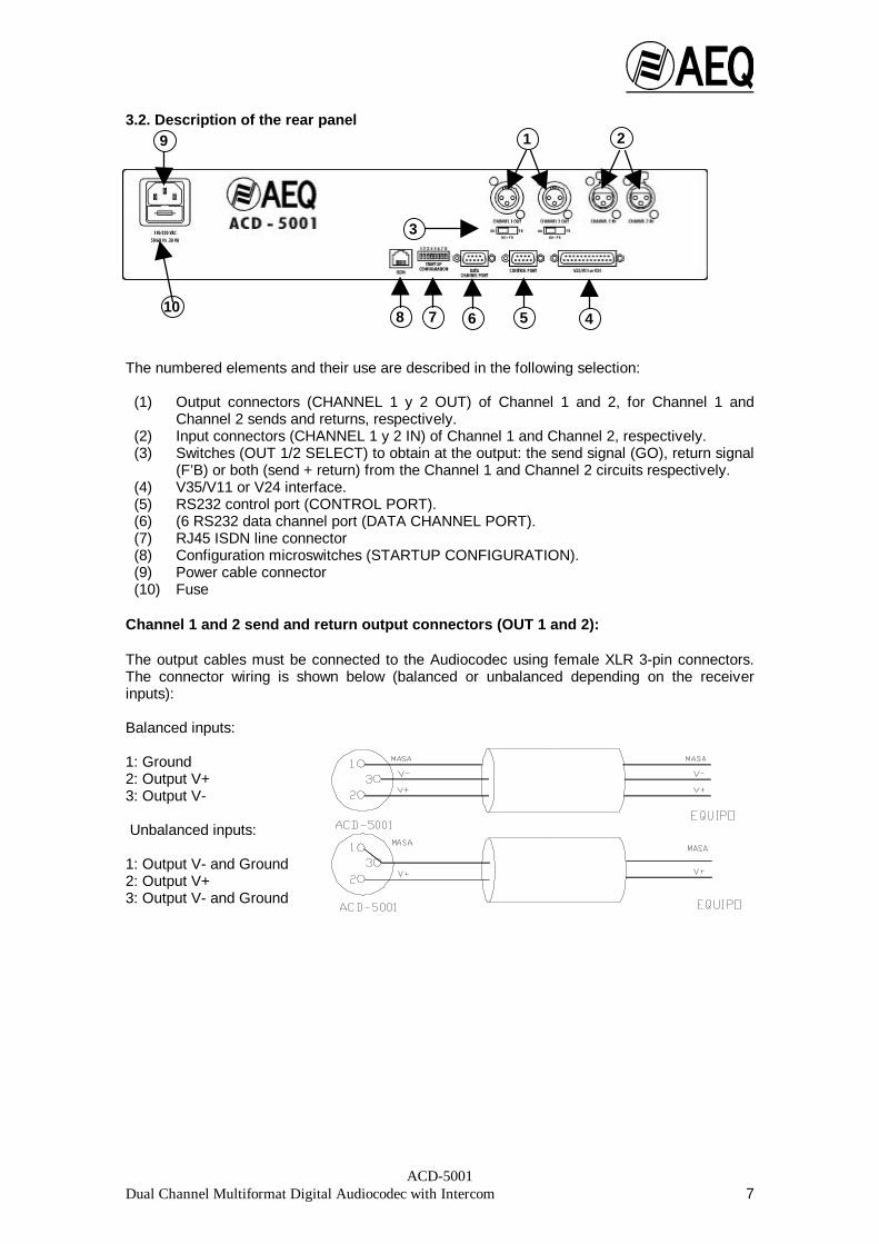
3.2. Description of the rear panel The numbered elements and their use are described in the following selection:
(1) Output connectors (CHANNEL 1 y 2 OUT) of Channel 1 and 2, for Channel 1 andChannel 2 sends and returns, respectively.
(2) Input connectors (CHANNEL 1 y 2 IN) of Channel 1 and Channel 2, respectively.(3) Switches (OUT 1/2 SELECT) to obtain at the output: the send signal (GO), return signal
(F’B) or both (send + return) from the Channel 1 and Channel 2 circuits respectively.(4) V35/V11 or V24 interface.(5) RS232 control port (CONTROL PORT).(6) (6 RS232 data channel port (DATA CHANNEL PORT).(7) RJ45 ISDN line connector(8) Configuration microswitches (STARTUP CONFIGURATION).(9) Power cable connector(10) Fuse
Channel 1 and 2 send and return output connectors (OUT 1 and 2): The output cables must be connected to the Audiocodec using female XLR 3-pin connectors.The connector wiring is shown below (balanced or unbalanced depending on the receiverinputs): Balanced inputs: 1: Ground 2: Output V+ 3: Output V- Unbalanced inputs: 1: Output V- and Ground 2: Output V+ 3: Output V- and Ground
4
1 2
3
5678
9
10

ACD-5001Dual Channel Multiformat Digital Audiocodec with Intercom 8
Input connectors 1 (CHANNEL 1 IN) and 2 (CHANNEL 2 IN). The input cables must be connected to the Audiocodec using male XLR 3-pin connectors. Theconnector wiring is shown below (balanced or unbalanced depending on the receiver inputs): Balanced Outputs: 1: Ground 2: Input V+ 3: Input V- Unbalanced Outputs: 1: Input V- and Ground 2: Input V+ 3: Input V- and Ground V35/V11 or V24 Interface:
DB25 connector:
Admits 2 types of external TA:V35 interface (V11): Uses unbalanced asynchronous control signals, while synchronous clockand data signals are balanced.V24 interface: This is a synchronous RS232. The active contacts are:
V35/V11 PINClock (RCX) V+ 13Clock (RCX) V- 14TX V+ 11TX V- 10RX V+ 21RX V- 19Common (V35/V11 – V24) PINDTR (Data Terminal Ready) 20CD (Carrier Detect) 8GND 7 CTS (Clear to send) 5 RTS (Request to send) 4 V24 PIN TX 2 RX 3 Clock (RXC) 17

ACD-5001Dual Channel Multiformat Digital Audiocodec with Intercom 9
Connections for Control (CONTROL PORT) and Data (DATA CHANNEL PORT) (RS232ports)
The unit has two female DB 9 chassis mounted connectors for configuration and transmissionof auxiliary data in conjunction with an external computer communicating through RS 232protocol (a cable fitted with male connectors must therefore be used). The active contacts are:
TX 2 RX 3 GND 5
A Pin-to-Pin Male-Female cable must be used and connected to the PC serial port. For details of the PC serial communication port, consult the user manual supplied with thecomputer. RJ45 chassis connector wiring
The RJ 45 connector connects the terminal adapter, which isincluded in the equipment, with the ISDN access point (Networkterminal). This connector wiring is standard according to the followingdiagram.
For connection to the ISDN line socket the cable supplied with the equipment, or
similar, must be used.
Cable Number Connections 1 2 3 ---------- Tx V+ 4 ---------- Rx V- 5 ---------- Rx V+ 6 ---------- Tx V- 7 8
DIP Microswitches
Eight DIP microswitches, numbered 1 to 8, are incorporated in the unit. These are accessedfrom the rear panel. Each microswitch functions as follows:
Microswitch Function1 None2 Multiplexing (J.52/IMUX) 128Kbps modes3 None
4 - 8 Automatic start-up configurations All changes to the microswitch positions to modify the start-up configuration must be madebefore starting the unit (with the unit switched-off). Alterations made to the microswitchpositions once the unit is in operation will have no effect and will not change the currentconfiguration.• The selection of multiplex mode for the 128 Kbps channels is performed using microswitch
2: the up position selects IMUX; the down position selects J.52. See also Appendix 2.• Automatic start-up function configurations: Allow the unit to start-up using predetermined
pre-programmed parameters (code, numbers to dial, etc.). The unit has two pre-programmed software configurations available (configuration C00 – Test mode, andconfiguration C01 – Manual Start-up mode), these cannot be modified. The remaining 30configurations (C002 – C031) are freely available to the user.Important: Check that your AEQ ACD-5001 is not set in Test mode.
FRONT VIEW

ACD-5001Dual Channel Multiformat Digital Audiocodec with Intercom 10
Configuration of microswitches 4 - 8 for access to the automatic start-up configurations: Conf. 4 5 6 7 8
C00 * 0 0 0 0 0 C01 * 0 0 0 0 1 C02 0 0 0 1 0 C03 0 0 0 1 1 C04 0 0 1 0 0 C05 0 0 1 0 1 C06 0 0 1 1 0 C07 0 0 1 1 1 C08 0 1 0 0 0 C09 0 1 0 0 1 C10 0 1 0 1 0 C11 0 1 0 1 1 C12 0 1 1 0 0 C13 0 1 1 0 1 C14 0 1 1 1 0 C15 0 1 1 1 1
Conf. 4 5 6 7 8 C16 1 0 0 0 0 C17 1 0 0 0 1 C18 1 0 0 1 0 C19 1 0 0 1 1 C20 1 0 1 0 0 C21 1 0 1 0 1 C22 1 0 1 1 0 C23 1 0 1 1 1 C24 1 1 0 0 0 C25 1 1 0 0 1 C26 1 1 0 1 0 C27 1 1 0 1 1 C28 1 1 1 0 0 C29 1 1 1 0 1 C30 1 1 1 1 0 C31 1 1 1 1 1
(1 = ON, microswitch in the ‘up’ position; 0 = OFF, microswitch in the ‘down’ position) * Pre-set configurations, these cannot be modified by the user. Power supply: Power is delivered to the Audiocodec through the AC-INPUT connector with the supplied cableconnected to an appropriate AC-socket that provides the right voltage (110 or 220VAC). Fuses: Two types, depending on the power supply voltage to be used: - for 110VAC the fuse must be 0.4A, Slow blow.- for 220VAC the fuse must be 0.4A, Slow blow.

ACD-5001Dual Channel Multiformat Digital Audiocodec with Intercom 11
4. DESCRIPTION OF CONTROLS 4.1. Control Panel From the operational point of view, the control panel is divided into five sections:
• Visualisation and User Interface Control Section
• Dialling and Channel Selection Section
• Intercommunication section
• Manual/Automatic call answering section
• Monitoring section
4.2. Visualisation and User Interface Control Section The status of the AEQ ACD-5001 Audiocodec (connection, codification, number dialled, etc.),as well as the configuration, can be visualised on the Display (2 lines X 24 characters). Accessis gained to the various configuration menus, dialling, telephone book, etc. by using the fourpushbuttons (Multifunction Keys) situated under the visual Display.
The upper line of the Display is foruser information and the lower lineshows the function associated witheach of the four Multifunction keys.The use of the Multifunction keys isexplained in section 5 “UserInterface”.
Fig. 4.1 Position of the control panel elements.

ACD-5001Dual Channel Multiformat Digital Audiocodec with Intercom 12
4.3. Dialling and Channel Selection Section Disconnection of the Audiocodec from the various circuits (Program/ Co-ordination), as well asthe selection of the channel to dial and generation of DTMF Tones for remote control and otheruses, is executed from the Dialler and Channel Selection Section.
• NUMERIC KEYBOARD. This is forentering the correspondent’s number.
• DISCONNECT CHANN 1. Pressingthis button will disconnect theestablished Channel 1 output line
• DISCONNECT CHANN 2. Pressingthis button will disconnect theestablished Channel 2 output line. If the connection is in 128 mode,pressing either of the two switcheswill effect disconnection.
• SELECT CHAN1/CHAN2. Pressingthis button selects the desired outputcircuit (Channel 1/Channel 2) formaking the connection, dialling orDTMF tone generation. The currentselection is shown in the upper rightcorner of the Display..
• HOLD FOR DTMF GEN. DTMF tones for remote control and other functions can begenerated by keeping this button pressed and using the numeric keyboard. The tones arethen sent via the selected output (Program/Co-ordination) using the SELECTPROG/COORD CHANNEL key. (The audio signal in the corresponding output channel ismuted during tone keying/generation).
4.4. Intercommunication Section
The AEQ ACD-5001 Audiocodec possesses an Intercommunication system that allows thetechnician to use one of the two channels (or both at the same time) to communicate with theremote post through a microphone that must be connected to the appropriate connectorsituated on the front panel.
The Intercommunicator is operated bysimply pressing the button corresponding tothe channel required. The button is locatedunder a protective tab to prevent accidentalmicrophone connection (the use of theIntercommunication microphone mutes theaudio in the channel used). The corresponding LED and the “ACTIVE”indicator light when one of the two buttons ispressed to indicate that theintercommunicator is active and whichchannel is being used. Channels 1, 2, or bothtogether, can be used forIntercommunication.
Intercommunication, whether through one or two channels, is terminated by pressing the"RESET" button. The LEDs associated with the channels will be extinguished together with the“ACTIVE” indicator.
ACD-5001Dual Channel Multiformat Digital Audiocodec with Intercom 13
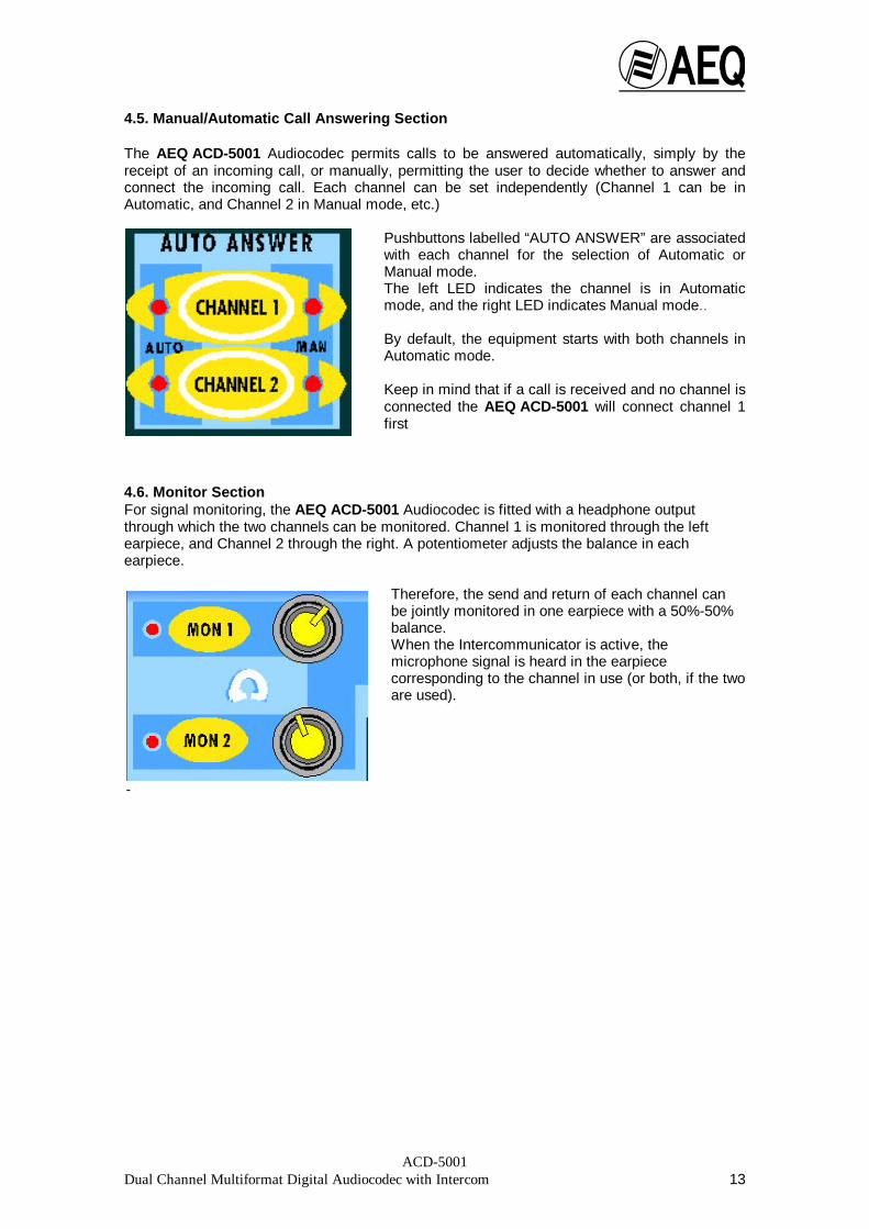
4.5. Manual/Automatic Call Answering Section The AEQ ACD-5001 Audiocodec permits calls to be answered automatically, simply by thereceipt of an incoming call, or manually, permitting the user to decide whether to answer andconnect the incoming call. Each channel can be set independently (Channel 1 can be inAutomatic, and Channel 2 in Manual mode, etc.)
Pushbuttons labelled “AUTO ANSWER” are associatedwith each channel for the selection of Automatic orManual mode. The left LED indicates the channel is in Automaticmode, and the right LED indicates Manual mode.. By default, the equipment starts with both channels inAutomatic mode. Keep in mind that if a call is received and no channel isconnected the AEQ ACD-5001 will connect channel 1first
4.6. Monitor Section For signal monitoring, the AEQ ACD-5001 Audiocodec is fitted with a headphone outputthrough which the two channels can be monitored. Channel 1 is monitored through the leftearpiece, and Channel 2 through the right. A potentiometer adjusts the balance in eachearpiece.
Therefore, the send and return of each channel canbe jointly monitored in one earpiece with a 50%-50%balance. When the Intercommunicator is active, themicrophone signal is heard in the earpiececorresponding to the channel in use (or both, if the twoare used).
-

ACD-5001Dual Channel Multiformat Digital Audiocodec with Intercom 14
5. USER INTERFACE Start-up: 5.1. 5.1. Automatic Start-up Mode:
There are 30 possible automatic start-up configurations that are selectable through 5 DIPswitches on the back of the unit. Positions C02 to C31 may be user configured. For theimplementation of automatic start-up configurations see section 3.2 “DIP Microswitches”.
Position C00 .................... Test mode, used under Technical Service instructionsPosition C01 .................... Manual start-up mode (see section 5.2)
Positions C02 to C31 .. .... User defined modes The following window appears when the equipment is started with the DIP SWITCHES in anyposition between C02 and C31:
Two seconds later, an informative window appears showing the loaded versions of differentmodules (Micro, DSP, and TA’s) of AEQ AEQ-5001.
Two seconds later, a window appears in which the configuration number is indicated, in thisexample number 2 (C02):
Following this, a call is automatically generated to the number selected for the Channel 1 usingthe selected codification mode. Once the call is established, or a corresponding releasemessage is seen, the unit automatically generates the call for the Channel 2 circuit.
Once the connection is established with the remote terminal, the connection establishedwindows appear. If the configuration chosen for the automatic start-up is free the following window will appear:
indicating that there are no numbers to dial. One second later the unit automatically passes to the manual start-up mode stand-by window(initial window). Finally if the automatically established communications are freed using the “CHANN 1DISCONNECT” and/or “CHANN 2 DISCONNECT” keys, the unit will pass to the manualstart-up mode stand-by window.
ACD-5001 POWERED BY AEQ ISDN AUDIOCODEC
CONFIGURATION NUMBER 2 AUTOMATIC MODE STARTUP
STARTUP CONFIGURATION SELECTED IS FREE
MCUV1.10 DSPV1.06 TA1V1.04 TA1V1.04 PAUSE
ACD-5001Dual Channel Multiformat Digital Audiocodec with Intercom 15
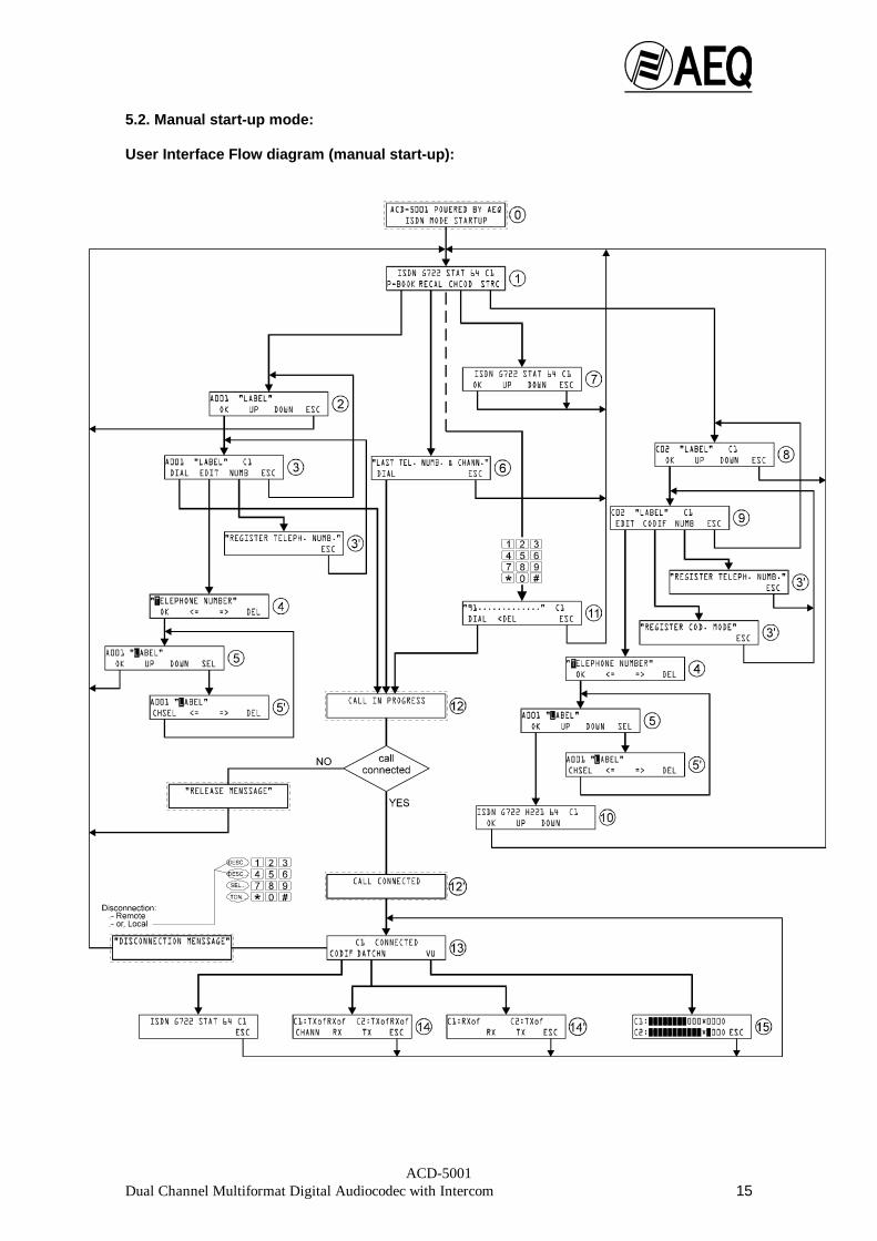
5.2. Manual start-up mode: User Interface Flow diagram (manual start-up):
ACD-5001Dual Channel Multiformat Digital Audiocodec with Intercom 16
This start-up mode is selected when the Start-up Configuration DIP switches are in positionC01.
The following window appears on starting the unit:
Two seconds later the stand-by or manual mode initial window appears:
In the initial window (1), the default codification mode selected for the establishment of theChannel 1 circuit connection appears on the top line of the display. The key “SELECT CHAN1/CHAN 2” is used to change to the circuit desired for the connection. The message “ISDNG722 STAT 64 C2” will appear on the top line, indicating that the codification mode is activeand that the Channel 2 circuit has been selected. The function associated with each of the multifunction keys appears on the bottom line of thedisplay.. “P-BOOK” “RECAL” “CHCOD” “STRC” In this situation the user can perform five operations:
1.- Activating “P-BOOK” (Telephone Book) displays the ‘phone book which is includedin the unit.2.- Activating “RECAL” (RECALL) displays the number and circuit used in the lastconnection.3.- Activating “CHCOD” (CHANGE CODIFICATION) accesses the window which allowsthe mode of connection codification to be changed.4.- Activating “STRC” (SAVE CONFIGURATION) accesses the window which allows anew or existing modified start-up configuration to be saved. 5.- Finally, if the numerical keyboard is used in the stand-by state, the manual numbercomposition window appears and the user can manually enter a telephone number andmake a call.
The following describes the use of the above functions: 5.2.1. Access to the ‘phone book
On activating “P-BOOK” the following window appears:
The first entry stored in the ‘phone book’s non-volatile RAM memory appears on the upper lineof the display.
Fig. 1
(2)
ACD-5001 POWERED BY AEQ ISDN MODE STARTUP
ISDN G722 STAT 64 C1 P-BOOK RECAL CHCOD STRC
Fig. 0
A001 LABEL OK UP DOWN ESC
ACD-5001Dual Channel Multiformat Digital Audiocodec with Intercom 17
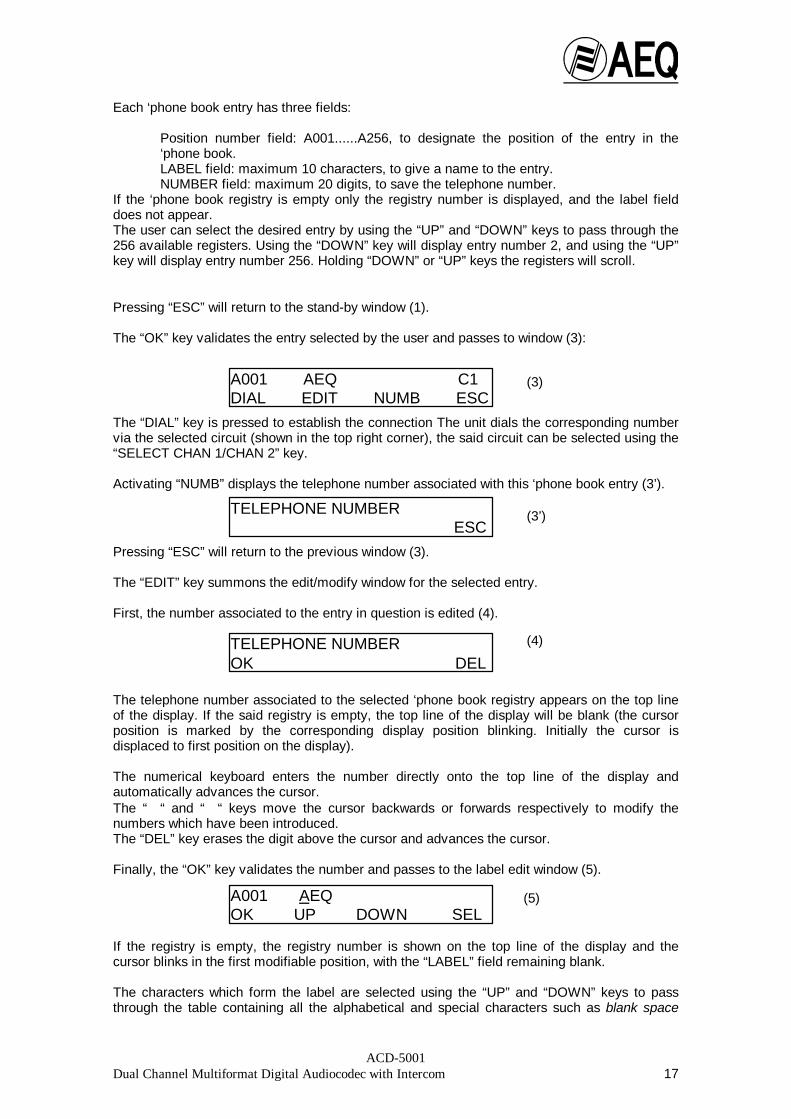
Each ‘phone book entry has three fields:
Position number field: A001......A256, to designate the position of the entry in the‘phone book.LABEL field: maximum 10 characters, to give a name to the entry. NUMBER field: maximum 20 digits, to save the telephone number.
If the ‘phone book registry is empty only the registry number is displayed, and the label fielddoes not appear. The user can select the desired entry by using the “UP” and “DOWN” keys to pass through the256 available registers. Using the “DOWN” key will display entry number 2, and using the “UP”key will display entry number 256. Holding “DOWN” or “UP” keys the registers will scroll. Pressing “ESC” will return to the stand-by window (1).
The “OK” key validates the entry selected by the user and passes to window (3):
The “DIAL” key is pressed to establish the connection The unit dials the corresponding numbervia the selected circuit (shown in the top right corner), the said circuit can be selected using the“SELECT CHAN 1/CHAN 2” key. Activating “NUMB” displays the telephone number associated with this ‘phone book entry (3’).
Pressing “ESC” will return to the previous window (3).
The “EDIT” key summons the edit/modify window for the selected entry. First, the number associated to the entry in question is edited (4).
The telephone number associated to the selected ‘phone book registry appears on the top lineof the display. If the said registry is empty, the top line of the display will be blank (the cursorposition is marked by the corresponding display position blinking. Initially the cursor isdisplaced to first position on the display). The numerical keyboard enters the number directly onto the top line of the display andautomatically advances the cursor.The “⇐ “ and “⇒ “ keys move the cursor backwards or forwards respectively to modify thenumbers which have been introduced. The “DEL” key erases the digit above the cursor and advances the cursor. Finally, the “OK” key validates the number and passes to the label edit window (5).
If the registry is empty, the registry number is shown on the top line of the display and thecursor blinks in the first modifiable position, with the “LABEL” field remaining blank. The characters which form the label are selected using the “UP” and “DOWN” keys to passthrough the table containing all the alphabetical and special characters such as blank space
(5)
(4)
A001 AEQ C1 DIAL EDIT NUMB ESC
TELEPHONE NUMBER ESC
TELEPHONE NUMBER OK ⇐ ⇒ DEL
A001 AEQ OK UP DOWN SEL
(3)
(3’)

ACD-5001Dual Channel Multiformat Digital Audiocodec with Intercom 18
(“ “) and hyphen (“-“). (“ , - , A, B,...,Z). When starting from an empty registry, pressing“DOWN” will show “-“ and pressing “UP” will show “Z”. It is only necessary to pause for one second after pressing “UP” or “DOWN” to select thedesired character and pass to the next position in the label. The cursor automatically advancesto the next position. The numerical keyboard is used to introduce the “*” or the “#” and numerical characters into thelabel, in this case the cursor will advance automatically. If it is necessary to make corrections or modifications to one or more characters in the label,the correction window (5’) is opened using the “SEL” key.
The cursor is moved to the character to be modified using the “⇐ “ and “⇒ “ keys. The “DEL” key deletes the character. “CHSEL” is used to return to the previous window (5) and the character above the cursor in (5’)is modified. Finally, in window (5), the label associated with the selected ‘phone book register is definitivelyvalidated using the “OK” key, and is stored in non-volatile RAM memory and the stand-bywindow (1) appears. 5.2.2. Access to Recall Activating the “RECAL” key from the stand-by state (1) opens the recall window (6).
The last number that was dialled and connected, together with the circuit used to establish theconnection (PRG/CC), appears on the top line of the display.
On initial start-up, the top line will be empty, numbers are not stored in non-volatile memorywhen the equipment is switched-off.
If you wish, you can change the circuit to be used. Activating the “DIAL” key dials the numberdisplayed through the circuit indicated. The codification mode previously selected by the user, or the default setting, will be used forthe communication.
The “ESC” key will return the unit to the status shown in (Fig. 1).
(6)
(5’)
A001 AEQ CHSEL ⇐ ⇒ DEL
LAST NUMBER & CHANNEL USED DIAL ESC
ACD-5001Dual Channel Multiformat Digital Audiocodec with Intercom 19
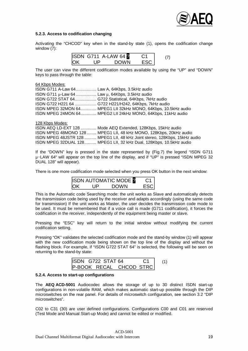
5.2.3. Access to codification changing Activating the “CHCOD” key when in the stand-by state (1), opens the codification changewindow (7):
The user can view the different codification modes available by using the “UP” and “DOWN”keys to pass through the table: 64 Kbps Modes: ISDN G711 A-Law 64................. Law A, 64Kbps, 3.5kHz audio ISDN G711 µ-Law 64 ................. Law µ, 64Kbps, 3.5kHz audio ISDN G722 STAT 64.................. G722 Statistical, 64Kbps, 7kHz audio ISDN G722 H221 64 .................. G722 H221/H242, 64Kbps, 7kHz audio ISDN MPEG 32MON 64............. MPEG1 LII 32kHz MONO, 64Kbps, 10.5kHz audio ISDN MPEG 24MON 64............. MPEG2 LII 24kHz MONO, 64Kbps, 11kHz audio
128 Kbps Modes: ISDN AEQ LD-EXT 128 ............. Mode AEQ Extended, 128Kbps, 15kHz audio ISDN MPEG 48MONO 128 ........ MPEG1 LII, 48 kHz MONO, 128Kbps, 20kHz audio ISDN MPEG 48JSTR 128 .......... MPEG1 LII, 48 kHz Joint stereo, 128Kbps, 15kHz audio ISDN MPEG 32DUAL 128.......... MPEG1 LII, 32 kHz Dual, 128Kbps, 10.5kHz audio If the “DOWN” key is pressed in the state represented by (Fig.7) the legend “ISDN G711µ− LAW 64“ will appear on the top line of the display, and if “UP” is pressed “ISDN MPEG 32DUAL 128” will appear). There is one more codification mode selected when you press OK button in the next window:
This is the Automatic code Searching mode: the unit works as Slave and automatically detectsthe transmission code being used by the receiver and adapts accordingly (using the same codefor transmission) If the unit works as Master, the user decides the transmission code mode tobe used. It must be remembered that if a voice call is made (G711 codification), it forces thecodification in the receiver, independently of the equipment being master or slave. Pressing the “ESC” key will return to the initial window without modifying the currentcodification setting. Pressing “OK” validates the selected codification mode and the stand-by window (1) will appearwith the new codification mode being shown on the top line of the display and without theflashing block. For example, if “ISDN G722 STAT 64” is selected, the following will be seen onreturning to the stand-by state:
5.2.4. Access to start-up configurations The AEQ ACD-5001 Audiocodec allows the storage of up to 30 distinct ISDN start-upconfigurations in non-volatile RAM, which makes automatic start-up possible through the DIPmicroswitches on the rear panel. For details of microswitch configuration, see section 3.2 “DIPmicroswitches”.
C02 to C31 (30) are user defined configurations. Configurations C00 and C01 are reserved(Test Mode and Manual Start-up Mode) and cannot be edited or modified.
(1)
(7)
ISDN G711 A-LAW 64 ? C1 OK UP DOWN ESC
ISDN G722 STAT 64 C1 P-BOOK RECAL CHCOD STRC
ISDN AUTOMATIC MODE ? C1 OK UP DOWN ESC

ACD-5001Dual Channel Multiformat Digital Audiocodec with Intercom 20
Codification information and the number to use for each communication channel is stored ineach configuration (Channel 1 – Channel 2), each register consists of three fields (LABEL,NUMBER and CODIFICATION) for each channel (1 and 2). Therefore, in one configurationregister it is possible to store one codification type with the number to dial for the Channel 1using a specific label, and one codification type and number to dial for the Channel 2 with adifferent label.
Important: Given that 128Kb codifications use both 64Kb channels, it is only possible to storethe information related to the Channel 1. The following explains the configuration register edition/modification procedure. Given thatediting the fields in a register is performed similarly to editing the ‘phone book, the procedurewill be roughly explained, with those aspects which differ to the edition/modification of the‘phone book being explained in more detail.
From the stand-by status (1), pressing the ”STRC” key will open window (8):
The first configuration register will appear on the top line of the display, with the correspondinglabel for the Channel 1. The “UP” and “DOWN” keys are used to select the register number required for display ormodification and storage in RAM. The “DOWN” key will present register C03, and the “UP” keywill present register C31. The “SELECT CHAN 1/CHAN 2” key is used to select the channel required for display/edition(C1/C2). Once the register and desired channel have been selected, the selection is validated with the“OK” key and passes on to the edit window (9). The “ESC” key will return to the stand-by state (1). Note: As the process of editing/modifying a start-up configuration is the same for both Channel1 and Channel 2, only the Channel 1 example is referred to here
Using the “ESC” key returns to window (8). The codification and ISDN number associated to the selected C1 circuit start-up configurationare visualised using the “CODIF” and “NUMB” keys. Windows similar to those of the ‘phonebook appear (3’). For example: “CODIF” “NUMB”
The “ESC” key will return to window (9).
The “EDIT” key is pressed to pass on to the edition/modification of the selected start-upconfiguration register. Editing is performed sequentially in a similar way to the ‘phone book register, in the order:Number (10), Label (11) and Codification (12).
(8)
C02 AEQ C1 OK UP DOWN ESC
C02 AEQ C1 EDIT CODIF NUMB ESC
(9)
ISDN G722 H221 64 C1 ESC
916857020 ESC
ACD-5001Dual Channel Multiformat Digital Audiocodec with Intercom 21
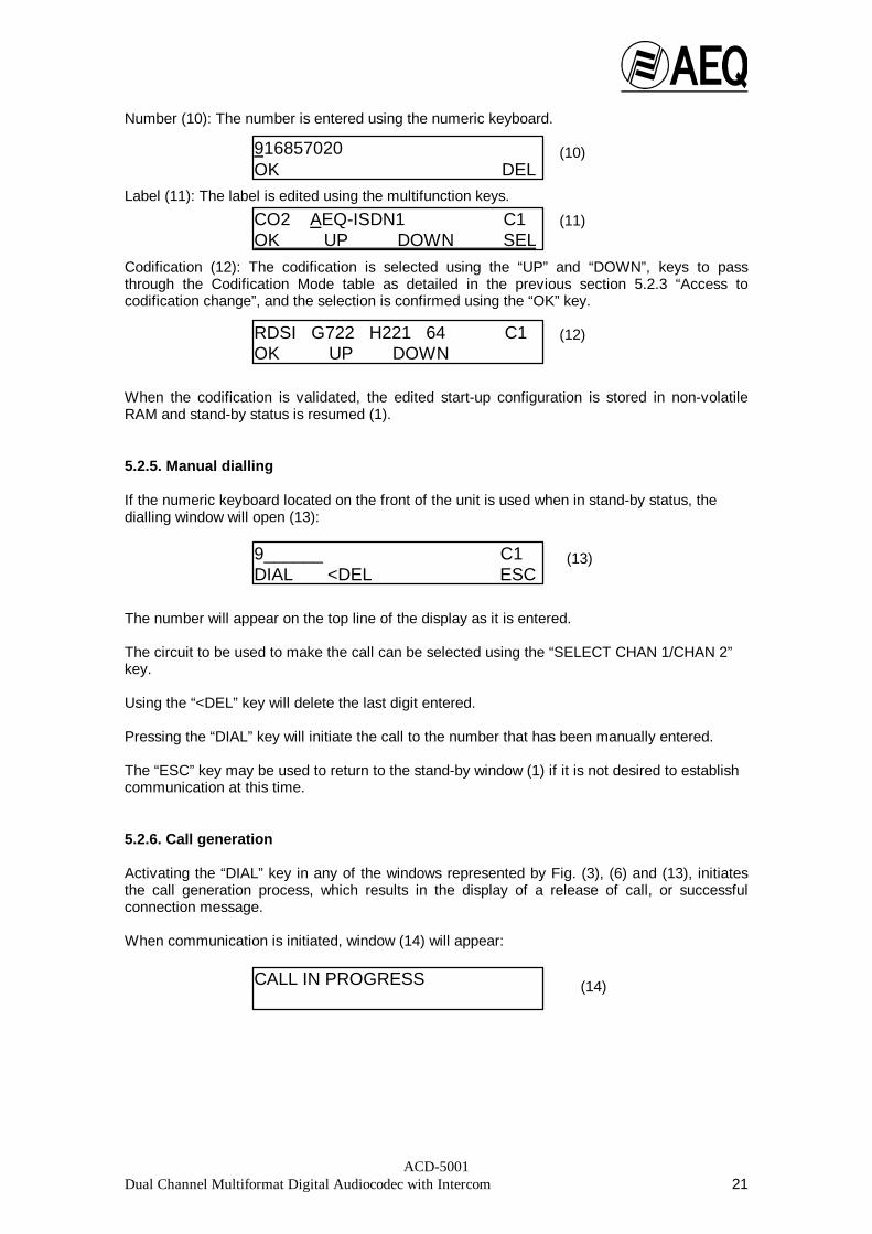
Number (10): The number is entered using the numeric keyboard.
Label (11): The label is edited using the multifunction keys.
Codification (12): The codification is selected using the “UP” and “DOWN”, keys to passthrough the Codification Mode table as detailed in the previous section 5.2.3 “Access tocodification change”, and the selection is confirmed using the “OK” key.
When the codification is validated, the edited start-up configuration is stored in non-volatileRAM and stand-by status is resumed (1). 5.2.5. Manual dialling
If the numeric keyboard located on the front of the unit is used when in stand-by status, thedialling window will open (13):
The number will appear on the top line of the display as it is entered.
The circuit to be used to make the call can be selected using the “SELECT CHAN 1/CHAN 2”key. Using the “<DEL” key will delete the last digit entered. Pressing the “DIAL” key will initiate the call to the number that has been manually entered.
The “ESC” key may be used to return to the stand-by window (1) if it is not desired to establishcommunication at this time. 5.2.6. Call generation
Activating the “DIAL” key in any of the windows represented by Fig. (3), (6) and (13), initiatesthe call generation process, which results in the display of a release of call, or successfulconnection message.
When communication is initiated, window (14) will appear:
(11)
(10)
916857020 OK ⇐ ⇒ DEL
CO2 AEQ-ISDN1 C1 OK UP DOWN SEL
RDSI G722 H221 64 C1 OK UP DOWN
9______ C1 DIAL <DEL ESC
CALL IN PROGRESS
(12)
(13)
(14)
ACD-5001Dual Channel Multiformat Digital Audiocodec with Intercom 22
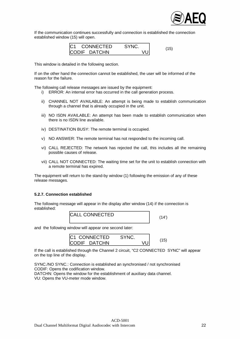
If the communication continues successfully and connection is established the connectionestablished window (15) will open.
This window is detailed in the following section. If on the other hand the connection cannot be established, the user will be informed of thereason for the failure.
The following call release messages are issued by the equipment:i) ERROR: An internal error has occurred in the call generation process.
ii) CHANNEL NOT AVAILABLE: An attempt is being made to establish communication
through a channel that is already occupied in the unit.
iii) NO ISDN AVAILABLE: An attempt has been made to establish communication whenthere is no ISDN line available.
iv) DESTINATION BUSY: The remote terminal is occupied.
v) NO ANSWER: The remote terminal has not responded to the incoming call.
vi) CALL REJECTED: The network has rejected the call, this includes all the remainingpossible causes of release.
vii) CALL NOT CONNECTED: The waiting time set for the unit to establish connection witha remote terminal has expired.
The equipment will return to the stand-by window (1) following the emission of any of theserelease messages. 5.2.7. Connection established The following message will appear in the display after window (14) if the connection isestablished:
and the following window will appear one second later:
If the call is established through the Channel 2 circuit, “C2 CONNECTED SYNC” will appearon the top line of the display. SYNC./NO SYNC.: Connection is established an synchronised / not synchronised CODIF: Opens the codification window. DATCHN: Opens the window for the establishment of auxiliary data channel. VU: Opens the VU-meter mode window.
(15)
C1 CONNECTED SYNC. CODIF DATCHN VU
CALL CONNECTED (14’)
C1 CONNECTED SYNC. CODIF DATCHN VU
(15)

ACD-5001Dual Channel Multiformat Digital Audiocodec with Intercom 23
5.2.7.1. Data Channel
This is a transparent bi-directional point-to-point 1200 baud channel.For the channel to operate correctly, the transmission configurationshould be set to: 1200 bauds No parity 8 data bits 1 stop bit The data channel can be established in relation to the codification mode being used inthe established connection.
- An auxiliary data channel may be established in the following modes:• Mode 64:
-G722 H221/H242, 64Kbps-MPEG 32 MONO, 64Kbps-MPEG 24 MONO, 64Kbps
• Modes 128:
-MPEG 48 MONO, 128Kbps -MPEG 48 JSTR, 128Kbps -MPEG 32 DUAL, 128Kbps
- Modes which do not accept auxiliary data channels:
• The remaining modes shown in the table in section 5.2.3 The following message will be displayed for one second if the ”DATCHN” key isoperated in window (15) while using a mode that does not allow the establishment of adata channel:
and then return to window (15). If the “DATCHN” key is activated while using mode 64, which permits the establishmentof a data channel, window (16) is opened
Pressing the “ESC” key will return to window (15). When window (16) is opened, the cursor appears on the letter “P” of Program circuit,indicating that this channel is selected by default. The other channel may be selectedby pressing the “CHANN” key, and the cursor will pass to the letter “C” of Co-ordinationcircuit. Pressing the “Rx” and “Tx” keys activates (On) or deactivates (Off) the transmission(Tx) or reception (Rx) of the corresponding data channel to the channel that is currentlyactive. Given that there is only one data channel available, only one data transmission andone data reception can be established simultaneously, that is to say, if one channel(e.g. Program) is transmitting, the other channel (Co-ordination) can only receive, andvice-versa; if one channel is simultaneously transmitting and receiving data, the othercannot be used for either transmission or reception, because the data channel isalready occupied. If this is the case and an attempt is made to activate the other channel to transmit orreceive data, the equipment will reject the request and display the window:
DATA CHANNEL NOT AVAILABLE
C1: TXof RXof C2: TXof RXofCHANN RX TX ESC
(16)
ACD-5001Dual Channel Multiformat Digital Audiocodec with Intercom 24
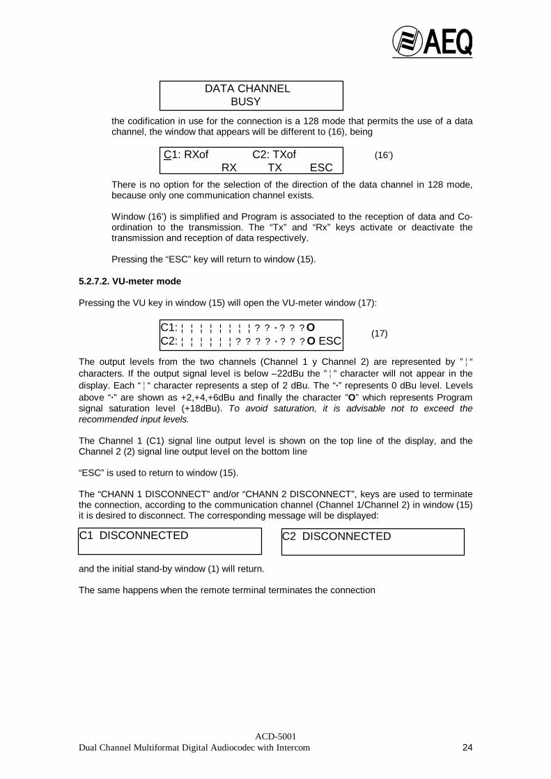
the codification in use for the connection is a 128 mode that permits the use of a datachannel, the window that appears will be different to (16), being
There is no option for the selection of the direction of the data channel in 128 mode,because only one communication channel exists. Window (16’) is simplified and Program is associated to the reception of data and Co-ordination to the transmission. The “Tx” and “Rx” keys activate or deactivate thetransmission and reception of data respectively. Pressing the “ESC” key will return to window (15).
5.2.7.2. VU-meter mode Pressing the VU key in window (15) will open the VU-meter window (17):
The output levels from the two channels (Channel 1 y Channel 2) are represented by ”¦“characters. If the output signal level is below –22dBu the ”¦” character will not appear in thedisplay. Each “¦“ character represents a step of 2 dBu. The “·” represents 0 dBu level. Levelsabove “·” are shown as +2,+4,+6dBu and finally the character ”O” which represents Programsignal saturation level (+18dBu). To avoid saturation, it is advisable not to exceed therecommended input levels. The Channel 1 (C1) signal line output level is shown on the top line of the display, and theChannel 2 (2) signal line output level on the bottom line “ESC” is used to return to window (15). The “CHANN 1 DISCONNECT” and/or “CHANN 2 DISCONNECT”, keys are used to terminatethe connection, according to the communication channel (Channel 1/Channel 2) in window (15)it is desired to disconnect. The corresponding message will be displayed:
and the initial stand-by window (1) will return. The same happens when the remote terminal terminates the connection
(16’)
(17)
DATA CHANNEL BUSY
C1 DISCONNECTED C2 DISCONNECTED
C1: RXof C2: TXof RX TX ESC
C1: ¦ ¦ ¦ ¦ ¦ ¦ ¦ ¦ ? ? · ? ? ? O C2: ¦ ¦ ¦ ¦ ¦ ¦ ? ? ? ? · ? ? ? O ESC

ACD-5001Dual Channel Multiformat Digital Audiocodec with Intercom 25
5.2.8. Receiving Calls:
The Audiocodec allows operation in two different call reception modes for each channel.Automatic Mode, the incoming call is automatically connected simply by the receipt of the call,and Manual Mode, where the receipt of a call is indicated by an audible signal. The displayindicates which channel carries the call and the number making the call, permitting the operatorto choose whether to answer.
Pressing the "OFFHK" key answers and connects the incoming call.
In Automatic mode, the equipment connects the incoming call directly. 5.3. Generation of DTMF tones for remote control. It is possible to generate and send DTMF tones to line to effect remote control operations whenoperating in ISDN mode and in connection established status (4). It is necessary to press andhold the “HOLD FOR DTMF” key and at the same time press the corresponding digit on thekeyboard. The audio Program is cut during tone generation. DTMF dialling mode must be used to establish the call for this function to work correctly.
INCOMING CALL CHANNEL 1OFFHK 917954352

ACD-5001Dual Channel Multiformat Digital Audiocodec with Intercom 26
6. UPGRADING THE INTERNAL SOFTWARE (FIRMWARE UPGRADE): This section describes the procedure to upgrade the AEQ ACD-5001 Audiocodec internalsoftware. 6.1. System description The system allows the internal software in the three basic AEQ ACD-5001 modules to beupgraded, i.e. the Microprocessor, Terminal Adapters (TAs) and Digital Signal Processors(DSPs). 6.2. Requirements of the PC used for upgrading The system requirements are determined by the Operative System in use: Windows 95 orWindows NT . These operative systems dictate the computer’s minimum processor andavailable RAM memory specifications. With Windows 95 the minimum configuration is aPentium family processor with 16 MB RAM memory. The software installation requires 3 MBhard disk space and up to 20 MB for user configurations. A mouse and a free serial port arealso required. 6.3. Connections for computer control A female connector, labelled “CONTROL PORT”, is mounted on the rear of the Audiocodecchassis for connection to an external computer communicating through RS-232 protocol. ThePC is connected through its serial port. The connections are as follows:
RX 2 TX 3 GND 5
The pins connecting the Audiocodec and PC are as follows:
ACD-5001 : DB-9 MALE PC : DB-9 FEMALE 2 -------------------------------------- 2 3 -------------------------------------- 3 5 -------------------------------------- 5
ACD-5001 : DB-9 MALE PC : DB-25 FEMALE 2 -------------------------------------- 3 3 -------------------------------------- 2 5 -------------------------------------- 7
6.4 Firmware upgrading The operation to upgrade the firmware is very simple. A floppy-disk is available for Firmwareupgrading. Important: Ensure that the start-up configuration is NOT set to Test Mode. Also, the equipmentcannot be used for any other operation, such as making a call etc., during the process ofupgrading the Firmware. The upgrading procedure is as follows: Before commencing the upgrading process, the PC and AEQ ACD-5001 must beinterconnected using the PC serial port and the AEQ ACD-5001 Control port as previouslydescribed. Then, the “ACD-5001 Firmware Upgrade” Program must be installed into your system like anyother Windows application. Just follow the instructions contained in the floppy.

ACD-5001Dual Channel Multiformat Digital Audiocodec with Intercom 27
Fig. 7.2. Without communication
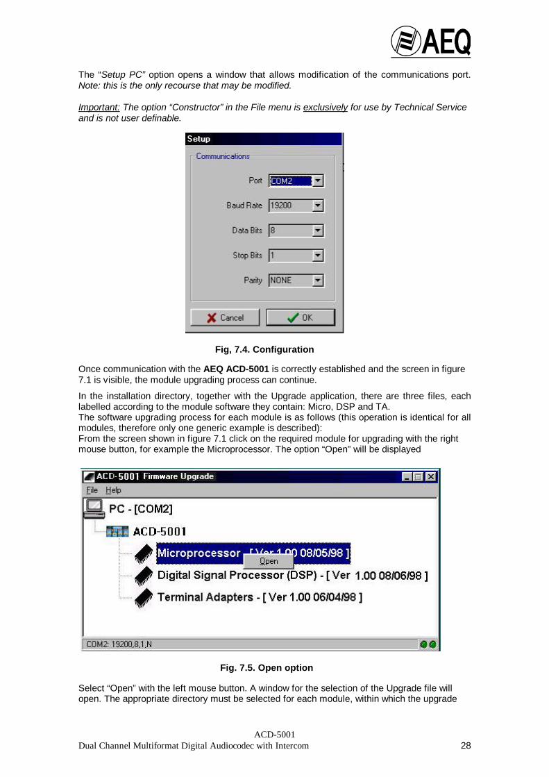
Setup Program creates an icon on your desktop PC called “ACD-5001 Firmware Upgrade”. Runthe application “ACD-5001 Firmware Upgrade”, whereupon the following screen will be seen:
If communication is correctly established with the AEQ ACD-5001, the screen shows the threebasic modules, the Microprocessor, Digital Signal Processor (DSP) and Terminal Adapters,each with the current Firmware version and date (e.g. Microprocessor - (Ver 1.00 08/05/98)).Luminous indicators in the bottom right hand corner of the screen display the state ofcommunication between the PC and AEQ ACD-5001. (They should be green and blinking). Theserial channel communication parameters are displayed in the bottom left hand corner of thescreen.
If communication is not established correctly, the user must indicate the port to be used forcommunication.
The corresponding screen is:
Fig. 7.1. ACD-5001 Firmware Upgrade screen
Fig. 7.3. File menu
Access must be gainedthrough the “File –Setup PC” menu toconfigure thecorrespondingcommunication port.
ACD-5001Dual Channel Multiformat Digital Audiocodec with Intercom 28
The “Setup PC” option opens a window that allows modification of the communications port.Note: this is the only recourse that may be modified. Important: The option “Constructor” in the File menu is exclusively for use by Technical Serviceand is not user definable.
Once communication with the AEQ ACD-5001 is correctly established and the screen in figure7.1 is visible, the module upgrading process can continue.
In the installation directory, together with the Upgrade application, there are three files, eachlabelled according to the module software they contain: Micro, DSP and TA. The software upgrading process for each module is as follows (this operation is identical for allmodules, therefore only one generic example is described): From the screen shown in figure 7.1 click on the required module for upgrading with the rightmouse button, for example the Microprocessor. The option “Open” will be displayed
Select “Open” with the left mouse button. A window for the selection of the Upgrade file willopen. The appropriate directory must be selected for each module, within which the upgrade
Fig, 7.4. Configuration
Fig. 7.5. Open option

ACD-5001Dual Channel Multiformat Digital Audiocodec with Intercom 29
file for each module can be found. The Upgrading Microprocessor File is supplied in bothlanguages, English (Ming~) and Spanish (Micr~).
Once the file with the latest software version is selected, the Upgrade window opens:
The current AEQ ACD-5001 module software version is shown in the bottom left section of thewindow, and the version for the upgrade in the right.
The “Upgrade” button is pressed to proceed with the software upgrade.
Fig. 7.6. Open Upgrade File
Fig. 7.7. Upgrade screen

ACD-5001Dual Channel Multiformat Digital Audiocodec with Intercom 30
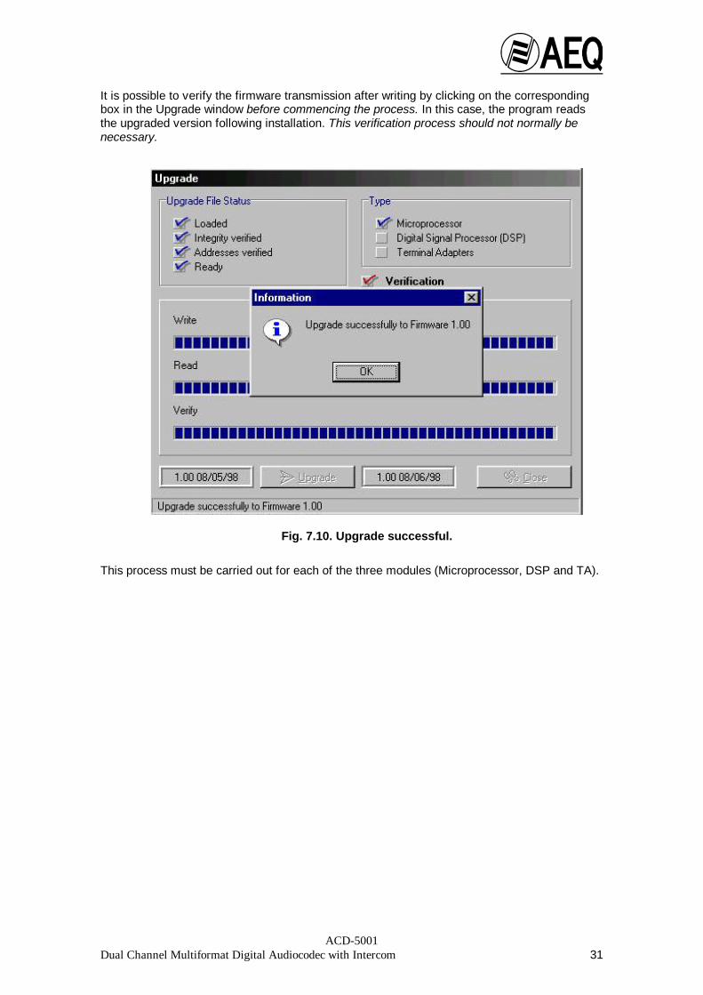
A progress indicator appears that shows the time remaining to complete the process
After writing (and verification when selected), the Upgrade program will confirm that theprocess has been successfully completed:
Fig. 7.8. Upgrading process
ACD-5001Dual Channel Multiformat Digital Audiocodec with Intercom 31
It is possible to verify the firmware transmission after writing by clicking on the correspondingbox in the Upgrade window before commencing the process. In this case, the program readsthe upgraded version following installation. This verification process should not normally benecessary.
This process must be carried out for each of the three modules (Microprocessor, DSP and TA).
Fig. 7.10. Upgrade successful.

ACD-5001Dual Channel Multiformat Digital Audiocodec with Intercom 32
8. ACD-5001 TECHNICAL SPECIFICATIONS
• Microphone input (transformer balanced):
• Input impedance: >3KΩ• Nominal input level for GO = 0dBu : -60dBu
• Maximum input level for nominal adjustment: -35dBu
• Input range for GO = 0dBu : -70dBu ÷ -50dBu
• Bandwidth: 20Hz ÷ 20kHz -1.7dB
• EIN: (G= 60dB; Absolute noise = -58dBu) = -118dBu (with BPF)
• EIN: (G= 70dB; Absolute noise = -50dBu) = -120dBu (with BPF)
• Line inputs CHANNEL 1 IN and CHANNEL 2 IN (transformer balanced):
• Input impedance: >6K5Ω• Nominal input level for GO = 0dBu: 0dBu
• Maximum input level for nominal adjustment: +26dBu
• Input range for GO = 0dBu: -10dBu ÷ +10dBu
• Bandwidth: 20Hz ÷ 20kHz -1dB
• Outputs 1 and 2 (transformer balanced):
• Output impedance: <75Ω• Nominal output level: 0dBu
• Maximum output level: +16dBu
• Absolute noise (with all sends cut):
SEND (GO): -73dBu RETURN (F’BACK): -63dBu
• Headphone outputs:
• Nominal load impedance: 2 x 600Ω• Nominal output level (potentiometer at maximum): +10dBu
• Maximum output level: +12dBu
• Output absolute noise (pot. at maximum, sends cut): -82dBu
• Output power (into 600Ω): 16mW
• Crosstalk (20Hz ÷ 20kHz):
• CHANNEL 1 - CHANNEL 2 (nominal adjustment): <-75dB
• Channel 1 over Microphone (nominal adjustment,
microphone input load 200Ω):<-60dB
• Channel 2 over Microphone (nominal adjustment,
microphone input load 200Ω):<-45dB• Approximate dimensions:
• Width: 19’’ (42 cm)
• Height: 2 U (9 cm)
• Depth: 24 cm
• Weight: 4 Kg (approx.)

ACD-5001Dual Channel Multiformat Digital Audiocodec with Intercom 33
APPENDIX 1: GUIDE TO RAPID USE To establish communication:
When calls are made over ISDN digital lines, the AEQ ACD-5001 is capable ofcommunicating through two independent 64Kb channels, one for program and the otherfor orders. Once connection is established in one channel, the second channel may beconnected. The destination selector (SELECT CHAN1/CHAN2) situated on the left of the numerickeyboard must be pressed to select the desired channel (Channel 1/Channel 2) for theconnection. The channel selected will be shown in the top right corner of the LCDdisplay. By default, the Program will be passed to the channel used for the initialdialling, and Co-ordination to the second channel.
Manual call: • Select the necessary transmission codification (if not the one shown in the display)
by pressing the corresponding CHCOD (Change Codification) key.• Press UP - DOWN to select the required code.
The codification must be the same as used by the remote equipment forcommunication.
• Press OK (Validate) to set the selected codification.• Dial the desired telephone number using the numeric keyboard.• Press the DIAL key to initiate the dialling process. The message CALL IN PROGRESS appears in the display during the establishment ofa call. If the communication is successfully realised, the message CALL CONNECTEDwill appear. If the call fails, an error message will appear indicating the possible cause. The dialling process for the second channel is the same as described above.
Automatic call:
• Select the P-BOOK key in the display.• Using the UP – DOWN keys, look for the required telephone number.• Press the OK key to select the required number.• Press the DIAL key to initiate the dialling process.
.If the call is not established at the first attempt (line busy, no reply) and independent ofthe mode being used (manual or automatic), redial may be effected using the RECALoption where the last number dialled will be stored.
To disconnect the unit from the ISDN line, the button corresponding to the channel fordisconnection (CHANN 1 DISCONNECT or CHANN 2 DISCONNECT) situated at theleft of the numeric keyboard must be pressed. In ISDN 128Kb mode (using both 64Kbchannels) pressing either of the two buttons will disconnect the equipment.
VU mode (VU-meter) may be selected to monitor the output signal level once communicationhas been established.

ACD-5001Dual Channel Multiformat Digital Audiocodec with Intercom 34
V.35/V.11 OR V.24 INTERFACE
DB25 CONNECTOR PINOUT:
The DB25 Female connector admits 2 types of external Terminal Adapters:
- V35 interface (V11): Uses unbalanced asynchronous control signals, while synchronous clockand data signals are balanced.
- V24 interface: It is a synchronous RS232.
These 2 types of connection share some signals, so both types share the same DB25connector:
PIN V.35 (V11) SIGNALS V.24 SIGNALS1 SPARE SPARE2 NOT USED TX TRANSMITED DATA3 NOT USED RX RECEIVED DATA4 RTS REQUEST TO SEND RTS REQUEST TO SEND5 CTS CLEAR TO SEND CTS CLEAR TO SEND6 SPARE SPARE7 GND SIGNAL GROUND GND SIGNAL GROUND8 DCD DATA CARRIER DETECT DCD DATA CARRIER DETECT9 SPARE SPARE10 TX V- TRANSMITTED DATA B NOT USED11 TX V+ TRANSMITTED DATA A NOT USED12 SPARE SPARE13 RCX V+ SERIAL CLOCK RECEIVE A NOT USED14 RCX V- SERIAL CLOCK RECEIVE B NOT USED15 SPARE SPARE16 SPARE SPARE17 NOT USED RXC RECEIVE CLOCK18 SPARE SPARE19 RX V- RECEIVED DATA A NOT USED20 DTR DATA TERMINAL READY DTR DATA TERMINAL READY21 RX V+ RECEIVED DATA B NOT USED22 SPARE SPARE23 SPARE SPARE24 SPARE SPARE25 SPARE SPARE
“SPARE” means that there is no signal available on this pin.“NOT USED” means that this pin has a signal which is not used in this type.

ACD-5001Dual Channel Multiformat Digital Audiocodec with Intercom 35
CONNECTIONS:
There are 3 types of connections that can be used through this interface:
NOTE: This connections depend on external equipment and there is no standard cablefor all of them. In this document we just show pinout, signals and the way to connect it.
ANNEX 2.1 V.24 CONNECTION TO AN EXTERNAL TERMINAL ADAPTER WITH CALLMANAGEMENT.
An external T.A. (ISDN) can be used. Pinout and signals in the cable would be:
CCITT DESCRIPTION DTE ACD5001 EXTERNAL TA * DCE102 SIGNAL GROUND GND 7 GND103 TRANSMITTED DATA TX 2 TXD104 RECEIVED DATA A RX 3 RXD105 REQUEST TO SEND RTS 4 RTS106 CLEAR TO SEND CTS 5 CTS108 DATA TERMINAL READY DTR 20 DTR109 DATA CARRIER DETECT DCD 8 DCD115 RX. CLOCK RXC 17 RXC
* This information has to be found in the external T.A. manual.
This mode can be only used in 64Kbps modes.
OPERATING MODE:
When codec starts and detects a v.24 connection in the interface, it will show a message in thedisplay and will connect to the T.A.:
Connection starts by default in G722 STAT. It is possible to change it by pushingDISCONNECT CHANN 1 button, selecting the new 64kbps mode and then accepting it. Thisoperation has to be made in both codecs.
EXTERNAL T.A. CONNECTEDINTERFACE V.24 64k
C1 CONNECTED SYNC.CODIF DATCHA VU

ACD-5001Dual Channel Multiformat Digital Audiocodec with Intercom 36
V.35 CONNECTION TO AN EXTERNAL TERMINAL ADAPTER WITH CALLMANAGEMENT.
In the same way, an external ISDN T.A. can be connected through v.35. Signals in the cablewould be:
CCITTDESCRIPTION DTE ACD5001 N.T.U. ** DCE
102 SIGNAL GROUND GND 7 B GND103 TRANSMITTED DATA A TXD A 11 P TXD A
TRANSMITTED DATA B TXD B 10 S TXD B104 RECEIVED DATA A RXD A 21 R RXD A
RECEIVED DATA B RXD B 19 T RXD B105 REQUEST TO SEND RTS 4 C RTS106 CLEAR TO SEND CTS 5 D CTS108 DATA TERMINAL READY DTR 20 H DTR109 DATA CARRIER DETECT DCD 8 F DCD115 RX. CLOCK V+ SCR A 13 V SCR A
RX. CLOCK V- SCR B 14 X SCR B
** The pinout showed corresponds to ISO-2593 standard in a MRAC-34 connector.
That mode can be only used in 64Kbps circuits.
OPERATING MODE:
When codec starts and detects a v.34/v11 connection in the interface, it will show a message inthe display and will connect to the T.A.:
Connection starts by default in G722 STAT. It is possible to change it by pushingDISCONNECT CHANN 1 button, selecting the new 64kbps mode and then accepting it. Thisoperation has to be made in both codecs.
EXTERNAL T.A. CONNECTEDINTERFACE V.34 64k
C1 CONNECTED SYNC.CODIF DATCHA VU

ACD-5001Dual Channel Multiformat Digital Audiocodec with Intercom 37
V.35 CONNECTION TO A LEASED (Point-to-Point) LINE.
The codec can be connected to another codec through a leased line using a v.35 interface.This would be the pinout and signals in the cable connecting the codec to the NetworkTerminating Unit:
CCITTDESCRIPTION DTE ACD5001 N.T.U. ** DCE
102 SIGNAL GROUND GND 7 B GND103 TRANSMITTED DATA A TXD A 11 P TXD A
TRANSMITTED DATA B TXD B 10 S TXD B104 RECEIVED DATA A RXD A 21 R RXD A
RECEIVED DATA B RXD B 19 T RXD B115 RX. CLOCK V+ SCR A 13 V SCR A
RX. CLOCK V- SCR B 14 X SCR B
** The pinout showed corresponds to ISO-2593 standard in a MRAC-34 connector.Contact your line provider to make sure which standard is using.
That mode can be used in a single 128 or 64Kbps leased line connection. Detection isautomatic.
IMPORTANT: In this operating mode, microswitch #3 has to be UP, and both codecs have to be upgraded toa software version equal or higher to the one published the 4th of August of 2000.
Software versions can be downloaded from AEQ web page, clicking “Technical Support” link:http://www.aeq.es/
OPERATING MODE:
When codec starts and detects a v.34/v11 connection in the interface, it will show a message inthe display and will connect to the T.A.:
Connection starts by default in G722 STAT for 64kbps or AEQ LD EXTEND for 128kbps. It ispossible to change it by pushing DISCONNECT CHANN 1 button, selecting the new 64kbps or128kbps mode and then accepting it. This operation has to be made in both codecs.
EXTERNAL T.A. CONNECTEDINTERFACE V.34 64k
C1 CONNECTED SYNC.CODIF CANDAT VU

ACD-5001Dual Channel Multiformat Digital Audiocodec with Intercom 38
TROUBLESHOOTING LEASED LINE CONNECTIONS.
This is the basic diagram of a bi-directional communication between two distant points. In eachone there are two signals, A and B:
Between A point and B point, there is a leased line and two Network Terminating Units (NTUs)or Terminal Adapters (TAs) which are usually rented to a Telecommunications Company (PTT).In some cases, this adapters allow performing some easy tests which helps checking the line incase of problems.
Before checking the line, it is necessary to check codec status:
I) DIP Microswitches:
Microswitch 3 must be UP in point-to-point (no call management) connections.Microswitches must have the same configuration in both codecs.See more information in chapter 3.
II) Switches OUT SELECT.
To put incoming signal from remote point into a mixer through the XLR’s, it is necessary to putswitches in F’B position. See more information in chapter 3.2.
III) Software Version and Audio Format.
Software Version and Audio Format must be the same in both codecs. Line speed (64 or128kbps) limits the number of audio formats available.It is not possible to use a 64kbps mode in a 128kbps connection, and the same for a 128kbpsmode in a 64kbps line.
IV) Automatic Start-up configurations
It is possible to use an automatic start-up configuration in leased line operation. In this case,phone number stored in memory is ignored.
V) VOICE FORMATS:
A-Law and µ-Law formats can not be used in leased line connections.

ACD-5001Dual Channel Multiformat Digital Audiocodec with Intercom 39
VI) CHECKING LEASED LINES:
In case of problems, it is possible to perform some easy tests to the line. Before doing this,note that in most cases, line and terminals are property of the PTTs, so it would be necessaryto ask them for help to perform some of this tests.
The tests are performed by putting loops in different points of the line.
• INTERNAL LOOP
To perform this test:- Put OUT SELECT SWITCHES in GO position.- Put audio signal in ‘CH1 IN’ XLR.- Listen to ‘CH1 OUT’ XLR.This test can be done in both codecs (Remember to put it again in F’B position).
This test only can be useful to make sure that incoming “A” signal is fine. If not, check patchpanel and cables.
• INTERFACE LOOP
To do this test:
- Activate the loop.- Put audio signal in ‘CH1 IN’ XLR.- Listen to ‘CH1 OUT’ XLR.This test can be done in both codecs .
In that case, there is a loop in the interface of the local N.T.U. or T.A. . The cable and bothinterfaces are checked.

ACD-5001Dual Channel Multiformat Digital Audiocodec with Intercom 40
• LINE LOOP.
The loop is in the remote N.T.U. or T.A., but note that this loop is to the line, not to theinterface.If this test is fine, all the line is verified.
• For more questions, contact our Technical Assistance Service: [email protected]• NTUs and TAs:
As an example, some of this devices usually have some lights which can be used to knowcommunication status. For example, they could be:
103 light refers to Transmitted Data. It must be ON.104 light refers to Received Data. It must be ON.107 light refers to Synchronism. It must be ON.
Sometimes, these devices have some buttons for making loops.
Each PTT uses its owns terminals, contact your company for specific information.

ACD-5001Dual Channel Multiformat Digital Audiocodec with Intercom 41
APPENDIX 2: Compatibility with TELOS y CCS audiocodecs.
For the AEQ ACD-5001 to be compatible with TELOS (ZEPHYR) and CCS (CDQ PRIMA)audiocodecs in all 128Kbps modes, IMUX multiplex should be selected using microswitch 2found on the rear panel of the AEQ ACD-5001. This microswitch should be set in the uppositioned. Once the AEQ ACD-5001 has been reset, check the multiplex shown on thedisplay. See also section 3.2.
• Compatibility with TELOS/ZEPHYR64 Kbps Modes: G711 Law A G722 Statistical MPEG LII, 64Kbps, 24kHz
128Kbps Modes: MPEG LII MONO, 128Kbps, 48 kHz MPEG LII JOINT STEREO, 128Kbps, 48 kHzMPEG LII STEREO, 128Kbps, 48 kHz
ZEPHYR can generate voice calls, but it can not receive them.
• Compatibility with CCS/CDQ PRIMA64 Kbps Modes: G722 Statistical MPEG LII MONO, 64Kbps, 24kHz MPEG LII MONO, 64Kbps, 32kHz
128Kbps Modes: MPEG LII MONO, 128Kbps, 48 kHz MPEG LII JOINT STEREO, 128Kbps, 48 kHz MPEG LII STEREO, 128Kbps, 48 kHz MPEG LII DUAL, 128Kbps, 32 kHz
Note: the CDQ PRIMA audiocodec should be configured with the following parameters:• configure as an independent decoder• the header menu configuration:
- Protect (transmits with CRC)- Original (ON)- ISO Algorithm
• CCSIMUX transmission mode, if using 128Kbps mode
ACD-5001Dual Channel Multiformat Digital Audiocodec with Intercom 42
APPENDIX 3: AEQ WARRANTY
A.E.Q. S.A. warrants, for one year period from the purchase date of the equipment, the freesubstitution at our Technical Service workshops, of any damaged or defective component dueto manufacture error, including the labour required to carry on such substitution and thesubsequent adjustment of the equipment.
This warranty does not include transport, installation and setting of the equipment, nor cleaningor substitution of pieces subject to normal operative wear.
This warranty also excludes any kind of failure or damage which are attributable to theimproper use of the equipment, or to the handling by persons outside our Technical Service.