accurate land mine modeling using fem & sph … · accurate land mine modeling using fem &...
TRANSCRIPT
UNCLASSIFIED: Distribution Statement A. Approved for public release; distribution is unlimited.
UNCLASSIFIED: Distribution Statement A. Approved for public release; distribution is unlimited. Material reported in this paper are results of Contract # M67854-13-C-0225 and have been cleared for public release by the USMC.
2017 NDIA GROUND VEHICLE SYSTEMS ENGINEERING AND TECHNOLOGY
SYMPOSIUM MODELING & SIMULATION, TESTING AND VALIDATION (MSTV) TECHNICAL SESSION
AUGUST 8-10, 2017 - NOVI, MICHIGAN
ACCURATE LAND MINE MODELING USING FEM & SPH WITH MODIFIED SMOOTHING LENGTH
Matt Barsotti
Eddie O’Hare, Ph.D. Eric Sammarco, Ph.D., P.E.
Protection Engineering Consultants Austin, TX
James G. Rasico David Gerst
Craig A. Newman Navistar Defense
Madison Heights, MI
ABSTRACT Accurate land mine modeling has been the subject of substantial research
over the past 15 years. Many methods have been investigated using various computational codes, and LS-DYNA remains a popular choice because of its capabilities for modeling full armored vehicles. Prior research discloses a range of strategies that have been utilized, including various numerical methods such as FEM, ALE, SPH, and DEM. This paper discusses a hybrid FEM-SPH land mine modeling approach using LS-DYNA that provides high accuracy at reasonable computational expense. While stable and phenomenologically correct, accuracy issues persisted with this approach, which tended to produce the typical SPH under-prediction of impulse. However, adjusting two key parameters– smoothing length and coefficient of restitution– were found to resolve the impulse under-prediction. The final land mine modeling strategy provided an accurate all-Lagrangian approach for application to full-scale vehicle models in LS-DYNA, whose predictive accuracy rivals that of the ALE.
INTRODUCTION
Background Accurate land mine modeling has been the
subject of substantial research over the past 15 years. Many methods have been investigated using various computational codes, and LS-DYNA remains a popular choice because of its capabilities for modeling full armored vehicles.
Prior research discloses a range of strategies that have been utilized, including various numerical
methods such as Finite Element Method (FEM), Arbitrary Lagrangian Eulerian (ALE), Smooth Particle Hydrodynamics (SPH) and the Discrete Element Method (DEM). Each of these strategies carries advantages and drawbacks. During prior research [1,2], Protection Engineering Consultants (PEC) carried out a significant comparison of these methods. The pure FEM method requires element erosion for soil ejecta, and it suffers both in terms of accuracy and explicit time step

UNCLASSIFIED: Distribution Statement A. Approved for public release; distribution is unlimited.
Proceedings of the 2017 Ground Vehicle Systems Engineering and Technology Symposium (GVSETS)
Accurate Land Mine Modeling Using FEM & SPH With Modified Smoothing Length
UNCLASSIFIED: Distribution Statement A. Approved for public release; distribution is unlimited. Material reported in this paper are results of Contract # M67854-13-C-0225 and have been cleared for public release by the USMC.
Page 2 of 17
reduction. The ALE method can provide high accuracy, but it is prone to fluid-structure leakage problems and tends to be computationally expensive. The SPH method offers a stable, all-Lagrangian solution with no leakage issues, but it tends to under-predict impulse compared to ALE and can be very expensive at finer discretization.
Regardless of the modeling strategy used, the accuracy of land mine blast loads is strongly driven by the fidelity of the soil material model. Since most benchmark land mine tests have been performed on sandy soils of varying moisture contents, ranging from dry to fully saturated, previous modeling efforts were focused on sandy soil model development.
Sandy Soil Material Model PEC previously developed a soil modeling
strategy for LS-DYNA that resulted in excellent agreement with data from carefully controlled, precision tests [3]. This model requires only two inputs from the user: dry sand density and moisture content.
The baseline material properties used to represent sandy soils were derived from two primary sources. The majority of the properties were based upon Sjobo sand, as characterized by Laine & Sandvik [4], which included compaction, strength, and modulus. Yield strength properties for varying levels of saturation were derived from Kerley [5,6]. These properties were combined with a Gruneisen equation of state for water using a three-spring compaction model approach, as illustrated in (Figure 1) [1,2].
In LS-DYNA, the soil was modeled using two
keywords. The elastic properties and yield strength were modeled with *MAT_PSEUDO_TENSOR. The strength versus pressure yield surface was defined as a simple bilinear curve with a maximum strength plateau per Kerley. The compaction behavior and unloading modulus were defined using the equation of state *EOS_TABULATED_COMPACTION.
For validation purposes, models were constructed to recreate land mine plate impact tests as conducted by the Ernst Mach Institute (EMI), per Anderson [7] and the Army Research Laboratory (ARL) and Aberdeen Proving Ground (APG), per Skaggs [8]. The three-spring soil model accurately reproduced the land mine impulse against all plate geometries of the EMI tests and at all water content levels, when modeled with ALE (Figure 2, Figure 3, and Figure 4). As shown, the predicted impulses fell within the experimental scatter of each test case.
Figure 1. Element Schematic of Three-Spring Compaction Model
KV
KW
KS
VoidFraction
SilicaFraction
WaterFraction

UNCLASSIFIED: Distribution Statement A. Approved for public release; distribution is unlimited.
Proceedings of the 2017 Ground Vehicle Systems Engineering and Technology Symposium (GVSETS)
Accurate Land Mine Modeling Using FEM & SPH With Modified Smoothing Length
UNCLASSIFIED: Distribution Statement A. Approved for public release; distribution is unlimited. Material reported in this paper are results of Contract # M67854-13-C-0225 and have been cleared for public release by the USMC.
Page 3 of 17
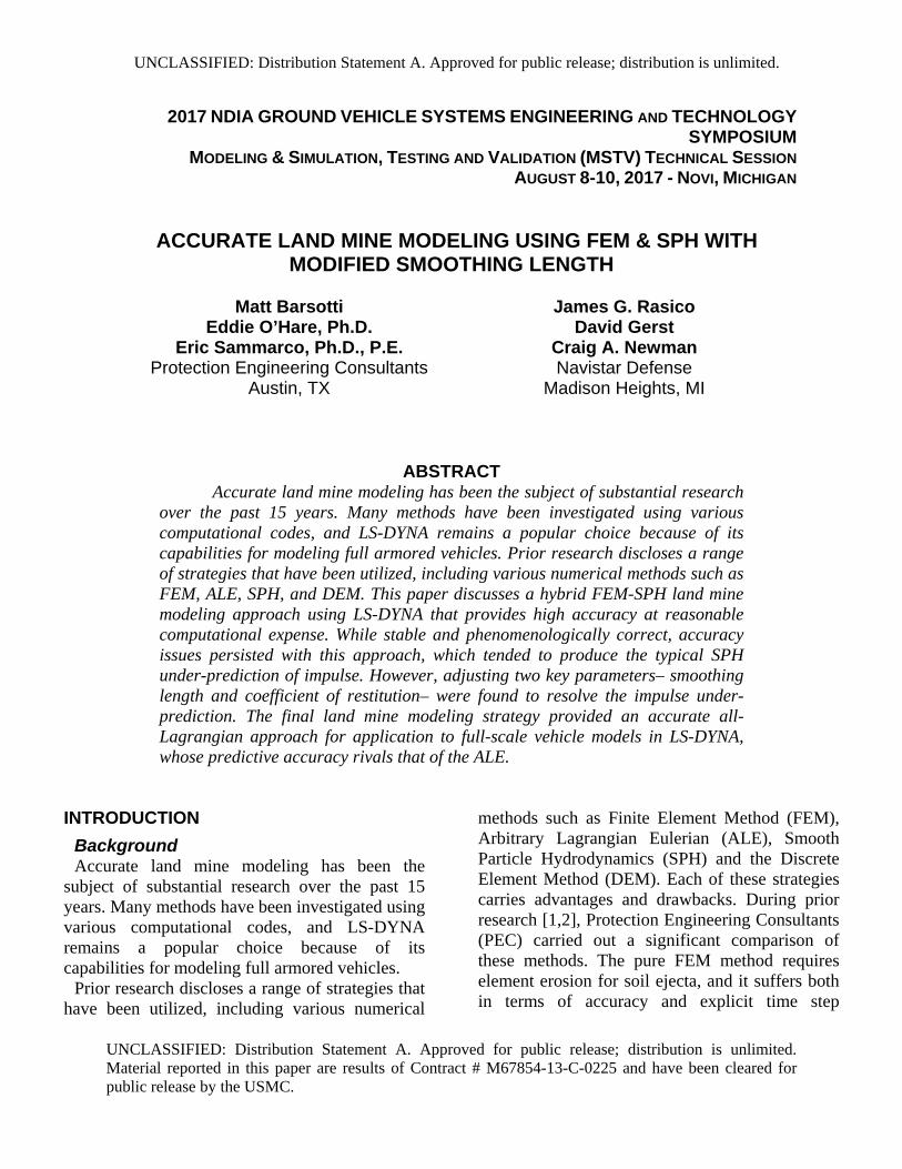
Using the same high-accuracy soil model, the
EMI test cases were modeled again using the SPH formulation (Figure 5). Although the granular behavior of SPH mimics that of actual soil better than the fluid ALE, the SPH strategy proved to be computationally expensive and substantially under-predicted the plate impulse (Figure 6). The shortfall in SPH performance, while using an otherwise accurate material model, motivated the development described in this paper.
Figure 2. ALE Response Evolution for EMI 120-deg and Flat Plate Impact Simulation
Figure 3. ALE Imparted Momentum for EMI Tests with 7% Water Content, PEC Soil Model
Time (ms)
App
lied
Impu
lse
(N-s
)
0.0 0.5 1.0 1.5 2.0 2.5 3.0 3.5 4.00
200
400
600
800
1,000
1,200
1,400
1,600
1,800
2,000
2,200
2,400
90-deg V-Target 7% WC120-deg V-Target 7% WCFlat Target 7% WCExperimental - BoundingExperimental - Average
Figure 4. Comparison of EMI Experimental Impulses with PEC Models
Figure 5. SPH Response Evolution for EMI 120-deg Plate Impact Simulation
UNCLASSIFIED: Distribution Statement A. Approved for public release; distribution is unlimited.
Proceedings of the 2017 Ground Vehicle Systems Engineering and Technology Symposium (GVSETS)
Accurate Land Mine Modeling Using FEM & SPH With Modified Smoothing Length
UNCLASSIFIED: Distribution Statement A. Approved for public release; distribution is unlimited. Material reported in this paper are results of Contract # M67854-13-C-0225 and have been cleared for public release by the USMC.
Page 4 of 17
HYBRID MODEL STRATEGY
Development Navistar Defense engaged PEC to develop a fast-
running solution that incorporates the PEC three-spring soil model, with the purpose of applying it at large scale to full armored vehicle models. The hybrid FEM-SPH approach was developed to provide the same high accuracy as the ALE approach, while dramatically improving the computational expense of SPH.
The hybrid approach began with a basic hypothesis that the SPH accuracy issues arose from the early bubble formation phase of the land mine explosion, including the early stages of soil compression and shock wave reflections from the soil-air interface. To resolve this, FEM elements are used to model the explosive and soil during the early soil bubble expansion. This FEM stage capitalizes on the superior accuracy of FEM when stress gradients are highest, thus allowing early
bubble evolution to proceed with firm footing. Once the charge expands to approximately eight times its original volume, the second stage begins. In this stage, the elements comprising the charge are eroded and converted to SPH particles based on a predetermined failure time. Thereafter, surrounding soil elements are allowed to erode to SPH particles on an ad hoc basis, per a principal strain criterion of 25%. The SPH particles fly out and impact the target using a node-to-surface contact. Overall, the hybrid approach employs both FEM and SPH according to their respective strengths. FEM provides early bubble evolution with high accuracy and comprises the outer surrounding soil, while SPH provides late ejecta dispersion and debris-target interaction.
Adaptable FEM-to-SPH elements were modeled near the location of the high explosive (HE), where large deformation was expected. Locations further away were modeled with non-eroding FEM elements to reduce computational expense. A layer of transition elements was modeled between, which contained ghost particles to provide connectivity between SPH particles and FEM elements. Figure 7 illustrates these zones in the flat plate EMI land mine model.
Furthermore, SPH particle erosion density was controlled in LS-DYNA models with the *DEFINE_ADAPTIVE_SOIL_TO_SPH card. Particle density for a single FEM element is specified with the NQ adaptive option parameter. Values of 1 and 2 were used in this study, where NQ=1 erodes one FEM element to one SPH particle (1:1), and NQ=2 erodes one FEM element to eight SPH particles (1:8).
Figure 6. SPH Imparted Momentum for EMI Flat Plate Test with 7% Water Content, PEC Soil Model
Time (ms)
App
lied
Impu
lse
(N-s
)
0.0 0.5 1.0 1.5 2.0 2.5 3.0 3.5 4.0 4.5 5.00
200
400
600
800
1,000
1,200
1,400
1,600
1,800
2,000
2,200
2,400
Flat Target 7% WCExperimental - Bounding

UNCLASSIFIED: Distribution Statement A. Approved for public release; distribution is unlimited.
Proceedings of the 2017 Ground Vehicle Systems Engineering and Technology Symposium (GVSETS)
Accurate Land Mine Modeling Using FEM & SPH With Modified Smoothing Length
UNCLASSIFIED: Distribution Statement A. Approved for public release; distribution is unlimited. Material reported in this paper are results of Contract # M67854-13-C-0225 and have been cleared for public release by the USMC.
Page 5 of 17
Preliminary Results Flat and 90-deg V-plate EMI land mine tests
were simulated using the hybrid model strategy to assess its accuracy for both particle density options. Figure 8 and Figure 9 illustrate section views of the event time progression for the flat and V-plate models respectively with NQ=2.
Bubble formation remained accurate in the early stages of analysis using the FEM formulation and proved comparable to the ALE models. Just before bubble impact on the target, HE elements were eroded to SPH. Likewise, after this point, FEM soil elements were allowed to erode to SPH based on the ad hoc principal strain criterion discussed earlier. This strategy resulted in early stage accuracy and computationally efficient analyses.
Figure 10 compares model applied impulse histories to experimental flat plate test data. In this figure, the ALE-Air curve represents the baseline ALE model obtained in previous research, which shows accurate results compared to test data. This particular ALE model also contained a layer of air between the soil and target. The SPH curve
represents the all-SPH model, which drastically under-predicted impulse. Initially, it was thought that the inaccuracy of the SPH model might be due to the lack of air modeled between the soil and target. To test this hypothesis, the ALE model was rerun replacing air with a vacuum, as represented by the ALE-Vacuum curve in Figure 10. However, the influence of air on the applied impulse proved insignificant, yielding a nearly identical impulse history as the ALE-Air model.
Further examination revealed internal energy
discontinuities that occurred upon SPH conversion of the HE (Figure 11). As the HE part-FEM begins to expand and lose pressure, the energy exponentially decreases along a smooth curve (HE Part-FEM Activated). At the point of erosion to SPH, LS-DYNA maintains a memory of the last energy state (HE Part-FEM Deactivated). The
Figure 7. Hybrid Model Zones of the EMI Flat Plate Test
Figure 8. EMI Flat Plate Hybrid Model, NQ=2

UNCLASSIFIED: Distribution Statement A. Approved for public release; distribution is unlimited.
Proceedings of the 2017 Ground Vehicle Systems Engineering and Technology Symposium (GVSETS)
Accurate Land Mine Modeling Using FEM & SPH With Modified Smoothing Length
UNCLASSIFIED: Distribution Statement A. Approved for public release; distribution is unlimited. Material reported in this paper are results of Contract # M67854-13-C-0225 and have been cleared for public release by the USMC.
Page 6 of 17
energy of the HE Part-SPH is also plotted in Figure 11. We would expect a smooth transition between the FEM and SPH energies; however, this did not occur. Instead, the energy suddenly dropped, which would be associated with lost confinement/pressure, as though its “container” size had suddenly increased. Since the equation of state remained the same between the two formulations, this seemed to indicate that the SPH particles were not interacting properly at the point of conversion, which lead to an investigation into smoothing length.
SMOOTHING LENGTH Smoothing length is a weight function that
defines the extent and magnitude of interaction between SPH particles. At the beginning of the analysis, LS-DYNA computes an initial smoothing length for each SPH part by taking the
maximum of the minimum distance between every particle. Every particle has its own smoothing length, which varies in time. This scheme is designed to hold constant the number of particles in each particle’s neighborhood. Therefore, the larger the smoothing length, the larger the domain to search for neighboring particles. Smoothing length and the number of neighboring particles is controlled with the *SECTION_SPH and *CONTROL_SPH cards respectively. Smoothing length is controlled by CSLH in the section card, which is a constant applied to the initial smoothing length of the particles. Typical values are between 1.05 and 1.3, where the default value is 1.2. Neighboring particle count is controlled by the MEMORY parameter in the control card. A constant value of 250 neighbors was specified for models within this study.
Since preliminary hybrid models were shown to
lose energy upon conversion to SPH, smoothing length of the SPH particles was investigated to
Figure 9. EMI V-Plate Hybrid Model, NQ=2
Figure 10. Flat Plate EMI Impulse Comparison
Time (ms)
App
lied
Impu
lse
(N-s
)
0.0 0.5 1.0 1.5 2.0 2.5 3.0 3.5 4.0
200
400
600
800
1,000
1,200
1,400
1,600
1,800
2,000
2,200
2,400
ALE - AirALE - VacuumSPHHybrid - CLSH=1.2, NQ=1Experimental - AverageExperimental - Bounding

UNCLASSIFIED: Distribution Statement A. Approved for public release; distribution is unlimited.
Proceedings of the 2017 Ground Vehicle Systems Engineering and Technology Symposium (GVSETS)
Accurate Land Mine Modeling Using FEM & SPH With Modified Smoothing Length
UNCLASSIFIED: Distribution Statement A. Approved for public release; distribution is unlimited. Material reported in this paper are results of Contract # M67854-13-C-0225 and have been cleared for public release by the USMC.
Page 7 of 17
determine if the issue was caused by insufficient interaction between HE Part-SPH particles. Since the explosive elements had expanded substantially, we considered that the dynamic smoothing length controls in LS-DYNA might not have been adequately connecting distended explosive particles to one another.
Furthermore, the HE part was shown to initially
expand to an egg shape and embedded particles were stratified in the horizontal direction. We considered the possibility that SPH particles were filling their targeted neighbor counts upon conversion by joining with their horizontal neighbors, yet without having good connectivity with nearby particles in the vertical direction. This geometric relationship is illustrated in Figure 12.
Therefore, the default smoothing length was modified for the HE Part-SPH, to increase the neighboring particle search domain to include both vertical and horizontal neighbors. Since the charge
expanded to approximately eight times its original volume at the moment of conversion, and since the vertical separation of particles was also approximately eight times the horizontal separation, a value of CSLH=8 was assigned to the HE Part-SPH section card. The default value (CSLH =1.2) was utilized for SPH soil particles. Once smoothing length was adjusted, the HE part energy plot was corrected and showed a continuous transition between the FEM and SPH parts, which seemed to support the hypothesis (Figure 13). Moreover, this energy continuity proved relatively insensitive to the HE smoothing length as long as it was approximately eight or more.
Unfortunately, the previously inescapable under-
prediction of impulse had been replaced by over-prediction. This over-prediction was exaggerated in the coarse mesh model with NQ=1, and it was milder in the case of NQ=2. Increasing NQ further appeared to trend toward making the over-prediction disappear. This observation echoed similar observations prior to correcting the smoothing length, in which the previous problems of under-prediction only worsened as NQ increased. Thus, whether the internal energy had
Figure 11. Energy Discontinuity for Hybrid Model, CLSH=1.2
Figure 12. HE Part-SPH Horizontal Stratification
UNCLASSIFIED: Distribution Statement A. Approved for public release; distribution is unlimited.
Proceedings of the 2017 Ground Vehicle Systems Engineering and Technology Symposium (GVSETS)
Accurate Land Mine Modeling Using FEM & SPH With Modified Smoothing Length
UNCLASSIFIED: Distribution Statement A. Approved for public release; distribution is unlimited. Material reported in this paper are results of Contract # M67854-13-C-0225 and have been cleared for public release by the USMC.
Page 8 of 17
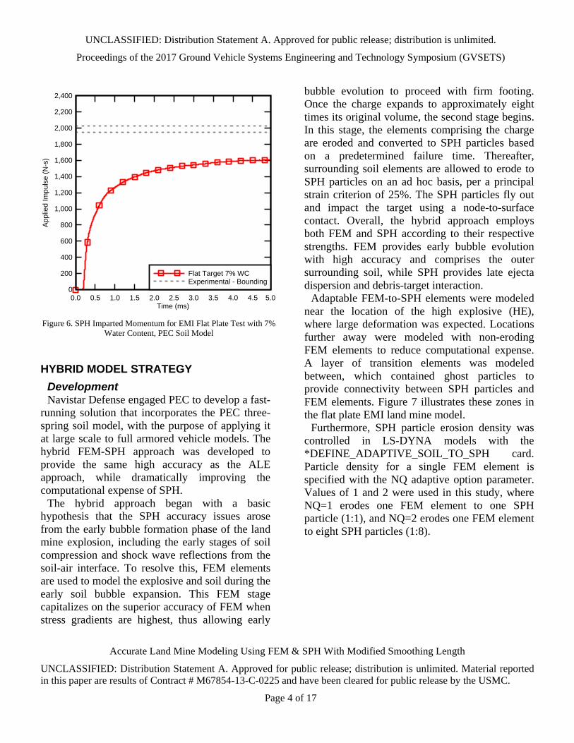
been corrected or not, increasing NQ always seemed to reduce the impulse.
Therefore, the authors suspected that the overall trend was dependent on particle density and its effect on impulse transfer to the target plate.
COEFFICIENT OF RESTITUTION Pingle et al. [9] investigated the impact of a dry
sand column against rigid structures concluding that the impulse transferred is independent of the coefficient of restitution (COR) and friction, but is strongly dependent upon the relative density of the particles in the column. Conceptually, their work verified that sand columns with higher particle density contained more intrinsic impact damping as inbound particles collided with rebound particles.
This concept can be applied to modeling soil cap
impact as well. Coarsely meshed SPH models with fewer particles through the soil cap have less
intrinsic damping between particles than actual sand would have – perhaps just one or two SPH particles through the thickness, as opposed to hundreds of sand particles in actuality. Without this damping, the SPH particles will tend to rebound from the target surface at higher than realistic velocity. As such, the land mine model may be inherently correct, with bubble expansion, gas pressure, and total vertical momentum all represented correctly, and yet the impulse on the target could still be over-predicted due to excess rebound effect.
Contact damping can be used to correct the excess rebound. Coarser meshed models will require more compensatory contact damping. Conversely, finer meshed models, with more particles through the soil cap, will have more intrinsic particle-to-particle impact damping and require less contact damping.
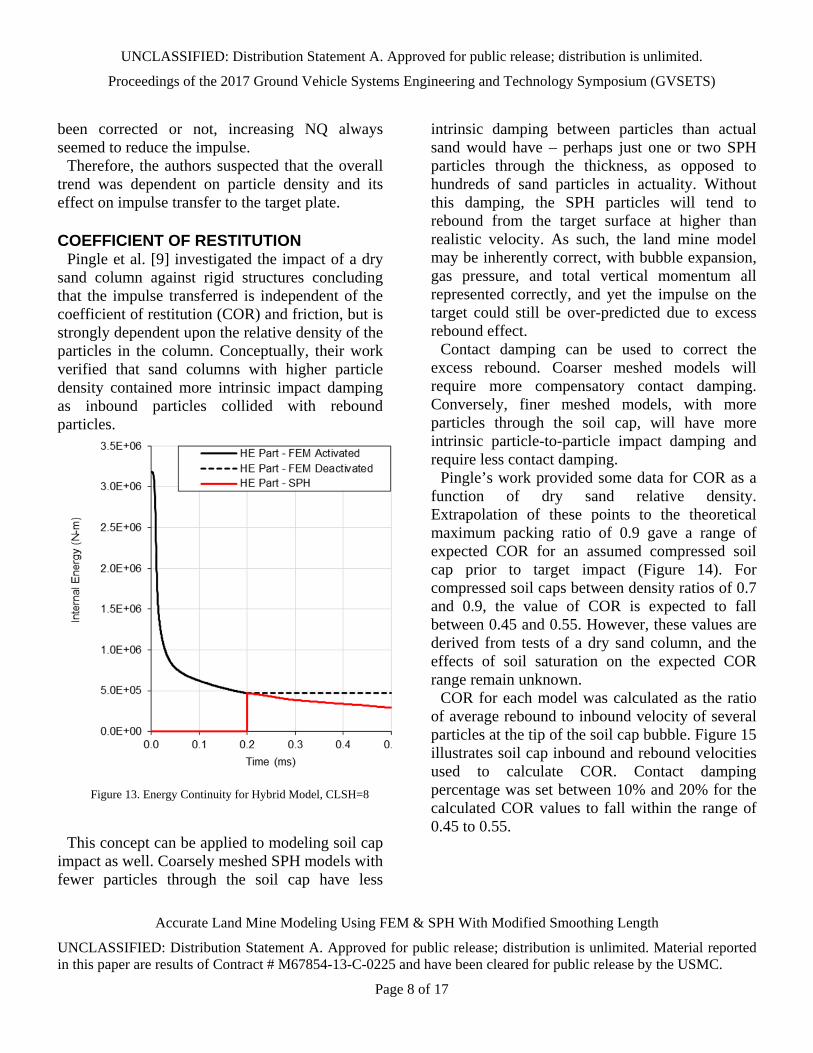
Pingle’s work provided some data for COR as a function of dry sand relative density. Extrapolation of these points to the theoretical maximum packing ratio of 0.9 gave a range of expected COR for an assumed compressed soil cap prior to target impact (Figure 14). For compressed soil caps between density ratios of 0.7 and 0.9, the value of COR is expected to fall between 0.45 and 0.55. However, these values are derived from tests of a dry sand column, and the effects of soil saturation on the expected COR range remain unknown.
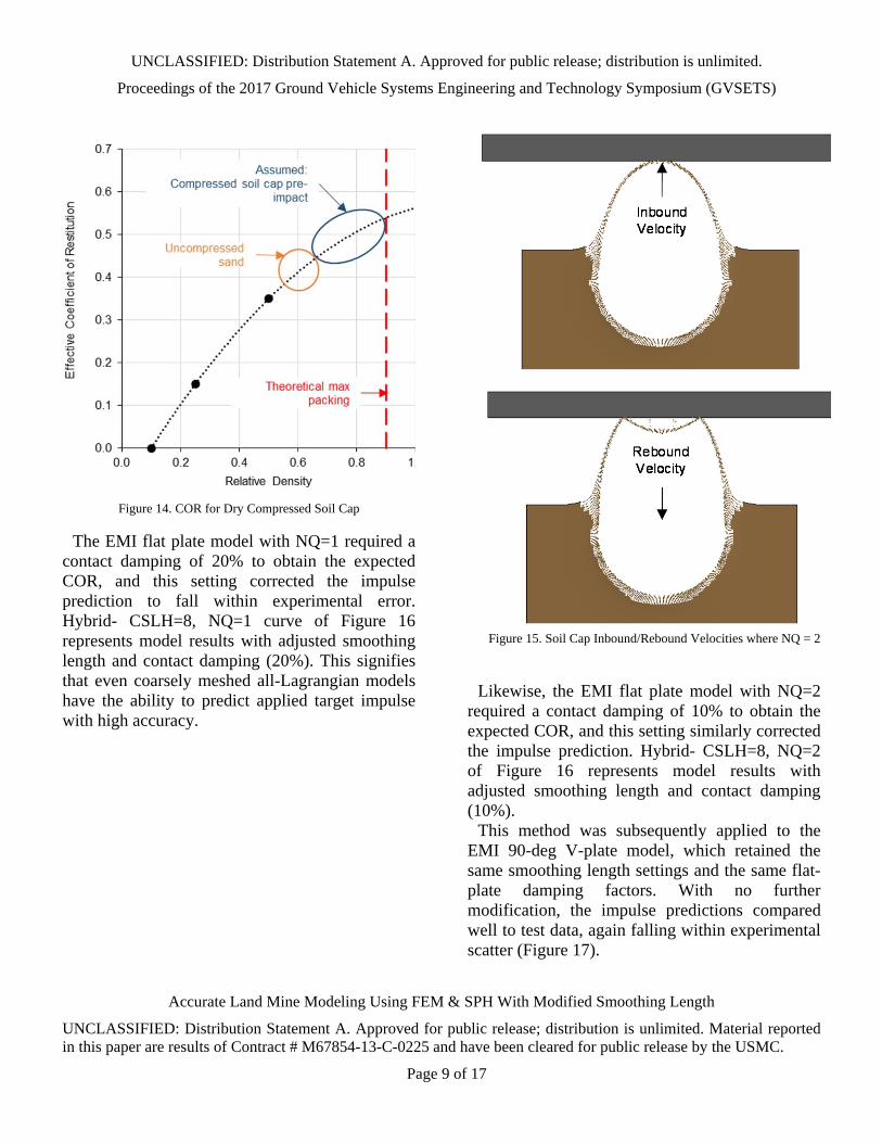
COR for each model was calculated as the ratio of average rebound to inbound velocity of several particles at the tip of the soil cap bubble. Figure 15 illustrates soil cap inbound and rebound velocities used to calculate COR. Contact damping percentage was set between 10% and 20% for the calculated COR values to fall within the range of 0.45 to 0.55.
Figure 13. Energy Continuity for Hybrid Model, CLSH=8
UNCLASSIFIED: Distribution Statement A. Approved for public release; distribution is unlimited.
Proceedings of the 2017 Ground Vehicle Systems Engineering and Technology Symposium (GVSETS)
Accurate Land Mine Modeling Using FEM & SPH With Modified Smoothing Length
UNCLASSIFIED: Distribution Statement A. Approved for public release; distribution is unlimited. Material reported in this paper are results of Contract # M67854-13-C-0225 and have been cleared for public release by the USMC.
Page 9 of 17
The EMI flat plate model with NQ=1 required a
contact damping of 20% to obtain the expected COR, and this setting corrected the impulse prediction to fall within experimental error. Hybrid- CSLH=8, NQ=1 curve of Figure 16 represents model results with adjusted smoothing length and contact damping (20%). This signifies that even coarsely meshed all-Lagrangian models have the ability to predict applied target impulse with high accuracy.
Likewise, the EMI flat plate model with NQ=2
required a contact damping of 10% to obtain the expected COR, and this setting similarly corrected the impulse prediction. Hybrid- CSLH=8, NQ=2 of Figure 16 represents model results with adjusted smoothing length and contact damping (10%).
This method was subsequently applied to the EMI 90-deg V-plate model, which retained the same smoothing length settings and the same flat-plate damping factors. With no further modification, the impulse predictions compared well to test data, again falling within experimental scatter (Figure 17).
Figure 14. COR for Dry Compressed Soil Cap
Figure 15. Soil Cap Inbound/Rebound Velocities where NQ = 2

UNCLASSIFIED: Distribution Statement A. Approved for public release; distribution is unlimited.
Proceedings of the 2017 Ground Vehicle Systems Engineering and Technology Symposium (GVSETS)
Accurate Land Mine Modeling Using FEM & SPH With Modified Smoothing Length
UNCLASSIFIED: Distribution Statement A. Approved for public release; distribution is unlimited. Material reported in this paper are results of Contract # M67854-13-C-0225 and have been cleared for public release by the USMC.
Page 10 of 17
ESSENTIAL FINDINGS To summarize, three essential findings emerged
from this development.
(1) FEM to SPH erosion resolved issues of early bubble formation accuracy that were present with standalone SPH models.
(2) The HE smoothing length correction proved important to ensuring no internal energy losses took place in the explosive during element conversion. This modification preserved the correct “inbound” material momentum.
(3) The coefficient of restitution correction proved important for ensuring that the soil obtained the correct “rebound” momentum, and it was accomplished using mild contact damping. Combined with (1) and (2), this culminated in the correct total applied impulse.
UPSCALING Thus, accurate land mine applied impulse
prediction was accomplished with coarse meshed all-Lagrangian hybrid FEM-SPH models, for both flat and V-plate EMI test cases. However, these cases were subscale. Therefore, it was the desire of the authors to upscale the hybrid model approach to actual vehicle model size.
A large-scale land mine test was selected for modeling from a VIMF test series [8,10], which featured a 10-kg charge in fully saturated sand. Modeling this case required a much larger soil domain, for which various meshing geometries were attempted.
The SPH formulation is characterized as being computationally expensive compared to the FEM approach. To reduce computational expense for full-scale land mine models, it was critical to develop an efficient mesh, with the least amount of SPH particles. An up-scaled 10-m diameter hemispherical butterfly mesh was used to accomplish this (Figure 18).
Figure 16. Flat Plate EMI Impulse Comparison
Time (ms)
App
lied
Impu
lse
(N-s
)
0.0 0.5 1.0 1.5 2.0 2.5 3.0 3.5 40
200
400
600
800
1,000
1,200
1,400
1,600
1,800
2,000
2,200
2,400
ALE - AirSPHHybrid - CSLH=8, NQ=1Hybrid - CSLH=8, NQ=2Experimental - AverageExperimental - Bounding
Figure 17. V-Plate EMI Impulse Comparison
Time (ms)A
pplie
d Im
puls
e (N
-s)
0.0 0.5 1.0 1.5 2.0 2.5 3.0 3.5 4.00
200
400
600
800
1,000
ALE - AirHybrid - CSLH=1.2, NQ=1Hybrid - CSLH=8, NQ=1Hybrid - CSLH=8, NQ=2Experimental - AverageExperimental - Bounding

UNCLASSIFIED: Distribution Statement A. Approved for public release; distribution is unlimited.
Proceedings of the 2017 Ground Vehicle Systems Engineering and Technology Symposium (GVSETS)
Accurate Land Mine Modeling Using FEM & SPH With Modified Smoothing Length
UNCLASSIFIED: Distribution Statement A. Approved for public release; distribution is unlimited. Material reported in this paper are results of Contract # M67854-13-C-0225 and have been cleared for public release by the USMC.
Page 11 of 17
This mesh offers equal element size and spacing
at the core, which translates to equal SPH particle spacing—as recommended for SPH accuracy. Beyond the cubic core, elements efficiently increase in characteristic length until the maximum FEM element size is reached at the peripheral circumference.
Although the cubic core offers equal particle spacing (where the charge is located), the typical transition to a spherical mesh happens within the zone containing soil SPH particles (Figure 19). These transition elements within the SPH zone admittedly violate the recommended equal particle spacing. However, since early bubble formation is accomplished with accurate FEM elements for this hybrid strategy, unequal particle spacing away from the center of explosion was estimated to be
insignificant to the overall accuracy of applied impulse. SPH particle mass steadily increased, and SPH erosion only took place in highly compressed elements.
The full-scale VIMF model was coarsely meshed
with only two elements through the charge thickness and four elements through soil cap thickness. Table 1 compares model statistics between the full-scale hemispherical model and the four previously discussed EMI models.
The full-scale FEM element count was about
three and a half times the amount of the small-scale models. Additionally, the efficient mesh of
Figure 18. Hemispherical Butterfly Mesh for Full-Scale Land Mine Models
Figure 19. Hemispherical Butterfly Mesh Transition
Table 1. Model Statistic Comparison
Metric
EMIFlat PlateNQ=1
EMIFlatPlateNQ=2
EMIV‐
PlateNQ=1
EMIV‐
PlateNQ=2
Hemispherical Mesh
Flat PlateNQ=1
No. FEMElements
212K 212K 209K 209K 700K
No. SPHParticles
122K 975K 122K 975K 388K
Clock Time1 (hrs)
0.4 4.82 0.72 12.02 6.22
No. CPUs 8 16 8 8 16
CPU Hours 3.3 76.82 5.62 96.02 99.02
1Based on a 5‐ms simulation time2Linearly extrapolated to 5‐ms simulation time
UNCLASSIFIED: Distribution Statement A. Approved for public release; distribution is unlimited.
Proceedings of the 2017 Ground Vehicle Systems Engineering and Technology Symposium (GVSETS)
Accurate Land Mine Modeling Using FEM & SPH With Modified Smoothing Length
UNCLASSIFIED: Distribution Statement A. Approved for public release; distribution is unlimited. Material reported in this paper are results of Contract # M67854-13-C-0225 and have been cleared for public release by the USMC.
Page 12 of 17
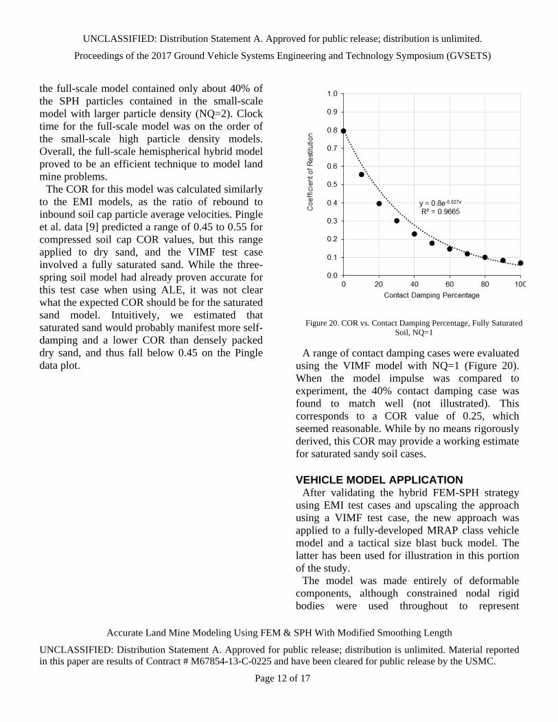
the full-scale model contained only about 40% of the SPH particles contained in the small-scale model with larger particle density (NQ=2). Clock time for the full-scale model was on the order of the small-scale high particle density models. Overall, the full-scale hemispherical hybrid model proved to be an efficient technique to model land mine problems.
The COR for this model was calculated similarly to the EMI models, as the ratio of rebound to inbound soil cap particle average velocities. Pingle et al. data [9] predicted a range of 0.45 to 0.55 for compressed soil cap COR values, but this range applied to dry sand, and the VIMF test case involved a fully saturated sand. While the three-spring soil model had already proven accurate for this test case when using ALE, it was not clear what the expected COR should be for the saturated sand model. Intuitively, we estimated that saturated sand would probably manifest more self-damping and a lower COR than densely packed dry sand, and thus fall below 0.45 on the Pingle data plot.
A range of contact damping cases were evaluated
using the VIMF model with NQ=1 (Figure 20). When the model impulse was compared to experiment, the 40% contact damping case was found to match well (not illustrated). This corresponds to a COR value of 0.25, which seemed reasonable. While by no means rigorously derived, this COR may provide a working estimate for saturated sandy soil cases.
VEHICLE MODEL APPLICATION After validating the hybrid FEM-SPH strategy
using EMI test cases and upscaling the approach using a VIMF test case, the new approach was applied to a fully-developed MRAP class vehicle model and a tactical size blast buck model. The latter has been used for illustration in this portion of the study.
The model was made entirely of deformable components, although constrained nodal rigid bodies were used throughout to represent
Figure 20. COR vs. Contact Damping Percentage, Fully Saturated Soil, NQ=1

UNCLASSIFIED: Distribution Statement A. Approved for public release; distribution is unlimited.
Proceedings of the 2017 Ground Vehicle Systems Engineering and Technology Symposium (GVSETS)
Accurate Land Mine Modeling Using FEM & SPH With Modified Smoothing Length
UNCLASSIFIED: Distribution Statement A. Approved for public release; distribution is unlimited. Material reported in this paper are results of Contract # M67854-13-C-0225 and have been cleared for public release by the USMC.
Page 13 of 17
connectivity. The vehicle model contained roughly 705K elements (Figure 21).
Null Elements (blue), which are used as part of
the hybrid methodology, utilized 18K elements. The soil model was comprised of 823K soil elements, of which 490K were adaptable to SPH. Figure 22 shows a section cut of the blast model at 0-ms (top) and 10-ms (bottom).
The vehicle land mine model was broken into three sequential phases. The first two phases were the same as for the EMI and VIMF test cases: pre- and post-conversion from FEM to SPH. The third phase took place after the soil had reached full velocity and had transited upward a significant distance. At that point, the SPH particles were deactivated, thereby turning them into “dead” nodes that continue their dispersion and interact with the vehicle as simple point masses. This simplification was found to provide reasonable results while reducing computational cost.
Based on the meshing technique utilized, the soil
elements comprising the cubic core were of a regular size (10 mm cubes). Although there are hundreds of thousands of soil particles generated in this simulation, and these particles are relatively small, they were traveling at over 1000 m/s and created point loads on the structural elements during impact.
These point loads produced significant localized deformation, which was not realistic; actual soil is comprised of particulates that are much smaller, more numerous, and more distributed than the 10-mm soil particles. These point loads were better distributed on the vehicle by bonding larger null material elements to the strike face of various components. One null element was used for every four structural elements in this model.
Figure 23 shows a comparison of performance with and without the null shell load distributors. When a null element was struck by a particle, the load from the particle was distributed over all the
Figure 21. Tactical Vehicle and Land Mine Model
Figure 22. Blast Simulation at 0-ms and 10-ms

UNCLASSIFIED: Distribution Statement A. Approved for public release; distribution is unlimited.
Proceedings of the 2017 Ground Vehicle Systems Engineering and Technology Symposium (GVSETS)
Accurate Land Mine Modeling Using FEM & SPH With Modified Smoothing Length
UNCLASSIFIED: Distribution Statement A. Approved for public release; distribution is unlimited. Material reported in this paper are results of Contract # M67854-13-C-0225 and have been cleared for public release by the USMC.
Page 14 of 17
nodes lying beneath the surface of the null element through a tied contact. Localized damage issues were thus resolved with what amounted to a distributed contact methodology.
One clear benefit of the hybrid FEM-SPH
approach is the visual information that it provides in identifying the key factors influencing vehicle blast performance. To demonstrate, additional simplified structure was added to the vehicle model to simulate the effect of underbody components, as illustrated in Figure 24 (top right).
By comparing the initial and post-blast images, it
is clear that the proposed particle method captures the effect of geometry on soil ejecta path and the changing loading conditions it creates. The center cylindrical structure shields the component directly above it, but results in more soil striking the lower panel. The side box structure protects the outboard side of the lower panel, but redirects more soil to the inner side of the lower panel.
The nature of the load change is depicted in the plastic strain contours of the vehicle with and without the additional structure shown in Figure 24 (bottom). The contours illustrate how vehicle geometry can channel the soil and also help determine if the outcome will be desirable or detrimental to overall vehicle blast performance. As a notable advantage over ALE models, the SPH approach does not require a large container domain to allow long-distance material travel,
Figure 23. Strike Face Behavior with and without Null Shell Load
Distributors
Figure 24. Effects of Soil Particles Structural Shielding, before (top) and after (bottom) Blast Loading, with (right) and without
(left) Additional Vehicle Components

UNCLASSIFIED: Distribution Statement A. Approved for public release; distribution is unlimited.
Proceedings of the 2017 Ground Vehicle Systems Engineering and Technology Symposium (GVSETS)
Accurate Land Mine Modeling Using FEM & SPH With Modified Smoothing Length
UNCLASSIFIED: Distribution Statement A. Approved for public release; distribution is unlimited. Material reported in this paper are results of Contract # M67854-13-C-0225 and have been cleared for public release by the USMC.
Page 15 of 17
channeling through narrow crevices in the vehicle structure, etc.
Comparing the changing density of particles striking in a given area between multiple design iterations is a good way to identify where the soil may challenge the vehicle structure. In many instances, it will be readily apparent where structural modification will enhance vehicle blast performance. However, this may not always be obvious, especially if high numbers of particles are used, clouding visibility. When a higher level of granularity is employed, using a post-processor’s tracing function gives a clear indication of particle origins and paths (Figure 25).
Understanding the effect of soil loading on a
vehicle structure is of critical importance for the survivability engineer. A secondary benefit of the hybrid approach is the clarity the user receives in studying the physics of the blast event. The propagation of the soil bubble is well illustrated in the progressive frames shown in Figure 26.
Figure 25. SPH Particle Trace
Figure 26. Soil Cap Velocity Contours

UNCLASSIFIED: Distribution Statement A. Approved for public release; distribution is unlimited.
Proceedings of the 2017 Ground Vehicle Systems Engineering and Technology Symposium (GVSETS)
Accurate Land Mine Modeling Using FEM & SPH With Modified Smoothing Length
UNCLASSIFIED: Distribution Statement A. Approved for public release; distribution is unlimited. Material reported in this paper are results of Contract # M67854-13-C-0225 and have been cleared for public release by the USMC.
Page 16 of 17
The time dependent nature of vehicle loading is revealed as the bubble of soil expands outward. Figure 26 demonstrates that the highest velocity particles are on top of the soil bubble. These particles have the greatest potential to increase loading on localized areas of the vehicle hull through channeling. Additionally, oblique strikes on vertical surfaces from the upper particles will do little to sap the kinetic energy of the soil. The momentum handoff from soil to vehicle is clearly illustrated as the particle velocity transitions from energized red to slow blue as shown in the velocity contour plots in Figure 26.
Model statistics for the Tactical and MRAP Vehicle models employing the hybrid FEM-SPH approach are listed in Table 2.
Examination of the Navistar Defense Tactical Vehicle model using the hybrid FEM-SPH land mine methodology demonstrates the power of particle based blast analysis. It gives the survivability engineer significant insight into the physics of a blast event and becomes a powerful tool in successfully designing vehicles to protect their occupants.
OBSERVATIONS & CONCLUSIONS The SPH smoothing length modification appears
to remedy a fundamental inaccuracy of hybrid land mine modeling, which is supported by two observations. First, the smoothing length change eliminates the sudden loss of internal energy in the explosive material. Second, it resolves the shortfall in applied impulse. While an impulse improvement could potentially arise from various knob-turning, the repair of internal energy conservation would be difficult to explain as happenstance. Our conclusion is that the smoothing length likely is a root cause of SPH discrepancies in land mine models, and that some adjustment to smoothing length is required for a root-level repair.
However, from a theory standpoint the smoothing length adjustment used in this effort is somewhat approximate, and two phenomenology observations suggest that more elegant solutions may be possible. First, the SPH and ALE impulse histories are not identical and do not fully overlay one another. Based upon prior PEC evaluations of various numerical formulations, there are several points of circumstantial evidence to suggest that the ALE loading could be viewed as a baseline for comparison. On this working assumption, the modified SPH implementation shows some room for improved replication. Second, the SPH explosive particles do not appear to be uniformly distributed within the soil cavity at all times, with some gap formation occurring near the soil cavity walls. Non-uniform distribution likely arises from the sharp discontinuities in particle spatial density for the two materials; the soil particles become more tightly packed than the explosive particles at the same pressure. To the authors’ best knowledge, the smoothing length adjustment in this effort remains an essentially isotropic modification, but a dynamic directionally-variable approach may be warranted. The dynamic smoothing length calculation in LS-DYNA could
Table 2. Full-Scale Vehicle Model Statistics
Metric Tactical Vehicle MRAP Vehicle
No. CPUs 6 12
No. Vehicle Deformable Elements 705K 1.7M
No. Null Deformable Elements 18K 8K
No. Soil Deformable Elements 823K 2.7M
No. Total Deformable Elements 1.5M 4.4M
Cubic Core Element Size 10‐mm cube 15‐mm cube
Time Step (s) 5.0E‐07 3.0E‐07
Phase 1 (0.5‐ms) ‐ FEM Soil 0.1‐hours 0.7‐hours
Phase 2 (2.5‐ms) ‐ SPH Conversion 10.0‐hours 40.0‐hours
Phase 3 (7.0‐ms) ‐ SPH Deactivation 6.0‐hours 15.7‐hours
Total Clock Time (10‐ms) 16.1‐hours 56.4‐hours

UNCLASSIFIED: Distribution Statement A. Approved for public release; distribution is unlimited.
Proceedings of the 2017 Ground Vehicle Systems Engineering and Technology Symposium (GVSETS)
Accurate Land Mine Modeling Using FEM & SPH With Modified Smoothing Length
UNCLASSIFIED: Distribution Statement A. Approved for public release; distribution is unlimited. Material reported in this paper are results of Contract # M67854-13-C-0225 and have been cleared for public release by the USMC.
Page 17 of 17
potentially be modified by including the particle spatial density gradient or the pressure gradient.
In its present form, the modified smoothing length strategy provides a reasonable and workable solution. The approach leverages the previously developed PEC three-spring soil model for accurate representation of a range of sandy soil densities and saturation levels. The modified smoothing length conserves the internal explosive energy. Mild contact damping produces a proper coefficient of restitution for coarsely meshed soil caps. The combination of smoothing length and coefficient of restitution produces applied impulses on both flat and V-plate targets that match experimental data. In application to vehicle models, null shells allow the use of larger soil particles while minimizing artificial point load concentrations. Overall, the hybrid SPH strategy provides an approach for modeling landmine loading of vehicles that can include regions and parts well above the nominal undercarriage, while avoiding the need for very large ALE domains or non-constitutive material approaches as used for DEM.
REFERENCES [1] Matt Barsotti, Eric Sammarco, and David Stevens,
"Comparison of Strategies fo Landmine Modeling in LS-DYNA with Sandy Soil Material Model Devlopment," in 14th International LS-DYNA Users Conference, Dearborn, MI, 2016.
[2] David J. Stevens and Matt A. Barsotti, "Modeling of Landmine Loading of Armored Vehicles and Extension to Field Testing Assessment," in 2016 NDIA Ground Vehicle Systems Engineering and Technology Symposium, Novi, MI, 2016.
[3] Matt Barsotti, Eric Sammarco, and David J Stevens, "Mitigation of Blast Injuries Through Modeling and Simulation: Task 1 Report: Soil and Explosive Modeling," Quantico, 2015.
[4] Leo Laine and Andreas Sandvik, "Derivation of Mechanical Properties for Sand," in 4th Asia-Pacific Conference on Shock and Impact Loads on Structures, Singapore, 2001, pp. 361-368.
[5] Gerald I Kerley, "Documentation of Data on Sandia ANEOS Library File," Albuquerque, 2001.
[6] G.I. Kerley, "ARL-CR-461: Numerical Modeling of Buried Mine Explosions," 2001.
[7] Charles E. Anderson, Rory P. Bigger, Thilo Behner, Carl E. Weiss, and Sidney Chocron, "18.12544/011: Mine-Blast Loading: Experiments and Simulations," Southwest Research Institute, Herndon, 18.12544/011, May 24-26, 2010.
[8] R. Reed Skaggs, William Gault, and Leslie C. Taylor, "ARL-TN-250: Vertical Impulse Measurements of Mines Buried in Saturated Sand," Weapons and Materials Research Directorate, Aberdeen Proving Ground, MD, ARL-TN-250, 2006.
[9] S.M. Pingle, N.A. Fleck, H.N.G. Wadley, and V.S. Deshpande, "Discrete element calculations of the impact of a sand column against rigid structures," Int. Journal of Impact Engineering, vol. 45, pp. 74-89, 2012.
[10] M. Grujicic et al., "Impulse Loading Resulting From Shallow Buried Explosives in Water-Saturated Sand," J. Materials: Design and Applications, vol. 221, pp. 21-35, 2007.