accessories - pei-genesis · accessories menu for assistance in europe – please see the back...
TRANSCRIPT

Accessories
Accessories & Side Dishes
Accessories Directory ............................... 213
Flexible Braided Sleeving ...................214-221
Wrap Around Sleeving ......................222-225
Flexible Braided Shielded Sleeving ........... 226
Heat Shrink Tubing ................................. 227
Specialty Heat Shrink Tubing ................... 228
Heat Shrink Transitions ............................ 229
Cord Grips ........................................230-235
Conduit & Adapters ...........................236-242
Potting Compounds ..........................243-245
Tapes ................................................246-247
Terminals & Lugs ...............................248-249
Cable Ties ............................................... 250
Tools .................................................251-253

214
Accesso
riesM
enu D
In North America: Pricing Delivery: 800-642-8750 • Tech Support: 800-523-0727 • www.peigenesis.com • Specifications subject to change.
Flexible Braided SleevingAccesso
ries Flexib
le Braid
ed Sleevin
g
Physical Properties PTN FRN CCF HWN NHN Monofilament Diameter ASTM D-204 .010 .010 .008 .015 NA Flammability Rating FAR 25, FMVSS 302 VW-1, FAR 25 VW-1 - - Recommended Cutting Hot Knife Hot Knife Scissor Hot Knife Hot Knife Stock Colors 19 2 2 3 1 Wall Thickness .025 .025 .024 .038 - Tensile Strength PSI ASTM D-2256 85,000 55,000 55,000 85,000 55,000 Abrasion Resistance ASTM D-4157 High High High Very High Very High Tenacity (Gm/Denier) ASTM D-638 4.5 4.6 4.6 4.5 - Specific Gravity ASTM D-792 1.38 1.38 1.38 1.38 1.12 Moisture Absorption % ASTM D-570 .08 .08 .08 .08 1.1 Smoke D-Max ASTM E-662 56 275 275 56 - Toxicity Index USN 713 4.2 6.2 6.2 4.2 - Typical Elongation ASTM D-2256-8 Break 15 15 14 20 - 3g/Denier 5 5 5 7 - Hard Vacuum Data ASTM E-595 at 10-5 torr TML .51 .19 .19 .51 - CVCM 0 .01 .01 0 - WVR .10 .11 .11 .10 - Operating Temperatures Minimum Continuous -75°C/-103°F -75°C/-103°F -75°C/-103°F -75°C/-103°F -45°C/-49°F Maximum Continuous Mil-l-23053 125°C/257°F 125°C/257°F 125°C/257°F 125°C/257°F 150°C/302°F Melt ASTM D-2117 230°C/446°F 250°C/482°F 250°C/482°F 230°C/446°F 265°C/509°F Chemical Resistance 1=No Effect 2-Little Effect 3=Affected 4=More Affected 5=Severely Affected Aromatic Solvents 2 2 2 2 1 Aliphatic Solvents 1 1 1 1 1 Chlorinated Solvents 3 3 3 3 1 Weak Bases 1 1 1 1 1 Salts 1 1 1 1 1 Strong Bases 2 2 2 2 2 Salt Water O-S 1926 1 1 1 1 1 Hydraulic Fluid MIL-A-8243 1 1 1 1 1 Lube Oil MIL-L-7808 1 1 1 1 1 De-Icing Fluid MIL-A-8243 1 1 1 1 1 Strong Acids 3 3 3 3 5 Strong Oxidants 2 2 2 2 5 Esters/Keytones 1 2 2 1 - UV Light 1 1 1 1 - Petroleum 1 1 1 1 2 Fungus ASTM G-21 1 1 1 1 2 Outgassing med med med med high Oxygen Index ASTM D-2863 21 31 31 21 22 Halogen Free yes yes yes yes -
Technical Specifications

215
Accesso
riesM
enu D
For Assistance in Europe – Please See the Back Cover For a Complete Listing of Our Branch Offices and Contact Numbers. • Specifications subject to change.
Accesso
riesFlexib
le Braid
ed Sleevin
g
FWF RYN KVN NXN TFN PEEK HTN PG01-19-001 MBN .10 .008 NA N/A .016 .010 .011 0.01 - VW-1 FAR 25 - - FAR 25 V-0 UL94 VW-1, UL94 VW-1, UL94 - Hot Knife Hot Knife Kevlar Shears Scissor Hot Knife Hot Knife Hot Knife Kevlar Shears Scissor 1 2 1 1 1 1 2 1 1 .025 .02 .020 - .04 .025 .02 - - 55,000 - 439,000 90,000 20,000 - 45,000 - - High Med Very High High Med High Med Very High Very High 4.6 - 23.8 4.9 1 - 2 - - 1.38 1.37 1.44 1.38 2.10 1.32 1.68 - - .08 .02 - - <.01 - .01 - - 275 - - - - - - - - 6.2 - - - - - - - - 15 30 2.5 27 - - - - - 5 - - - - - - - - .19 - - - - - - - - .01 - - - - - - - - .11 - - - - - - - - -75°C/-103°F -70°C/-94°F -170°C/-340°F -196°C/-320°F -70°C/-94°F -70°C/-94°F -75°C/-103°F -40°C/-40°F - 125°C/257°F 200°C/392°F 160°C/320°F 350°C/662°F 280°C/550°F 260°C/500°F 150°C/302°F 150°C/302°F - 250°C/482°F 285°C/545°F NA NA 310°C/590°F 340°C/644°F 240°C/464°F n/a - 2 - 2 - 1 1 1 2 - 1 1 2 - 1 1 1 2 - 3 - 2 - 1 1 1 2 - 1 1 1 - 1 1 1 1 - 1 1 1 - 1 1 1 1 - 2 - 2 1 1 1 1 2 - 1 1 1 - 1 1 1 1 - 1 1 1 - 1 1 1 1 - 1 1 1 - 1 1 1 1 - 1 1 1 - 1 1 1 1 - 3 - 2 2 1 2 1 2 - 2 - 2 2 1 - 1 2 - 2 1 1 - 2 - 2 1 1 1 1 4 3 1 - 1 4 2 1 1 1 1 1 1 1 1 - 1 1 2 - 1 - 1 2 - med low - - very low low low - - 31 40 29 28 95 35 64 - - yes yes yes yes no yes no yes yes
Flexible Braided Sleeving
FLEX-SHIELD HP

216
Accesso
riesM
enu D
In North America: Pricing Delivery: 800-642-8750 • Tech Support: 800-523-0727 • www.peigenesis.com • Specifications subject to change.
A Versatile Bundling & Protection Solution
•Economical&easy to install
•Cut&abrasionresistant
•Expandsupto150%
•Halogenfree
•Resistsgasoline, engine chemicals & cleaning solvents
•FAR25approval
•AFVSS302approval
50%ThickerForTheReally Abrasive Jobs
•Braidedfrom.15mil PET monofilament
•Extremeabrasion& cut resistance
•UVresistant
•Resistsgasoline,solvents, salt water and chemicals
•Temp.range-75°Cto125°C
•Melttemp.230°C
Innovative Flat Filament Braided for High
Abrasion Resistance
•Flatfilamenttechnology
•Heavyplasticprotection
•Smoothfeel& reduced drag
Flame Retardant, Economical Sleeving
Solution
•MIL-202,FAR25,FMVSS 302, VW-1, FR-1 approved
•Economical&easy to install
•Cut&abrasionresistant
•Expandsupto150%
•Halogenfree
•Resistsgasolineandengine chemicals
•Temp.range-75°Cto125°C
•Melttemp.250°C
Scissor Cut for Field Installation, Will Not Support Combustion
•Scissorcutforeasy installation
•MIL-202,FAR25,VW-1, FR-1 approved
•Cut&abrasionresistant
•Expandsforeaseof installation
•Halogenfree
•Temp.range-75°Cto125°C
•Melttemp.250°C
Easy On, Easy Off Access, Will Not
Support Combustion
•MIL-202,VW-1, FR-1 approved
•Economical&easyto install
•Cut&abrasionresistant
•Hook&loopclosurefor easy and repeatable access
•Temp.range-75°Cto125°C
•Melttemp.250°C
PTN
HWN NHN
FRN CCF
FWF
Flexible Braided SleevingAccesso
riesFlexib
le Braid
ed Sleevin
g

217
Accesso
riesM
enu D
For Assistance in Europe – Please See the Back Cover For a Complete Listing of Our Branch Offices and Contact Numbers. • Specifications subject to change.
Very Low Outgassing, Self-Extinguishing UL-2024
Plenum Rated Sleeving
• UL 2024 rated• FAR 25 approved• Cut & abrasion resistant• Expands up to 150%• Resists gasoline and engine chemicals• Temp. range -75°C to 150°C• Melt temp. 250°C
Stronger Than Steel, Soft & Pliable
• Up to 20 times stronger than steel• Will not melt, burn or support combustion• Stays soft, flexible and pliable through- out -170°C operating temperature range
500°F Protection & Bundling Solution
• High chemical resistance• Low outgassing• Halogen free• Very light weight• V-O flammability rating• Wear resistant• High strength alternative to fluropolymers
Ultra Lightweight, High-Temp Tolerant and Virtually Impervious to Chemical Degradation
•FAR25approved
•Ultralightweight
•Highlywearresistant
•Expandsupto150%
•Resistsacids,bases, solvents, fuels
•Temp.range-70°Cto200°C
•Melttemp.285°C
High Temp Stable, Abrasion Resistant, Low Outgassing
• Plenum suitable• FAR 25 approved• Easy to install• Cut & abrasion resistant• Expands up to 150%• Resists gasoline and other chemicals• Temp. range -70°C to 280°C• Melt temp. 310°C
KVN
Soft, Pliable Flame Protection to 700°F/395°C
• Halogen free• Asbestos free• Resistant to gasoline and engine chemicals
NXN
PEEK
RYN
Tin-Plated, Copper-Wrapped Aramid Sleeve
• Lightweight alternative to metal braid for EMI/RFI protection• -40°C to 150°C
PG01-19-001*
TFN
High Temp Stable, Abrasion Resistant, Low Outgassing
• EMI/RFI/ESD protection
• Supplied on tube former for easy installation
FLEXA HG-CU
Metal Braid, Tinned-Copper Sleeve
•EMI/RFI/ESDprotection
•Grounding/groundingstraps
•Highcurrentcapacity
•ASTM-B33standard
•Lowcost
MBN
HTN
Accesso
riesFlexib
le Braid
ed Sleevin
g
FLEX-SHIELD-HP
Frequency Attenuation (MHz) (dB) 1 50 10 63 50 64 100 65 500 73 1000 60
*Size Diameter Min(inches) Max(inches) 1/8 1/16 1/4 3/8 1/4 1/2 1/2 3/8 3/4 3/4 1/2 1
Call for low cost version: -15°C/+85°C
Special VersionsCall for availability

218
Accesso
riesM
enu D
In North America: Pricing Delivery: 800-642-8750 • Tech Support: 800-523-0727 • www.peigenesis.com • Specifications subject to change.
Flexible Braided Sleeving for Cable Diameters .094-1.625Accesso
riesFlexib
le Braid
ed Sleevin
g, C
able D
ia: .094-1
.625
Colors Available ** Add code to part number
Cable Range Inch
Part Number min max
PTN0.13** 0.094 0.250 NR NP NY NG NB BE CB NX PT
FRN0.13** 0.094 0.250 TW TB
HTN0.13** 0.094 0.250 TW TB
RYN0.13** 0.094 0.250
TFN0.13** 0.094 0.250
CCF0.13** 0.125 0.250 TW TB
KVN0.25** 0.125 0.313
RYN0.25** 0.125 0.375
PTN0.25** 0.125 0.438 NR NP NY NG NB BE CB NX PT
FRN0.25** 0.125 0.438 TW TB
CCN0.25** 0.125 0.438
HTN0.25** 0.125 0.438 TW TB
CCF0.25** 0.156 0.438 TW TB
TFN0.25** 0.188 0.375
PTN0.38** 0.188 0.625 NR NP NY NG NB BE CB NX PT
FRN0.38** 0.188 0.625 TW TB
CCF0.38** 0.188 0.625 TW TB
CCN0.38** 0.188 0.625
HTN0.38** 0.188 0.625 TW TB
HWN0.38** 0.188 0.750 CB
KVN0.50** 0.250 0.625
PTN0.50** 0.250 0.750 NR NP NY NG NB BE CB NX PT
FRN0.50** 0.250 0.750 TW TB
CCF0.50** 0.250 0.750 TW TB
CCN0.50** 0.250 0.750
HTN0.50** 0.250 0.750 TW TB
RYN0.50** 0.250 0.750
TFN0.38** 0.250 0.750
HWN0.63** 0.313 1.000 CB
NHN0.50** 0.375 0.625
TFN0.50** 0.375 0.875
PTN0.63** 0.375 1.000 NR NP NY NG NB BE CB NX PT
FRN0.75** 0.375 1.000 TW TB
KVN0.75** 0.500 0.875
PTN0.75** 0.500 1.250 NR NP NY NG NB BE CB NX PT
CCN0.75** 0.500 1.250
HTN0.75** 0.500 1.250 TW TB
RYN0.75** 0.500 1.250
HWN1.00** 0.500 1.500 CB
CCF0.75** 0.625 1.000 TW TB
NHN0.75** 0.625 1.000
TFN0.75** 0.625 1.250
PTN1.00** 0.625 1.625 NR NP NY NG NB BE CB NX PT
FRN1.50** 0.625 1.625 TW TB
CCN1.00** 0.625 1.625
Cable Range and Colors
BOLD = Most Popular

219
Accesso
riesM
enu D
For Assistance in Europe – Please See the Back Cover For a Complete Listing of Our Branch Offices and Contact Numbers. • Specifications subject to change.
Accesso
riesFlexib
le Braid
ed Sleevin
g
Colors Available** Add code to part number
RD OR YL GN BL PP CL BK WH GY
BK NT
NT
YL
BK NT
RD OR YL GN BL PP CL BK WH GY
BK
NT
RD OR YL GN BL PP CL BK WH GY
BK
CL BK
YL
RD OR YL GN BL PP CL BK WH GY
BK
BK NT
NT
CL BK
BK
NT
RD OR YL GN BL PP CL BK WH GY
YL
RD OR YL GN BL PP CL BK WH GY
BK
BK NT
CL BK
BK
NT
RD OR YL GN BL PP CL BK WH GY
BK
Flexible Braided Sleeving

220
Accesso
riesM
enu D
In North America: Pricing Delivery: 800-642-8750 • Tech Support: 800-523-0727 • www.peigenesis.com • Specifications subject to change.
Flexible Braided Sleeving for Cable Diameters .750-5.500Accesso
riesFlexib
le Braid
ed Sleevin
g, C
able D
ia: .750-.5
00
Colors Available ** Add code to part number
Cable Range Inch
Part Number Min. Max.
CCF1.00** 0.750 1.188 TB TW
KVN1.00** 0.750 1.250
PTN1.25** 0.750 1.750 NR NP NY NG NB BE CB NX PT
FRN1.75** 0.750 1.750 TW TB
HTN1.25** 0.750 1.750 TW TB
RYN1.25** 0.750 1.750
HWN1.50** 0.750 2.000 CB
CCF1.25** 1.000 1.500 TW TB
NHN1.25** 1.000 1.500
KVN1.25** 1.000 1.625
PTN1.50** 1.000 2.500 NR NP NY NG NB BE CB NX PT
FRN1.50** 1.000 2.500 TW TB
TFN1.25** 1.125 1.500
CCF1.50** 1.250 2.000 TW TB
KVN1.50** 1.250 2.000
PTN1.75** 1.250 2.750 NR NP NY NG NB BE CB NX PT
FRN1.75** 1.250 2.750 TW TB
HTN1.75** 1.250 2.750 TW TB
RYN1.75** 1.250 5.500
NHN1.75** 1.500 2.000
HWN2.00** 1.500 3.000 CB
PTN2.00** 1.500 3.500 NR NP NY NG NB BE CB NX PT
FRN2.00** 1.500 3.500 TW TB
HTN2.00** 1.500 3.500 TW TB
PTN2.50** 1.750 4.500 NR NP NY NG NB BE CB NX PT
FRN2.50** 1.750 4.500 TW TB
HWN3.00** 2.000 4.000 CB
PTN3.00** 2.500 4.750 NR NP NY NG NB BE CB NX PT
FRN3.00** 2.500 4.750 TW TB
HWN4.00** 2.500 5.500 CB
Handheld Hot Knife Bench Mount Hot KnifePerfect for individual projects or small volume production. The large knife blade heats quickly and easily cuts and seals most grades of braided sleeving. Handle can also be used as
a soldering gun with the appropriate tips. 110 volt operation.
Hand Held Hot Knife - Part # HKH0.00BKReplacement Knife Blade - Part # RBH0.00BK
Heavy duty components and heavy gauge 2 1/2” blade make this tool ideal for use in pro-duction environments. Lighted power switch. Heats to 600° C in 30 seconds.
110 volt operation.
Bench Mount Hot Knife - HKB0.00WH
Replacement Knife Blade - RBB0.00BK
BOLD = Most Popular

221
Accesso
riesM
enu D
For Assistance in Europe – Please See the Back Cover For a Complete Listing of Our Branch Offices and Contact Numbers. • Specifications subject to change.
Flexible B
raided
Sleeving
Colors Available** Add code to part number
YL
RD OR YL GN BL PP CL BK WH GY
BK NT
CL BK
BK
YL
RD OR YL GN BL PP CL BK WH GY
NT
YL
RD OR YL GN BL PP CL BK WH GY
BK NT
BK
CL BK
RD OR YL GN BL PP CL BK WH GY
RD OR YL GN BL PP CL BK WH GY
CL BK
RD OR YL GN BL PP CL BK WH GY
CL BK
Flexible Braided Sleeving
#94907K – Handheld Soldering Iron/Hot Knife Kit• Automatic ignition systems• Butane powered• Ergonomic design Specifications:Approx. temperatures:Soldering tip: 210-400°C (410-750°F)Torch: 1300°C (2400°F)Gas container capacity: 20mlOperating time for one gas filling: 120 min. at mid-setting.
Hot Knife
Soldering
Blow Torch
Heat Blow
Deflector
25W-80W Power Range• Multi-function heat tool
Accesso
ries

222
Accesso
riesM
enu D
In North America: Pricing Delivery: 800-642-8750 • Tech Support: 800-523-0727 • www.peigenesis.com • Specifications subject to change.
Wrap Around SleevingAccesso
riesW
rap A
roun
d Sleevin
g
UNSHIELDED Quick-Zip – PVC Coated Polyester Fabric with Zip-Track
Flame retardant PVC is laminated to both sides of a Polyester fab-ric to make this rugged jacket extremely flexible and lightweight. This reinforced construction provides good wear resistance combined with high tear strength. It’s ideal for discrete wires, wire harnesses, hoses, and other applications where its flexibility, strength and abrasion protection are needed. The jacket conforms to MIL-C-43006E, Type II, Class 1.
Application NotesQuick-Zip is easy to open and close. Once closed it is very rugged and reliable. It is a great choice for applications where re-entry is needed to access wires.
UNSHIELDED Quick-Zip Operating Temperature: -20°C to 100°C
Standard Color: Black
Standard Put-up: Spools
Materials: PVC laminated to Polyester fabric
Shielding: –
Flame Rating: UL 224 VW-1
Fastener: Zip-Track
RoHS: Compliant
Properties
SHIELDED Shield-Zip – Shielded PVC Coated Polyester Fabric with Zip-Track
Designed to meet the demand for a quality jacket with lifetime flexibility in most installations, the 63-10 jacket is manufactured of .010” thick high-temperature PVC materials. Inside overlap construction for military applications meets Mil-I-631D, Type F, Form S, Grade C, Class 1. Recognized under the components programs of Underwriters Laboratories, Inc., and Canadian Standards Laboratories. This lightweight shielding is combined with a jacket for economy and flexibility, yet provides protective shielding. Grounding is accomplished with a tinned-copper braid.
Application NotesShield-Zip is easy to open and close. It provides excellent shielding at high frequencies. This is a great option for wire assemblies and bundles that need additional shielding, or for complex assemblies with multiple break-outs. The braid can be separated from the jacket for easy connection with a lug or ring terminal.
UNSHIELDED Maximum Bundle Quick-Zip Diameter Part #:100 Foot Spool
1/2 Inch (12.7 mm) PG99-16-064-0.5
3/4 Inch (19.0 mm) PG99-16-064-0.75
1.0 Inch (25.4 mm) PG99-16-064-1.0
1 1/2 Inch (38.1 mm) PG99-16-064-1.5
2.0 Inch (50.8 mm) PG99-16-064-2.0
Part Numbers
SHIELDED Shield-Zip Operating Temperature: -20°C to 100°C
Standard Color: Black
Standard Put-up: Spools
Materials: PVC laminated to Polyester fabric
Shielding: Aluminum Foil Shield
with Tinned Copper Braid
Flame Rating: UL 224 VW-1
Fastener: Zip-Track
RoHS: –
Shield Attenuation: >85 dB from 10 MHz thru 20 GHz
Enclosure Tool: ZTZ-SP
SHIELDED Maximum Bundle Shield-Zip Diameter Part #:100 Foot Spool
1/2 Inch (12.7 mm) PG97-17-004-0.5
3/4 Inch (19.0 mm) PG97-17-004-0.75
1.0 Inch (25.4 mm) PG97-17-004-1.0
1 1/2 Inch (38.1 mm) PG97-17-004-1.5
2.0 Inch (50.8 mm) PG97-17-004-2.0
Properties
Part Numbers
Wrap Around Zip Closure Re-enterable Wire & Cable Protection
Recommended For:Complex Assemblies: Wrap around sleeving is a great option for complicated cable assemblies. It will fit around a wide range of wires, cables, hoses and bundles. With wrap around materials users do not need to pre-cut and slide tubing over wire bundles before adding connectors or break outs. Instead, the wire harness can be assembled and tested first, and the wrap around sleeve can be added later.
Re-Entry: The Quick-Zip and Shield-Zip versions can be opened and closed over and over again. They make it easy to add or remove wires, repair damaged wires, or adjust cable assembly lengths.
Field Repair and Adjustments: Wrap around protection is an easy and effective way to repair damaged cables or add extra protection to existing cables.

223
Accesso
riesM
enu D
For Assistance in Europe – Please See the Back Cover For a Complete Listing of Our Branch Offices and Contact Numbers. • Specifications subject to change.
Wrap Around Sleeving Accesso
riesW
rap A
roun
d Sleevin
g
SHIELDED & UNSHIELDED Assembly Instructions
1. Lay wires and cables in wrap around sleeving. (Shielded version shown)
2. Slightly open ZTZ-SP hand tool.
3. Slide into Zip tool. 4. Insert opposite side of track into tip of tool. Make sure the tracks mate into each other.
5. Carefully pull tool along sleeving until closed. 6. Slide completely down length of sleeve.
To Re-enter for Repair or Rework
Use ZTZ-SP to disengage zip-track. Separate and slide tool up entire length to open.
This corner into tool
Tool slightly open
Track

224
Accesso
riesM
enu D
In North America: Pricing Delivery: 800-642-8750 • Tech Support: 800-523-0727 • www.peigenesis.com • Specifications subject to change.
Wrap Around Adhesive Closure Wire & Cable Protection
Recommended For:
Complex Assemblies: Wrap around sleeving is a great option for complicated cable assemblies. It will fit around a wide range of wires, cables, hoses and bundles. With wrap around materials users do not need to pre-cut and slide tubing over wire bundles before adding connectors or break outs. Instead, the wire harness can be assembled and tested first, and the wrap around sleeve can be added later.
Field Repair and Adjustments: Wrap around protection is an easy and effective way to repair damaged cables or add extra protection to existing cables.
Wrap Around SleevingAccesso
riesW
rap A
roun
d Sleevin
g
UNSHIELDED Quick-Wrap – PVC Coated Polyester Fabric with Adhesive
Flame retardant PVC is laminated to both sides of a Polyester fab-ric to make this rugged jacket extremely flexible and lightweight. A strip of high strength fast curing (24hrs) acrylic adhesive is bonded to one edge to provide a secure and flexible closure. This reinforced construction provides good wear resistance combined with high tear strength. It’s ideal for discrete wires, wire harnesses, hoses, and other applications where its flexibility, strength and abrasion protection are needed. The jacket conforms to MIL-C-43006E, Type II, Class 1.
Application NotesQuick-Wrap is quick and easy to install. It is a great alternative to long runs of heat shrink, especially for complex cables with lots of break- outs or for assemblies with an unusual mix of wires, cables and/or hoses. It can be added after the wire assembly has been built and tested or to add extra protection on an existing assembly.
UNSHIELDED Quick-Wrap Operating Temperature: -20°C to 100°C
Standard Color: Black
Standard Put-up: Spools
Materials: PVC laminated to Polyester fabric
Shielding: –
Flame Rating: UL 224 VW-1
Fastener: Adhesive
RoHS: Compliant
Properties
SHIELDED Shield-Wrap – Shielded PVC Coated Polyester Fabric with Adhesive
Z-Shield-AL is a combination of a polyurethane film bonded to our SH1 lightweight aluminum foil/polyester shield for maximum shielding effectiveness. Extremely useful in electri-cal applications where shielding is needed and reentry is not required. Ideal for flat cable shielding requirements. Will cross reference to Chomerics CJ-021 Jacket.
Application NotesShield-Wrap is easy to add to wire harnesses and bundles – especially complex assemblies with multiple break-outs. It has excellent shielding properties across a wide range of high frequencies. This makes it a great option to solve unexpected EMI noise problems or to add extra noise protection.
UNSHIELDED Maximum Bundle Quick-Wrap Diameter Part #:100 Foot Spool
1/2 Inch (12.7 mm) PG93-04-009-0.5
3/4 Inch (19.0 mm) PG93-04-009-0.75
1.0 Inch (25.4 mm) PG93-04-009-1.0
1 1/2 Inch (38.1 mm) PG93-04-009-1.5
2.0 Inch (50.8 mm) PG93-04-009-2.0
Part Numbers
SHIELDED Shield-Wrap Operating Temperature: -20°C to 100°C
Standard Color: Black
Standard Put-up: Spools
Materials: PVC laminated to Polyester fabric
Shielding: Aluminum Foil Shield
with Tinned Copper Braid
Flame Rating: UL 224 VW-1
Fastener: Adhesive
RoHS: –
Shield Attenuation: >85 dB from 10 MHz thru 20 GHz
Enclosure Tool: Z Track Enclosure
SHIELDED Maximum Bundle Shield-Wrap Diameter Part #:100 Foot Spool
1/2 Inch (12.7 mm) PG94-04-003-0.5
3/4 Inch (19.0 mm) PG94-04-003-0.75
1.0 Inch (25.4 mm) PG94-04-003-1.0
1 1/2 Inch (38.1 mm) PG94-04-003-1.5
2.0 Inch (50.8 mm) PG94-04-003-2.0
Properties
Part Numbers

225
Accesso
riesM
enu D
For Assistance in Europe – Please See the Back Cover For a Complete Listing of Our Branch Offices and Contact Numbers. • Specifications subject to change.
Wrap Around Sleeving Accesso
riesW
rap A
roun
d Sleevin
g
UNSHIELDED Quick-Wrap Assembly Instructions
1. Identify SHIELDED (inside) and environmentally protected
(outside). Note position of adhesive strip.
3. Fold over the side without the adhesive strip line.
4. Remove the non-stick liner and stick adhesive to outside
of black tube.2. Lay wire and cables on shielded side.
Adhesive Strip Line
5. Continue to remove non-stick lining
until complete. Incorrect Adhesive Termination
Correct Adhesive Termination
Adhesive
AdhesiveOuter Black Tube
Shiny Foil Shield
SHIELDED Quick-Wrap Assembly Instructions
1. Lay wire and/or cables on Quick-Wrap.
3. Start to remove non-stick liner.2. Fold over adhesive closure side of sleeving.
Adhesive Strip
5. Fold over other side of sleeving onto adhesive strip. Pull liner out
a few inches at a time while pressing the sleeving closed. Work up the
assembly until complete. Complete protection in place.
Adhesive Closure

226
Accesso
riesM
enu D
In North America: Pricing Delivery: 800-642-8750 • Tech Support: 800-523-0727 • www.peigenesis.com • Specifications subject to change.
Flexible Braided Shielded SleevingAccesso
riesFlexib
le Braid
ed Sh
ielded
Sleeving
EMI/RFI - EMC Braid Flexa HG-CU Flexible Tinned Copper Braid This braided shield (Screen) is woven over a flexible PVC tube. The tube maintains the shielding shape for excellent shielding performance and simplifies installation. Just attach your wires/cables to the end and pull the tube out from the braid.
1MHz 10MHz 50MHz 100MHz 500MHz 1GHz
Frequency
Att
enu
atio
n in
dB
’s
80
70
60
50
40
30
20
10
0
Flex Shield – Shielding Effectiveness
Frequency Attenuation dB 1MHZ 50 10MHz 63 50MHz 64 100MHz 65 500MHz 73 1GHz 60
Performance
Part Trade Cable Range inch (mm) Cross Section Weight (kg/m) +/-10% Number Size min max Stranding mm2 Pounds Per Foot 4051.701.008 07 (2.5) (10.0) 24x5x0.20mm2 3.0 (0.070) 0.098 0.394 0.047 4051.701.013 10 (5.0) (16.0) 24x6x0.20mm2 4.5 (0.930) 0.197 0.630 0.625 4051.701.017 15 (12.0) (22.0) 24x8x0.20mm2 6.0 (0.109) 0.472 0.866 0.073 4051.701.025 20 (16.0) (27.0) 36x6x0.24mm2 8.7 (0.196) 0.630 1.063 0.132 4051.701.040 25 (20.0) (35.0) 48x7x0.24mm2 11.6 (0.336) 0.787 1.378 0.226 4051.701.055 35 (25.0) (45.0) 48x8x0.24mm2 14.5 (0.370) 0.984 1.772 0.249
High Performance Flex ShieldHigh temperature, ultra light-weight, tinned copper foil-wrapped Aramid Monofilaments braided shield (Screen). This shield works in temperatures from -40°C to 150°C (-40°F to 302°F) and is extremely strong and flexible.
Cable Range inch (mm) Weight (kg/m) +/-10% Part Number min max Pounds Per Foot PG01-19-001-1/8 (1.6) (6.4) (0.012) 0.063 0.250 0.008 PG01-19-001-3/8 (6.4) (12.7) (0.021) 0.250 0.500 0.014 PG01-19-001-1/2 (9.5) (19.1) (0.031) 0.375 0.750 0.021 PG01-19-001-3/4 (12.7) (25.4) (0.042) 0.500 1.000 0.028
How to Pull ThroughTape wires/cables to be pulled and insert into end of PVC tube.
Use electrical or silicone tape to secure wires/cables to PVC tube.
Push the braided shield while pulling PVC tube and wires/cables through.
After PVC tube comes free of the braided shield, un-tape the wires/cables.
Wires/cables are now ready to be un-taped and terminated. 0 100KHz
100MHz
1MHz
120
110
100
90
80
70
60
50
40
30
20
10
0
10MHz 100MHz
FREQUENCY
FREQUENCY
AT
TE
NU
AT
ION
(d
B)
Shielding EffectivenessShielding Effectiveness

227
Accesso
riesM
enu D
For Assistance in Europe – Please See the Back Cover For a Complete Listing of Our Branch Offices and Contact Numbers. • Specifications subject to change.
Heat Shrink Tubing Accesso
riesH
eat Shrin
k Tubin
g
DSG-Canusa’s Heat Shrink Tubing is supplied in various shrink ratios, materials and thickness. Available in several colors with a wide range of operating temperatures; most are flame retardant. Adhesive lined version forms a bond to the underlying surface, filling small voids. When cool this creates a barrier against water, moisture, dirt and other contaminants. Custom lengths are available. Call for ordering information.
CPX100 Heat Shrink Inches (2:1 Ratio) Max. Min.
CPX100-0047-BLK 3/64” 0.047 0.023
CPX100-0063-BLK 1/16” 0.063 0.031
CPX100-0094-BLK 3/32” 0.094 0.047
CPX100-0125-BLK 1/8” 0.125 0.063
CPX100-0187-BLK 3/16” 0.188 0.094
CPX100-0250-BLK 1/4” 0.250 0.125
CPX100-0312-BLK 5/16” 0.313 0.188
CPX100-0375-BLK 3/8” 0.375 0.250
CPX100-0500-BLK 1/2” 0.500 0.313
CPX100-0750-BLK 3/4” 0.750 0.375
CPX100-1000-BLK 1” 1.000 0.500
CPX100-1250-BLK 1 1/4” 1.250 0.625
CPX100-1500-BLK 1 1/2” 1.500 0.750
CPX100-2000-BLK 2” 2.00 1.000
CPX100-3000-BLK 3” 3.00 1.500
CPX100-4000-BLK 4” 4.00 2.000
CPA100 Heat Shrink (3:1 Ratio) Max. Min.
CPA100-0125-BLK 1/8” 0.125 0.040
CPA100-0187-BLK 3/16” 0.188 0.060
CPA100-0250-BLK 1/4” 0.250 0.080
CPA100-0312-BLK 5/16” 0.313 0.100
CPA100-0375-BLK 3/8” 0.375 0.125
CPA100-0500-BLK 1/2” 0.500 0.160
CPA100-0750-BLK 3/4” 0.750 0.250
CPA100-1000-BLK 1” 1.000 0.320
CPA100-1250-BLK 1 1/4” 1.250 0.416
CPA100-1500-BLK 1.57” 1.570 0.510
Deray IHKT Heat Shrink (4:1 Ratio) Max. Min.
DERAYIHKT-0157-BLK-4FTSTK 0.157 0.039
DERAYIHKT-0315-BLK-4FTSTK 0.315 0.080
DERAYIHKT-0472-BLK-4FTSTK 0.472 0.118
DERAYIHKT-0630-BLK-4FTSTK 0.630 0.160
DERAYIHKT-0945-BLK-4FTSTK 0.945 0.240
DERAYIHKT-1260-BLK-4FTSTK 1.260 0.315
DERAYIHKT-2047-BLK-4FTSTK 2.047 0.512
CFHR Heat Shrink (6:1 Ratio) Max. Min.
CFHR-0750-BLK-LINED-4FTSTK 0.75 0.125
CFHR-1300-BLK-LINED-4FTSTK 1.30 0.220
CFHR-1750-BLK-LINED-4FTSTK 1.75 0.290
CFHR-2000-BLK-LINED-4FTSTK 2.00 0.330
CFHR-2750-BLK-LINED-4FTSTK 2.75 0.460
CFHR-3500-BLK-LINED-4FTSTK 3.50 0.673
CFHR-4700-BLK-LINED-4FTSTK 4.70 0.900
CPX100 Heat Shrink (2:1 Ratio)Thin Wall Flexible Polyolefin – Heat Shrink
Flame Retardant: Yes except ClearContinuous Operating Temperature: -55° to 135°C (-67° to 275°F)Shrink Temperature: 120°C (248°F)Other Colors Available: Red, White, Blue, Yellow, Green, ClearPacking: Spools and 48” sticksMeets UL224, CSA C22.2 No. 198.1, MIL-DTL-23053/5 Class 1 & 2 AMS3636 & 3637, DEF STAN 59-97Issue 3, Type 2a
CPA100 Heat Shrink (3:1 Ratio)Thin Dual Wall Flexible Polyolefin – Adhesive Lined
Flame Retardant: Yes except ClearContinuous Operating Temperature: -55° to 110°C (-67° to 230°F)Shrink Temperature: 120°C (248°F)Other Colors Available: Red, Blue, ClearPacking: Spools and 48” sticksMeets MIL-DTL-23053/4 Class 3
DERAY IHKT Features (4:1 Ratio)Thin Dual Wall Flexible Polyolefin – Adhesive LinedFlame Retardant: YesContinuous Operating Temperature: -55° to 135°C (-67° to 275°F)Shrink Temperature: 100°C (212°F)Other Colors Available: Red, Blue, ClearPacking: 48” sticksMeets VG95343, Part 12, type D
CFHR Features (6:1 Ratio)Heavy Wall Cross linked Polyolefin – Adhesive Lined
Continuous Operating Temperature: -55° to 135°C (-67° to 275°F)Shrink Temperature: 120°C (248°F)Packing: 6”or 48” sticks
Cable ODTrade
Size

228
Accesso
riesM
enu D
In North America: Pricing Delivery: 800-642-8750 • Tech Support: 800-523-0727 • www.peigenesis.com • Specifications subject to change.
Accesso
riesSp
ecialty Heat Sh
rink Tu
bin
g
Specialty Heat Shrink Tubing
10MHz 50MHz 100MHz 300MHz 500MHz 700MHz 1GHz 2GHz 5GHz 10GHz 20GHz
Frequency
Att
enu
atio
n in
dB
’s
100
90
80
70
60
50
40
30
20
10
0
Shrink-N-Shield – Shielding Effectiveness
Polyolefin Repair Tubing UnShielded, Shielded or Environmentally Sealed
Shrink-N-Shield EMI Tubing
Frequency Attenuation dB 10MHz 82 50MHz 68 100MHz 88 300MHz 83 500MHz 84 700MHz 90 1GHz 90 2GHz 90 5GHz 91 10GHz 81 20GHz 70
Performance
It wraps around cables, making it ideal for repairs and complex assemblies. Connectors and break outs can remain in place!Simply select the correct size from the chart, wrap the tubing around the cable (note: the shield and meltable liner should be on the inside), remove the 3m adhesive liner cover and stick the tubing to it. Carefully heat the adhered sides to secure the bond, then recover the other side of tubing. Select:PGCP for standard repairs or where you need additional flexibility.PGSCP for Shielded applications
➥also see page 252 for repair kit.PGALCP for applications where a hot melt liner is needed to environmentally seal and encapsulate the repair.Please note this is ideal for doing cable breakouts. Simply punch a hole the tubing at the appropriate place and pass the wire though the hole before recovering. Unlike traditional heat shrink materials, will not split apart when scored or punched.
➥ See our Repair Instructions on pages 39-41 for complete details.
Single Step Shielding and Jacketing Installation
Shrink-N-Shield combines two proven technologies in a single, easy-to-install product. It is ideal for small cables and wire bundles (1/2” and less in diameter). This product combines MIL-I-23053/5 heat shrink tubing and conductive cloth. It provides excellent wire pro-tection and shielding.
There are various ways to use Shrink-N-Shield, from simply exposing the shielding cloth and clamping under the saddles of a cable clamp to tying off to a drain wire. Go to www.PeiGenesis.com for the full details.
Polyolefin Repair Tubing Cable Range - inch (mm) UnShielded Shielded Recovered Expanded PGCP1 PGSCP1 0.125 0.187 (3.2) (4.7) PGCP2 PGSCP2 0.188 0.249 (4.8) (6.3) PGCP3 PGSCP3 0.250 0.370 (6.4) (9.4) PGCP4 PGSCP4 0.380 0.490 (9.7) (12.4) PGCP5 PGSCP5 0.500 0.620 (12.7) (15.7) PGCP6 PGSCP6 0.600 0.740 (15.2) (18.8) PGCP7 PGSCP7 0.750 0.870 (19.1) (22.1) PGCP8 PGSCP8 0.880 0.990 (22.4) (25.1) PGCP9 PGSCP9 1.000 1.120 (25.4) (28.4) PGCP10 PGSCP10 1.130 1.240 (28.7) (31.5) PGCP11 PGSCP11 1.250 1.370 (31.8) (34.8) PGCP12 PGSCP12 1.380 1.490 (35.1) (37.8) PGCP13 PGSCP13 1.500 1.620 (38.1) (41.1) PGCP14 PGSCP14 1.630 1.750 (41.4) (44.5)
Cable Range inch (mm) Recovered Expanded PGSNS4 0.093 0.187 (2.4) (4.7) PGSNS7 0.125 0.250 (3.2) (6.4) PGSNS10 0.188 0.375 (4.8) (9.5) PGSNS12 0.250 0.500 (6.4) (12.7) PGSNS20 0.375 0.750 (9.5) (19.1) PGSNS25 0.500 1.000 (12.7) (25.4)
Polyolefin Repair TubingEnvironmentally Sealed
Cable Range inch (mm) Recovered Expanded PGALCP-1 0.040 0.075 (1.0) (1.9) PGALCP-2 0.076 0.125 (1.9) (3.2) PGALCP-3 0.126 0.174 (3.2) (4.4) PGALCP-4 0.178 0.250 (4.5) (6.4)
PGCP
PGSCP
PGALCP
PGSNS

229
Accesso
riesM
enu D
For Assistance in Europe – Please See the Back Cover For a Complete Listing of Our Branch Offices and Contact Numbers. • Specifications subject to change.
Heat Shrink TransitionsH
eat Shrin
k Transitio
ns
Hellermann Heatshrink Transitions are used to break out or consolidate wires or cables in environmentally sealed harnesses. The boots are supplied with a pre-applied adhesive lining that bonds to and/or encapsulates most cable jacket materials. The standard material for these boots is a chemically cross-linked polyolefin. They can also be supplied in Halogen free, silicone, or High temp Viton* materials. Please call for more information.*Viton is a registered trademark of the Dow Dupont Company.
Single Exit
X
R
X = Expanded R = Recovered
CALL FOR MORE INFORMATION
2 ExitAvailable in Straight,
Y’s, 45 Degree
X
R
Standard Cookbook boots used in pre-packaged connector kits
5 Exit
X
X
X
R
3 & 4 Exit
R
R
X
R
X
R
X
R
X
R
X
R
R
X
R
6 Exit
X
R
Single Exit D’sub
Accesso
ries

230
Accesso
riesM
enu D
In North America: Pricing Delivery: 800-642-8750 • Tech Support: 800-523-0727 • www.peigenesis.com • Specifications subject to change.
Accesso
riesPG
Cord
Grip
s
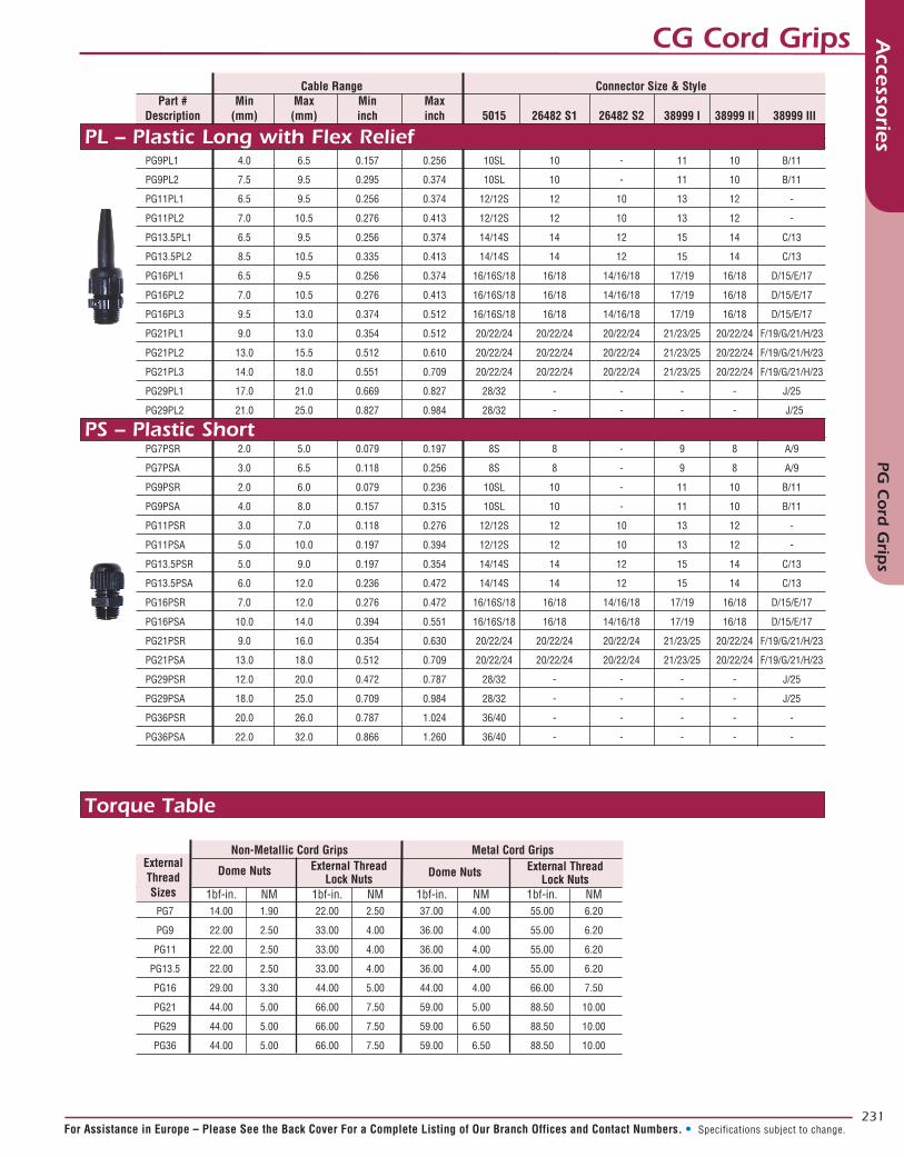
CG Cord Grips
Cable Range Connector Size & Style Part # Min Max Min Max Description (mm) (mm) inch inch 5015 26482 S1 26482 S2 38999 I 38999 II 38999 III
PG7ML1 - - - - 8S 8 - 9 8 A/9
PG7ML2 - - - - 8S 8 - 9 8 A/9
PG9ML1 4.0 6.5 0.157 0.256 10SL 10 - 11 10 B/11
PG9ML2 7.5 9.5 0.295 0.374 10SL 10 - 11 10 B/11
PG11ML1 6.5 9.5 0.256 0.374 12/12S 12 10 13 12 -
PG11ML2 7.0 10.5 0.276 0.413 12/12S 12 10 13 12 -
PG13.5ML1 6.5 9.5 0.256 0.374 14/14S 14 12 15 14 C/13
PG13.5ML2 8.5 10.5 0.335 0.413 14/14S 14 12 15 14 C/13
PG16ML1 6.5 9.5 0.256 0.374 16/16S/18 16/18 14/16/18 17/19 16/18 D/15/E/17
PG16ML2 7.0 10.5 0.276 0.413 16/16S/18 16/18 14/16/18 17/19 16/18 D/15/E/17
PG16ML3 9.5 13.0 0.374 0.512 16/16S/18 16/18 14/16/18 17/19 16/18 D/15/E/17
PG21ML1 9.0 13.0 0.354 0.512 20/22/24 20/22/24 20/22/24 21/23/25 20/22/24 F/19/G/21/H23
PG21ML2 13.0 15.5 0.512 0.610 20/22/24 20/22/24 20/22/24 21/23/25 20/22/24 F/19/G/21/H23
PG21ML3 14.0 18.0 0.551 0.709 20/22/24 20/22/24 20/22/24 21/23/25 20/22/24 F/19/G/21/H23
PG29ML1 17.0 21.0 0.669 0.827 28/32 - - - - J/25
PG29ML2 21.0 25.0 0.827 0.984 28/32 - - - - J/25
PG7MSR 2.0 5.0 0.079 0.197 8S 8 - 9 8 A/9
PG7MSA 3.0 6.5 0.118 0.256 8S 8 - 9 8 A/9
PG9MSR 2.0 6.0 0.079 0.236 10SL 10 - 11 10 B/11
PG9MSA 4.0 8.0 0.157 0.315 10SL 10 - 11 10 B/11
PG11MSR 3.0 7.0 0.118 0.276 12/12S 12 10 13 12 -
PG11MSA 5.0 10.0 0.197 0.394 12/12S 12 10 13 12 -
PG13.5MSR 5.0 9.0 0.197 0.354 14/14S 14 12 15 14 C/13
PG13.5MSA 6.0 12.0 0.236 0.472 14/14S 14 12 15 14 C/13
PG16MSR 7.0 12.0 0.276 0.472 16/16S/18 16/18 14/16/18 17/19 16/18 D/15/E/17
PG16MSA 10.0 14.0 0.394 0.551 16/16S/18 16/18 14/16/18 17/19 16/18 D/15/E/17
PG21MSR 9.0 16.0 0.354 0.630 20/22/24 20/22/24 20/22/24 21/23/25 20/22/24 F/19/G/21/H23
PG21MSA 13.0 18.0 0.512 0.709 20/22/24 20/22/24 20/22/24 21/23/25 20/22/24 F/19/G/21/H23
PG29MSR 12.0 20.0 0.472 0.787 28/32 - - - - J/25
PG29MSA 18.0 25.0 0.709 0.984 28/32 - - - - J/25
PG36MSR 20.0 26.0 0.787 1.024 36/40 - - - - -
PG36MSA 22.0 32.0 0.866 1.260 36/40 - - - - -
PG7PFR 2.0 5.0 0.079 0.197 8S 8 - 9 8 A/9
PG7PFA 3.0 6.5 0.118 0.256 8S 8 - 9 8 A/9
PG9PFR 2.0 6.0 0.079 0.236 10SL 10 - 11 10 B/11
PG9PFA 4.0 8.0 0.157 0.315 10SL 10 - 11 10 B/11
PG11PFR 3.0 7.0 0.118 0.276 12/12S 12 10 13 12 -
PG11PFA 5.0 10.0 0.197 0.394 12/12S 12 10 13 12 -
PG13.5PFR 5.0 9.0 0.197 0.354 14/14S 14 12 15 14 C/13
PG13.5PFA 6.0 12.0 0.236 0.472 14/14S 14 12 15 14 C/13
PG16PFR 7.0 12.0 0.276 0.472 16/16S/18 16/18 14/16/18 17/19 16/18 D/15/E/17
PG16PFA 10.0 14.0 0.394 0.551 16/16S/18 16/18 14/16/18 17/19 16/18 D/15/E/17
PG21PFR 9.0 16.0 0.354 0.630 20/22/24 20/22/24 20/22/24 21/23/25 20/22/24 F/19/G/21/H23
PG21PFA 13.0 18.0 0.512 0.709 20/22/24 20/22/24 20/22/24 21/23/25 20/22/24 F/19/G/21/H23
ML – Metal Long with Flex Relief Nickel Plated Brass
MS – Metal Short with Nickel Plated Brass
PF – Plastic with Spring Flex Relief
231
Accesso
riesM
enu D
For Assistance in Europe – Please See the Back Cover For a Complete Listing of Our Branch Offices and Contact Numbers. • Specifications subject to change.
Accesso
riesPG
Cord
Grip
s
Cable Range Connector Size & Style Part # Min Max Min Max Description (mm) (mm) inch inch 5015 26482 S1 26482 S2 38999 I 38999 II 38999 III
PG9PL1 4.0 6.5 0.157 0.256 10SL 10 - 11 10 B/11
PG9PL2 7.5 9.5 0.295 0.374 10SL 10 - 11 10 B/11
PG11PL1 6.5 9.5 0.256 0.374 12/12S 12 10 13 12 -
PG11PL2 7.0 10.5 0.276 0.413 12/12S 12 10 13 12 -
PG13.5PL1 6.5 9.5 0.256 0.374 14/14S 14 12 15 14 C/13
PG13.5PL2 8.5 10.5 0.335 0.413 14/14S 14 12 15 14 C/13
PG16PL1 6.5 9.5 0.256 0.374 16/16S/18 16/18 14/16/18 17/19 16/18 D/15/E/17
PG16PL2 7.0 10.5 0.276 0.413 16/16S/18 16/18 14/16/18 17/19 16/18 D/15/E/17
PG16PL3 9.5 13.0 0.374 0.512 16/16S/18 16/18 14/16/18 17/19 16/18 D/15/E/17
PG21PL1 9.0 13.0 0.354 0.512 20/22/24 20/22/24 20/22/24 21/23/25 20/22/24 F/19/G/21/H/23
PG21PL2 13.0 15.5 0.512 0.610 20/22/24 20/22/24 20/22/24 21/23/25 20/22/24 F/19/G/21/H/23
PG21PL3 14.0 18.0 0.551 0.709 20/22/24 20/22/24 20/22/24 21/23/25 20/22/24 F/19/G/21/H/23
PG29PL1 17.0 21.0 0.669 0.827 28/32 - - - - J/25
PG29PL2 21.0 25.0 0.827 0.984 28/32 - - - - J/25
PG7PSA (3.0) (6.5) 0.118 0.256 8 8 - 9 8 A/9
PG7PSR 2.0 5.0 0.079 0.197 8S 8 - 9 8 A/9
PG7PSA 3.0 6.5 0.118 0.256 8S 8 - 9 8 A/9
PG9PSR 2.0 6.0 0.079 0.236 10SL 10 - 11 10 B/11
PG9PSA 4.0 8.0 0.157 0.315 10SL 10 - 11 10 B/11
PG11PSR 3.0 7.0 0.118 0.276 12/12S 12 10 13 12 -
PG11PSA 5.0 10.0 0.197 0.394 12/12S 12 10 13 12 -
PG13.5PSR 5.0 9.0 0.197 0.354 14/14S 14 12 15 14 C/13
PG13.5PSA 6.0 12.0 0.236 0.472 14/14S 14 12 15 14 C/13
PG16PSR 7.0 12.0 0.276 0.472 16/16S/18 16/18 14/16/18 17/19 16/18 D/15/E/17
PG16PSA 10.0 14.0 0.394 0.551 16/16S/18 16/18 14/16/18 17/19 16/18 D/15/E/17
PG21PSR 9.0 16.0 0.354 0.630 20/22/24 20/22/24 20/22/24 21/23/25 20/22/24 F/19/G/21/H/23
PG21PSA 13.0 18.0 0.512 0.709 20/22/24 20/22/24 20/22/24 21/23/25 20/22/24 F/19/G/21/H/23
PG29PSR 12.0 20.0 0.472 0.787 28/32 - - - - J/25
PG29PSA 18.0 25.0 0.709 0.984 28/32 - - - - J/25
PG36PSR 20.0 26.0 0.787 1.024 36/40 - - - - -
PG36PSA 22.0 32.0 0.866 1.260 36/40 - - - - -
PL – Plastic Long with Flex Relief
PS – Plastic Short
CG Cord Grips
Non-Metallic Cord Grips Metal Cord Grips 1bf-in. NM 1bf-in. NM 1bf-in. NM 1bf-in. NM PG7 14.00 1.90 22.00 2.50 37.00 4.00 55.00 6.20
PG9 22.00 2.50 33.00 4.00 36.00 4.00 55.00 6.20
PG11 22.00 2.50 33.00 4.00 36.00 4.00 55.00 6.20
PG13.5 22.00 2.50 33.00 4.00 36.00 4.00 55.00 6.20
PG16 29.00 3.30 44.00 5.00 44.00 4.00 66.00 7.50
PG21 44.00 5.00 66.00 7.50 59.00 5.00 88.50 10.00
PG29 44.00 5.00 66.00 7.50 59.00 6.50 88.50 10.00
PG36 44.00 5.00 66.00 7.50 59.00 6.50 88.50 10.00
ExternalThreadSizes
External ThreadLock Nuts
External ThreadLock Nuts
Dome Nuts Dome Nuts
Torque Table

232
Accesso
riesM
enu D
In North America: Pricing Delivery: 800-642-8750 • Tech Support: 800-523-0727 • www.peigenesis.com • Specifications subject to change.
CG Cord Grips – Metal Short ShieldedAccesso
riesC
G C
ord
Grip
s – Metal Sh
ort Sh
ielded
Cable Diameter Shield Diameter Connector Series Shell Size Part # Style Min Max Min Max Min Max Min Max Description mm mm inch inch mm mm inch inch 5015 26482 S1 26482 S2 38999 I 38999 II 38999 III PG7MSS1 A 4.0 6.0 0.157 0.236 1.5 4.0 0.059 0.157 8S 8 - 9 8 A/9 PG7MSS2 A 6.0 9.5 0.236 0.374 1.5 6.5 0.059 0.256 8S 8 - 9 8 A/9 PG9MSS1 A 4.0 6.5 0.157 0.256 1.5 4.0 0.059 0.157 10SL 10 - 11 10 B/11 PG9MSS2 A 6.5 9.5 0.256 0.374 2.5 6.5 0.098 0.256 10SL 10 - 11 10 B/11 PG9MSS3 B 8.0 10.5 0.315 0.413 3.5 8.5 0.138 0.335 10SL 10 - 11 10 B/11 PG11MSS1 A 6.5 9.5 0.256 0.374 3.5 8.5 0.138 0.335 12/12S 12 10 13 12 - PG11MSS2 A 8.0 10.5 0.315 0.413 3.5 8.5 0.138 0.335 12/12S 12 10 13 12 - PG11MSS3 B 9.0 13.0 0.354 0.512 6.5 10.5 0.256 0.413 12/12S 12 10 13 12 - PG13.5MSS1 A 6.5 9.5 0.256 0.374 2.5 6.5 0.098 0.256 14/14S 14 12 15 14 C/13 PG13.5MSS2 A 7.0 10.5 0.276 0.413 3.0 8.0 0.118 0.315 14/14S 14 12 15 14 C/13 PG13.5MSS3 A 9.0 13.0 0.354 0.512 6.5 10.5 0.256 0.413 14/14S 14 12 15 14 C/13 PG16MSS1 A 6.5 9.5 0.256 0.374 3.5 8.0 0.138 0.315 16/16S/18 16/18 14/16/18 17/19 16/18 D/15/E/17 PG16MSS2 A 7.0 10.5 0.276 0.413 4.5 8.0 0.177 0.315 16/16S/18 16/18 14/16/18 17/19 16/18 D/15/E/17 PG16MSS3 A 9.0 13.0 0.354 0.512 4.5 8.0 0.177 0.315 16/16S/18 16/18 14/16/18 17/19 16/18 D/15/E/17 PG16MSS4 B 11.5 15.5 0.453 0.610 9.5 13.5 0.374 0.531 16/16S/18 16/18 14/16/18 17/19 16/18 D/15/E/17 PG16MSS5 B 14.0 18.0 0.551 0.709 10.5 14.5 0.413 0.571 16/16S/18 16/18 14/16/18 17/19 16/18 D/15/E/17 PG21MSS1 A 9.0 13.0 0.354 0.512 5.5 9.5 0.217 0.374 20/22/24 20/22/24 20/22/24 21/23/25 20/22/24 F/19/G/21/H/23 PG21MSS2 A 11.5 15.5 0.453 0.610 9.5 13.5 0.374 0.531 20/22/24 20/22/24 20/22/24 21/23/25 20/22/24 F/19/G/21/H/23 PG21MSS3 B 17.0 20.0 0.669 0.787 13.0 18.0 0.512 0.709 20/22/24 20/22/24 20/22/24 21/23/25 20/22/24 F/19/G/21/H/23 PG21MSS4 B 20.0 25.0 0.787 0.984 15.0 21.0 0.591 0.827 20/22/24 20/22/24 20/22/24 21/23/25 20/22/24 F/19/G/21/H/23 PG29MSS1 A 20.0 25.0 0.787 0.984 15.0 20.0 0.591 0.787 28/32 - - - - J/25 PG29MSS2 B 24.0 28.0 0.945 1.102 18.0 25.5 0.709 1.004 28/32 - - - - J/25 PG29MSS3 B 17.0 32.0 0.669 1.260 24.0 31.0 0.945 1.220 28/32 - - - - J/25 PG29MSS4 B 29.0 34.0 1.142 1.339 24.0 31.0 0.945 1.220 28/32 - - - - J/25 PG36MSS1 A 24.0 28.0 0.945 1.102 18.0 25.5 0.709 1.004 36/40 - - - - - PG36MSS2 A 29.0 34.0 1.142 1.339 24.0 31.0 0.945 1.220 36/40 - - - - -
Shielding Effectiveness
Note: Cable shield diameters may be calculated by subtracting the cable jacket thickness multiplied by two from the cable outside diameters.
Cable OD – (Jacket Thickness X 2) = Shield Diameter

233
Accesso
riesM
enu D
For Assistance in Europe – Please See the Back Cover For a Complete Listing of Our Branch Offices and Contact Numbers. • Specifications subject to change.
Accesso
riesC
ord
Grip
and
Con
duit Th
read A
dap
tersCord Grip and Conduit Thread Adapters
Internal Thread PG7 PG9 PG11 PG13.5 PG16 PG21 PG29 PG36 PG42 PG48 22866.9 - - - - - - - - 22800.9 22867.9 22868.9 - - - - - - 22801.9 22802.9 22869.9 22870.9 22871.9 - - - - 22803.9 22804.9 22805.9 22872.9 22873.9 - - - - 22806.9 22807.9 22808.9 22809.9 22874.9 22875.9 - - - - - 22810.9 22811.9 22812.9 22876.9 - - - - - - 22813.9 22814.9 22815.9 22877.9 - - - - - - - 22816.9 22817.9 22878.9 - - - - - - - 22818.9 22819.9 22879.9 - - - - - - 22820.9 22821.9 -
PG7 PG9 PG11 PG13.5 PG16 PG21 PG29 PG36 PG42 PG48
Exte
rnal
Thr
ead
Solid Insert (Drill Your Own) Black Plastic Metal (NPB) Drillable Area PG7 20920.6 call PG9 20921.1 20921.6 (10) 0.39” PG11 20922.1 20922.6 (11) 0.43” PG13.5 20923.1 20923.6 (13) 0.51” PG16 20924.1 20924.6 (16) 0.63” PG21 20925.1 20925.6 (21) 0.83” PG29 20926.1 20926.6 (28) 1.10”Add O-Ring to Plastic
Drilling Instructions1. Cool insert to 45°F (7°C)
2. Place cord grip & insert in a vise or holding fixture with the threaded side facing drill
3. Cool insert with air or water during drilling
4. Maximum drill speed of 800 rpm
5. Minimum spacing between holes and or shell (1mm) 0.38”
O-Ring/Seal Rings Lock Nuts Perbunan Silicone Black Nickel Plated -20° to +120°C -60° to +200°C Polyamide Brass PG7 23150.9 23230.9 23060.9 23000.9 PG9 23151.9 23231.9 23061.9 23001.9 PG11 23152.9 23232.9 23062.9 23002.9 PG13.5 23153.9 23233.9 23063.9 23003.9 PG16 23154.9 23234.9 23064.9 23004.9 PG21 23155.9 23235.9 23065.9 23005.9 PG29 23156.9 23236.9 23066.9 23006.9 PG36 23157.9 23237.9 PG42 23158.9 PG48 23159.9
Enlargers
Reducers

234
Accesso
riesM
enu D
In North America: Pricing Delivery: 800-642-8750 • Tech Support: 800-523-0727 • www.peigenesis.com • Specifications subject to change.
Accesso
ries1
-3 H
ole C
ord
Grip
s
1-3 Hole Cord GripsNumber of Part Numbers Hole Size Hole Size Hole Size Wire Black Metal PG Thread # of # of Cavities Plastic PA NBP size thread (mm) Inch A Holes (mm) Inch B Holes (mm) Inch 21305.1 21305.6 9 (3.0) 0.118 21318.1 21318.6 11 (3.0) 0.118 21306.1 21306.6 9 (4.0) 0.157 21319.1 21319.6 11 (4.0) 0.157 21357.1 21357.6 16 (4.0) 0.157 21307.1 21307.6 9 (5.0) 0.197 1 21320.1 21320.6 11 (5.0) 0.197 21358.1 21358.6 16 (5.0) 0.197 21339.1 21339.6 13.5 (8.0) 0.315 21359.1 21359.6 16 (8.0) 0.315 21396.1 21396.6 21 (16.0) 0.630 21446.1 21446.6 29 (16.0) 0.630 21308.1 21308.6 9 (1.2) 0.047
21321.1 21321.6 11 (2.3) 0.091 21309.1 21309.6 9 (3.0) 0.118 21322.1 21322.6 11 (3.0) 0.118 21340.1 21340.6 13.5 (3.0) 0.118 21310.1 21310.6 9 (4.0) 0.157 21323.1 21323.6 11 (4.0) 0.157 21360.1 21360.6 16 (4.0) 0.157 21398.1 21398.6 21 (4.5) 0.177 21324.1 21324.6 11 (5.0) 0.197 21341.1 21341.6 13.5 (5.0) 0.197 21325.1 21325.6 11 (6.0) 0.236 21342.1 21342.6 13.5 (6.0) 0.236 21361.1 21361.6 16 (6.0) 0.236 21362.1 21362.6 16 (8.0) 0.315 21399.1 21399.6 21 (8.0) 0.315 2 21400.1 21400.6 21 (9.0) 0.354 21447.1 21447.6 29 (11.0) 0.433 21448.1 21448.6 29 (13.0) 0.512 21481.1 21481.6 36 (15.0) 0.591 21376.1 21376.6 16 Combinations Q 1 (3.0) 0.118 1 (8.0) 0.315 21377.1 21377.6 16 Combinations Q 1 (3.0) 0.118 1 (9.0) 0.354 21381.1 21381.6 16 Combinations Q 1 (6.0) 0.236 1 (8.0) 0.315 21415.1 21415.6 21 Combinations Q 1 (7.0) 0.276 1 (10.5) 0.413 21416.1 21416.6 21 Combinations Q 1 (8.5) 0.335 1 (12.0) 0.472 21465.1 21465.6 29 Combinations Q 1 (12.0) 0.472 1 (13.0) 0.512 21467.1 21467.6 29 Combinations Q 1 (6.5) 0.256 1 (17.0) 0.669 21471.1 21471.6 29 Combinations Q 1 (9.0) 0.354 1 (15.0) 0.591 21493.1 21493.6 36 Combinations Q 1 (11.0) 0.433 1 (21.0) 0.827 21494.1 21494.6 36 Combinations Q 1 (12.5) 0.492 1 (16.5) 0.650 21495.1 21495.6 36 Combinations Q 1 (13.0) 0.512 1 (16.5) 0.650 21496.1 21496.6 36 Combinations Q 1 (14.0) 0.551 1 (17.0) 0.669
21343.1 21343.6 13.5 (2.0) 0.079 21311.1 21311.6 9 (3.0) 0.118 21326.1 21326.6 11 (3.0) 0.118 21344.1 21344.6 13.5 (3.0) 0.118 21364.1 21364.6 16 (3.0) 0.118 21327.1 21327.6 11 (4.0) 0.157 21345.1 21345.6 13.5 (4.0) 0.157 21346.1 21346.6 13.5 (5.3) 0.209 21365.1 21365.6 16 (7.0) 0.276 21401.1 21401.6 21 (7.0) 0.276 3 21402.1 21402.6 21 (9.0) 0.354 21482.1 21482.6 36 (10.0) 0.394 21449.1 21449.6 29 (11.0) 0.433 21351.1 21351.6 13.5 Combinations Q 1 (3.0) 0.118 2 (6.0) 0.236 21353.1 21353.6 13.5 Combinations Q 2 (5.0) 0.197 1 (5.5) 0.217 21378.1 21378.6 16 Combinations Q 1 (3.0) 0.118 2 (8.0) 0.315 21379.1 21379.6 16 Combinations Q 1 (5.0) 0.197 2 (6.0) 0.236 21382.1 21382.6 16 Combinations Q 2 (5.0) 0.197 1 (6.0) 0.236 21383.1 21383.6 16 Combinations Q 2 (6.0) 0.236 1 (7.0) 0.276 21384.1 21384.6 16 Combinations Q 2 (6.0) 0.236 1 (8.0) 0.315 21414.1 21414.6 21 Combinations Q 1 (6.0) 0.236 2 (9.0) 0.354 21473.1 21473.6 29 Combinations Q 2 (6.5) 0.256 1 (10.0) 0.394
Q Combination = more than one diameter size hole

235
Accesso
riesM
enu D
For Assistance in Europe – Please See the Back Cover For a Complete Listing of Our Branch Offices and Contact Numbers. • Specifications subject to change.
Accesso
ries4
-15
Hole C
ord
Grip
s4-15 Hole Cord Grips
Number of Part Numbers Hole Size Hole Size Hole Size Wire Black Metal PG Thread # of # of Cavities Plastic PA NBP size thread (mm) Inch A Holes (mm) Inch B Holes mm Inch 21312.1 21312.6 9 (1.4) 0.055 21328.1 21328.6 11 (1.5) 0.059 21313.1 21313.6 9 (3.0) 0.118 21347.1 21347.6 13.5 (3.0) 0.118 21366.1 21366.6 16 (4.0) 0.157 21403.1 21403.6 21 (5.0) 0.197 21451.1 21451.6 29 (5.5) 0.217 21367.1 21367.6 16 (6.0) 0.236 21404.1 21404.6 21 (6.0) 0.236 4 21405.1 21405.6 21 (6.5) 0.256 21406.1 21406.6 21 (8.0) 0.315 21452.1 21452.6 29 (8.0) 0.315 21453.1 21453.6 29 (9.0) 0.354 21450.1 21450.6 29 (10.0) 0.394 21483.1 21483.6 36 (10.2) 0.402 21484.1 21484.6 36 (11.5) 0.453 21485.1 21485.6 36 (13.0) 0.512 21354.1 21354.6 13.5 Combinations Q 2 (3.0) 0.118 1 (6.5) 0.256 21385.1 21385.6 16 Combinations Q 3 (4.0) 0.157 1 (9.0) 0.354 21419.1 21419.6 21 Combinations Q 2 (6.0) 0.236 2 (8.0) 0.315 21329.1 21329.6 11 (3.5) 0.138
21455.1 21455.6 29 (8.0) 0.315 21456.1 21456.6 29 (9.0) 0.354 5 21454.1 21454.6 29 (10.0) 0.394 21486.1 21486.6 36 (11.5) 0.453 21420.1 21420.6 21 Combinations Q 2 (7.0) 0.276 3 (7.0) 0.276 21477.1 21477.6 29 Combinations Q 4 (5.5) 0.217 1 (8.0) 0.315
21330.1 21330.6 11 (2.0) 0.079 21331.1 21331.6 11 (2.5) 0.098 21348.1 21348.6 13.5 (3.5) 0.138 21368.1 21368.6 16 (4.0) 0.157 21407.1 21407.6 21 (4.0) 0.157 6 21408.1 21408.6 21 (5.0) 0.197 21409.1 21409.6 21 (5.5) 0.217 21457.1 21457.6 29 (6.0) 0.236 21410.1 21410.6 21 (6.5) 0.256 21458.1 21458.6 29 (8.0) 0.315 21475.1 21475.6 29 Combinations Q 3 (7.0) 0.276 3 (8.0) 0.315
21332.1 21332.6 11 (1.5) 0.059 21369.1 21369.6 16 (2.0) 0.079 7 21459.1 21459.6 29 (7.0) 0.276 21487.1 21487.6 36 (9.0) 0.354 21424.1 21424.6 21 Combinations Q 6 (4.0) 0.157 1 (7.0) 0.276 21479.1 21479.6 29 Combinations Q 4 (6.0) 0.236 3 (8.5) 0.335
21349.1 21349.6 13.5 (1.5) 0.059 21411.1 21411.6 21 (3.0) 0.118 21412.1 21412.6 21 (4.0) 0.157 8 21412.1 21412.6 21 (5.0) 0.197 21460.1 21460.6 29 (5.5) 0.217 21488.1 21488.6 36 (8.0) 0.315 21489.1 21489.6 36 (9.0) 0.354
9 21333.1 21333.6 11 (1.5) 0.059 21370.1 21370.6 16 (3.0) 0.118
10 21350.1 21350.6 13.5 (2.0) 0.079 21461.1 21461.6 29 (6.0) 0.236
11 21490.1 21490.6 36 (8.0) 0.315
12 21462.1 21462.6 29 (5.3) 0.209
13 21491.1 21491.6 36 (7.0) 0.276
15 21492.1 21492.6 36 (5.0) 0.197
Q Combination = more than one diameter size hole

236
Accesso
riesM
enu D
In North America: Pricing Delivery: 800-642-8750 • Tech Support: 800-523-0727 • www.peigenesis.com • Specifications subject to change.
Conduit AssembliesAccesso
riesC
on
duit A
ssemblies
Complex Assembly - FLEXAquick System

237
Accesso
riesM
enu D
For Assistance in Europe – Please See the Back Cover For a Complete Listing of Our Branch Offices and Contact Numbers. • Specifications subject to change.
Conduit Assemblies Accesso
riesC
on
duit A
ssemblies
Finished Products

238
Accesso
riesM
enu D
In North America: Pricing Delivery: 800-642-8750 • Tech Support: 800-523-0727 • www.peigenesis.com • Specifications subject to change.
ConduitsAccesso
riesC
on
duits
Conduit Code 07 10 12 14 17 23 29 36 48 Trade Size AD10.0 AD13.0 AD15.8 AD18.5 AD21.2 AD28.5 AD34.5 AD42.5 AD54.5 7 5020.026.207 5020.027.201 9 5020.027.202 5020.026.209 11 5020.027.203 5020.027.204 5020.026.211 13.5 5020.027.205 5020.027.206 5020.027.207 5020.026.213 5020.027.209 16 5020.027.210 5020.026.214 5020.026.216 5020.027.208 21 5020.026.221 29 5020.026.229 36 5020.026.236 48 5020.026.248
Straight PG Adapters
Right Angle PG Adapters
Seal and Jam Nuts PG
PG T
hrea
d
Conduit Code 07 10 12 14 17 23 29 36 48 Trade Size AD10.0 AD13.0 AD15.8 AD18.5 AD21.2 AD28.5 AD34.5 AD42.5 AD54.5 7 5020.028.207 9 5020.028.209 11 5020.029.211 5020.028.211 13.5 5020.029.213 5020.028.213 16 5020.028.216 21 5020.028.221 29 5020.028.229 36 5020.028.236 48 5020.028.248
PG T
hrea
d
Seals Nuts O-Rings Flat Gaskets Metal Plastic
7 0330.000.007 0331.000.007 0530.000.007 0310.000.007 9 0330.000.009 0331.000.009 0530.000.009 0310.000.009 11 0330.000.011 0331.000.011 0530.000.011 0310.000.011 13 0330.000.013 0331.000.013 0530.000.013 0310.000.013 16 0330.000.016 0331.000.016 0530.000.016 0310.000.016 21 0330.000.021 0331.000.021 0530.000.021 0310.000.021 29 0330.000.029 0331.000.029 0530.000.029 0310.000.029 36 0330.000.036 0331.000.036 0530.000.036 0310.000.036 48 0330.000.048 0331.000.048 0530.000.048 0310.000.048
PG T
hrea
d
Externally threaded PG Adapters are used to attach conduit directly to a box or panel for installations that will not need to be disconnected frequently. Panel Seals prevent dust and fluids from getting inside. Jam nuts simplifythe attachment to the panel without having to tap pre-threaded panel holes.
D
Panel Cutouts D +/-(0.2) .008 (mm) Inch PG7 (13.0) 0.512 PG9 (15.7) 0.618 PG11 (19.0) 0.748 PG13.5 (21.0) 0.827 PG16 (23.0) 0.906 PG21 (28.8) 1.134 PG29 (37.5) 1.476 PG36 (47.5) 1.870 PG48 (59.8) 2.354

239
Accesso
riesM
enu D
For Assistance in Europe – Please See the Back Cover For a Complete Listing of Our Branch Offices and Contact Numbers. • Specifications subject to change.
Conduits Accesso
riesC
on
duits
Conduit Code 07 10 12 17 23 29 36 48 Trade Size AD10.0 AD13.0 AD15.8 AD21.2 AD28.5 AD34.5 AD42.5 AD54.5 M10x1.5 5020.037.210 M12x1.5 5020.065.203 5020.037.212 M16X1.5 5020.065.205 5020.037.216 M20X1.5 5020.065.207 5020.037.220 M25X1.5 5020.065.209 5020.037.225 M32X1.5 5020.065.211 5020.037.232 M40X1.5 5020.037.238 5020.037.240 M50X1.5 5020.037.245 5020.037.250 M63X1.5 5020.037.236
Straight Metric Adapters
Right Angle Metric Adapters
Seal and Jam Nuts Metric
Met
ric
Thre
ad
Conduit Code 07 10 12 17 23 29 36 48 Trade Size AD10.0 AD13.0 AD15.8 AD21.2 AD28.5 AD34.5 AD42.5 AD54.5 M10x1.5 5020.064.210 M12x1.5 5020.064.212 M16X1.5 5020.036.216 5020.064.216 M20X1.5 5020.036.220 5020.064.220 M25X1.5 5020.036.225 5020.064.225 M32X1.5 5020.036-232 5020.064.232 M40X1.5 5020.036.240 5020.064.240 M50X1.5 5020.036.250 5020.064.250 M63X1.5 5020.036.263
Met
ric
Thre
ad
Seals Nuts O-Rings Flat Gaskets Metal Plastic
M10x1.0 0330.001.010 0333.000.010 0531.000.010 0309.000.210 M12x1.5 0330.001.012 0333.000.012 0531.000.012 0309.000.212 M16X1.5 0330.001.016 0333.000.016 0531.000.016 0309.000.216 M20X1.5 0330.001.020 0333.000.020 0531.000.020 0309.000.220 M25X1.5 0330.001.025 0333.000.025 0531.000.025 0309.000.225 M32X1.5 0330.001.032 0333.000.032 0531.000.032 0309.000.232 M40X1.5 0330.001.040 0333.000.040 0531.000.040 0309.000.240 M50X1.5 0330.001.050 0333.000.050 0531.000.050 0309.000.250 M63X1.5 0330.001.063 0333.000.063 0531.000.063 0309.000.263
Met
ric
Thre
ad
Now a European Standard. These externally threaded Metric Adapters are used to attach conduit directly to a box or panel for installations that will not need to be disconnected frequently. Panel Seals prevent dust and fluids from getting inside. Jam nuts simplify the attachment to the panel without having to tap pre-threaded panel holes.
D
Panel Cutouts D +/-(0.2) .008 (mm) Inch M10x1.5 (10.3) 0.406 M12x1.5 (12.3) 0.484 M16x1.5 (16.3) 0.642 M20x1.5 (20.3) 0.799 M25x1.5 (25.3) 0.996 M32x1.5 (32.3) 1.272 M40x1.5 (40.4) 1.591 M50x1.5 (50.4) 1.984 M63x1.5 (63.4) 2.496

240
Accesso
riesM
enu D
In North America: Pricing Delivery: 800-642-8750 • Tech Support: 800-523-0727 • www.peigenesis.com • Specifications subject to change.
Conduits – PA6Accesso
riesC
on
duits – P
A6
Heavy-duty cable conduits are manufactured using modified polyamides that are free of halogen and cadmium. These impact resistant conduits are rugged, easy to install and provide excellent resistance to UV rays and environmental corrosion.They are UL recognized: file # E86359. Flammability rating: UL94V0Temperature range: -58°F to +221°F; short term +302°F (-50°C to +105°C; short term +150°C)
d1d2
R
Bend Radius R Trade Inches (mm) PA6 Part Number Code Size d1 d2 Static Dynamic 0233.202.006 07 AD10.0 (6.5) (10.0) (13.0) (35.0) 0.256 0.394 0.512 1.378 0233.202.010 10 AD13.0 (10.0) (13.0) (20.0) (45.0) 0.394 0.512 0.787 1.772 0233.202.012 12 AD15.8 (12.0) (15.8) (35.0) (55.0) 0.472 0.622 1.378 2.165 0233.202.014 14 AD18.5 (14.3) (18.2) (40.0) (65.0) 0.563 0.717 1.575 2.559 0233.202.016 17 AD21.2 (16.5) (21.2) (45.0) (75.0) 0.650 0.835 1.772 2.953 0233.202.023 23 AD28.5 (23.0) (28.5) (55.0) (100.0) 0.906 1.122 2.165 3.937 0233.202.029 29 AD34.5 (29.0) (34.5) (65.0) (120.0) 1.142 1.358 2.559 4.724 0233.202.036 36 AD42.5 (36.0) (42.5) (90.0) (150.0) 1.417 1.673 3.543 5.906 0233.202.048 48 AD54.5 (48.0) (54.5) (100.0) (190.0) 1.890 2.146 3.937 7.480
High Impact Resistance in Cold, Flexible
AD10.0 AD13.0 AD15.8 AD18.2 AD21.2 AD28.5
2.7
2.7
2.7
3.3
3.3
3.3
10.0 13.0 15.8 18.2 21.2 28.5
07 10 12 14 17 23
PA6 & PA12 Conduit Dimension AD10.0 to AD28.5
Tubing Cutterup to AD34.5(07 to 29)0433.000.010
241
Accesso
riesM
enu D
For Assistance in Europe – Please See the Back Cover For a Complete Listing of Our Branch Offices and Contact Numbers. • Specifications subject to change.
PA12 – Conduits Accesso
riesC
on
duits – P
A1
2
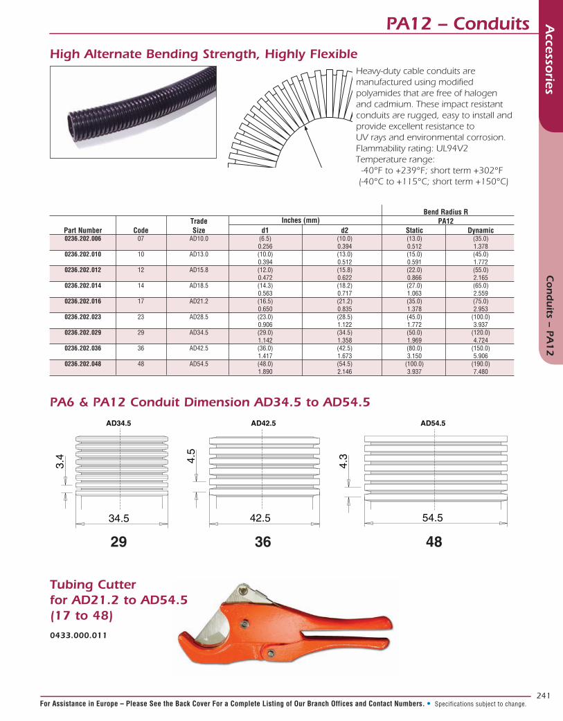
Heavy-duty cable conduits are manufactured using modified polyamides that are free of halogen and cadmium. These impact resistant conduits are rugged, easy to install and provide excellent resistance to UV rays and environmental corrosion.Flammability rating: UL94V2Temperature range: -40°F to +239°F; short term +302°F (-40°C to +115°C; short term +150°C)
Bend Radius R Trade Inches (mm) PA12 Part Number Code Size d1 d2 Static Dynamic 0236.202.006 07 AD10.0 (6.5) (10.0) (13.0) (35.0) 0.256 0.394 0.512 1.378 0236.202.010 10 AD13.0 (10.0) (13.0) (15.0) (45.0) 0.394 0.512 0.591 1.772 0236.202.012 12 AD15.8 (12.0) (15.8) (22.0) (55.0) 0.472 0.622 0.866 2.165 0236.202.014 14 AD18.5 (14.3) (18.2) (27.0) (65.0) 0.563 0.717 1.063 2.559 0236.202.016 17 AD21.2 (16.5) (21.2) (35.0) (75.0) 0.650 0.835 1.378 2.953 0236.202.023 23 AD28.5 (23.0) (28.5) (45.0) (100.0) 0.906 1.122 1.772 3.937 0236.202.029 29 AD34.5 (29.0) (34.5) (50.0) (120.0) 1.142 1.358 1.969 4.724 0236.202.036 36 AD42.5 (36.0) (42.5) (80.0) (150.0) 1.417 1.673 3.150 5.906 0236.202.048 48 AD54.5 (48.0) (54.5) (100.0) (190.0) 1.890 2.146 3.937 7.480
High Alternate Bending Strength, Highly Flexible
AD54.5AD42.5AD34.5
3.4 4.5
4.3
34.5 42.5 54.5
29 36 48
PA6 & PA12 Conduit Dimension AD34.5 to AD54.5
Tubing Cutterfor AD21.2 to AD54.5(17 to 48)0433.000.011
d1d2
R

242
Accesso
riesM
enu D
In North America: Pricing Delivery: 800-642-8750 • Tech Support: 800-523-0727 • www.peigenesis.com • Specifications subject to change.
A Conduit Trade Straight Splice Reducer Code Size Part # Part # B Outlet Trade Size 10 AD13.0 - -
- -
12 AD15.8 - -
- -
17 AD21.2 5602.021.221 5601.015.221 12 AD15.8
- -
23 AD28.5 5602.028.228 5601.015.228 12 AD15.8
- 5601.021.228 17 AD21.2
29 AD34.5 5602.034.234 5601.015.234 12 AD15.8
- 5601.021.234 17 AD21.2
- 5601.028.234 23 AD28.5
36 AD42.5 5602.042.242 5601.034.242 29 AD34.5
48 AD54.5 5602.054.254 5601.042.254 36 AD42.5
- 5601.021.254 17 AD21.2
ConduitsAccesso
riesC
on
duits
Flexa Transitions
A Conduit Trade Y Splice T Splice Code Size Part # B Outlet Trade Size Part # B Outlet Trade Size 10 AD13.0 5020.032.201 07 AD10.0 -
5020.032.202 10 AD13.0 -
12 AD15.8 5020.032.203 10 AD13.0 5020.041.208 12 AD15.8
5020.032.204 12 AD15.8 -
17 AD21.2 5020.032.206 12 AD15.8 5020.041.201 17 AD21.2
- -
23 AD28.5 5020.032.208 17 AD21.2 5020.041.202 23 AD28.5
- -
29 AD34.5 5020.032.209 23 AD28.5 5020.041.210 23 AD28.5
- 5020.041.211 29 AD34.5
- -
36 AD42.5 5020.032.210 29 AD34.5 5020.041.212 36 AD42.5
48 AD54.5 5020.032.211 36 AD42.5 5020.041.213 48 AD54.5
- -
A B
A
B
B
Reducing
Non-Reducing
A
B
B
B B
Splices are used to join two lengths of conduit. They can be used to make conduit harnesses longer. Reducers are used to go from a larger adapter to smaller conduit.
Y and T Adapters are used to branch off or consolidate conduits.The inlet side “A” can be larger (more popular) or the same size as theoutlet side “B”.

243
Accesso
riesM
enu D
For Assistance in Europe – Please See the Back Cover For a Complete Listing of Our Branch Offices and Contact Numbers. • Specifications subject to change.
Accesso
riesPottin
g C
om
poun
ds &
Tools
Potting Compounds & ToolsPotting Guidelines for Cable Assemblies:
1. There is a wide range of potting compounds available in the market. We set out to select a concise group of potting compounds for general purpose use with electrical connectors. Each of the recommended materials has been tested by PEI-Genesis. If a more optimized potting compound is needed please contact us. One of our appli-cation engineers will gladly help you find the right potting compound for your design.
2. We recommend getting all of the cables ready and positioned before potting – especially if a quick cure speed potting compound is used. Fixtures, clamps or racks will help position the connector and cable while the potting compound hardens.
3. Adhesion can be improved by either cleaning surfaces with rubbing alcohol or roughening surfaces with sand paper.
4. When using a mixing nozzle insert it as far as possible into the endbell and fill upward. This will prevent air bubbles from forming beneath the potting compound.
5. Heat can be used to accelerate the hardening time of potting compounds. Be careful not to overheat them, especially if you are using a hot air gun or torch. Gentle heat (2 times room temperature) will significantly accelerate the hardening time.
6. For assemblies with heat shrink boots we recommend waiting until the potting compound working time has passed before recovering the heat shrink boot. Otherwise, the compound may overheat.
7. Clean up uncured potting compounds with rubbing alcohol.
DP100FR-XXML 720UR-XXML 3015C-XXML 3125-XXML Sure Seal X X
Trident
97 Series X X
MIL-DTL-5015 & P-lok X X X X
VG 95 234 & Bayonet X X X X
MIL-DTL-26482 & 62GB X X X X
MIL-DTL-38999 X X X X
D-Sub X X
Work Life 4-8 Min 5-6 Min 6-10 Min 15 -20 Min
Fixture Time 15-20 Min 1-2 Hours 15-20 Min 45-60 Min
Viscosity 120,000 cps 4,000 cps 12,000 cps 14,000 cps
Flows Like Ketchup Light Syrup Honey Honey Temperature Range -67° to +180°F -65° to + 200°F -67° to +250°F -40° to +225°F (-55° to +82°C) (-53° to + 93°C) (-55° to +121°C) (-40° to +107°C)
Color Beige Straw Clear Amber
Shore D Hardness 87 78 82 75 Flame Resistant per UL94 E61941 - - - DOT UN/NA # - - 2735* 2735* 30ml Trial Size X X
50ml X X X X
250ml/200ml** X** X X
400ml X X X
Mat
eria
l Inf
orm
atio
nPa
ckag
e Si
zes
Conn
ecto
r Se
ries
Potting Compound Types
* Special Shipping Requirements may apply, call for more information.
** 200ml only

244
Accesso
riesM
enu D
In North America: Pricing Delivery: 800-642-8750 • Tech Support: 800-523-0727 • www.peigenesis.com • Specifications subject to change.
Potting Compounds & ToolsAccesso
riesPottin
g C
om
poun
ds &
Tools
DP100 FR – Flame ResistantWorking Time: 5 to 8 minutesFixture Time: 15 to 20 minutesColor: BeigeMix Ratio: 1 to 1UL Rating: UL 94-V0 (File Number E61941)
Part Numbers:
PEI Comments: This epoxy is recommended for applications where the UL 94-V0flame test is required. It is not as thick as the S310 and has a moderate ability to flowbetween wires and into gaps. It is thicker than the 3015C and 3030 epoxies. Werecommend that users pay extra attention when using it, especially in tight wire bundles.It is important to make sure that potting nozzles are fully inserted to limit air bubblesbeneath the epoxy. Users may also want to move the nozzle around while potting tomake sure the entire wire bundle is encapsulated.
720UR – Low Viscosity PolyurethaneWorking Time: 5 to 6 minutesFixture Time: 1 - 2 hours Color: StrawMix Ratio: 1 to 1Operating Temperature: -65° to +200°F (-53° to +93°C)
Part Numbers:
PEI Comments: 720UR has a very low viscosity for a potting compound. That makesit a great choice for prototypes and low volume production since it is easier to pour intoendbells than most epoxies. It flows well and easily fills gaps between wires. 720URbonds well to PVC and Polyurethane wires and cables as well as a wide variety ofthermoplastics, metals, and connector insulators.
Package Type Part Number Mixing Nozzle Applicator Tool 50 ml 720UR-50ML 300-026 DK-104 or Caulk Adapter
3015C – Fast Cure EpoxyWorking Time: 6 to 10 minutesFixture Time: 15 to 20 minutesColor: ClearMix Ratio: 1 to 1Temperature Range: -67° to +250°F (-55° to +121°C)DOT UN/NA #: 2735*
Part Numbers:
PEI Comments: This is a great epoxy for small jobs since it flows well and hardensquickly. It may harden a little too fast if working time is needed between applications orif there is a dense wire bundle. Our advice for first time users is to get some extra mixingnozzles and to set up groups of cables in fixtures prior to potting.
Package Type Part Number Mixing Nozzle Applicator Tool Trial Size: 30 ml - Dual Syringe 3015C-30ML Not required Not required 50 ml 3015C-50ML 300-028 or 300-026 DK-104 or Caulk Adapter 250 ml 3015C-250ML 300-006 EXT-250/MNLGUN 400 ml 3015C-400ML 300-006 VBM-400X
Package Type Part Number Mixing Nozzle Applicator Tool 50 ml DP100FR-50ML 300-028 or 300-026 DK-104 or Caulk Adapter 200 ml DP100FR-200ML 300-006 EXT-250/MNLGUN 400 ml DP100FR-400ML 300-006 VBM-400X
* Special Shipping Requirements may apply, call for more information.

245
Accesso
riesM
enu D
For Assistance in Europe – Please See the Back Cover For a Complete Listing of Our Branch Offices and Contact Numbers. • Specifications subject to change.
Potting Compounds & Tools Accesso
riesPottin
g C
om
poun
ds &
Tools
3125 – Medium Cure Speed EpoxyWorking Time: 15 to 25 minutesFixture Time: 45 to 60 minutesColor: AmberMix Ratio: 1 to 1Temperature Range: -40° to +225°F (-40° to +107°C)DOT UN/NA #: 2735*
Part Numbers:
PEI Comments: 3125 is recommended for general purpose potting. It bonds well to plastics, metal and ceramics. It has a long enough working life to make it convenient for production or for applications where users need a little more working time. It flows well and does a good job of encapsulating small spaces and between wires. The longer working time also gives more time for air bubbles to work their way out before the epoxy hardens.
50 ml Handgun Applicator Tools50 ml Manual Handgun DK-104
50 ml Caulking Gun Conversion Kit DK-117
50 ml Pneumatic Handgun (not shown) CBA-25/94
250 ml Handgun Applicator Tools250 ml Manual Handgun EXT-250/MNLGUN
250 ml Pneumatic Handgun (not shown) TBA-250X
400 ml Handgun Applicator Tools400 ml Manual Handgun VBM-400X
400 ml Pneumatic Handgun (not shown) VBA-400X
Static Mixers for 50 ml Cartridges5.5mm x 16 Elements - Square Nozzle 300-028
5.3mm x 24 Elements - Square Nozzle 300-026
Static Mixers for 250 ml & 400 ml
7.5mm x 24 Elements - Square Nozzle 300-006
VBM-400X
300-028
300-006
DK-117300-026
Potting Compound
Package Type Part Number Mixing Nozzle Applicator Tool Trial Size: 30 ml - Dual Syringe 3125-30ML Not required Not required 50 ml 3125-50ML 300-028 or 300-026 DK-104 or Caulk Adapter 250 ml 3125-250ML 300-006 EXT-250/MNLGUN 400 ml 3125-400ML 300-006 VBM-400X
(not shown)
w/Bell Opening
* Special Shipping Requirements may apply, call for more information.

246
Accesso
riesM
enu D
In North America: Pricing Delivery: 800-642-8750 • Tech Support: 800-523-0727 • www.peigenesis.com • Specifications subject to change.
TapesAccesso
riesTap
es
There are a vast array of tapes available for many specialized applications. These are some of the most popular tape options for
cable harnessing.
PG93-03-003-1 48-1/2X520
33+ 27-1/2X66
HMT200A
1245CU Tape*Embossed Copper Foil Shielding and Grounding TapeColor: Copper Sealing: No UL E17385
The 1245 tape is a flexible, soft copper tape that has been embossed to allow continuity through the acrylic adhesive. The tape is recommended for static applications with limited bend-ing or flexing. Shielding effectiveness is 75dB to 85dB (30MHz to 1GHz). Drain wires can be soldered to this tape for ground connections between cables and connector shells.
PG93-03-003-1* Flexible Polyester Tape Plated with Nickel over CopperColor: Silver Sealing: No
This is our preferred choice for EMI Shielding. It works well in both static and flexing applications. Shielding effectiveness is 85dB (10MHz to 10GHz). This tape can be used for grounding by carefully soldering drain wires or with the use of conductive adhesives.
33+ PVC Tape PVC Electric TapeColor: Black Sealing: Yes Temperature: 0°F (-18°C) to 220°F (105°C) UL-E129200 CSA-LR48769
Scotch brand 33+ Super is an industry standard for all purpose insulating and splicing. It is rated to 600 volts and 220°F (105°C). Electrical Tape is often uses to bundle and seal cables. It conforms to irregular shapes, is tough and easy to apply. Install with at least two half lap layers for proper pro-tection. 33+ is also used as a protective layer over self fusing tapes, split con-duit and expandable sleeving.
HMT200AHot Melt TapeColor: Amber Sealing: Yes Temperature: -67°F (-55°C) to 221°F (105°C)
This is a heat activated adhesive used as a liner beneath heat shrink tubing or boots. It will improve both adhesion and fluid resistance. Cable surfaces should be free of dust or grease before application. For optimum performance we recommend that surfaces be cleaned and or roughened and then warmed slightly. Wrap a single layer of the tape tightly and with limited overlap. A soldering iron at a low temperature can be used to tack the tape in place. Then slide the heat shrink or boot in place. Use a heater to recover the heat shrink or boot and melt the tape. You should see some of the melted tape ooze out of the end of the heat shrink or boot. Allow the assembly to cool completely before bending or flexing.
27-1/2X66 High Strength Glass Cloth TapeColor: White (printable) Sealing: No Temperature: up to 266°F (130°C) UL-E17385 CSA-LR93411
This is a high tensile strength tape (150lb/in (262N/10mm)) with a thermosetting rubber adhesive. It is typically used to wrap individual wires into cable-like bundles. This tape is often used under heat shrink tubing. The heat shrink provides protection against fluids and dirt, while the tape provides much more tensile strength than heat shrink alone. One half lap layer is sufficient for low voltage applications. For voltages up to 600V, we recommend a minimum of two half lap layers.
48-1/2X520PTFE Thread Sealing & Lubricating TapeColor: White Sealing: Yes Temperature: -450°F (-268°C) to 400°F (204°C)
Series 48 tape is used to seal threaded endbells where O-Rings or other seals are not present. The PTFE tape not only fills the small voids in between the internal and external threads, but also provides a protective barrier against corrosion and the seizing up of threaded components. This tape has no adhesive but easily conforms to almost any thread. Simply wrap the externally threaded part multiple times (more for very large deep threads and less for fine shallow threads) to provide enough tape material to uniformly cover the threads and then thread the parts together.
* Most Popular

247
Accesso
riesM
enu D
For Assistance in Europe – Please See the Back Cover For a Complete Listing of Our Branch Offices and Contact Numbers. • Specifications subject to change.
Tapes Accesso
riesTap
es
99202 PG93-03-003-199200
9920799205
99206
99212
9920999211
CTB-15-BLK
99200 Series Silicone Self Fusing TapeColor: Various (see below) Sealing: Yes Temperature: -65°F (-54°C) to 500°F (260°C)
Meets MIL-I-46852C Type II Standard
Self fusing tapes do not have an adhesive liner. Instead, they fuse to themselves. Silicone tape will stick to itself quickly and will completely fuse over 24 hours, so the tape is supplied on a clear plastic carrier strip. This tape can be stretched and half lap layered to form a water resistant compression seal around cables and endbells. It can also be used to build up cable diame-ters for additional flex relief or to make more gradual endbell-to-cable transi-tions. Silicone tape should be covered with either heat shrink tubing, a boot, or 2 layers of half lap Electrical Tape. It is easy to remove for repairs. Simply cut the tape off, repair the cable and rewrap.
99200 White
99201 Red
99202 Black
99205 Green
99206 Blue
99207 Yellow
99211 Gray
99212 Clear
99209 Glow in the Dark
CTB-15-BLK Heavy Duty Self Fusing TapeColor: Black Sealing: Yes Temperature: Up to Temperature range:0°C)
Heavy duty self fusing tape is made from ethylene propylene rubber. It will fuse to itself in as little as 30 minutes and is supplied on a reinforced paper carrier that should be removed prior to application. The tape can be stretched up to 750% of its original length and will confirm to a wide variety of shapes. The CTB tape has a tough outer surface and can be left uncovered (unlike the Silicone Self Fusing Tape). It is recommended as an alternative for heat shrink tubing and boots for applications where the heat needed to recover heat shrink could cause damage or for applications with unusual shapes. The CTB tape can be easily removed by cutting it off and will not leave a residue. It is also resistant to ozone and ultra-violet light.
PG93-03-003-1*Flexible Nickel over Copper Plated Polyester Shielding Fabric bonded to a Polyurethane Environmental Sealing Tape.Color: Black Sealing: Yes
This tape combines EMI shielding with environmental protection. The inner layer has a shielding effectiveness of 85dB (10MHz to 10GHz). The outer layer is made from black polyurethane and will resist fluids, dust and cuts. Simply wrap the cable and endbell with a half lap coverage pattern.
* Most Popular
1. Start tape on wire or cable at 45° angle. (See Figure 1)
2. Tightly overlap 1/2 of first wrap with 1/2 of second wrap, maintaining a smooth finish. (See Figure 1)
3. Continue over cable as needed (See Figure 2)
Figure 2
Figure 1
45°1/2 of first wrap
1/2 of second wrap

248
Accesso
riesM
enu D
In North America: Pricing Delivery: 800-642-8750 • Tech Support: 800-523-0727 • www.peigenesis.com • Specifications subject to change.
Terminals – Crimp and Seal ExtremeAccesso
riesTerm
inals – C
rimp an
d Seal E
xtreme
Ring Tongue Stud Sizes Wire Gauge 6 8 10 1/4 5/16 3/8 1/2 22-18 30112 30113 30114 30115 30116 30117 - 16-14 30312 30313 30314 30315 30316 30317 - 12-10 30412 30413 30414 30415 30416 30417 30419
Ring Tongue Multi-Stud Sizes Butt Splice Bullets Wire Gauge 2, 4, 6 6, 8, 10 .156 Male .156 Female .180 Male .180 Female 22-18 3011MS 3011M 30130 30169 30179 30168 30178 16-14 3031MS 3031M 30330 30369 30379 30368 30378 12-10 - 3041M 30430 - - - -
Forks and Spades Stud Sizes Quick Connects Wire Gauge 6 8 10 .187 Male .187 Female .250 Male .250 Female 22-18 30122 30123 30124 30185 30195 30187 30197 16-14 30322 30323 30324 30385 30395 30387 30397 12-10 30422 30423 30424 - - 30487 30497
Adhesive Lined - Heat Shrink Tube
#94130Racheted Crimp Tool For Terminals shown above.
Wire Gauge Ring Tongue Sizes
22-18 33130 16-14 33330 12-10 33430
#99305 Crimp & Seal Standard Nylon Crimp KitLow cost option for non-extreme versions.
(Standard)
New Environmentally Sealed Butt Splice
Seals without the use of Heat Guns or Torches!
Patented Anaerobic Seal-ing Technology

249
Accesso
riesM
enu D
For Assistance in Europe – Please See the Back Cover For a Complete Listing of Our Branch Offices and Contact Numbers. • Specifications subject to change.
Accesso
riesLu
gs
LugsLugs and Battery Connections
Standard Duty Lugs
Heavy Duty Power Lugs
Stud Sizes Wire Gauge 10 1/4 5/16 3/8 1/2 8 91004 91005 91006 91007 91009 6 91014 91015 91016 91017 91019 4 91024 91025 91026 91027 91029 2 91035 91036 91037 91039 1 91045 91046 91047 91049 1/0 91055 91056 91057 91059 2/0 91065 91066 91067 91069 3/0 91075 91076 91077 91079 4/0 91085 91086 91087 91089
Stud Sizes Wire Gauge 1/4 5/16 3/8 1/2 8 91705 91706 91707 91709 6 91715 91716 91717 91719 4 91725 91726 91727 91729 1-2 91745 91746 91747 91749 1/0 91756 91757 91759 2/0 91766 91767 91769 3/0 91776 91777 91779 4/0 91786 91787 91789
Correct Connect Battery Terminals Elbows Straight Right Left Wire Gauge Negative Positive Negative Positive Negative Positive 4 14128 1-2 15143 15144 1/0 15163 15164 15263 15264 15363 15364 2/0 15173 15174 15273 15274 15373 15374 3/0 15183 15184 15283 15284 15383 15384 4/0 15193 15194
Seamless design for ultimate corrosion
protection
Seamless design for ultimate corrosion
protection
Cast lead clamp for corrosion resistance with copper crimp tube for reliability
LeftRight
Note: Background color in tables refers to crimp dies used in powered crimpers. Please call for more information.
#94297Lug Tool
Tri-Form is a die-less tool that has over 50 settings and allows the
user to crimp lugs and terminals with wire sizes from 8 AWG to 250
MCM cable. The crimp applies equal force to all three sides of the crimp.

250
Accesso
riesM
enu D
In North America: Pricing Delivery: 800-642-8750 • Tech Support: 800-523-0727 • www.peigenesis.com • Specifications subject to change.
Accesso
riesC
able Ties
Max Bundle Min Bundle Loop Part UV Diameter Diameter Width Length Tensile Strength Number Type Color Resistant inch(mm) inch(mm) inch(mm) inch(mm) lbs (N) 93804 Standard Silver yes 2.00 0.50 0.18 8.00 200 (50.8) (12.7) (4.6) (203.2) (890)
93805 Heavy Duty Silver yes 2.00 0.50 0.30 8.00 450 (50.8) (12.7) (7.6) (203.2) (2000)
Cable Ties
Standard Nylon Cable Ties are used extensively in electrical and electronic applications. They can be used inside potted endbells to provide excellent strain relief and to improve the environmental sealing capabilities by interrupting the leak path. Cable Ties are also good for bundling wires and cables, and securing cables in place.
Standard Nylon Cable Ties
Nylon Locking Cable Tie Tools
There are many uses for the Metal Locking Ties. They are typically used to attach connector dustcaps to cable assemblies. The stainless steel resists corrosion and stays secure in rugged environments. Just like the nylon cable ties listed above, they can also be used to affix or secure the cable harnesses to various mounting rails, brackets, or other support members in vehicles or industrial machines.
Metal Locking Ties
Max Bundle Loop Part UV Diameter Width Length Tensile Strength Number Type Color Resistant inch(mm) inch(mm) inch(mm) lbs (N) 93110 Standard Natural no 0.75 0.10 4.0 18 (19.1) (2.5) (101.6) (80)
93210 Standard Black yes 0.75 0.10 4.0 18 (19.1) (2.5) (101.6) (80)
93120 Standard Natural no 1.25 0.14 5.7 40 (31.8) (3.6) (144.8) (178)
93220 Standard Black yes 1.25 0.14 5.7 40 (31.8) (3.6) (144.8) (178) 93280 Heavy Duty Black yes 7.00 0.35 25.0 175 (177.8) (8.9) (635.0) (778)
93320 Mounting Natural no 1.25 0.14 5.9 40 #8 Hole (31.8) (3.6) (149.9) (178)
93440 Mounting Black yes 2.00 0.19 8.0 50 #10 Hole (50.8) (4.8) (203.2) (222)
94400 Tightening Tool Low Cost GS2B High Quality Tightening and Cutoff
Metal Locking Tie ToolsHTMT Prototyping Tightening Tool
ST3MT Production Tightening Tool with cut off

251
Accesso
riesM
enu D
For Assistance in Europe – Please See the Back Cover For a Complete Listing of Our Branch Offices and Contact Numbers. • Specifications subject to change.
Connector Tools Accesso
riesC
on
necto
r Tools
TG70 Strap Wrench The strap wrench is used to connect or
disconnect coupling nuts in a confined
space, or to tighten or loosen endbells without damaging
the connector plating. A strap wrench also increases torque, allowing you to
more easily mate or unmate a connector pair. Substitute tools, such as a pipe wrench or pliers, should never be
used because of the high probability of severe damage to the connector plating or the coupling mechanism.
TG69P Non-Marring Adjustable Endbell Pliers For Field Service The TG69P pliers have resilient jaws and are used to tighten or remove endbells without damaging the connector plating. The pliers are adjustable and will accommodate all of the connector sizes in this catalog. Substitute tools, such as a pipe wrench or metal jaw pliers, should never be used due to the high probability of severe damage to the connector plating. Replacement jaws, Part No. G77015, are available.
Bench Mounted Torque Wrench
600-007
600 Series Production SystemThe 600 Series is a complete system for the proper assembly and torquing of connector endbells. The system includes a bench mounted or hand-held torque wrench, plug and receptacle holders, and a range of end-bell tightening tools. When used together, these tools provide the user with consistent endbell installations. Each item is shipped with detailed assembly instructions.
MIL-DTL-26482 MIL-DTL-5015 for PT, PTS, MB, 62GB, MS311_, MS312_, MS347_ for MS310_, AIT, AIB, CB, CT Trident, KPT, KPSE Size Receptacles Plugs Receptacles Plugs 8/8S 600B005-8R 600B005-8P 600D005-8R 600D005-8P 10S/SL 600B005-10R 600B005-10P 600D005-10R 600D005-10P 12/12S 600B005-12R 600B005-12P 600D005-12R 600D005-12P 14/14S 600B005-14R 600B005-14P 600D005-14R 600D005-14P 16/16S 600B005-16R 600B005-16P 600D005-16R 600D005-16P 18 600B005-18R 600B005-18P 600D005-18R 600D005-18P 20 600B005-20R 600B005-20P 600D005-20R 600D005-20P 22 600B005-22R 600B005-22P 600D005-22R 600D005-22P 24 600B005-24R 600B005-24P 600D005-24R 600D005-24P 28 600B005-28R 600B005-28P - - 32 600B005-32R 600B005-32P - - 36 600B005-36R 600B005-36P - -
3/8” Drive
MIL-DTL-38999 Series I MIL-DTL-38999 Series II MIL-DTL-38999 Series III Size Receptacles Plugs Receptacles Plugs Shell Size Receptacles Plugs 9 600F005-9R 600F005-9P 600FF005-8R 600FF005-8P A 9 600H005-9R# 600H005-9P# 11 600F005-11R 600F005-11P 600FF005-10R 600FF005-10P B 11 600H005-11R# 600H005-11P# 13 600F005-13R 600F005-13P 600FF005-12R 600FF005-12P C 13 600H005-13R# 600H005-13P# 15 600F005-15R 600F005-15P 600FF005-14R 600FF005-14P D 15 600H005-15R# 600H005-15P# 17 600F005-17R 600F005-17P 600FF005-16R 600FF005-16P E 17 600H005-17R# 600H005-17P# 19 600F005-19R 600F005-19P 600FF005-18R 600FF005-18P F 19 600H005-19R# 600H005-19P# 21 600F005-21R 600F005-21P 600FF005-20R 600FF005-20P G 21 600H005-21R# 600H005-21P# 23 600F005-23R 600F005-23P 600FF005-22R 600FF005-22P H 23 600H005-23R# 600H005-23P# 25 600F005-25R 600F005-25P 600FF005-24R 600FF005-24P J 25 600H005-25R# 600H005-25P# # Add polarizations: N, A, B, C, D, E
Plug and Receptacle Holders
600D005-P
600B005-R
600B005-P
600D005-R
Endbell Tightening Kit

252
Accesso
riesM
enu D
In North America: Pricing Delivery: 800-642-8750 • Tech Support: 800-523-0727 • www.peigenesis.com • Specifications subject to change.
Accesso
riesH
eat Tools an
d H
eat Kits
Heat Tools and Heat Kits
Electric Power Heat ToolsNorth America:
Part #94502 2 Temperature 115VAC 750°F and 1100°F (400°C – 600°C)Good for Light Tubing, Small To Medium Boots
Part #HSG115V650Variable Temperature 115VAC 650°F – 900°F (344°C – 482°C)High Air Flow Good for Large Boots
Europe:
Part #HL2010E Variable Temperature 230-240VAC LCD Read Out 122°F – 1200°F (50°C – 650°C)Good for Small Tubing to Large Boots
Butane Powered Heat ToolsPart #94900Low Cost Torch up to 2400°F (1315°C) Good for Small Heat Shrink Tubing and Crimp and Seal Terminals
Part #94700Low Cost Flameless Heat Gun 1400°F (760°C)Good for Small to Medium Heat Shrink Tubing Part #94701 – Replacement Fuel Cell
Part #94940High Output Flameless Heat Gun 1300°F (700°C)Good for Medium to Large Heat Shrink Boots
Heat Tool Kits
Part #94907K Contains: • Heat Hand Tool • Solder Tip• Hot Knife• Heat Gun and Deflector• Solder Blow Torch
Part #94908KContains:• Pistol Grip Heat
Hand Tool• Heat Gun and De-flector
• Solder Tip• Wire Brush• Solder• Flux• Solder Sucker• Extra Fuel Cell• Wire Cutters
Part #94901K Contains: • Heat Hand Tool• Heat Gun and Deflector• 2 Solder Tips
• Solder• Tip Cleaning Sponge
94052
HSG115V650HL2010E
94900
94700
94940
94940
94700

253
Accesso
riesM
enu D
For Assistance in Europe – Please See the Back Cover For a Complete Listing of Our Branch Offices and Contact Numbers. • Specifications subject to change.
Accesso
ries W
ire, Cab
le and
Con
tact Toolin
g Wire, Cable and Contact Tooling
Cable Strippers and Jacket
Crimp Kits
Call for more information.
Power Crimp Tools
Part #400BHDPneumatic Crimper 12 Awg-0 Awg
Contact Insertion/Extraction Tools*
Contact Insertion LubricantPart #1610N
Part #94040Jacket Stripper 8 Awg-4/0 Awg
Part #94143Small Low Cost Strips 10-18 Awg
Part #94145Multi Function Tool
Part #94015Heavy Duty Wire Cutter up to 500 MCM
Part #99166CNS Crimp Kit
Contact Tooling
Part #UH2-5 AF8 Universal Contact Locator
Power Crimp Die*
Power Crimp Tool Contact Loca-tor*Go/No-Go Gauge*
*Call for More Information