accessories & others - yuken accessories & others 819 accessories page air bleed valves 820...
TRANSCRIPT

LACCESSORIES & OTHERS
819
■ Accessories Page●Air Bleed Valves ........................................................................................................................................................ 820●“F3” Series Pipe Flange Kits ...................................................................................................................................... 821●“F5” Series Pipe Flange Kits ...................................................................................................................................... 824●“F6” Series Pipe Flange Kits ...................................................................................................................................... 829
■ Data Sheet●Size of O-Ring ............................................................................................................................................................ 833●SAE J1926-1 SAE Straight Thread O-Ring Port........................................................................................................ 835
Air Bleed Valves820
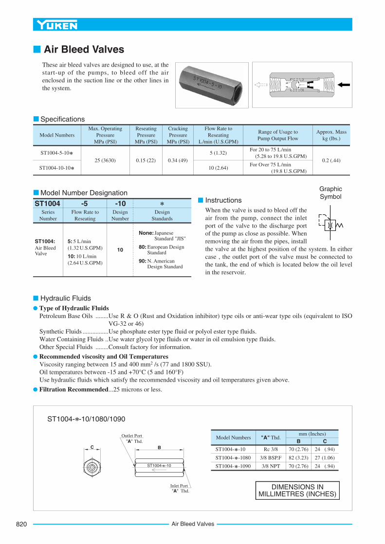
■ Air Bleed ValvesThese air bleed valves are designed to use, at thestart-up of the pumps, to bleed off the airenclosed in the suction line or the other lines inthe system.
Max. Operating Pressure
MPa (PSI)Model Numbers
Approx. Mass kg (lbs.)
CrackingPressure
MPa (PSI)
ReseatingPressure
MPa (PSI)
Flow Rate to Reseating
L/min (U.S.GPM)
Range of Usage to Pump Output Flow
ST1004-5-10
ST1004-10-10
25 (3630) 0.15 (22) 0.34 (49)
5 (1.32)
10 (2.64)
0.2 (.44)
For 20 to 75 L /min (5.28 to 19.8 U.S.GPM)
For Over 75 L /min (19.8 U.S.GPM)
Specifications
SeriesNumber
Flow Rate to Reseating
DesignNumber
DesignStandards
ST1004 -5 -10
10
None:JapaneseStandard "JIS"
80: European Design Standard
90: N. American Design Standard
ST1004:Air Bleed Valve
5: 5 L /min
10: 10 L /min
(1.32 U.S.GPM)
(2.64 U.S.GPM)
Model Number Designation■ Instructions
When the valve is used to bleed off theair from the pump, connect the inletport of the valve to the discharge portof the pump as close as possible. Whenremoving the air from the pipes, installthe valve at the highest position of the system. In eithercase , the outlet port of the valve must be connected tothe tank, the end of which is located below the oil levelin the reservoir.
GraphicSymbol
■ Hydraulic Fluids ● Type of Hydraulic Fluids
Petroleum Base Oils ........Use R & O (Rust and Oxidation inhibitor) type oils or anti-wear type oils (equivalent to ISOVG-32 or 46)
Synthetic Fluids ................Use phosphate ester type fluid or polyol ester type fluids.Water Containing Fluids ..Use water glycol type fluids or water in oil emulsion type fluids.Other Special Fluids ........Consult factory for information.
● Recommended viscosity and Oil TemperaturesViscosity ranging between 15 and 400 mm2 /s (77 and 1800 SSU).Oil temperatures between -15 and +70°C (5 and 160°F)Use hydraulic fluids which satisfy the recommended viscosity and oil temperatures given above.
● Filtration Recommended...25 microns or less.
ST1004- -10
ST1004- -1080
ST1004- -1090
Model Numbers "A" Thd.B
70 (2.76)
82 (3.23)
70 (2.76)
Rc 3/8
3/8 BSP.F
3/8 NPT
Cmm (Inches)
24
27
24
(.94)
(1.06)
(.94)
DIMENSIONS IN MILLIMETRES (INCHES)
ST1004- -10
Outlet Port "A" Thd.
C B
Inlet Port "A" Thd.
ST1004- -10/1080/1090

821
ACCESSORIES
Acc
esso
ries
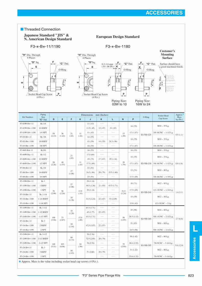
“F3” Series Pipe Flange Kits
L
■ “F3” Series Pipe Flange Kits■ Specifications● Max. Operating Pressure...25 MPa (3630 PSI)
ThreadedConnection
SocketWelding
FlangeSize
DesignNumber
DesignStandards
-11
11
None:Japanese Standard "JIS" & European Design Standard
90:N. American Design Standard
None:Japanese Standard "JIS"
90:N. American Design Standard
80:European Design Standard
11
-N-A-03WF3F-Materialof Seal
SeriesNumber
Type of Pipe Connection
O-Ring & Bolts
F3
None:Standard NBR (Buna N) Seal
F:FPM (Viton) Seal (For Synthetic fluids)
A:Pipe Socket Welding
C:Block Type
B:ThreadedConnection
None:With O-Ring and Mounting Bolts
N:No O-Ring and Mounting Bolts
None:With O-Ring and Mounting Bolts
N:No O-Ring and Mounting Bolts
03W, 03, 06V
06W, 06, 10W
10, 16W, 16
24W, 24
03W, 03, 06W
06, 10W, 10
16W, 16, 24W
24
03W, 03, 06W
06, 10W, 10
16W, 16, 24W
24
03W, 03, 06V
06W, 06, 10W
10, 16W, 16
24W, 24
Type of Pipe Connection
DesignStandard
PipeThread
Mounting Bolt (Socket Head Cap Screw)
Pipe Socket Welding Block Type
Threaded Connection
Rc
BSP.F
NPT
Unified Thd.
Metric Thd.
Metric Thd.
Unified Thd.
Metric Thd.Japanese Standard "JIS" & European Design Standard
N. American Design Standard
Japanese Standard "JIS"
European Design Standard
N. American Design Standard
Model Number Designation
Three different design standards are available as shown blow. Select the suitable design standard to your requirement.

“F3” Series Pipe Flange Kits822
O-Ring O-Ring
Surface should have a good machined finish.
"H" Dia. Through 4 Places
Soc. Hd. Cap Screw (4 Pcs.)
"N"
Dia
. Max
.
"K" D
ia.
"J"
Dia
.
P
FF
LE
"D" Sq.
P
E
Customer’s Mounting Surface
Pipe Socket Welding Block Type
F3- -A -11/1190 F3- -C -11/1190
14(.55)17.1(.67)14
(.55)17.1(.67)
18(.71)17.5(.69)
14(.55)17.1(.67)
14(.55)
14(.55)17.1(.67)
18(.71)17.5(.69)25
(.98)22.1(.87)25
(.98)22.1(.87)36
(1.42)38.6
(1.52)36
(1.42)38.6
(1.52)
M10 35 Lg.
3/8-16UNC 1-1/2 Lg.
M10 35 Lg.
3/8-16UNC 1-1/2 Lg.
M22 80 Lg.
7/8-9UNC 3-1/4 Lg.
M22 80 Lg.
7/8-9UNC 3-1/4 Lg.
M16 60 Lg.
8/5-11UNC 2-1/4 Lg.
M16 60 Lg.
8/5-11UNC 2-1/4 Lg.
M12 45 Lg.
1/2-13UNC 1-3/4 Lg.
M12 45 Lg.
1/2-13UNC 1-3/4 Lg.
M10 35 Lg.
M10 35 Lg.
3/8-16UNC 1-1/2 Lg.
M10 35 Lg.
3/8-16UNC 1-1/2 Lg.
1.4 (3.1)
2.7 (6.0)
5.8 (12.8)
0.8 (1.8)
0.5 (1.1)SO-NB-G25
Approx.Mass
kg (lbs.)
Socket Head Cap Screw
O-RingDimensions mm (Inches)Piping
SizeKit Numbers
D E F H J K L N P
SO-NB-G30
SO-NB-G40
SO-NB-G60
SO-NB-G85
F3-03W- -11
F3-03W- -1190
F3-03- -11
F3-03- -1190
F3-10W- -11
F3-10W- -1190
F3-10- -11
F3-10- -1190
F3-16W- -11
F3-16W- -1190
F3-16- -11
F3-16- -1190
F3-24W- -11
F3-24W- -1190
F3-24- -11
F3-24- -1190
F3-06V- -11
F3-06W- -11
F3-06W- -1190
F3-06- -11
F3-06- -1190
1/4
3/8
1
1-1/4
1-1/2
2
2-1/2
3
54(2.13)
58(2.28)
76(2.99)
100(3.94)
140(5.51)
36(1.42)
40(1.57)
56(2.20)
73(2.87)
103(4.06)
21(.83)
21(.83)
27(1.06)
35(1.38)
14.3(.56)
11(.43)
13.5(.53)
17.5(.69)
15(.59)
20(.79)
31.5(1.24)
50(1.97)
44(1.73)
24(.94)
75(2.95)
1/2
3/4
3/8
11(.43)
11(.43)
8(.31)
17.8(.70)
12.5(.49)
9(.35)
22.2(.87)
16(.63)
11(.43)
27.7(1.09)
20(.79)
12(.47)
34.5(1.36)
25(.98)
14(.55)
16(.63)
49.1(1.93)
37.5(1.48)
18(.71)
61.1(2.41)
47.5(1.87)
20(.79)
77.1(3.04)
60(2.36)
22(.87)
90.0(3.54)
71(2.80)
25(.98)
17.8(.70)
12.5(.49)
9(.35)
43.2(1.70)
31.5(1.24)
Approx. mass is the value including socket head cap screws (4 Pcs.).
823
ACCESSORIES
Acc
esso
ries
L
“F3” Series Pipe Flange Kits
O-Ring
"H" Dia. Through 4 Places
Socket Head Cap Screw (4 Pcs.)
"J" D
ia.
F
E
"D" Sq.
P
E
"H" Dia. Through 4 Places
"D"Sq.
E"C" Thd.
Socket Head Cap Screw (4 Pcs.)
E
"L"
Dia
.
K
F
O-Ring
"C" Thd.
"J" D
ia.
P P
O-Ring
"C" Thd.K
F
"J" D
ia.
Surface should have a good machined finish.
"N" D
ia. M
ax.
0.3-1.6 mm (.01-.06 IN.)
Customer’sMountingSurface
Piping Size: 03W to 10
Piping Size: 16W to 24
Threaded Connection
F3- -B -3F0911/11- -B -1180
Japanese Standard "JIS" & N. American Design Standard
European Design Standard
Approx.Mass
kg (lbs.)
Socket Head Cap Screw
O-RingDimensions mm (Inches)Piping
Size"C" Thd.
Kit NumbersD E F H J K L N P
11 (.43)
11.5 (.45)
11 (.43)
14 (.55)
15 (.59)
14 (.55)
14 (.55)
17.5 (69)
19 (.75)
17.5 (.69)
23 (.91)
24.5 (.96)
23 (.91)
29 (1.14)
30.5 (1.20)
29 (1.14)
Rc 1/4
1/4 BSP.F
1/4 NPT
Rc 3/8
3/8 BSP.F
3/8 NPT
F3-03W-B -11
F3-03W-B -1180
F3-03W-B -1190
F3-03-B -11
F3-03-B -1180
F3-03-B -1190 3/8-16UNC 1-1/2 Lg.
SO-NB-G25
5.8 (12.8)
3/8-16UNC 1-1/2 Lg.
3/8-16UNC 1-1/2 Lg.
3/8-16UNC 1-3/4 Lg.
1/2-13UNC 1-3/4 Lg.
1/2-13UNC 2 Lg.
5/8-11UNC 2-1/2 Lg.
5/8-11UNC 2-1/2 Lg.
7/8-9UNC 3-1/4 Lg.
7/8-9UNC 3-1/4 Lg.
M10 35 Lg.
M10 35 Lg.
M10 35 Lg.
M10 35 Lg.
M10 40 Lg.
M12 45 Lg.
M12 50 Lg.
M16 60 Lg.
M16 60 Lg.
M22 80 Lg.
M22 80 Lg.
2.7 (6.0)
1.4 (3.1)
0.8 (1.8)
0.5 (1.1)
SO-NB-G30
SO-NB-G40
SO-NB-G60
SO-NB-G85
14 (.55)
14 (.55)
14 (.55)
13 (.51)
18 (.71)
15 (.59)
25 (.98)
21 (.83)
36 (1.42)
31 (1.22)
33.6 (1.32)
38.6 (1.52)
24.5 (.96)
28.5 (1.12)
15.8 (.62)
17.5 (.69)
17.5 (.69)
17.1 (.67)
14 (.55)
17.1 (.67)
17.1 (.67)
43.5 (1.71)
45 (1.77)
43.5 (1.71)
47.5 (1.87)
70 (2.76)
72.5 (2.85)
70 (2.76)
71 (2.80)
75(2.95)
50(1.97)
31.5(1.24)
20(.79)
15(.59)
12 (.47)
14 (.55)
17 (.67)
20 (.79)
21 (.83)
22 (.87)
22 (.87)
22 (.87)
20 (.79)
20 (.79)
24.3 (.96)
29 (1.14)
21 (.83)
35.5 (1.40)
43.5 (1.71)
53 (2.09)
54(2.13)
36(1.42)
21(.83)
11(.43)
31.5 (1.24)
58(2.28)
56(2.20)
13.5(.53)
73(2.87)
17.5(.69)
103(4.06)
24(.94)
40(1.57)
27(1.06)
11(.43)
76(2.99)
100(3.94)
140(5.51)
21(.83)
27(1.06)
35(1.38)
35(1.28)
39(1.54)
44(1.73)
49(1.93)
Rc3/8
Rc 1/2
1/2 BSP.F
1/2 NPT
Rc 3/4
3/4 BSP.F
3/4 NPT
Rc 1
1 BSP.F
1 NPT
Rc 1-1/4
1-1/4 BSP.F
1-1/4 NPT
Rc 1-1/2
1-1/2 BSP.F
1-1/2 NPT
Rc 2
2 BSP.F
2 NPT
Rc 2-1/2
2-1/2 BSP.F
2-1/2 NPT
Rc 3
3 BSP.F
3 NPT
F3-10W-B -11
F3-10W-B -1180
F3-10W-B -1190
F3-10-B -11
F3-10-B -1180
F3-10-B -1190
F3-16W-B -11
F3-16W-B -1180
F3-16W-B -1190
F3-16-B -11
F3-16-B -1180
F3-16-B -1190
F3-24W-B -11
F3-24W-B -1180
F3-24W-B -1190
F3-24-B -11
F3-24-B -1180
F3-24-B -1190
F3-06V-B -11
F3-06W-B -11
F3-06W-B -1180
F3-06W-B -1190
F3-06-B -11
F3-06-B -1180
F3-06-B -1190
Approx. Mass is the value including socket head cap screws (4 Pcs.).
“F5” Series Pipe Flange Kits824
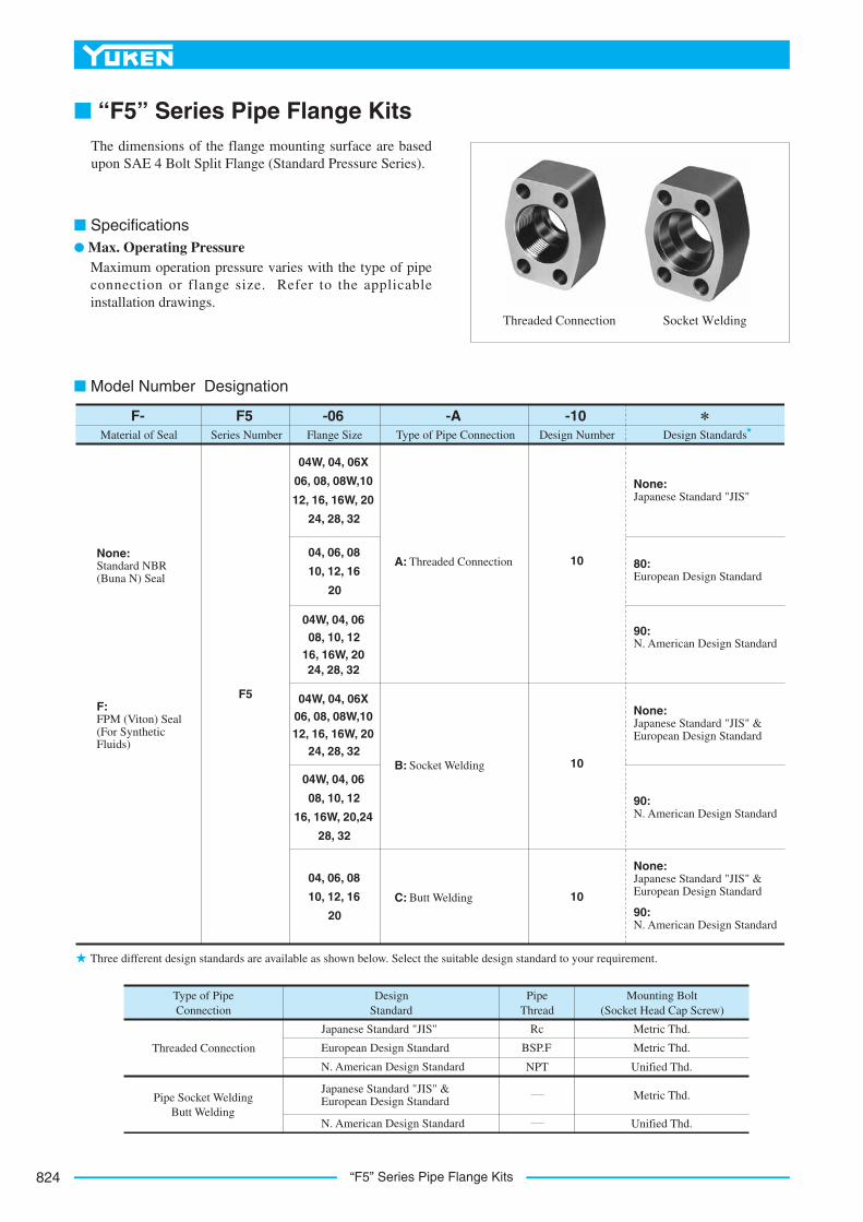
■ “F5” Series Pipe Flange Kits
■ Specifications● Max. Operating Pressure
Maximum operation pressure varies with the type of pipeconnection or flange size. Refer to the applicableinstallation drawings.
The dimensions of the flange mounting surface are basedupon SAE 4 Bolt Split Flange (Standard Pressure Series).
Threaded Connection Socket Welding
sdradnatS ngiseDrebmuN ngiseDeziS egnalF
-10-A-06F5F-Material of Seal Series Number Type of Pipe Connection
10
None:Japanese Standard "JIS"
90:N. American Design Standard
None:Japanese Standard "JIS" & European Design Standard
80:European Design Standard
F5
None:Standard NBR (Buna N) Seal
F:FPM (Viton) Seal (For Synthetic Fluids)
B: Socket Welding
04W, 04, 06X
06, 08, 08W,10
12, 16, 16W, 20
24, 28, 32
04, 06, 08
10, 12, 16
20
04W, 04, 06 08, 10, 12
16, 16W, 20
04W, 04, 06X 06, 08, 08W,10 12, 16, 16W, 20
24, 28, 32
24, 28, 32
04W, 04, 06
08, 10, 12
16, 16W, 20,24
28, 32
04, 06, 08
10, 12, 16
20
10
10
90:N. American Design Standard
None:Japanese Standard "JIS" & European Design Standard
90:N. American Design Standard
C: Butt Welding
A: Threaded Connection
Type of Pipe Connection
DesignStandard
PipeThread
Mounting Bolt (Socket Head Cap Screw)
Pipe Socket Welding Butt Welding
Threaded Connection
Rc
BSP.F
NPT
Metric Thd.
Metric Thd.
Unified Thd.
Metric Thd.Japanese Standard "JIS" & European Design Standard
N. American Design Standard
Japanese Standard "JIS"
European Design Standard
N. American Design Standard
Unified Thd.
Three different design standards are available as shown below. Select the suitable design standard to your requirement.
■ Model Number Designation

825
ACCESSORIES
Acc
esso
ries
L
“F5” Series Pipe Flange Kits
"J" Dia. Through 4 Places
DE
L
Surface should have a good machined finished.
"N" D
ia. M
ax.
FH
K
O-Ring
"C" Thd.
Soc. Hd Cap Screw (4 Pcs.)
Customer’sMounting Surface
Japanese Standard "JIS" N. American Design Standard
: F5- -A-10 : F5- -A-1090
Threaded Connection
21
1.2.
Approx.Mass
kg (lbs.)
Socket Head Cap Screw
(4 Pcs.)O-Ring
Max. Operating Pressure
MPa (PSI)
RecommendedTightening
Torque(Tolerance ±10%)
Nm (IN.lbs.)
M8 45 Lg.
M10 45 Lg.
3/8-16UNC 1-3/4 Lg.
SO-NB-G85
SO-NB-G100
SO-NB-G115
PipingSize
"C" Thd.
KitNumbers
Rc 3/8
Rc 1/2
3/8 NPT
1/2 NPT
F5-04W-A-10
F5-04-A-1038.1
(1.500)
10(.39)
13(.51)
30(1.18)
8.8(.346)
Rc 3/4
3/4 NPT
Rc 3/4
Rc 1
1 NPT
Rc 1-1/4
1-1/4 NPT
Rc 1-1/2
1-1/2 NPT
Rc 1-1/2
Rc 2
1-1/2 NPT
2 NPT
Rc 2-1/2
2-1/2 NPT
Rc 3
3 NPT
4 NPT
3-1/2 NPT
Rc 3-1/2
Rc 4
F5-04W-A-1090
F5-04-A-1090
F5-06X-A-10
F5-06-A-10
F5-06-A-1090
F5-08W-A-10
F5-08-A-10
F5-08-A-1090
F5-10-A-10
F5-10-A-1090
F5-12-A-10
F5-12-A-1090
F5-16W-A-1090
F5-16-A-1090
F5-16W-A-10
F5-16-A-10
F5-20-A-10
F5-20-A-1090
F5-24-A-10
F5-24-A-1090
F5-28-A-10
F5-28-A-1090
F5-32-A-10
F5-32-A-1090
SO-NB-G60
SO-NB-G65
SO-NB-G60
SO-NB-G65
SO-NB-G50
SO-NB-G40
SO-NB-G35
SO-NB-G30
SO-NB-P22
SO-NB-G75
28(4060)
0.5(1.1)
35(310)
35(310)
68.5(606)
68.5(606)
68.5(606)
118(1044)
118(1044)
118(1044)
287(2540)
0.7(1.5)
0.9(2.0)
1.2(2.6)
1.5(3.3)
1.8(4.0)
1.7(3.8)
1.8(4.0)
1.7(3.8)
2.0(4.4)
2.7(6.0)
3.4(7.5)
3.7(8.2)
21(3050)
17.5(2540)
21(3050)
17.5(2540)
17.5(2540)
3.5(510)
21(3050)
17.5(.689)
40(1.57)
14.5(.57)
47.6(1.874)
22.2(.874)
48(1.89)
55(2.17)
64(2.52)
72(2.83)
85(3.35)
102(4.02)
116(4.57)
134(5.28)
150(5.91)
114(4.49)
13.5(.531)
26.2(1.031)
52.4(2.063)
30.2(1.189)
58.7(2.311)
35.7(1.406)
69.9(2.752)
42.9(1.689)
77.8(3.063)
61.9(2.437)
69.9(2.752)
77.8(3.068)
50.8(2.000)
88.9(3.500)
17.5(.689)
53(2.09)
17(.67)19.2(.76)
19.2(.76)
19.2(.76)
17(.67)
17(.67)
76(2.99)
88(3.46)
101(3.98)
48(1.89)
63(2.48)21.8
(.86)
17(.67)
51(2.01)
48(1.89)
51(2.01)
48(1.89)
38(1.50)
32(1.26)
26(1.02)
19(.75)
30(1.18)11
(.433)
8.8(.346)
14.5(.57)
15(.59)
30(1.18)
38(1.50)
38(1.50)
38(1.50)
13.5(.531)
13.5(.531)
12(.472)
11(.433)
11(.433)
14.5(.57)
15(.59)
17(.67)
19.2(.76)
17(.67)
19.2(.76)
17(.67)
19.2(.76)
M8 40 Lg.
5/16-18UNC 1-3/4 Lg.
M10 45 Lg.
3/8-16UNC 1-3/4 Lg.
M10 55 Lg.
7/16-14UNC 2-1/4 Lg.
M12 55 Lg.
1/2-13UNC 2-1/4 Lg.
M12 55 Lg.
1/2-13UNC 2-1/4 Lg.
M12 65 Lg.
1/2-13UNC 2-3/4 Lg.
M16
5/8-11UNC x 2-3/4 Lg.
5/8-11UNC x 2-3/4 Lg.
5/8-11UNC x 2-3/4 Lg.
70 Lg.
M16 70 Lg.
M16 70 Lg.
28(4060)
28(4060)
28(4060)
135(5.31)
153(6.02)
162(6.38)
70(2.76)
80(3.15)
94(3.70)
102(4.02)
54(2.13)
65(2.56)
106.4(4.189)
120.7(4.752)
130.2(5.126)
Dimensions mm (Inches)
D E F J K L NH
Approx. mass is the value including socket head cap screws (4 Pcs.).The values of recommended tightening torque are for socket head cap screws and apply to when these flanges are used for pressure line.

“F5” Series Pipe Flange Kits826
"J" Dia. Through "K" C' bore "P" Deep 4 Places
D
E
N
Surface should have a good machine finish.
"S"
Dia
. Max
.
F
H
L
O-Ring
"C" Thd.
Socket Head Cap Screw (4 Pcs.)
N
Q0.3-0.5 mm(.01-.02 IN.)
K
Q
Customer’sMounting Surface
European Design Standard F5- -A-1180
Piping Size:1/2 to 1-1/2
Piping Size:2 & 2-1/2
Threaded Connection
PipingSize
"C" Thd.
KitNumbers
Dimensions mm (Inches)
D E F J K L NH
F5-04-A-1080
F5-06-A-1080
F5-08-A-1080
F5-10-A-1080
F5-12-A-1080
F5-16-A-1080
F5-20-A-1080
1/2 BSP.F
3/4 BSP.F
1 BSP.F
1-1/4 BSP.F
1-1/2 BSP.F
2 BSP.F
2-1/2 BSP.F
40(1.57)
59(2.32)
17.5(.689)
38.1(1.500)
8.8(.346)
14(.55)
31(1.22)
12.6(.50)
8.6(.34)
17(.67)
15(.59)
Socket Head Cap Screw
(4 Pcs.)
M8 35 Lg.
M10 35 Lg.
M10 35 Lg.
M10 45 Lg.
M12 45 Lg.
M12 45 Lg.
M12 50 Lg.
SO-NB-P22
SO-NB-G30
SO-NB-G35
SO-NB-G40
SO-NB-G50
SO-NB-G65
SO-NB-G75
Approx.Mass
kg(lbs.)
O-Ring
0.5(1.1)
Max.OperatingPressure
MPa(PSI)P Q S
28(4060)
0.7(1.5)
0.9(2.0)
1.2(2.6)
21(3050)
1.6(3.5)
17.5(2540)
1.8(4.0)
17.5(2540)
1.9(4.2)
48(1.89)
72(2.83)
22.2(.874)
47.6(1.874)
11(.433)
17.5(.69)
31(1.22)
14.8(.58)
10.8(.43)
20(.79)
19(.75)
55(2.17)
77(3.03)
26.2(1.031)
52.4(2.063)
11(.433)
17.5(.69)
31(1.22)
14.8(.58)
10.8(.43)
21(.83)
25(.98)
64(2.52)
83(3.27)
30.2(1.189)
58.7(2.311)
11(.433)
17.5(.69)
39(1.54)
16.8(.66)
10.8(.43)
22(.87)
32(1.26)
72(2.83)
99(3.90)
35.7(1.406)
69.9(2.752)
13.5(.531)
21(.83)
41(1.61)
17.5(.69)
13.5(.53)
38(1.50)
85(3.35)
107(4.21)
42.9(1.689)
77.8(3.063)
13.5(.531)
21(.83)
41(1.61)
17.5(.69)
50(1.97)
102(4.02)
118(4.65)
50.8(2.000)
88.9(3.500)
13.5(.531)
21(.83)
46(1.81)
17.5(.69)
31(1.22)
63(2.48)
31(1.22)
22(.87)
13.5(.53)
13.5(.53)
28(4060)
28(4060)
28(4060)
F5-04-A-1080
F5-06-A-1080
F5-08-A-1080
F5-10-A-1080
F5-12-A-1080
F5-16-A-1080
F5-20-A-1080
Kit NumbersRecommendation Nm (IN.lbs.) Tolerance
Tightening Torque
35 (310)
68.5 (606)
118 (1044)
±10%
Approx. mass is the value including socket head cap screws (4 Pcs.).
Note: The values of tightening torque above apply to when these flanges are used for pressure line.
euqroT gninethgiT dednemmoceRFor Socket Head Cap Screw

827
ACCESSORIES
Acc
esso
ries
L
“F5” Series Pipe Flange Kits
"J" Dia. Through 4 Places
D
Socket Head Cap Screw (4 Pcs.)
E
L
Surface should have a good machined finish.
"S"
Dia
. Max
.
F
H
Q
K
O-Ring"N
" D
ia.
Customer’sMountingSurface
Japanese Standard "JIS" & European Design Standard : F5- -B-10N. American Design Standard : F5- -B-1090
Socket Welding
F5-04W-BF5-04-BF5-06X-BF5-06-BF5-08W-BF5-08-BF5-10-BF5-12-BF5-16W-BF5-16-BF5-20-BF5-24-BF5-28-BF5-32-B
Kit Numbers RecommendationNm (IN.lbs.)
Tolerance
Tightening Torque
35 (310)
68.5 (660)
118 (1044)
287 (2540)
±10%
Recommended Tightening Torque For Socket Head Cap Screw
Note: The values of tightening torque above apply to when these flanges are used for pressure line.
Approx.Mass
kg (lbs.)
Socket Head Cap Screw
(4 Pcs.)O-Ring
Dimensions mm (Inches)PipingSize
Kit Numbers
D E F J K L N
10(.39)
SO-NB-P22
M8 40 Lg.
5/16-18UNC 1-3/4 Lg.
M8 40 Lg.
5/16-18UNC 1-3/4 Lg.
M8 45 Lg.
M10 45 Lg.
3/8-16UNC 1-3/4 Lg.
28(4060)
Max. Operating Pressure
MPa(PSI)
14.5(.57)
10(.39)
14.5(.57)
15(.59)
15(.59)
14.5(.57)
14.5(.57)
17(.67)
19.2(.76)
17(.67)
19.2(.76)
17(.67)
19.2(.76)
17(.67)
19.2(.76)
17(.67)
21.8(.86)
17(.67)
19.2(.76)
17(.67)
19.2(.76)
17(.67)
19.2(.76)
3/8
M10 45 Lg.
3/8-16UNC 1-3/4 Lg.
M10 55 Lg.
7/16-14UNC 2-1/4 Lg.
M12 55 Lg.
1/2-13UNC 2-1/4 Lg.
M12 55 Lg.
1/2-13UNC 2-1/4 Lg.
M12 55 Lg.
1/2-13UNC 2-1/4 Lg.
M12 65 Lg.
1/2-13UNC 2-3/4 Lg.
M16 55 Lg.
5/8-11UNC 2-1/4 Lg.
M16 55 Lg.
5/8-11UNC 2-1/4 Lg.
M16 55 Lg.
5/8-11UNC 2-1/4 Lg.
SO-NB-G100
SO-NB-G115
SO-NB-G85
SO-NB-G75
SO-NB-G65
SO-NB-G60
SO-NB-G50
SO-NB-G40
SO-NB-G35
SO-NB-G30
28(4060)
14(2030)
28(4060)
14(2030)
14(2030)
14(2030)
21(3050)
10.5(1520)
7(1020)
3.5(510)
3.5(510)
3.5(510)
0.5(1.1)
0.7(1.5)
0.9(2.0)
1.2(2.7)
1.5(3.3)
1.8(3.7)
1.7(3.8)
2.0(4.4)
2.7(6.0)
3.4(7.5)
3.7(8.2)
48(1.89)
51(2.01)
63(2.48)
76(2.99)
88(3.46)
101(3.98)
38(1.50)
32(1.26)
26(1.02)
19(.75)
13(.51)
30(1.18)
8.8(.346)
38.1(1.500)
17.5(.689)
54(2.13)
40(1.57)
17.8(.701)
9(.35)
22.2(.874)
11(.43)
27.7(1.091)
12(.47)
30(1.18)
47.6(1.874)
22.2(.874)
65(2.56)
48(1.89)
30(1.18)
11(.433)
52.4(2.063)
26.2(1.031)
70(2.76)
55(2.17)
16(.63)
43.2(1.701)
38(1.50)
11(.433)58.7
(2.311)30.2
(1.189)80
(3.15)64
(2.52)
18(.71)
49.1(1.933)
38(1.50)
13.5(.531)
18(.71)
49.1(1.933)
20(.79)
61.1(2.406)
38(1.50)
77.8(3.063)
42.9(1.689)
102(4.02)
85(3.35)
22(.87)
77.1(3.035)
48(1.89)
88.9(3.500)
50.8(2.000)
114(4.49)
102(4.02)
25(.98)
90.0(3.543)
38(1.50)
13.5(.531)
106.4(4.189)
61.9(2.437)
135(5.31)
116(4.57)
28(1.10)
102.8(4.047)
38(1.50)
17.5(.689)
120.7(4.752)
69.9(2.752)
153(6.02)
134(5.28)
31.5(1.24)
115.5(4.547)
38(1.50)
17.5(.689)
130.2(5.126)
77.8(2.063)
162(6.38)
150(5.91)
14(.55)
34.5(1.358)
27.7(1.091)
12(.47)
11(.433)
8.8(.346)
Q SH
17.5(.689)
13.5(.531)
1/2
3/4
3/4
1
1-1/4
1-1/2
1-1/2
2
2-1/2
3
3-1/2
4
F5-04W-B-10
F5-04W-B-1090
F5-04-B-10
F5-04-B-1090
F5-06X-B-10
F5-06-B-10
F5-06-B-1090
F5-08W-B-10
F5-08-B-10
F5-08-B-1090
F5-10-B-10
F5-10-B-1090
F5-12-B-10
F5-12-B-1090
F5-16W-B-10
F5-16W-B-1090
F5-16-B-10
F5-16-B-1090
F5-20-B-10
F5-20-B-1090
F5-24-B-10
F5-24-B-1090
F5-28-B-10
F5-28-B-1090
F5-32-B-10
F5-32-B-1090
12(.472)
69.9(2.752)
35.7(1.406)
94(3.70)
72(2.83)
Approx. mass is the value including socket head cap screws (4 Pcs.).
“F5” Series Pipe Flange Kits828
"J" Dia. Through 4 Places
D
E
L
Surface should have a good machined finish.
"Q"
Dia
.
F
H
O-Ring
Socket Head Cap Screw (4 Pcs.)
K
N
"S" D
ia. M
ax.
Customer’sMounting Surface
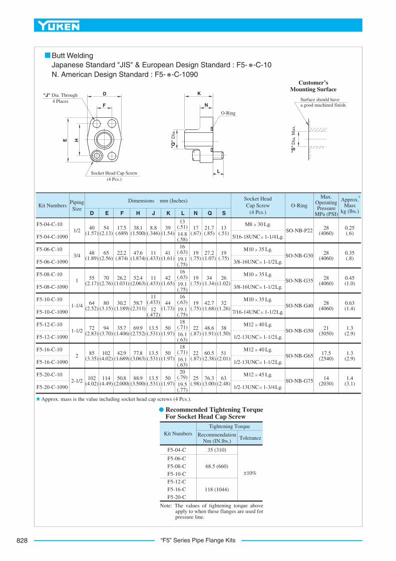
Japanese Standard "JIS" & European Design Standard : F5- -C-10N. American Design Standard : F5- -C-1090
Butt Welding
M8 30 Lg.
5/16-18UNC 1-1/4 Lg.SO-NB-P22
SO-NB-G30
SO-NB-G35
SO-NB-G40
SO-NB-G50
SO-NB-G65
SO-NB-G75
Approx.Mass
kg (lbs.)
Socket Head Cap Screw
(4 Pcs.)O-Ring
Max.OperatingPressure
MPa (PSI)
PipingSize
Kit Numbers
F5-04-C-10
F5-04-C-1090
13(.51)
Dimensions mm (Inches)
D E F H J K L N Q S
1/2
3/4
1
1-1/4
1-1/2
2
2-1/2
19(.75)
26(1.02)
32(1.26)
38(1.50)
51(2.01)
63(2.48)
M10 35 Lg.
3/8-16UNC 1-1/2 Lg.
M10 35 Lg.
3/8-16UNC 1-1/2 Lg.
M10 35 Lg.
7/16-14UNC 1-1/2 Lg.
M12 40 Lg.
1/2-13UNC 1-1/2 Lg.
M12 40 Lg.
1/2-13UNC 1-1/2 Lg.
M12 45 Lg.
1/2-13UNC 1-3/4 Lg.
28(4060)
28(4060)
28(4060)
28(4060)
21(3050)
17.5(2540)
14(2030)
0.25(.6)
0.35(.8)
0.45(1.0)
0.63(1.4)
1.3(2.9)
1.3(2.9)
1.4(3.1)
21.7(.85)
27.2(1.07)
34(1.34)
42.7(1.68)
48.6(1.91)
60.5(2.38)
76.3(3.00)
17(.67)
39(1.54)
41(1.61)
42(1.65)
44(1.73)
50(1.97)
50(1.97)
50(1.97)
8.8(.346)
11(.433)
11(.433)
13.5(.531)
13.5(.531)
13.5(.531)
38.1 (1.500)
54(2.13)
65(2.56)
70(2.76)
80(3.15)
94(3.70)
114(4.49)
40(1.57)
48(1.89)
55(2.17)
64(2.52)
72(2.83)
85(3.35)
102(4.02)
17.5 (.689)
13(.51)14.8(.58)16
(.63)19.1(.75)16
(.63)19.1(.75)16
(.63)19.1(.75)18
(.71)
18(.71)
20(.79)19.5(.77)
11(.433)
12(.472)
47.6 (1.874)
22.2 (.874)
52.4 (2.063)
26.2 (1.031)
58.7 (2.311)
30.2 (1.189)
69.9 (2.752)
35.7 (1.406)
77.8 (3.063)
42.9 (1.689)
88.9 (3.500)
50.8 (2.000)
19(.75)
19(.75)
19(.75)
22(.87)
22(.87)
25(.98)
F5-06-C-10
F5-06-C-1090
F5-08-C-10
F5-08-C-1090
F5-10-C-10
F5-10-C-1090
F5-12-C-10
F5-12-C-1090
F5-16-C-10
F5-16-C-1090
F5-20-C-10
F5-20-C-1090
F5-04-C
F5-06-C
F5-08-C
F5-10-C
Kit Numbers RecommendationNm (IN.lbs.)
Tolerance
Tightening Torque
35 (310)
68.5 (660)
118 (1044)
±10%
F5-12-C
F5-16-C
F5-20-C
102(4.02)
16.1(.63)
16.1(.63)
Approx. mass is the value including socket head cap screws (4 Pcs.).
Recommended Tightening Torque For Socket Head Cap Screw
Note: The values of tightening torque above apply to when these flanges are used for pressure line.

829
ACCESSORIES
Acc
esso
ries
L
“F6” Series Pipe Flange Kits
■ “F6” Series Pipe Flange Kits
■ Specifications
The dimensions of the flange mounting surface are basedupon SAE 4 Bolt Split Flange (High Pressure Series).
Threaded Connection Socket Welding
Model NumbersMax. Operating
PressureMPa (PSI)
Remarks
Threaded Connection
Pipe Socket Welding
31 (4500)
42 (6090)
F6- -A- -10/1080/1090
F6- -B- -10/1090
FlangeSize
DesignNumber
DesignStandards
-10
10
None:Japanese Standard "JIS"
90:N. American Design Standard
None:Japanese Standard "JIS" & European Design Standard
90:N. American Design Standard
80:European Design Standard
10
-M-A-06F6F-Materialof Seal
SeriesNumber
Type of Pipe Connection
Type of Mounting Bolt
F6
None:Standard NBR (Buna N) Seal
F:FPM (Viton) Seal (For Synthetic Fluids)
B:Pipe Socket Welding
A:ThreadedConnection
04W, 04 06W, 06 08W, 08 10W, 10 12W, 12
04W, 04 06W, 06 08W, 08 10W, 10 12W, 12
04W, 04 06W, 06 08W, 08 10W, 10 12W, 12
04W, 04 06W, 06 08W, 08 10W, 10 12W, 12
04W, 04 06W, 06 08W, 08 10W, 10 12W, 12
M: Metric Thd.
M: Metric Thd.
U: Unified Thd.
M: Metric Thd.
U: Unified Thd.
Type of Pipe Connection
DesignStandard
PipeThread
Mounting Bolt (Socket Head Cap Screw)
Pipe Socket Welding
Threaded Connection
Rc
BSP.F
NPT
Metric Thd.
Metric Thd.
Unified Thd.
Metric Thd.Japanese Standard "JIS" & European Design Standard
N. American Design Standard
Japanese Standard "JIS"
European Design Standard
N. American Design Standard
Unified Thd.
Three different design standards are available as shown below. Select the suitable design standard to your requirement.
■ Model Number Designation

“F6” Series Pipe Flange Kits830
Surface should have a good machined finish.
"N"
Dia
. Max
.
"J" Dia. Through 4 Places
D
E
L
F
H
K
O-Ring
"C" Thd.
Soc. Head Cap Screw (4 Pcs.)
Customer’sMounting Surface
Japanese Standard "JIS" N. American Design Standard
: F6- -A-M-10 : F6- -A-U-1090
■ Threaded Connection
1.
2.
21
Approx.Mass
kg (lbs.)
Socket Head Cap Screw
(4 Pcs.)O-Ring
RecommendedTightening
Torque(Tolerance ±10%)
Nm (IN.lbs.)
PipingSize
"C" Thd.
KitNumbers
Dimensions mm (Inches)
D E F J L N
Rc 3/8
Rc 1/2
3/8 NPT
1/2 NPT
F6-04W-A-M-10
F6-04-A-M-10
F6-04W-A-U-1090
F6-04-A-U-1090
SO-NB-P22
SO-NB-G30
SO-NB-G35
SO-NB-G40
SO-NB-G50
0.4(.9)
35(310)
H
5/16-18UNC 1-1/2 Lg.
K
F6-06W-A-M-10
F6-06-A-M-10
F6-06W-A-U-1090
F6-06-A-U-1090
F6-08W-A-M-10
F6-08-A-M-10
F6-08W-A-U-1090
F6-08-A-U-1090
F6-10W-A-M-10
F6-10-A-M-10
F6-10W-A-U-1090
F6-10-A-U-1090
F6-12W-A-M-10
F6-12-A-M-10
F6-12W-A-U-1090
F6-12-A-U-1090
Rc 1/2
Rc 3/4
1/2 NPT
3/4 NPT
Rc 3/4
Rc 1
3/4 NPT
1 NPT
Rc 1
Rc 1-1/4
1 NPT
1-1/4 NPT
Rc 1-1/4
Rc 1-1/2
1-1/4 NPT
1-1/2 NPT
3/8-16UNC 1-3/4 Lg.
M12 45 Lg.
M12 50 Lg.
7/16-14UNC 1-3/4 Lg.
7/16-14UNC 2 Lg.
M12 50 Lg.
M12 55 Lg.
1/2-13UNC 2 Lg.
1/2-13UNC 2-1/4 Lg.
M16 55 Lg.
M16 60 Lg.
5/8-11UNC 2-1/4 Lg.
5/8-11UNC 2-1/2 Lg.
M8 40 Lg.
M10 45 Lg.
0.9(2.0)
1.1(2.4)
1.3(2.9)
1.5(3.3)
68.5(606)
118(1044)
118(1044)
287(2540)
30(1.18)
34(1.34)
26.5(1.04)
34(1.34)
16(.63)
18(.71)
16.8(.66)
15(.59)
16(.63)
15(.59)
12.1(.48)
15(.59)
28(1.10)
26(1.02)
30(1.18)
21(.83)
26(1.02)
34(1.34)
44(1.73)
16.8(.66)
18.2(.72)
14.5(.57)
21(.83)
23.2(.91)
24.5(.96)
34(1.34)
39(1.54)
34(1.34)
39(1.54)
34(1.34)
39(1.54)
34(1.34)
39(1.54)
8.8(.346)
11(.433)
13.5(.531)
13.5(.531)
17.5(.689)
81(3.19)
95(3.74)
113(4.45)
77.5(3.05)
56.5(2.22)
57.5(2.26)
48(1.89)
65(2.56)
72(2.83)
90(3.54)
18.2(.717)
40.5(1.594)
23.8(.937)
50.8(2.000)
27.8(1.094)
57.2(2.252)
31.8(1.252)
66.7(2.626)
36.5(1.437)
79.4(3.126)
12(.47)
Approx. mass is the value including socket head cap screws (4 Pcs.).
The values of recommended tightening torque are for socket head cap screws.
831
ACCESSORIES
Acc
esso
ries
L
“F6” Series Pipe Flange Kits
Surface should have a good machined finish.
"P"
Dia
. Max
.
"J" Dia. Through 4 Places
D
E
L
F
H
N
O-Ring
"C" Thd.
Soc. Head Cap Screw (4 Pcs.)
K
0.3-0.5 mm(.01-.02 IN.)
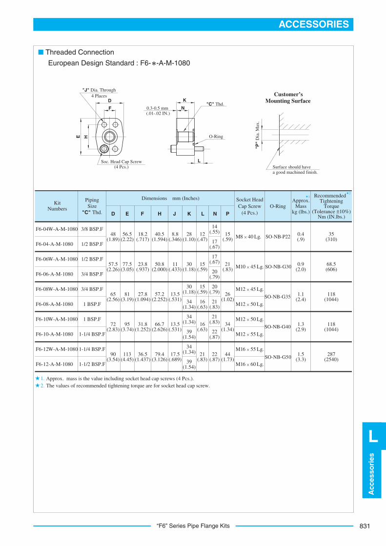
European Design Standard : F6- -A-M-1080
Customer’sMounting Surface
■ Threaded Connection
1.2.
21
Approx.Mass
kg (lbs.)
Socket Head Cap Screw
(4 Pcs.)O-Ring
RecommendedTightening
Torque(Tolerance ±10%)
Nm (IN.lbs.)
PipingSize
"C" Thd.
KitNumbers
Dimensions mm (Inches)
D E F J L NH K
3/8 BSP.F
1/2 BSP.F
1/2 BSP.F
3/4 BSP.F
3/4 BSP.F
1 BSP.F
1 BSP.F
1-1/4 BSP.F
1-1/4 BSP.F
1-1/2 BSP.F
F6-04W-A-M-1080
F6-04-A-M-1080
SO-NB-P22
SO-NB-G30
SO-NB-G35
SO-NB-G40
SO-NB-G50
M8 40 Lg.
M10 45 Lg.
14(.55) 15
(.59)
P
M12 45 Lg.
M12 50 Lg.
M12 50 Lg.
M12 55 Lg.
M16 55 Lg.
M16 60 Lg.
F6-06W-A-M-1080
F6-06-A-M-1080
F6-08W-A-M-1080
F6-08-A-M-1080
F6-10W-A-M-1080
F6-10-A-M-1080
F6-12W-A-M-1080
F6-12-A-M-1080
0.4(.9)
35(310)
68.5(606)
118(1044)
118(1044)
287(2540)
0.9(2.0)
1.1(2.4)
1.3(2.9)
1.5(3.3)
21(.83)
26(1.02)
34(1.34)
44(1.73)
17(.67)
17(.67)
20(.79)
20(.79)
21(.83)
21(.83)
22(.87)
22(.87)
12(.47)
15(.59)
15(.59)
16(.63)
16(.63)
21(.83)39
(1.54)
34(1.34)
34(1.34)
39(1.54)
34(1.34)
30(1.18)
30(1.18)
28(1.10)
8.8(.346)
11(.433)
13.5(.531)
13.5(.531)
17.5(.689)
40.5(1.594)
50.8(2.000)
57.2(2.252)
66.7(2.626)
79.4(3.126)
18.2(.717)
23.8(.937)
27.8(1.094)
31.8(1.252)
36.5(1.437)
56.5(2.22)
48(1.89)
77.5(3.05)
57.5(2.26)
81(3.19)
65(2.56)
95(3.74)
72(2.83)
113(4.45)
90(3.54)
Approx. mass is the value including socket head cap screws (4 Pcs.). The values of recommended tightening torque are for socket head cap screw.

“F6” Series Pipe Flange Kits832
Surface should have a good machined finish.
"Q"
Dia
. Max
.
"J" Dia. Through 4 Places
D
E
L
F
H
K
O-Ring
Soc. Head Cap Screw (4 Pcs.)
P
"N" D
ia.
Japanese Standard "JIS" &
■ Socket Welding
European Design Standard : F6- -B-M-10
N. American Design Standard : F6- -B-U-1090
Customer’sMounting Surface
21
1.2.
Approx.Mass
kg (lbs.)
Socket Head Cap Screw
(4 Pcs.)O-Ring
RecommendedTightening
Torque(Tolerance ±10%)
Nm (IN.lbs.)
PipingSize
KitNumbers
Dimensions mm (Inches)
D E F J N QH L
3/8
1/2
1/2
3/4
3/4
1
1
1-1/4
1-1/4
1-1/2
F6-04W-B-M-10
F6-04W-B-U-1090
F6-04-B-M-10
F6-04-B-U-1090
48(1.89)
56.5(2.22)
K P
M8 40 Lg.
5/16-18UN C 1-1/2 Lg.
M8 40 Lg.
5/16-18UNC 1-1/2 Lg.
SO-NB-P22
SO-NB-G30
SO-NB-G35
SO-NB-G40
SO-NB-G50
M10 45 Lg.
3/8-16UNC 1-3/4 Lg.
M10 45 Lg.
3/8-16UNC 1-3/4 Lg.
M12 45 Lg.
7/16-14UNC 1-3/4 Lg.
M12 45 Lg.
7/16-14UNC 1-3/4 Lg.
M12 50 Lg.
1/2-13UNC 2 Lg.
M12 50 Lg.
1/2-13UNC 2 Lg.
M16 55 Lg.
5/8-11UNC 2-1/4 Lg.
M16 55 Lg.
5/8-11UNC 2-1/4 Lg.
F6-06W-B-M-10
F6-06W-B-U-1090
F6-06-B-M-10
F6-06-B-U-1090
F6-08W-B-M-10
F6-08W-B-U-1090
F6-08-B-M-10
F6-08-B-U-1090
F6-10W-B-M-10
F6-10W-B-U-1090
F6-10-B-M-10
F6-10-B-U-1090
F6-12W-B-M-10
F6-12W-B-U-1090
F6-12-B-M-10
F6-12-B-U-1090
57.5(2.26)
65(2.56)
72(2.83)
90(3.54)
18.2(.717)
40.5(1.594)
8.8(.346)
77.5(3.05)
23.8(.937)
50.8(2.000)
11(.433)
81(3.19)
27.8(1.094)
57.2(2.252)
13.5(.531)
95(3.74)
31.8(1.252)
66.7(2.626)
13.5(.531)
113(4.45)
36.5(1.437)
79.4(3.126)
17.5(.689)
28(1.10)
26(1.02)
28(1.10)
26(1.02)
30(1.18)
30(1.18)
26.5(1.04)
26.5(1.04)
12(.47)
12(.47)
12.1(.48)
12.1(.48)
15(.59)
14.5(.57)
15(.59)
14.5(.57)
15(.59)
15(.59)
18(.71)
18(.71)
16(.63)
16(.63)
16.8(.66)
16.8(.66)
21(.83)
23.2(.91)
21(.83)
23.2(.91)
30(1.18)
22.2(.874)
22.2(.874)
27.7(1.091)
27.7(1.091)
34.5(1.358)
34.5(1.358)
43.2(1.701)
43.2(1.701)
49.1(1.933)
17.8(.701)
9(.35)
11(.43)
11(.43)
12(.47)
12(.47)
14(.55)
14(.55)
16(.63)
16(.63)
18(.71)
44(1.73)
34(1.34)
26(1.02)
21(.83)
15(.59)
34(1.34)
34(1.34)
0.4(.9)
0.9(2.0)
1.1(2.4)
1.3(2.9)
1.5(3.3)
35(310)
68.5(606)
118(1044)
118(1044)
287(2540)
Approx. mass is the value including socket head cap screws (4 Pcs.).The values of recommended tightening torque are for socket head cap screws.