access and hand instrumentation - cloud object storage€¦ · the ideal access cavity requirements...
TRANSCRIPT

26/06/2014
1
Masters in General Dental Practice
A.S. McRobert
The Ideal Access Cavity Requirements
Pre-operative Assessment
Straight Line Access
My Approach – Hands On Session 1
Alternative Approach
Anatomical Variation
Pre-existing Restorations
Hand Files, Negotiation and Glide Path Creation
Hand Instrumentation – Hands On Session 2
“ The objective of an access preparation is to create a smooth, straight-line path to the canal system and, ultimately the apex”
Pathways of the Pulp
Cohen & Burns
Must have Convenience form BUT must be done without weakening tooth structure needlessly.
Must walk a fine line.
Always an opportunity for disaster!
Prognosis can plummet within seconds!
Perforations occurring during access are typically difficult to repair.
Inability to locate canals leads to short term failure of treatment – embarrassing!
Enter the pulp chamber with care and suspicion
Good quality PA’s with Holder
Perpendicular and mesially angled views
Assess opening
Check ACJ with Perio probe
Palpate attached gingivae to discover root location and direction
Discuss procedure with patient – eg. Dam

26/06/2014
2
Canal disappears as it extends apically
Appearance of two periodontal ligaments along one side of root
“Straight-line access allowed the greatest proportion of the root canal wall to be instrumented…”
Mannan et al. IEJ 2001;34:176-83
“…opening the coronal end and straightening the curvature….generates a lesser restoring force (for instruments).. Roane et al. JOE 1985;11:203-11

26/06/2014
3
Armamentarium
Principles
Execution
26/06/2014
4
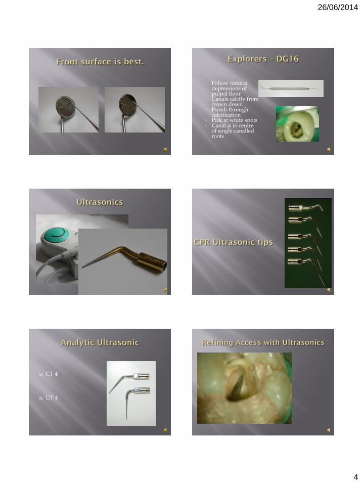
Follow natural depressions of pulpal floor
Canals calcify from crown down
Punch through calcification
Pick at white spots Canal is in centre
of single canalled roots
CT 4
UT 4

26/06/2014
5

26/06/2014
6
0.5 0.7 0.9 1.1 1.3 1.5
Width (mm)
Allows you to see where the bur is cutting.
Turbine head does not obscure view as much.
Ideal for refining access cavity to match anatomy.
Allows you to see where the bur is cutting.
Turbine head does not obscure view as much.
Ideal for refining access cavity to match anatomy.
Allows you to see where the bur is cutting.
Turbine head does not obscure view as much.
Ideal for refining access cavity to match anatomy.

26/06/2014
7

26/06/2014
8

26/06/2014
9
Helps eliminate ‘Taper Lock’
Ensures you don’t ‘lose the canal’
Gives room for GG’s to work

26/06/2014
10

26/06/2014
11

26/06/2014
12
Use on up-stroke
Apply slight lateral pressure
Size 4 then 3 then 2. (2,3,4 if sclerosed)
Slower speeds
Use to blend coronal third of canal into wall of access cavity – create a GLIDE PATH.
Anticurvature instrumentation
Inappropriate use of Gates Gliddens
Coke bottle prep
Only use nos.(1), 2, 3
in the root canal
Done using hand held stainless steel K-Files
Watch wind-pull action
Sizes (10) 15, 20 (25)
Followed by Gates Glidden drills as required
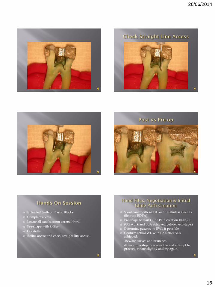
Confirm Straight Line Access and Working Length before canal preparation

26/06/2014
13

26/06/2014
14

26/06/2014
15
26/06/2014
16
Extracted teeth or Plastic Blocks
Complete access
Locate all canals, scout coronal third
Pre-shape with k-files
GG drills
Refine access and check straight line access
Scout canal with size 08 or 10 stalinless steel K-file. (use EDTA)
Pre-shape to start Glide Path creation 10,15,20.
(GG work and SLA achieved before next stage.)
Determine patency to EWL if possible.
Confirm actual WL with EAL after SLA achieved.
-Beware curves and branches.
-If you hit a stop, precurve file and attempt to proceed, rotate slightly and try again.

26/06/2014
17
Armamentarium
Principles
Execution

26/06/2014
18

26/06/2014
19

26/06/2014
20
Equivalent to GG 1 to 4
Use at 500 to 800 rpm.
Text book access cavity designs should be used as a guide only.
Access cavity should be shaped according to the individual internal anatomy of the tooth.
Must be aware of variations in anatomy for individual teeth.
“..classic access drawings are far too mesial.”
Wilcox et al JOE 1989;15:315-318
Ovoid or rounded triangle access palatally.
Needs to approach incisal edge for straight line access.
Danger of perforation labially.

26/06/2014
21
Narrow Mesio-Distally at ACJ level
May have Ovoid or Hourglass X-section
Easy to perforate
2 canals in 41% or more
Projection of central axis of canal exits at incisal edge or even labially
4’s usually 2 rooted, 5’s usually 1.
May be 3 roots in either.
Width of root at ACJ only 2/3 width of crown.
Mesial concavity on 4’s, easily perf’d.

26/06/2014
22
P. Lumley
P. Lumley P. Lumley
26/06/2014
23
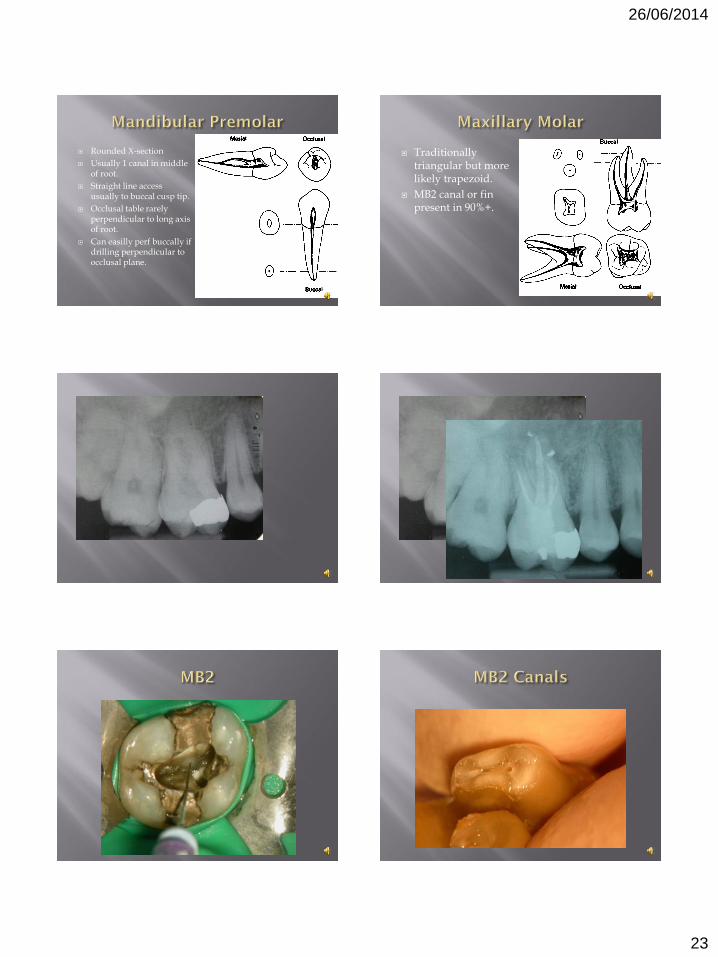
Rounded X-section
Usually 1 canal in middle of root.
Straight line access usually to buccal cusp tip.
Occlusal table rarely perpendicular to long axis of root.
Can easilly perf buccally if drilling perpendicular to occlusal plane.
Traditionally triangular but more likely trapezoid.
MB2 canal or fin present in 90%+.
26/06/2014
24
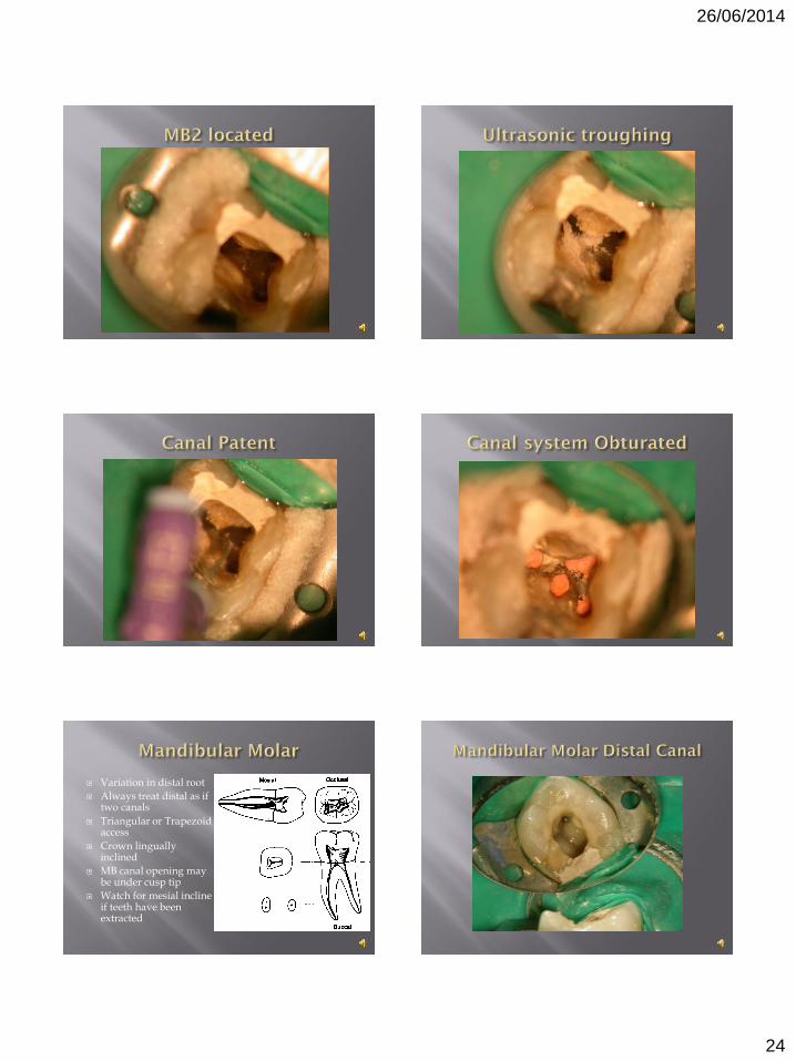
Variation in distal root
Always treat distal as if two canals
Triangular or Trapezoid access
Crown lingually inclined
MB canal opening may be under cusp tip
Watch for mesial incline if teeth have been extracted

26/06/2014
25
Radiographic assessment
To replace or not to replace
Full coverage restorations
Pick the correct tools for the job

26/06/2014
26
S.S. K-Files.
Insert into canal to light resistance.
Apply only light apical pressure.
Watch-wind in fingers 2-3 times.
Sharp pull.
Used for Pre-shaping with size 10,15,20 in coronal and middle thirds of canal as soon as canals are located before GG’s.
After SLA with GG’s
Size 10 K-file (8 if necessary)
EDTA gel
Watch wind down to estimated WL
Confirm with EAL
Watch for taper lock
Curvatures and impediments are the challenge

26/06/2014
27
Lubricants Initial irrigant Keep debris in suspension Emulsify pulp stump
in vital cases Faster cutting Cleaner canal Less file separation

26/06/2014
28
Performed after straight line access is achieved and working length established.
Using watch-wind and pull motion.
Try to get 10, 15 and 20 K-files to WL.
Can then use any canal preparation method with ease and safety.
File Manipulation (K-Files)
Watch-wind
Push-Pull
Balanced forces
Reversed balanced force
Canal Preparation technique
Step back
Crown down
As file passes into canal, gently rotate slightly back and forth until resistance met.
Apply slight apical pressure.
Rotate file slightly in one direction and then immediately in the other direction.
Repeat this twice more.
Pull file swiftly out of the canal in anti-curvature direction.
Use with care!!
Small in-out motion, only 1-2mm
Used to open very narrow areas of the canal which were difficult to locate
Move to Watch-Wind as soon as possible
Can ledge canal if not used appropriately
Placement;
Apply inward pressure and rotate clockwise 60°
Cutting;
Apply inward pressure (to match file size) and rotate counterclockwise 120°
Removal;
Withdraw gradually while rotating clockwise

26/06/2014
29
GT Files – Reverse Balanced Forces
Insertion
Watchwinding until snug Engage 45-90o anti clockwise
Cutting (Apical pressure & clockwise)
Flute loading (Coronal pull & anti clockwise)
Check where debris is when pull intsrument out
Preparation Techniques
Crown Down
Double Flare
Step back
File Manipulation Techniques
Watch Wind
Push-pull
Balanced Forces
Reverse Balanced Forces
After WL is established complete final Glide Path creation
Size 20 k-file to WL
Complete step back preparation with k-files using Watch-Wind
Hand GT or Protaper can be used instead
Objective of glide path creation with straight line access allowing a size 20 K-file to glide smoothly from the occlusal surface down to the working length.
This allows the operator to safely use any of the recognised canal preparation systems to shape the root canal.
Failure to achieve glide path creation in this way will increase the incidence of problems and failure.