accepted for publication in journal of cleaner production ... · and john summerscales p 4, p * ......
TRANSCRIPT

Accepted for publication in Journal of Cleaner Production (DOI: 10.1016/j.jclepro.2014.01.091) 30-Jan-2014.
1
In-mould gel-coating of polymer composites – a review
William RogersP
1P, Christopher HoppinsP
2P, Zoltán GombosP
3 Pand John SummerscalesP
4,P*
* Corresponding author. Tel.: +44 1752586150. E-mail address: [email protected] University of Plymouth, Plymouth, Devon, United Kingdom, PL4 8AA.
P
1P Strategic Development Manager, Submarine Business Unit, Babcock International Group, Plymouth PL1 4SG
P
2P Chief Engineer, "Ambassador" (Jersey Registered Sunseeker Yacht), Jersey Harbours,
Maritime House, La Route Du Port Elizabeth, St Helier, Jersey JE1 1HB, P
3P Research Fellow, Advanced Composites Manufacturing Centre, School of Marine Science and Engineering,
Faculty of Science & Environment, University of Plymouth. P
4P Associate Professor (Reader) in Composites Engineering, Advanced Composites Manufacturing Centre, School of Marine Science and Engineering, Faculty of Science & Environment, University of Plymouth.
Abstract: Fibre-reinforced polymer matrix composites find use in most transport applications, chemical plant, renewable energy systems, pipelines and a variety of other industries. These applications often require a surface finish for cosmetic and/or durability reasons. The coating is usually polyester or vinyl-ester gel-coat painted or sprayed onto the mould tool before the structural composite is laminated. Alternatively a (typically polyurea) coating may be sprayed onto the surface of the cured composite part. The process may emit vapours (normally volatile organic compounds, VOC) into the workplace and the environment. This review paper will consider the potential for in-mould gel-coating as a route to improved workplace conditions and reduced environmental impact. It will also address measurement of quality by adhesion, surface characterisation, and long-term durability. Customer satisfaction is the key driver for gel-coated products. Keywords: closed mould processing, surface coatings, gel-coat, adhesion, wave-scan, surface characterisation. 1. Introduction Recent statistics for the fibre reinforced polymer matrix composites industry show production of 2.7 million tonnes of material in the United States of America (Anon., 2012) and over 2.2 million tonnes in the European Union (Anon., 2013a). These components are supplied to a wide variety of industries and many require a surface coating for cosmetic or durability reasons (Pritchard, 1999)2T.2T Such a coating can be applied as a paint/gel-coat (Weiss, 1997; Grainger and Blunt, 1998; Lambourne and Strivens, 1999; Ryntz and Yaneff, 2003; Tracton, 2006) or by electrostatic deposition of a powder (Liberto, 2003; Norris, 2003; Roobol, 2003; Utech, 2002; Hughes, 2002) or can be sprayed onto the cured composite part (Anon., 2013b,c; LeBlanc et al, 2013). Lubin (1982) states that a gel-coat should be highly decorative, protective, glossy and require no post finishing. Some current commercially available gel-coat systems are listed in Appendix 1. High-performance composites (e.g. aerospace components) are manufactured by vacuum bagging of prepreg with autoclave cure (Witik et al, 2012). More cost-effective components may be manufactured in a closed mould using compression moulding (Bhattacharyya, 1997; Lim and Ramakrishna, 2002; Long, 2007), resin infusion (Williams et al., 1996; Cripps et al., 2000; Summerscales and Searle, 2005; Beckwith, 2007; Summerscales, 2012) or resin transfer moulding (Kruckenberg and Paton, 1998; Rudd, 1997; Tucker and Dessenberger, 1994; Van Harten, 1993; Benjamin and Beckwith, 1999; Parnas, 2000; Potter, 1997). Each of these processes has the potential for the coating to be applied in the mould during the process to limit release of solvents to the atmosphere and improve the accuracy of the film
Accepted for publication in Journal of Cleaner Production (DOI: 10.1016/j.jclepro.2014.01.091) 30-Jan-2014.
2
thickness. This could also improve the surface finish and extend the durability of the component. The most common reactive diluent in polymer matrix composites is styrene, especially in the manufacture of fibreglass reinforced plastics (Miller et al., 1994). Styrene has been the subject of extensive debate in respect of health and environmental issues. Although people have worked in the industry for their full normal working life there is no significant evidence of long-term effects from exposure at normal working levels. Forthcoming styrene risk assessments by the European Union, monitored by European Chemical Industry Council (CEFIC) for the chemicals industry, are expected to be the major driver in the near future regarding styrene classification, labelling and use. Reduced styrene levels in the workplace are expected to improve retention of workforce personnel, minimise release to the environment and reduce odour at the factory boundary. The European Styrene Producers Association has recently (Faes, circa 2011) recommended that Occupational Exposure Standards should be reduced. The recommendation for 20 ppm time-weighted average (TWA) is unlikely to be achievable with open mould gel-coating. The adoption of in-mould coating may require:
• Control of mould opening distance to define the cavity into which the coating will flow, leading to predetermined coating thickness.
• Changes to the formulation of the coating system to achieve an appropriate viscosity for flow coating.
• Changes in the solvent content to compensate for the reduced evaporation or changed chemical constituents.
• Lower shrinkage of the gel-coat to reduce pre-release surface defects on the moulded cosmetic surface arising during the curing process.
• Optimisation of resin flow to achieve complete fill in such moulds. • Novel techniques to minimise surface defects after the flow coating process. • Achievement of a good bond between the laminate and the coating. • Separation of the two resin systems, to avoid mixing and discolouration. •
Askham et al (2012) considered specific legislative and/or environmental requirements and have developed a framework for the simultaneous analysis of multiple product development drivers to balance economic, environmental and health and safety (REACH) for a variety of products. 2. Methods The methodological approach for the literature review is briefly described. This review article is focused on the in-mould coating (IMC) techniques and their main characterisation methods especially in case of gel-coatings. Papers from numerous scientific journals, conference proceedings, commercial websites and most relevant patents related to the topic were selected and reviewed. Different IMC processes such as compression moulding, injection moulding, Liquid Composite Moulding (LCM) and Resin Infusion under Double Flexible Tooling (RIDFT) were discussed independently. The article describes the possible flow modelling and optimisation for IMC, then characterisation methods such as adhesion tests, surface finish measurement techniques. The Appendix presents a small selection from the vast range of commercial IMC and hand application products available.

Accepted for publication in Journal of Cleaner Production (DOI: 10.1016/j.jclepro.2014.01.091) 30-Jan-2014.
3
3. In-Mould Coating (IMC) processes The majority of IMC systems rely on controlled mould opening. This heavily limits the geometry of moulded parts to those having low moulding angles or increases the complexity of the tooling where surfaces parallel to the mould opening axis are to be coated. Multi-part moulds would have to be produced in these cases, at considerable expense. 3.1 Compression moulding Sheet moulding compound (SMC) components are widely used for high-volume moulding of large, rigid parts such as automotive bodywork or low performance structural parts, such as electrical machinery housings and sanitary ware (Anon., 2001, 2013d). IMC processes, leaving a primer-like finish to the components, have been developed to replace existing paint finishes which have their own limitations. They may suffer extensively from poor surface finish due to surface porosity, waviness and sinks. IMC has been successfully developed for use with compression moulded SMC (Toro et al., 2005). Low pressure IMC (LPIMC) involves opening the mould to approximately 1 mm after moulding the component, and injecting the IMC into the cavity and re-closing the mould. The applied force spreads the IMC within the mould (Straus, 2005). In high pressure IMC (HPIMC), clamping force is maintained (~20-35 MPa) and the compressibility of the SMC substrate and the injection pressure are relied on to displace the upper tool (Straus, 2005). Original features in each process are documented in the respective patents (Arnason, 1980, 1983), including two-stage cure processes based on slight mould opening and/or using specially formulated coatings (epoxide and unsaturated carboxylic acid mixed with a low shrink additive) that will adhere to un-cleaned mouldings. Bigg and Markle (1996) highlight the viscosity/flow problems with slight mould opening and present a formulation for a unique material. This new material behaves as a thermoplastic at elevated temperatures and a thermoset at use temperatures. At manufacturing temperature, it has a viscosity suitable for flow in the slightly opened mould. Straus and McBain (2003) developed a process based on slight mould opening that allows thermoset gel-coat to be moulded to a thermoplastic component. In addition, LPIMC injection techniques (Nobuyuki et al., 1991) for slight mould opening have been developed for TMC (Thick Moulding Compound) and BMC (Bulk Moulding Compound) alongside SMC. Åström (1997) highlights the difference between high and low pressure IMC injection, identifying that LPIMC adds time to the moulding process and has reduced consolidation and is consequently undesirable. HPIMC has some ability to coat vertical mould parts by compressing the matrix (Straus, 2005). Compression moulded components with cosmetic or abrasion resistant skin requirements have been manufactured without the need for component removal from the mould before skin application (Ditto, 1978). This has the benefit of reduced surface contamination; resulting in a higher level of adhesion and can produce a Class A finish for automotive applications. These high quality finishes have been further improved by the development of high temperature and high crack durability (toughened) isocyanates for thermoplastic IMC (Markle et al., 1978, Bigg et al.,1993). 3.2 Injection moulding IMC is also achieved via reduced clamping in injection moulded thermoplastics (Yamamoto and Yonemochi, 2001) allowed by specially formulated compositions (Yamamoto et al., 1998). In Mould Decorating (IMD) is closely linked to IMC processes, as decorative surfaces and patterns are added to a moulding while in the mould (Puentes and Okoli, 2006;
Accepted for publication in Journal of Cleaner Production (DOI: 10.1016/j.jclepro.2014.01.091) 30-Jan-2014.
4
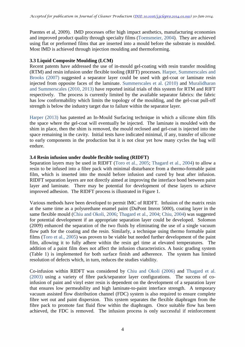
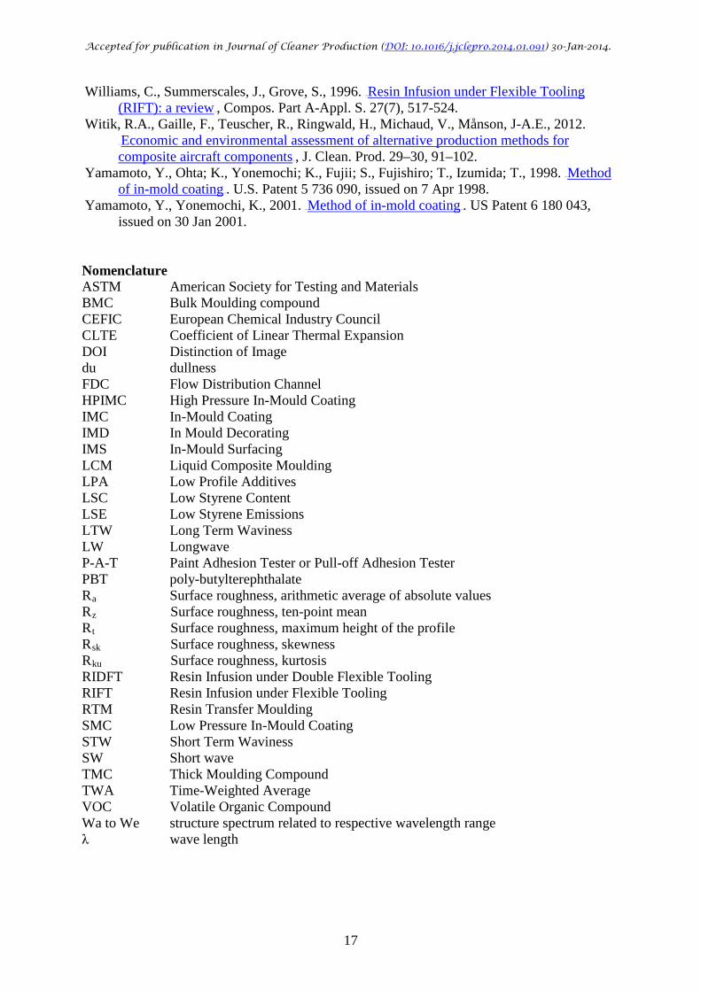
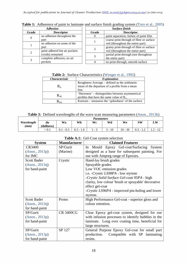
Puentes et al, 2009). IMD processes offer high impact aesthetics, manufacturing economies and improved product quality through specialty films (Toensmeier, 2004). They are achieved using flat or preformed films that are inserted into a mould before the substrate is moulded. Most IMD is achieved through injection moulding and thermoforming. 3.3 Liquid Composite Moulding (LCM) Recent patents have addressed the use of in-mould gel-coating with resin transfer moulding (RTM) and resin infusion under flexible tooling (RIFT) processes. Harper, Summerscales and Brooks (2007) suggested a separator layer could be used with gel-coat or laminate resin injected from opposite faces of the laminate. Summerscales et al. (2010) and Muralidharan and Summerscales (2010, 2013) have reported initial trials of this system for RTM and RIFT respectively. The process is currently limited by the available separator fabrics: the fabric has low conformability which limits the topology of the moulding, and the gel-coat pull-off strength is below the industry target due to failure within the separator layer. Harper (2013) has patented an In-Mould Surfacing technique in which a silicone shim fills the space where the gel-coat will eventually be injected. The laminate is moulded with the shim in place, then the shim is removed, the mould reclosed and gel-coat is injected into the space remaining in the cavity. Initial tests have indicated minimal, if any, transfer of silicone to early components in the production but it is not clear yet how many cycles the bag will endure. 3.4 Resin infusion under double flexible tooling (RIDFT) Separation layers may be used in RIDFT (Toro et al., 2005; Thagard et al., 2004) to allow a resin to be infused into a fibre pack with minimal disturbance from a thermo-formable paint film, which is inserted into the mould before infusion and cured by heat after infusion. RIDFT separation layers are not directly aimed at improving the interface bond between paint layer and laminate. There may be potential for development of these layers to achieve improved adhesion. The RIDFT process is illustrated in Figure 1. Various methods have been developed to permit IMC of RIDFT. Infusion of the matrix resin at the same time as a polyurethane enamel paint (DuPont Imron 5000), coating layer in the same flexible mould (Chiu and Okoli, 2006; Thagard et al., 2004; Chiu, 2004) was suggested for potential development if an appropriate separation layer could be developed. Solomon (2009) enhanced the separation of the two fluids by eliminating the use of a single vacuum flow path for the coating and the resin. Similarly, a technique using thermo formable paint films (Toro et al., 2005) was proven to be viable but needed further development of the paint film, allowing it to fully adhere within the resin gel time at elevated temperatures. The addition of a paint film does not affect the infusion characteristics. A basic grading system (Table 1) is implemented for both surface finish and adherence. The system has limited resolution of defects which, in turn, reduces the studies viability. Co-infusion within RIDFT was considered by Chiu and Okoli (2006) and Thagard et al. (2003) using a variety of fibre pack/separator layer configurations. The success of co-infusion of paint and vinyl ester resin is dependent on the development of a separation layer that ensures low permeability and high laminate-to-paint interface strength. A temporary vacuum assisted flow distribution channel (FDC) system is also required to ensure complete fibre wet out and paint dispersion. This system separates the flexible diaphragm from the fibre pack to promote fast fluid flow within the diaphragm. Once suitable flow has been achieved, the FDC is removed. The infusion process is only successful if reinforcement
Accepted for publication in Journal of Cleaner Production (DOI: 10.1016/j.jclepro.2014.01.091) 30-Jan-2014.
5
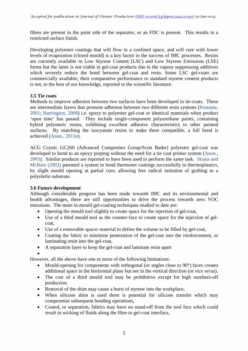
fibres are present in the paint side of the separator, or an FDC is present. This results in a restricted surface finish. Developing polyester coatings that will flow in a confined space, and will cure with lower levels of evaporation (closed mould) is a key factor in the success of IMC processes. Resins are currently available in Low Styrene Content (LSC) and Low Styrene Emissions (LSE) forms but the latter is not viable in gel-coat products due to the vapour suppressing additives which severely reduce the bond between gel-coat and resin. Some LSC gel-coats are commercially available; their comparative performance to standard styrene content products is not, to the best of our knowledge, reported in the scientific literature. 3.5 Tie coats Methods to improve adhesion between two surfaces have been developed in tie-coats. These are intermediate layers that promote adhesion between two different resin systems (Poutasse, 2001; Harrington, 2008) i.e. epoxy to polyester gel-coat or identical materials when product ‘open time’ has passed. They include single-component polyurethane paints, containing hybrid polymeric resins, exhibiting excellent adhesive characteristics to other painted surfaces. By matching the isocyanate resins to make them compatible, a full bond is achieved (Anon., 2013e). ACG Crystic GC260 (Advanced Composites Group/Scott Bader) polyester gel-coat was developed to bond to an epoxy prepreg without the need for a tie coat primer system (Anon., 2003). Similar products are reported to have been used to perform the same task. Straus and McBain (2003) patented a system to bond thermoset coatings successfully to thermoplastics, by slight mould opening at partial cure, allowing free radical initiation of grafting to a polyolefin substrate. 3.6 Future development Although considerable progress has been made towards IMC and its environmental and health advantages, there are still opportunities to drive the process towards zero VOC emissions. The main in-mould gel-coating techniques studied to date are:
• Opening the mould tool slightly to create space for the injection of gel-coat, • Use of a third mould tool as the counter-face to create space for the injection of gel-
coat, • Use of a removable spacer material to define the volume to be filled by gel-coat, • Coating the fabric to minimise penetration of the gel-coat into the reinforcement, or
laminating resin into the gel-coat, • A separation layer to keep the gel-coat and laminate resin apart •
However, all the above have one or more of the following limitations: • Mould-opening for components with orthogonal (or angles close to 90°) faces creates
additional space in the horizontal plane but not in the vertical direction (or vice versa). • The cost of a third mould tool may be prohibitive except for high numbers-off
production. • Removal of the shim may cause a burst of styrene into the workplace, • When silicone shim is used there is potential for silicone transfer which may
compromise subsequent bonding operations, • Coated, or separation, fabrics may have no stand-off from the tool face which could
result in wicking of fluids along the fibre to gel-coat interface,

Accepted for publication in Journal of Cleaner Production (DOI: 10.1016/j.jclepro.2014.01.091) 30-Jan-2014.
6
• Separation layers are not yet available with the ability to conform to complex geometry components.
• The gel-coat to laminate interface may be the weak point in the system with low gel-coat pull-off strengths.
Of course, in addition to solving all the above issues, the gel-coated surface should normally be distortion-free with a high-gloss finish. In consequence, there are a number of research themes which could be explored to enhance the respective technologies and create commercially exploitable gel-coating systems. 4. Flow modelling and optimisation Computer programs which predict the flow during IMC are available (Lee et al., 1984; Osswald and Tucker, 1990) and have been used to successfully model part production (Castro and Griffith, 1990). Modelling of IMC is discussed by Cabrera-Rios et al (2002). Two factors are identified that are critical for the success of SMC IMC process. These include optimisation of the injection gate location for minimisation or elimination of trapped air in the coating; and minimisation of cure time by optimisation of the IMC processing conditions. Linear regression and artificial neutral networks meta-modelling have proven successful in modelling optimal filling of moulds and predicting cure time. Neither the adhesion of the SMC/IMC coupled system nor the optimal cure cycle were considered in the model. This has the potential to heavily affect the models viability as the properties of the finished part are highly dependent on processing variables. Flow modelling of IMC is vital to ensure optimum cavity filling. However, many models only consider flow through one medium. An appreciation of different flow characteristics of inter-tow and intra-tow flow is vital for accurate flow modelling in clustered fibre reinforcements. This has been approached by Wang et al (2008), modelling 1-D RTM moulding, using separate simulations, coupled under the same numerical model. Similarly, flow modelling in the reinforcement (low permeability) and in the opened mould (very high permeability) requires very different numerical models. These must be carefully considered to accurately model an IMC process. 5. Adhesion testing methods A discussion of the adhesion of paints to surfaces has been published by Paint Research Association (Anon., 2006). Standards which are potentially suitable for adhesion testing of paints and flexible coatings include the following: BS EN ISO 2409 / BS 3900-E6 A lattice pattern is cut through the surface coating, reducing it to 25 squares with average distance of 1, 2 or 3 mm dependent on the thickness ranges of the coating, which are <60 µm, 60-120 µm, >120 µm, respectively. A piece of tape with defined adhesion strength is then applied and pulled off the lattice pattern. A pictorial scale categorises the pull off. The technique is fast, inexpensive, simple and can be used on site. However, it should be limited to a maximum coating thickness of 250 μm, and consequently is not suitable for the majority of gel-coat coatings which are typically >500 μm thick. The American Society for Testing and Materials (ASTM) equivalent standard is: D-3359-02 ‘Standard Test Methods for Measuring Adhesion by Tape Test’. BS EN 24624 / ISO 4624 This tensile pull-off test method, which has several variations and can quantify adhesion for rigid or flexible substrates with a paint finish on one (suitable just for rigid substrates) or both
Accepted for publication in Journal of Cleaner Production (DOI: 10.1016/j.jclepro.2014.01.091) 30-Jan-2014.
7
sides (general method for testing both rigid and deformable substrates). Test ‘dollies’ with 20 mm diameter cylinders can be attached to one or each side of the test material with suitable adhesive, and trimmed to the circumference of the cylinder. After cure of adhesive, the interface is pulled apart by a gradually increasing force (Figure 2). The results may be affected when there is an interaction between the adhesive and the coating and when cutting of the substrate affects the interface. Accurate adhesion strength can be calculated because the exact cross-section of the specimen is known. Accurate alignment is essential to avoid early failure due to cleavage or peel stresses arising from off-axis stresses. BS EN 24624/ISO 4624 is perhaps best suited to gel-coat applications. Film thicknesses of gel-coat, would be unlikely to permit the use of BS EN ISO 2409 / BS 3900-E6 using standard equipment as described by (Anon., 2013g). The Paint Research Association (Anon., 2006) specifies values of 20-40 kg/cmP
2P (2-4 MPa, NB: the source uses kg and not kgf so
kg/cmP
2P values must be multiplied by 98 to get kPa) as acceptable paint adhesion. Any value
above 40 kg/cmP
2P was deemed to be ‘good’ with the BS EN 24624 standard having a limit at
~200 kg/cmP
2P (20 MPa) due to the low properties of available adhesives (Anon., 2006).
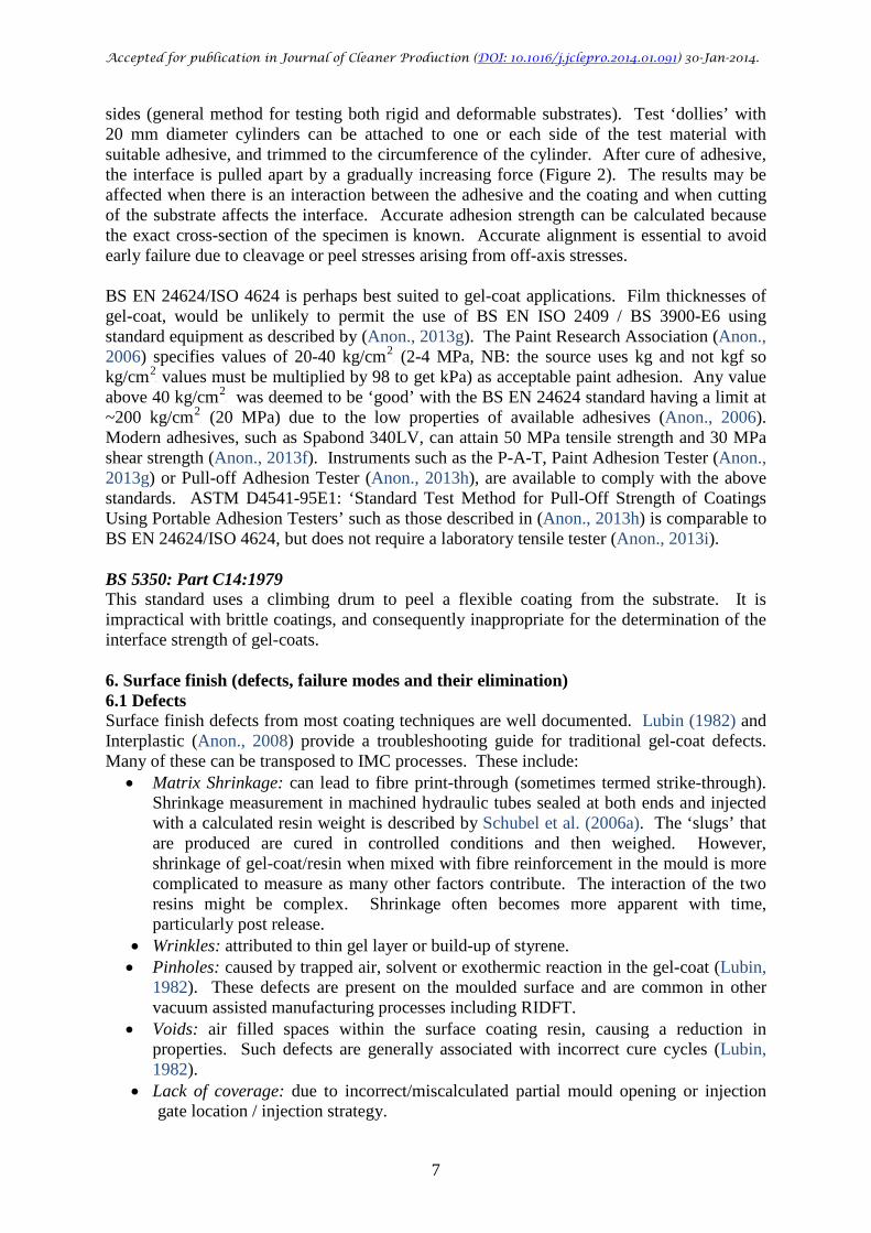
Modern adhesives, such as Spabond 340LV, can attain 50 MPa tensile strength and 30 MPa shear strength (Anon., 2013f). Instruments such as the P-A-T, Paint Adhesion Tester (Anon., 2013g) or Pull-off Adhesion Tester (Anon., 2013h), are available to comply with the above standards. ASTM D4541-95E1: ‘Standard Test Method for Pull-Off Strength of Coatings Using Portable Adhesion Testers’ such as those described in (Anon., 2013h) is comparable to BS EN 24624/ISO 4624, but does not require a laboratory tensile tester (Anon., 2013i). BS 5350: Part C14:1979 This standard uses a climbing drum to peel a flexible coating from the substrate. It is impractical with brittle coatings, and consequently inappropriate for the determination of the interface strength of gel-coats. 6. Surface finish (defects, failure modes and their elimination) 6.1 Defects Surface finish defects from most coating techniques are well documented. Lubin (1982) and Interplastic (Anon., 2008) provide a troubleshooting guide for traditional gel-coat defects. Many of these can be transposed to IMC processes. These include:
• Matrix Shrinkage: can lead to fibre print-through (sometimes termed strike-through). Shrinkage measurement in machined hydraulic tubes sealed at both ends and injected with a calculated resin weight is described by Schubel et al. (2006a). The ‘slugs’ that are produced are cured in controlled conditions and then weighed. However, shrinkage of gel-coat/resin when mixed with fibre reinforcement in the mould is more complicated to measure as many other factors contribute. The interaction of the two resins might be complex. Shrinkage often becomes more apparent with time, particularly post release.
• Wrinkles: attributed to thin gel layer or build-up of styrene. • Pinholes: caused by trapped air, solvent or exothermic reaction in the gel-coat (Lubin,
1982). These defects are present on the moulded surface and are common in other vacuum assisted manufacturing processes including RIDFT.
• Voids: air filled spaces within the surface coating resin, causing a reduction in properties. Such defects are generally associated with incorrect cure cycles (Lubin, 1982).
• Lack of coverage: due to incorrect/miscalculated partial mould opening or injection gate location / injection strategy.
Accepted for publication in Journal of Cleaner Production (DOI: 10.1016/j.jclepro.2014.01.091) 30-Jan-2014.
8
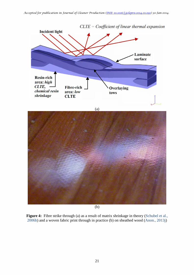
Painted SMC components are often susceptible to ‘paint popping’ due to air filled voids in the material expanding and bursting during heating for cure (Abrams and Castro, 2001) leading to a poor surface finish after the painted layers are heat cured. IMC offers the potential to reduce this defect if high pressure infusions are implemented allowing no voids. However IMC does not allow edge porosity to be sealed. As a result IMC has competition from powder coating technology: an out of mould process, with a poorer surface finish, but with the benefit of shorter mould usage times. 6.2 Controlling quality Self-levelling gives a huge advantage to painted components. Schubel et al. (2006b) suggest that mould surface does not contribute much towards a painted components surface finish, and finish is dominated by the fibre architecture. The vast numbers of processing and material variables in the application of IMC surface finishes create obvious difficulties in the control of quality. Consequently IMC processes must be assessed for their response to these variables. Kim et al. (1997) suggest that each manufacturing step imparts its own characteristic features in response to laminate or coating variables (Figure 3). Material features might also be included in this assessment, such as resin type, fibre type and the use of blockers or fillers. 6.3 Print-through (a.k.a. strike through) Print-through of the reinforcement topology (Figure 4) is attributed to volumetric shrinkage of the matrix during cure and is well illustrated by Schubel et al. (2006b). Matrix rich volumes deform unconstrained by reinforcement and leave surface pits. Print-through is a result of complex interactions between the gel-coat, the reinforcement and the resin during the manufacture of the composite component. Print-through should not affect the mechanical performance of the part, but can compromise the aesthetic appearance (Anon., 2007). Schubel et al. (2006b) note that the surface features are also related to tow size of the reinforcement fibre, although this effect is secondary to the matrix shrinkage. Shrinkage problems can be reduced by low-shrink resin additives, such as LPA (Low Profile Additives) including polyvinyl acetate (Schubel, 2006c) but have been shown to adversely increase VOC content (Pritchard, 1999; Reijnders, 2013). However, hydrophilic additives have been linked to the development of osmosis in the marine sector leading to blistering (Pritchard, 1999; Searle and Summerscales, 1999) and consequently are not appropriate in many applications. The use of nano-silicates has been shown to have the potential to reduce shrinkage, but as yet, has not been developed commercially (Lee et al., 1984). An alternative route to solving this shrinkage would be expanding monomers, such as Epolin epoxy developed over 20 years ago (although no longer commercially available). Mallick (1997) comments on the advantages of hand application of gel-coat, whereby print through of fibres is reduced by selecting reduced cure times or use of surface veils (Anon., 2013l,m,n) and/or barrier coats (Bell and Johnstone, 2008). Lightweight Structures (Anon., 2013o) suggest that the application method in infusion should be adjusted to reduce shrinkage, by means of adjusting pressure, injection time and controlled heating rather than increasing cost and weight using additional materials like surface veils and vinyl ester resins. Kaizen Technologies and Sogel Inc. (Anon., 2007) have developed a system called PrintShield™. A protective layer is applied to the gel-coat before the lamination of the reinforcement begins. The system is claimed to solve both print-through and surface profiling problems especially in closed molding processes (e.g. RTM and RIFT). The layer
Accepted for publication in Journal of Cleaner Production (DOI: 10.1016/j.jclepro.2014.01.091) 30-Jan-2014.
9
can be applied by brush or using a standard spraying gel-coater and can be applied up to two weeks before lamination. Over four years, more than 200 000 marine parts were produced using PrintShield™. 6.4 Surface finish (measurement of quality) The measurement of surface quality has been classified by Schubel et al. (2006b) into three broad categories (a) surface roughness, (b) short term waviness and (c) long term waviness. These features produce a typical surface profile when brought together.
• Surface roughness: Measured by scanning laser or stylus profiling and quantified as roughness parameters in the form RRaR, RRzR, RRtR. There is no previous evidence of using RRaR for laminate or paint surface characterisation. The latter often being characterised by topography or utilisation of wavelength parameters. In the study RRaR showed good correlation with reflectometry.
• Schubel et al. (2006b) used stylus profilometry to measure RRaR of unpainted laminates. It was deemed unsuitable for the characterisation of painted surfaces as there was no correlation to subjective assessments, and because fibre print-through was difficult to isolate from the linear trace. It was good at picking up print-through on unpainted laminates and relating bare laminates to those that were painted. It should be useful for comparing IMC components before and after coating. Wenger et al. (1992) suggest that surface finish characteristics (RRaR, RRskR, RRkuR) are a function of, and hence can be controlled by, cycle pressure and tooling quality (Table 2). RRaR improves with autoclave pressure. Skewness, RRskR has an optimum value at 400 kN/mP
3P due to expected
viscosity/temperature effects of the resin. Consequently, controlling process conditions will allow the manipulation of the surface finish. Abdelouahab et al. (1999) have developed a method of achieving different hardness values on opposing sides of laminates. This technique might have application in IMC where heat curing is required but excessive heat curing of the coating side may compromise its performance. An interesting application would be with the RIDFT thermoplastic layer (Toro et al., 2005), where curing cycles limit the processes success. Resins will preferentially cure towards the hotter side of a mould. This can be exploited to minimise shrinkage on the cosmetic side of the laminate.
• Short Term Waviness (STW): Associated with highly polished surfaces it is caused by scattering of reflected light. STW is associated with surface irregularities of sub-visible 0.3 < λ < 1.2 mm wavelength (i.e. fibre print-through or pinholes) and is generally only visible close (< 0.4 m) to the surface.
• Long Term Waviness (LTW): Associated with highly polished surfaces it is caused by scattering of reflected light. LTW is associated with 3 < λ < 30 mm and may be observed at approximately 3 m from the source (Schubel et al., 2006b). However, the Qualitest Wave-Scan II Model GB-4840 Operation Manual (Anon., 2013k) (see Table 3.) defines Longwave (LW) as 1.2 < λ < 12 mm.
• Short and longwave features are further sub-categorised (Schubel et al., 2006b) into five wavelengths labelled Wa to We spanning the visible spectrum. A non-visible region called dullness (du) is also used to assess quality. Qualitest manual (Anon., 2013k) further groups the features into Shortwave (SW) and Longwave (LW). Surface analysis techniques utilise a combination of the above spectra to create hybrid wavelength parameters used to characterise the surface structure. The parameters are summarised in Table 3.
Accepted for publication in Journal of Cleaner Production (DOI: 10.1016/j.jclepro.2014.01.091) 30-Jan-2014.
10
Wenger et al. (1992) characterised the surface in a similar manner, but without the distinction between short and long term waviness. Instead, errors of form (gross deviations from a flat surface) which we might assume to be an alternative description of LTW are defined as a surface characteristic. Wenger et al use RRaR to characterise surface finish of laminates against different processing conditions, contradicting Schubel et al. (2006b). An alternative surface measurement technique for high quality painted laminates is laser light modulation (BYK Gardner Wave-Scan DOI) (Schubel et al., 2006b), which may be useful when profilometry does not yield a full characterisation of surface. The nature of composite laminates requires both short and long wavelength techniques to be employed to characterise surface roughness. This was reported for paints applied after the moulding process and hence may not directly transpose to characterisation of IMC surfaces. For instance, in polyester systems, the interaction of two high shrinkage resins may cause variation, especially where the system does not have the advantage of ‘self-levelling’ experienced in painting. Wave-Scan DOI is standard equipment to quantify surface appearance used by automotive manufacturers (Schubel et al., 2006b). Osterhold and Armbruster (2006) suggest that the optical wave scan techniques show the same trend as profilometry derived RRaR values for poly-butylterephthalate (PBT)/glass fibre painted samples with varying fibre content. Wave-Scan DOI has been recently introduced to yacht manufacturing companies (Walker and McKelvie, 1987; Kim et al., 1997). This equipment determines the appearance by quantifying:
• Image Clarity: A finish often referred to as orange peel caused by the macroscopic surface roughness patterns of the product (wavy structures between 0.1-30 mm in structure size) (Anon., 2013o). The imperfection reflects light in varying directions. The human eye only accepts the light being reflected directly to our eyes. Image clarity is measured by detecting different light levels dependent on the local surface orientation.
• Distinction of Image (DOI): Measures the image brilliance when reflected, determining dullness/brightness of a reflection. It can comply with particular end-user requirements: for example the (now obsolete) Dorigon instrument was correlated to the ASTM E430 standard value range similar to 20° illumination angle gloss measurement, or it can be related to company specifications (GM, BYK).
• Other properties for different automotive partners can be identified (Anon., 2013k) such as lustre and sharpness (Ford), orange peel (Ford, Daimler Chrysler, Peugeot), tension scales for orange peel (General Motors, Mercedes Benz, Honda), ranking note for 1 or 3 m observation (BMW), etc.
• Walker and McKelvie (1987) highlight additional optical techniques for surface profiling. These include: triangulation, shadow moiré, projected fringes and holographic interferometry. Labrosse et al. (2011) captured digital images from light reflected from gel-coated surfaces onto a screen, then used image analysis to convert the grey-scale image to binary (black-or-white) and determine the fractal dimension to measure the surface quality. Each single number measurement was correlated to subjective assessments of surface quality for various gel-coated surfaces and to Wave-Scan DOI measurements.
Accepted for publication in Journal of Cleaner Production (DOI: 10.1016/j.jclepro.2014.01.091) 30-Jan-2014.
11
7. Conclusion/Summary This paper has reviewed the in-mould coating of fibre/polymer composites during closed mould manufacturing techniques. It considers processing techniques, coating formulation, flow processes in the manufacturing, coating/laminate adhesion, definition and measurement of surface quality. IMC is well developed for compression moulding and starting to show success in RIDFT. There is the opportunity for new approaches in RTM/RIFT processing, widening the adoption of IMC into the industry. However, the development of separator layers which combine formability to complex surface topologies without compromising gel-coat pull-off strengths remains a challenge. Systems which reserve the space for the gel-coat (silicone shim, or a third slightly larger counter-face (B-face) tool) for post-lamination application may offer a more practical solution for IMC. Imminent changes in occupational exposure standards are likely to drive new developments in gel-coating systems over the next few years. Acknowledgements The employment of WR and CPH was funded by the Department of Trade and Industry Technology Programme ‘Meeting the Challenge of the Zero Emission Enterprise’ call for funding our research under contract TP/4/ZEE/6/I/21058: Development of innovative in-mould coating technologies for gel-coating of composites. The employment of ZG was funded by the European Union's Seventh Framework Programme managed by REA-Research Executive Agency ([FP7/2007-2013] [FP7/2007-2011]) under grant agreement number FP7-SME-2011-1-286520. The authors are also grateful to Nigel Evans formerly at Pera Innovation (now at ARRK Europe Ltd) for assistance in identifying the appropriate literature. Appendix A: Some Commercial Gel-Coat Systems Table A1 below presents a small selection of the vast range of commercial products available for IMC and hand applied gel-coats. Research Highlights • The state-of-the-art in in-mould gel-coating (IMGC) is reviewed. • Changes in occupational exposure standards are likely to drive developments in IMGC. • Closed mould techniques will be essential for compliance with future regulations. • Separator layers for complex surfaces with good pull-off strengths is a challenge. • Gel-coat application post-lamination using reserved space may offer a practical IMC.
Accepted for publication in Journal of Cleaner Production (DOI: 10.1016/j.jclepro.2014.01.091) 30-Jan-2014.
12
References Abdelouahab, J., El Bourardi, A., Vergnaud, J.M., 1999. 10TUPreparation of Plane Composites
with different hardness on each faceU10T. Polym. Test. 18(3), 199-210. Abrams, L.M., Castro, J.M., 2001. 10TUPowder coating of Sheet Molding Compound (SMC)
body panelsU10T. Polym. Comp. 22(5), 702-709. Anon., 2001. Saint-Gobain Vetrotex, 2001. Sheet Moulding Compound: SMC,
10TUhttp://www.saint-gobain.com.cn/html/companypages/Vetrotex_hangzhou.htmU10T, accessed at 13:16 on 3 Dec 2013.
Anon., 2003. Netcomposites: New Epoxy Prepreg Compatible Gelcoat, 10TUhttp://www.netcomposites.com/news/new-epoxy-prepreg-compatible-gelcoat/1576U10T, accessed at 16:27 on 4 Nov 2013.
Anon., 2006. Paint Research Association: Coatings Technology Centre, Adhesion Testing, 10TUhttp://www.pra-world.com/technical_services/laboratory/testing/mechanical#iso4624U10T, accessed at 14:22 on 8 Oct 2013.
Anon., 2007. Kaizen Technologies and Sogel have solved the print through problem in Infusion and RTM. 10TUhttp://en.observatorioplastico.com/detalle_noticia.php?no_id=53188&seccion=construccion&id_categoria=5014U10T, accessed at 13:07 on 3 Oct 2013.
Anon., 2008. Trouble Shooting Guide/Gel Coat, Report P-086, Interplastic Corporation, St Paul MN, July 2008, 10TUhttp://www.interplastic.com/UserFiles/File/IP_GelCoatPoster08.pdfU10T, accessed at 11:33 on 16 Nov 2013.
Anon., 2012. The Composites Industry in North America, 10TUhttp://www.jeccomposites.com/events/jec-show-americas-2012/jec-show-americas-2012/american-composites-marketU10T, accessed at 16:13 on 9 Oct 2013.
Anon., 2013a. Eurasian composites 2013, 10TUhttp://www.netcomposites.com/calendar/eurasian-composites-2013/1266U10T, accessed at 16:18 on 9 Oct 2013.
Anon., 2013b. BASF Overhauls Wind Energy Coatings 10TUhttp://www.paintsquare.com/news/?fuseaction=view&id=7821U10T, accessed at 11:40 on 2 Oct 2013.
Anon., 2013c. VIP Germany, Polyurea coating technologies 10TUhttp://www.polyurea-solutions.com/en/applications/energy.htmlU10T, accessed at 11:48 on 3 Oct 2013.
Anon., 2013d. Bowitt Products Inc, Sheet Molding Compound, 10TUhttp://www.bowitt.com/materials/smc/smc.htmlU10T, accessed at 13:19 on 3 Dec 2013.
Anon., 2013e. RestoMotive Laboratories Division, 2002. Tie-Coat Primer, Product Information and Specification. POR-15 Inc., Morristown NJ, 10TUhttp://ananthacoatingsolutions.com/images/tie%20coat%20information%20sheet.pdfU10T, accessed at 13:37 on 3 Dec 2013.
Anon., 2013f. Gurit, Products & Materials, Adhesives. 10TUhttp://www.gurit.com/products-and-materials.aspxU10T, accessed at 9:55 on 3 Oct 2013.
Anon., 2013g. Paul N Gardner Company, Model P-A-T Paint Adhesion Test Kit, 10TUhttp://www.gardco.com/pages/adhesion/PATkit.cfmU10T, accessed at 12:41 on 3 Dec 2013.
Anon., 2013h. DFD Instruments: Precision Pull-off Adhesion Test Equipment, Selector Guide Paints and Protective Coatings 10TUhttp://www.dfdinstruments.co.uk/index.htmU10T, accessed at 10:48 on 4 Nov 2013.
Anon., 2013i. DeFelsko, PosiTest®: Pull-Off Adhesion Tester 10TUhttp://www.defelsko.com/adhesion-tester/adhesiontester.htmU10T, accessed at 11:10 on 4 Nov 2013.
Accepted for publication in Journal of Cleaner Production (DOI: 10.1016/j.jclepro.2014.01.091) 30-Jan-2014.
13
Anon., 2013j. One Ocean Kayaks. Epoxy Shrinkage. 10TUhttp://www.oneoceankayaks.com/Epoxyhtm/epox6m.htmU10T, accessed at 12:05 on 3 Dec 2013.
Anon., 2013k. Qualitest Wavescan II, Model GB-4840, Operation Manual, pp. 32-34. Anon., 2013l. Lantor Finishmat surfacing veils
10TUhttp://www.lantor.nl/index.php/id_structuur/10600/finishmat.htmlU10T, accessed at 13:12 on 14 Nov 2013.
Anon., 2013m. CHM Composites Ltd Advanced fibre non wovens 10TUhttp://chmcomposites.com/2012/07/synthetic-polyester-surfacing-veil-for-frp/U10T, accessed at 13:22 on 14 Nov 2013.
Anon., 2013n. Owens Corning OC surfacing veils 10TUhttp://www.owenscorningchina.com/Form_Up/Images/58513-A.pdfU 10T, accessed at 13:35 on 14 Nov 2013.
Anon., 2013o. Surface quality, Lightweight Structures B.V. 10TUhttp://www.lightweight-structures.com/surface-quality/index.htmlU10T, accessed at 13:04 on 03 Oct 2013.
Anon., 2013p. Gurit/SP Systems, Product Information, 10TUhttp://www.gurit.com/products-and-materials.aspxU10T, accessed at 12:09 on 3 Dec 2013.
Anon., 2013q. Scott Bader, Crystic Gel Coats, 10TUhttp://www.scottbader.com/composites/selector/?row=2U10T, accessed at 10:12 on 3 Oct 2013.
Anon., 2013r. Matrix Mouldings Ltd, Product Information. 10TUhttp://www.mcmc-uk.com/products.htmlU10T, accessed at 10:21 on 3 Oct 2013.
Anon., 2013s. Sicomin Epoxy Systems, Epoxy Systems-Gelcoat, 10TUhttp://www.sicomin.com/products-epoxy-48.aspxU10T, accessed at 10:28 on 3 Oct 2013.
Anon., 2013t. DSM Corporate, Liquid coating resins, 10TUhttp://www.dsm.com/markets/paint/en_US/liquid-lp.htmlU10T, accessed at 15:03 on 14 Oct 2013.
Anon., 2013u. Ferro, Products and Market, UltraShield® SuperShield® and HPC Gelcoat 10TUhttp://www.ferro.com/Our+Products/Specialty+Plastics/Liquid+Coatings+and+Dispersions/Products+and+Markets/Ultra+and+SuperShield+gelcoat/U10T, accessed at 12:18 on 3 Dec 2013.
Arnason, S.I., 1980. 10TUIn-mold coating of sheet molding compound moldingsU10T, US Patent 4 239 808, issued on 16 Dec 1980.
Arnason, S., 1983. 10TUIn-mold coating of sheet molding compound moldingsU10T, US Patent 4 367 192, issued on 04 Jan 1983.
Askham, C., Gade, A.L. and Hanssen, O.J., 2012. 10TUCombining REACH, environmental and economic performance indicators for strategic sustainable product developmentU10T, J. Clean. Prod. 35, 71–78.
Åström, B.T., 1997. 10TUManufacturing of Polymer CompositesU10T. Chapman & Hall, London. Beckwith, S.W., 2007. 10TUResin Infusion Technology: Part 1 - Industry highlightsU10T, 10TUPart 2 -
Process definitions and industry variationsU10T, 10TUPart 3 - A detailed overview of RTM and VIP infusion processingU10T, SAMPE Journal 43(1), 61 and 43(3), 46 and 43(4), 6 & 66-70.
Bell, S., Johnstone, E., 2008. 10TUISO-NPG gelcoats and barrier coatsU10T. JEC Composites Magazine 38, 38-41.
Benjamin, W.P, Beckwith, S.W. (eds.), 1999. Resin Transfer Moulding. SAMPE Monograph 3, Covina CA.
Bhattacharyya, D (ed.), 1997. 10TUComposite sheet formingU10T. Elsevier, Amsterdam. Bigg, D.M., Brusky, P.L., Cremeans, G.E., Elhard, J.D., Markle, R.A., Sowell, S., 1993.
10TUThermally-reversible isocyanate-based polymersU10T. US Patent WO 1993003080 A3, issued on 18 Mar 1993.
Accepted for publication in Journal of Cleaner Production (DOI: 10.1016/j.jclepro.2014.01.091) 30-Jan-2014.
14
Bigg, D., Markle, R., 1996. Isocyanate polymers for in mold coating of thermoplastic sheet composites. Plast. Eng. 52, 31-34.
Cabrera-Rios, M., Zuyev, K.S., Chen, X. and Castro, J.M.., 2002. 10TUOptimising Injection Gate Location and Cycle time For the In-Mould Coating (IMC) ProcessU10T. Polym. Composite 23(5), 723-738.
Castro, J.M., Griffith, R.M., 1990. 10TUMathematical Modeling of the In Mold Coating ProcessU10T. Polym. Eng. Sci. 30(11), 677-683.
Chiu, P., 2004. 10TUIn-Mold Coating of Composites Manufactured with the Resin Infusion between Double Flexible Tooling Process by Means of Co-InfusionU10T, MS dissertation, Florida State University.
Chiu, P., Okoli, O.I., 2006. 10TUIn-mold coating of composites manufactured by the resin infusion between double flexible tooling process by means of co-infusionU10T. J. Reinf. Plast. Comp. 25(5), 543-551.
Cripps, D., Searle, T.J., Summerscales, J., 2000. 10TUOpen Mould TechniquesU 10T, in: Talreja, R., Månson, J.-A. (eds.), Comprehensive Composite Materials Encyclopedia. Elsevier Science, Oxford, pp 737-761.
Ditto, E.D., 1978. 10TUMold coating of freshly molded articlesU10T, US Patent 4 076 788 A, issued on 28 Feb 1978.
Faes, E., undated circa 2011. Styrene Industry Recommends Occupational Exposure Limits. Styrene Producers Association letter.
Grainger, S., Blunt, J. (eds.), 1998. 10TUEngineering coatings: design and application, second edU10T. Woodhead Publishing, Cambridge.
Harper, A.R., Summerscales, J., Brooks, N., 2007. 10TUProduction of composite mouldingsU10T. GB Patent GB 2 432 336A, issued on 23 May 2007.
Harper, A.R., 2013. 10TUProduction of composite mouldingsU10T. GB Patent WO2013132211, issued on 2 Sep 2013.
Harrington, C., 2008. 10TUAdhesion promoting layer for composite assembliesU10T. World Patent WO 2008142474 A1, issued on 27 Nov 2008.
Hughes, J.F., 2002. 10TUElectrostatic Powder CoatingU 10T, in: Meyers, R.A. (ed.), 10TUEncyclopedia of Physical Science and Technology, third edU10T. Academic Press, Waltham MA. pp. 379-391.
Kim, K.-T., Jeong J.-H., Im, Y.-T., 1997. 10TUEffect of molding parameters on compression molded sheet molding compounds partsU10T. J. Mater. Process. Tech. 67(1-3), 105-111.
Kruckenberg, T., Paton, R. (eds.), 1998. Introduction to resin transfer moulding. Kluwer Academic Publishers, Dordrecht.
Labrosse, Q., Hoppins, C.P., Summerscales, J., 2011. 10TUObjective assessment of the surface quality of coated surfacesU10T. Insight 53(1), 16-20.
Lambourne, R., Strivens, T.A. (eds.), 1999. 10TUPaint and surface coatings: Theory and practiceU10T. Woodhead, Cambridge.
LeBlanc, J., Gardner, N., Shukla, A., 2013. 10TUEffect of polyurea coatings on the response of curved E-glass/vinyl ester composite panels to underwater explosive loadingU10T. Compos. Part B-Eng. 44(1), 565-574.
Lee, C.C., Folgar,F., Tucker, C.L., 1984. 10TUSimulation of Compression Molding for Fiber-Reinforced Thermosetting PolymersU10T. J. Eng. Ind. 106(2), 114-125.
Liberto, N. (ed.), 2003. 10TUUser's Guide to Powder Coating, fourth edU 10T. Society of Manufacturing Engineers, Dearborn MI.
Lim, T.-C., Ramakrishna, S., 2002. 10TUModelling of composite sheet forming: a reviewU10T. Compos. Part A-Appl. S. 33(4), 515-537.
Long, A.C. (ed.), 2007. 10T UComposite Forming TechnologiesU10T. Woodhead, Cambridge. Lubin, G.E. (ed.), 1982. Handbook of Composites. Van Nostrand Reinhold, New York
Accepted for publication in Journal of Cleaner Production (DOI: 10.1016/j.jclepro.2014.01.091) 30-Jan-2014.
15
Mallick, P.K. (ed.), 1997. Composites Engineering Handbook. Markel Dekker, New York. Markle, R. A., Brusky, P.L., Cremeans, G.E., 1978. 10TUThermally-reversible isocyanate
polymersU10T. U.S. Patent 5 097 010, issued on 8 Feb 1978. Miller, R.R., Newhook, R., Poole, A., 1994. 10TUStyrene production, use and human exposureU10T.
Crit. Rev. Toxicol. 24, S1-10. Muralidharan, B., Summerscales, J., 2010. 10TUIn-mould gel-coating for resin infusion process
using flow mediumU10T, 10P
th PInternational Conference on Flow Processes in Composite
Materials (FPCM10), Monte Verità, Ascona CH, 11-15 July 2010. Muralidharan, B., Summerscales, J., 2013. 10TUResin infusion under flexible moulding technique
by in-mould gel-coating using a flow mediumU10T. Indian J. Appl. Res. 3(7), 292-293. Nobuyuki, N., Toshifumi, O., Tsunemitsu, U., 1991. 10TUManufacture of molded product with
gel coated layerU10T. Japanese Patent 03-118120 issued on 20 May 1991. Norris, T., 2003. Beginning Powder Coater's Handbook: An Introduction to Powder Coating.
Pegasus Aloft Press, Channelview TX. Osswald, T.A., Tucker, C.L., 1990. 10TUCompression Mold Filling Simulation for Non-Planar
PartsU10T. Int. Polym. Proc. 5(2), 79-87. Osterhold, M., Armbruster, K., 2006. 10TUCharacterizing the surface structure of plastics
coatingsU10T. Prog. Org. Coat. 57(2), 165-169. Parnas, R.S., 2000. 10TULiquid Composite MouldingU10T. Hanser Gardner Publications, Cincinnati
OH. Potter, K., 1997. 10TUResin Transfer MouldingU10T. Chapman & Hall, London. Poutasse, C.A., 2001. 10TUAn adhesion promoting layer for use with epoxy prepregsU10T. World
Patent 10TWO 2001019607 A110T, issued on 22 Mar 2001. Pritchard, G. (ed.), 1999. 10TUReinforced plastics durabilityU10T. Woodhead, Cambridge. Puentes, C.A., Okoli, O.I., 2006. The utilization of formable paint films in the
implementation of in-mold decoration of composites manufactured by the Resin Infusion between Double Flexible Tooling (RIDFT), Process. 12P
thP US-Japan
Conference on Composite Materials. Dearborn, Michigan. Puentes, C.A., Okoli, O.I., Park, Y.-B., 2009. 10TUDetermination of effects of production
parameters on the viability of polycarbonate films for achieving in-mold decoration in resin infused composite componentsU10T, Compos Part A-Appl S 40(4), 368-375.
Reijnders, H., 2013. Akzo Nobel-Netherlands, The influence of cure systems on the formation of volatile components in RTM processed UP articles. 10TUhttp://www.compositesresearch.org/research/Testing_Evaluation/00-1004.pdfU10T, accessed 14:44 on 14 Oct 2013.
Roobol, N.R., 2003. 10TUIndustrial Painting and Powdercoating: Principles and Practices. third edU10T. Hanser Gardner Publications, Cincinnati OH.
Rudd, C.D., Long, A.C., Kendall, K.N., Mangin, C.G.E., 1997. 10TULiquid Moulding TechnologiesU10T. Woodhead Publishing, Cambridge
Ryntz, R.A., Yaneff, P.V. (eds.), 2003. 10TUCoatings of Polymers and PlasticsU10T. Marcel Dekker, New York.
Schubel, P.J., Johnson, M.S., Warrior, N.A., Rudd, C.D.., 2006a. 10TUCharacterisation of thermoset laminates for cosmetic automotive applications: Part III - Shrinkage control via nanoscale reinforcementU10T. Compos Part A-Appl S 37(10), 1757-1772.
Schubel, P.J., Warrior, N.A., Kendall, K.N., Rudd, C.D., 2006b. 10TUCharacterisation of thermoset laminates for cosmetic automotive applications: Part I - Surface characterisationU10T. Compos. Part A-Appl. S. 37(10), 1734-1746.
Schubel, P.J., Parsons, A.J., Lester, E.H., Warrior, N.A., Rudd, C.D., 2006c. 10TUCharacterisation of thermoset laminates for cosmetic automotive applications: Part II - Cure and residual volatile assessmentU10T. Compos. Part A-Appl. S. 37(10), 1747-1756.
Accepted for publication in Journal of Cleaner Production (DOI: 10.1016/j.jclepro.2014.01.091) 30-Jan-2014.
16
Searle, T.J., Summerscales, J., 1999. 10TUReview of the durability of marine laminatesU10T, in: Pritchard, G. (ed.) Reinforced plastics durability. Woodhead Publishing, Cambridge, pp. 219-266.
Solomon, F.A., Okoli, O.I., 2009. 10TUExperimental Evaluation of Co-Infusion as a Viable Method for In-Mold Coating of Composite ComponentsU10T, Journal of Reinforced Plastics and Composites 2009 28(16), 1975-1986.
Straus, E., 2005. In-Mold Coating Process for Sheet Molding Compound (SMC). Omnova Solutions Inc., Akron OH, 10TUhttp://www.omnova.com/products/chemicals/documents/BW-PC-INMOLD_pdfProcess_Compression_MoldingF.pdfU10T, accessed at 16:35 on 9 Oct 2013.
Straus, E.J., McBain, D.S., 2003. 10TUMethod for in-mold coating a polyolefin articleU10T. US Patent 6 617 033 B1, issued on 9 Sep 2003.
Summerscales, J., Searle, T.J., 2005. 10TULow pressure (vacuum infusion) techniques for moulding large composite structuresU10T. P. I. Mech. Eng. L.-J. Mat. 219(1), 45-58.
Summerscales, J., Hoppins, C., Anstice, P., Brooks, N., Wiggers, J., Yahathugoda, D., Harper, A., Wood, C., Cooper, M., 2010. 10TUIn-mould gel coating for resin transfer mouldingU10T, 10P
thP International Conference on Flow Processes in Composite Materials, Monte Verità,
Ascona CH, 11-15 Jul 2010. Summerscales, J., 2012. 10TUResin Infusion Under Flexible Tooling (RIFT)U10T, in: Nicolais, L.,
Borzacchiello, A., Lee, S.M. (eds.), Encyclopedia of Composites, second edition. John Wiley and Sons, Hoboken, NJ. pp. 2648-2658.
Thagard, J.R, Okoli, O.I, Liang, Z., 2004. 10TUResin infusion between double flexible tooling: Evaluation of process parametersU10T. J. Reinf. Plast. Comp. 23, 1767-1778.
Thagard, J.R., Okoli, O.I., Liang, Z., Wang, H.-P., Zhang C., 2003. 10TUResin infusion between double flexible tooling: prototype developmentU10T. Compos. Part A-Appl. S. 34(9), 803-811.
Toensmeier; P.A., 2004. Aesthetics, Economics Drive Growth of In-Mold Decoration. Plast. Eng. 60(12), 12-13.
Toro, N., Okoli, O.I., Wang, H.-P., 2005. 10TUIn-mold coating of composites manufactured by resin infusion between double flexible tooling processU10T. J. Reinf. Plast. Comp. 24(7), 722-733.
Tracton, A. (ed.), 2006. 10TUCoatings Technology Handbook. third edU10T. CRC Press, Boca Raton FL.
Tucker, C.L., Dessenberger, R.B., 1994. Resin transfer moulding phenomena in polymeric composites, in: Advani, S.G. (ed.), 10TUFlow and Rheology in Polymer Composites ManufacturingU10T, Elsevier, Amsterdam. pp. 257-323.
Utech, B., 2002. 10TUA Guide to High-Performance Powder CoatingU10T. Society of Manufacturing Engineers, Dearborn MI.
Van Harten, K., 1993. 10TUProduction by resin transfer mouldingU10T, in: Shenoi, R.W. (ed.), Composite Materials in Maritime Structures, Cambridge University Press. pp. 86-126.
Walker, C.A., McKelvie, J., 1987. Optical Methods, in: Summerscales, J. (ed.), 10TUNon Destructive Testing of Fibre Reinforced Plastics CompositesU10T, Vol. 1. Elsevier Applied Science Publishers Ltd, London, pp. 105-149.
Wang, Y., Moatamedi, M., Grove, S.M., 2008. 10TUContinuum Dual-scale Modelling of Liquid Composite Moulding ProcessesU10T. J. Reinf. Plast .Comp. 28(12), 1469-1484.
Weiss, K., 1997. 10TUPaint and coatings: A mature industry in transitionU10T. Prog. Polym. Sci. 22(2), 203-245.
Wenger, W., Dickson G.R., McIlhagger, R., Miller, P.P., 1992. 10TUThe surface-finish characteristics of composite componentsU10T. J. Mater. Process. Tech. 33(4), 439-452.
Accepted for publication in Journal of Cleaner Production (DOI: 10.1016/j.jclepro.2014.01.091) 30-Jan-2014.
17
Williams, C., Summerscales, J., Grove, S., 1996. 10TUResin Infusion under Flexible Tooling (RIFT): a reviewU10T, Compos. Part A-Appl. S. 27(7), 517-524.
Witik, R.A., Gaille, F., Teuscher, R., Ringwald, H., Michaud, V., Månson, J-A.E., 2012. 10TUEconomic and environmental assessment of alternative production methods for composite aircraft componentsU10T, J. Clean. Prod. 29–30, 91–102.
Yamamoto, Y., Ohta; K., Yonemochi; K., Fujii; S., Fujishiro; T., Izumida; T., 1998. 10TUMethod of in-mold coatingU 10T. U.S. Patent 5 736 090, issued on 7 Apr 1998.
Yamamoto, Y., Yonemochi, K., 2001. 10TUMethod of in-mold coatingU10T. US Patent 6 180 043, issued on 30 Jan 2001.
Nomenclature ASTM American Society for Testing and Materials BMC Bulk Moulding compound CEFIC European Chemical Industry Council CLTE Coefficient of Linear Thermal Expansion DOI Distinction of Image du dullness FDC Flow Distribution Channel HPIMC High Pressure In-Mould Coating IMC In-Mould Coating IMD In Mould Decorating IMS In-Mould Surfacing LCM Liquid Composite Moulding LPA Low Profile Additives LSC Low Styrene Content LSE Low Styrene Emissions LTW Long Term Waviness LW Longwave P-A-T Paint Adhesion Tester or Pull-off Adhesion Tester PBT poly-butylterephthalate RRaR Surface roughness, arithmetic average of absolute values RRz RSurface roughness, ten-point mean RRt RSurface roughness, maximum height of the profile RRsk RSurface roughness, skewness RRku RSurface roughness, kurtosis RIDFT Resin Infusion under Double Flexible Tooling RIFT Resin Infusion under Flexible Tooling RTM Resin Transfer Moulding SMC Low Pressure In-Mould Coating STW Short Term Waviness SW Short wave TMC Thick Moulding Compound TWA Time-Weighted Average VOC Volatile Organic Compound Wa to We structure spectrum related to respective wavelength range λ wave length
Accepted for publication in Journal of Cleaner Production (DOI: 10.1016/j.jclepro.2014.01.091) 30-Jan-2014.
18
Table 1: Adherence of paint to laminate and surface finish grading system (Toro et al., 2005) Adhesion
Grade Descriptor
0 no adhesion throughout the part
1 no adhesion on some of the part
2 paint adhered but air pockets (voids) remained
3 complete adhesion, no air pockets
Surface finish Grade Descriptor
0 paint separation, failure of paint film
1 coarse print-through of fibre or surface veil (throughout the entire part)
2 grainy print-through of fibre or surface veil (throughout the entire part)
3 partial print-through (not throughout the entire part)
4 no print-through, smooth surface
Table 2: Surface Characteristics (Wenger et al., 1992) Characteristic Explanation
RRa Roughness Average – defined as the arithmetic mean of the departure of a profile from a mean line.
RRsk ‘Skewness’ – distinguishes between asymmetrical profiles that have the same value of RRa
RRku Kurtosis – measures the ‘spikedness’ of the surface
Table 3: Defined wavelengths of the wave scan measuring parameters (Anon., 2013k)
Wavelength (mm)
Parameters du
(dullness) Wa Wb Wc Wd We SW LW
< 0.1 0.1 - 0.3 0.3 - 1.0 1 - 3 3 - 10 10 - 30 0.3 - 1.2 1.2 - 12
Table A.1: Gel-Coat system selection System Manufacturer Claimed Features
10TCR340010T (Anon., 2013p) for IMC
SP/Gurit (Marine)
In Mould Epoxy Gel-coat/Surfacing System designed as a base for subsequent painting. For use with Ampreg range of Epoxies.
Scott Bader (Anon., 2013q) for hand-paint
Crystic Hand-lay brush grades Sprayable grades Low VOC emission grades i.e. -Crystic LS98PA - low styrene -Crystic Solid Surface Gel-coat 95PA - high clarity, low colour 'brush or sprayable' decorative effect gel-coat -Crystic LS96PA - improved pin-holing and lower styrene.
Scott Bader (Anon., 2013q) for hand-paint
Protec High Performance Gel-coat - superior gloss and colour retention.
SP/Gurit (Anon., 2013p) for hand-paint
CR 3400CG Clear Epoxy gel-coat system, designed for use with infusion processes to identify bubbles in the laminate. Long over coating time, beneficial for large structures.
SP/Gurit (Anon., 2013p) for hand-paint
SP 127 General Purpose Epoxy Gel-coat for small part production. Compatible with SP laminating resins.
Accepted for publication in Journal of Cleaner Production (DOI: 10.1016/j.jclepro.2014.01.091) 30-Jan-2014.
19
Sicomin (Anon., 2013r,s) for hand-paint
SG 715 Epoxy Gel-coat
Recommended for building prototypes and scale models. Can be applied with a brush or a spray gun.
Sicomin (Anon., 2013r,s) for hand-paint
SG 640 GM – High Temperature Resistance Epoxy Gelcoat.
Recommended for manufacturing of mould with a service temperature of 130°C max. Suitable for brush application. Cures at room temperature, with post cure required before release.
Sicomin (Anon., 2013r,s) for hand-paint
Specially Formulated to adhere to epoxy resin laminates, resulting in high mechanical properties with the high surface quality. Used in the production of Windsurfers, Gliders, and automotive parts.
DSM Composite Resins (Anon., 2013t) for hand-paint
Neogel NPG Neogel 8373 (Spray grade) Neogel 8375 (Brush grade)
Neogel NPG (IsoNeopentylglycol) gel-coat for maximum protection in wet environments. Available for spray or brush application. Excellent air release and resistance against osmotic blistering.
DSM Composite Resins (Anon., 2013t) for hand-paint
Neogel Flex Neogel 6000
A medium reactivity isophthalic gel-coat, with high flex and resistance to impact – suitable for general moulding where rapid mould turnaround is required.
Ferro (Anon., 2013u) for hand-paint
Ultra® and SuperShield®
Patented molecule allowing Low VOC, 60% lower shrinkage/ lower overspray gel-coats with 100-217% improved gloss retention.
Figure 1: Schematic of Resin Infusion under Double Flexible Tooling (RIDFT),
redrawn from Chiu and Okoli (2006) and originally Thagard et al. (2003).

Accepted for publication in Journal of Cleaner Production (DOI: 10.1016/j.jclepro.2014.01.091) 30-Jan-2014.
20
Figure 2: Possible pull-off adhesion testing assemblies: one side (Anon., 2013h) testing (left)
and both sides testing adapted for use on a universal test machine (right).
Figure 3: Location of surface defects on coated laminates (Anon., 2007), developed from
research by Kim et al. (1997).
Accepted for publication in Journal of Cleaner Production (DOI: 10.1016/j.jclepro.2014.01.091) 30-Jan-2014.
21
(a)
(b)
Figure 4: Fibre strike through (a) as a result of matrix shrinkage in theory (Schubel et al., 2006b) and a woven fabric print through in practice (b) on sheathed wood (Anon., 2013j)