accelerating low carbon industrial growth through ccus
TRANSCRIPT
ACT ALIGN CCUS Project No 271501
This project has received funding from RVO (NL), FZJ/PtJ (DE), Gassnova (NO),
UEFISCDI (RO), BEIS (UK) and is cofounded by the European Commission under the
Horizon 2020 programme ACT, Grant Agreement No 691712
Accelerating Low carboN Industrial Growth through
CCUS
Deliverable D3.3.5
Methodology for mapping possibilities
of infrastructure re-use
Dissemination level Public
Written By Alv-Arne Grimstad (SINTEF), Cathrine Ringstad
(SINTEF), Erica Greenhalgh (BGS), Tom Randles
(BGS), Filip Neele (TNO), Joris Gazendam (RUG),
Ward Goldthorpe (SDL), Lionel Avignon (SDL)
31.01.2019
Checked by WP3 Leader Maxine Akhurst (BGS) 31.01.2019
Approved by the coordinator Peter van Os (TNO) 31.01.2019
Issue date 31.01.2019

Document No.
Issue date
Dissemination Level
Page
ALIGN-CCUS D3.3.5
31.01.2019
Public
2/54
This document contains proprietary information of the ALIGN CCUS Project. All rights reserved. Copying of
(parts) of this document is forbidden without prior permission.
Page intentionally left blank

Document No.
Issue date
Dissemination Level
Page
ALIGN-CCUS D3.3.5
31.01.2019
Public
3/54
This document contains proprietary information of the ALIGN CCUS Project. All rights reserved. Copying of
(parts) of this document is forbidden without prior permission.
Executive summary
Achievement of CO2 emissions reduction targets by the industry and power sectors will require large-scale
deployment of CO2 capture, transport, utilisation and storage (CCUS) (IPCC, 2018). The CO2 storage capacity
in the North Sea, investigated at a regional scale and for selected individual storage sites, is predicted to be
more than sufficient to meet the demand from the North Sea countries. The North Sea is a mature petroleum
province and hosts an extensive network of infrastructure that will become increasingly available for re-use for
CO2 transport and storage as oil and gas production declines. Once available, existing oil and gas
infrastructure may be transferred or adapted to support the deployment of CO2 transport and storage networks.
Re-use of infrastructure can help to reduce the cost of CO2 capture, transport and storage projects, which is
critical to ensuring widespread commercialisation of these technologies to meet European and national targets
for decarbonisation.
Several previous studies have established that re-use of some of the existing offshore oil and gas infrastructure
is technically feasible and can be cost effective. There are, however, both technical and legal challenges with
re-use of existing infrastructure, and neither its suitability, nor availability can be presumed.
This ALIGN-CCUS project research reviews previously suggested technical criteria for re-use assessment and
presents a ranking of the criteria based on their application to offshore infrastructure in three North Sea
countries. The resulting methodology for evaluation of re-use by CCUS projects is proposed for regional
screening of re-use possibilities in the North Sea region. The following table summarises the technical criteria
in the proposed order of application. The level of detail for the assessment is indicated, given the use of either
public data sources or detailed information from the owner/operator of the infrastructure.
Rank Criteria Public data sources Detailed information from operator
1 Location of
infrastructure relative to
sites of sufficient CO2
storage capacity.
GIS screening – all country regulators
(Norway/UK/Netherlands) show the
location of pipelines/wells/fields in a map
view.
Possible conflicts with other
installations.
2 Timeline of availability
for re-use. Access to
infrastructure.
Inference from reserves estimates and
production history of the field. Also from
the state of surrounding oil and gas
activities.
Estimate from detailed knowledge on
production history, further
development plans and remaining
reserves.
3 Remaining lifespan of
infrastructure.
Inference from construction date and the
previous use.
Estimate from design parameters and
reports from previous inspections.
4 Transport capacity/
Weight capacity
Inference from the diameter and previous
use (pipelines).
Analogy with earlier studies on similar
constructions (platforms).
Estimate based on design parameters
(such as operating pressure), reports
from previous inspections.
5 Compatibility of
materials
Inference from previous use. Confer with detailed inventory lists.
6 Integrity of wells (for
depleted hydrocarbon
fields).
Insufficient publicly available information
to complete an assessment
Available inspection reports, if routine
inspections have been performed.
7 Materials (well
completions)
Limited information available. Well
construction reports could be available
for exploration wells, but these are
usually plugged and abandoned. Details
on production wells are not published.
Consult list of materials used for
casings, cement, packers etc.

Document No.
Issue date
Dissemination Level
Page
ALIGN-CCUS D3.3.5
31.01.2019
Public
4/54
This document contains proprietary information of the ALIGN CCUS Project. All rights reserved. Copying of
(parts) of this document is forbidden without prior permission.
Table of Contents
1 INTRODUCTION ....................................................................................................................................... 5
1.1 OVERVIEW ........................................................................................................................................... 5 1.2 THE ALIGN-CCUS PROJECT ............................................................................................................... 5 1.3 INFRASTRUCTURE COMPONENTS NEEDED FOR CO2 TRANSPORT AND STORAGE ....................................... 6
1.3.1 Onshore and Offshore Pipelines.................................................................................................... 8 1.3.2 Shipping facilities ........................................................................................................................... 8 1.3.3 Offshore platforms and subsea manifolds ..................................................................................... 9 1.3.4 New installations or re-use ............................................................................................................ 9
1.4 LEGAL FRAMEWORK ............................................................................................................................. 9 1.4.1 International law ........................................................................................................................... 10 1.4.2 European law ............................................................................................................................... 11 1.4.3 National law and regulations ........................................................................................................ 12 1.4.4 Technical standards ..................................................................................................................... 13
2 NORTH SEA OIL AND GAS INFRASTRUCTURE................................................................................. 16
2.1 NORWAY ........................................................................................................................................... 16 2.2 UNITED KINGDOM ............................................................................................................................... 20 2.3 THE NETHERLANDS ............................................................................................................................ 25
3 METHODOLOGY FOR RE-USE MAPPING ........................................................................................... 27
3.1 AVAILABILITY ...................................................................................................................................... 28 3.2 LIFESPAN ........................................................................................................................................... 29
3.2.1 'Mothballed' infrastructure ............................................................................................................ 29 3.3 INTEGRITY ......................................................................................................................................... 30 3.4 OPERATING PRESSURE ....................................................................................................................... 30 3.5 CAPACITY .......................................................................................................................................... 31
3.5.1 Pipeline capacity .......................................................................................................................... 31 3.5.2 Platform capacity ......................................................................................................................... 32 3.5.3 Wells ............................................................................................................................................ 32
3.6 MATERIALS ........................................................................................................................................ 32 3.7 ORDER OF APPLICATION OF CRITERIA .................................................................................................. 33 3.8 WIDER CONSIDERATIONS FOR RE-USE OF INFRASTRUCTURE FOR CO2 TRANSPORT AND STORAGE .......... 33 3.9 APPLICATION OF THE METHODOLOGY TO THE NATIONAL CASE STUDIES IN ALIGN-CCUS ....................... 35
3.9.1 Norwegian emerging results ........................................................................................................ 35 3.9.2 UK emerging results .................................................................................................................... 37 3.9.3 Netherlands emerging results ...................................................................................................... 39
3.10 SUMMARY .......................................................................................................................................... 39
4 SUMMARY AND CONCLUSIONS .......................................................................................................... 42
5 REFERENCES ........................................................................................................................................ 45
APPENDIX A TRANSPORT AND STORAGE INFRASTRUCTURE COMPONENTS .................................. 47
APPENDIX B ISO STANDARDS FOR USE IN THE OIL AND GAS INDUSTRY .......................................... 53
APPENDIX C NORSOK STANDARDS FOR USE IN THE OIL AND GAS INDUSTRY ................................ 54

Document No.
Issue date
Dissemination Level
Page
ALIGN-CCUS D3.3.5
31.01.2019
Public
5/54
This document contains proprietary information of the ALIGN CCUS Project. All rights reserved. Copying of
(parts) of this document is forbidden without prior permission.
1 Introduction
1.1 Overview
The transition of current industry and power sectors into a future of continued economic activity with low
emissions of carbon dioxide (CO2), is considered to require large-scale deployment of CO2 capture, transport,
utilisation and storage (CCUS) (IPCC, 2018). For the European nations bordering the North Sea, use of the
predicted large storage capacity of offshore saline aquifers and depleted oil and gas fields is a natural choice
to meet this demand. The CO2 storage capacity in the North Sea has been investigated both at a regional
scale (Norwegian Petroleum Directorate, 2014; Bentham et al., 2014) and for selected individual storage sites
(e.g. in the Peterhead and White Rose projects, (Department of Energy & Climate Change, 2016).
The North Sea is a mature petroleum province and hosts an extensive network of infrastructure that will
become increasingly available for re-use for CO2 transport and storage as oil and gas production declines.
Once available, existing oil and gas infrastructure may be transferred or adapted to support the deployment of
CO2 transport and storage networks. Re-use of infrastructure can help to reduce the cost of CO2 capture,
transport and storage projects, which is critical to ensuring widespread commercialisation of these
technologies to meet European and national targets for decarbonisation.
The suitability of existing infrastructure for re-use must be assessed to ensure that its technical specification,
condition, remaining lifetime, and availability is compatible with, and safe for, CO2 transportation and storage.
Technical criteria for evaluation of the suitability of a particular item of oil and gas infrastructure for re-use with
CO2 have been suggested in previous studies, see for example IEAGHG (2018). Previous assessments of
proposed CO2 transport networks and storage sites have indicated that re-use of some infrastructure is
technically feasible (IEAGHG, 2018). Re-use has been incorporated into project development plans where it
has been shown to be cost effective (Shell, 2016).
1.2 The ALIGN-CCUS project
This report is an output from the project Accelerating Low-carbon Industrial Growth through Carbon Capture,
Utilisation and Storage1 (ALIGN-CCUS or ALIGN) which addresses several defined challenges with carbon
capture, utilisation and storage for industrial regions. This project aims to accelerate the transition to a future
where carbon capture, utilisation and storage plays an essential role in decarbonisation. It is part of a larger
initiative facilitating research and innovation within carbon capture, utilisation and storage; Accelerating CCS
Technologies (ACT), which is co-funded by a European Research Area Network (ERA-Net).
The overall mission of ALIGN is to overcome challenges linked to the development of carbon capture, utilisation
and storage projects, including cost-effectiveness. Work package 3 (WP3) of this project is concerned with
increasing understanding and certainty in the provision of large-scale storage networks. Task 3.1 aims to
determine the steps required, and the timescale and level of resources needed for storage site
characterisation. Task 3.2 performs storage appraisals for potential geological storage options close to the
industrial clusters studied in the ALIGN project. Task 3.3 specifically investigates the possibility of re-using
existing offshore oil and gas infrastructure in the North Sea for the transport and storage of CO2. The objectives
of Task 3.3 are to:
1. Identify oil and gas infrastructure suitable for re-use for CO2 transport and storage for the storage sites
for each of the clusters of industrial CO2 sources considered by the ALIGN project.
1 Project web site: https://alignccus.eu/
Document No.
Issue date
Dissemination Level
Page
ALIGN-CCUS D3.3.5
31.01.2019
Public
6/54
This document contains proprietary information of the ALIGN CCUS Project. All rights reserved. Copying of
(parts) of this document is forbidden without prior permission.
2. Develop and test criteria for the evaluation of re-usability of offshore infrastructure for CO2 transport and
storage, establishing an offshore asset register for the ALIGN industrial clusters in the UK, the
Netherlands and Norway.
3. Provide an overview of current legal situation under both international and national law (for the
Netherlands, UK and Norway.
4. Provide recommendations for the extent to which it will be necessary to amend the existing legal regimes
governing decommissioning of potential re-usable offshore assets.
This report, Deliverable D3.3.5, meets the second objective in the list above. Other deliverables from Task 3.3
give an appraisal of the cost-saving and acceleration of carbon capture, utilisation and storage deployment
that could be achieved by the re-use of existing offshore infrastructure. The methodology presented here has
been applied to storage sites selected in Task 3.2. The findings from Task 3.3 will provide input to network
modelling in Task 2.4 and the overall respective cluster case studies in WP 5.
The report is structured into three main parts. The first gives a general description of infrastructure components
needed for the transport and storage of CO2. An overview of the legal and regulatory regime under which CO2
transport and storage will operate is also given. The second part gives an overview of sources of information
on existing infrastructure components in use in the offshore oil and gas industry in the UK, Norway and the
Netherlands. The third and main part gives a description of the technical criteria that we suggest should be
used to evaluate the possible re-use of infrastructure components for CO2 transport and storage. The
infrastructure components to be available once they are no longer used for oil and gas production and
transport.
1.3 Infrastructure components needed for CO2 transport and storage
CO2 capture and storage (CCS) is a technology that separates CO2 produced by industrial processes and
power production from other flue gasses, and transports it to a permanent storage site deep underground. This
technology can be used to achieve large-scale reduction of CO2 emissions. The captured CO2 may be used
in an intermediate stage, for purposes including the production of synthetic fuels or for enhanced production
of oil and gas, which is called CO2 capture, utilisation and storage (CCUS). In both cases a chain of
infrastructure components is needed for the safe and efficient transport of the CO2 from the industrial source
to the underground storage site. Infrastructure for utilisation, other than injection into oil and gas reservoirs for
increased hydrocarbon production, is not considered in this report.
Transport of CO2 is an established technology at the scale necessary for significant contribution to the
reduction of CO2 emissions from industrial sources and power generation. Globally, more than 6500 kilometres
of CO2 transport pipelines are in operation (Noothout et al., 2014). CO2 is transported by pipeline for large-
scale operations such as injection into onshore oil fields for enhanced oil recovery, as at Weyburn, Canada
(Wildgust et al., 2013), or for offshore storage in saline aquifers, as at Snøhvit, Norway (Hansen et al., 2013).
It is also routinely transported for industrial and food use by road tanker and ship. Transport by road tanker
and ship is in batches and requires intermediate CO2 storage facilities at both ends of the transport chain. It is
also possible to combine ship transport with onshore or offshore pipeline transport. This is relevant for the
carbon capture and storage project currently being developed in Norway, where it is planned to collect CO2
from up to three industrial sources (https://www.gassnova.no/en/full-scale).
To make it suitable for transport, the captured CO2 needs to be conditioned, which could include removal of
impurities, compression and cooling. The amount of conditioning needed will depend both on the type of the
process from which the CO2 is captured, on the chosen transport method, and to a lesser extent on the
underground storage site.

Document No.
Issue date
Dissemination Level
Page
ALIGN-CCUS D3.3.5
31.01.2019
Public
7/54
This document contains proprietary information of the ALIGN CCUS Project. All rights reserved. Copying of
(parts) of this document is forbidden without prior permission.
Permanent storage of CO2 comprises injection into geological formations with the following key properties:
• The reservoir, the layer of rock into which the CO2 is injected, must be porous.
• There must be another layer of rock above this (the seal or cap rock) which is impermeable to trap the
CO2 in the reservoir.
• The reservoir should be at a sufficient depth where the pressure, and thereby the CO2 density, is great
enough for efficient storage of CO2. This is usually translated into a required depth of more than
800 metres below sea level.
If the original pore fluid of the reservoir rock is water with dissolved salts (brine) it is called a saline aquifer.
Depleted oil and gas fields are also possible candidates for the storage of CO2. This could be done after
production of oil and gas has ceased, or as part of an effort to extend the hydrocarbon production (enhanced
oil recovery, EOR; enhanced gas recovery, EGR). A depleted oil and/or gas field is more likely to have existing
infrastructure that could be re-used for CO2 transport and storage.
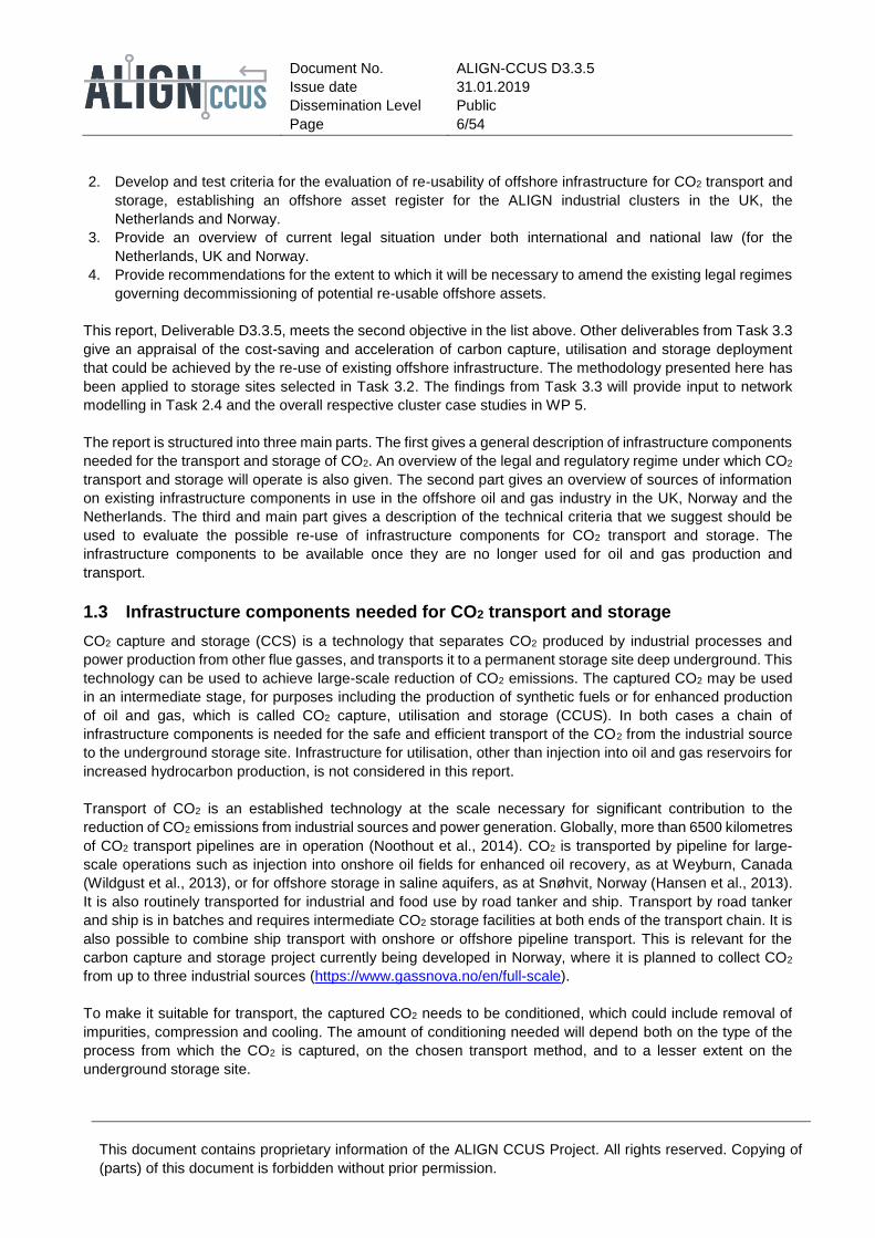
A CO2 transport and storage chain consists of the following infrastructure components: onshore and offshore
pipelines; shipping facilities; platforms; subsea manifolds. These are shown in Figure 1.1 and Figure 1.2, and
are outlined in more detail in the following text sections. Appendix A contains further details on the
infrastructure used today in the offshore oil and gas industry.
Figure 1.1 Components in a CO2 capture, transport and storage chain. Adapted from an illustration in the
One North Sea report (Element Energy, 2010). Components explained in the text are A:
receiving stations; B: compressor stations; C: onshore and offshore pipelines; D: offshore risers;
E: transport ships; F: port pipeline receiving station.
Document No.
Issue date
Dissemination Level
Page
ALIGN-CCUS D3.3.5
31.01.2019
Public
8/54
This document contains proprietary information of the ALIGN CCUS Project. All rights reserved. Copying of
(parts) of this document is forbidden without prior permission.
Figure 1.2 Components in an offshore CO2 transport and storage chain. Adapted from an illustration in the
One North Sea report (Element Energy, 2010). Components explained in the text are C:
offshore pipelines; D: offshore risers; E: transport ships; G: offshore unloading system; H:
platform foundations; I: platform (topside facilities); J: subsea manifolds.
1.3.1 Onshore and Offshore Pipelines
• Receiving station(s), A on Figure 1.1. This is where the supply of CO2 from one or more sources is
gathered before being transported to an offshore storage site. The design of the station could vary
considerably depending on the type and number of industrial sources for the CO2 stream, ranging from
a single large source to many small and different sources. The station would also contain metering
equipment.
• Compressor station(s), B on Figure 1.1. This consists of compressors to boost the pressure of the CO2
stream to meet the minimum pressure required for transport all along the pipeline.
• Pipelines, C on Figure 1.1 and Figure 1.2. Used to transport the CO2 stream from the station to the
offshore storage site. May have connections to allow branching of pipelines and valves to control the
flow of the CO2.
• Offshore risers, near D on Figure 1.1 and Figure 1.2. Piping for transporting the CO2 between
equipment at the seabed (for example the pipeline) to the platform.
1.3.2 Shipping facilities
The components of infrastructure for ship transport of CO2 (E on Figure 1.1 and Figure 1.2), apart from the
ships themselves, will depend on whether the unloading is to an onshore facility, or offshore.
• Ships or barges. Transport of CO2 by ship is an established technology (ZEP, 2017), although the
transport conditions vary by project. Barges for CO2 transport are not yet in use but could be an
interesting option for transport from inland industrial plants to offshore storage.
• Port pipeline receiving station, F on Figure 1.1. CO2 from different sources is collected, treated if
necessary, and the flow is monitored, as for the pipeline receiving station.
• Port buffer storage. Temporary storage system to accommodate the batch-wise delivery of CO2 by
ship.
• Port loading/off-loading facilities. These facilities connect the onshore buffer storage with the CO2
transport ships.
• Offshore unloading system, G on Figure 1.2. System to unload CO2 from a ship to a well for injection
into a storage site. This will include a pipe to physically connect the ship to the well and facilities for

Document No.
Issue date
Dissemination Level
Page
ALIGN-CCUS D3.3.5
31.01.2019
Public
9/54
This document contains proprietary information of the ALIGN CCUS Project. All rights reserved. Copying of
(parts) of this document is forbidden without prior permission.
heating and compression of the CO2 stream to the conditions required for injection into the reservoir.
The exact system will be specific to a given location.
Several feasibility studies (for example Iso-Tryykäri et al. (2011) and ZEP (2011)) have concluded that
transport of CO2 by ship will be more economical than transport by offshore pipeline when the transport
distances are large, and the transported amounts are relatively small. This is also the case for the CCS project
currently being developed in Norway (https://www.gassnova.no/en/full-scale), where the longest part of the
CO2 transport will be by ship.
1.3.3 Offshore platforms and subsea manifolds
Offshore platforms provide space and power connections for the equipment needed to operate and maintain
the transport and storage of CO2. This will include wells for injecting the CO2 into the reservoir, maintenance
facilities for the transport infrastructure, and compressors for increasing the pressure of the CO2 stream to the
necessary injection pressure.
The platform and subsea infrastructure comprise the following components:
• Platform foundation, H on Figure 1.2. This structure supports the platform deck. Several possible
engineering solutions are in use in the oil and gas industry, from floating steel structures to concrete
shafts firmly anchored on the sea bottom.
• Topside facilities, I on Figure 1.2. Equipment on the platform deck including wellheads, maintenance
facilities, connection to the CO2 pipeline, metering instruments, accommodation and safety apparatus.
• Wells. A shaft from the platform to transport the CO2 to the reservoir. See Appendix A.5 for further
detail on the well design.
• Subsea manifolds, J on Figure 1.2. Hardware used to route the CO2 flow subsea. Subsea installations
must be remotely operated from shore or from a nearby platform.
1.3.4 New installations or re-use
Most of the necessary CO2 transport and storage infrastructure components can already be found in use for
oil and gas operations. Offshore hydrocarbon infrastructure is built to rigorous design requirements and
construction standards developed over the last fifty years. Some components, in particular those that depend
on the physical properties of CO2 stream or the transport method, such as components for intermediate storage
buffers and ship transport, will require special design. Other components may require modification to ensure
chemical compatibility with CO2, for example some of the materials used in pipeline valves.
Re-use of existing infrastructure components that have been in service for oil and gas production and transport
is, in many situations, possible due to the similar design requirements, as will be discussed in Chapter 3.
However, for each case it will be necessary to meet a number of technical criteria, as well as a number of legal
issues, before being considered safe and available for re-use with CO2 transport and storage. The legal
framework will be briefly summarized in the next section.
1.4 Legal framework
The legal framework for offshore CCS activities is codified in different pieces of legislation and regulations.
These codifications are made on multiple levels: international, European and national. In order to understand
the national legislation, it is important to see how national legislation is influenced by European and
international legislation. In this section, a brief overview is presented of the relevant legislation on these levels.
At the international level, treaties and conventions are concluded between states to regulate a specific subject.
These treaties are made on the basis of negotiations between states and require consensus to be concluded.

Document No.
Issue date
Dissemination Level
Page
ALIGN-CCUS D3.3.5
31.01.2019
Public
10/54
This document contains proprietary information of the ALIGN CCUS Project. All rights reserved. Copying of
(parts) of this document is forbidden without prior permission.
International treaties therefore require significant time to be concluded and the level of detail is mostly not very
high.
At the European level, legislation is made through the legislative process that is found in the treaties governing
the European Union.2 The European Union is a supranational institution with its own legislative process. This
legislative process is not based on consensus of unanimity, but on majority voting. This means that opponents
of a legislative proposal can be overruled in the voting process, thereby increasing the chance of
comprehensive and complex legislation being adopted. European legislation3 comes in different forms, the
most important being the directives and regulations. Directives are instructions to the member states to adopt
legislation to reach the goals stated in the directive. The regulation has direct application and requires no
implementation by the member states. In addition to these legal instruments there are also additional ‘soft
instruments’ such as guidance documents from the European Commission. In these guidance documents the
European Commission explains how the provisions of the directives/regulations are to be interpreted and
applied. Finally, there is the case law of the European Court of Justice that is an important source of law.4
At the national level, legislation is made by the legislature of the national state. It is however important to bear
in mind that national legislation has a layered structure, there is the ‘primary’ statutory legislation that is made
by parliamentary involvement and there is ‘secondary’ delegated legislation that is made by the executive. In
addition to legislation there is also policy such as the licensing policy. Once the government starts giving out
licences to perform a certain activity, the provisions and regulations contained in the licences are indicative for
how the national law is to be understood and applied.
Between these levels there is an interaction as standards from a higher level are implemented and worked out
in more detail in the legislation of a lower level. With regard to offshore CCS activities this interaction can be
seen with regard to the prevention of pollution. Under international law, states are obliged to impose measures
to prevent pollution of the sea. Under EU legislation several directives have been enacted to have the member
states implement legislation to prevent pollution at sea. Additionally, there can also be interaction during the
licensing procedure. Some licensing procedures, instituted on the basis of EU legislation, require that a draft
licence is to be send to the European Commission for review before the national competent authority can hand
out the definitive licence to the applicant.
1.4.1 International law
The main treaty governing activities at sea is the United Nations Convention on the Law of the Sea (UNCLOS)
of 1982. This convention regulates the rights of (coastal) states in the sea, such as the sovereign right for
drilling and the construction of offshore installations, and the obligations of the states with regard to the
environmental preservation of the sea. This convention has an international scope as it has been signed and
ratified by most states, or has been accepted as the law of the sea on the basis of customary law.
In addition to UNCLOS which acts as the constitution of the sea there are numerous conventions dealing with
specific matter such as environmental protection. The London Protocol (1996) is relevant for CCS activities.
The London Protocol prohibits dumping, which initially included the storage of carbon dioxide in the subsoil,
but the storage of carbon dioxide in the subsoil is no longer considered dumping after an amendment to the
2 These treaties are the Treaty on European Union (TEU) and the Treaty on the Functioning of the European Union (TFEU).
3 Legislation made by the European Union is referred to a secondary legislation, whereas the treaties of the EU are referred to as primary legislation.
4 To date, there is no case of law dealing directly with CCS activities. However, there is a case of the European Court of Justice on the 'storage' of CO2 in calcium carbonate that could be relevant for the CCS industry: C-460/15 – Schaefer Kalk ECLI:EU:C:2017:29.

Document No.
Issue date
Dissemination Level
Page
ALIGN-CCUS D3.3.5
31.01.2019
Public
11/54
This document contains proprietary information of the ALIGN CCUS Project. All rights reserved. Copying of
(parts) of this document is forbidden without prior permission.
protocol in 2006 (Art. 4(1) & Art. 1(8) of Annex 1 London Protocol). The London Protocol initially also prohibited
cross-border transport of carbon dioxide for injection in the offshore area of another coastal state, an
amendment to lift this barrier was adopted in 2009 (Art. 6 London Protocol).5
In addition to the international conventions there are regional conventions6, in the case of the North Sea region
the relevant convention is the OSPAR convention. The OSPAR (Oil Spill Prevention, Administration and
Response) convention of 1992 deals with environmental protection in the North-East Atlantic. The OSPAR
convention prohibits the dumping of waste in the sea. The injection of carbon dioxide in the subsoil is not
considered dumping (Art. 3 of Annex III OSPAR convention).7 Additionally, two Decisions8 were made under
the OSPAR convention with regard to offshore CCS activities: OSPAR Decision 2007/1 to Prohibit the Storage
of Carbon Dioxide Streams in the Water Column or on the Sea-bed; OSPAR Decision 2007/2 on the Storage
of Carbon Dioxide Streams in Geological Formations. These decisions contain further guidelines for offshore
CCS activities which the national states have to take into account.
The international conventions provide general rules on CCS activities and the preservation of the environment.
These general rules are supplemented by international standards/guidelines on specific activities. These
standards/guidelines are drafted by specialists organised in an international platform, like the International
Maritime Organization (IMO). In 2012, the IMO published specific guidelines for the assessment of carbon
dioxide for disposal into sub-seabed geological formations.
1.4.2 European law
The European Union, on the basis of its environmental competence, has introduced legislation dealing with
CCS. The European CCS Directive (Directive 2009/31/EC) was enacted in 2009 and had to be implemented
by the EU member states in 2011. The directive is linked to the European ETS9, meaning that carbon dioxide
stored in the subsoil is not treated as an emission and therefore there is no need to cover the stored carbon
dioxide with emission allowances. The European CCS Directive aims to regulate the final part of the CCS
chain: the permanent storage in the subsoil. The directive also applies to transport of carbon dioxide through
pipelines.
The CCS Directive is based on a system whereby potential storage sites are identified (Art. 4 CCS Directive),
exploration permits are granted to explore storage sites (Art. 5 CCS Directive) and finally storage permits are
granted to permanently store carbon dioxide in the subsoil (Art. 6 CCS Directive). For each stage in the process
there are detailed rules and the applicant for a storage licence is under the obligation to perform a number of
studies and to draft several proposals for plans. Such plans include a monitoring plan, a corrective measures
plan and a provisional post-closure plan (Art. 7 CCS Directive). All of these proposals have to be approved by
the competent national authority. The goal of this detailed planning is to remove as many risks as possible
before the start of CCS activities. Additionally, the CCS Directive imposes strict criteria on the CCS operator
with regard to technical competence, the competence of the employees and financial capacity to perform the
storage activities. The last stage in the CCS storage project, i.e. site closure and transfer of liability, is one of
the contested parts of the CCS Directive. Once the storage location is fully injected the operator is under the
obligation to permanently close the storage location (Art. 17 CCS Directive). The national competent authority
will monitor the site and if necessary perform corrective measures. The cost for such corrective measures will
5 Although the amendment was passed it still has to be ratified by a number of states.
6 These regional conventions are part of international law but have regional application.
7 Although the injection of carbon dioxide was initially considered illegal, this prohibition was lifted in 2007 through an amendment of Annex III.
8 Decisions provide for further standards and guidelines and are adopted by the contracting parties (Art. 13 OSPAR convention).
9 Emission Trading Scheme.

Document No.
Issue date
Dissemination Level
Page
ALIGN-CCUS D3.3.5
31.01.2019
Public
12/54
This document contains proprietary information of the ALIGN CCUS Project. All rights reserved. Copying of
(parts) of this document is forbidden without prior permission.
be recovered from the operator. The operator will remain responsible for the storage site until the transfer of
responsibility takes place (Art. 18 CCS Directive). This transfer can only take place when there is certainty that
the carbon dioxide is permanently stored or when a minimum period of 20 years has elapsed. Additionally, the
operator has to make a financial contribution to the competent authority to cover potential future cost to monitor
the site (Art. 20 CCS Directive).
The provisions of the CCS Directive provide the instructions on how the permitting procedure is to be executed.
Many of the material requirements are not to be found in the core provisions of the CCS Directive itself, but in
the two annexes to the directive. The first annex provides the criteria for the characterisation and assessment
of the potential storage complex. The second annex lies down the criteria for the monitoring plan. The annexes
can be amended by the European Commission without the need for repealing the whole CCS Directive. The
criteria for site selection and the monitoring plan can thereby be updated by the European Commission in the
future when necessary.
In addition to the text of the CCS Directive and its annexes, the European Commission published four guidance
documents (European Commission, 2011). These documents contain information on how the provisions of the
CCS Directives are to be interpreted and implemented by the member states.
The CCS Directive was evaluated in 2015 (European Commission, 2015), but due to a lack of CCS activities
the European Commission could not state whether the directive was effective. At the time it was assumed the
lack of CCS activities could not be blamed on the functioning of the directive and the CCS Directive was
deemed to be performing adequately.
1.4.3 National law and regulations
On the national level, CCS activities in Norway, the Netherlands and the United Kingdom is regulated through
the mining legislation or dedicated CCS legislation. Because the material requirements for the licensing
procedure are derived from the CCS Directive this paragraph will only highlight the national particularities.
The implementation of the CCS Directive in Norwegian law was not straightforward because Norway is not
part of the European Union. However, Norway is part of the European Economic Area and the CCS Directive
is applicable to European Economic Area.10 The Norwegian legal framework for CCS takes a dualistic
approach. Firstly, there are stand-alone CCS activities which are governed through the Continental Shelf Act
and the CCS Regulations. Secondly, there are CCS activities that are combined with hydrocarbon extraction
which is legislated through the Petroleum Act. One of the main differences between the Petroleum Act regime
and the CCS Regulations regime is the different method of site selection. Under the CCS Regulations, the
development starts on a blank canvas. Surveys and exploratory research/drilling have to be conducted in order
to identify potential locations. The need for such exploration does not exist with hydrocarbon reservoirs that
are in production. The specifications of the reservoirs are well known to the operator, so only an additional
investigation into whether the reservoir is suitable for carbon dioxide storage is necessary (Section 30d
Petroleum Regulations). Applications for exploration and storage permits have to be made at the Ministry of
Petroleum and Energy which is the competent authority.
In the Netherlands, CCS activities are regulated through the Mining Act and the delegated legislation that can
be found in the Mining Decree. The competent authority for granting exploration and storage permits is the
Minister of Economic Affairs and Climate. The implementation of the CCS Directive in the Netherlands went
smoothly owing to the fact the Dutch Mining Act already contained provisions on the storage permits for natural
gas.
10 To this end the EEA Agreement with the EEA Joint Committee’s Decision of 15 June 2012 was amended to include the CCS Directive.

Document No.
Issue date
Dissemination Level
Page
ALIGN-CCUS D3.3.5
31.01.2019
Public
13/54
This document contains proprietary information of the ALIGN CCUS Project. All rights reserved. Copying of
(parts) of this document is forbidden without prior permission.
The CCS Directive is implemented in the UK through an amendment of the Energy Act 2008 in 2011. Chapter
3 of that act provides the legal framework for the storage of carbon dioxide in the subsoil. This act applies to
onshore and offshore storage in the United Kingdom Continental Shelf (Section 17 & 33 Energy Act 2008).
The competent authority is determined by the location of the storage site. In locations not controlled by the
Scottish authorities, the Oil and Gas Authority is the competent authority. Locations under Scottish authority
are under the control of the Scottish Ministers (Section 18(1) Energy Act). In addition to the licence the
developer needs to conclude a lease with the Crown Estate (Section 18(3) Energy Act). The application for
the licence must be made in writing at the Department for Business, Energy and Industrial Strategy (Section 3
Storage of Carbon Regulations). The licence requirements are laid down in The Storage of Carbon Dioxide
(Licensing etc.) Regulations 2010. The system works in two stages: the licensing stage and the permitting
stage. The licence is needed to allow the conduct of exploratory activities. The permit is needed for the actual
injection of carbon dioxide into the subsoil.
The UK territorial waters and exclusive economic zone are governed and managed by a number of statutory
bodies that span activity sectors (e.g. oil and gas, fisheries, renewable energy), conservation and environment
(devolved administrations and national bodies), and health and safety. The legal and regulatory system allows
for flexible oversight and permitting, particularly of co-located activities, however it relies on the interactions
between the mandated statutory bodies. Hence, re-purposing of infrastructure in place of de-commissioning
will require advance planning and engagement with multiple authorities several years before it will be possible
to have the re-use activities licenced. Furthermore, a number of regulatory permissions will be required before
geological storage rights will be obtainable to replace oil and/or gas production rights.
All of the national regimes apply a system whereby CCS activities are allowed to take place on the basis of a
permit. It is important to bear in mind that although the national competent authorities have to award the
licence, the draft licence is to be sent to European Commission for review (Art. 10(1) CCS Directive). The
European Commission shall issue a non-binding opinion on the draft permit, but if the competent authority of
the member state deviates from the opinion it has to state its reasons (Art 10(2) CCS Directive). To date, two
reviews by the European Commission have been published (European Commission, 2012; 2016)
1.4.4 Technical standards
Technical standards, such as the ISO standards, are drafted by private undertakings but may still acquire the
status of law because the legislator refers to them. In many licensing regimes the applicant for the licence must
show that the activities under the licence are performed using the Best Available Techniques (BAT) i.e.
technical standards or operating procedures. If these BAT are not laid down in delegated legislation (network
codes for example), they can be found in the standards drafted by private institutions like ISO. One issue that
might be noteworthy, is the question whether these technical standards should be made freely available. This
issue has been treated by the Dutch Supreme Court, which decided that the standards could be made available
on the condition of payment by the institute that draws up these standards.11
11 HR 22-06-2012, ECLI:NL:HR:2012:BW0393.

Document No.
Issue date
Dissemination Level
Page
ALIGN-CCUS D3.3.5
31.01.2019
Public
14/54
This document contains proprietary information of the ALIGN CCUS Project. All rights reserved. Copying of
(parts) of this document is forbidden without prior permission.
Figure 1.3 The hierarchy of legislation in terms of the level of detail.
An illustration of the hierarchy of legislation in terms of the level of detail is given in Figure 1.3. The most
relevant standards and recommended practice documents for (offshore) CO2 transport and storage
infrastructure in the North Sea area, and for consideration of potential re-use of such infrastructure, are listed
in the tables below. A broader overview of technical standards in use in offshore oil and gas activities on the
Norwegian Continental Shelf is given in Appendix B and C. The ISO standards are available (for a fee) through
national member organisations (https://www.iso.org/members.html) or through the online ISO store
(https://www.iso.org/ store.html). The American Society of Mechanical Engineers standard is available for a
fee through their online store. The DNV GL recommended practice documents are available free of charge
(DNV GL is an international accredited registrar and classification society). The download web page, however,
asks you to leave your contact information (for statistical purposes, apparently).
Table 1.1 International CCS standards.
Document code Issued Title
ISO 27913 2016 Carbon dioxide capture, transportation and geological storage:
Pipeline transportation systems
ISO 27914 2016 Carbon dioxide capture, transportation and geological storage:
Geological storage
ISO 27918 2018 Lifecycle risk management for integrated CCS projects
Table 1.2 International recommended practices for CCS. Available at https://www.dnvgl.com/oilgas/
download/dnv-rp-j201-j202-j203-dnv-oss-402.html.
Document code Issued Title
DNVGL-RP-F104 November 2017 Design and operation of carbon dioxide pipelines. (Replaces
DNVGL-RP-J202 from April 2010.)
DNVGL-RP-J203 June 2017 Geological storage of carbon dioxide

Document No.
Issue date
Dissemination Level
Page
ALIGN-CCUS D3.3.5
31.01.2019
Public
15/54
This document contains proprietary information of the ALIGN CCUS Project. All rights reserved. Copying of
(parts) of this document is forbidden without prior permission.
Table 1.3 International standards related to material selection in a CO2 environment.
Document code Issued Title
ISO 17348 New Materials Selection in CO2 Environment for casing, tubing and
downhole equipment
ISO 17349 New Streams containing high levels of CO2
Table 1.4 Relevant international standards for oil and gas industry
Document code Issued Title
DNVGL-ST-F101 December 2017 Submarine pipeline systems. Available at
https://www.dnvgl.com/oilgas/download/dnvgl-st-f101-submarine-
pipeline-systems.html.
ISO 13623 2017 Petroleum and Natural Gas industries –
Pipeline Transportation Systems.
ASME B31.4 2016 Pipeline Transportation Systems for Liquid and Slurries. Available
at https://www.asme.org/products/codes-standards/b314-2016-
pipeline-transportation-systems-liquids.

Document No.
Issue date
Dissemination Level
Page
ALIGN-CCUS D3.3.5
31.01.2019
Public
16/54
This document contains proprietary information of the ALIGN CCUS Project. All rights reserved. Copying of
(parts) of this document is forbidden without prior permission.
2 North Sea oil and gas infrastructure
For consideration of potential re-use of existing offshore oil and gas infrastructure for CO2 transport and storage
one of the first questions that needs to be answered is ‘which infrastructure components exist and are in use
today?’ Norway, the UK and the Netherlands all maintain public registers of such infrastructure, at a level of
detail that enables at least a first screening for potential re-use for CO2 transport and storage. The information
available in each of the countries is described in the following sections.
2.1 Norway
The Norwegian Petroleum Directorate (NPD) provides online access to basic infrastructure information at the
Norwegian Continental Shelf via their web site http://www.npd.no/factpages. They also provide maps via
http://gis.npd.no/factmaps/html_21/ and http://www.norskpetroleum.no/.
Basic offshore pipeline information is available from http://factpages.npd.no/factpages/ by selecting the TUF
tab (abbreviation for ‘Transportation and Utilisation Facilities’). The associated metadata are listed in Table
2.1. A map of the pipelines at the Norwegian Continental shelf is given in Figure 2.1 (from
http://www.norskpetroleum.no/).
Table 2.1 NPD web page: Metadata for pipelines at the Norwegian Continental Shelf (non-exhaustive).
Heading Description
Pipeline name NPD's official name of pipeline.
Map label Name used in the map.
Belongs to Name of the TUF or Field to which the pipeline belongs.
Current operator Name of the company that is currently operator of the pipeline.
Current phase Current phase for the pipeline: FUTURE, REMOVED, IN SERVICE,
INSTALLATION, DECOMMISSIONED, ABANDONED IN PLACE.
Phase valid from Date from, current phase.
From facility Name of facility where the pipeline starts.
To facility Name of facility where the pipeline ends.
Main grouping Name of main grouping of pipeline: Transportation, Feeder.
Dimension [inch] Pipeline dimension in inches.
Max water depth [m] Maximum water depth in metres.
Medium Medium transported in the pipeline.
In contrast to the oil and gas fields on the Norwegian shelf, where the companies themselves are responsible
for the operations, the gas pipeline system is more directly controlled by the authorities. The reason for this
is that the gas transport system is a natural monopoly and is central to Norwegian petroleum activities. An
important consideration for the authorities is to ensure equal access to capacity in the system on the basis of
companies' needs. Furthermore, the tariffs payable for access to the infrastructure must be reasonable.
Another important consideration is to ensure that the Norwegian gas transport system operates efficiently, and
that the system is developed to meet future needs. The oil transport system is not as closely regulated as
the gas transport infrastructure, mainly because pipeline transport is a less important part of the value chain
for oil (from http://www.norskpetroleum.no/en/production-and-exports/the-oil-and-gas-pipeline-system/).
With effect from 1 January 2003, virtually all of Norway's gas transport systems were integrated in a major new
joint venture called Gassled. Gassled has no employees and is organised through various committees with

Document No.
Issue date
Dissemination Level
Page
ALIGN-CCUS D3.3.5
31.01.2019
Public
17/54
This document contains proprietary information of the ALIGN CCUS Project. All rights reserved. Copying of
(parts) of this document is forbidden without prior permission.
specific assignments. This partnership serves as the formal owner of the Norwegian gas transport
infrastructure (http://www.gassco.no/en/about-gassco/gassled-eng/).
Figure 2.1 Pipelines on the Norwegian Continental Shelf (illustration from http://www.norskpetroleum.no/)
Basic offshore facility information is available from the NPD web site, http://factpages.npd.no/factpages/ by
selecting the ‘Facility’ tab. The associated metadata are listed in Table 2.2.

Document No.
Issue date
Dissemination Level
Page
ALIGN-CCUS D3.3.5
31.01.2019
Public
18/54
This document contains proprietary information of the ALIGN CCUS Project. All rights reserved. Copying of
(parts) of this document is forbidden without prior permission.
Table 2.2 NPD web page: Metadata for facilities at the Norwegian Continental Shelf (non-exhaustive).
Heading Description
Fixed or moveable Indicator which tells if the facility is regarded as fixed or moveable.
Name Name of the facility used by NPD
Kind Kind of facility: CONCRETE STRUCTURE, CONDEEP 3 SHAFTS, CONDEEP 4
SHAFTS, CONDEEP MONOSHAFT, DORIS, FPSO, FSU, JACKET 12 LEGS,
JACKET 4 LEGS, JACKET 6 LEGS, JACKET 8 LEGS, JACKET TRIPOD, JACK-
UP 3 LEGS, JACK-UP 4 LEGS, LOADING SYSTEM, MONOTOWER, MULTI WELL
TEMPLATE, ONSHORE FACILITY, SEMISUB CONCRETE, SEMISUB STEEL,
SINGLE WELL TEMPLATE, SUBSEA STRUCTURE, TLP CONCRETE, TLP
STEEL, VESSEL.
Phase Current phase for the facility: ABANDONED IN PLACE, DECOMMISSIONED,
FABRICATION, FUTURE, IN SERVICE, INSTALLATION, LAID UP, REMOVED.
Functions Tells what functions the facility covers: DRILLING, DRILLING TEMPLATE, FIELD
CONTROL CENTER, FISCAL METERING, FLARE STACK, FLOTEL, FULL
STABILIZATION, GAS EXPORT, GAS INJECTION, GAS INJECTOR, GAS
PRODUCER, ISOLATION VALVE, LOADING BOUY, MANIFOLD, MANIFOLD
STATION, OFFLOADING, OIL PRODUCER, PIG RECIVER, PIPELINE END
MANIFOLD, QUARTER, RISER, RISER BASE, RISER SUPPORT, SEPARATION,
SILO, STORAGE, T-CONNECTION, TERMINAL, TRAWLGEAR PROTECTION,
TUNNEL, UMBILICAL SUPPORT, WATER INJECTION, WATER/GAS INJECTION,
WELLHEAD, Y-CONNECTION, PROCESSING, ACCOMMODATION, SUPPORT,
BOOSTER, DISTRIBUTION, WATER PRODUCER or a combination of these.
Geodetic datum Geodetic datum for the coordinates of the position of the facility.
RKB elevation [m] Elevation above mean sea level in metres of the rotary kelly bushing.
Water depth [m] Water depth from mean sea level in metres at well site.
Startup date The date the facility was set in production.
Design lifetime [year] The number of years for which the facility was designed.
Surface facility Indicator telling if the facility is a surface or subsurface facility.
Basic well information is available from the NPD web site, http://factpages.npd.no/factpages/ by selecting the
‘Wellbore’ tab. The associated metadata are listed in Table 2.3 and
Table 2.4 (casings).
Table 2.3 NPD web page: Metadata for wells at the Norwegian Continental Shelf (non-exhaustive).
Heading Description
Wellbore name Official name of wellbore.
Well name Official name of the parent well for the wellbore.
Type Wellbore type: EXPLORATION, DEVELOPMENT, OTHER.
Purpose Final classification of the wellbore.
Exploration wellbores:
WILDCAT, APPRAISAL.
Development wellbores:
OBSERVATION, PRODUCTION, INJECTION.
Other wellbores:
SOIL DRILLING – drilling in connection with track surveys and other subsurface
surveys to investigate the soil conditions prior to placement of facilities;

Document No.
Issue date
Dissemination Level
Page
ALIGN-CCUS D3.3.5
31.01.2019
Public
19/54
This document contains proprietary information of the ALIGN CCUS Project. All rights reserved. Copying of
(parts) of this document is forbidden without prior permission.
SHALLOW GAS – drilling to investigate shallow gas before the first 'real' drilling on
the location;
PILOT – drilling to investigate the geology and fluid connectors for location of the
main wellbore;
SCIENTIFIC – drilling according to Law of Scientific research and exploration;
STRATIGRAPHIC – drilling according to Law of Petroleum activities §2-1.
Status Status for wellbore:
BLOWOUT – a blowout has occurred in the well;
CLOSED – a development well that has been closed in a shorter or longer period;
DRILLING – the well is in the drilling phase. This can be active drilling, logging,
testing or plugging;
JUNKED – the well is finished because of technical problems;
ONLINE/OPERATIONAL – development well that is drilled. It is either ready for
production or is currently producing or injecting;
P&A – for exploration wellbores: the well is plugged and abandoned, for
development wellbores: the production/ injection in the well is stopped and the field
is closed;
PLUGGED – the development well is plugged, but the field is still active;
PREDRILLED – predrilling of the well is done;
RE-CLASS TO DEV – exploration well that is reclassified to a development well;
RE-CLASS TO TEST – exploration well that is reclassified to test production;
SUSPENDED – well that is temporary abandoned.
Content For exploration wellbores, status of discovery:
DRY, SHOWS (trace amounts of hydrocarbons), GAS, GAS/CONDENSATE, OIL or
OIL/GAS. SHOWS (GAS SHOWS, OIL SHOWS or OIL/GAS SHOWS) are detected
as fluorescent cut (organic extract), petroleum odour, or visual stain on cuttings or
cores, or as increased gas reading on the mud-loggers gas detection equipment.
For development wellbores, type of produced/injected fluid:
WATER, CUTTINGS, NOT AVAILABLE, OIL, GAS/CONDENSATE, OIL/GAS, CO2,
GAS, WATER/GAS, NOT APPLICABLE.
Subsea Indicates if the well is completed on the seabed or not.
With casing and lot Indicator telling if the wellbore has this kind of information.
Table 2.4 NPD web page: Metadata for casings and hole (non-exhaustive).
Heading Description
Wellbore Official wellbore name.
Casing type A typical wellbore will be cased with CONDUCTOR and SURFACE CONDUCTOR
types of casing in the upper section, INTERMEDIATE casing through non-reservoir
sections, and a PRODUCTION or plastic LINER types of casing, or even OPEN
HOLE, in potential reservoir sections towards final total depth of the wellbore.
Casing diameter [inch] Inner diameter of casing, in inches.
Casing depth [m] Total depth below kelly bushing, in metres, of a cased section (casing shoe).
Hole diameter [inch] Diameter of wellbore (the drill bit), in inches.
Hole depth [m] Total depth below kelly bushing, in metres, of a wellbore section drilled with a
certain diameter.

Document No.
Issue date
Dissemination Level
Page
ALIGN-CCUS D3.3.5
31.01.2019
Public
20/54
This document contains proprietary information of the ALIGN CCUS Project. All rights reserved. Copying of
(parts) of this document is forbidden without prior permission.
2.2 United Kingdom
Oil & Gas UK provide online access to basic infrastructure information regarding wells, pipelines, platforms,
and surface and sub-surface infrastructure for the UK offshore waters via the Common Data Access Limited
(CDA) website (www.ukoilandgasdata.com). Data is collected from infrastructure operators at six-month
intervals, and is intended to provide potential oil and gas developers and the shipping industry with the
positions of all known structures at the sea surface and seabed. A map of pipelines and selected onshore
terminals for the UK is shown in Figure 2.2. More detailed maps, showing current hydrocarbon fields, the
planned Goldeneye Field storage site and Southern North Sea storage sites investigated in ALIGN-CCUS
Task 3.2 are shown in Figure 2.3 and Figure 2.4. A limited level of access to these data are available to the
public, free of charge, via a map service published by the Oil and Gas Authority (OGA). Full access to the
underlying data tables currently requires a membership agreement or subscription to CDA, for which a fee
and/or eligibility criteria apply. Outlines of the data available for offshore pipelines, surface, and seabed
infrastructure are shown in Table 2.5, Table 2.6, and Table 2.7, respectively. Information typically includes the
current status of the infrastructure, the operator, and a brief description. Additional information for platforms is
available from various commercially owned databases, but no central database is available for this study.
Technical specifications such as pipeline materials are not publicly available.
Pipeline operators typically make minimal high-level information available to potential users online. The level
of information provided is set out in the Infrastructure Code of Practice published by Oil & Gas UK (Oil & Gas
UK, 2017). Links to this information are maintained by CDA, but no central database exists that can be readily
interrogated. Information made available to the public by pipeline operators in accordance with the code of
practice typically includes:
1. Oil or Gas export capacity
2. Gas compression capacity
3. Outline details of processing and treatment facilities
4. Pipeline length
5. Pipeline material (often including wall thickness and internal coating material)
6. Entry and exit fluid specifications
Further technical information beyond the disclosed high-level summary is commercially sensitive and not
readily available, and therefore must be requested directly from pipeline operators. This includes information
regarding the expected remaining lifetime of the facilities, details of ‘mothballed’ equipment that may be
available for re-use, and technical specifications for pipeline components such as valves, connections, and
maintenance sections.
The Oil and Gas Authority (OGA) provide basic information for all hydrocarbon wells drilled on the UK
Continental Shelf. The data is published under an Open Government Licence, free of charge, and is available
from the OGA Open Data website (http://data-ogauthority.opendata.arcgis.com). An outline of the data
available that are relevant to this study is listed in Table 2.8. A detailed description of the data format, including
keys to various status codes, is available in the OGA Wellbore Standard (OGA, 2017). Further technical details
relevant to re-use, such as casing and cement specifications, must be retrieved from well drilling and
completion reports on a case-by-case basis. Well data is normally released five years after the date of well
completion. Access to these reports is provided by CDA, for which membership or a subscription fee is normally
required.
Additional data relevant to this study, such as decommissioning timescales, is held by OGA but is not publicly
available, and has not been made available for this study.

Document No.
Issue date
Dissemination Level
Page
ALIGN-CCUS D3.3.5
31.01.2019
Public
21/54
This document contains proprietary information of the ALIGN CCUS Project. All rights reserved. Copying of
(parts) of this document is forbidden without prior permission.
Figure 2.2 Active hydrocarbon infrastructure (oil, gas, condensate, mixed hydrocarbons) for offshore UK.

Document No.
Issue date
Dissemination Level
Page
ALIGN-CCUS D3.3.5
31.01.2019
Public
22/54
This document contains proprietary information of the ALIGN CCUS Project. All rights reserved. Copying of
(parts) of this document is forbidden without prior permission.
Figure 2.3 Hydrocarbon infrastructure for the Central North Sea, with current hydrocarbon fields. The
Goldeneye Field storage site indicated in blue.
Figure 2.4 Hydrocarbon infrastructure for the Southern North Sea, with current hydrocarbon fields. Storage
sites investigated in ALIGN-CCUS (Task 3.2) indicated in blue.
Document No.
Issue date
Dissemination Level
Page
ALIGN-CCUS D3.3.5
31.01.2019
Public
23/54
This document contains proprietary information of the ALIGN CCUS Project. All rights reserved. Copying of
(parts) of this document is forbidden without prior permission.
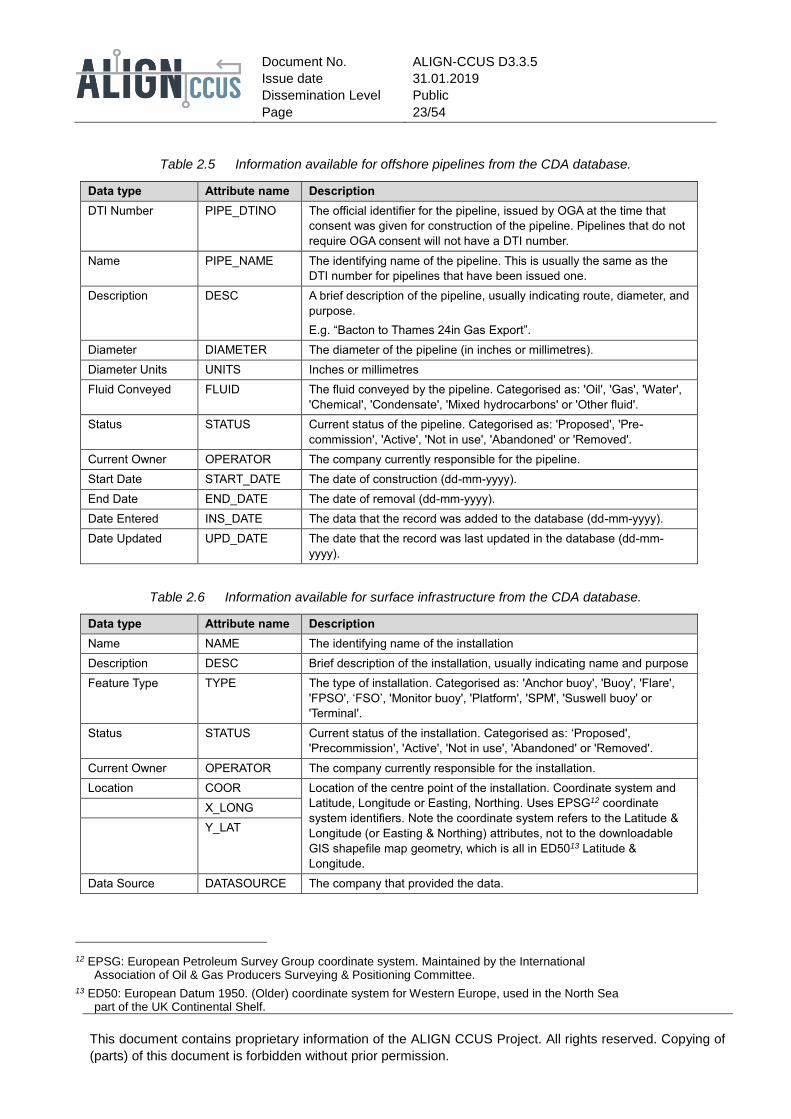
Table 2.5 Information available for offshore pipelines from the CDA database.
Data type Attribute name Description
DTI Number PIPE_DTINO The official identifier for the pipeline, issued by OGA at the time that
consent was given for construction of the pipeline. Pipelines that do not
require OGA consent will not have a DTI number.
Name PIPE_NAME The identifying name of the pipeline. This is usually the same as the
DTI number for pipelines that have been issued one.
Description DESC A brief description of the pipeline, usually indicating route, diameter, and
purpose.
E.g. “Bacton to Thames 24in Gas Export”.
Diameter DIAMETER The diameter of the pipeline (in inches or millimetres).
Diameter Units UNITS Inches or millimetres
Fluid Conveyed FLUID The fluid conveyed by the pipeline. Categorised as: 'Oil', 'Gas', 'Water',
'Chemical', 'Condensate', 'Mixed hydrocarbons' or 'Other fluid'.
Status STATUS Current status of the pipeline. Categorised as: 'Proposed', 'Pre-
commission', 'Active', 'Not in use', 'Abandoned' or 'Removed'.
Current Owner OPERATOR The company currently responsible for the pipeline.
Start Date START_DATE The date of construction (dd-mm-yyyy).
End Date END_DATE The date of removal (dd-mm-yyyy).
Date Entered INS_DATE The data that the record was added to the database (dd-mm-yyyy).
Date Updated UPD_DATE The date that the record was last updated in the database (dd-mm-
yyyy).
Table 2.6 Information available for surface infrastructure from the CDA database.
Data type Attribute name Description
Name NAME The identifying name of the installation
Description DESC Brief description of the installation, usually indicating name and purpose
Feature Type TYPE The type of installation. Categorised as: 'Anchor buoy', 'Buoy', 'Flare',
'FPSO', ‘FSO’, 'Monitor buoy', 'Platform', 'SPM', 'Suswell buoy' or
'Terminal'.
Status STATUS Current status of the installation. Categorised as: ‘Proposed',
'Precommission', 'Active', 'Not in use', 'Abandoned' or 'Removed'.
Current Owner OPERATOR The company currently responsible for the installation.
Location COOR Location of the centre point of the installation. Coordinate system and
Latitude, Longitude or Easting, Northing. Uses EPSG12 coordinate
system identifiers. Note the coordinate system refers to the Latitude &
Longitude (or Easting & Northing) attributes, not to the downloadable
GIS shapefile map geometry, which is all in ED5013 Latitude &
Longitude.
X_LONG
Y_LAT
Data Source DATASOURCE The company that provided the data.
12 EPSG: European Petroleum Survey Group coordinate system. Maintained by the International Association of Oil & Gas Producers Surveying & Positioning Committee.
13 ED50: European Datum 1950. (Older) coordinate system for Western Europe, used in the North Sea part of the UK Continental Shelf.

Document No.
Issue date
Dissemination Level
Page
ALIGN-CCUS D3.3.5
31.01.2019
Public
24/54
This document contains proprietary information of the ALIGN CCUS Project. All rights reserved. Copying of
(parts) of this document is forbidden without prior permission.
Table 2.7 Information available for sub-sea infrastructure from the CDA database.
Data type Attribute name Description
Name NAME The identifying name of the installation
Description DESC Describes the installation.
Feature Type TYPE The type of installation. Categorised as: 'Anchor', 'Anchor block',
'Anchor pile', 'Clump weight', 'Debris', 'Divertor', 'Manifold', 'Obstruction',
'Pig receiver T', 'Pipe junction', 'Protection', 'Riser base’, 'Seabed
fastener', 'Storage tank', 'Subsea buoy', 'Tee piece', 'Template',
'Towhead', 'Transponder', 'Unidentified', 'Valve', 'Wellhead' or 'Wreck'
Status STATUS Current status of the installation. Categorised as: ‘Proposed',
'Precommission', 'Active', 'Not in use', 'Abandoned' or 'Removed'.
Current Owner OPERATOR The company currently responsible for the installation.
Location COOR Location of the centre point of the installation. Coordinate system and
Latitude, Longitude or Easting, Northing. Uses EPSG12 coordinate
system identifiers. Note the coordinate system refers to the Latitude &
Longitude (or Easting & Northing) attributes, not to the downloadable
GIS shapefile map geometry, which is all in ED5013 Latitude &
Longitude.
X_LONG
Y_LAT
Data Source DATASOURCE The company that provided the data.
Table 2.8 Information available for offshore hydrocarbon wells from the OGA database. For description of
status codes, see OGA (2017).
Data type Attribute name Description
Well Registration
Number
WELLREGNO The official identifier for the well, issued by OGA upon approval to drill.
Top Hole Location TOPHOLEYDD
TOPHOLEXDD
The surface location of the well head, defined in longitude and latitude.
Platform PLATFORM The platform identifier. If the well was drilled from a platform, the
specific platform is indicated with a single upper-case letter.
Slot Number SLOTNO Platform slot number.
Original Intention ORIGINTENT Original purpose of the well (Exploration, Appraisal, or Development).
Datum Elevation DATUMELEV Elevation of the reference datum above mean sea level.
Datum Type DATUMTYPE The type of reference datum (KB, RT, GL).
Water Depth WATERDEPTH The depth to the seabed at the well location.
Spud Date SPUDDATE The date on which drilling commenced.
Completion Date COMPLEDATE The date on which the well was completed.
Operator OPERATOR The name of the company group that are responsible for the well.
Primary Target PRIMARYTAR The primary reservoir interval targeted.
Completion Status COMPLESTAT The status upon completion of the well. Categorised as: ‘AB1’, ‘AB2’,
‘AB3’, ‘Completed operating’, ‘Completed shut in’, ‘Drilling’, ‘Plugged’.
Flow Class FLOWCLASS Producing wells are assigned a ‘flow class’ based on the fluid type and
flow rate of the well.
Total Depth TVDSSDRILL
TOTALMDDRI
The total depth of the well bore in ‘true vertical depth sub-sea’ or
‘measured depth’, as recorded by the driller.
Development Type DEVTYPE For development wells, the category of production well. Categorised as:
‘Disposal’, ‘Injector’, ‘Other’, ‘Producer’.

Document No.
Issue date
Dissemination Level
Page
ALIGN-CCUS D3.3.5
31.01.2019
Public
25/54
This document contains proprietary information of the ALIGN CCUS Project. All rights reserved. Copying of
(parts) of this document is forbidden without prior permission.
2.3 The Netherlands
Existing oil and gas infrastructure for the Netherlands is listed in an annual report that is published at the site
nlog.nl. This publication lists existing platforms and pipelines, along with some details. Examples are given
below.
The Netherlands annual infrastructure report, mentioned above, gives a complete overview of the offshore
pipelines on the Dutch Continental Shelf (DCS). Table 2.9 contains a small portion of the data, also showing
the level of detail that is available.
Table 2.9 Offshore pipeline data for the DCS; this table shows a small portion of the pipelines for which
data is available at nlog.nl. Some of the rows in this example shows two pipelines transporting
separate substances, in these cases gas (g) and methanol (m).
Operator From To Diameter
(inches)
Year of
construction
Length (km) Transported
substance
Neptune L10-C L10-AP 10.75, 2.375 1974 1.1 g + m
Neptune L10-B L10-AP 10.75, 2.375 1974 7.4 g + m
NGT L10-AR Uithuizen 36 1975 179.0 g
Wintershall K13-AP Callantsoog 36 1975 120.5 g
Neptune L10-D L10-AP 10.75, 2.375 1977 1.1 g + m
Neptune L10-E L10-AP 10.75, 2.375 1977 4.0 g + m
NAM K8-FA-1 K14-FA-P 24 1977 30.9 g
The online web site nlog.nl also provides information about offshore platforms; Table 2.10 shows a small
portion of the available data. Vermeulen (2009) and Jansen et al. (2011) studied the costs involved in platform
mothballing (suspending) and modification for CO2 injection, also in abandonment of platforms. While these
results should be updated to present-day cost levels, these analyses provide the building blocks for an
estimation of the costs of using specific reservoirs (wells) and platforms for CO2 injection. The estimation of
costs should take into account a period of suspension of platform activities (‘mothballing’) and comparing the
results with, for example, abandonment and new build.
Table 2.10 Offshore platform data for the DCS; this table shows a small portion of the platforms for which
data is available at nlog.nl.
Platform Operator Year of
installation
Number of
legs
Gas / oil Role
K13-A Wintershall 1974 8 Gas Production /
compression
L10-A Neptune 1974 8 Gas Production
L10-B Neptune 1974 4 Gas Satellite
L10-C Neptune 1974 4 Gas Satellite
K14-FA-1 NAM 1975 10 Gas Integrated
L7-B Total 1975 4 Gas Integrated
K15-FA-1 NAM 1977 10 Gas Integrated
About 25 subsea completions are currently in use on the DCS. Details of some of these are included in the list
of platforms shown in Table 2.10.

Document No.
Issue date
Dissemination Level
Page
ALIGN-CCUS D3.3.5
31.01.2019
Public
26/54
This document contains proprietary information of the ALIGN CCUS Project. All rights reserved. Copying of
(parts) of this document is forbidden without prior permission.
The site nlog.nl also provides detailed information about wells on the DCS. All publicly available data can be
found, which includes well trajectory, log data, drilling reports, gas composition, water composition, etc. The
site also maintains an interactive map (https://www.nlog.nl/en/interactivs-map-original) where, among other
information, wells, platforms and pipeline locations may be plotted. An example is shown in Figure 2.5.
Figure 2.5 An example of infrastructure maps for the DCS generated by the map service at nlog.nl. In this
example existing production platforms (red dots), oil and gas fields (green/light green for
producing/undeveloped gas fields, red/pink for producing/undeveloped oil fields), and offshore
pipelines (red lines) are selected for plotting.

Document No.
Issue date
Dissemination Level
Page
ALIGN-CCUS D3.3.5
31.01.2019
Public
27/54
This document contains proprietary information of the ALIGN CCUS Project. All rights reserved. Copying of
(parts) of this document is forbidden without prior permission.
3 Methodology for re-use mapping
The design of any CO2 transport system needs to be developed contemporaneously with the design of the
connecting CO2 capture and storage sites. In particular, consideration should be given to the fluid specification,
capacity, required injection and transport pressures, and longevity of the storage project. WorleyParsons
(2013), on behalf of The Crown Estate, completed an assessment to identify the main technical issues for
using existing pipelines to transport CO2. This assessment, together with discussion in IEAGHG (2018),
provide the basis for the criteria (given below) that can be used in an initial screening to determine the suitability
of existing infrastructure for CO2 transport and storage. Quantitative bounds for these criteria will need to be
determined for each specific site, dependent on the characteristics of the CO2 stream (rate, pressure,
temperature and composition). Each part of the infrastructure would need to undergo a detailed examination
to be confident it can be safely re-used for CO2 transport and storage. The CO2 stream may contain impurities
characteristic of the separation and conditioning process (see ALIGN deliverable D2.3.1, or de Visser et al.
(2008)). These impurities will change the phase behaviour of the CO2 stream and will, for the most common
impurities, increase the pressure necessary to maintain a single-phase, dense CO2 stream. Two-phase flow
is generally not wanted in pipeline transport, since it makes it necessary to install slug catchers and the like to
maintain a steady flow. There is also a risk of drop-out of a (corrosive) liquid phase in lower-lying sections of
the pipeline. To avoid two-phase flow higher operating pressures are needed to maintain efficient (dense-
phase) CO2 pipeline transport (de Visser et al., 2008). In addition to changing the optimal pressure, impurities
in the CO2 fluid may influence the compression power needs and the risk for corrosion and hydrate formation.
Following a study on CO2 storage in depleted oil and gas fields (IEAGHG, 2017) IEAGHG also commissioned
a study on the re-use of existing facilities at oil and gas fields in the CO2 storage operation (IEAGHG, 2018).
The study used examples from a number of depleted oil and gas fields on the UK Continental Shelf in the
North Sea and the Irish Sea. The 2018 report concluded that all elements of oil and gas infrastructure have
the potential for re-use with CO2 transport and storage. However, it was also concluded that it is not feasible
to define generic specifications to assess suitability of infrastructure for re-use, as that will depend on the
specific requirements of each project.
The window of opportunity to adapt existing above-ground oil and gas infrastructure for re-use with CO2 may
be very narrow (Element Energy, 2010), due to legislation that typically requires infrastructure to be removed
after hydrocarbon production has ceased. The development of re-use plans has to be timed with the
development of decommissioning plans for oil and gas infrastructure. The gas export pipeline and the platform
were considered suitable for re-use for a CO2 storage project injecting into the depleted Goldeneye Gas
Condensate Field (Shell, 2016). The end stages of production from the field coincided with efforts to find
suitable candidates for full-chain CCS demonstration projects. Following the end of production, the pipeline
from the field to shore was cleaned and filled with a corrosion-inhibiting fluid. However, as the funding for the
development of a CCS project was withdrawn the prospects for a project implementation to actually re-use the
facilities became uncertain. The operator has, therefore, now submitted decommissioning plans for the field
that includes complete removal of platform topside and jacket.
Technical criteria that can be used to screen infrastructure for re-use with CO2 (WorleyParsons, 2013;
IEAGHG, 2018) are discussed in more detail in the next sections and include:
• availability (location and timeline);
• lifespan;
• integrity;
• operating pressure;
• capacity; and
• materials.

Document No.
Issue date
Dissemination Level
Page
ALIGN-CCUS D3.3.5
31.01.2019
Public
28/54
This document contains proprietary information of the ALIGN CCUS Project. All rights reserved. Copying of
(parts) of this document is forbidden without prior permission.
Emerging results on the testing of the methodology by application to infrastructure in Norway, the UK and the
Netherlands and recommendation of the order of criteria application are also presented.
3.1 Availability
Availability of offshore oil and gas pipelines and production facilities for re-purposing to a CO2 transport and
storage service will be influenced by a number of technical and non-technical factors and also complex
regulatory and commercial interactions. Furthermore, conversion of the subsurface reservoirs that have been
licenced for oil and/or gas production to permanent CO2 storage will require a substantial amount of geoscience
and engineering work. Such work would be in advance of receiving a permit to undertake the storage activity.
Under the EU Directive receipt of a storage permit is dependent on a number of factors that may be influenced
by the technical specifications of any existing facilities and wells in place.
Legal and other non-technical criteria relevant for assessing re-use potential will be dealt with in a separate
ALIGN-CCUS report, D3.3.4 (scheduled in August 2019). For illustration some of the non-technical criteria that
need to be investigated when assessing the availability of infrastructure for re-use are listed below:
• Ability to transfer ownership/licences from existing production joint ventures to CO2 joint ventures with
different ownership structures;
• Statutory restrictions on allowing co-location and/or overlapping of different economic activities;
• Ability to obtain joined-up approvals from multiple statutory authorities responsible for permitting,
licensing and leasing;
• Statutory and contractual handling of legacy and residual risks, and legacy liabilities from oil and gas
production operations;
• Statutory mandates for optimising oil and gas production;
• Environmental impact assessments and strategic environmental assessments; and
• Restrictions, requirements and impact of marine and conservation planning.
These non-technical criteria demonstrate the complexity of the decisions and licensing for re-purposing to a
CO2 storage service.
The availability of existing infrastructure for re-use for transport and storage of CO2 is dependent on the
remaining economic life of connected hydrocarbon fields and any plans for future near-field developments.
Development of nearby discoveries is strongly dependent on the development of new technical solutions and
on economic conditions, such as oil price, and is therefore very uncertain even for existing discoveries.
Information pertaining to the remaining lifespan of oil and gas fields and their associated infrastructure is
commercially sensitive and would need to be sourced from the individual operators or the licensing authorities.
The timeline of availability for existing oil and gas infrastructure is therefore associated with many uncertainties.
Re-use for a CO2 transport and storage network ideally needs to be considered when decommissioning is
being planned. Re-use of a pipeline that has already been decommissioned may be possible, although the
integrity of the pipeline may have been compromised since the time of decommissioning. Any future use would
require extensive inspection, reconnection and testing (IEAGHG, 2018). At the end of field production the gas
export pipeline for the Goldeneye Field was cleaned and filled with a preserving liquid, but an integrity
inspection with intelligent pigging was not performed, as this was considered to be a task for a possible future
entity wishing to re-use the pipeline.
The location of an existing piece of infrastructure in relation to a potential storage site is one of the strongest
screening factors. This is the case in the Netherlands, where depleted gas fields are the first choice for storing
CO2. The first storage projects are designed around a platform and wells that are to be re-used, while a new

Document No.
Issue date
Dissemination Level
Page
ALIGN-CCUS D3.3.5
31.01.2019
Public
29/54
This document contains proprietary information of the ALIGN CCUS Project. All rights reserved. Copying of
(parts) of this document is forbidden without prior permission.
transport pipeline is being designed. Re-locating an existing pipeline involves risks of compromising its
integrity that are too large and re-use would probably be more expensive than installation of new equipment.
Exceptions to this could be in-field flexible pipelines, but these are often custom-made to specific lengths and
cannot easily be re-purposed to a different transport length.
The pipeline route itself could also represent a value for re-use, even if the existing pipeline cannot be used.
Time-consuming surveying work may be reduced if an existing route can be re-used.
It is important to be aware of two distinctly different starting points that discussions of availability could have.
One starting point is the assessment of re-use possibilities for a depleted oil and gas field, that has a reservoir
and some infrastructure that could potentially be re-used for other purposes. This starting point is considered
for the cases in the IEAGHG (2018) report. An availability assessment for the production and transport
infrastructure is then mostly concerned with evaluation of the non-technical issues in the bullet point list above.
However, as previous examples have shown, for these cases the availability of suitable full-chain CCS projects
with economic viability have been the show-stoppers thus far. The other starting point, which is more relevant
for the ALIGN-CCUS cases, is that an industry cluster is investigating various opportunities for reduction of
CO2 emissions. The main availability issue is then the location of any existing oil and gas infrastructure, and
whether the present use of the infrastructure will end within a suitable time window.
3.2 Lifespan
Infrastructure near the end of its service life has much less potential for re-use. The remaining lifespan of
existing infrastructure needs to be at least equal to the expected period of the CO2 injection and is constrained
by the integrity of the infrastructure. A typical estimate for the useful life of offshore infrastructure is forty years
(Pale Blue Dot Energy Ltd., 2016). However, the remaining lifespan of existing infrastructure may be more or
less than expected, and dependant on the standard to which it has been maintained to date. This can be
determined via a full assessment of the integrity. Depending on the assessment results, options for extension
of the remaining lifetime of the infrastructure may be considered.
For the main trunk pipelines, e.g. the Norwegian export gas pipelines, the design lifetime is typically longer
than for in-field pipelines and field-to-hub pipelines. However, the trunk pipelines are also least likely to be
available in the foreseeable future due to their central function and future oil and gas production foreseen in
the area.
For platforms the foundation could have a longer remaining lifespan than the topside equipment, but the
feasibility of removing and replacing the topside and leaving in place the foundation would need to be
evaluated. In the Peterhead CCS project, the Goldeneye Field platform was designed for a lifetime of 20 years
and used for about 10 years for gas production. The CCS project considered it feasible to extend the lifetime
of the platform to 35 years to suit the planned CCS operation (Shell, 2016).
3.2.1 'Mothballed' infrastructure
Re-use of infrastructure with CO2 may not always directly follow the end of hydrocarbon production. If
infrastructure is to be re-used, a period of suspension may be required. While a period of a few years may be
feasible, in terms of maintaining platforms and wells, the associated cost may become prohibitive for periods
of a decade or longer. In the latter case, decommissioning existing installations and constructing new facilities
(wells, platform or subsea installation) may be more cost effective. An additional benefit of new facilities is that
these can be tailored to the needs of the CO2 injection project.

Document No.
Issue date
Dissemination Level
Page
ALIGN-CCUS D3.3.5
31.01.2019
Public
30/54
This document contains proprietary information of the ALIGN CCUS Project. All rights reserved. Copying of
(parts) of this document is forbidden without prior permission.
3.3 Integrity
The integrity of the infrastructure will determine the lifespan and operating pressure of the asset(s) for CO2 re-
use. For pipelines, this will be assessed through a detailed inspection of the internal and external conditions
to include: wall thickness verification; identification of any defects such as fractures; the corrosion protection
system. For the storage site, the physical condition of existing hydrocarbon wells (whether still in use or
abandoned) needs to be considered to ensure the safe containment of injected CO2. Additionally, the structural
integrity of any platform needs to be included in the assessment. Integrity assessments are not normally part
of the end-of-life plans for an oil and gas production operation, which makes the assessment of re-use
opportunities more uncertain.
3.4 Operating pressure
Pure CO2 at atmospheric pressure will be in gas phase at temperatures above about −78°C, and a solid (dry
ice) for temperatures below this. When pressure is increased to about 5.2 bar absolute (bara), CO2 can also
exist in liquid phase. The transition from gas to liquid occurs at about −53°C at 6 bara, −20 °C at 20 bara and
increases to about 29°C at 70 bara. The line separating liquid and gas is the liquid-gas equilibrium line, which
ends in the critical point (around 31°C, 73.8 bara). Above the critical temperature a separate liquid phase can
no longer exist, and the CO2 transitions from a low-density gas-like substance at low pressures to a high-
density liquid-like substance at high pressures (above 74 bara). Conversely, above the critical pressure there
is no phase change from liquid to gas as the temperature is increased from ambient temperature to the high
temperatures encountered in the subsurface. A phase diagram is shown in Figure 3.1.
Figure 3.1 Phase diagram of pure CO2 (source: https://2012books.lardbucket.org/books/principles-of-
general-chemistry-v1.0m/index.html). The green rectangle shows typical onshore pipeline
transport conditions. The red trapezoid shows possible low-pressure sea-bottom pipeline
transport conditions for liquid-state (and high-density) CO2. Pressure in atmospheres where 1
atmosphere (atm) is equal to 1.01325 bar absolute.

Document No.
Issue date
Dissemination Level
Page
ALIGN-CCUS D3.3.5
31.01.2019
Public
31/54
This document contains proprietary information of the ALIGN CCUS Project. All rights reserved. Copying of
(parts) of this document is forbidden without prior permission.
For multicomponent systems, such as CO2 with significant amounts of impurities, the liquid-gas equilibrium
curve widens into a so-called ’phase envelope’. Most relevant impurities for CCS will cause the maximum
possible pressure for co-existence of a liquid-gas system to increase, which means that a pipeline needs to
operate at higher pressures to be certain of single-phase transport.
In onshore pipelines, CO2 is generally transported in the dense phase at temperature and pressure ranges
between 12°C and 44°C and 85 and 200 bara (the green rectangle in Figure 3.1). The lower pressure limit is
set by the phase behaviour of CO2 and should be sufficient to maintain single phase conditions while the upper
pressure limit is mostly due to economic and material concerns. Regarding the temperatures, the upper
temperature limit is determined by the compressor station discharge temperature and the temperature limits
of the external pipeline coating material. The lower limit is determined by the winter ground temperature of the
surrounding soil (Wetenhall et al., 2014).
For offshore pipelines, where sea bottom temperatures can drop below 10°C, it should be noted that it is also
possible to transport CO2 at high density in the liquid phase at pressures above the saturation pressure (45
bara at 10°C) (the red trapezoid in Figure 3.1). This would make qualification of an existing pipeline for CO2
transport easier. A transport pressure of as low as 60 bar should ensure sufficient injectivity at relevant
reservoir depths down to about 3 km. The advantage with this is that less compression work will be needed.
Note that this pressure of 60 bar refers to the injection platform or injection wellhead. High concentrations of
impurities will alter the saturation and critical pressures, and may require higher operating pressure (de Visser
et al., 2008; Wetenhall et al., 2014).
The maximum required working pressure for CO2 transport is controlled by the pipeline diameter and length,
the elevation profile of the pipeline and the required injection pressure at the storage site (which may increase
over time, see the next text section). The design pressure of an existing pipeline should be available from the
operator but the safe working pressure for CO2 transport may need to be adjusted after completion of the
integrity assessment, particularly the wall thickness verification.
To avoid the need for compression offshore, there needs to be a sufficient differential between the bottom hole
pressure and the pressure in the reservoir. The well needs to be able to maintain the required injection
pressures for the duration of the storage project.
3.5 Capacity
3.5.1 Pipeline capacity
The operational capacity of a pipeline is mainly determined by its length, diameter and the applied pressure
difference when other factors such as temperature and friction coefficients are kept constant. Pipeline capacity
scales with pipeline diameter D approximately as Da, with value of a approximately 2.6, and decreases with
increasing length L approximately as 1/Lb, with value of b approximately 0.5. The maximum pressure difference
that can be applied will be dictated by the minimum required wellhead (injection) pressure and the maximum
pipeline inlet pressure. The minimum wellhead pressure is usually dictated by a requirement to keep the CO2
in dense phase for all normal operating conditions. For example, in the Peterhead CCS project (Shell, 2016),
with injection into the depleted Goldeneye Field reservoir a minimum pressure of 90 bar was assumed, which
together with a maximum inlet pressure of 120 bar, a pipeline length of 101 kilometres and diameter of 20"
(inches) lead to a calculated transport capacity of 8 to 9 million tonnes per year for the existing pipeline (Shell,
2016).
The large 600-kilometre Europipe1 pipeline, which is operated by Gassco and transports natural gas from the
Draupner E platform to Dornum in Germany, is estimated to have a transport capacity of about 40 Mt CO2 per

Document No.
Issue date
Dissemination Level
Page
ALIGN-CCUS D3.3.5
31.01.2019
Public
32/54
This document contains proprietary information of the ALIGN CCUS Project. All rights reserved. Copying of
(parts) of this document is forbidden without prior permission.
year (Element Energy, 2010). The exact capacity will depend on the pressures used. However, the timing of
pipeline availability is unclear.
Impurities in the CO2 stream are expected to influence a wide range of thermodynamic and other properties
relevant to CO2 pipeline transport, as noted above. These properties include the density of the stream, the
specific pressure drop and the critical point. As a consequence, optimal pipeline design parameters such as
diameter, wall thickness, inlet pressure, minimum allowable operational pressure and the distance between
booster stations are potentially subject to change. These will all also have an impact on the cost of
transportation (Wetenhall et al., 2014; de Visser et al., 2008).
Note that even if the existing infrastructure only can meet part of the needed capacity, re-use can still be a
possibility. Re-use in combination with (later) installation of a new pipeline can meet the remaining and
potentially increasing capacity demand.
3.5.2 Platform capacity
Existing platforms considered for re-use vary greatly in size and set-up, and the facilities would need to be
assessed on a case-by-case basis as per the functional requirements of the CO2 storage project. A platform
would need to have sufficient space, power and weight-bearing capacity to support CO2 injector wells
(IEAGHG, 2018). Also capacity for compression systems if needed, and/or the ability to remove and replace
existing equipment or to modify the existing wells for CO2 injection.
3.5.3 Wells
The number of injection wells required depends on the injection capacity needed. Their required configuration
is dependent on the properties of the storage reservoir rock (e.g. porosity and permeability) and structure, so
the suitability of the location of existing wells needs to be carefully considered on a case-by-case basis, in
addition to the other criteria.
3.6 Materials
The transport of CO2 requires different system materials to those used for hydrocarbons. Existing infrastructure
may require significant upgrades to be adapted for CO2 re-use. For pipes, carbon-manganese steel is
considered the most appropriate material, providing free water (i.e. a separate water-rich phase) is absent
from the CO2 stream (WorleyParsons, 2013). Carbon-manganese steel provides the necessary strength and
toughness for the relevant range of operating temperatures and pressures. Non-metallic components,
including elastomers and valves, in hydrocarbon infrastructure are reportedly damaged by dense phase CO2,
and so would need replacing with materials that are compatible with dense phase CO2 (WorleyParsons, 2013).
Exterior coating and corrosion protection will be as for oil and gas transport pipelines. Interior coating is not
strictly necessary but needs to be compatible with CO2 in the case of existing pipelines with coating. It is
estimated that 90% of existing pipelines are constructed according to the relevant ISO standard (see section
1.4.4).
There is over 40 years of experience with pipeline transport of CO2 onshore in North America (Noothout et al.,
2014), mainly from natural deposits and gas processing plants for use in enhanced oil recovery operations.
The first offshore pipeline for CO2 transport is the Snøhvit pipeline in Norway, which has transported CO2 from
onshore natural gas processing through a 153 kilometre-long seabed pipeline to the injection well since 2008.
Different combinations of impurities in the CO2 stream may cause cross-chemical reaction followed by drop-
out of a corrosive aqueous phase. The combination of impurities also has effects on the saturation pressure
of the pipeline, which is important for the pipeline design to avoid running ductile fractures. Levels of impurities
that are acceptable under pipeline transportation conditions may not necessarily be acceptable for other parts

Document No.
Issue date
Dissemination Level
Page
ALIGN-CCUS D3.3.5
31.01.2019
Public
33/54
This document contains proprietary information of the ALIGN CCUS Project. All rights reserved. Copying of
(parts) of this document is forbidden without prior permission.
of a transportation chain, such as in tanks for transportation and intermittent storage, during conditioning and
liquefaction. A definitive CO2 specification will be governed by all these elements (DNV-GL, 2017).
It can be questioned if corrosion can be accepted at all, since corrosion products that do not stick to the pipeline
walls may follow the CO2 stream and be injected in the reservoir, where they may cause injectivity problems.
Thus, it is likely that re-use of pipelines will place tougher restrictions on the composition of the CO2 stream
than new pipelines, where the materials may be chosen with higher corrosion resistance in mind.
Re-use of existing hydrocarbon wells may be possible but will require careful inspection of the integrity of the
well components. The well components include the cement sheath through the main identified seals of the
storage site, and replacement of the production liner with a CO2-resistant material. Existing hydrocarbon wells
are typically completed with Portland cement and carbon steel, both of which may be degraded by carbonic
acid (WorleyParsons, 2013). However, a FEED study for the Goldeneye Field indicated the existing wells could
be fit for purpose, providing the CO2 is delivered dry (Shell, 2016).
In the Peterhead CCS project the plan was to replace the wellhead facilities (known as the Christmas Tree)
and install new well completions. Re-use of a well probably would include removal of the production tubing
and some downhole logging/inspection before installation of the new CO2-resistant injection tubing.
3.7 Order of application of criteria
It is clear that many of the technical requirements that need to be met by infrastructure for CO2 transport and
storage can also be met by existing oil and gas infrastructure. This is also the finding of previous studies, such
as the IEAGHG (2018) study. However, some of the criteria in the re-use screening of a particular piece of
infrastructure are very difficult to evaluate without direct access to the infrastructure and the execution of a
detailed inspection. This applies to, for example, a detailed inspection for an integrity assessment and
estimation of remaining lifetime for a pipeline that has passed other criteria such as material compatibility and
design pressure.
To aid setting up the order of application of the technical criteria it can be useful to consider the criteria by their
ease of application and the strength of selection for screening. Some criteria, as discussed in the previous
paragraph are easier to apply than others, either because of the amount of information available at the time of
evaluation or because of the modest time and cost involved in collecting the needed information. Some criteria,
such as location and availability in time, will be of a yes/no type answer while other criteria, such as the
maximum pressure rating, can be met by adjusting the process parameters. To save time, money and work, it
seems reasonable to start the technical evaluation for a specific piece of infrastructure with the criteria that are
the strongest factors for selecting infrastructure for possible re-use.
3.8 Wider considerations for re-use of infrastructure for CO2 transport and storage
The recently published appraisal of re-use of oil and gas facilities for CO2 transport and storage by IEAGHG
(2018) considered possibilities for re-use of the reservoir, the existing wells, the production platform, subsea
installations and the export pipeline. The IEAGHG (2018) study assessed one depleted oil field and four
depleted gas fields on the UK Continental Shelf (UKCS), considering the economic, operational and liability
risks in addition to technical criteria for the re-use of infrastructure for a prospective CO2 transport and storage
operator. The main technical reusability results are summarised in a radar-diagram of the re-use factors
assessed by IEAGHG (2018) and applied to the five fields from the UKCS. The radar diagram is reproduced
in Figure 3.2. Only one of the fields (Atlantic) had subsea installations, but these were not suitable for re-use.
Re-use evaluation for subsea installations are therefore not widely tested in the IEAGHG (2018) report.

Document No.
Issue date
Dissemination Level
Page
ALIGN-CCUS D3.3.5
31.01.2019
Public
34/54
This document contains proprietary information of the ALIGN CCUS Project. All rights reserved. Copying of
(parts) of this document is forbidden without prior permission.
Figure 3.2 The radar diagram from the summary of re-use factors in the IEAGHG (2018) report. The
distance from the centre of the figure indicates the degree to which existing components of the
depleted fields are suitable for re-use in a CO2 storage project.
Several of the fields assessed by IEAGHG (2018) scored zero in many of the detailed technical categories
other than subsea infrastructure. This is not necessarily because they failed the technical criteria on capacity
or material compatibility, but perhaps because the infrastructure has been removed and the wells plugged and
abandoned. However, for the Atlantic Field the remaining pipelines and onshore facilities are planned for re-
use for the Acorn industrial CCS project (https://actacorn.eu/). Re-use for CO2 storage may have been feasible
if a CCS project had been constructed, and was indeed operational, e.g. for the Camelot Field, although other
environmental risks and practical considerations were taken into consideration. At the Beatrice Field both the
platform and the pipeline might be suitable for re-use in a CCS project. However, no suitable large CO2 sources
have been identified in the vicinity of the field. This again points to the criteria for location, relative to a CO2
source, and availability of the infrastructure at the appropriate time being strong determining factors in the
reusability evaluation. The Hamilton Field is currently being considered for re-use of CO2 storage by the Cadent
project14.
Note that the cases studied in the IEAGHG (2018) report were examples of assessment of a depleted field for
re-use either as a component of a CCS project of for another re-use option. The availability criterion therefore
mainly considered whether there was need for the specific pieces of infrastructure in likely nearby CCS
projects. Support for a planned CCS project had been withdrawn for two of the fields studied so that CO2
storage was no longer a viable option at the time of assessment.
Overall, the findings highlight the importance of timing of availability of infrastructure for re-use as well as timing
of supply of CO2 to development of a transport and storage project (IEAGHG, 2018). The methodology
presented here considers the technical potential for the future re-use of infrastructure either to inform
prospective operators for specific projects or wider strategic provision as a transport and storage network.
14 https://cadentgas.com/about-us/innovation/projects/liverpool-manchester-hydrogen-cluster/

Document No.
Issue date
Dissemination Level
Page
ALIGN-CCUS D3.3.5
31.01.2019
Public
35/54
This document contains proprietary information of the ALIGN CCUS Project. All rights reserved. Copying of
(parts) of this document is forbidden without prior permission.
3.9 Application of the methodology to the national case studies in ALIGN-CCUS
The technical screening criteria described in the previous sections are currently being tested (January 2019)
for the Norwegian, the UK and the Netherlands national infrastructure re-use case studies in ALIGN Task 3.3.
In the ALIGN case studies a CO2 source has been identified either as single large point sources or as industry
clusters. The availability criterion is therefore more focused on location of nearby offshore infrastructure in
relation to identified storage reservoirs and the availability of this infrastructure over time. Emerging findings
from these national studies are presented below. The national case studies are in progress and will be
presented in full in separate report deliverables; D3.3.1, D3.3.2 and D3.3.3, all expected in February 2019.
3.9.1 Norwegian emerging results
The criteria presented above have been applied to the Norwegian full-scale project. This project plans capture
of CO2 from industrial sources in south-eastern Norway, transport by ship to an onshore receiving station
outside Bergen on the west coast of Norway. Onward transport is planned by pipeline 50 to 100 kilometres
westward to an offshore storage site near the Troll Gas Field. The storage part of the full-scale project is a joint
project with the oil companies Equinor, Total and Shell as partners, and is referred to as the ’Northern Lights’
project. Initially, the target storage site for the project was the Smeaheia site, as this site was recommended
by a feasibility study in 2016 (https://www.gassnova.no/en/full-scale). Smeaheia is a saline aquifer structure
located east of the Troll Field, see Figure 3.3.
Figure 3.3 The location of the Smeaheia site, east of the Troll Gas Field. (Reproduced from Figure 2.1 in
Equinor (2018).) a) Map of structure contours and faults, tick marks on down-thrown side, in the
Smeaheia area. Contour values in metres below mean sea level. Extent of the Troll Field in
brown and structural closures considered for CO2 storage in yellow. B) Map of offshore licence
areas and numbers, geological faults (as b) and onshore Norway (yellow) showing exploitation
area licensed for the Northern Lights Project and adjacent hydrocarbon fields outlined in purple.
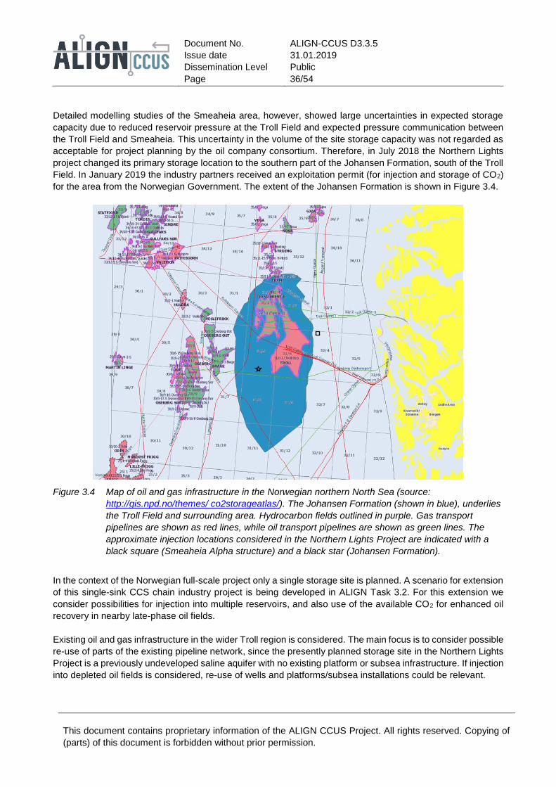
Document No.
Issue date
Dissemination Level
Page
ALIGN-CCUS D3.3.5
31.01.2019
Public
36/54
This document contains proprietary information of the ALIGN CCUS Project. All rights reserved. Copying of
(parts) of this document is forbidden without prior permission.
Detailed modelling studies of the Smeaheia area, however, showed large uncertainties in expected storage
capacity due to reduced reservoir pressure at the Troll Field and expected pressure communication between
the Troll Field and Smeaheia. This uncertainty in the volume of the site storage capacity was not regarded as
acceptable for project planning by the oil company consortium. Therefore, in July 2018 the Northern Lights
project changed its primary storage location to the southern part of the Johansen Formation, south of the Troll
Field. In January 2019 the industry partners received an exploitation permit (for injection and storage of CO2)
for the area from the Norwegian Government. The extent of the Johansen Formation is shown in Figure 3.4.
Figure 3.4 Map of oil and gas infrastructure in the Norwegian northern North Sea (source:
http://gis.npd.no/themes/ co2storageatlas/). The Johansen Formation (shown in blue), underlies
the Troll Field and surrounding area. Hydrocarbon fields outlined in purple. Gas transport
pipelines are shown as red lines, while oil transport pipelines are shown as green lines. The
approximate injection locations considered in the Northern Lights Project are indicated with a
black square (Smeaheia Alpha structure) and a black star (Johansen Formation).
In the context of the Norwegian full-scale project only a single storage site is planned. A scenario for extension
of this single-sink CCS chain industry project is being developed in ALIGN Task 3.2. For this extension we
consider possibilities for injection into multiple reservoirs, and also use of the available CO2 for enhanced oil
recovery in nearby late-phase oil fields.
Existing oil and gas infrastructure in the wider Troll region is considered. The main focus is to consider possible
re-use of parts of the existing pipeline network, since the presently planned storage site in the Northern Lights
Project is a previously undeveloped saline aquifer with no existing platform or subsea infrastructure. If injection
into depleted oil fields is considered, re-use of wells and platforms/subsea installations could be relevant.
Document No.
Issue date
Dissemination Level
Page
ALIGN-CCUS D3.3.5
31.01.2019
Public
37/54
This document contains proprietary information of the ALIGN CCUS Project. All rights reserved. Copying of
(parts) of this document is forbidden without prior permission.
Emerging results from the Norwegian study show that location and timeline will be the major determining
factors when evaluating the possibilities of infrastructure re-use:
Location: Most of the pipelines in this region of the North Sea transport gas in a north-south general direction,
as seen in the map from the GIS-database of the Norwegian Petroleum Directorate in Figure 3.4. These are
therefore not relevant for re-use in a project where CO2 is transport westward from an onshore hub near
Bergen. A smaller number of pipelines cross this region to the coast, either from the Troll Field itself or from a
group of fields further to the north-west. These pipelines pass 10 to 20 kilometres from the Smeaheia and
Johansen storage sites (Figure 3.4) and could be candidates for re-use for CO2 transport. A currently unused
gas condensate pipeline connects the planned ship transport terminal west of Bergen with facilities at
Mongstad further north. Part of this pipeline is suitably located for re-use for transport of CO2 to the Smeaheia
area. If the storage site in the Johansen Formation 50 kilometres south-west of Smeaheia is selected, the
location of the gas condensate pipeline could be less suitable.
Timeline: From available information about oil and gas production activities in the area, it is not likely that the
pipelines from the oil and gas fields in the area will be available for re-use for CO2 transport in the foreseeable
future.
Capacity (pipeline): Information on pipeline transport capacity is available from public data sources. However,
it is not applied and assessed as the infrastructure had been eliminated by application of the timeline of
infrastructure availability criterion.
Table 3.1 Suggested order of application of screening criteria, based on the Norwegian results.
Rank Criteria Data sources
1 Location GIS data at www.npd.no
2 Timeline Estimated from data on remaining reserves and
production history, available on www.npd.no. Public
announcements from NPD on new exploration and
production permits.
3 Capacity Long-distance gas pipeline transport capacity data on
www.gassco.no/en/our-activities/pipelines-and-
platforms.
3.9.2 UK emerging results
The criteria presented in Chapter 3 have been applied to two UK case study sites, the Grangemouth and
Teesside industrial clusters, to assess the potential for re-use of existing oil and gas infrastructure for CO2
transport and storage. These two industrial sites are the focus of technical and non-technical investigations in
the ALIGN project for implementation of industrial CCUS. Prospective storage sites have been selected (Task
3.2) that are suitable for storing the volumes of CO2 anticipated to be captured at each industrial site (Task
5.1). The existing infrastructure in the vicinity of the selected storage sites is appraised in the D3.3.2 report
deliverable. Both of the UK industrial CO2 source clusters selected have been the focus of multiple CCS project
assessments, which helped provide more data to this study than would ordinarily be available. The main
limitation to application of the criteria to a full UK screening is the availability of key data on which to make the
assessment. The order and ease with which the criteria can be applied to the UK, based on the data and
reports available to this study, are discussed below and are summarised in Table 3.2.

Document No.
Issue date
Dissemination Level
Page
ALIGN-CCUS D3.3.5
31.01.2019
Public
38/54
This document contains proprietary information of the ALIGN CCUS Project. All rights reserved. Copying of
(parts) of this document is forbidden without prior permission.
Table 3.2 Suggested order and method of application of screening criteria, based on the UK results.
Rank Criteria Data sources
1 Availability (location) ArcGIS screening (www.ukoilandgasdata.com)
2 Lifespan Internet search
2= Capacity Internet search
4 Materials (well completions) Well reports (available via CDA)
5 Materials (pipelines) Information from Operators
5= Operating pressure Information from Operators
5= Availability (decommissioning timeline) Information from Operators
8 Integrity Detailed study (beyond the scope of a screening
study)
The easiest and quickest, and therefore the first, of the criteria to be considered was the location of
infrastructure based on a review of online GIS data from Oil & Gas UK (www.ukoilandgasdata.com).
Application of this first screening criterion also provided information on what infrastructure is present
(pipelines/platforms/wells), and its current status, in the vicinity of each storage site. Additional relevant
geospatial information is available online from Oil & Gas UK and the Oil and Gas Authority. This includes the
position of the site relative to other competing interests, for example current oil and gas exploration licences,
maritime activity areas and designated environmental sites.
Next, an internet search provided public domain information on when the infrastructure was built, which was
used to estimate a remaining lifespan and whether it could potentially be suitable for a CCS project with an
operational timeframe of more than 20 years. An accurate estimate of the remaining lifespan would require
knowledge of the integrity of the infrastructure and was beyond the scope of this study.
The type of platform and corresponding power-load capacity could also be found via an internet search which
indicated whether the platform could be modified to support CO2 injection wells. Information on the pipeline
diameter, to determine the pipeline capacity, was also quite readily accessible.
The next criterion to be considered was the materials used for any wells drilled at the storage location. This
information is available in well reports, although it is time-consuming to find. Access to well reports requires a
membership or subscription to CDA and associated fees.
Information is required from operators regarding pipeline materials and operating pressure, and availability
with respect to decommissioning timelines. This information was not available to this study beyond what has
been published in previous CCS studies, and so these criteria fall towards the lower end of the order of
application due to difficulty in accessing the information. It would not be practicable to attempt to gather this
information for a UK-wide screening within this research project assessment, although it could be achieved for
prospective storage as part of another targeted study. A UK-wide assessment would require governmental
support and authority.
The last criteria to be considered for a UK site would be the integrity of the infrastructure. Since this requires
a detailed assessment, it would only be completed once a specific site has been selected, and the
infrastructure has met the conditions of the above criteria. It is neither time- nor cost-effective to complete an
integrity assessment at an initial screening level.

Document No.
Issue date
Dissemination Level
Page
ALIGN-CCUS D3.3.5
31.01.2019
Public
39/54
This document contains proprietary information of the ALIGN CCUS Project. All rights reserved. Copying of
(parts) of this document is forbidden without prior permission.
3.9.3 Netherlands emerging results
In the Netherlands a number of studies have been performed into the potential lay-out of an offshore transport
and storage network for CO2, using depleted gas fields as storage reservoirs. Initial studies considered mainly
storage capacity and availability of the fields, according to available production plans, for example, NOGEPA
(2008). Later studies included the status of platforms and wells in an assessment of the feasibility of re-using
a field and its infrastructure (TNO, 2012). Key information includes the number of wells, the number of
abandoned wells and the year of well abandonment. The latter is relevant because of changes in the well
decommissioning regulations.
Pipeline re-use has not been considered in detail yet, although it is expected that in general pipeline re-use
should be feasible provided that the CO2 composition is within specifications (NOGEPA, 2008). In a more
recent study of the potential development of offshore transport and storage networks, the assumption was
used of new pipelines (EBN Gasunie, 2017). For a large number of pipelines, re-use is not possible in the near
term, as these will be in use until the last field is depleted. The re-use of inter-field pipelines has been assessed
from a theoretical point of view; there is little or no data available on the status of individual pipelines. The
feasibility of re-using the pipelines depends on their state after production or after an additional period of
suspension, as mentioned above; the cost of re-use must be compared to the cost of a new, dedicated inter-
field pipeline.
The studies cited above suggest the order of applying criteria for re-use as listed in Table 3.3.
Table 3.3 Order of application of criteria, and method used in the Netherlands studies.
Rank Criteria Data sources
1 Availability and location Data on nlog.nl
2 Capacity (of storage reservoir) Data on nlog.nl (based on gas production history)
3 Integrity (wells) Well data on nlog.nl
4 Lifespan (platform) Well reports on nlog.nl
5 Capacity (pipelines) Data on nlog.nl
3.10 Summary
Technical criteria for the assessment of existing offshore oil and gas infrastructure for re-use in CO2 transport
and storage have been reviewed, building on criteria proposed in WorleyParsons (2013) and IEAGHG (2018).
The applicability of the criteria for the full-chain case studies in the ALIGN-CCUS project is being tested in
ongoing parallel work in the ALIGN project. The emerging findings from each of the case studies on the most
useful order of application of the criteria have been presented. All three countries (Norway, the UK and the
Netherlands) have institutions that maintain publicly available information on many aspects of the ongoing oil
and gas exploration and production. However, ready access to information on infrastructure for each country
is to different levels of detail. The level of detail available free of charge is also different among the countries.
From these publicly available sources, information such as location, construction year, and main parameters
(dimension and purpose) for pipelines can be obtained. This is a great help in the first phase of the screening
process.
Information on the location of existing oil and gas infrastructure is publicly available. This criterion is likely to
place greatest constraint on the number of re-use possibilities; therefore the location aspect of the availability
criterion should be applied first. Availability in time (decommissioning timeline) is also a criterion likely to
markedly reduce the number of re-use possibilities and should be applied early in the screening process if this
information is available. Since the decommissioning timing can be commercially sensitive, detailed information

Document No.
Issue date
Dissemination Level
Page
ALIGN-CCUS D3.3.5
31.01.2019
Public
40/54
This document contains proprietary information of the ALIGN CCUS Project. All rights reserved. Copying of
(parts) of this document is forbidden without prior permission.
is unlikely to be available unless a project is specifically tasked by the owner/operator of a piece of
infrastructure to assess re-use opportunities. However, general policies on oil and gas exploration and
production (e.g. in Norway) would indicate that platforms that serve as hubs for satellite field development, and
the pipelines exporting oil and gas from these, will not be available for re-use for CO2 transport and storage
for the foreseeable future.
The remaining lifespan of infrastructure is not information that is readily available, but the construction year
will give a good indication of whether the infrastructure can be re-used for the duration of a CCS project. This
is therefore recommended as a criterion to be applied early on. Likewise, openly available basic information
on the infrastructure, such as type and purpose, will give some indication on both weight capacity for platforms
and transport capacity for pipelines. However, the capacity indicated by the original design parameters may
have been reduced due to wear during hydrocarbon operations, and a detailed assessment will be necessary
to reduce the uncertainty in capacity when used for CO2 transport and storage. This detailed assessment will
only be possible using data supplied by the operator and/or until inspection of the infrastructure has been
conducted, such as a corrosion inspection on the exterior and interior of pipelines. A detailed capacity
assessment is therefore one of the last criteria that should be assessed, following an integrity assessment.
The material compatibility can probably be inferred from the previous use of the installation, and so the
design standards it would meet. However, detailed assessment of this criterion will need data only available to
the owner or operator.
Assessment of the integrity of the infrastructure will not be possible until a detailed inspection has been
conducted. This probably means that this criterion can only be evaluated with data from the owner/operator.
Reports from previous inspections will give an indication on the rate of corrosion during the present use of the
infrastructure. The maximum allowed working pressure of a pipeline in re-use for CO2 transport can only be
properly evaluated after the integrity assessment.
Testing of the application of the re-use criteria proposed by WorleyParsons (2013) and IEAGHG (2018) to the
three national case studies in ALIGN Task 3.3 has identified an addition to the criteria for infrastructure re-use.
Site CO2 storage capacity was considered when applying the proposed criteria in all three national case
studies in ALIGN Task 3.3. The practise of application of the criteria for infrastructure re-use in the Netherlands
highlights this key property of the storage site to which the infrastructure is connected which determines
whether it would be considered for re-use. The CO2 storage capacity is a highly ranked criterion for
infrastructure for re-use in the Netherlands (Table 3.3). The capacity of depleted hydrocarbon field stores is
known and the provision of storage must be matched to the forecast and timing of CO2 supply. In the Norwegian
case study infrastructure in proximity to the first-investigated Smeaheia Alpha structure, for which the storage
capacity is not sufficiently certain, is distinct from infrastructure in the vicinity of the selected Johansen
Formation (Figure 3.4). Similarly, CO2 storage capacity was a significant factor for selection of UK sites that
are sufficient to receive the forecast supply from industrial source clusters.
Location of the infrastructure remains the first-applied and strongest criterion when screening for re-use,
However, the results from ALIGN Task 3.3 include proximity to sites of sufficient CO2 storage capacity when
applying the criterion of location of infrastructure when screening for re-use.
These considerations lead to the following table with suggestions for the order of application of the re-use
criteria.

Document No.
Issue date
Dissemination Level
Page
ALIGN-CCUS D3.3.5
31.01.2019
Public
41/54
This document contains proprietary information of the ALIGN CCUS Project. All rights reserved. Copying of
(parts) of this document is forbidden without prior permission.
Table 3.4 Suggested order of application of the technical criteria, and the information that can be found for
each criterion from public or confidential data sources. Note that 'public' does not imply 'free of
charge'.
Rank Criteria Public data sources Detailed information from
operator
1 Location of
infrastructure relative to
sites of sufficient CO2
storage capacity.
GIS screening – all country regulators
(Norway/UK/Netherlands) show the
location of pipelines/wells/fields in a map
view.
Possible conflicts with other
installations.
2 Timeline of availability
for re-use. Access to
infrastructure.
Inference from reserves estimates and
production history of the field. Also from the
state of surrounding oil and gas activities.
Estimate from detailed knowledge
on production history, further
development plans and remaining
reserves.
3 Remaining lifespan of
infrastructure
Inference from construction date and the
previous use.
Estimate from design parameters
and reports from previous
inspections.
4 Transport capacity /
Weight capacity
Inference from the diameter and previous
use (pipelines).
Analogy with earlier studies on similar
constructions (platforms).
Estimate based on design
parameters (such as operating
pressure), reports from previous
inspections.
5 Compatibility of
materials
Can be inferred from previous use. Confer with detailed inventory lists.
6 Integrity of wells (for
depleted hydrocarbon
fields).
Insufficient publicly available information to
complete an assessment
Available inspection reports, if
routine inspections have been
performed.
7 Materials (well
completions)
Limited information available. Well
construction reports could be available for
exploration wells, but these are usually
plugged and abandoned. Details of
production wells are not published.
Consult list of materials used for
casings, cement, packers etc.
If the storage site is an abandoned oil or gas field the availability criteria may already be met, in particular if
the case being investigated is led by the operator of the field looking for sources of CO2 to store. However, as
discussed in section 3.1, it should be kept in mind that there are also a number of non-technical issues to be
considered regarding re-use of the storage site, including sufficient capacity to justify its re-use for CO2 storage.

Document No.
Issue date
Dissemination Level
Page
ALIGN-CCUS D3.3.5
31.01.2019
Public
42/54
This document contains proprietary information of the ALIGN CCUS Project. All rights reserved. Copying of
(parts) of this document is forbidden without prior permission.
4 Summary and conclusions
Achievement of CO2 emissions reductions by the industry and power sectors will require large-scale
deployment of CO2 capture, transport, utilisation and storage (CCUS) (IPCC, 2018). The CO2 storage capacity
in the North Sea has been investigated both at a regional scale and for selected individual storage sites and
is predicted to be more than sufficient to meet the demand from the North Sea countries.
The North Sea is a mature petroleum province and hosts an extensive network of infrastructure that will
become increasingly available for re-use for CO2 transport and storage as oil and gas production declines.
Once available, existing oil and gas infrastructure may be transferred or adapted to support the deployment of
CO2 transport and storage networks. Re-use of infrastructure can help to reduce the cost of CO2 capture,
transport and storage projects, which is critical to ensuring widespread commercialisation of these
technologies to meet European and national targets for decarbonisation.
Several previous studies of proposed CO2 transport and storage networks have established that re-use of
some of the existing oil and gas infrastructure is technically feasible and can be cost effective. For example,
pipelines for oil and gas transport are in most cases constructed of materials that are compatible with a CO2
stream, and platforms can be modified to serve as transport hubs and to contain facilities for injection of CO2
into the subsurface storage reservoirs. There are, however, both technical and legal challenges with re-use of
existing infrastructure, and neither its suitability, nor availability can be presumed. The technical criteria that
need to be met have been discussed in previous studies of re-use possibilities. This report has reviewed the
criteria proposed in the previous studies and proposes an order of application of the criteria in order to arrive
at a methodology for evaluation of re-use possibilities for the CCUS chains in the ALIGN-CCUS project. The
legal challenges with possible re-use of oil and gas infrastructure for CO2 transport and storage is given in a
separate report from the project (deliverable D3.3.4).
The first chapter of this report gives a general overview of the infrastructure components needed for the
transport and storage of CO2. Most of these components are well known from the oil and gas industry. The
second chapter gives an overview of sources of information on existing infrastructure components in use in
the offshore oil and gas industry in the UK, Norway and the Netherlands. In all three countries there exist
publicly accessible databases on oil and gas infrastructure, with information on location, installation year and
high-level details on its function. In Norway and the Netherlands access to these databases is open and free
of charge, while the corresponding database in the UK requires a membership agreement or a subscription.
Chapter three is the main chapter of this report and describes the technical criteria that can be used to assess
the re-usability of infrastructure components, and proposes an order of application of these criteria. The criteria
covered are:
• Location;
• timeline of decommissioning;
• remaining lifespan;
• integrity;
• operating pressure;
• capacity; and
• material compatibility.
While the criteria have been defined and discussed in previous studies, the discussion has often been in the
context of specific late-phase oil and gas fields and the possibility of using the reservoir as a CO2 storage site.
For these study cases the location and the selection of infrastructure components are given, and the question
of re-use in the end is often about whether a suitable CO2 capture project can be found within reasonable
distance from the depleted field. For the ALIGN-CCUS project the CO2 sources are given, and the re-use issue

Document No.
Issue date
Dissemination Level
Page
ALIGN-CCUS D3.3.5
31.01.2019
Public
43/54
This document contains proprietary information of the ALIGN CCUS Project. All rights reserved. Copying of
(parts) of this document is forbidden without prior permission.
is concerned with whether there is existing oil and gas infrastructure that can be re-used in a chain connecting
the CO2 sources with sites of sufficient storage capacity. Since, in the North Sea, prospective CO2 storage
sites are known wherever there is petroleum activity today, the methodology in the present report is applicable
also in a wider screening of re-use opportunities for the entire offshore North Sea region.
The analysis of previous case studies and emerging results from the case studies in the ALIGN-CCUS project
lead us to propose the following order of application of the technical criteria for re-use assessment. The criteria
believed to have the strongest influence on the re-use possibilities should be evaluated first. These are the
location of the infrastructure, the timeline of availability and the remaining lifespan. Experience of applying the
criteria in Norway, the UK and the Netherlands in ALIGN is that the location of infrastructure relative to sites of
known and sufficient CO2 storage capacity is essential when screening for re-use. The location of infrastructure
will be known from publicly available data. The availability and lifespan can only be accurately estimated with
data from operators, although first estimates can be made with publicly available information. For infrastructure
where all of the three first criteria are met, the remaining criteria can be evaluated. Most can only be
approximately assessed with publicly available data sources. However, since the number of remaining
candidates for a given project should be much smaller at this stage, the task of obtaining more detailed
information from operators should be manageable.
Table 4.1 Suggested order of application of technical criteria for re-use assessment for existing oil and
gas infrastructure in CO2 transport and storage.
Rank Criteria Public data sources Detailed information from operator
1 Location of
infrastructure relative to
sites of sufficient CO2
storage capacity.
GIS screening – all country regulators
(NPD in Norway, OGA in the UK and
NLOG in the Netherlands) show the
location of pipelines/wells/fields in a map
view.
Possible conflicts with other
installations.
2 Timeline of availability
for re-use. Access to
infrastructure.
Inference from reserves estimates and
production history of the field. Also from
the state of surrounding oil and gas
activities.
Estimate from detailed knowledge on
production history, further
development plans and remaining
reserves.
3 Remaining lifespan of
infrastructure.
Inference from construction date and the
previous use.
Estimate from design parameters and
reports from previous inspections.
4 Transport capacity /
Weight capacity
Inference from the diameter and previous
use (pipelines).
Analogy with earlier studies on similar
constructions (platforms)
Estimate based on design parameters
(such as operating pressure), reports
from previous inspections.
5 Compatibility of
materials.
Inference from previous use. Confer with detailed inventory lists.
6 Integrity of wells (for
depleted hydrocarbon
fields).
Insufficient publicly available information
to complete an assessment
Available inspection reports, if routine
inspections have been performed
7 Materials (well
completions)
Limited information available. Well
construction reports could be available
for exploration wells, but these are
usually plugged and abandoned. Details
on production wells are not published.
Consult list of materials used for
casings, cement, packers etc.

Document No.
Issue date
Dissemination Level
Page
ALIGN-CCUS D3.3.5
31.01.2019
Public
44/54
This document contains proprietary information of the ALIGN CCUS Project. All rights reserved. Copying of
(parts) of this document is forbidden without prior permission.
List of abbreviations and acronyms
ACT Accelerating CCS Technologies
BAT Best Available Techniques
BOP Blow-Out Preventer
CCS Carbon Dioxide Capture and Storage
CCUS Carbon Dioxide Capture, Utilisation and Storage
CDA Common Data Access Limited – the UK entity established by Oil and Gas UK to provide a
centralized data storage and management system for UK seismic and well data
CO2 Carbon dioxide
DCS Dutch Continental Shelf
DEAL Digital Energy Atlas and Library, index of UK hydrocarbon production licence data – now
incorporated into the CDA database
DECC/DTI see OGA
EOR/EGR Enhanced Oil Recovery/Enhanced Gas Recovery
ETS (European) Emission Trading Scheme
FEED Front-end Engineering and Design study
FPSO Floating Production, Storage, and Offloading facility
FSO Floating Storage and Offloading facility
GIS Geographical Information System: software for display of spatial data
IEAGHG International Energy Agency Greenhouse Gas R&D programme
IMO International Maritime Organization
ISO International Organization for Standardization
LNG Liquefied Natural Gas
LPG Liquefied Petroleum Gas
MAOP Minimum Allowable Operational Pressure
NCS Norwegian Continental Shelf
NPD Norwegian Petroleum Directorate
OGA Oil and Gas Authority – the UK Government organization responsible for regulating oil and gas
activity on the UK Continental Shelf. Formerly the Department of Energy and Climate Change
(DECC), and Department of Trade and Industry (DTI).
Oil & Gas UK The UK Industry and Trade Association that represents the UK offshore oil and gas sector,
including operators, non-operators, and contractors. Formerly the UK Offshore Operators
Association (UKOOA).
OSPAR Oil Spill Prevention, Administration, and Response
RKB Rotary Kelly Bushing
SPM Single point mooring facility
TUF Transport and utilisation facilities
UKCS United Kingdom Continental Shelf
UNCLOS United Nations Convention on the Law of the Sea

Document No.
Issue date
Dissemination Level
Page
ALIGN-CCUS D3.3.5
31.01.2019
Public
45/54
This document contains proprietary information of the ALIGN CCUS Project. All rights reserved. Copying of
(parts) of this document is forbidden without prior permission.
5 References
ASPELUND, A., MØLNVIK, M. J. AND DE KOEIJER, G. (2006). Ship transport of CO2. Technical solutions and analysis of costs, energy utilization, exergy efficiency and CO2 emissions. Chemical Engineering Research and Design 84(A9): 847-855.
BENTHAM, M., MALLOWS, T., LOWNDES, J. AND GREEN, A. (2014). CO2 STORage Evaluation Database (CO2 Stored). The UK's online storage atlas. Energy Procedia 63: 5103-5113. https://doi.org/10.1016/j-egypro.2014.11.540.
DE VISSER, E., HENDRIKS, C., BARRIO, M., MØLNVIK, M., DE KOEIJER, G., LILJEMARK, S. AND GALLO, Y. L. (2008). Dynamis CO2 quality recommendations. International Journal of Greenhouse Gas Control 2: 478-484. https://doi.org/10.1016/j.ijggc.2008.04.006.
DEPARTMENT OF ENERGY & CLIMATE CHANGE (2016). Carbon Capture and Storage Knowledge Sharing: Technical Subsurface and Well Engineering. Knowlegde gathered from the Peterhead and White Rose Carbon Capture & Storage projects. https://www.gov.uk/government/publications/carbon-capture-and-storage-knowledge-sharing-technical-subsurface-and-well-engineering
DNV-GL (2017). Recommended Practice, Design and operation of carbon dioxide pipelines. DNV-GL-RP-F104. https://rules.dnvgl.com/docs/pdf/DNVGL/RP/2017-11/DNVGL-RP-F104.pdf
EBN GASUNIE (2017). Transport en opslag van CO2 in Nederland (in Dutch). https://www.ebn.nl/wp-content/uploads/2018/07/Studie-Transport-en-opslag-van-CO2-in-Nederland-EBN-en-Gasunie.pdf
ELEMENT ENERGY (2010). One North Sea. A study into North Sea cross-border CO2 transport and storage. Report on behalf of The North Sea Basin Task Force. http://www.element-energy.co.uk/wordpress/wp-content/uploads/2010/08/OneNorthSea.pdf
EQUINOR (2018). Forslag til utredningsprogram for konsekvensutredning (Proposed impact assessment programme). Available at https://www.equinor.com/content/dam/statoil/documents/impact-assessment/northern-lights/statoil-northern-lights-forslag-til-utredningsprogram-for-ku.pdf
EUROPEAN COMMISSION (2011). Guidance Document 1: CO2 Storage Life Cycle Risk Management Framework; Guidance Document 2: Characterisation of the Storage Complex, CO2 Stream Composition, Monitoring and Corrective Measures; Guidance Document 3: Criteria for Transfer of Responsibility to the Competent Authority; Guidance Document 4: Article 19 Financial Security and Article 20 Financial Mechanism. The Guidance Documents are available on the website of the European Commission: https://ec.europa.eu/clima/policies/lowcarbon/ccs/implementation_en#tab-0-1.
EUROPEAN COMMISSION (2012). COMMISSION OPINION of 28.2.2012 relating to the draft permit for the permanent storage of carbon dioxide in block section P18-4 of block section P18a of the Dutch continental shelf, in accordance with Article 10(1) of Directive 2009/31/EC of 23 April 2009 on the geological storage of carbon dioxide. C(2012) 1236 final.
EUROPEAN COMMISSION (2015). Climate action progress report, including the report on the functioning of the European carbon market and the report on the review of Directive 2009/31/EC on the geological storage of carbon dioxide, COM(2015) 576 final.
EUROPEAN COMMISSION (2016). COMMISSION OPINION of 20.1.2016 on a draft permit for the permanent storage of carbon dioxide in the depleted Goldeneye gas condensate field located in blocks 14/28b, 14/29a, 14/29e, 20/3b, 20/4b and 20/4c on the United Kingdom Continental Shelf, in accordance with Article 10(1) of Directive 2009/31/EC of 23 April 2009 on the geological storage of carbon dioxide. C(2016) 152 final.
HANSEN, O., GILDING, D., NAZARIAN, B., OSDAL, B., RINGROSE, P., KRISTOFFERSEN, J.-B., EIKEN, O. AND HANSEN, H. (2013). Snøhvit: The History of Injecting and Storing 1 Mt CO2 in the Fluvial Tubåen Fm. Energy Procedia 37: 3565-3573. https://doi.org/10.1016/j.egypro.2013.06.249.
IEAGHG (2017). Case studies of CO2 storage in depleted oil and gas fields. IEAGHG Technical Report 2017-01, IEA Greenhouse Gas R&D programme
IEAGHG (2018). Re-use of oil and gas facilities for CO2 transport and storage. IEAGHG Technical Report 2018-06, IEA Greenhouse Gas R&D programme
IPCC (2018). Summary for Policymakers. In: Global warming of 1.5°C. An IPCC Special Report on the impacts of global warming of 1.5°C above pre-industrial levels and related global greenhouse gas emission pathways, in the context of strengthening the global response to the threat of climate change, sustainable

Document No.
Issue date
Dissemination Level
Page
ALIGN-CCUS D3.3.5
31.01.2019
Public
46/54
This document contains proprietary information of the ALIGN CCUS Project. All rights reserved. Copying of
(parts) of this document is forbidden without prior permission.
development, and efforts to eradicate poverty, World Meteorological Organization, Geneva, Switzerland. Available at https://www.ipcc.ch/site/assets/uploads/sites/2/2018/07/SR15_SPM_High_Res.pdf
ISO-TRYYKÄRI, M., RAURAMO, J. AND PEKKANEN, E. (2011). FINNCAP - Meri-Pori CCS demonstration project. Energy Procedia 4: 5599-5606. https://doi.org/10.1016/j.egypro.2011.02.549.
JANSEN, F., STEINZ, R. AND VAN GELDER, B. (2011). Potential for CO2 storage in depleted fields on the Dutch Continental Shelf - Cost estimate for offshore facilities. Energy Procedia 4: 3079-3086. https://doi.org/10.1016/j.egypro.2011.02.220.
NOGEPA (2008). Potential for CO2 storage in depleted gas fields at the Dutch continental shelf - Phase 1: technical assessment. https://www.nlog.nl/sites/default/files/f353faea-f50f-4102-9803-fe16ce7062a0_dhv%20tno%20ccs%20offshore%20final%2030-06-08.pdf
NOOTHOUT, P., WIERSMA, F., HURTADO, O., MACDONALD, D., KEMPER, J. AND VAN ALPHEN, K. (2014). CO2 Pipeline infrastructure - lessons learnt. Energy Procedia 63: 2481-2492. http://www.doi.org/10.1016/j.egypro.2014.11.271.
NORWEGIAN PETROLEUM DIRECTORATE (2014). Compiled CO2 atlas for the Norwegian Continental Shelf. http://www.npd.no/en/Publications/Reports/Compiled-CO2-Atlas/.
OGA (2017). Oil and Gas Authority Wellbore Standard. Available at https://data.gov.uk/dataset/b1edb405-5d5d-4fc7-932f-0bc6b1c32091/oga-basic-wellbore-standard
OIL & GAS UK (2017). Code of Practice on Access to Upstream Oil and Gas Infrastructure on the UK Continental Shelf. Available at https://oilandgasuk.co.uk/infrastructure-code-of-practice-2/
PALE BLUE DOT ENERGY LTD. (2016). Progressing Development of the UK's Strategic Carbon Dioxide Storage Resource. A summary of results from the Stategic UK CO2 Storage Appraisal Project, Pale Blue Dot Energy. Available at https://pale-blu.com/category/strategic-uk-co2-storage-appraisal-project/
SHELL (2016). FEED Summary Report for Full CCS Chain. Peterhead CCS Project, K03-11.133. https://assets.publishing.service.gov.uk/government/uploads/system/uploads/attachment_data/file/531394/11.133_-_FEED_Summary_Report_for_Full_CCS_Chain.pdf
TNO (2012). Independent assessment of high-capacity offshore storage options. TNO report TNO-060-UT-2012-00414/B. http://decarboni.se/sites/default/files/publications/35621/independent-assessment-high-capacity-offshore-co2-storage-options-opt.pdf
VERMEULEN, T. (2011). Overall supply chain optimization - CO2 liquid logistics shipping concept, Tebodin Consultants & Engineers. http://decarboni.se/sites/default/files/publications/19011/co2-liquid-logistics-shipping-concept-llsc-overall-supply-chain-optimization.pdf
VERMEULEN, T. N. (2009). Potential for CO2 storage in depleted fields on the Dutch Continental Shelf - Cost estimate for offshore facilities, Tebodin/EBN
WETENHALL, B., AGHAJANI, H., CHALMERS, H., BENSON, S., FERRARI, M., LI, J., RACE, J., SINGH, P. AND DAVISON, J. E. (2014). Impact of CO2 impurity on CO2 compression, liquefaction and transportation. Energy Procedia 63: 2764-2776.
WILDGUST, N., GILBOY, C. AND TONTIWACHWUTHIKUL, P. (2013). Introduction to a decade of research by the IEAGHG Weyburn–Midale CO2 Monitoring and Storage Project. International Journal of Greenhouse Gas Control 16: S1-S4. https://doi.org/10.1016/j.ijggc.2013.03.014.
WORLEYPARSONS (2013). Key criteria for assessing suitability of infrastructure for CO2 transportation. Confidential report prepared for The Crown Estate.
ZEP (2011). The cost of CO2 transport, Zero emissions platform. http://www.zeroemissionsplatform.eu/library/publication/167-zep-cost-report-transport.html
ZEP (2017). Future CCS Technologies, Zero emissions platform. http://www.zeroemissionsplatform.eu/library/publication/270-futureccstechnologies.html
ØIA, T. M., AARLOTT, M. M. AND VRÅLSTAD, T. (2018). Innovative approaches for full subsea P&A create new opportunities and cost benefits. SPE-191315-MS. SPE Norway One Day Seminar, Bergen, Norway.

Document No.
Issue date
Dissemination Level
Page
ALIGN-CCUS D3.3.5
31.01.2019
Public
47/54
This document contains proprietary information of the ALIGN CCUS Project. All rights reserved. Copying of
(parts) of this document is forbidden without prior permission.
Appendix A Transport and storage infrastructure components A description of infrastructure components currently in use for oil and gas production and transport is given in
Appendix A. It provides more detail on the infrastructure components than in the report text.
Appendix A.1 Pipelines
A production system for oil and gas can contain several types of piping and pipelines, including the flowline
transporting all produced fluids from the production well to the production facility, the gathering or sales
pipelines connecting various pieces of production and treatment equipment, and the transmission pipeline that
transports the processed petroleum product long distances.
Fig. A.1 Illustration of pipes and pipelines connecting the wellhead to the market. From PetroWiki
(http://petrowiki.org/Piping_and_pipeline_systems).
Several thousands of kilometres of transmission pipelines are in use today for the transport of oil and (natural)
gas from the North Sea to markets in the UK and mainland Europe. Offshore gas pipelines are also in use in
the Baltic Sea for transport of natural gas from Russia to the German north-east coast. Gas Infrastructure
Europe (www.gie.eu) collects information of current gas transport infrastructure and maintains various maps.
Pipes
The pipeline itself is typically constructed in steel, covered externally with corrosion protection and internally
with an antifriction coating. Offshore pipelines are commonly weighted down with a cement jacket to counteract
buoyancy, as illustrated in Fig. A.2. Pipelines in use today typically have diameters from 6 to 48 inches
(approximately 15 cm to 1.2 m). Due to wall effects, the transport capacity of a pipeline with fixed inlet and
outlet pressures will increase more than the increase in cross section when the diameter is increased. Since
the amount of steel needed scales approximately with the diameter, a single large diameter pipeline will be
preferred over several smaller pipelines provided the increased capacity can be utilised.

Document No.
Issue date
Dissemination Level
Page
ALIGN-CCUS D3.3.5
31.01.2019
Public
48/54
This document contains proprietary information of the ALIGN CCUS Project. All rights reserved. Copying of
(parts) of this document is forbidden without prior permission.
Fig. A.2 Illustration of typical pipe cross section. From the Nord Stream 2 web page (https://www.nord-
stream2.com/project/construction).
Maintenance sections
These include facilities for pipeline inspection and cleaning. To ensure efficient and safe operation of the
pipelines, operators routinely inspect their pipelines for corrosion and defects. This is done using maintenance
tools commonly called pigs. Pigs are intelligent robotic devices that are propelled down pipeline to evaluate
the interior of the pipe. Pigs can test pipe thickness and roundness, check for signs of corrosion, detect minute
leaks, and any other defect along the interior of the pipeline that may either impede the flow of gas or pose a
potential risk for the operation of the pipeline. The export facility must contain equipment to safely insert and
retrieve pigs from the pipeline as well as depressurization, referred to a pig launchers and pig receivers.
Appendix A.2 Shipping
Shipping of CO2 has been established since before 2005 (Aspelund et al., 2006), but experience to date is
only limited to smaller carriers. Both Yara (vessels managed & operated by Larvik Shipping AS) and Anthony
Veder have been operating small dedicated food-grade CO2 carriers having a capacity of 900 to 1250 tonnes,
for about a decade. Pressurised CO2 at 18 bar (gauge) is transported at a temperature of −40°C (ZEP, 2017).
The port to port shipping option could consist of four different elements:
1) onshore terminal at an onshore collection hub for intermediate storage of the liquefied CO2,
2) loading to the vessel(s),
3) offloading terminal and intermediate storage facility, and
4) onshore pipeline which will connect the offloading port facility with the pipeline network.
The implementation of a ship transport chain depends on the location of the loading and unloading sites. In an
analysis of the cost of CO2 transport ZEP considers a number of ship transport options (ZEP, 2011). Vermeulen
(2011) describes in detail the technical set-up of a ship transport link to an offshore offloading site.
It is generally believed that ships designed for transport of pressurised liquids, such as ammonia, liquefied light
hydrocarbons, ethylene and LNG can be adapted for transport of CO2 at a relatively low cost. Barges are not
currently in use for transport of CO2. Current regulations permit only sea-going vessels for CO2 transport.

Document No.
Issue date
Dissemination Level
Page
ALIGN-CCUS D3.3.5
31.01.2019
Public
49/54
This document contains proprietary information of the ALIGN CCUS Project. All rights reserved. Copying of
(parts) of this document is forbidden without prior permission.
Appendix A.3 Platforms
Platforms can be broadly categorised into fixed and moveable platforms. Fixed platforms have a leg(s)
extending to the sea floor that carry the weight of the platform. Fixed platforms are used to drill production
wells and to produce oil and/or gas. Their main purpose during production is to receive the oil and/or gas
produced, to separate the oil and gas, remove water, and in general perform the necessary treatment for
transport to land.
Exploration wells are always drilled from movable platforms. Movable platforms may also be used to drill
production wells for fixed platforms, to drill and produce oil and/or gas from small fields and to drill satellite
wells with wellhead at the sea bottom.
Fig. A.3 Various platform types in use offshore. (Source: Oil and Gas Journal; https://www.ogj.com/
articles/print/volume-96/issue-44/in-this-issue/general-interest/new-designs-advance-spar-
technology-into-deeper-water.html.)
Movable platforms (or drill ships) contain the same basic elements as the fixed platforms, except that the
wellhead and the BOP (blow-out preventer) are mounted on the sea bottom, below the platform. In this case
the BOP is connected to the platform above it by a riser. The connection between the riser and BOP is flexible,
allowing the platform to move somewhat without damaging the riser.
Fixed platforms may also be employed for intermediate storage of produced oil and as transport hubs for oil
and gas.
The main components of the production system on a platform are:
Production manifold
Connecting the production wells to the various separators (high/low-pressure separators).

Document No.
Issue date
Dissemination Level
Page
ALIGN-CCUS D3.3.5
31.01.2019
Public
50/54
This document contains proprietary information of the ALIGN CCUS Project. All rights reserved. Copying of
(parts) of this document is forbidden without prior permission.
Separation
Some wells produce only gas which can be taken directly to gas treatment and/or compression. More often, a
well gives a combination of gas, oil and water and various contaminants which must be separated and
processed.
Gas compression
Gas from a pure natural gas wellhead in the early phases of field life might have sufficient pressure to feed
directly into a pipeline transport system. Gas form the late stages of field life and gas from separators has
generally lost so much pressure that it must be recompressed to be transported. The compression includes a
large section of associated equipment such as scrubbers (removing liquid droplets) and heat exchangers, lube
oil treatment etc.
Utility systems
Remote installations such as off-shore platforms are often fully self-sustainable and thus must generate their
own power, water etc.
Appendix A.4 Subsea installations
Smaller fields not too far from existing fixed platforms with available processing capacity are frequently
developed as satellite fields where the untreated well stream is transported to the platform. Examples can also
be found of larger installations such as gas booster stations being built as subsea installations due to weight
or space limitations on the production platform for the field.
Appendix A.5 Wells
Wells drilled in the offshore oil and gas industry varies considerably in detail from well to well according to
specific needs and the intended function. Common construction principles can be identified in Fig. A.4, such
as the use of multiple casings, cementing of the casing shoe in place, a packer around the production tubing
isolating the innermost casing from the open hole at the bottom. At the wellhead there need to be a stack of
valves commonly called the Christmas tree, which includes safety installations such as blow-out preventers
(BOP).

Document No.
Issue date
Dissemination Level
Page
ALIGN-CCUS D3.3.5
31.01.2019
Public
51/54
This document contains proprietary information of the ALIGN CCUS Project. All rights reserved. Copying of
(parts) of this document is forbidden without prior permission.
Fig. A.4 Illustration of typical oil and gas production well. The two versions differ in the orientation of the
Christmas tree; horizontal on the left and vertical on the right. From Øia et al. (2018).
Production wells are divided into production and injection wells. In addition, exploration wells are used for
testing the existence of hydrocarbon reserves in a prospect. Exploration wells can later be converted to
production wells, particularly for smaller developments where several wells would be too costly. Production
wells are, as the name indicates, for production of oil and gas, and can be drilled as (mainly) vertical wells or
as deviated and even horizontal wells (i.e. mainly horizontal in the section of the well that is at reservoir depth).
Injection wells are drilled to inject gas or water into the reservoir, and can also be drilled for disposal of
produced water into a separate formation. The purpose of injection into the producing reservoir is to maintain
reservoir pressure and drive the oil toward the production wells. The design of injection wellheads is
fundamentally the same as for production wellheads. The difference is the direction of flow and, therefore,
mounting of some directional components, such as the choke.
Once the well has been drilled, it must be completed. Completing a well consists of a number of steps, such
as installing the well casing, completion, installing the wellhead, and installing lifting equipment or treating the
formation, if required.
Well casings
The well casing consists of a series of concentric metal tubes installed in the freshly drilled hole. The casing
serves to strengthen the sides of the well hole, isolate the reservoir fluids form the shallower formations, and
isolate shallower formations from each other. To achieve this zonal isolation it is necessary to fill the annular

Document No.
Issue date
Dissemination Level
Page
ALIGN-CCUS D3.3.5
31.01.2019
Public
52/54
This document contains proprietary information of the ALIGN CCUS Project. All rights reserved. Copying of
(parts) of this document is forbidden without prior permission.
space between the outermost casing and the sides of the drilled hole with a material that blocks fluid flow in
suitable intervals. Typically, well cement is used for this, and this also locks the casing in place.
The types of casing used depends on the subsurface characteristics of the well, including the diameter of the
well (which is dependent on the size of the drill bit used) and the pressures and temperatures experienced. In
most wells, the diameter of the well-hole decreases the deeper it is drilled, leading to a conical shape that must
be taken into account when installing casing. The lowermost casing, the production casing, runs down to the
level of the producing reservoir. Inside this, the production tubing is installed, with a packer to close the annular
space between the tubing and the production casing.
Well completion
The production casing can run all the way through the producing (or injecting) section of the well to avoid
collapse of the well. Perforations are then needed for transmission of fluids. Screens or filters can be installed
to prevent influx of sand from weak formations. The process of finishing a well so that it is ready to produce oil
or natural gas in this way is referred to as Well completion.
Well head
The well head connects the casings and production tubing with the riser to the platform. The wellhead consists
of three components: the casing head, the tubing head, and the “Christmas tree”. The well head can be
installed subsea (at the sea bottom) or on the topside on an offshore installation.

Document No.
Issue date
Dissemination Level
Page
ALIGN-CCUS D3.3.5
31.01.2019
Public
53/54
This document contains proprietary information of the ALIGN CCUS Project. All rights reserved. Copying of
(parts) of this document is forbidden without prior permission.
Appendix B ISO standards for use in the oil and gas industry

Document No.
Issue date
Dissemination Level
Page
ALIGN-CCUS D3.3.5
31.01.2019
Public
54/54
This document contains proprietary information of the ALIGN CCUS Project. All rights reserved. Copying of
(parts) of this document is forbidden without prior permission.
Appendix C NORSOK standards for use in the oil and gas industry